7月制造业采购经理指数下降为50.0%
- 格式:doc
- 大小:2.44 KB
- 文档页数:1

Applicable to Shapes: Shape DimensionsNomenclature & Permissible VariationsHP,M&WUnitsSymbolCommonNameEnglishMetric Permissible VariationsA Cross-sectional Area in2 mm2Õ Calculated from SDI shape – information onlyb f Flange Width in mm As per latest edition of ASTM A6/A6Md Flange Depth in mm As per latest edition of ASTM A6/A6Mk ‘k’ – line in mm Detailing dimension – information onlyk1“k1” – line in mm Detailing dimension – information onlyL Length ft,inmÕLength cutting tolerance as per current SDI price page R Fillet Radius in mm Mill practice – information onlyT ‘Clear” Web in mm Detailing dimension – information onlyt f Flange Thickness in mm As per latest edition of ASTM A6/A6Mt w Web Thickness in mm As per latest edition of ASTM A6/A6Mw Weight / Mass lbs/ft kg/m As per latest edition of ASTM A6/A6MÕDenotes deviation from ASTM A6/A6MThe permissible dimensional variations of structural long products manufactured by Steel Dynamics Inc,Structural and Rail Division, conform to the latest edition of ASTM A6/A6M. Cross-sectional areas in thefollowing tables are calculated from nominal dimensions, and include the nominal fillet radius employed by Steel Dynamics Inc. Consequently, the tabulated values may slightly deviate from those published in ASTM A6/A6M.Nominal detailing dimensions are provided as a courtesy. Permissible dimensional variations, and rollingfactors (such as roll wear), may result in supplied shapes differing from the tabulated values. Consequently, allowances should be made for proper fitting and connections.Piece length tolerance deviates from ASTM A6/A6M. Please consult the current price page for mill practice.*Please note that Steel Dynamics, Inc. reserves the right to produce material in either the Heavy Section Mill (HSM) or the Medium Section Mill (MSM).Wide FlangeBeamsInch-Pound SectionsInch - Pound SizesComparable Metric Sizes Inch - Pound SizesComparable Metric Sizes Prime SectionGroupWeight range in GroupPrime Section Group Weight range inGroupPrime SectionGroupWeight range in GroupPrime Section Group Weight range inGroup (in x in) (lbs/ft) (mm x mm)(kg/m)(in x in) (lbs/ft)(mm x mm)(kg/m)4 x 413 100 x 10019.3 14 x 6.75 30 - 38 360 x 170 44.6 - 5814 x 5 22 - 26360 x 13032.9 - 395 x 5 16 - 19 130 x 13023.8 - 28.116 x 10.2567 - 100 410 x 260 100 - 149 6 x 6 15 - 25 150 x 150 22.5 - 37.1 16 x 7 36 - 57 410 x 180 53 - 85 6 x 4 8.5 - 16 150 x 10013 - 2416 x 5.5 26 - 31410 x 14038.8 - 46.18 x 8 31 - 67 200 x 200 46.1 - 100 18 x 11 76 - 211 460 x 280 113 - 315 8 x 6.5 24 - 28 200 x 170 35.9 - 41.7 18 x 7.5 41 - 71 460 x 190 60 - 106 8 x 5.25 14 - 21 200 x 130 21.0 - 31.3 18 x 6 35 - 46460 x 15052 - 688 x 4 10 - 15 200 x 10015.0 - 22.521 x 12.25101 - 201 530 x 310 150 - 300 10 x 10 49 - 112 250 x 250 73.0 - 167 21 x 8.25 48 - 93 530 x 210 72 - 138 10 x 8 33 - 45 250 x 200 49.1 - 67.0 21 x 6.5 44 - 57530 x 17066 - 8510 x 5.75 16 - 30 250 x 150 24.0 - 44.810 x 4 12 - 19 250 x 10017.9 - 28.424 x 12.75104 - 192 610 x 320 155 - 28524 x 9 56 - 103 610 x 230 83 - 153 12 x 12 65 - 210 310 x 310 97.0 - 313 24 x 7 55 - 62610 x 18082 - 9212 x 10 53 - 58 310 x 250 79 - 8612 x 8 40 - 50 310 x 200 60 - 74 27 x 10 84 - 129690 x 250125 - 19212 x 6.5 21 - 35 310 x 170 31 - 5212 x 4 14 - 22 310 x 10021.0 - 32.730 x 10.5 90 - 132760 x 270134 - 19614 x 14.5 90 - 132 360 x 370 134 - 196 33 x 11.5 118 - 169840 x 290176 - 25114 x 10 61 - 82 360 x 250 91.0 - 12214 x 843 - 53360 x 20064 - 7936 x 12135 - 256920 x 300201 - 381W 4Comparable Metric ShapesNominal Shape DimensionsW 690’sFlangeW E I G H TA r e aD e p t hW i d t hT h i c k n e s sW e b T h i c k n e s sDetailing Distance Fillet RadiusS E C T I O N N A M EC o m p a r a b l e M e t r i c S e c t i o nwAdb ft ft wk k 1 T R P r i m e S e c t i o n G r o u pin x lbs/ft mm x kg/mlbs/ftin2in inininininininin4x4 W4x13 W690x192 13 3.83 4.16 4.060 0.345 0.280 0.680 1.490 2.670 .4003/8W 5Comparable Metric ShapesNominal ShapeDimensionsW 760’sFlangeW E I G H TA r e aD e p t hW i d t hT h i c k n e s sW e b T h i c k n e s sDetailing Distance Fillet RadiusS E C T I O N N A M EC o m p a r a b l e M e t r i c S e c t i o nwAdb ft ft wk k 1 T R P r i m e S e c t i o n G r o u pin x lbs/ft mm x kg/mlbs/ftin2ininininin in ininin5x5 W5x19 W130x28.1 19 5.54 5.15 5.030 0.430 0.270 0.670 1.660 3.490 .4003/8 W5x16 W130x19.316 4.68 5.01 5.000 0.360 0.240 0.640 1.520 3.490 .4003/8Comparable Metric ShapesNominal Shape DimensionsW150sFlangeWeb Detailing Distance*Fillet Radius* *These values depend on the mill.Manual measurements are necessary to confirm.W E I G H TA r e aD e p t hW i d t hT h i c k n e s sT h i c k n e s sMSMHSMMSMHSMS E C T I O N N A M EC o m p a r a b l e M e t r i c S e c t i o nw A d b f t f t w k k 1 T k k 1 T R R P r i m e S e c t i o n G r o u pin x lbs/ft mm x kg/mlbs/ftin 2ininininininininininininW6x25 W150x37.1 25 7.50 6.38 6.080 0.455 0.320 0.860 0.565 4.660 0.855 0.560 4.670 0.405 0.400 W6x20 W150x29.8 20 6.03 6.20 6.020 0.365 0.260 0.770 0.535 4.660 0.765 0.530 4.670 0.405 0.400 6x6W6x15 W150x22.515 4.59 5.99 5.990 0.260 0.230 0.665 0.520 4.660 0.660 0.515 4.670 0.405 0.400W6x16 W150x24 16 4.90 6.28 4.030 0.405 0.260 0.810 0.535 4.660 0.805 0.530 4.670 0.405 0.400 W6x12 W150x18 12 3.71 6.03 4.000 0.280 0.230 0.685 0.520 4.660 0.680 0.515 4.670 0.405 0.400 W6x9 W150x13.5 9 2.84 5.90 3.940 0.215 0.170 0.620 0.490 4.660 0.615 0.485 4.670 0.405 0.400 6x4W6x8.5 W150x138.5 2.67 5.83 3.940 0.194 0.170 0.599 0.490 4.632 0.594 0.485 4.642 0.4050.400Comparable Metric ShapesNominal Shape DimensionsW200sFlangeWeb Detailing Distance*Fillet Radius* *These values depend on the mill.Manual measurements are necessary to confirm.W E I G H TA r e aD e p t hW i d t hT h i c k n e s sT h i c k n e s sMSMHSMMSMHSMS E C T I O N N A M EC o m p a r a b l e M e t r i c S e c t i o nw A d b f t f t w k k 1 T k k 1 T R R P r i m e S e c t i o n G r o u pin x lbs/ftmm x kg/mlbs/ftin 2inininininininininininin8x8 W8x67 W200x100 67 20.10 9.00 8.280 0.935 0.570 1.407 0.757 6.186 1.335 0.685 6.330 0.472 0.400 W8x58 W200x86 58 17.50 8.75 8.220 0.810 0.510 1.282 0.727 6.186 1.210 0.655 6.330 0.472 0.400 W8x48 W200x71 48 14.51 8.50 8.110 0.685 0.400 1.157 0.672 6.186 1.085 0.600 6.330 0.472 0.400 W8x40 W200x59 40 12.16 8.25 8.070 0.560 0.360 1.032 0.652 6.186 0.960 0.580 6.330 0.472 0.400 W8x35 W200x52 35 10.70 8.12 8.020 0.495 0.310 0.967 0.627 6.186 0.895 0.555 6.330 0.472 0.400 W8x31 W200x46.131 9.54 8.00 7.995 0.435 0.285 0.907 0.615 6.186 0.835 0.543 6.330 0.472 0.4008x6½ W8x28 W200x41.7 28 8.66 8.06 6.535 0.465 0.285 0.937 0.615 6.186 0.865 0.543 6.330 0.472 0.400 W8x24 W200x35.924 7.49 7.93 6.495 0.400 0.245 0.872 0.595 6.186 0.800 0.523 6.330 0.472 0.4008x5¼ W8x21 W200x31.3 21 6.64 8.28 5.270 0.400 0.250 0.805 0.530 6.670 0.800 0.525 6.680 0.405 0.400 W8x18 W200x26.618 5.74 8.14 5.250 0.330 0.230 0.735 0.520 6.670 0.730 0.515 6.680 0.405 0.4008x4 W8x15 W200x22.5 15 4.67 8.11 4.015 0.315 0.245 0.720 0.528 6.670 0.615 0.423 6.880 0.405 0.300 W8x13 W200x19.3 13 4.07 7.99 4.000 0.255 0.230 0.660 0.520 6.670 0.555 0.415 6.880 0.405 0.300W8x10W200x15103.207.893.9400.2050.170 0.610 0.490 6.670 0.505 0.385 6.880 0.4050.300Comparable Metric ShapesNominal Shape DimensionsW 250 sFlangeWeb Detailing Distance*Fillet Radius* *These values depend on the mill.Manual measurements are necessary to confirm.W E I G H TA r e aD e p t hW i d t hT h i c k n e s sT h i c k n e s sMSMHSMMSMHSMS E C T I O N N A M EC o m p a r a b l e M e t r i c S e c t i o nw A d b f t f t w k k 1 T k k 1 T R R P r i m e S e c t i o n G r o u pin x lbs/ftmm x kg/mlbs/ftin 2inininininininininininin10x10 W10x112 W250x167 112 33.59 11.36 10.415 1.250 0.755 N/A N/A N/A 1.750 0.878 7.860 N/A 0.500 W10x100 W250x149 100 30.05 11.10 10.340 1.120 0.680 N/A N/A N/A 1.620 0.840 7.860 N/A 0.500 W10x88 W250x131 88 26.54 10.84 10.265 0.990 0.605 N/A N/A N/A 1.490 0.803 7.860 N/A 0.500 W10x77 W250x115 77 23.29 10.60 10.190 0.870 0.530 N/A N/A N/A 1.370 0.765 7.860 N/A 0.500 W10x68 W250x101 68 20.62 10.40 10.130 0.770 0.470 N/A N/A N/A 1.270 0.735 7.860 N/A 0.500 W10x60 W250x89 60 18.29 10.22 10.080 0.680 0.420 N/A N/A N/A 1.180 0.710 7.860 N/A 0.500 W10x54 W250x80 54 16.47 10.09 10.030 0.615 0.370 N/A N/A N/A 1.115 0.685 7.860 N/A 0.500 W10x49W250x7349 15.07 9.98 10.000 0.560 0.340 N/A N/A N/A 1.060 0.670 7.860 N/A 0.50010x8 W10x45 W250x67 45 13.91 10.10 8.020 0.620 0.350 1.277 0.832 7.546 1.120 0.675 7.860 0.657 0.500 W10x39 W250x58 39 12.11 9.927.9850.5300.315 1.187 0.815 7.546 1.030 0.658 7.860 0.6570.500 W10x33W250x49.133 10.35 9.73 7.960 0.435 0.290 1.092 0.802 7.546 0.935 0.645 7.860 0.657 0.50010x5¾ W10x30 W250x44.8 30 9.31 10.47 5.810 0.510 0.300 0.915 0.555 8.640 0.910 0.550 8.650 0.405 0.400 W10x26 W250x38.5 26 8.08 10.33 5.770 0.440 0.260 0.845 0.535 8.640 0.840 0.530 8.650 0.405 0.400 W10x22W250x32.722 6.96 10.17 5.750 0.360 0.240 0.765 0.525 8.640 0.760 0.520 8.650 0.405 0.40010x4 W10x19 W250x28.4 19 5.85 10.24 4.020 0.395 0.250 0.800 0.530 8.640 0.795 0.525 8.650 0.405 0.400 W10x17 W250x25.3 17 5.22 10.11 4.010 0.330 0.240 0.735 0.525 8.640 0.730 0.520 8.650 0.405 0.400 W10x15 W250x22.3 15 4.64 9.99 4.000 0.270 0.230 0.675 0.520 8.640 0.670 0.515 8.650 0.405 0.400W10x12W250x17.9123.779.87 3.960 0.210 0.190 0.615 0.500 8.640 0.610 0.495 8.650 0.4050.400Comparable Metric ShapesNominal Shape DimensionsW 310sFlangeWeb Detailing Distance*Fillet Radius* *These values depend on the mill.Manual measurements are necessary to confirm.W E I G H TA r e aD e p t hW i d t hT h i c k n e s sT h i c k n e s sMSMHSMMSMHSMS E C T I O N N A M EC o m p a r a b l e M e t r i c S e c t i o nw A d b f t f t w k k 1 T k k 1 T R R P r i m e S e c t i o n G r o u pin x lbs/ftmm x kg/mlbs/ftin 2inininininininininininin12x12 W12x210 W310x313 210 63.16 14.71 12.790 1.900 1.180 N/A N/A N/A 2.687 1.377 9.336 N/A 0.787 W12x190 W310x283 190 57.21 14.38 12.670 1.735 1.060 N/A N/A N/A 2.522 1.317 9.336 N/A 0.787 W12x170 W310x253 170 51.38 14.03 12.570 1.560 0.960 N/A N/A N/A 2.347 1.267 9.336 N/A 0.787 W12x152 W310x226 152 46.12 13.71 12.480 1.400 0.870 N/A N/A N/A 2.187 1.222 9.336 N/A 0.787 W12x136 W310x202 136 41.30 13.41 12.400 1.250 0.790 N/A N/A N/A 2.037 1.182 9.336 N/A 0.787 W12x120 W310x179 120 36.66 13.12 12.320 1.105 0.710 N/A N/A N/A 1.892 1.142 9.336 N/A 0.787 W12x106 W310x158 106 32.54 12.89 12.220 0.990 0.610 N/A N/A N/A 1.777 1.092 9.336 N/A 0.787 W12x96 W310x143 96 29.57 12.71 12.160 0.900 0.550 N/A N/A N/A 1.687 1.062 9.336 N/A 0.787 W12x87 W310x129 87 26.95 12.53 12.125 0.810 0.515 N/A N/A N/A 1.597 1.045 9.336 N/A 0.787 W12x79 W310x117 79 24.57 12.38 12.080 0.735 0.470 N/A N/A N/A 1.522 1.022 9.336 N/A 0.787 W12x72 W310x107 72 22.51 12.25 12.040 0.670 0.430 N/A N/A N/A 1.457 1.002 9.336 N/A 0.787 W12x65W310x9765 20.46 12.12 12.000 0.605 0.390 N/A N/A N/A 1.392 0.982 9.336 N/A 0.78712x10 W12x58 W310x86 58 17.98 12.19 10.010 0.640 0.360 N/A N/A N/A 1.427 0.967 9.336 N/A 0.787 W12x53W310x7953 16.50 12.06 9.995 0.575 0.345 N/A N/A N/A 1.362 0.960 9.336 N/A 0.78712x8 W12x50 W310x74 50 15.62 12.19 8.080 0.640 0.370 1.297 0.842 9.596 1.427 0.972 9.336 0.657 0.787 W12x45 W310x67 45 14.14 12.06 8.045 0.575 0.335 1.232 0.825 9.596 1.362 0.955 9.336 0.657 0.787 W12x40W310x6040 12.70 11.94 8.005 0.515 0.295 1.172 0.805 9.596 1.302 0.935 9.336 0.657 0.78712x6.5 W12x35 W310x52 35 10.81 12.50 6.560 0.520 0.300 0.920 0.550 10.660 0.920 0.550 10.660 0.400 0.400 W12x30 W310x44.5 30 9.27 12.34 6.520 0.440 0.260 0.840 0.530 10.660 0.840 0.530 10.660 0.400 0.400 W12x26W310x38.726 8.12 12.22 6.490 0.380 0.230 0.780 0.515 10.660 0.780 0.515 10.660 0.400 0.40012x4 W12x22 W310x32.7 22 6.71 12.31 4.030 0.425 0.260 0.725 0.430 10.860 0.825 0.530 10.660 0.300 0.400 W12x19 W310x28.3 19 5.81 12.16 4.005 0.350 0.235 0.650 0.418 10.860 0.750 0.518 10.660 0.300 0.400 W12x16 W310x23.8 16 4.95 11.99 3.990 0.265 0.220 0.565 0.410 10.860 0.665 0.510 10.660 0.300 0.400W12x14W310x21144.3911.913.970 0.225 0.200 0.525 0.400 10.860 0.625 0.500 10.660 0.3000.400Comparable Metric ShapesNominal Shape DimensionsW 360sFlangeWeb Detailing Distance*Fillet Radius* *These values depend on the mill.Manual measurements are necessary to confirm.W E I G H TA r e aD e p t hW i d t hT h i c k n e s sT h i c k n e s sMSMHSMMSM HSMS E C T I O N N A M EC o m p a r a b l e M e t r i c S e c t i o nw A d b f t f t w k k 1 T k k 1 T R R P r i m e S e c t i o n G r o u pin x lbs/ftmm x kg/mlbs/ftin 2inininininininininininin14x14½ W14x132 W360x196 132 40.15 14.66 14.725 1.030 0.645 N/A N/A N/A 1.817 1.110 11.026 N/A0.787 W14x120 W360x179 120 36.70 14.48 14.670 0.940 0.590 N/A N/A N/A 1.727 1.082 11.026 N/A 0.787 W14x109 W360x162 109 33.42 14.32 14.605 0.860 0.525 N/A N/A N/A 1.647 1.050 11.026 N/A 0.787 W14x99 W360x147 99 30.52 14.16 14.565 0.780 0.485 N/A N/A N/A 1.567 1.030 11.026 N/A 0.787 W14x90W360x13490 27.85 14.02 14.520 0.710 0.440 N/A N/A N/A 1.497 1.007 11.026 N/A 0.78714x10 W14x82 W360x122 82 24.99 14.31 10.130 0.855 0.510 N/A N/A N/A 1.642 1.042 11.026 N/A 0.787 W14x74 W360x110 74 22.72 14.17 10.070 0.785 0.450 N/A N/A N/A 1.572 1.012 11.026 N/A 0.787 W14x68 W360x101 68 20.92 14.04 10.035 0.720 0.415 N/A N/A N/A 1.507 0.995 11.026 N/A 0.787 W14x61W360x9161 18.86 13.89 9.995 0.645 0.375 N/A N/A N/A 1.432 0.975 11.026 N/A 0.78714x8 W14x53 W360x79 53 16.54 13.92 8.060 0.660 0.370 1.317 0.842 11.286 1.447 0.972 11.026 0.657 0.787 W14x48 W360x72 48 15.08 13.79 8.030 0.595 0.340 1.252 0.827 11.286 1.382 0.957 11.026 0.657 0.787 W14x43W360x6443 13.56 13.66 7.995 0.530 0.305 1.187 0.810 11.286 1.317 0.940 11.026 0.657 0.78714x6¾ W14x38 W360x58 38 11.58 14.10 6.770 0.515 0.310 1.172 0.812 11.756 0.915 0.555 12.270 0.657 0.400 W14x34 W360x51 34 10.41 13.986.745 0.455 0.285 1.112 0.800 11.756 0.855 0.543 12.270 0.657 0.400W14x30W360x44.630 9.26 13.84 6.730 0.385 0.270 1.042 0.792 11.756 0.785 0.535 12.270 0.657 0.40014x5 W14x26 W360x39 26 8.10 13.91 5.025 0.420 0.255 1.077 0.785 11.756 0.820 0.528 12.270 0.657 0.400W14x22W360x32.9226.9113.74 5.000 0.335 0.230 0.992 0.772 11.756 0.735 0.515 12.270 0.657 0.400Comparable Metric ShapesDimensionsW 410’sFlangeW E I G H TA r e aD e p t hW i d t hT h i c k n e s sW e b T h i c k n e s sDetailing Distance Fillet RadiusS E C T I O N N A M EC o m p a r a b l e M e t r i c S e c t i o nwAdb ft ft wk k 1 T R P r i m e S e c t i o n G r o u pin x lbs/ft mm x kg/mlbs/ftin2ininininin in ininin16x10¼ W16x100 W410x149100 29.86 16.97 10.425 0.985 0.585 1.655 0.963 13.660 0.670 11/16W16x89 W410x132 89 26.56 16.75 10.365 0.875 0.525 1.545 0.933 13.660 0.670 11/16 W16x77 W410x114 77 23.02 16.52 10.295 0.760 0.455 1.430 0.898 13.660 0.670 11/16 W16x67 W410x100 67 20.09 16.33 10.235 0.665 0.395 1.335 0.868 13.660 0.670 11/1616x7 W16x57 W410x85 57 17.18 16.43 7.120 0.715 0.430 1.385 0.885 13.660 0.670 11/16 W16x50 W410x75 50 15.16 16.26 7.070 0.630 0.380 1.300 0.860 13.660 0.670 11/16 W16x45 W410x67 45 13.67 16.13 7.035 0.565 0.345 1.235 0.843 13.660 0.670 11/16 W16x40 W410x60 40 12.19 16.01 6.995 0.505 0.305 1.175 0.823 13.660 0.670 11/16 W16x36 W410x53 36 10.98 15.86 6.985 0.430 0.295 1.100 0.818 13.660 0.670 11/1616x5½ W16x31 W410x46.1 31 9.54 15.88 5.525 0.440 0.275 1.110 0.808 13.660 0.670 11/16 W16x26 W410x38.826 8.10 15.69 5.500 0.345 0.250 1.015 0.795 13.660 0.670 11/16Comparable Metric ShapesDimensionsW 460’sFlangeW E I G H TA r e aD e p t hW i d t hT h i c k n e s sW e b T h i c k n e s sDetailing Distance Fillet RadiusS E C T I O N N A M EC o m p a r a b l e M e t r i c S e c t i o nwAdb ft ft wk k 1 T R P r i m e S e c t i o n G r o u pin x lbs/ft mm x kg/mlbs/ftin2ininininin in ininin18x11 W18x211 W460x315 211 62.55 20.67 11.555 1.910 1.060 2.580 1.200 15.510 0.670 11/16W18x192 W460x286 192 56.82 20.35 11.455 1.750 0.960 2.420 1.150 15.510 0.670 11/16 W18x175 W460x260 175 51.73 20.04 11.375 1.590 0.890 2.260 1.115 15.520 0.670 11/16 W18x158 W460x235 158 46.73 19.72 11.300 1.440 0.810 2.110 1.075 15.500 0.670 11/16 W18x143 W460x213 143 42.47 19.49 11.220 1.320 0.730 1.990 1.035 15.510 0.670 11/16 W18x130 W460x193 130 38.62 19.25 11.160 1.200 0.670 1.870 1.005 15.510 0.670 11/16 W18x119 W460x177 119 35.47 18.97 11.265 1.060 0.655 1.730 0.998 15.510 0.670 11/16 W18x106 W460x158 106 31.55 18.73 11.200 0.940 0.590 1.610 0.965 15.510 0.670 11/16 W18x97 W460x144 97 28.96 18.59 11.145 0.870 0.535 1.540 0.938 15.510 0.670 11/16 W18x86 W460x128 86 25.72 18.39 11.090 0.770 0.480 1.440 0.910 15.510 0.670 11/16 W18x76 W460x113 76 22.72 18.21 11.035 0.680 0.425 1.350 0.883 15.510 0.670 11/1618x7½ W18x71 W460x106 71 21.26 18.47 7.635 0.810 0.495 1.480 0.918 15.510 0.670 11/16 W18x65 W460x97 65 19.52 18.35 7.590 0.750 0.450 1.420 0.895 15.510 0.670 11/16 W18x60 W460x89 60 18.04 18.24 7.555 0.695 0.415 1.365 0.878 15.510 0.670 11/16 W18x55 W460x82 55 16.61 18.11 7.530 0.630 0.390 1.300 0.865 15.510 0.670 11/16 W18x50 W460x74 50 15.08 17.99 7.495 0.570 0.355 1.240 0.848 15.510 0.670 11/16 18x6 W18x46 W460x68 46 13.95 18.06 6.060 0.605 0.360 1.275 0.850 15.510 0.670 11/16 W18x40 W460x60 40 12.17 17.90 6.015 0.525 0.315 1.195 0.828 15.510 0.670 11/16 W18x35 W460x5235 10.71 17.70 6.000 0.425 0.300 1.095 0.820 15.510 0.670 11/16Comparable Metric ShapesDimensionsW 530’sFlangeW E I G H TA r e aD e p t hW i d t hT h i c k n e s sW e b T h i c k n e s sDetailing Distance Fillet RadiusS E C T I O N N A M EC o m p a r a b l e M e t r i c S e c t i o nwAdb ft ft wk k 1 T R P r i m e S e c t i o n G r o u pin x lbs/ft mm x kg/mlbs/ftin2ininininin in ininin21x12¼ W21x201 W530x300201 59.20 23.03 12.575 1.630 0.910 2.330 1.155 18.370 0.700 11/16W21x182 W530x272 182 53.70 22.72 12.500 1.480 0.830 2.180 1.115 18.360 0.700 11/16 W21x166 W530x248 166 50.29 22.48 12.420 1.360 0.750 2.060 1.075 18.360 0.700 11/16 W21x147 W530x219 147 44.69 22.06 12.510 1.150 0.720 1.850 1.060 18.360 0.700 11/16 W21x132 W530x196 132 40.28 21.83 12.440 1.035 0.650 1.735 1.025 18.360 0.700 11/16 W21x122 W530x182 122 37.33 21.68 12.390 0.960 0.600 1.660 1.000 18.360 0.700 11/16 W21x111 W530x165 111 34.15 21.51 12.340 0.875 0.550 1.575 0.975 18.360 0.700 11/16 W21x101 W530x150 101 31.23 21.36 12.290 0.800 0.500 1.500 0.950 18.360 0.700 11/1621x8¼ W21x93 W530x13893 27.98 21.62 8.420 0.930 0.580 1.630 0.990 18.360 0.700 11/16 W21x83 W530x123 83 24.99 21.43 8.355 0.835 0.515 1.535 0.958 18.360 0.700 11/16 W21x73 W530x109 73 22.13 21.24 8.295 0.740 0.455 1.440 0.928 18.360 0.700 11/16 W21x68 W530x101 68 20.69 21.13 8.270 0.685 0.430 1.385 0.915 18.360 0.700 11/16 W21x62 W530x92 62 18.90 20.99 8.240 0.615 0.400 1.315 0.900 18.360 0.700 11/16 W21x55Õ W530x82 55 16.85 20.80 8.220 0.522 0.375 1.222 0.888 18.356 0.700 11/16 W21x48Õ W530x72 48 14.78 20.62 8.140 0.430 0.350 1.130 0.875 18.360 0.700 11/1621x6½ W21x57 W530x8557 17.38 21.06 6.555 0.650 0.405 1.350 0.903 18.360 0.700 11/16 W21x50 W530x74 50 15.36 20.83 6.530 0.535 0.380 1.235 0.890 18.360 0.700 11/16 W21x44 W530x6644 13.63 20.66 6.500 0.450 0.350 1.150 0.875 18.360 0.700 11/16Comparable Metric ShapesDimensionsW 610’sFlangeW E I G H TA r e aD e p t hW i d t hT h i c k n e s sW e b T h i c k n e s sDetailing Distance Fillet RadiusS E C T I O N N A M EC o m p a r a b l e M e t r i c S e c t i o nwAdb ft ft wk k 1 T R P r i m e S e c t i o n G r o u pin x lbs/ft mm x kg/mlbs/ftin2ininininin in ininin24x12¾ W24x192 W610x285192 57.76 25.47 12.950 1.460 0.810 2.160 1.105 21.150 0.700 11/16W24x176 W610x262 176 53.15 25.24 12.890 1.340 0.750 2.040 1.075 21.160 0.700 11/16 W24x162 W610x241 162 49.20 25.00 12.955 1.220 0.705 1.920 1.053 21.160 0.700 11/16 W24x146 W610x217 146 44.47 24.74 12.900 1.090 0.650 1.790 1.025 21.160 0.700 11/16 W24x131 W610x195 131 40.02 24.48 12.855 0.960 0.605 1.660 1.003 21.160 0.700 11/16 W24x117 W610x174 117 35.85 24.26 12.800 0.850 0.550 1.550 0.975 21.160 0.700 11/16 W24x104 W610x155 104 32.09 24.06 12.750 0.750 0.500 1.450 0.950 21.160 0.700 11/1624x9 W24x103 W610x153 103 30.91 24.53 9.000 0.980 0.550 1.680 0.975 21.170 0.700 11/16 W24x94 W610x140 94 28.34 24.31 9.065 0.875 0.515 1.575 0.958 21.160 0.700 11/16 W24x84 W610x125 84 25.35 24.10 9.020 0.770 0.470 1.470 0.935 21.160 0.700 11/16 W24x76 W610x113 76 23.01 23.92 8.990 0.680 0.440 1.380 0.920 21.160 0.700 11/16 W24x68 W610x101 68 20.71 23.73 8.965 0.585 0.415 1.285 0.908 21.160 0.700 11/1624x7 W24x62 W610x92 62 18.87 23.74 7.040 0.590 0.430 1.290 0.915 21.160 0.700 11/16 W24x55 W610x8255 16.85 23.57 7.005 0.505 0.395 1.205 0.898 21.160 0.700 11/16Comparable Metric ShapesDimensionsW 690’sFlangeW E I G H TA r e aD e p t hW i d t hT h i c k n e s sW e b T h i c k n e s sDetailing Distance Fillet RadiusS E C T I O N N A M EC o m p a r a b l e M e t r i c S e c t i o nwAdb ft ft wk k 1 T R P r i m e S e c t i o n G r o u pin x lbs/ft mm x kg/mlbs/ftin2ininininin in ininin27x10 W27x129 W690x192 129 39.22 27.63 10.010 1.100 0.610 1.801 1.006 24.029 0.701 11/16W27x114 W690x170 114 34.91 27.29 10.070 0.930 0.570 1.631 0.986 24.029 0.701 11/16 W27x102 W690x152 102 31.41 27.09 10.015 0.830 0.515 1.531 0.958 24.029 0.701 11/16 W27x94 W690x140 94 29.03 26.92 9.990 0.745 0.490 1.446 0.946 24.029 0.701 11/16 W27x84 W690x12584 26.13 26.71 9.960 0.640 0.460 1.341 0.931 24.029 0.701 11/16W 30Comparable Metric ShapesNominal Shape DimensionsW 760’sFlangeW E I G H TA r e aD e p t hW i d t hT h i c k n e s sW e b T h i c k n e s sDetailing Distance Fillet RadiusS E C T I O N N A M EC o m p a r a b l e M e t r i c S e c t i o nwAdb ft ft wk k 1 T R P r i m e S e c t i o n G r o u pin x lbs/ft mm x kg/mlbs/ftin2ininininin in ininin30x10½ W30x132 W760x196 132 40.19 30.31 10.545 1.000 0.615 1.701 1.008 26.909 0.701 11/16W30x124 W760x185 124 37.80 30.17 10.515 0.930 0.585 1.631 0.993 26.909 0.701 11/16 W30x116 W760x173 116 35.52 30.01 10.495 0.850 0.565 1.551 0.983 26.909 0.701 11/16 W30x108 W760x161 108 33.04 29.83 10.475 0.760 0.545 1.461 0.973 26.909 0.701 11/16 W30x99 W760x147 99 30.41 29.65 10.450 0.670 0.520 1.371 0.961 26.909 0.701 11/16 W30x90 W760x13490 27.68 29.53 10.400 0.610 0.470 1.311 0.936 26.909 0.701 11/16Comparable Metric ShapesDimensionsW 840’sFlangeW E I G H TA r e aD e p t hW i d t hT h i c k n e s sW e b T h i c k n e s sDistance Fillet RadiusS E C T I O N N A M EC o m p a r a b l e M e t r i c S e c t i o nwAdb ft ft wk k 1 T R P r i m e S e c t i o n G r o u pin x lbs/ft mm x kg/mlbs/ftin2ininininin in ininin33x11½ W33x169 W840x251 169 50.77 33.82 11.500 1.220 0.670 1.921 1.036 29.979 0.701 11/16 W33x152 W840x226 152 46.01 33.49 11.565 1.055 0.635 1.756 1.018 29.979 0.701 11/16 W33x141 W840x210 141 42.82 33.30 11.535 0.960 0.605 1.661 1.003 29.979 0.701 11/16 W33x130 W840x193 130 39.57 33.09 11.510 0.855 0.580 1.556 0.991 29.979 0.701 11/16 W33x118 W840x176118 35.93 32.86 11.480 0.740 0.550 1.441 0.976 29.979 0.701 11/16W 36Comparable Metric ShapesNominal Shape DimensionsW 920’sFlangeW E I G H TA r e aD e p t hW i d t hT h i c k n e s sW e b T h i c k n e s sDistance Fillet RadiusS E C T I O N N A M EC o m p a r a b l e M e t r i c S e c t i o nwAdb ft ft wk k 1 T R P r i m e S e c t i o n G r o u pin x lbs/ft mm x kg/mlbs/ftin2ininininin in ininin36x12 W36x256 W920x381 256 76.81 37.43 12.215 1.730 0.960 2.481 1.231 32.469 0.7513/4 W36x232 W920x345 232 69.55 37.12 12.120 1.570 0.870 2.321 1.186 32.479 0.751 3/4 W36x210 W920x313 210 63.26 36.69 12.180 1.360 0.830 2.111 1.166 32.469 0.751 3/4 W36x194 W920x289 194 58.45 36.49 12.115 1.260 0.765 2.011 1.133 32.469 0.751 3/4 W36x182 W920x271 182 55.06 36.33 12.075 1.180 0.725 1.931 1.113 32.469 0.751 3/4 W36x170 W920x253 170 51.50 36.17 12.030 1.100 0.680 1.851 1.091 32.469 0.751 3/4 W36x160 W920x238 160 48.49 36.01 12.000 1.020 0.650 1.771 1.076 32.469 0.751 3/4 W36x150 W920x223 150 45.68 35.85 11.975 0.940 0.625 1.691 1.063 32.469 0.751 3/4 W36x135 W920x201135 41.20 35.55 11.950 0.790 0.600 1.541 1.051 32.469 0.7513/4H-PileInch-Pound SectionsInch-Pound SizesComparable Metric Sizes Inch-Pound SizesComparable Metric Sizes Prime SectionGroupWeight range in GroupPrime Section Group Weight range inGroupPrime SectionGroupWeight range in GroupPrime Section Group Weight range inGroup (in x in) (lbs/ft) (mm x mm)(kg/m)(in x in) (lbs/ft)(mm x mm)(kg/m)8 x 8 36 200 x 20053 12 x 1253 - 117310 x 31079 - 17410 x 1042 - 57250 x 25062 - 8514 x 141/473 - 117360 x 370108 - 174HP 8Comparable Metric ShapesNominal Shape DimensionsHP 200’sFlangeW E I G H TA r e aD e p t hW i d t hT h i c k n e s sW e b T h i c k n e s sDetailing Distance Fillet RadiusS E C T I O N N A M EC o m p a r a b l e M e t r i c S e c t i o nwAdb ft ft wk k 1 T R P r i m e S e c t i o n G r o u pin x lbs/ft mm x kg/mlbs/ftin2ininininin in ininin8x8 HP8x36 HP200x53 36 10.98 8.02 8.155 0.445 0.445 0.845 0.623 6.329 0.4003/8HP 10Comparable Metric ShapesNominal ShapeDimensionsHP 250’sFlangeW E I G H TA r e aD e p t hW i d t hT h i c k n e s sW e b T h i c k n e s sDetailing Distance Fillet RadiusS E C T I O N N A M EC o m p a r a b l e M e t r i c S e c t i o nwAdb ft ft wk k 1 T R P r i m e S e c t i o n G r o u pin x lbs/ft mm x kg/mlbs/ftin2ininininin in ininin10x10 HP10x57 HP250x8557 17.42 9.99 10.225 0.565 0.565 1.065 0.783 7.859 0.500 1/2 HP10x42 HP250x6242 13.00 9.70 10.075 0.420 0.415 0.920 0.708 7.859 0.500 1/2。

辽宁省大连名校联盟2024-2025学年上学期八年级数学期中试题(二)一、单选题1.下列四幅图案中,不是轴对称图形的是()A .B .C .D .2.点()3,4M -关于x 轴的对称点M '的坐标是()A .()3,4B .()3,4--C .()3,4-D .()4,3-3.如图,ABC V 和A B C ''' 关于直线l 对称,已知 3.2cm AC =, 3.6cm A B ''=, 4.5cm BC =,则AB 的长为()A .3.2cmB .3.6cmC .4.5cmD .无法确定4.如图,点B ,F ,E ,D 共线,B D ∠=∠,BE DF =,添加一个条件,不能判定ABF CDE ≌△△的是()A .AF CE ∥B .AC ∠=∠C .AF CE =D .AB CD=5.已知一等腰三角形的两边长分别为4和8,则该三角形的周长是()A .18B .20C .22D .246.根据下列已知条件,能画出唯一ABC 的是()A .60454A B AB ∠∠=︒=︒=,,B .538AB BC AC ===,,C .906C AB ∠=︒=,D .4330AB BC A ∠===︒,,7.如图,DE 是ABC V 中AC 边的垂直平分线,若8BC =,10AB =,7AC =,则EBC 的周长是()A .13B .16C .18D .208.如图,在ABC V 中,按以下步骤作图:①分别以B ,C 为圆心,以大于12BC 的长为半径作弧,两弧相交于两点M ,N ;②作直线MN 交AB 于点D ,连接CD .若CD AC =,50A ∠=︒,则ACB ∠的度数为()A .90︒B .95︒C .100︒D .105︒9.如图,在△ABC 中,AD 平分∠BAC ,AD ⊥BD 于点D ,DE ∥AC 交AB 于点E ,若AB =8,则DE 的长度是()A .6B .2C .3D .410.如图,D 是ABC V 的边BC 上一点,D 交A 于点F ,连接AE ,B ,已知AD AC =,EAB CAD BDE ∠=∠=∠,下列结论不一定正确的是()A .AB AE =B .B E ∠=∠C .B DAF ∠=∠D .DE BC=二、填空题11.如图,已知CD AB ⊥,BE AC ⊥,垂足分别为D E 、,BE CD 、相交于点O ,且AO 平分BAC ∠,那么图中全等三角形共有对.12.如图,AD BC ⊥,BE 是ABC V 的角平分线,BE ,AD 相交于点F ,若44BAD ∠=︒,则BFD ∠=.13.如图,彭彭和欢欢去郊外游玩,他们想测量点N 到河对岸的点M 之间的距离,彭彭在点N 的同侧选择了一点G ,测得60MNG ∠=︒,26NGM ∠=︒,欢欢在点P 处放了一块石头,使60PNG ∠=︒.要想测得点M ,N 之间的距离,有下列四种方案:①测量NG 的长;②测量PN 的长;③测量GMN ∠的度数;④在GN 的下方作26NGQ ∠=︒,交射线NP 于点Q ,测量QN 的长.你认为正确的是.(填序号)14.如图1,这是一个平板电脑支架,由托板、支撑板和底座构成,平板电脑放置在托板上,图2是其侧面结构示意图.现量得托板长10cm AB =,支撑板顶端的C 恰好是托板AB 的中点,托板AB 可绕点C 转动,支撑板CD 可绕点D 转动.当CD AB ⊥,且射线DB 恰好是CDE ∠的平分线时,此时点B 到直线DE 的距离是.15.如图,在ABC V 中,10128AB AC BC AD ====,,,AD 是BAC ∠的平分线.若P ,Q 分别是AD 和AC 上的动点,则PC PQ +的最小值是.三、解答题16.如图,太阳光线AC 与A ′C ′是平行的,同一时刻两根高度相同的木杆在太阳光照射下的影子BC 与B ′C ′一样长吗?说说你的理由.17.如图,在ABC V 中,A ,B ,C 三点的坐标分别为()3,2A -,()1,4B -,()5,5C -.(1)画出ABC V 关于x 轴对称的图形111A B C △;(2)请直接写出111A B C △三个顶点的坐标;(3)求ABC V 的面积.18.如图①,油纸伞是中国传统工艺品之一,起源于中国的一种纸制或布制伞.油纸伞的制作工艺十分巧妙,如图②,伞圈D 沿着伞柄AP 滑动时,伞柄AP 始终平分同一平面内两条伞骨所成的BAC ∠,伞骨BD ,CD 的B ,C 点固定不动,且到点A 的距离AB AC =.(1)当D 点在伞柄AP 上滑动时,处于同一平面的两条伞骨BD 和CD 相等吗?请说明理由.(2)如图③,当油纸伞撑开时,伞的边缘M ,N 与点D 在同一直线上,若140BAC ∠=︒,120MBD ∠=︒,求CDA ∠的度数.19.如图,在ABC V 中,B C ∠=∠,D 是BA 延长线上的一点.(1)尺规作图:过点A 作直线//AE BC ,并且点E 在DAC ∠的内部;(2)在(1)的条件下,说明AE 平分DAC ∠.20.如图,在△ABC 中,DM ,EN 分别垂直平分边AC 和边BC ,交边AB 于M ,N 两点,DM 与EN 相交于点F .(1)若AB =3cm ,求△CMN 的周长;(2)若∠MFN =70°,求∠MCN 的度数.21.(1)如图1,ABC V 中,90ACB ∠=︒,AC BC =,直线l 过点C ,点A ,B 在直线l 同侧,BD l ⊥于点D ,AE l ⊥于点E .求证:AEC CDB △≌△.(2)应用:如图2,AE AB ⊥,且AE AB =,BC CD ⊥,且BC CD =,利用(1)中的结论,按照图中所标注的数据,计算实线所围成的图形的面积.(3)拓展:如图3,等边EBC 中,6cm BC =,点O 在边BC 上,且4cm OC =,动点P 从点E 出发沿射线EC 以2cm/s 的速度运动,连接OP ,将线段OP 绕点O 逆时针旋转120°得到线段OF .设点P 运动的时间为t s ,请直接写出当时t =______s ,点F 恰好落在射线EB 上.22.问题提出:(1)我们把两个面积相等但不全等的三角形叫做偏等积三角形,如图ABC V 中,7AC =,9BC =,10AB =,P 为AC 上一点,当AP =________时,ABP 与CBP 是偏等积三角形;问题探究:(2)如图,ABD △与ACD 是偏等积三角形,2AB =,6AC =,且线段AD 的长度为正整数,过点C 作CE AB ∥交AD 的延长线于点E ,求AD 的长度为________.问题解决:(3)如图,四边形ABED 是一片绿色花园,CA CB =,CD CE =,90ACB DCE ∠=∠=︒(090BCE ︒<∠<︒).ACD 与BCE 是偏等积三角形吗?请说明理由.23.在平面直角坐标系中,A ,P 分别是x 轴、y 轴正半轴上的点,B 是线段OA 上一点,连接PB .(1)如图1,CA x ⊥轴于点A ,BC PB ⊥,D 是OP 上一点,且BDO PBO ∠=∠;①求证:DBO CBA ∠=∠;②若OP OA =,求证:BD BC BP +=;(2)如图2,()()5020A B ,,,,G 是PB 的中点,连接AG ,M 是x 轴负半轴上一点,2PM AG =,当点P 在y 轴正半轴上运动时,点M 的坐标是否会发生变化?若不变,求点M 的坐标;若改变,求出其变化的范围.。

全面实用的服装号型,尺码换算对照表­" ]" o8 K6 N/ k6 Z% Z2 Z: x9 b­4 H0 ^/ M& ?3 T2 l9 S. r" d! ]) L ?一.吊牌上的执行标准的意思­; @" i' ~+ |% r; @3 F0 B- hA类,B类,C类的含义:这是国标中对甲醛含量的规定,A类是婴糼儿用品,B类是直接接触皮肤,C类是非直接接触皮肤­1 M L) }5 ?6 r' Q; F9 [6 J) L) I/ r& Y% A5 T( E二.常见的服装生产国家标准­: u" n7 _, H0 w) ?GB/T2664-2001男西服,大衣 GB/T2665-2001女西服GB/T2666-2001男女西裤 GB/T2660-1999衬衫 GB/T2662-1999棉服装 FZ/T81004-2003连衣裙,裙套。
FZ/T81006-1992牛仔服装FZ/T81007-2003男女单服装FZ/T81008-1994茄克衫GB/T8878-2002棉针织内衣FZ/T73008-2002针织T恤衫 FZ/T73010-1998针织工艺衫FZ/T73003-1991精梳毛针织品FZ/T73004-1991粗梳毛针织品GB1103-1999棉花细绒棉GB/T14272-2002羽绒服­- L/ D6 B- x$ R$ ~) M三.国家服装号型的含义­$ T# t) p) g y$ `号型定义:“号”指人体的身高,以cm为单位,是设计和选购服装长短的依据;“型”指人体的胸围和腰围,以cm为单位,是设计和选购服装肥瘦的依据。
体型分类:以人体的胸围与腰围的差数为依据来划分体型,并将体型分为四类,体型分类代号分别为Y(偏瘦)、A(正常)、B(偏胖)、C(肥胖)­9 [5 ~- L8 H/ ` r/ j( ~: ?& O) ~" j4 W- P号型标志:号型的表示方法为号与型之间用斜线分开,后接体型分类代号。

⽔轮机选型设计第⼀章⽔轮机的选型设计第⼀节⽔轮机型号的初步选择⼀、沙溪⽔电站的主要参数H max =68.0m H p =50.0m H min =43.0m由《⽔利机械》P 36设计⽔头 H r 初算时可近似取(0.9~1.0)H p H r = 0.95×50.0= 47.5m 总装机35万kw⼆、因为沙溪⽔电站的⽔头范围为43.0m~68.0m,根据《⽔轮机》课本,符合此⽔头范围的要求,分别是 HL220,它的使⽤⽔头为30~70m 。
该⽔电站的⽔头范围为38-68m ,适合此⽔头范围⽔轮机的类型有斜流式和混流式。
⼜根据混流式⽔轮机的优点:(1)⽐转速范围⼴,适⽤⽔头范围⼴,可适⽤30-700m ;、(2)结构简单,价格低;(3)装有尾⽔管,可减少转轮出⼝⽔流损失;故选择混流式⽔轮机。
⼆.⽐转速的选择按我国⽔轮机的型谱推荐的设计⽔头与⽐转速的关系,⽔轮机的s n 为 )(19.270205.472000202000kw m H n rs ?=-=-=因此,选择s n 在260左右的⽔轮机为宜。
在⽔轮机型谱中有HL220,故按HL220进⾏计算三.单机容量第⼆节原型⽔轮机主要参数的选择按电站建成后,在电⼒系统的作⽤和供电⽅式,初步拟定为2台、3台、4台、5台四种⽅案进⾏⽐较。
HL220其主要参数如下:模型转轮直径D 1=46cm,导叶相对⾼度b 0/D 1=0.25 z 1=14, 最优⼯况n 10’=70r/min,Q 10’=1.0m 3/s,η=92%,ns0=255,σ=0.115; 限制⼯况Q 1’=1.150m 3/s,η=89%,σ=0.133. 最⼤单位飞逸⽐转速n 1p ’= 133 r/min⼀.(⼆台)1、计算转轮直径⽔轮机额定出⼒:kw N P GGr 4.17857198.0105.174=?==η式中:G η-----发电机效率,取0.98 G N -----机组的单机容量(KW )取最优单位转速流量,Q 11r =1.14m 3/s ,对应的模型效率ηm=0.886,暂取效率修正值Δη=0.03,则设计⼯况原型⽔轮机效率η=ηm +Δη=0.916)(29.7916.05.4714.181.99183781.95.15.1111m H Q P D r r ===η按我国规定的转轮直径系列,计算值处于标准值7.0m 和7.5m 之间。

IGBT -IPM R series1200V / 50A 6 in one-package6MBP50RA120Features· Temperature protection provided by directly detecting the junction temperature of the IGBTs· Low power loss and soft switching· Compatible with existing IPM-N series packages· High performance and high reliability IGBT with overheating protection · Higher reliability because of a big decrease in number of parts inbuilt-in control circuitMaximum ratings and characteristicsAbsolute maximum ratings (at Tc=25°C unless otherwise specified)Symbol Rating UnitMin. Max.DC bus voltageDC bus voltage (surge)DC bus voltage (short operating)Collector-Emitter voltageINV Collector current DC 1ms DCCollector power dissipation One transistor Junction temperatureInput voltage of power supply for Pre-Driver Input signal voltage Input signal current Alarm signal voltage Alarm signal current Storage temperatureOperating case temperatureIsolating voltage (Case-T erminal)Screw torque Mounting (M5) T erminal (M5)V DCV DC(surge)V SC V CES I C I CP -I C P C T jV CC *1V in *2I inV ALM *3I ALM *4T stg T opV iso *5Item0 0200 0 - - - - - 0 0 - 0 - -40 -20 - - - 9001000 8001200 50 100 50 357 150 20 Vz 1 Vcc 15 125 100AC2.53.5 *63.5 *6V V V V A A A W °C V V mA V mA °C °C kV N·m N·m*1 Apply Vcc between terminal No. 3 and 1, 6 and 4, 9 and 7, 11 and 10.*2 Apply Vin between terminal No. 2 and 1, 5 and 4, 8 and 7, 13,14,15 and 10.*3 Apply V ALM between terminal No. 16 and 10.*4 Apply I ALM to terminal No. 16.*5 50Hz/60Hz sine wave 1 minute.*6 Recommendable Value : 2.5 to 3.0 N·mElectrical characteristics of power circuit (at Tc=Tj=25°C, Vcc=15V)Item Symbol Condtion Min. Typ. Max. UnitINV Collector current at off signal input Collector-Emitter saturation voltage Forward voltage of FWD I CESV CE(sat)V FV CE =1200V input terminal open Ic=50A -Ic=50A – – 1.0 mA – – 2.6 V – – 3.0 V Fig.1 Measurement of case temperature元器件交易网6MBP50RA120IGBT -IPMItem Symbol Min. Typ. Max. Unit DC bus voltage Operating power supply voltage range of Pre-driver Switching frequency of IPM Screw torque Mounting (M5) T erminal (M5)V DC 200 - 800 V V CC 13.5 15 16.5 V f SW 1 - 20 kHz - 2.5 - 3.0 N·m - 2.5 - 3.0 N·mRecommendable value*7 Switching frequency of IPM6MBP50RA120IGBT-IPMBlock diagramOutline drawings, mmMass : 440gPre-drivers include following functions a) Amplifier for driver b) Short circuit protectionc) Undervoltage lockout circuit d) Over current protectione) IGBT chip over heating protection6MBP50RA120IGBT-IPMCharacteristics (Representative)Control Circuit510152025303540P o w e r su pp ly cu rre n t vs. S w itch ing fre q u en cyTj=100°CP o w e r s u p p l y c u r r e n t : I c c (m A )S w itc hing frequ e nc y : fsw (k H z)00.511.522.512131415161718Input signal th resh o ld voltage vs. P ow er su pply voltageI n p u t s i g n a l t h r e s h o l d v o l t a g e: V i n (o n ),V i n (o f f ) (V )Pow er supply voltage : Vcc (V )T j=25°C0.20.40.60.81U nde r vo ltage hyste ris is vs. Jnc tion tem p eratu reU n d e r v o l t a g e h y s t e r i s i s : V H (V )Junction temperature : Tj (°C)246810121420406080100120140Under voltage vs. Junction temperatureU n d e r v o l t a g e : V U V T (V )Junction temperature : Tj (°C)0.511.522.53A la rm h old tim e vs. P o w e r su p p ly vo lta g eA l a r m h o l d t i m e : t A L M (m S e c )P ow e r s up p ly voltag e : V cc (V )5010015020012131415161718Over h e a tin g ch ara cte ris tics TcOH ,TjOH ,TcH ,TjH vs. VccO v e r h e a t i n g p r o t e c t i o n : T c O H ,T j O H (°C )O H h y s t e r i s i s : T c H ,T j H (°C )Pow er s up ply v oltage : V c c (V )6MBP50RA120IGBT-IPMInverter102030405060708000.51 1.52 2.53C ollec tor curren t vs. C ollecto r-E m itte r vo ltageC o l l e c t o r C u r r e n t : I c (A )C ollector-E m itter voltage : V ce (V )102030405060708000.51 1.52 2.53Collecto r current vs. Collector-Emitte r voltageC o l l e c t o r C u r r e n t : I c (A )C ollector-Em itter voltage : Vce (V)101001000100001020304050607080S witc h in g tim e vs. C o lle cto r c u rre n t E d c=600V ,V cc=15V ,Tj=25°CS w i t c h i n g t i m e : t o n ,t o f f ,t f (n S e c)C o llec tor cu rrent : Ic (A )1010010001000001020304050607080S witch ing tim e vs. Co llector c urrent E dc =600V ,V cc=15V,Tj=125°CS w i t c h i n g t i m e : t o n ,t o f f ,t f (nS e c )C ollector current : Ic (A)102030405060708000.51 1.52 2.53Fo rward cu rre nt vs. Forward voltageF o r w a r d C u r r e n t : I f (A )Forward voltage : Vf (V)10100100001020304050607080R everse recovery ch aracteristicstrr,Irr vs. IFR e v e r s e r e c o v e r y c u r r e n t : I r r (A )R e v e r s e r e c o v e r y t i m e : t r r (n S e c )F o rward cu rre nt : IF(A )6MBP50RA120IGBT -IPM100200300400500600700R eve rsed biased sa fe opera tin g areaV cc=15V,Tj 125°CC o l l e c t o r c u r r e n t : I c (A )C o lle cto r-E m itte r vo lta g e : V c e (V )50100150200250300350400020406080100120140160Powe r derating for IGBT(per device)C o l l e c t e r P o w e rD i s s i p a t i o n : P c (W )Case T em perature : T c (°C)0255075100125150020406080100120140160P ower de ra ting for F W D(pe r d evice)C o l l e c t e r P o w e rD i s s i p a t i o n : P c (W )C ase T em perature : T c (°C)51015202501020304050607080Switching Los s vs. C ollec tor C urrentEdc =600V ,Vcc=15V,Tj=25°CS w i t c h i n g l o s s : E o n ,E o f f ,E r r (m J /c y c l e )C o lle ctor cu rrent : Ic (A)51015202501020304050607080S w itchin g L os s vs. C ollec tor C u rrent E dc =600V ,V cc=15V ,Tj=125°CS w i t c h i n g l o s s : E o n ,E o f f ,E r r (m J /c y c l e )C o lle ctor cu rre nt : Ic (A )=<0.010.110.0010.010.11T h e r m a l r e s i s t a n c e : R t h (j -c ) (°C /W )P ulse width :P w (sec)6MBP50RA120IGBT-IPM050100150200020406080100120140O ver current protection vs. Junction tem peratureVcc=15VJunction tem perature : Tj(°C )O v e r c u r r e n t p r o t e c t i o n l e v e l : I o c (A )。

MFCMODEL PFC-50 AND PFC-60πW W W .M K S I N S T .C O MFlow DIS C O N T I N U E DThe next generation MKS πMFC (mass flow controller) includes technology improvements in functionality and performance to help users in semiconductor and high purity thin-film applications increase tool throughput and reduce overall system costs. Real-time accurate flow control that is insensitive to upstream and downstream pressure disturbances is provided through advanced digital algorithms. Enabling real-time control of process gas flow, accuracy and repeatability is significantly improved over conventional PID based digital MFCs, resulting in better chamber matching.Cost savings to users are seen through several innovative enhancements. T o reduce the number of MFCs in inventory, users can access specific MFC gas calibrations and flow ranges from up to 31 stored gas tables, configuring the πMFC right off the shelf. The integrated pressure sensor and local LED display help to reduce the number of components required in a gas stick. A web based browser interface allows for setup and troubleshooting of MFCs in-situ, thereby reducing the number of “No Problem Found” MFC replacements and the need to break the process gas line.The πMFC represents MKS’ ongoing dedication to helping customers increase productivity while reducing system costs.DescriptionFeatures & BenefitsIncreases Throughput and Perf ormance • Insensitive to upstream and downstream pressure disturbances— Accurate flow control without the need for additional dedicated line pressure regulators• Enables better chamber matching through increased MFC accuracy of any process gas• Increases tool uptime through reduction of “No Problem Found” MFC replacements—Includes embedded diagnostics software that allows users to check MFC functionality without removing the MFC—E-diagnostics through embedded Ethernet interface Reduces Overall Costs• Reduces MFC inventory through multi-gas, multi- range availability• Enables reduction in number of gas stick components needed, such as pressure regulators, filters, and pressure transducers• Minimizes overall footprint of gas delivery moduleEasy to Integrate and Operate• Straightforward configuration and diagnostics through Ethernet interface — U ses standard web browser – no special software required—Includes remote PC application• Easy viewing of line pressure, flow rate, gas type, full scale flow range and Ethernet address with bright LED displayπMFC with Integrated Display —Ethernet e-diagnostics interface and DNET control optionDI SC ONT I NUE DDescription (cont’d)As a technology leader in MFCs, the πMFC represents the latest in cost effective technology and innovation to meet production needs.The performance of the πMFC is quickly apparent where short process steps are required. The ability to provide accurate and real-time control of high molecular weight gas applications differentiates πMFC from other market brands. This results in precise etch rates and controlled deposition for most critical semiconductor processes.T o enable ease of integration into next generation or existing process tools, a variety of mechanicalconfigurations exist, including surface mount and VCR ®. Coupled with its compact size, the πMFC provides an ideal way to migrate from existing analog MFCs where reducing MFC inventory and improving process repeatability are important.T o ensure that customers can easily use the πMFC, the gas selection and full-scale range can be easily selected by the customer to meet specific application requirements (PFC-50). For DeviceNet ™ configurations, this is performed through the DeviceNet protocols or Ethernet interface. For analog I/O users, setup is achieved via Ethernet on or off the tool. Users can configure the πMFC directly through the separate embedded Ethernet port using a standard web browser – no special software is required.The embedded Ethernet port also offers e-diagnostics capability for maintenance and troubleshooting – without interrupting πMFC operation. Password protected, theconfiguration mode provides access to all device functions, live updates, and real-time plotting of pressure and flow conditions.Our award winning manufacturing facility is well versed in producing high quality MFCs to meet the demands of critical ultra-high purity applications. πMFCs aremanufactured in our Class 100 cleanroom, in accordance with ISO 9001 procedures. With short lead times to allow you to meet your ever changing delivery schedules, the πMFC meets your business requirements as well as your technical specifications.Designed with production requirements in mind, the πMFC offers process reliability and device flexibility for all yourgas delivery applications.Figure 1 —πMFC User Interface Screen illustrating DeviceNet ™ parametersFigure 2 —πMFC User Interface Screen demonstrating real-time charting of pressure and flow rate.DI SC ON T I NUE DPerformanceFull Scale Flow Ranges (N 2 equivalent) 5 - 50000 sccm (consult factory for available flow ranges)Maximum Inlet Pressure 150 psig (can not exceed pressure differential requirement across MFC)Normal Operating Pressure Differential 10 to 5000 sccm; 10 to 40 psid (with atmospheric pressure at the MFC outlet) 10000 to 30000 sccm; 15 to 40 psid Proof Pressure 1000 psig Burst Pressure 1500 psig Control Range 2% to 100% of F .S.Typical Accuracy ± 1% of setpoint for > 20 to 100% F .S. ± 0.2% of F .S. for 2 to 20% F .S.Repeatability ± 0.3% of Reading Resolution 0.1% of ReadingTemperature CoefficientsZero < 0.05% of F .S./°C Span < 0.08% of Rdg./°C Inlet Pressure Coefficient < 0.02% of Rdg./psi Typical Controller Settling Time < 1.5 sec typical above 5% F .S. (per SEMI Guideline E-17-0600)Warm-up Time < 30 min (to within 0.2% of F .S. of steady state performance)Normal Operating Temperature Range 10°C to 50°C Storage Humidity 0 to 95% Relative Humidity, non-condensing Storage Temperature -20° to 65°C (-4° to 149° F)Pressure Display 0 to 100 psia Pressure Readout Units psia, kPA Pressure Accuracy 1% of Reading Pressure Resolution 0.1 psia Temperature Display 0 to 100°C Temperature Readout Units °C Temperature Accuracy ± 2°C Temperature Resolution 0.1°CMechanicalFittings (compatible with) Swagelok ® 4 VCR ®, 1-1/8” surface mount (C-seal, W-seal)Display4 digits for value, 4 characters for unit Leak Integrity External (scc/sec He) < 1 x 10⁻¹⁰ Through closed valve < 1.0% of F .S. at 25 psig inlet to atmosphere(To assure no flow-through, a separate positive shut-off valve is required.)Wetted Materials Standard316L S.S. VAR (equivalent to 316 S.S. SCQ for semiconductor quality), 316S.S., Elgiloy, KM-45, Inconel ®, 825 Incoloy ® Optional (Valve Seat) PTFE (Teflon) or Sapphire (Metal)Surface Finish 5µ inch average Ra Weightless than 3 lbs (1.4kg)DI SC ONT INUE DSpecificationsElectricalAnalog I/OInput Voltage Required Max. current at start-up (first 5 sec) +15 VDC (±5%) @ 350 mA Typical current at steady state +15 VDC (±5%) @ 250 mA Set Point Command Signal 0 to 5 VDC Flow Output Signal 0 to 5 VDC Pressure Output 0 to 10 VDC, 0 to 5 VDC, 4-20mA Output Impedance < 1 ΩConnectors 15-pin Type “D”, 9-pin T ype “D”Electromagnetic CompatibiltyCE compliant to EMC Directive 2004/108/EC when used with an overall metal braidedshielded cable, properly grounded at both endsDigital I/O (DeviceNet)Data Rate/Network LengthData Rate (user selectable) 125 Kbps, 500 m (1,640 ft.) 250 Kbps, 250 m (820 ft.)500 Kbps, 100m (328 ft.)Level of FilteringUser software adjustableDigital Functions (flow) Select units: counts, slm, sccm, % of F .S. Remote ZeroSet/read flow rateFlow totalizer and run hours Valve soft startMonitor MFC status - valve drive level and trip points (alarm for high flow, alarm for low flow, warning for high flow, warning for low flow) Overrange, Underange Reset factory defaults Report run time hoursChange user tags and device addressDevice Identification Storage includes manufacturer information, model and serialnumber, original factory calibration, software and hardware revision numbers.Digital Functions (pressure) Alarm enable, Warning enableAlarm settling time, Warning settling time Alarm trip point high, Warning trip point high Alarm trip point low, Warning trip point lowZero adjustDigital Functions (temperature) Alarm enable, Warning enableAlarm settling time, Warning settling time Alarm trip point high, Warning trip point high Alarm trip point low, Warning trip point lowZero adjustData Rate Switch 4 positions: 125, 250, 500K, PGM(programmable over the network)MAC ID Switches 2 switches, 10 positions; 0,0 to 6,3 are hardware ID numbers; 7,0 to 9,9 are software ID numbers (6,4 to 6,9 are unused and, if selected will default tohardware ID number 6,3)Input Power 11 to 25 VDC per DeviceNet specification (@ <3.5 watts)Network SizeUp to 64 nodesNetwork TopologyLinear (trunkline/dropline) power and signal on same network cable Visual Communication Indicators LED network status (green/red)LED module status (green/red)DI SC ONT INUE DDimensional Drawing and PinOuts—DownMount Version with DeviceNet ™Note: Unless specified, dimensions are nominal values in inches (mm referenced).Dimensional Drawing and PinOuts—Swagelok ® 4 VCR ® Version with Analog 9 Pin DNote: Unless specified, dimensions are nominal values in inches (mm referenced).D I SC O N T I N UE D6Ordering Inf ormation013T 21502C P5A Ordering Code Example: P5A013502C6T021 CodeConfiguration T ype πMFC Mass Flow Controller (multigas, multi-range) PFC-50 P5AT ype πMFC Mass Flow Controller (multigas, pressure insensitive) PFC-60 P6A Gas (see gas chart on page 8 for configuration) For example:013 = Nitrogen = N 2 013029 = Ammonia = NH 3 029110 = Sulfur Hexafluoride = SF 6 110Flow Range Full Scale* 5 sccm500 10 sccm 101 20 sccm 201 50 sccm 501 100 sccm 102 200 sccm 202 500 sccm 502 1000 sccm 103 2000 sccm 203 5000 sccm 503 10000 sccm 104 20000 sccm 204 30000 sccm 30450000 sccm504Fittings (compatible with) Swagelok 4 VCR R C-seal CW-sealH ConnectorDeviceNet 6 RS485 515 pin D (Analog I/O) B9 pin D (Analog I/O)A Valve Normally Closed, Metal (sapphire): (10 sccm - 10 slm N 2 equivalent) MNormally Closed, T eflon ®:: (10 sccm - 30 slm N 2 equivalent) TReserved for MKS Future Use StandardFirmware Unless otherwise specified, MKS will ship firmware revision 21current to date (DeviceNet only)* The Full Scale Flowrate is designated by a 3 digit number. The first two digits represent the significant digits of the Full Scale flow rate separated by a decimal point. The third digit is the exponent of the power of ten.Example Flowrate code:254 is 2.5 x 10⁴ or 25000 sccm 153 is 1.5 x 10³ or 1500 sccm601 is 6.0 x 101 or 60 sccmDI SC ONT INUE DGas Code ConfigurationGas Code Symbol Acetone 184 C3H6O Acetylene 042 C2H2 Air 008 Air Allene 066 C3H4 Ammonia 029 NH3 Argon 004 Ar Arsine 035 AsH3 Boron Trichloride 070 BCl3 Boron Trifluoride 048 BF3 Bromine 021 Br2 Bromine Pentafluoride 116 BrF5 Bromine Trifluoride 076 BrF3 Bromotrifluoromethane (R-13b1) 080 CBrF3GasHydrogen Sulfide Iodine Pentafluoride Isobutane Isobutylene Krypton Methane Methanol Methyl Acetylene Methyl Bromide Methyl Chloride Methyl Fluoride Methyl Mercaptan MethylamineD。


如何用英语表示时间、数字、日期、如何用英语表示时间在口语中或朗读英文时,经常有需要表达时间的情况出现。
如何准确地用英语表达时间呢?总的来说,有两种表达方法。
一、直接读数字。
如:7:00 读作:seven或seven o”clock8:30 读作:eight thirty9:15 读作:nine fifteen10:30 读作:ten thirty11:59 读作:eleven fifty - nine从以上五例中可看出:时间可以直接用基数词表示。
表示整点时,可直接读小时的数字,也可在后面加上o”clock来读;表示零几分时,“零”一般读//。
二、借助past和to来表示1. 分钟小于或等于30的用past。
past表示“超过”的意思,其中15分读作aquarter,30分钟读作half。
如:6:08 读作:eight past six7:15 读作:a quarter past seven8:23 读作:twenty - three past eight9:30 读作:half past nine2.分钟大于30的用to。
to表示“差多少”的“差”,因此,分钟大于30的就要看看它与“小时”加“1”还差多少分钟。
读“分钟”时,差多少分钟就读多少;读“小时”时要加“1”。
其中45分钟是差15分钟,也要读作aquarter。
如:4:32 读作:twenty - eight to five6:45 读作:a quarter to seven11:58 读作:two to twelve12:49 读作:eleven to one(12小时制)eleven to thirteen(24小时制)归纳以上借助past和to表达时间的方法,可以编如下的顺口溜记忆其规律:30分以内,分在前,点在后,past在中间;30分以外,分用60减,点要加上1,用to来连接。
直接表示时间法:就是按照几点几分的顺序来表示时间。
(这个最简单)例如:8:00——eight(o’clock)?????? 5:20——five twenty2添加介词表示法如果分数小于或等于30,就用past来表示,结构是“分钟+past+该点钟“;如果分钟大于30,就用to来表示,结构是“分钟+to+下一点钟例如:12:05—— five past twelve9:50——ten to ten8:40——twenty to nine温馨提示:在第二种表示法中,如果分钟是15,一般用a quarter 来代替fifteen; 如果分钟是30,一般用half来代替thirty。
专题02 数轴中的动点问题专项讲练数轴动点问题本学期必考压轴题型,是高分考生必须要攻克的一块内容,对考生的综合素养要求较高。
【解题技巧】数轴动点问题主要步骤:①画图——在数轴上表示出点的运动情况:运动方向和速度;①写点——写出所有点表示的数:一般用含有t的代数式表示,向右运动用“+”表示,向左运动用“-”表示;①表示距离——右—左,若无法判定两点的左右需加绝对值;①列式求解——根据条件列方程或代数式,求值。
注意:要注意动点是否会来回往返运动。
题型1. 单动点问题例1.(2022·河北石家庄·七年级期末)如图,已知A,B(B在A的左侧)是数轴上的两点,点A对应的数为8,且AB=12,动点P从点A出发,以每秒2个单位长度的速度沿数轴向左运动,在点P的运动过程中,M,N始终为AP,BP的中点,设运动时间为t(t>0)秒,则下列结论中正确的有()①B对应的数是-4;①点P到达点B时,t=6;①BP=2时,t=5;①在点P的运动过程中,线段MN的长度不变A.1个B.2个C.3个D.4个变式1.(2022·全国·七年级课时练习)如图,在数轴上有A,B两点(点B在点A的右边),点C是数轴上不与A,B两点重合的一个动点,点M、N分别是线段AC,BC的中点,如果点A表示数a,点B表示数b,求线段MN的长度.下列关于甲、乙、丙的说法判断正确的是()甲说:若点C在线段AB上运动时,线段MN的长度为1()2b a-;乙说:若点C在射线AB上运动时,线段MN的长度为1()2a b-;丙说:若点C在射线BA上运动时,线段MN的长度为1()2a b+.A.只有甲正确B.只有乙正确C.只有丙正确D.三人均不正确题型2. 单动点问题(规律变化)例2.(2021·浙江温州·七年级期中)如图,在数轴上,点A表示﹣4,点B表示﹣1,点C表示8,P是数轴上的一个点.(1)求点A 与点C 的距离.(2)若PB 表示点P 与点B 之间的距离,PC 表示点P 与点C 之间的距离,当点P 满足PB =2PC 时,请求出在数轴上点P 表示的数.(3)动点P 从点B 开始第一次向左移动1个单位长度,第二次向右移动2个单位长度,第三次向左移动3个单位长度,第四次向右移动4个单位长度,依此类推…在这个移动过程中,当点P 满足PC =2P A 时,则点P 移动 次. 变式2.(2021·浙江嘉兴·七年级期末)一个机器人从数轴原点出发,沿数轴正方向,以每前进3步后退2步的程序运动,设该机器人每秒钟前进或后退1步,并且每步的距离为1个单位长度,n x 表示第n 秒时机器人在数轴上的位置所对应的数.给出下列结论:①33x =;①51x =;①108104x x <;①20192020x x >.其中,正确结论的序号是_______.题型3. 双动点问题(匀速)例3.(2021·陕西·西安铁一中滨河学校七年级期中)如图:在数轴上A 点表示数a ,B 点表示数b ,C 点表示数c ,且a ,b 满足|a +3|+(b ﹣9)2=0,c =1.(1)a = ,b = ;(2)点P 为数轴上一动点,其对应的数为x ,则当x 时,代数式|x ﹣a |﹣|x ﹣b |取得最大值,最大值为 ;(3)点P 从点A 处以1个单位/秒的速度向左运动;同时点Q 从点B 处以2个单位/秒的速度也向左运动,在点Q 到达点C 后,以原来的速度向相反的方向运动,设运动的时间为t (t ≤8)秒,求第几秒时,点P 、Q 之间的距离是点B 、Q 之问距离的2倍?变式3.(2022·辽宁沈阳·七年级期末)已知数轴上有A ,B ,C 三个点,分别表示有理数2-,4,6.(1)画出数轴,并用数轴上的点表示点A ,点B ,点C ;(2)动点P 从点C 出发,以每秒4个单位长度的速度沿数轴向数轴负方向运动,到达点A 后立即以每秒2个单位长度的速度沿数轴返回到点C ,到达点C 后停止运动,设运动时间为t 秒.①当1t =时,PA 的长为__________个单位长度,PB 的长为__________个单位长度,PC 的长为____________。

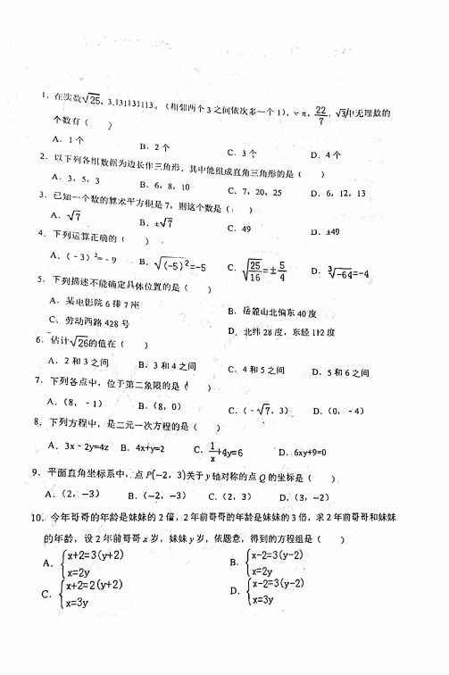
上学期期中模拟考试01八年级数学(湘教版:第1-3章)(考试时间:120分钟试卷满分:120分)第Ⅰ卷一、选择题:本题共10小题,每小题3分,共30分。
1.实数9的算术平方根是()A .3B .±3C .D .﹣92.代数式25x ,1,22+4,x 2−23,1,+1+2中,属于分式的有()A .2个B .3个C .4个D .5个3.已知x =1是方程2−−1K 2=3的解,那么实数m 的值为()A .﹣2B .2C .﹣4D .44.如图1所示,将长为6的矩形纸片沿虚线折成3个矩形,其中左右两侧矩形的宽相等,若要将其围成如图2所示的三棱柱形物体,则图中a 的值可以是()A .1B .2C .3D .45.若等腰三角形有一个内角为110°,则这个等腰三角形的底角是()A .70°B .45°C .35°D .50°6.如图,CD ⊥AB 于点D ,已知∠ABC 是钝角,则()A .线段CD 是△ABC 的AC 边上的高线B .线段CD 是△ABC 的AB 边上的高线C .线段AD 是△ABC 的BC 边上的高线D .线段AD 是△ABC 的AC 边上的高线7.下列说法正确的是()A .命题一定有逆命题B .所有的定理一定有逆定理C.真命题的逆命题一定是真命题D.假命题的逆命题一定是假命题8.如图,点D、E分别在线段BC、AC上,连接AD、BE.若∠A=35°,∠B=25°,∠C=50°,则∠1的大小为()A.60°B.70°C.75°D.85°9.已知一列均不为1的数a1,a2,a3,…,a n满足如下关系:a2=1+11−1,a3=1+21−2,4=1+31−3,+1=1+1−,若a1=2,则a2023的值是()A.−12B.13C.﹣3D.210.某运输公司运输一批货物,已知大货车比小货车每辆多运输5吨货物,且大货车运输75吨货物所用车辆数与小货车运输50吨货物所用车辆数相同,设大货车每辆运输x吨,则所列方程正确的是()A.75 K5=50B.75=50K5C.75+5=50D.75=50+5第Ⅱ卷二、填空题:本题共6小题,每小题3分,共18分。

人教版七年级英语上册Starter Units 综合素质评价(限时: 120分钟满分: 120分)第一部分(听力共30 分)I. 听选答案(共15 小题, 计20 分)第一节: 听下面10 段对话,每段对话后有一个问题, 读两遍。
请根据每段对话的内容和后面的问题, 从所给的三个选项中选出问题的正确答案。
(共10 小题, 计10 分)( ) 1. A. Red. B. White. C. Green.( ) 2. A. Kate’s hat. B. Kate’s cup. C. Kate’s pen. ( ) 3. A. It is morning. B. It is afternoon. C. It is evening. ( ) 4. A. Paul. B. Bruce. C. Grace.( ) 5. A. Boxes. B. Books. C. Balls.( ) 6. A. A pen. B. A pencil. C. A pencil case. ( ) 7. A. Ducks. B. Geese. C. Rabbits.( ) 8. A. Her bag. B. Her eraser. C. Her book. ( ) 9. A. It’s on the box. B. It’s behind the box. C. It’s under the box. ( ) 10. A. The keys. B. The CDs. C. The books.第二节: 听下面两段材料, 包括一篇独白和一段对话,每段材料后有几道小题。
请根据材料的内容, 从题目所给的三个选项中选出问题的正确答案。
每段材料读两遍。
(共5 小题, 计10 分)听第1 段材料, 回答第11、12 小题。
( ) 11. What colour is the ruler?A. Green.B. White.C. Red.( ) 12. What is Helen’s?A. The bottle.B. The pen.C. The ruler.听第2 段材料, 回答第13 至15 小题。


2022-2023学年人教版七年级下学期期末数学几何解答题专题练习1、如图,AB∥CD,∠A=∠C,BE平分∠ABC交AD的延长线于点E,(1)证明:AD∥BC;(2)若∠ADC=118°,求∠E的度数.2、如图,已知∠1=∠BDC,∠2+∠3=180°.(1)AD与EC平行吗?试说明理由.(2)若DA平分∠BDC,CE⊥AE于点E,∠1=80°,试求∠F AB的度数.3、小聪把一副三角尺ABC,DCE按如图1的方式摆放,其中边BC,DC在同一条直线上,过点A向右作射线AP∥DE.(1)如图2,求∠P AC的度数;(2)如图3,点Q是线段BC上一点,若∠AQB=53∠PAQ,求∠QAB的度数.4、已知:在四边形ABCD中,AD∥BC,AE平分∠DAB交BC于点E,点M为线段BC上一点,且AM∥DC.(1)如图(1),若点M与点E重合,求证:∠C=∠BAE;(2)如图(2),若AN平分∠BAM交BC于点N,且∠NAE=25°,求∠C的度数;(3)在(1)的条件下,F为线段BA的延长线上一点,∠DCB=75°,若∠DCB的三等分线与∠F AD的角平分线交于点P,请直接写出∠APC的度数.5、直线AB∥CD,BE﹣EC是一条折线段,BP平分∠ABE.(1)如图1,若BP∥CE,求证:∠BEC+∠DCE=180°;(2)CQ平分∠DCE,直线BP,CQ交于点F.①如图2,写出∠BEC和∠BFC的数量关系,并证明;②当点E在直线AB,CD之间时,若∠BEC=40°,直接写出∠BFC的大小.6、如图1,AB∥CD,点E在AB上,点H在CD上,点F在直线AB,CD之间,连接EF,FH,∠BEF=α,∠FHD=β.(1)直接写出∠EFH的度数为;(2)如图2,若HM平分∠CHF,MN平分∠BEF,证明:∠EFH+2∠M=180°;(3)如图3,若∠BEN=1n∠BEF,∠MHC=1n∠FHC,则∠M=.(用含有n,α,β的式子表示)7、如图,已知A(0,a),B(b,0),且满足|a−4|+√b+6=0.(1)求A、B两点的坐标;(2)点P(m,n)在线段AB上,当PB=2P A时,求P点的坐标;(3)若点M(c,6),△ABM的面积记作S△ABM,当S△ABM>10时,直接写出c的取值范围.8、在平面直角坐标系中,已知点A(a,0),B(0,b),若a,b满足(a﹣b+6)2+|2a﹣3b+14|=0.(1)求点A,B的坐标;(2)将线段AB向右平移2个单位至CD,线段CD与y轴交于点E,求点E的坐标;(3)点P为直线CD上一动点,连接BC,PB,若4≤S△BCP<6,则点P的横坐标x P的取值范围是.9、如图,已知AB∥CD,M,N分别是直线AB,CD上一点,点E在直线AB,CD之间.(1)如图1,求证:∠BME+∠DNE=∠MEN;(2)如图2,F是EM上一点,NE平分∠FND,FH平分∠NFE,试探究∠NHF与∠BME 之间的数量关系?并证明你的结论;(3)如图3,P为直线MN上一动点(不与点N重合),过点P作PG⊥MN交直线CD 于点G,∠PNG的角平分线和∠PGC的角平分线交于点O,则∠O的度数为(直接写出结果).10、平面直角坐标系中,A(a,0),B(0,b),a,b均为整数,且满足b=√2a−4−√4−a,点C在y轴负半轴上且S△ABC=10,将线段AB平移到DE,其中点A的对应点是点D.(1)请直接写出点A ,B ,C 的坐标;(2)如图(1),若点D 的坐标为(﹣1,0),点F (m ,n )为线段DE 上一点,且△ACF 的面积大于12,求m 的取值范围;(3)如图(2),若DE 与y 轴的交点G 在B 点上方,点P 为y 轴上一动点,请直接写出∠EBO ,∠BPD ,∠PDA 之间的数量关系.11、在平面直角坐标系中,A (a ,0),B (1,b ),a ,b 满足|a +b ﹣1|+√2a −b +10=0,连接AB 交y 轴于C .(1)直接写出a = ,b = ;(2)如图1,点P 是y 轴上一点,且三角形ABP 的面积为12,求点P 的坐标;(3)如图2,直线BD 交x 轴于D (4,0),将直线BD 平移经过点A ,交y 轴于E ,点Q (x ,y )在直线AE 上,且三角形ABQ 的面积不超过三角形ABD 面积的13,求点Q 横坐标x 的取值范围.12、已知,AB ∥DE ,点C 是直线AB ,DE 下方一点,连接BC ,DC .(1)如图1,求证:∠B +∠D ﹣∠C =180°;(2)如图2,若BF ,DG 分别平分∠ABC 和∠CDE ,BF 、DG 所在的直线相交于点H ,若∠H =α°,求∠C 的度数;(用含α的式子表示)(3)如图3,若BF ,DG 分∠ABC 和∠CDE 为两部分,且∠ABF =n ∠FBC ,∠EDG =n ∠CDG ,直线BF ,DG 相交于点H ,则∠H = .(用含n 和∠C 的式子表示)13、已知,在平面直角坐标系中,点A 在y 轴上,OA =a ,点B (b ,b ),且a 、b 满足√a +b −8+(a −b −4)2=0.(1)则a = ;b = ;(2)如图1,在x 轴上是否存在点C ,使三角形ABC 的面积等于三角形ABO 面积的一半?若存在,请求出点C 的坐标;若不存在,请说明理由;(3)如图2,将线段AB 向左平移m 个单位(m >0),得到线段A 'B ',其中点A ,点B 的对应点分别为点A ',点B '.若点N (﹣1,n )在射线A 'B '上,连接ON ,BN 得到三角形BON ,若三角形BON 的面积大于三角形ABO 面积的12并且小于三角形ABO 面积,则m 的取值范围是 .14、如图1,已知点A (﹣2,0),B (0,﹣4),C (﹣4,﹣6),过点C 作x 轴的平行线m ,一动点P 从C 点出发,在直线m 上以1个单位长度/秒的速度向右运动,与此同时,直线m 以2个单位长度/秒的速度竖直向上运动.(1)直接写出:运动1秒时,点P 的坐标为 ;运动t 秒时,点P 的坐标为 ;(用含t 的式子表示)(2)若点P 在第三象限,且S △ABP =8,求点P 的坐标;(3)如图2,如果将直线AB 沿y 轴负半轴向下平移n 个单位长度,恰好经过点C ,求n 的值.15、已知BE 平分∠ABD ,DE 平分∠BDC ,且∠BED =∠ABE +∠EDC .(1)如图1,求证:AB ∥CD ;(2)如图2,若∠ABE =3∠ABF ,且∠BFD =30°时,试求∠CDF ∠FDE 的值;(3)如图3,若H 是直线CD 上一动点(不与D 重合),BI 平分∠HBD ,画出图形,并探究出∠EBI 与∠BHD 的数量关系.问题探究:(1)如图1,∠CFP +∠EPF =∠AEP ,证明:AB ∥CD ;问题拓展:(2)如图2,AB ∥CD ,∠AEP 的角平分线EK 所在的直线和∠DFP 的角平分线FR 所在的直线交于Q 点,请写出∠EPF 和∠EQF 之间的数量关系,并证明.问题迁移:(3)如图3,AB ∥CD ,直线MN 分别交AB ,CD 于点M ,N ,若点H 在线段MN 上,且∠MEF =α,请直接写出∠HFE ,∠MEH 和∠EHF 之间满足的数量关系(用含α的式子表示).16、当光线经过镜面反射时,入射光线、反射光线与镜面所夹的角对应相等例如:在图①、图②中,都有∠1=∠2,∠3=∠4.设镜子AB 与BC 的夹角∠ABC =α.(1)如图①,若α=90°,判断入射光线EF 与反射光线GH 的位置关系,并说明理由.(2)如图②,若90°<α<180°,入射光线EF 与反射光线GH 的夹角∠FMH =β.探索α与β的数量关系,并说明理由.(3)如图③,若α=120°,设镜子CD 与BC 的夹角∠BCD =γ(90°<γ<180°),入射光线EF 与镜面AB 的夹角∠1=m (0°<m <90°),已知入射光线EF 从镜面AB 开始反射,经过n (n 为正整数,且n ≤3)次反射,当第n 次反射光线与入射光线EF 平行时,请直接写出γ的度数.(可用含有m 的代数式表示)17、在平面直角坐标系中,点A ,C 均在x 轴上,点B 在第一象限,直线AB 上所有点的坐标(x ,y )都是二元一次方程x ﹣y =﹣2的解,直线BC 上所有点的坐标(x ,y )都是二元一次方程2x +y =8的解.(1)求B 点的坐标时,小明是这样想的:先设B 点坐标为(m ,n ),因为B 点在直线AB 上,所以(m ,n )是方程x ﹣y =﹣2的解;又因为B 点在直线BC 上,所以(m ,n )也是方程2x +y =8的解,从而m ,n 满足{m −n =−22m +n =8.据此可求出B 点坐标为 ,再求出A 点坐标为 ;C 点坐标为 .(均直接写出结果)(2)若线段BC 上存在一点D ,使S △OCD =12S △ABC (O 为原点),求D 点坐标;(3)点E (a ,﹣3)是坐标平面内的动点,若满足S △ABE ≤13S △ABC ,求a 的取值范围.18、已知:点E 在直线AB 上,点F 在直线CD 上,AB ∥CD .(1)如图1,连EF ,EP 平分∠AEF ,FP 平分∠CFE ,求∠P 的度数.(2)如图2,若∠EGF =160°,射线EH ,FH 分别在∠AEG ,∠CFG 的内部,且∠EHF =40°,当∠AEG =4∠AEH 时,求∠GFH ∠CFG 的值.(3)如图3,在(1)的条件下,在直线CD 上有一动点M (点M 不与点F 重合),EN 平分∠MEF ,若∠PEN =α(0°<α<90°),请直接写出∠EMF = (结果用含α的式子表示).19、在平面直角坐标系中,A (a ,0),B (b ,b ),C (0,c ).(其中a ,b ,c 均为正数),且a ,b ,c 满足{3a −b +2c =8a −2b −c =−9,若√b 的算术平方根为√2. (1)求a ,b ,c 的值.(2)如图1,在第二象限内有一点P (m ,12),若四边形ACPO 的面积与△ABC 的面积相等,求不等式:x−32≥2x−m 3的解集.(3)如图2,BO 平分∠AOC ,过点C 作CD ∥AB 交BO 的延长线于点D ,AE 平分∠BAX ,AE 的反向延长线交BO 的延长线于点F ,设∠CDB =α,∠F =β(其中α,β均为锐角),请直接写出:α+2β3= .23.(10分)如图1,已知直线l1∥l2,点A、B在直线l1上,点C、D在l2上,线段AD交线段BC于点E,且∠BED=60°.(1)求证:∠ABE+∠EDC=60°;(2)如图2,当F、G分别在线段AE、EC上,且∠ABF=2∠FBE,∠EDG=2∠GDC,标记∠BFE为∠1,∠BGD为∠2.①若∠1﹣∠2=16°,求∠ADC的度数;②当k=时,(k∠1+∠2)为定值,此时定值为.24.(12分)如图1,在平面直角坐标系中,已知A(a,1),B(0,b),且实数a,b满足√a+b−2+|a+2b|=0.(1)直接写出两点坐标:A(),B();(2)如图2,将线段AB沿着横坐标均为m的点组成的直线l对折,A与C对应,B与D 对应,若凸四边形ABDC的面积为18,求m的值;(3)如图3,点P在第二、四象限的角平分线上,设P点坐标为(h,﹣h),其中h≠0.①当P在线段AB上时,求h的值;②若S△ABP≥2+32S△OBP.直接写出h的取值范围.。

Preliminary datasheetEasyPIM ™ 模块 采用第七代沟槽栅/场终止IGBT7和第七代发射极控制二极管带有温度检测NTC 特性•电气特性-沟槽栅IGBT7-过载操作达175°C -低 V CEsat •机械特性-焊接技术-紧凑型设计-高功率密度-低热阻的三氧化二铝 Al 2O 3 衬底-2.5 kV 交流 1分钟 绝缘可选应用•空调•辅助逆变器•电机传动产品认证•根据 IEC 60747、60749 和 60068 标准的相关测试,符合工业应用的要求。
描述FP10R12W1T7EasyPIM ™ 模块内容描述 . . . . . . . . . . . . . . . . . . . . . . . . . . . . . . . . . . . . . . . . . . . . . . . . . . . . . . . . . . . . . . . . . . . . . . . . . . . . . . . . . . . . . . . . .1特性 . . . . . . . . . . . . . . . . . . . . . . . . . . . . . . . . . . . . . . . . . . . . . . . . . . . . . . . . . . . . . . . . . . . . . . . . . . . . . . . . . . . . . . . . .1可选应用 . . . . . . . . . . . . . . . . . . . . . . . . . . . . . . . . . . . . . . . . . . . . . . . . . . . . . . . . . . . . . . . . . . . . . . . . . . . . . . . . . . . .1产品认证 . . . . . . . . . . . . . . . . . . . . . . . . . . . . . . . . . . . . . . . . . . . . . . . . . . . . . . . . . . . . . . . . . . . . . . . . . . . . . . . . . . . .1内容 . . . . . . . . . . . . . . . . . . . . . . . . . . . . . . . . . . . . . . . . . . . . . . . . . . . . . . . . . . . . . . . . . . . . . . . . . . . . . . . . . . . . . . . . .2 1封装 . . . . . . . . . . . . . . . . . . . . . . . . . . . . . . . . . . . . . . . . . . . . . . . . . . . . . . . . . . . . . . . . . . . . . . . . . . . . . . . . . . . . . . . . .3 2IGBT, 逆变器 . . . . . . . . . . . . . . . . . . . . . . . . . . . . . . . . . . . . . . . . . . . . . . . . . . . . . . . . . . . . . . . . . . . . . . . . . . . . . . . . .3 3二极管,逆变器 . . . . . . . . . . . . . . . . . . . . . . . . . . . . . . . . . . . . . . . . . . . . . . . . . . . . . . . . . . . . . . . . . . . . . . . . . . . . . . .5 4二极管,整流器 . . . . . . . . . . . . . . . . . . . . . . . . . . . . . . . . . . . . . . . . . . . . . . . . . . . . . . . . . . . . . . . . . . . . . . . . . . . . . . .6 5IGBT, 制动-斩波器 . . . . . . . . . . . . . . . . . . . . . . . . . . . . . . . . . . . . . . . . . . . . . . . . . . . . . . . . . . . . . . . . . . . . . . . . . . . .7 6二极管,制动-斩波器 . . . . . . . . . . . . . . . . . . . . . . . . . . . . . . . . . . . . . . . . . . . . . . . . . . . . . . . . . . . . . . . . . . . . . . . . .8 7负温度系数热敏电阻 . . . . . . . . . . . . . . . . . . . . . . . . . . . . . . . . . . . . . . . . . . . . . . . . . . . . . . . . . . . . . . . . . . . . . . . . .9 8特征参数图表 . . . . . . . . . . . . . . . . . . . . . . . . . . . . . . . . . . . . . . . . . . . . . . . . . . . . . . . . . . . . . . . . . . . . . . . . . . . . . . .10 9电路拓扑图 . . . . . . . . . . . . . . . . . . . . . . . . . . . . . . . . . . . . . . . . . . . . . . . . . . . . . . . . . . . . . . . . . . . . . . . . . . . . . . . . .16 10封装尺寸 . . . . . . . . . . . . . . . . . . . . . . . . . . . . . . . . . . . . . . . . . . . . . . . . . . . . . . . . . . . . . . . . . . . . . . . . . . . . . . . . . . .17 11模块标签代码 . . . . . . . . . . . . . . . . . . . . . . . . . . . . . . . . . . . . . . . . . . . . . . . . . . . . . . . . . . . . . . . . . . . . . . . . . . . . . . .18免责声明 . . . . . . . . . . . . . . . . . . . . . . . . . . . . . . . . . . . . . . . . . . . . . . . . . . . . . . . . . . . . . . . . . . . . . . . . . . . . . . . . . . .191封装表 1绝缘参数特征参数代号标注或测试条件数值单位绝缘测试电压V ISOL RMS, f = 50 Hz, t = 1 min 2.5kV 内部绝缘基本绝缘 (class 1, IEC 61140)Al2O3爬电距离d Creep端子至散热器11.5mm 爬电距离d Creep端子至端子 6.3mm 电气间隙d Clear端子至散热器10.0mm 电气间隙d Clear端子至端子 5.0mm 相对电痕指数CTI > 200相对温度指数 (电)RTI住房140°C 表 2特征值特征参数代号标注或测试条件数值单位最小值典型值最大值杂散电感,模块L sCE30nH 模块引线电阻,端子-芯片R AA'+CC'T H=25°C, 每个开关6mΩ模块引线电阻,端子-芯片R CC'+EE'T H=25°C, 每个开关8mΩ储存温度T stg-40125°C Mounting force per clamp F2050N 重量G24g注:The current under continuous operation is limited to 30A rms per connector pin.2IGBT, 逆变器表 3最大标定值特征参数代号标注或测试条件数值单位集电极-发射极电压V CES T vj = 25 °C1200V 连续集电极直流电流I CDC T vj max = 175 °C T H = 100 °C10A 集电极重复峰值电流I CRM t P = 1 ms20A 栅极-发射极峰值电压V GES±20V表 4特征值特征参数代号标注或测试条件数值单位最小值典型值最大值集电极-发射极饱和电压V CE sat I C = 10 A, V GE = 15 V T vj = 25 °C 1.60TBD VT vj = 125 °C 1.74T vj = 175 °C 1.82栅极阈值电压V GEth I C = 0.22 mA, V CE = V GE, T vj = 25 °C 5.15 5.80 6.45V 栅极电荷Q G V GE = ±15 V, V CE = 600 V0.157µC 内部栅极电阻R Gint T vj = 25 °C0Ω输入电容C ies f = 100 kHz, T vj = 25 °C, V CE = 25 V, V GE = 0 V 1.89nF 反向传输电容C res f = 100 kHz, T vj = 25 °C, V CE = 25 V, V GE = 0 V0.0066nF 集电极-发射极截止电流I CES V CE = 1200 V, V GE = 0 V T vj = 25 °C0.0045mA 栅极-发射极漏电流I GES V CE = 0 V, V GE = 20 V, T vj = 25 °C100nA开通延迟时间(感性负载)t don I C = 10 A, V CE = 600 V,V GE = ±15 V, R Gon = 8.2 ΩT vj = 25 °C0.023µs T vj = 125 °C0.025T vj = 175 °C0.026上升时间(感性负载)t r I C = 10 A, V CE = 600 V,V GE = ±15 V, R Gon = 8.2 ΩT vj = 25 °C0.014µs T vj = 125 °C0.017T vj = 175 °C0.019关断延迟时间(感性负载)t doff I C = 10 A, V CE = 600 V,V GE = ±15 V, R Goff = 8.2 ΩT vj = 25 °C0.124µs T vj = 125 °C0.157T vj = 175 °C0.176下降时间(感性负载)t f I C = 10 A, V CE = 600 V,V GE = ±15 V, R Goff = 8.2 ΩT vj = 25 °C0.227µs T vj = 125 °C0.347T vj = 175 °C0.422开通损耗能量 (每脉冲)E on I C = 10 A, V CE = 600 V,Lσ = 35 nH, V GE = ±15 V,R Gon = 8.2 Ω, di/dt = 550A/µs (T vj = 175 °C)T vj = 25 °C0.73mJ T vj = 125 °C0.94T vj = 175 °C 1.13关断损耗能量 (每脉冲)E off I C = 10 A, V CE = 600 V,Lσ = 35 nH, V GE = ±15 V,R Goff = 8.2 Ω, dv/dt =2700 V/µs (T vj = 175 °C)T vj = 25 °C0.623mJ T vj = 125 °C0.97T vj = 175 °C 1.17表 4特征值 (continued)特征参数代号标注或测试条件数值单位最小值典型值最大值短路数据I SC V GE≤ 15 V, V CC = 800 V,V CEmax=V CES-L sCE*di/dt t P≤ 8 µs,T vj = 150 °C32At P≤ 7 µs,T vj = 175 °C30结-散热器热阻R thJH每个 IGBT 2.05K/W 允许开关的温度范围T vj op-40175°C注:T vj op > 150°C is allowed for operation at overload conditions. For detailed specifications, please refer to AN 2018-14.3二极管,逆变器表 5最大标定值特征参数代号标注或测试条件数值单位反向重复峰值电压V RRM T vj = 25 °C1200V 连续正向直流电流I F10A 正向重复峰值电流I FRM t P = 1 ms20A I2t-值I2t V R = 0 V, t P = 10 ms T vj = 125 °C27.5A²sT vj = 175 °C24表 6特征值特征参数代号标注或测试条件数值单位最小值典型值最大值正向电压V F I F = 10 A, V GE = 0 V T vj = 25 °C 1.72TBD VT vj = 125 °C 1.59T vj = 175 °C 1.52反向恢复峰值电流I RM I F = 10 A, V R = 600 V,V GE = -15 V, -di F/dt = 550A/µs (T vj = 175 °C)T vj = 25 °C10.5A T vj = 125 °C15.3T vj = 175 °C17.5恢复电荷Q r I F = 10 A, V R = 600 V,V GE = -15 V, -di F/dt = 550A/µs (T vj = 175 °C)T vj = 25 °C0.97µC T vj = 125 °C 1.7T vj = 175 °C 2.2表 6特征值 (continued)特征参数代号标注或测试条件数值单位最小值典型值最大值反向恢复损耗(每脉冲)E rec I F = 10 A, V R = 600 V,V GE = -15 V, -di F/dt = 550A/µs (T vj = 175 °C)T vj = 25 °C0.24mJ T vj = 125 °C0.51T vj = 175 °C0.72结-散热器热阻R thJH每个二极管 2.45K/W 允许开关的温度范围T vj op-40175°C注:T vj op > 150°C is allowed for operation at overload conditions. For detailed specifications, please refer to AN 2018-14.4二极管,整流器表 7最大标定值特征参数代号标注或测试条件数值单位反向重复峰值电压V RRM T vj = 25 °C1600V 最大正向均方根电流(每芯片)I FRMSM T H = 100 °C25A 最大整流器输出均方根电流I RMSM T H = 100 °C25A 正向浪涌电流I FSM t P = 10 ms T vj = 25 °C300AT vj = 150 °C245I2t-值I2t t P = 10 ms T vj = 25 °C450A²sT vj = 150 °C300表 8特征值特征参数代号标注或测试条件数值单位最小值典型值最大值正向电压V F I F = 10 A T vj = 150 °C0.80V 反向电流I r T vj = 150 °C, V R = 1600 V1mA 结-散热器热阻R thJH每个二极管 1.54K/W 允许开关的温度范围T vj, op-40150°C5IGBT, 制动-斩波器表 9最大标定值特征参数代号标注或测试条件数值单位集电极-发射极电压V CES T vj = 25 °C1200V 连续集电极直流电流I CDC T vj max = 175 °C T H = 100 °C10A 集电极重复峰值电流I CRM t P = 1 ms20A 栅极-发射极峰值电压V GES±20V表 10特征值特征参数代号标注或测试条件数值单位最小值典型值最大值集电极-发射极饱和电压V CE sat I C = 10 A, V GE = 15 V T vj = 25 °C 1.60TBD VT vj = 125 °C 1.74T vj = 175 °C 1.82栅极阈值电压V GEth I C = 0.22 mA, V CE = V GE, T vj = 25 °C 5.15 5.80 6.45V 栅极电荷Q G V GE = ±15 V, V CE = 600 V0.157µC 内部栅极电阻R Gint T vj = 25 °C0Ω输入电容C ies f = 100 kHz, T vj = 25 °C, V CE = 25 V, V GE = 0 V 1.89nF 反向传输电容C res f = 100 kHz, T vj = 25 °C, V CE = 25 V, V GE = 0 V0.0066nF 集电极-发射极截止电流I CES V CE = 1200 V, V GE = 0 V T vj = 25 °C0.0045mA 栅极-发射极漏电流I GES V CE = 0 V, V GE = 20 V, T vj = 25 °C100nA开通延迟时间(感性负载)t don I C = 10 A, V CE = 600 V,V GE = ±15 V, R Gon = 8.2 ΩT vj = 25 °C0.023µs T vj = 125 °C0.025T vj = 175 °C0.026上升时间(感性负载)t r I C = 10 A, V CE = 600 V,V GE = ±15 V, R Gon = 8.2 ΩT vj = 25 °C0.014µs T vj = 125 °C0.017T vj = 175 °C0.019关断延迟时间(感性负载)t doff I C = 10 A, V CE = 600 V,V GE = ±15 V, R Goff = 8.2 ΩT vj = 25 °C0.124µs T vj = 125 °C0.157T vj = 175 °C0.176下降时间(感性负载)t f I C = 10 A, V CE = 600 V,V GE = ±15 V, R Goff = 8.2 ΩT vj = 25 °C0.227µs T vj = 125 °C0.347T vj = 175 °C0.422表 10特征值 (continued)特征参数代号标注或测试条件数值单位最小值典型值最大值开通损耗能量 (每脉冲)E on I C = 10 A, V CE = 600 V,Lσ = 35 nH, V GE = ±15 V,R Gon = 8.2 Ω, di/dt = 550A/µs (T vj = 175 °C)T vj = 25 °C0.73mJ T vj = 125 °C0.94T vj = 175 °C 1.13关断损耗能量 (每脉冲)E off I C = 10 A, V CE = 600 V,Lσ = 35 nH, V GE = ±15 V,R Goff = 8.2 Ω, dv/dt =2700 V/µs (T vj = 175 °C)T vj = 25 °C0.623mJ T vj = 125 °C0.97T vj = 175 °C 1.17短路数据I SC V GE≤ 15 V, V CC = 800 V,V CEmax=V CES-L sCE*di/dt t P≤ 8 µs,T vj = 150 °C32At P≤ 7 µs,T vj = 175 °C30结-散热器热阻R thJH每个 IGBT 2.05K/W 允许开关的温度范围T vj op-40175°C注:T vj op > 150°C is allowed for operation at overload conditions. For detailed specifications, please refer to AN 2018-14.6二极管,制动-斩波器表 11最大标定值特征参数代号标注或测试条件数值单位反向重复峰值电压V RRM T vj = 25 °C1200V 连续正向直流电流I F10A 正向重复峰值电流I FRM t P = 1 ms20A I2t-值I2t V R = 0 V, t P = 10 ms T vj = 125 °C27.5A²sT vj = 175 °C24表 12特征值特征参数代号标注或测试条件数值单位最小值典型值最大值正向电压V F I F = 10 A, V GE = 0 V T vj = 25 °C 1.72TBD VT vj = 125 °C 1.59T vj = 175 °C 1.52表 12特征值 (continued)特征参数代号标注或测试条件数值单位最小值典型值最大值反向恢复峰值电流I RM I F = 10 A, V R = 600 V,-di F/dt = 550 A/µs(T vj = 175 °C)T vj = 25 °C10.5A T vj = 125 °C15.3T vj = 175 °C17.5恢复电荷Q r I F = 10 A, V R = 600 V,-di F/dt = 550 A/µs(T vj = 175 °C)T vj = 25 °C0.97µC T vj = 125 °C 1.7T vj = 175 °C 2.2反向恢复损耗(每脉冲)E rec I F = 10 A, V R = 600 V,-di F/dt = 550 A/µs(T vj = 175 °C)T vj = 25 °C0.24mJ T vj = 125 °C0.51T vj = 175 °C0.72结-散热器热阻R thJH每个二极管 2.45K/W 允许开关的温度范围T vj op-40175°C注:T vj op > 150°C is allowed for operation at overload conditions. For detailed specifications, please refer to AN 2018-14.7负温度系数热敏电阻表 13特征值特征参数代号标注或测试条件数值单位最小值典型值最大值额定电阻值R25T NTC = 25 °C5kΩR100偏差ΔR/R T NTC = 100 °C, R100 = 493 Ω-55%耗散功率P25T NTC = 25 °C20mW B-值B25/50R2 = R25 exp[B25/50(1/T2-1/(298,15 K))]3375K B-值B25/80R2 = R25 exp[B25/80(1/T2-1/(298,15 K))]3411K B-值B25/100R2 = R25 exp[B25/100(1/T2-1/(298,15 K))]3433K 注:根据应用手册标定7 负温度系数热敏电阻9电路拓扑图图 210封装尺寸图 311 模块标签代码11模块标签代码图 4商标所有参照产品或服务名称和商标均为其各自所有者的财产。

V CES V GESI CI CP -I C-I C pulse P C V CES V GES I C I CPP C V RRM V RRM I O I FSM I 2t T j T stg V iso Operating junction temperatureStorage temperatureIsolation between terminal and copper base *2voltage between thermistor and others *3Mounting screw torque7MBR50UA120IGBT ModulesIGBT MODULE (U series)1200V / 50A / PIMFeatures· Low V CE (sat)· Compact Package· P .C. Board Mount Module· Converter Diode Bridge Dynamic Brake CircuitApplications· Inverter for Motoe Drive· AC and DC Servo Drive Amplifier · Uninterruptible Power SupplyMaximum ratings and characteristicsItem Symbol Condition Rating UnitCollector-Emitter voltage Gate-Emitter voltage Collector current Collector power disspation Collector-Emitter voltage Gate-Emitter voltage Collector currentCollector power disspationRepetitive peak reverse voltage Repetitive peak reverse voltage Average output currentSurge current (Non-Repetitive)I 2t (Non-Repetitive)C o n v e r t e r B r a k e I n v e r t e rContinuous 1ms Duty=70%1ms 1 deviceContinuous 1ms 1 device50Hz/60Hz sine wave Tj=150°C, 10ms half sine waveAC : 1 minute1200 ±20 50 35 100 70 50 100 205 1200 ±20 25 15 50 30 115 1200 1600 50 260 338 +150-40 to +125 AC 2500 AC 2500 3.5 *1V V A W V V AW V V A A A 2s °C °C V N·m*1 Recommendable value : 2.5 to 3.5 N·m (M5)*2 All terminals should be connected together when isolation test will be done.*3 Two thermistor terminals should be connected together, each other terminals should be connected together and shorted to base plate when isolation test will be done.Tc=25°C Tc=80°CTc=25°C Tc=80°CTc=25°C Tc=80°C Tc=25°C Tc=80°CIGBT Module7MBR50UA120Equivalent Circuit Schematic89[Thermistor][Converter]21(P)23(N)24(N1)IGBT Module7MBR50UA120Characteristics (Representative)Vcc=600V, Ic=50A, Tj= 25°CVGE=0V, f= 1MHz, Tj= 25°CCapacitance vs. Collector-Emitter voltage (typ.)Dynamic Gate charge (typ.)Collector current vs. Collector-Emitter voltage (typ.)Tj= 25°C / chipCollector current vs. Collector-Emitter voltage (typ.)VGE=15V / chipTj=25°C / chip[ Inverter ][ Inverter ]Collector-Emitter voltage vs. Gate-Emitter voltage (typ.)[ Inverter ][ Inverter ][ Inverter ][ Inverter ]Collector current vs. Collector-Emitter voltage (typ.)Tj= 125°C / chip025507510012345C o l l e c t o r c u r r e n t : I c [A ]Collector-Emitter voltage : VCE [V]VGE=20V 15V 12V10V8V255075100012345C o l l e c t o r c u r r e n t : I c [A ]Collector-Emitter voltage : VCE [V]VGE=20V 15V12V10V8V025507510012345C o l l e c t o r c u r r e n t : I c [A ]Collector-Emitter voltage : VCE [V]Tj=125°CTj=25°C0246810510152025C o l l e c t o r - E m i t t e r v o l t a g e : V C E [ V ]Gate - Emitter voltage : VGE [ V ]Ic=70A Ic=35A Ic=17.5A0.11.010.0102030C a p a c i t a n c e : C i e s , C o e s , C r e s [ n F ]Collector-Emitter voltage : VCE [V]50100150200C o l l e c t o r -E m i t t e r v o l t a g e : V C E [ 200V /d i v ]G a t e - E m i t t e r v o l t a g e : V G E [ 5V /d i v ]Gate charge : Qg [ nC ]IGBT Module7MBR50UA120Switching time vs. Gate resistance (typ.)Vcc=600V, VGE=±15V, Rg=33ΩSwitching loss vs. Gate resistance (typ.)[ Inverter ][ Inverter ]Vcc=600V, Ic=50A, VGE=±15V, Tj= 25°CSwitching loss vs. Collector current (typ.)+VGE=15V,-VGE <= 15V, RG >= 33Ω ,Tj <= 125°CReverse bias safe operating area (max.)Vcc=600V, Ic=50A, VGE=±15V, Tj= 125°C[ Inverter ][ Inverter ][ Inverter ][ Inverter ]Switching time vs. Collector current (typ.)Vcc=600V, VGE=±15V, Rg=33Ω, Tj= 25°CSwitching time vs. Collector current (typ.)Vcc=600V, VGE=±15V, Rg=33Ω, Tj=125°C1010010001000010203040506070S w i t c h i n g t i m e : t o n , t r , t o f f , t f [ n s e c ]Collector current : Ic [ A ]1010010001000010203040506070S w i t c h i n g t i m e : t o n , t r , t o f f , t f [ n s e c ]Collector current : Ic [ A ]1010010001000010.0100.01000.0S w i t c h i n g t i m e : t o n , t r , t o f f , t f [ n s e c ]Gate resistance : Rg [ Ω ]tr tftoffton 048121620102030405060708090S w i t c h i n g l o s s : E o n , E o f f , E r r [ m J /p u l s e ]Collector current : Ic [ A ]Eon(125°C)Eon(25°C)Eoff(125°C)Err(125°C)Err(25°C)Eoff(25°C)01020301.010.0100.01000.0S w i t c h i n g l o s s : E o n , E o f f , E r r [ m J /p u l s e ]Gate resistance : Rg [ Ω ]Eoff ErrEon0501001504008001200C o l l e c t o r c u r r e n t : I c [ A ]Collector - Emitter voltage : VCE [ V ]IGBT Module7MBR50UA120[ Inverter ][ Inverter ][ Thermistor ]Reverse recovery characteristics (typ.)Vcc=600V, VGE=±15V, Rg=33ΩForward current vs. Forward on voltage (typ.)chipchip[ Converter ]Forward current vs. Forward on voltage (typ.)Temperature characteristic (typ.)Transient thermal resistance (max.)0.1110100-60-40-2020406080100120140160180Temperature [°C ]R e s i s t a n c e : R [ k Ω ]02550751234F o r w a r d c u r r e n t : I F [ A ]Forward on voltage : VF [ V ]T j=125°CT j=25°C10100100010203040506070R e v e r s e r e c o v e r y c u r r e n t : I r r [ A ]R e v e r s e r e c o v e r y t i m e : t r r [ n s e c ]Forward current : IF [ A ]trr (125°C)trr (25°C)Irr (125°C)Irr (25°C)0.0100.1001.00010.0000.0010.0100.100 1.000T h e r m a l r e s i s t a n s e : R t h (j -c ) [ °C /W ]Pulse width : Pw [ sec ]FWD[Inverter]IGBT[Brake]IGBT[Inverter]02550750.00.51.01.52.02.5F o r w a r d c u r r e n t : I F [ A ]Forward on voltage : VFM [ V ]T j=125°CT j=25°CConv.DiodeVcc=600V, Ic=25A, Tj= 25°CDynamic Gate charge (typ.)VGE=0V, f= 1MHz, Tj= 25°CCapacitance vs. Collector-Emitter voltage (typ.)Tj=25°C / chip[ Brake ][ Brake ]Collector-Emitter voltage vs. Gate-Emitter voltage (typ.)Collector current vs. Collector-Emitter voltage (typ.)VGE=15V / chip[ Brake ][ Brake ][ Brake ][ Brake ]Collector current vs. Collector-Emitter voltage (typ.)Tj= 125°C / chipCollector current vs. Collector-Emitter voltage (typ.)Tj= 25°C / chip01020304012345C o l l e c t o r c u r r e n t : I c [A ]Collector-Emitter voltage : VCE [V]VGE=20V15V 12V10V8V01020304012345C o l l e c t o r c u r r e n t : I c [A ]Collector-Emitter voltage : VCE [V]VGE=20V 15V 12V10V8V01020304012345C o l l e c t o r c u r r e n t : I c [A ]Collector-Emitter voltage : VCE [V]T j=125°CT j=25°C0246810510152025C o l l e c t o r - E m i t t e r v o l t a g e : V C E [ V ]Gate - Emitter voltage : VGE [ V ]Ic=30A Ic=15A Ic=7.5A0.11.010.01020C a p a c i t a n c e : C i e s , C o e s , C r e s [ n F ]Collector-Emitter voltage : VCE [V]20406080100C o l l e c t o r -E m i t t e r v o l t a g e : V C E [ 200V /d i v ]G a t e - E m i t t e r v o l t a g e : V G E [ 5V /d i v ]Gate charge : Qg [ nC ]Outline Drawings, mm。

第1章 流体的主要物理性质(含绪论)1-1 温度为38℃的水在一平板上流动(1)如果在1x x =处的速度分布,33y y u x -=求该点壁面切应力。
38℃水的特性参数是:s cm m t /007.0/123==νρ(2)在处,和11x x mm y ==沿y 方向传输的动量通量是多少?(3)在处,和11x x mm y ==沿x 方向有动量通量吗?若有,它是多少(垂直于流动方向的单位面积上的动量通量)?图1-1 习题1图解:(1)s Pa m kg s m m t s cm ⋅=⎪⎪⎭⎫ ⎝⎛⨯⨯=⎪⎪⎭⎫ ⎝⎛⨯==-0007.010*******.01007.032432νρμ233y dy du x -= 壁面处,,0=y 故有 3)33(020=-===y y xy dyduPa dydu x3101.20007.033-⨯-=⨯-=-==μμτ(2)999997.2)33(001.02001.0-=--===y y x y dyduPa dydu x3100999.2)999997.2()0007.0(-⨯-=-⨯-=-=μτ(3) 沿x 方向的对流动量通量为 x x u u ρ s m u y x 33001.0103001.0001.03-=⨯≈-⨯=sm Nu u x x ⋅=⨯⨯=2009.0003.0003.01000ρ 1-2 一平板距另一固定平板,5.0mm =δ二板水平放置,其间充满流体,上板在单位面积上为m N /2=τ的力作用下,以s m u /25.0=的速度移动,求该流体的动力粘度。
解: 由牛顿粘性定律 dydu μτ= 由于两平板间隙很小,速度分布可认为是线性分布,可用增量来表示微分。
)(004.025.0105.0203s Pa u du dy ⋅=⨯⨯=-==-δττμ1-3 长度,1m L =直径mm d 200=水平放置的圆柱体,置于内径mm D 206=的圆管中以s m u /1=的速度移动,已知间隙中油液的密度为,/9203m kg =ρ运动粘度,/106.524s m v -⨯=求所需拉力F 为多少?解: 动力粘度为 )(5152.0106.59204s Pa ⋅=⨯⨯==-ρνμ由牛顿粘性定律 dyduA F μ= 由于间隙很小,速度可认为是线性分布。

HPLC-UV法测定卡培他滨中的对甲苯磺酸酯李明显;郑枫;丁黎【摘要】建立了高效液相色谱法测定卡培他滨原料药中的基因毒性杂质对甲苯磺酸甲酯(MepTS)、对甲苯磺酸乙酯(EtpTS)和对甲苯磺酸异丙酯(iPrpTS).采用C18色谱柱(250 mm×4.6 mm,5μm),紫外检测器在225 nm下直接进样测定.三种对甲苯磺酸酯在0.015~0.15 μg/mL浓度范围内线性关系良好,定量限均为0.015μg/mL,检测限均为0.005 μg/mL,平均回收率在89.2%~100.3%.该方法简单、准确、专属性强且重现性好,适用于卡培他滨中对甲苯磺酸酯基因毒性杂质的测定.【期刊名称】《广州化工》【年(卷),期】2019(047)010【总页数】3页(P92-94)【关键词】高效液相色谱法;卡培他滨;基因毒性杂质;对甲苯磺酸甲酯;对甲苯磺酸乙酯;对甲苯磺酸异丙酯【作者】李明显;郑枫;丁黎【作者单位】中国药科大学药物分析教研室,江苏南京210009;药物质量与安全预警教育部重点实验室,江苏南京210009;中国药科大学药物分析教研室,江苏南京210009;药物质量与安全预警教育部重点实验室,江苏南京210009;中国药科大学药物分析教研室,江苏南京210009;药物质量与安全预警教育部重点实验室,江苏南京210009【正文语种】中文【中图分类】R917基因毒性杂质能直接或间接损伤细胞DNA,产生基因突变或体内诱变,还可能导致人类肿瘤的发生[1-2]。
近几年来,随着基因毒性杂质法规的逐步完善,美国食品药物监督管理局(FDA)和欧洲药品评价局(EMEA)等部门对基因毒性杂质的监管要求越来越高[3-4]。
药物中基因毒性杂质如果控制不当,可能会导致临床隐患,同时也会影响新药上市时间,因此,在药物生产过程中,采用合适的分析方法对基因毒性杂质进行控制十分重要[5-6]。
卡培他滨是一种极具潜力的选择性肿瘤内激活的口服氟尿嘧啶氨基甲酸酯类抗肿瘤药物,用于治疗乳腺癌、结肠癌、直肠癌和其他实体瘤[7]。
文/中国物流与采购联合会中国物流与采购联合会、国家统计局服务业调查中心发布的201 5年7月份中国制造业采购经理指数(pmi)为50.0%,比上月下降0.2个百分点。
从12个分项指数来看,同上月相比,供应商配送时间、生产经营活动预期指数略有上升;生产、新订单、出口、积压订单、采购量、进口、购进价格、原材料库存、从业人员指数小幅下降。
其中,购进价格指数降幅较为明显,下降2.6个百分点。
特约分析师张立群认为:“7月份pmi指数小幅下降,但仍在50%的荣枯线上,表明未来经济增长总体仍然趋稳,但稳定的基础不够巩固。
7月份pmi中各项订单指数均小幅下降,显示国内外市场需求水平仍不够稳定;虽然产成品库存指数小幅下降,但采购量指数、原材料库存指数、进口指数等都小幅下降,反映企业信心不足,去库存活动仍有可能继续。
针对pmi指数表现的问题,应抓紧落实好稳增长的各项政策措施,着力提高政策效果。
”生产指数为52.4%,比上月下降0.5个百分点。
从企业规模来看,大型企业和中型企业生产指数高于50%,指数分别为53.4%和52.9%;小型企业低于50%,指数为46.8%。
新订单指数为49.9%,比上月下降0.2个百分点。
从企业规模来看,大型企业新订单指数高于50%,指数为51%;中型企业和小型企业低于50%,指数分别分49.7%和45.3%。
新出口订单指数为47.9%,比上月下降0.3个百分点。
从企业规模来看,大型企业、中型企业和小型企业新出口订单指数均低于50%,指数分别为48.2%、47.8%和44.1%。
积压订单指数为44.0%,比上月下降0.6个百分点。
从企业规模来看,大型企业、中型企业和小型企业积压订单指数均低于50%,指数分别为45.1%、42.6%和41. 7%。
产成品库存指数为47.4%,比上月下降0.3个百分点。
从企业规模来看,大型企业、中型企业和小型企业产成品库存指数均低于50%,指数分别为48.1%、47.9%和43.3%。
采购量指数为50.3%,比上月下降0.6个百分点。
从企业规模来看,大型和中型企业采购量指数高于50%,分别为51.3%和50.4%;小型企业低于50%,为45.4%。
进口指数为47.8%,比上月下降0.2个百分点。
从企业规模来看,大型企业、中型企业和小型企业进口指数均低于50%,指数分别为47.9%、47.3%和48.2%。
购进价格指数为44.7%,比上月下降2.6个百分点。
从企业规模来看,大型企业、中型企业和小型企业购进价格指数均低于50%,指数分别为43.5%、45.6%和48.4%。
原材料库存指数为48.4%,比上月下降0.3个百分点。
从企业规模来看,大型企业、中型企业和小型企业的原材料库存指数均低于50%,指数分别为48.3%、48.4%和48.8%。
从业人员指数为48.0%,比上月下降0.1个百分点。
从企业规模来看,大型、中型和小型企业的从业人员指数均低于50%,指数分别为48.6%、47.5%和46.5%。
供应商配送时间指数为50.4%,比上月上升0.1个百分点。
从企业规模来看,大型、中型和小型企业的供应商配送时间指数均高于50%,分别为50.5%、50.1%和50.4%。
生产经营活动预期指数为52.9%,比上月上升0.7个百分点。
从企业规模来看,大型和中型企业生产经营活动预期指数高于50%,指数分别为53.4%和53.8%;小型企业低于50%,指数48.7%。