MAX3120ESA+中文资料
- 格式:pdf
- 大小:153.36 KB
- 文档页数:8

General DescriptionThe MAX3230E/AE and MAX3231E/AE are +2.5V to +5.5V powered EIA/TIA-232 and V.28/V.24 communica-tions interfaces with low power requirements, high data-rate capabilities, and enhanced electrostatic discharge (ESD) protection, in a chip-scale package (UCSP™)and WLP package. All transmitter outputs and receiver inputs are protected to ±15kV using IEC 1000-4-2 Air-Gap Discharge, ±8kV using I EC 1000-4-2 Contact Discharge, and ±15kV using the Human Body Model.The MAX3230E/AE and MAX3231E/AE achieve a 1µA supply current with Maxim’s AutoShutdown™ feature.They save power without changing the existing BIOS or operating systems by entering low-power shutdown mode when the RS-232 cable is disconnected, or when the transmitters of the connected peripherals are off.The transceivers have a proprietary low-dropout trans-mitter output stage, delivering RS-232-compliant perfor-mance from a +3.1V to +5.5V supply, and RS-232-compatible performance with a supply voltage as low as +2.5V. The dual charge pump requires only four,small 0.1µF capacitors for operation from a +3.0V sup-ply. Each device is guaranteed to run at data rates of 250kbps while maintaining RS-232 output levels.The MAX3230E/AE and MAX3231E/AE offer a separate power-supply input for the logic interface, allowing con-figurable logic levels on the receiver outputs and trans-mitter inputs. Operating over a +1.65V to V CC range, V L provides the MAX3230E/AE and MAX3231E/AE com-patibility with multiple logic families.The MAX3231E/AE contains one receiver and one trans-mitter. The MAX3230E/AE contains two receivers and two transmitters. The MAX3230E/AE and MAX3231E/AE are available in tiny chip-scale and WLP packaging and are specified across the extended industrial (-40°C to +85°C)temperature range.ApplicationsPersonal Digital Assistants Cell-Phone Data Lump Cables Set-Top Boxes Handheld Devices Cell PhonesFeatures♦6 x 5 Chip-Scale Package (UCSP) and WLP Package♦ESD Protection for RS-232 I/O Pins±15kV—IEC 1000-4-2 Air-Gap Discharge ±8kV—IEC 1000-4-2 Contact Discharge ±15kV—Human Body Model ♦1µA Low-Power AutoShutdown ♦250kbps Guaranteed Data Rate♦Meet EIA/TIA-232 Specifications Down to +3.1V ♦RS-232 Compatible to +2.5V Allows Operation from Single Li+ Cell ♦Small 0.1µF Capacitors ♦Configurable Logic LevelsMAX3230E/MAX3230AE/MAX3231E/MAX3231AE±15kV ESD-Protected +2.5V to +5.5V RS-232 Transceivers in UCSP and WLP________________________________________________________________Maxim Integrated Products 1Typical Operating Circuits19-3250; Rev 1; 10/08For pricing, delivery, and ordering information, please contact Maxim Direct at 1-888-629-4642,or visit Maxim’s website at .Ordering InformationUCSP is a trademark of Maxim Integrated Products, Inc.AutoShutdown is a trademark of Maxim Integrated Products, Inc.Typical Operating Circuits continued at end of data sheet.Pin Configurations appear at end of data sheet.+Denotes a lead-free/RoHS-compliant package.T = Tape-and-reel.M A X 3230E /M A X 3230A E /M A X 3231E /M A X 3231A E±15kV ESD-Protected +2.5V to +5.5V RS-232 Transceivers in UCSP and WLP 2_______________________________________________________________________________________ABSOLUTE MAXIMUM RATINGSStresses beyond those listed under “Absolute Maximum Ratings” may cause permanent damage to the device. These are stress ratings only, and functional operation of the device at these or any other conditions beyond those indicated in the operational sections of the specifications is not implied. Exposure to absolute maximum rating conditions for extended periods may affect device reliability.V CC to GND...........................................................-0.3V to +6.0V V+ to GND.............................................................-0.3V to +7.0V V- to GND..............................................................+0.3V to -7.0V V+ to |V-| (Note 1)................................................................+13V V L to GND..............................................................-0.3V to +6.0V Input VoltagesT_IN_, FORCEON, FORCEOFF to GND.....-0.3V to (V L + 0.3V)R_IN_ to GND ...................................................................±25V Output VoltagesT _OUT to GND...............................................................±13.2V R _OUT INVALID to GND............................-0.3V to (V L + 0.3V)INVALID to GND.........................................-0.3V to (V CC + 0.3V)Short-Circuit Duration T _OUT to GND........................Continuous Continuous Power Dissipation (T A = +70°C)6 ✕5 UCSP (derate 10.1mW/°C above +70°C)...........805mW 6 ✕5 WLP (derate 20mW/°C above +70°C).....................1.6W Operating Temperature Range ...........................-40°C to +85°C Junction Temperature......................................................+150°C Storage Temperature Range.............................-65°C to +150°C Bump Temperature (soldering)Infrared (15s)...............................................................+200°C Vapor Phase (20s).......................................................+215°CELECTRICAL CHARACTERISTICSNote 1:V+ and V- can have maximum magnitudes of 7V, but their absolute difference cannot exceed 13V.MAX3230E/MAX3230AE/MAX3231E/MAX3231AEELECTRICAL CHARACTERISTICS (continued)(V CC = +2.5V to +5.5V, V L = +1.65V to +5.5V, C1–C4 = 0.1µF, tested at +3.3V ±10%, T A = T MIN to T MAX . Typical values are at T A =+25°C, unless otherwise noted.) (Note 2)±15kV ESD-Protected +2.5V to +5.5V RS-232 Transceivers in UCSP and WLPM A X 3230E /M A X 3230A E /M A X 3231E /M A X 3231A E±15kV ESD-Protected +2.5V to +5.5V RS-232 Transceivers in UCSP and WLP 4_______________________________________________________________________________________TIMING CHARACTERISTICSTypical Operating Characteristics(V CC = +3.3V, 250kbps data rate, 0.1µF capacitors, all transmitters loaded with 3k Ωand C L , T A = +25°C, unless otherwise noted.)-6-2-4204615002000500100025003000TRANSMITTER OUTPUT VOLTAGEvs. LOAD CAPACITANCELOAD CAPACITANCE (pF)T R A N S M I T T E R O U T P U T V O L T A G E (V )10520152530025003000SLEW RATE vs. LOAD CAPACITANCELOAD CAPACITANCE (pF)S L E W R A T E (V /μs )1000500150020000642810121416182010005001500200025003000OPERATING SUPPLY CURRENT vs. LOAD CAPACITANCE (MAX3231E)LOAD CAPACITANCE (pF)O P E R A T I N G S U P P L Y C U R R E N T (m A )MAX3230E/MAX3230AE/MAX3231E/MAX3231AE±15kV ESD-Protected +2.5V to +5.5V RS-232 Transceivers in UCSP and WLP_______________________________________________________________________________________5Typical Operating Characteristics (continued)(V CC = +3.3V, 250kbps data rate, 0.1µF capacitors, all transmitters loaded with 3k Ωand C L , T A = +25°C, unless otherwise noted.)064281012141618202.53.53.04.04.55.05.5OPERATING SUPPLY CURRENT vs. SUPPLY VOLTAGE (MAX3231E)M A X 3230E /30A E /31E /31A E t o c 04SUPPLY VOLTAGE (V)O P E R A T I N G S U P P L Y C U R R E N T (m A )-8-4-620-2864102.53.53.04.04.55.05.5TRANSMITTER OUTPUT VOLTAGE vs. SUPPLY VOLTAGE (V CC RISING)SUPPLY VOLTAGE (V)T R A N S M I T T E R O U T P U T V O L T A G E (V )-8-4-620-2864102.53.53.04.0 4.55.0 5.5TRANSMITTER OUTPUT VOLTAGE vs. SUPPLY VOLTAGE (V CC FALLING)SUPPLY VOLTAGE (V)T R A N S M I T T E R O U T P U T V O L T A G E (V )M A X 3230E /M A X 3230A E /M A X 3231E /M A X 3231A E±15kV ESD-Protected +2.5V to +5.5V RS-232 Transceivers in UCSP and WLP 6_______________________________________________________________________________________Detailed DescriptionDual Mode™ Regulated Charge-PumpVoltage ConverterThe MAX3230E/AE and MAX3231E/AE internal power supply consists of a dual-mode regulated charge pump. For supply voltages above +3.7V, the charge pump generates +5.5V at V+ and -5.5V at V-. The charge pumps operate in a discontinuous mode. If the output voltages are less than ±5.5V, the charge pumps are enabled. I f the output voltages exceed ±5.5V, the charge pumps are disabled.For supply voltages below +2.85V, the charge pump generates +4.0V at V+ and -4.0V at V-. The charge pumps operate in a discontinuous mode. I f the output voltages are less than ±4.0V, the charge pumps are enabled. I f the output voltages exceed ±4.0V, the charge pumps are disabled.Each charge pump requires a flying capacitor (C1, C2)and a reservoir capacitor (C3, C4) to generate the V+and V- supply voltages.Voltage Generation in theSwitchover RegionThe MAX3230E/AE and MAX3231E/AE include a switchover circuit between these two modes that have approximately 400mV of hysteresis around the switchover point. The hysteresis is shown in Figure 1.This large hysteresis eliminates mode changes due to power-supply bounce.For example, a three-cell NiMh battery system starts at V CC = +3.6V, and the charge pump generates an out-put voltage of ±5.5V. As the battery discharges, the MAX3230E/AE and MAX3231E/AE maintain the outputsThe output regulation points then change to ±4.0V.When V CC is rising, the charge pump generates an out-put voltage of ±4.0V, while V CC is between +2.5V and +3.5V. When V CC rises above the switchover voltage of +3.5V, the charge pump switches modes to generate an output of ±5.5V.Table 1 shows different supply schemes and their oper-ating voltage ranges.RS-232 TransmittersThe transmitters are inverting level translators that convert CMOS logic levels to RS-232 levels. The MAX3230E/AE and MAX3231E/AE automatically reduce the RS-232-compliant levels (±5.5V) to RS-232-compat-ible levels (±4.0V) when V CC falls below approximately +3.1V. The reduced levels also reduce supply-current requirements, extending battery life. Built-in hysteresis of approximately 400mV for V CC ensures that the RS-Figure 1. V+ Switchover for Changing V CC6V4V20ms/divV CCV+Dual Mode is a trademark of Maxim Integrated Products, Inc.MAX3230E/MAX3230AE/MAX3231E/MAX3231AE232 output levels do not change if V CC is noisy or has a sudden current draw causing the supply voltage to drop slightly. The outputs return to RS-232-compliant levels (±5.5V) when V CC rises above approximately +3.5V.The MAX3230E/AE and MAX3231E/AE transmitters guarantee a 250kbps data rate with worst-case loads of 3k Ωin parallel with 1000pF.When FORCEOFF is driven to ground, the transmitters and receivers are disabled and the outputs become high impedance. When the AutoShutdown circuitry senses that all receiver and transmitter inputs are inac-tive for more than 30µs, the transmitters are disabled and the outputs go to a high-impedance state. When the power is off, the MAX3230E/AE and MAX3231E/AE permit the transmitter outputs to be driven up to ±12V.The transmitter inputs do not have pullup resistors.Connect unused inputs to GND or V L .RS-232 ReceiversThe MAX3230E/AE and MAX3231E/AE receivers con-vert RS-232 signals to logic-output levels. All receivers have inverting tri-state outputs and can be active or inactive. I n shutdown (FORCEOFF = low) or in AutoShutdown, the MAX3230E/AE and MAX3231E/AE receivers are in a high-impedance state (Table 2).The MAX3230E/AE and MAX3231E/AE feature an INVALID output that is enabled low when no valid RS-232signal levels have been detected on any receiver inputs.INVALID is functional in any mode (Figures 2 and 3).AutoShutdownThe MAX3230E/AE and MAX3231E/AE achieve a 1µA supply current with Maxim’s AutoShutdown feature,which operates when FORCEON is low and FORCEOFF is high. When these devices sense no valid signal lev-els on all receiver inputs for 30µs, the on-board charge pump and drivers are shut off, reducing V CC supply current to 1µA. This occurs if the RS-232 cable is dis-connected or the connected peripheral transmitters are turned off. The device turns on again when a valid level is applied to any RS-232 receiver input. As a result, the system saves power without changes to the existing BIOS or operating system.Table 2 and Figure 2c summarize the MAX3230E/AE and MAX3231E/AE operating modes. FORCEON and FORCEOFF override AutoShutdown. When neither con-trol is asserted, the I C selects between these states automatically, based on receiver input levels. Figures 2a, 2b, and 3a depict valid and invalid RS-232-receiver levels. Figures 3a and 3b show the input levels and tim-ing diagram for AutoShutdown operation.A system with AutoShutdown can require time to wake up. Figure 4 shows a circuit that forces the transmitters on for 100ms, allowing enough time for the other system to realize that the MAX3230E/AE and±15kV ESD-Protected +2.5V to +5.5V RS-232 Transceivers in UCSP and WLP_______________________________________________________________________________________7MAX3231E/AE are active. If the other system transmits valid RS-232 signals within that time, the RS-232 ports on both systems remain enabled.When shut down, the device’s charge pumps are off,V+ is pulled to V CC , V- is pulled to ground, and the transmitter outputs are high impedance. The time required to exit shutdown is typically 100µs (Figure 3b).V L Logic Supply InputUnlike other RS-232 interface devices, where the receiv-er outputs swing between 0 and V CC , the MAX3230E/AE and MAX3231E/AE feature a separate logic supply input (V L ) that sets V OH for the receiver outputs. The transmit-ter inputs (T_IN), FORCEON, and FORCEOFF , are also referred to V L . This feature allows maximum flexibility in interfacing to different systems and logic levels.Connect V L to the system’s logic supply voltage (+1.65V to +5.5V), and bypass it with a 0.1µF capacitor to GND.I f the logic supply is the same as V CC , connect V L to V CC . Always enable V CC before enabling the V L supply.V CC must be greater than or equal to the V L supply.Software-Controlled ShutdownIf direct software control is desired, connect FORCEOFF and FORCEON together to disable AutoShutdown. Themicrocontroller (µC) then drives FORCEOFF and FORCEON like a SHDN input. INVALID can be used to alert the µC to indicate serial data activity.±15kV ESD ProtectionAs with all Maxim devices, ESD-protection structures are incorporated on all pins to protect against electro-static discharges encountered during handling and assembly. The driver outputs and receiver inputs of the MAX3230E/AE and MAX3231E/AE have extra protec-tion against static electricity. Maxim’s engineers have developed state-of-the-art structures to protect these pins against ESD of ±15kV without damage. The ESD structures withstand high ESD in all states: normal operation, shutdown, and power-down. After an ESD event, Maxim’s E-versions keep working without latchup, whereas competing RS-232 products can latch and must be powered down to remove latchup.ESD protection can be tested in various ways; the trans-mitter outputs and receiver inputs of this product family are characterized for protection to the following limits:1) ±15kV using the Human Body Model2) ±8kV using the Contact Discharge method specified in IEC 1000-4-23) ±15kV using the IEC 1000-4-2 Air-Gap methodESD Test ConditionsESD performance depends on a variety of conditions.Contact Maxim for a reliability report that documents test setup, test methodology, and test results.Human Body ModelFigure 5a shows the Human Body Model. Figure 5b shows the current waveform it generates when dis-charged into a low impedance. This model consists of a 100pF capacitor charged to the ESD voltage of interest,M A X 3230E /M A X 3230A E /M A X 3231E /M A X 3231A E±15kV ESD-Protected +2.5V to +5.5V RS-232 Transceivers in UCSP and WLP 8_______________________________________________________________________________________Figure 2a. MAX323_E Entering 1µA Supply Mode with AutoShutdownFigure 2b. MAX323_E with Transmitters Enabled UsingAutoShutdownFigure 2c. MAX323_E AutoShutdown LogicMAX3230E/MAX3230AE/MAX3231E/MAX3231AEwhich is then discharged into the test device through a 1.5k Ωresistor.IEC 1000-4-2The IEC 1000-4-2 standard covers ESD testing and per-formance of finished equipment. It does not specifically refer to ICs. The MAX3230E/AE and MAX3231E/AE aid in designing equipment that meets Level 4 (the highest level) of I EC 1000-4-2, without the need for additional ESD-protection components.The major difference between tests done using the Human Body Model and IEC 1000-4-2 is a higher peak current in I EC 1000-4-2, because series resistance is lower in the IEC 1000-4-2 model. Hence, the ESD with-stands voltage measured to IEC 1000-4-2 and is gener-ally lower than that measured using the Human Body Model. Figure 6a shows the I EC 1000-4-2 model, and Figure 6b shows the current waveform for the ±8kV IEC 1000-4-2 Level 4 ESD Contact Discharge test.The Air-Gap test involves approaching the device with a charged probe. The Contact Discharge method connects the probe to the device before the probe is energized.Machine ModelThe Machine Model for ESD tests all pins using a 200pF storage capacitor and zero discharge resistance. I ts objective is to emulate the stress caused by contact that occurs with handling and assembly during manufactur-ing. Of course, all pins require this protection during manufacturing, not just RS-232 inputs and outputs.Therefore, after PC board assembly, the Machine Model is less relevant to I/O ports.Applications InformationCapacitor SelectionThe capacitor type used for C1–C4 is not critical for proper operation; either polarized or nonpolarized capacitors can be used. However, ceramic chip capaci-tors with an X7R or X5R dielectric work best. The charge pump requires 0.1µF capacitors for 3.3V operation. For other supply voltages, see Table 3 for required capaci-tor values. Do not use values smaller than those listed in Table 3. Increasing the capacitor values (e.g., by a fac-tor of 2) reduces ripple on the transmitter outputs and slightly reduces power consumption. C2, C3, and C4can be increased without changing the vaue of C1.Caution: Do not increase C1 without also increasing the values of C2, C3, and C4 to maintain the proper ratios (C1 to the other capacitors).When using the minimum required capacitor values,make sure the capacitor value does not degrade exces-sively with temperature. If in doubt, use capacitors with±15kV ESD-Protected +2.5V to +5.5V RS-232 Transceivers in UCSP and WLP_______________________________________________________________________________________9Figure 3. AutoShutdown Trip LevelsFigure 4. AutoShutdown with Initial Turn-On to Wake Up aMouse or Another SystemM A X 3230E /M A X 3230A E /M A X 3231E /M A X 3231A Ea larger nominal value. The capacitor’s equivalent series resistance (ESR) usually rises at low temperatures and influences the amount of ripple on V+ and V-.Power-Supply DecouplingIn most circumstances, a 0.1µF V CC bypass capacitor is adequate. In applications that are sensitive to power-supply noise, use a capacitor of the same value as the charge-pump capacitor C1. Connect bypass capaci-tors as close to the IC as possible.Transmitter Outputs whenExiting ShutdownFigure 7 shows a transmitter output when exiting shut-down mode. The transmitter is loaded with 3k Ωin par-allel with 1000pF. The transmitter output displays no ringing or undesirable transients as it comes out of shutdown, and is enabled only when the magnitude of V- exceeds approximately -3V.High Data RatesThe MAX3230E/AE and MAX3231E/AE maintain the RS-232 ±5.0V minimum transmitter output voltage even at high data rates. Figure 8 shows a transmitter loop-back test circuit. Figure 9 shows a loopback test result at 120kbps, and Figure 10 shows the same test at 250kbps. For Figure 9, the transmitter was driven at 120kbps into an RS-232 load in parallel with 1000pF.For Figure 10, a single transmitter was driven at 250kbps and loaded with an RS-232 receiver in paral-lel with 1000pF.Figure 6a. IEC 1000-4-2 ESD Test ModelFigure 6b. IEC 1000-4-2 ESD Generator Current Waveform±15kV ESD-Protected +2.5V to +5.5V RS-232 Transceivers in UCSP and WLP 10______________________________________________________________________________________Figure 5a. Human Body ESD Test ModelsFigure 5b. Human Body Model Current WaveformMAX3230E/MAX3230AE/MAX3231E/MAX3231AEUCSP Applications InformationFor the latest application details on UCSP construction,dimensions, tape carrier information, PC board tech-niques, bump-pad layout, and recommended reflow temperature profile, as well as the latest information on reliability testing results, refer to the Application Note UCSP—A Wafer-Level Chip-Scale Package available on Maxim’s website at /ucsp .Chip InformationTRANSISTOR COUNT:698PROCESS: CMOSFigure 8. Transmitter Loopback Test CircuitR_OUTT_OUTT_IN-5V5V 05V5V 04μs/divFigure 10. Loopback Test Result at 250kbps-5V 5V05V5V0R_OUTT_OUTT_IN4μs/divFigure 7. Transmitter Outputs Exiting Shutdown or Powering Up FORCEON =FORCEOFFT_OUT4μs/div2V/div5V/div±15kV ESD-Protected +2.5V to +5.5V RS-232 Transceivers in UCSP and WLP______________________________________________________________________________________11M A X 3230E /M A X 3230A E /M A X 3231E /M A X 3231A E±15kV ESD-Protected +2.5V to +5.5V RS-232 Transceivers in UCSP and WLP 12______________________________________________________________________________________MAX3230E/MAX3230AE/MAX3231E/MAX3231AEPin Configurations±15kV ESD-Protected +2.5V to +5.5V RS-232 Transceivers in UCSP and WLP______________________________________________________________________________________13M A X 3230E /M A X 3230A E /M A X 3231E /M A X 3231A E±15kV ESD-Protected +2.5V to +5.5V RS-232 Transceivers in UCSP and WLP 14______________________________________________________________________________________Pin Configurations (continued)MAX3230E/MAX3230AE/MAX3231E/MAX3231AE±15kV ESD-Protected +2.5V to +5.5V RS-232 Transceivers in UCSP and WLP______________________________________________________________________________________15Package InformationFor the latest package outline information and land patterns, go to /packages .M A X 3230E /M A X 3230A E /M A X 3231E /M A X 3231A E±15kV ESD-Protected +2.5V to +5.5V RS-232 Transceivers in UCSP and WLP Maxim cannot assume responsibility for use of any circuitry other than circuitry entirely embodied in a Maxim product. No circuit patent licenses are implied. Maxim reserves the right to change the circuitry and specifications without notice at any time.16____________________Maxim Integrated Products, 120 San Gabriel Drive, Sunnyvale, CA 94086 408-737-7600©2008 Maxim Integrated Productsis a registered trademark of Maxim Integrated Products, Inc.。

General DescriptionDevices in the MAX3483E family (MAX3483E/MAX3485E/MAX3486E/MAX3488E/MAX3490E/MAX3491E) are ±15kV ESD-protected, +3.3V, low-power transceivers for RS-485 and RS-422 communications. Each device con-tains one driver and one receiver. The MAX3483E and MAX3488E feature slew-rate-limited drivers that minimize EMI and reduce reflections caused by improperly termi-nated cables, allowing error-free data transmission at data rates up to 250kbps. The partially slew-rate-limited MAX3486E transmits up to 2.5Mbps. The MAX3485E,MAX3490E, and MAX3491E transmit at up to 12Mbps.All devices feature enhanced electrostatic discharge (ESD) protection. All transmitter outputs and receiver inputs are protected to ±15kV using IEC 1000-4-2 Air-Gap Discharge, ±8kV using IEC 1000-4-2 Contact Discharge, and ±15kV using the Human Body Model.Drivers are short-circuit current limited and are protect-ed against excessive power dissipation by thermal shutdown circuitry that places the driver outputs into a high-impedance state. The receiver input has a fail-safe feature that guarantees a logic-high output if both inputs are open circuit.The MAX3488E, MAX3490E, and MAX3491E feature full-duplex communication, while the MAX3483E,MAX3485E, and MAX3486E are designed for half-duplex communication.ApplicationsTelecommunicationsIndustrial-Control Local Area Networks Transceivers for EMI-Sensitive Applications Integrated Services Digital Networks Packet SwitchingFeatureso ESD Protection for RS-485 I/O Pins±15kV—Human Body Model±8kV—IEC 1000-4-2, Contact Discharge ±15kV—IEC 1000-4-2, Air-Gap Discharge o Operate from a Single +3.3V Supply—No Charge Pump Required o Interoperable with +5V Logic o Guaranteed 12Mbps Data Rate (MAX3485E/MAX3490E/MAX3491E)o Slew-Rate Limited for Errorless Data Transmission (MAX3483E/MAX3488E) o 2nA Low-Current Shutdown Mode(MAX3483E/MAX3485E/MAX3486E/MAX3491E)o -7V to +12V Common-Mode Input Voltage Range o Full-Duplex and Half-Duplex Versions Available o Industry-Standard 75176 Pinout (MAX3483E/MAX3485E/MAX3486E)o Current-Limiting and Thermal Shutdown for Driver Overload ProtectionMAX3483E/MAX3485E/MAX3486E/MAX3488E/MAX3490E/MAX3491E3.3V-Powered, ±15kV ESD-Protected, 12Mbps and Slew-Rate-Limited T rue RS-485/RS-422 T ransceivers________________________________________________________________Maxim Integrated Products119-1474; Rev 0; 4/99Selector GuideOrdering InformationOrdering Information continued at end of data sheet.For free samples & the latest literature: , or phone 1-800-998-8800.For small orders, phone 1-800-835-8769.M A X 3483E /M A X 3485E /M A X 3486E /M A X 3488E /M A X 3490E /M A X 3491E3.3V-Powered, ±15kV ESD-Protected, 12Mbps and Slew-Rate-Limited T rue RS-485/RS-422 T ransceiversABSOLUTE MAXIMUM RATINGSDC ELECTRICAL CHARACTERISTICS(V = +3.3V ±0.3V, T = T to T , unless otherwise noted. Typical values are at T = +25°C.)Stresses beyond those listed under “Absolute Maximum Ratings” may cause permanent damage to the device. These are stress ratings only, and functional operation of the device at these or any other conditions beyond those indicated in the operational sections of the specifications is not implied. Exposure to absolute maximum rating conditions for extended periods may affect device reliability.Supply Voltage (V CC ).............................................................+7V Control Input Voltage (RE , DE).................................-0.3V to +7V Driver Input Voltage (DI)...........................................-0.3V to +7V Driver Output Voltage (A, B, Y, Z).......................-7.5V to +12.5V Receiver Input Voltage (A, B)..............................-7.5V to +12.5V Receiver Output Voltage (RO)....................-0.3V to (V CC + 0.3V)Continuous Power Dissipation (T A = +70°C)8-Pin SO (derate 5.88mW/°C above +70°C)..................471mW 8-Pin Plastic DIP (derate 9.09mW/°C above +70°C).....727mW14-Pin SO (derate 8.33mW/°C above +70°C)................667mW 14-Pin Plastic DIP (derate 10mW/°C above +70°C)......800mW Operating Temperature RangesMAX34_ _ EC_ _...................................................0°C to +70°C MAX34_ _ EE_ _.................................................-40°C to +85°C Storage Temperature Range.............................-65°C to +150°C Lead Temperature (soldering, 10sec).............................+300°CMAX3483E/MAX3485E/MAX3486E/MAX3488E/MAX3490E/MAX3491E3.3V-Powered, ±15kV ESD-Protected, 12Mbps and Slew-Rate-Limited T rue RS-485/RS-422 T ransceiversDC ELECTRICAL CHARACTERISTICS (continued)(V CC = +3.3V ±0.3V, T A = T MIN to T MAX , unless otherwise noted. Typical values are at T A = +25°C.)DRIVER SWITCHING CHARACTERISTICS—MAX3485E/MAX3490E/MAX3491E(V = +3.3V, T = +25°C.)DRIVER SWITCHING CHARACTERISTICS—MAX3486E(V = +3.3V, T = +25°C.)*MAX3488E and MAX3491E will be compliant to ±8kV per IEC 1000-4-2 Contact Discharge by September 1999.M A X 3483E /M A X 3485E /M A X 3486E /M A X 3488E /M A X 3490E /M A X 3491E3.3V-Powered, ±15kV ESD-Protected, 12Mbps and Slew-Rate-Limited T rue RS-485/RS-422 T ransceivers4_______________________________________________________________________________________DRIVER SWITCHING CHARACTERISTICS—MAX3483E/MAX3488E(V CC = +3.3V, T A = +25°C.)RECEIVER SWITCHING CHARACTERISTICS(V CC = +3.3V, T A = +25°C.)Note 1:∆V OD and ∆V OC are the changes in V OD and V OC , respectively, when the DI input changes state.Note 2:Measured on |t PLH (Y) - t PHL (Y)|and |t PLH (Z) - t PHL (Z)|.Note 3:The transceivers are put into shutdown by bringing RE high and DE low. If the inputs are in this state for less than 80ns, thedevices are guaranteed not to enter shutdown. If the inputs are in this state for at least 300ns, the devices are guaranteed to have entered shutdown. See Low-Power Shutdown Mode section.MAX3483E/MAX3485E/MAX3486E/MAX3488E/MAX3490E/MAX3491E3.3V-Powered, ±15kV ESD-Protected, 12Mbps and Slew-Rate-Limited T rue RS-485/RS-422 T ransceivers_______________________________________________________________________________________5Typical Operating Characteristics(V CC = +3.3V, T A = +25°C, unless otherwise noted.)252015105000.51.01.52.02.53.53.0OUTPUT CURRENT vs.RECEIVER OUTPUT LOW VOLTAGEM A X 3483E -01OUTPUT LOW VOLTAGE (V)O U T P U T C U R R E N T (m A )-20-18-16-14-12-10-8-6-4-2000.51.01.52.02.53.53.0OUTPUT CURRENT vs.RECEIVER OUTPUT HIGH VOLTAGEM A X 3483E -02OUTPUT HIGH VOLTAGE (V)O U T P U T C U R R E N T (m A )3.003.053.103.153.203.253.30-40-20020406010080RECEIVER OUTPUT HIGH VOLTAGEvs. TEMPERATURETEMPERATURE (°C)O U T P U T H I G H V O L T A G E (V )00.10.20.30.40.50.60.70.8-40-2020406010080RECEIVER OUTPUT LOW VOLTAGEvs. TEMPERATURETEMPERATURE (°C)O U T P U T L O W V O L T A G E (V )2505075100125150175024681012OUTPUT CURRENT vs.DRIVER OUTPUT LOW VOLTAGEM A X 3483E -07OUTPUT LOW VOLTAGE (V)O U T P U T C U R R E N T (m A )100908070605040302010000.5 1.0 1.5 2.0 2.5 3.53.0DRIVER OUTPUT CURRENT vs.DIFFERENTIAL OUTPUT VOLTAGEM A X 3483E -05DIFFERENTIAL OUTPUT VOLTAGE (V)O U T P U T C U R R E N T (m A )1.61.71.81.92.02.12.22.32.42.62.5-40-20020406010080DRIVER DIFFERENTIAL OUTPUT VOLTAGE vs. TEMPERATURETEMPERATURE (°C)D I F FE R E N T I A L O U T P U T V O L T A G E (V )-100-80-60-40-20543210-7-6-3-4-5-2-1OUTPUT CURRENT vs.DRIVER OUTPUT HIGH VOLTAGEM A X 3483E -08OUTPUT HIGH VOLTAGE (V)O U T P U T C U R R E N T (m A )M A X 3483E /M A X 3485E /M A X 3486E /M A X 3488E /M A X 3490E /M A X 3491E3.3V-Powered, ±15kV ESD-Protected, 12Mbps and Slew-Rate-Limited T rue RS-485/RS-422 T ransceivers0.80.70.91.01.11.2-40-2020406010080SUPPLY CURRENT vs. TEMPERATURETEMPERATURE (°C)S U P P L Y C U R R E N T (m A )Typical Operating Characteristics (continued)(V CC = +3.3V, T A = +25°C, unless otherwise noted.)0102030405060708010090-40-2020406010080SHUTDOWN CURRENT vs. TEMPERATUREM A X 3483E -10TEMPERATURE (°C)S H U T D O W N C U R R E N T (n A )Pin DescriptionMAX3483E/MAX3485E/MAX3486E/MAX3488E/MAX3490E/MAX3491E3.3V-Powered, ±15kV ESD-Protected, 12Mbps and Slew-Rate-Limited T rue RS-485/RS-422 T ransceivers_______________________________________________________________________________________7Figure 2. MAX3488E/MAX3490E Pin Configuration and Typical Operating CircuitFigure 3. MAX3491E Pin Configuration and Typical Operating CircuitFigure 1. MAX3483E/MAX3485E/MAX3486E Pin Configuration and Typical Operating CircuitM A X 3483E /M A X 3485E /M A X 3486E /M A X 3488E /M A X 3490E /M A X 3491E3.3V-Powered, ±15kV ESD-Protected, 12Mbps and Slew-Rate-Limited T rue RS-485/RS-422 T ransceivers8_______________________________________________________________________________________Figure 4. Driver V OD and V OC Figure 7. Driver Differential Output Delay and Transition TimesFigure 6. Receiver V OH and V OLFigure 5. Driver V OD with Varying Common-Mode VoltageMAX3483E/MAX3485E/MAX3486E/MAX3488E/MAX3490E/MAX3491E3.3V-Powered, ±15kV ESD-Protected, 12Mbps and Slew-Rate-Limited T rue RS-485/RS-422 T ransceivers_______________________________________________________________________________________9Figure 8. Driver Propagation TimesFigure 9. Driver Enable and Disable Times (t PZH , t PSH , t PHZ )Figure 10. Driver Enable and Disable Times (t PZL , t PSL , t PLZ )M A X 3483E /M A X 3485E /M A X 3486E /M A X 3488E /M A X 3490E /M A X 3491E3.3V-Powered, ±15kV ESD-Protected, 12Mbps and Slew-Rate-Limited T rue RS-485/RS-422 T ransceivers10______________________________________________________________________________________Figure 11. Receiver Propagation DelayFigure 12. Receiver Enable and Disable TimesNote 4: The input pulse is supplied by a generator with the following characteristics: f = 250kHz, 50% duty cycle, t r ≤6.0ns, Z O = 50Ω.Note 5: C L includes probe and stray capacitance._____________________Function TablesDevices with Receiver/Driver Enable(MAX3483E/MAX3485E/MAX3486E/MAX3491E)Table 1. Transmitting* B and A outputs are Z and Y, respectively, for full-duplex part (MAX3491E).X = Don’t care; High-Z = High impedanceTable 2. Receiving* DE is a “don’t care” (x) for the full-duplex part (MAX3491E).X = Don’t care; High-Z = High impedanceDevices without Receiver/Driver Enable(MAX3488E/MAX3490E)Table 3. TransmittingTable 4. Receiving___________Applications InformationThe MAX3483E/MAX3485E/MAX3486E/MAX3488E/MAX3490E/MAX3491E are low-power transceivers for RS-485 and RS-422 communications. The MAX3483E and MAX3488E can transmit and receive at data rates up to 250kbps, the MAX3486E at up to 2.5Mbps, and the MAX3485E/MAX3490E/MAX3491E at up to 12Mbps. The MAX3488E/MAX3490E/MAX3491E are full-duplex trans-ceivers, while the MAX3483E/MAX3485E/MAX3486E are half-duplex. Driver Enable (DE) and Receiver Enable (RE ) pins are included on the MAX3483E/MAX3485E/MAX3486E/MAX3491E. When disabled, the driver and receiver outputs are high impedance.Reduced EMI and Reflections (MAX3483E/MAX3486E/MAX3488E)The MAX3483E/MAX3488E are slew-rate limited, mini-mizing EMI and reducing reflections caused by improp-erly terminated cables. Figure 13 shows the driver output waveform of a MAX3485E/MAX3490E/MAX3491E transmitting a 125kHz signal, as well as the Fourier analysis of that waveform. High-frequency harmonics with large amplitudes are evident. Figure 14 shows the same information, but for the slew-rate-limited MAX3483E/MAX3488E transmitting the same signal. The high-frequency harmonics have much lower amplitudes,and the potential for EMI is significantly reduced.Low-Power Shutdown Mode(MAX3483E/MAX3485E/MAX3486E/MAX3491E)A low-power shutdown mode is initiated by bringing both RE high and DE low. The devices will not shut down unless both the driver and receiver are disabled (high impedance). In shutdown, the devices typically draw only 2nA of supply current.For these devices, the t PSH and t PSL enable times assume the part was in the low-power shutdown mode;the t PZH and t PZL enable times assume the receiver or driver was disabled, but the part was not shut down.MAX3483E/MAX3485E/MAX3486E/MAX3488E/MAX3490E/MAX3491E3.3V-Powered, ±15kV ESD-Protected, 12Mbps and Slew-Rate-Limited T rue RS-485/RS-422 T ransceivers______________________________________________________________________________________11INPUTS OUTPUT A, B RO ≥+0.2V 1≤-0.2V 0Inputs Open1INPUT OUTPUTS DI Z Y 101015MHz 500kHz/div 05MHz500kHz/div Figure 13. Driver Output Waveform and FFT Plot of MAX3485E/MAX3490E/MAX3491E Transmitting a 125kHz Signal Figure 14. Driver Output Waveform and FFT Plot of MAX3483E/ MAX3488E Transmitting a 125kHz SignalM A X 3483E /M A X 3485E /M A X 3486E /M A X 3488E /M A X 3490E /M A X 3491E3.3V-Powered, ±15kV ESD-Protected, 12Mbps and Slew-Rate-Limited T rue RS-485/RS-422 T ransceivers12______________________________________________________________________________________Figure 17. MAX3483E/MAX3488E Driver Propagation Delay Figure 19. MAX3483E/MAX3488E System Differential Voltage at 125kHz Driving 4000 Feet of Cable Figure 20. MAX3485E/MAX3490E/MAX3491E System Differential Voltage at 125kHz Driving 4000 Feet of CableDriver-Output Protection Excessive output current and power dissipation caused by faults or by bus contention are prevented by two mechanisms. A foldback current limit on the output stage provides immediate protection against short circuits over the whole common-mode voltage range (see Typical Operating Characteristics). In addition, a thermal shut-down circuit forces the driver outputs into a high-imped-ance state if the die temperature rises excessively.Propagation Delay Figures 15–18 show the typical propagation delays. Skew time is simply the difference between the low-to-high and high-to-low propagation delay. Small driver/receiver skew times help maintain a symmetrical mark-space ratio (50% duty cycle).The receiver skew time, |t PRLH- t PRHL|, is under 10ns (20ns for the MAX3483E/MAX3488E). The driver skew times are 8ns for the MAX3485E/MAX3490E/MAX3491E, 12ns for the MAX3486E, and typically under 50ns for the MAX3483E/MAX3488E.Line Length vs. Data Rate The RS-485/RS-422 standard covers line lengths up to 4000 feet. For line lengths greater than 4000 feet, see Figure 21 for an example of a line repeater.Figures 19 and 20 show the system differential voltage for parts driving 4000 feet of 26AWG twisted-pair wire at 125kHz into 120Ωloads.For faster data rate transmission, please consult the fac-tory.±15kV ESD Protection As with all Maxim devices, ESD-protection structures are incorporated on all pins to protect against electrostatic discharges encountered during handling and assembly. The driver outputs and receiver inputs of the MAX3483E family of devices have extra protection against static electricity. Maxim’s engineers have developed state-of-the-art structures to protect these pins against ESD of ±15kV without damage. The ESD structures withstand high ESD in all states: normal operation, shutdown, and powered down. After an ESD event, Maxim’s E versions keep working without latchup or damage.ESD protection can be tested in various ways; the transmitter outputs and receiver inputs of this product family are characterized for protection to the following limits:1)±15kV using the Human Body Model2)±8kV using the Contact-Discharge method specifiedin IEC 1000-4-23)±15kV using IEC 1000-4-2’s Air-Gap method.ESD Test Conditions ESD performance depends on a variety of conditions. Contact Maxim for a reliability report that documents test setup, test methodology, and test results.Human Body Model Figure 22a shows the Human Body Model and Figure 22b shows the current waveform it generates when dis-charged into a low impedance. This model consists of a 100pF capacitor charged to the ESD voltage of inter-est, which is then discharged into the test device through a 1.5kΩresistor.IEC 1000-4-2 The IEC 1000-4-2 standard covers ESD testing and performance of finished equipment; it does not specifi-cally refer to integrated circuits. The MAX3483E family of devices helps you design equipment that meets Level 4 (the highest level) of IEC 1000-4-2, without the need for additional ESD-protection components.The major difference between tests done using the Human Body Model and IEC 1000-4-2 is higher peak current in IEC 1000-4-2, because series resistance is lower in the IEC 1000-4-2 model. Hence, the ESD with-stand voltage measured to IEC 1000-4-2 is generally lower than that measured using the Human Body Model. Figure 23a shows the IEC 1000-4-2 model, and Figure 23b shows the current waveform for the ±8kV IEC 1000-4-2, Level 4 ESD contact-discharge test.Figure 21. Line Repeater for MAX3488E/MAX3490E/MAX3491EMAX3483E/MAX3485E/MAX3486E/MAX3488E/MAX3490E/MAX3491E3.3V-Powered, ±15kV ESD-Protected, 12Mbps and Slew-Rate-Limited T rue RS-485/RS-422 T ransceivers ______________________________________________________________________________________13M A X 3483E /M A X 3485E /M A X 3486E /M A X 3488E /M A X 3490E /M A X 3491EThe air-gap test involves approaching the device with a charged probe. The contact-discharge method connects the probe to the device before the probe is energized.Machine ModelThe Machine Model for ESD tests all pins using a 200pF storage capacitor and zero discharge resis-tance. Its objective is to emulate the stress caused when I/O pins are contacted by handling equipment during test and assembly. Of course, all pins require this protection, not just RS-485 inputs and outputs.Typical ApplicationsThe MAX3483E/MAX3485E/MAX3486E/MAX3488E/MAX3490E/MAX3491E transceivers are designed for bidirectional data communications on multipoint bus transmission lines. Figures 24 and 25 show typical net-work applications circuits. These parts can also be used as line repeaters, with cable lengths longer than 4000 feet, as shown in Figure 21.To minimize reflections, the line should be terminated at both ends in its characteristic impedance, and stub lengths off the main line should be kept as short as possible. The slew-rate-limited MAX3483E/MAX3488E and the partially slew-rate-limited MAX3486E are more tolerant of imperfect termination.3.3V-Powered, ±15kV ESD-Protected, 12Mbps and Slew-Rate-Limited T rue RS-485/RS-422 T ransceivers14______________________________________________________________________________________Figure 22a. Human Body ESD Test ModelFigure 22b. Human Body Current WaveformFigure 23a. IEC 1000-4-2 ESD Test ModelFigure 23b. IEC 1000-4-2 ESD Generator Current WaveformMAX3483E/MAX3485E/MAX3486E/MAX3488E/MAX3490E/MAX3491E3.3V-Powered, ±15kV ESD-Protected, 12Mbps and Slew-Rate-Limited T rue RS-485/RS-422 T ransceivers______________________________________________________________________________________15Figure 25. MAX3488E/MAX3490E/MAX3491E Full-Duplex RS-485 NetworkFigure 24. MAX3483E/MAX3485E/MAX3486E Typical RS-485 NetworkM A X 3483E /M A X 3485E /M A X 3486E /M A X 3488E /M A X 3490E /M A X 3491E3.3V-Powered, ±15kV ESD-Protected, 12Mbps and Slew-Rate-Limited T rue RS-485/RS-422 T ransceiversTRANSISTOR COUNT: 761Chip InformationOrdering Information (continued)Maxim cannot assume responsibility for use of any circuitry other than circuitry entirely embodied in a Maxim product. No circuit patent licenses are implied. Maxim reserves the right to change the circuitry and specifications without notice at any time.16____________________Maxim Integrated Products, 120 San Gabriel Drive, Sunnyvale, CA 94086 408-737-7600©1999 Maxim Integrated ProductsPrinted USAis a registered trademark of Maxim Integrated Products.。

OnCell3120-LTE-1SeriesIndustrial LTE Cat.1cellular gatewaysFeatures and Benefits•Low power consumption(40mW in standby)•GuaranLink for reliable cellular connectivity•Dual cellular operator backup with dual-SIM•Cellular WAN and Ethernet WAN backup mechanism for a complete pathredundancy•Rugged hardware design well suited for hazardous locations(ATEX Zone2/IECEx)•VPN secure connection capability with IPsec,GRE,and OpenVPN protocolsCertificationsIntroductionThe OnCell3120-LTE-1Series is a set of reliable,secure,low power consumption LTE gateways with state-of-the-art global LTE Cat1coverage. These LTE cellular gateways provide reliable connections from remote serial and Ethernet devices to a cellular network so that your applications can be easily implemented for IIoT remote-access scenarios.With its efficient power saving features,the OnCell3120-LTE-1Series lowers power consumption to less than40mW when in standby mode which can be managed using schedules.To enhance industrial reliability,the OnCell3120-LTE-1features GuaranLink to ensure robust cellular connectivity.Remote Access Gateway with VPN and Network Security•Managed by centralized IP management software,OnCell Central Manager•Secure and reliable VPN support with NAT/OpenVPN/GRE/IPsec functionality•Cybersecurity features based on IEC62443-4-2Industrial-grade Reliability•Rugged hardware design well suited for hazardous locations(ATEX,C1D2,IECEx)•GuaranLink for reliable cellular connectivity•WAN backup between cellular and Ethernet•-30to70°C wide operating temperature•Low power consumption:Less than40mW in standby modeSpecificationsCellular InterfaceCellular Standards LTE CAT-1,HSPA,UMTS,EDGE,GPRS,GSMLTE Data Rate10MHz bandwidth:10.2Mbps DL,5.2Mbps ULHSPA Data Rates7.2Mbps DL,5.76Mbps ULBand Options(EU)LTE Band1(2100MHz)/LTE Band3(1800MHz)/LTE Band7(2600MHz)/LTE Band8(900MHz)/LTE Band20(800MHz)/LTE Band28A(700MHz)UMTS/HSPA900MHz/1800MHz/2100MHzGSM900MHz/1800MHzBand Options(AU)LTE Band3(1800MHz)/LTE Band5(850MHz)/LTE Band8(900MHz)/LTE Band28(700MHz)UMTS/HSPA2100MHz/850MHz/900MHzBand Options(US)LTE Band2(1900MHz)/LTE Band4(1700MHz(AWS))/LTE Band5(850MHz)/LTEBand12(700MHz)/LTE Band13(700MHz)/LTE Band14(700MHz)/LTE Band66(1700MHz)/LTE Band71(600MHz)UMTS/HSPA1900MHz/1700MHz/850MHzNo.of SIMs2SIM Format Nano SIMCellular Antenna Connectors2SMA femaleEthernet Interface10/100BaseT(X)Ports(RJ45connector)2USB InterfaceNo.of USB Ports1USB Connector USB Type AUSB Standards USB2.0Serial InterfaceNo.of Ports1Connector DB9maleSerial Standards RS-232/422/485Data Bits5,6,7,8Stop Bits1,1.5,2Parity None,Even,Odd,Space,MarkBaudrate75bps to921.6kbpsConsole Port RS-232(TxD,RxD,GND),4-pin header output(115200,n,8,1)Serial SignalsRS-232TxD,RxD,RTS,CTS,DTR,DSR,DCD,GNDRS-422Tx+,Tx-,Rx+,Rx-,GNDRS-485-2w Data+,Data-,GNDRS-485-4w Tx+,Tx-,Rx+,Rx-,GNDEthernet Software FeaturesManagement GuaranLink,DHCP server,DDNS,ARP,Telnet,TCP/IP,UDP,SMTP,Remote SMSControl,Power Saving,Syslog,SNMPv1/v2c/v3,Serial Console,Telnet Console,WebConsole,OnCell Central Manager,Wireless Search UtilityFirewall Filter:MAC,IP protocol,port-based,Access IP listSecurity HTTPSTime Management SNTP ClientIPsec VPNAuthentication PSK/X.509/RSAEncryption DES,3DES,AES,MD5,SHA-1,DH2,DH5Concurrent VPN Tunnels5NATFeatures NAT loopback,1-to-1,N-to-1,Port forwardingOpenVPNOpenVPN OpenVPN(client and server),Tunnel mode(routing)and TAP mode(bridge) Encryption Blowfish CBC,DES CBC,DES-EDE3CBC,AES-128/192/256CBC Concurrent VPN Tunnels5Power ParametersInput Current0.8A(max.)Input Voltage9to36VDCPower Consumption5W(typ.)Power Connector Terminal blockReverse Polarity Protection SupportedPower Button Reset buttonPhysical CharacteristicsHousing MetalIP Rating IP30Dimensions128.5x26x89.1mm(5.06x1.02x3.51in)Weight550g(1.22lb)Installation DIN-rail mounting,Wall mounting(with optional kit)Environmental LimitsOperating Temperature Standard Models:0to55°C(32to131°F)Wide Temp.Models:-30to70°C(-22to158°F)Storage Temperature(package included)-40to85°C(-40to185°F)Ambient Relative Humidity5to95%(non-condensing)Standards and CertificationsEMC EN55032/35,EN61000-6-2/-6-4EMI CISPR22,FCC Part15B Class AEMS IEC61000-4-2ESD:Contact:4kV;Air:8kVIEC61000-4-3RS:80MHz to1GHz:10V/mIEC61000-4-4EFT:Power:1kV;Signal:1kVIEC61000-4-5Surge:Power:1kV;Signal:1kVIEC61000-4-6CS:10V;150kHz to80MHzIEC61000-4-8:30A/mFreefall IEC60068-2-32Hazardous Locations ATEX,IECEx,Class I Division2Radio Frequency PTCRB,FCC ID SLE-LE910CXNFRadio RCM,KCCarrier Approvals VerizonAT&TCellular Standards EN301511EN301908-1EN62311(MPE SAR)AS/CA S042EN301489-1/-52Safety IEC60950-1,IEC62368-1,UL60950-1,UL62368-1 Shock IEC60068-2-27Vibration IEC60068-2-6Green Product RoHS,CRoHS,WEEEMTBFTime585,775hrsStandards Telcordia SR332WarrantyWarranty Period5yearsDetails See /warrantyPackage ContentsDevice1x OnCell3120-LTE-1Series LTE cellular gateway1 Installation Kit1x DIN-rail kitDocumentation1x quick installation guide1x warranty cardDimensions1.An activated nano SIM card(not included)must be provided by a third party Cellular Service Provider.Ordering InformationOnCell3120-LTE-1-EU LTE Cat1B1(2100MHz)/B3(1800MHz)/B7(2600MHz)/B8(900MHz)/B20(800MHz)/B28A(700MHz)-0to55°C Wall,DIN railOnCell3120-LTE-1-EU-T LTE Cat1B1(2100MHz)/B3(1800MHz)/B7(2600MHz)/B8(900MHz)/B20(800MHz)/B28A(700MHz)-30to70°C Wall,DIN railOnCell3120-LTE-1-AU LTE Cat1B3(1800MHz)/B5(850MHz)/B8(900MHz)/B28(700MHz)-0to55°C Wall,DIN railOnCell3120-LTE-1-AU-T LTE Cat1B3(1800MHz)/B5(850MHz)/B8(900MHz)/B28(700MHz)-30to70°C Wall,DIN railOnCell3120-LTE-1-US LTE Cat1B2(1900MHz)/B4(1700MHz)/B5(850MHz)/B12(700MHz)/B13(700MHz)/B14(700MHz)/B66(1700MHz)/B71(600MHz)-0to55°C Wall,DIN railOnCell3120-LTE-1-US-T LTE Cat1B2(1900MHz)/B4(1700MHz)/B5(850MHz)/B12(700MHz)/B13(700MHz)/B14(700MHz)/B66(1700MHz)/B71(600MHz)-30to70°C Wall,DIN railAccessories(sold separately)AntennasANT-LTEUS-ASM-01GSM/GPRS/EDGE/UMTS/HSPA/LTE,omni-directional rubber duck antenna,1dBiANT-LTE-ASM-02GPRS/EDGE/UMTS/HSPA/LTE,omni-directional rubber duck antenna,2dBiANT-LTE-ANF-04GSM/GPRS/EDGE/UMTS/HSPA/LTE,omni-directional outdoor antenna,4dBi,IP66Wireless Antenna CablesCRF-SMA(M)/N(M)-300N-type(male)to SMA(male)CFD200cable,3mA-CRF-SMSF-R3-100Cellular magnetic base,SMA connector,1mMounting KitsWK-35-042plates(35x44x2.5mm)with6screws(FTSx6M3x4mm)©Moxa Inc.All rights reserved.Updated May04,2022.This document and any portion thereof may not be reproduced or used in any manner whatsoever without the express written permission of Moxa Inc.Product specifications subject to change without notice.Visit our website for the most up-to-date product information.。

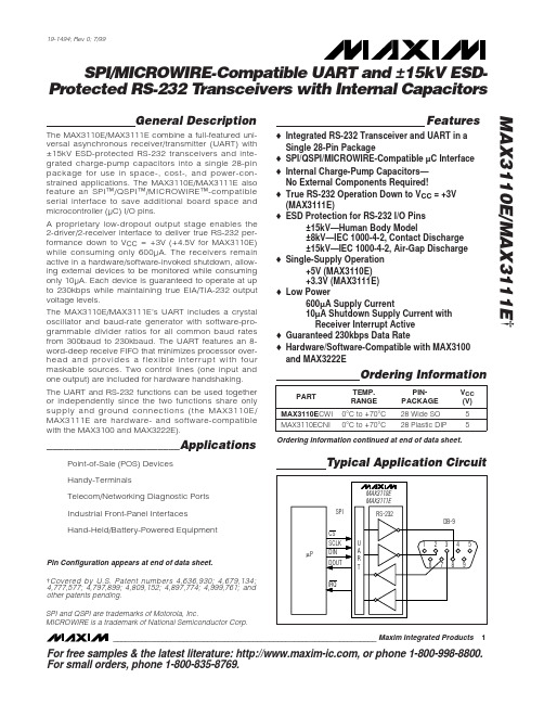
For free samples & the latest literature: , or phone 1-800-998-8800.For small orders, phone 1-800-835-8769.General DescriptionThe MAX3110E/MAX3111E combine a full-featured uni-versal asynchronous receiver/transmitter (UART) with ±15kV ESD-protected RS-232 transceivers and inte-grated charge-pump capacitors into a single 28-pin package for use in space-, cost-, and power-con-strained applications. The MAX3110E/MAX3111E also feature an SPI™/QSPI™/MICROWIRE™-compatible serial interface to save additional board space and microcontroller (µC) I/O pins.A proprietary low-dropout output stage enables the 2-driver/2-receiver interface to deliver true RS-232 per-formance down to V CC = +3V (+4.5V for MAX3110E)while consuming only 600µA. The receivers remain active in a hardware/software-invoked shutdown, allow-ing external devices to be monitored while consuming only 10µA. Each device is guaranteed to operate at up to 230kbps while maintaining true EIA/TIA-232 output voltage levels.The MAX3110E/MAX3111E’s UART includes a crystal oscillator and baud-rate generator with software-pro-grammable divider ratios for all common baud rates from 300baud to 230kbaud. The UART features an 8-word-deep receive FIFO that minimizes processor over-head and provides a flexible interrupt with four maskable sources. Two control lines (one input and one output) are included for hardware handshaking.The UART and RS-232 functions can be used together or independently since the two functions share only supply and ground connections (the MAX3110E/MAX3111E are hardware- and software-compatible with the MAX3100 and MAX3222E).________________________ApplicationsPoint-of-Sale (POS) Devices Handy-TerminalsTelecom/Networking Diagnostic Ports Industrial Front-Panel Interfaces Hand-Held/Battery-Powered EquipmentFeatureso Integrated RS-232 Transceiver and UART in a Single 28-Pin Packageo SPI/QSPI/MICROWIRE-Compatible µC Interface o Internal Charge-Pump Capacitors—No External Components Required!o True RS-232 Operation Down to V CC = +3V (MAX3111E)o ESD Protection for RS-232 I/O Pins±15kV—Human Body Model±8kV—IEC 1000-4-2, Contact Discharge ±15kV—IEC 1000-4-2, Air-Gap Dischargeo Single-Supply Operation+5V (MAX3110E)+3.3V (MAX3111E)o Low Power600µA Supply Current10µA Shutdown Supply Current with Receiver Interrupt Activeo Guaranteed 230kbps Data Rateo Hardware/Software-Compatible with MAX3100and MAX3222EMAX3110E/MAX3111E †SPI/MICROWIRE-Compatible UART and ±15kV ESD-Protected RS-232 T ransceivers with Internal Capacitors________________________________________________________________Maxim Integrated Products 119-1494; Rev 0; 7/99Typical Application CircuitOrdering InformationSPI and QSPI are trademarks of Motorola, Inc.MICROWIRE is a trademark of National Semiconductor Corp.Ordering Information continued at end of data sheet.Pin Configuration appears at end of data sheet.†Covered by U.S. Patent numbers 4,636,930; 4,679,134;4,777,577; 4,797,899; 4,809,152; 4,897,774; 4,999,761; and other patents pending.M A X 3110E /M A X 3111ESPI/MICROWIRE-Compatible UART and ±15kV ESD-Protected RS-232 T ransceivers with Internal Capacitors2_______________________________________________________________________________________ABSOLUTE MAXIMUM RATINGSELECTRICAL CHARACTERISTICS—MAX3110E(V CC = +4.5V to +5.5V, T A = T MIN to T MAX , unless otherwise noted. Typical values are measured for baud rate set to 9600baud at V CC = +5V, T A = +25°C.) (Note 2)Stresses beyond those listed under “Absolute Maximum Ratings” may cause permanent damage to the device. These are stress ratings only, and function-al operation of the device at these or any other conditions beyond those indicated in the operational sections of the specifications is not implied. Exposure to absolute maximum rating conditions for extended periods may affect device reliability.V CC to GND (MAX3110E)........................................-0.3V to +6V V CC to GND (MAX3111E).........................................-0.3V to +4V V+ to GND (Note 1)..................................................-0.3V to +7V V- to GND (Note 1)...................................................+0.3V to -7V V+ to V- (Note 1)..................................................................+13V Input Voltages to GNDCS , X1, CTS , RX, DIN, SCLK..................-0.3V to (V CC + 0.3V)T_IN, SHDN ...........................................................-0.3V to +6V R_IN..................................................................................±25V Output Voltage to GNDDOUT, RTS , TX, X2 .................................-0.3V to (V CC + 0.3V)IRQ .......................................................................-0.3V to +6V T_OUT ...........................................................................±13.2V R_OUT.....................................................-0.3V to (V CC + 0.3V)TX, RTS Output Current....................................................100mA Short-Circuit DurationX2, DOUT, IRQ (to V CC or GND).............................Continuous T_OUT (to GND) .....................................................Continuous Continuous Power Dissipation (T A = +70°C)28-pin Wide SO (derate 12.5mW/°C above +70°C) ...........1W 28-pin Plastic DIP (derate 14.3mW/°C above +70°C)....1.14W Operating Temperature RangesMAX311_EC_ _ ..................................................0°C to +70°C MAX311_EE_ _ ................................................-40°C to +85°C Storage Temperature Range ............................-65°C to +150°C Lead Temperature (soldering, 10sec).............................+300°CNote 1:V+ and V- can have maximum magnitudes of 7V, but their absolute difference should not exceed 13V.MAX3110E/MAX3111ESPI/MICROWIRE-Compatible UART and ±15kV ESD-Protected RS-232 T ransceivers with Internal Capacitors_______________________________________________________________________________________3ELECTRICAL CHARACTERISTICS—MAX3110E (continued)(V CC = +4.5V to +5.5V, T A = T MIN to T MAX , unless otherwise noted. Typical values are measured for baud rate set to 9600baud at V CC = +5V, T A = +25°C.) (Note 2)M A X 3110E /M A X 3111ESPI/MICROWIRE-Compatible UART and ±15kV ESD-Protected RS-232 T ransceivers with Internal Capacitors4_______________________________________________________________________________________ELECTRICAL CHARACTERISTICS—MAX3110E (continued)(V CC = +4.5V to +5.5V, T A = T MIN to T MAX , unless otherwise noted. Typical values are measured for baud rate set to 9600baud at V CC = +5V, T A = +25°C.) (Note 2)SPI/MICROWIRE-Compatible UART and ±15kV ESD-Protected RS-232 T ransceivers with Internal Capacitors_______________________________________________________________________________________5MAX3110E/MAX3111EELECTRICAL CHARACTERISTICS—MAX3111E(V CC= +3.0V to +3.6V, V A = T MIN to T MAX, unless otherwise noted. Typical values are measured for baud rate set to 9600baud at V CC= +3.3V, T A= +25°C.) (Note 2)M A X 3110E /M A X 3111ESPI/MICROWIRE-Compatible UART and ±15kV ESD-Protected RS-232 T ransceivers with Internal Capacitors6_______________________________________________________________________________________ELECTRICAL CHARACTERISTICS—MAX3111E (continued)(V CC = +3.0V to +3.6V, V A = T MIN to T MAX , unless otherwise noted. Typical values are measured for baud rate set to 9600baud at V CC = +3.3V, T A = +25°C.) (Note 2)MAX3110E/MAX3111E SPI/MICROWIRE-Compatible UART and ±15kV ESD-Protected RS-232 T ransceivers with Internal Capacitors _______________________________________________________________________________________7 ELECTRICAL CHARACTERISTICS—MAX3111E (continued)(V CC= +3.0V to +3.6V, V A = T MIN to T MAX, unless otherwise noted. Typical values are measured for baud rate set to 9600baud atV CC= +3.3V, T= +25°C.) (Note 2)Note 2:All currents into the device are positive; all currents out of the device are negative. All voltages are referred to device ground unless otherwise noted.Note 3:I CCSHDN(H)represents a hardware-only shutdown. In hardware shutdown, the UART is in normal operation and the charge pumps for the RS-232 transmitters are shut down.Note 4:I CCSHDN(H+S)represents a simultaneous software and hardware shutdown in which the UART and charge pumps are shut down.Note 5:Transmitter skew is measured at the transmitter zero cross points.M A X 3110E /M A X 3111ESPI/MICROWIRE-Compatible UART and ±15kV ESD-Protected RS-232 T ransceivers with Internal Capacitors8_______________________________________________________________________________________010515303540252050010002000300040005000RS-232 TRANSCEIVER SUPPLY CURRENTvs. LOAD CAPACITANCELOAD CAPACITANCE (pF)S U P P L Y C U R R E N T (m A )45042612141081610002000300040005000RS-232 TRANSMITTER SLEW RATEvs. LOAD CAPACITANCELOAD CAPACITANCE (pF)S L E W R A T E (V /µs )-10.0-5.0-7.5-2.55.07.52.5010.0010002000300040005000RS-232 TRANSMITTER OUTPUT VOLTAGEvs. LOAD CAPACITANCELOAD CAPACITANCE (pF)T R A N S M I T T E R O U T P U T V O L T A G E (V )Typical Operating Characteristics(TA = +25°C, unless otherwise noted.)10009000-40-204060100UART SUPPLY CURRENT vs. TEMPERATURE200100800700TEMPERATURE (°C)S U P P L Y C U R R E N T (µA )020806005004003001090-40-204060100UART SHUTDOWN CURRENTvs. TEMPERATURE2187TEMPERATURE (°C)S H U T D O W N C U R R E N T (µA )208065434005010010k 1000100k1MUART SUPPLY CURRENTvs. BAUD RATE150100BAUD RATE (bps)S U P P L Y C U R R E N T (µA )20025035030070060001345UART SUPPLY CURRENT vs. EXTERNAL CLOCK FREQUENCY100500EXTERNAL CLOCK FREQUENCY (MHz)S U P P L Y C U R R E N T (µA )24003002007000.20.10.60.70.8 1.0MAX3111ETX, RTS, DOUT OUTPUT CURRENT vs. OUTPUT LOW VOLTAGE (V CC = +3.3V)10VOLTAGE (V)O U T P U T S I N K C U R R E N T (m A )0.30.50.40.960504030209080000.20.10.60.70.8 1.0MAX3110ETX, RTS, DOUT OUTPUT CURRENT vs. OUTPUT LOW VOLTAGE (V CC = +5V)1070VOLTAGE (V)O U T P U T S I N K C U R R E N T (m A )0.30.50.40.96050403020MAX3110E/MAX3111ESPI/MICROWIRE-Compatible UART and ±15kV ESD-Protected RS-232 T ransceivers with Internal Capacitors_______________________________________________________________________________________9Pin DescriptionM A X 3110E /M A X 3111ESPI/MICROWIRE-Compatible UART and ±15kV ESD-Protected RS-232 T ransceivers with Internal Capacitors10______________________________________________________________________________________Detailed DescriptionThe MAX3110E/MAX3111E contain an SPI/QSPI/MICROWIRE-compatible UART and an RS-232 transceiver with two drivers and two receivers. The UART is compatible with SPI and QSPI for CPOL = 0 and CPHA = 0. The UART supports data rates up to 230kbaud for standard UART bit streams as well as IrDA and includes an 8-word receive FIFO. Also included is a 9-bit-address recogni-tion interrupt.The RS-232 transceiver has electrostatic discharge (ESD) protection on the transmitter outputs and the receiver inputs. The internal charge-pump capacitors minimize the number of external components required.The RS-232 transceivers meet EIA/TIA-232 specifica-tions for V CC down to the minimum supply voltage and are guaranteed to operate for data rates up to 250kbps. The UART and RS-232 functions operate as one device or independently since the two functions share only supply and ground connections.UARTThe universal asynchronous receiver transmitter (UART) interfaces the SPI/QSPI/MICROWIRE-compati-ble synchronous serial data from a microprocessor (µP)to asynchronous, serial-data communication ports (RS-232, IrDA). Figure 1 shows the MAX3110E/MAX3111E functional diagram. Included in the UART function is an SPI/QSPI/MICROWIRE interface, a baud-rate generator,and an interrupt generator.Figure 1. MAX3110E/MAX3111E Functional DiagramMAX3110E/MAX3111EProtected RS-232 T ransceivers with Internal CapacitorsSPI InterfaceThe MAX3110E/MAX3111E are compatible with SPI,QSPI (CPOL = 0, CPHA = 0), and MICROWIRE serial-interface standards (Figure 2). The MAX3110E/MAX3111E have a unique full-duplex-only architecture that expects a 16-bit word for DIN and simultaneously produces a 16-bit word for DOUT regardless of which read/write register is used. The DIN stream is moni-tored for its first two bits to tell the UART the type of data transfer being executed (see the Write Configuration Register , Read Configuration Register ,Write Data Register , and Read Data Registe r sections).DIN (MOSI) is latched on SCLK’s rising edge. DOUT (MISO) should be read into the µP on SCLK’s rising edge. The first bit (bit 15) of DOUT transitions on CS ’s falling edge, and bits 14–0 transition on SCLK’s fallingedge. Figure 3 shows the detailed serial timing specifi-cations for the synchronous SPI port.Only 16-bit words are expected. If CS goes high in the middle of a transmission (any time before the 16th bit),the sequence is aborted (i.e., data does not get written to individual registers). Most operations, such as the clearing of internal registers, are executed only on CS ’s rising edge. Every time CS goes low, a new 16-bit stream is expected. An example of using the Write Configuration Register is shown in Figure 4.Table 1 describes the bits located in the Write Config-uration, Read Configuration, Write Data, and Read Data Registers. This table also describes whether the bit is a read or a write bit and the power-on reset state (POR) of the bits. Figure 5 shows an example of parity and word-length control.CS SCLKSCLKSCLKSCLK(CPOL = 0, CPHA = 0)(CPOL = 0, CPHA = 1)(CPOL = 1, CPHA = 0)(CPOL = 1, CPHA = 1)COMPATIBLEWITH MAX3110E/MAX3111ENOT COMPATIBLEWITH MAX3110E/MAX3111EDIN MSB 1314121110987654321LSB DOUT MSB1314121110987654321LSBFigure 2. Compatible CPOL and CPHA Timing ModesFigure 3. Detailed Serial Timing Specifications for the Synchronous SPI PortM A X 3110E /M A X 3111EProtected RS-232 T ransceivers with Internal CapacitorsFigure 4. Write Configuration Register ExampleFigure 5. Parity and Word-Length ControlMAX3110E/MAX3111EProtected RS-232 T ransceivers with Internal CapacitorsM A X 3110E /M A X 3111EProtected RS-232 T ransceivers with Internal CapacitorsNotice to High-Level Programmers:The UART follows the SPI convention of providing a bidirectional data path for writes and reads. Whenever the data is written, data is also read back. This speeds operation over the SPI bus, and the UART needs this speed advantage when operating at high baud rates. In most high-level lan-guages, such as C, there are commands for writing and reading stream I/O devices such as the console or serial port. In C specifically, there is a “PUTCHAR” command that transmits a character and a “GETCHAR” command that receives a character. If programmers were to write direct write and read commands in C with no underlying driver code, they would notice that a PUTCHAR com-mand is really a PUTGETCHAR command. These C commands assume some form of BIOS-level support for these commands. The proper way to implement these commands is to write driver code, usually in the form of an assembly-language interrupt-service routine and a callable routine used by high-level routines. This driverhandles the interrupts and manages the receive and transmit buffers for the MAX3110E/MAX3111E. When a PUTCHAR executes, this driver is called and it safely buffers any characters received when the current character is transmitted. When a GETCHAR executes, it checks its own receive buffer before getting data from the UART. See the C-language Outline of a MAX3110E/MAX3111E Software Driver in Listing 1, which appears at the end of this data sheet.Listing 1 is a C-language outline of an interrupt-driven software driver that interfaces to a MAX3110E/MAX3111E, providing an intermediate layer between the bit-manipulation subroutine and the familiar PUTCHAR/GETCHAR subroutines.The user must supply code for managing the transmit and receive queues as well as the low-level hardware interface itself. The interrupt control hardware must be initialized before this driver is called.Table 1. Bit Descriptions (continued)Protected RS-232 T ransceivers with Internal CapacitorsWrite Configuration Register (D15, D14 = 1, 1) Configure the UART by writing a 16-bit word to the write configuration register, which programs the baud rate, data word length, parity enable, and enable of the 8-word receive FIFO. In this mode, bits 15 and 14 of the DIN configuration word are both required to be 1 in order to enable the write configuration mode. Bits 13–0 of the DIN configuration word set the configuration of the UART. Table 2 shows the bit assignment for the write configuration register. The write configuration reg-ister allows selection between normal UART timing and IrDA timing, provides shutdown control, and contains four interrupt mask bits.Using the write configuration register clears the receive FIFO and the R, T, RA/FE, D0r–D7r, D0t–D7t, Pr, and Pt registers. RTS and CTS remain unchanged. The new configuration is valid on CS’s rising edge if the transmit buffer is empty (T = 1) and transmission is over. If the latest transmission has not been completed (T = 0), the registers are updated when the transmission is over. The write configuration register bits (FEN, SHDNi, IR, ST, PE, L, B3–B0) take effect after the current transmis-sion is over. The mask bits (TM, RM, PM, RAM) take effect immediately after SCLK’s 16th rising edge.Bits 15 and 14 of the DOUT write configuration (R and T) are sent out of the MAX3110E/MAX3111E along with 14 trailing zeros. The use of the R and T bits is optional, but ignore the 14 trailing zeros.Warning!The UART requires stable crystal oscillator operation before configuration (typically ~25ms after power-up). Upon power-up, compare the write configu-ration bits with the read configuration bits in a software loop until both match. This ensures that the oscillator is stable and that the UART is configured correctly.Read Configuration Mode (D15, D14 = 0, 1) The read configuration mode is used to read back the last configuration written to the UART. In this mode, bits 15 and 14 of the DIN configuration word are required to be 0 and 1, respectively, to enable the read configura-tion mode. Bits 13–1 of the DIN word should be zeros,and bit 0 is the test bit to put the UART in test mode(see the Test Mode section). Table 3 shows the bit assignment for the read configuration register.Test ModeThe device enters a test mode if bit 0 of the DIN config-uration word equals one when doing a read configura-tion. In this mode, if CS= 0, the RTS pin transmits aclock that is 16-times the baud rate. The TX pin is lowas long as CS remains low while in test mode. Table 3 shows the bit assignment for the read configuration register.Write Data Register (D15, D14 = 1, 0)Use the write data register for transmitting to the TX-buffer and receiving from the RX buffer (and RX FIFOwhen enabled). When using this register, the DIN and DOUT write data words are used simultaneously, andbits 13–11 for both the DIN and DOUT write data wordsare meaningless zeros. The DIN write data word con-tains the data that is being transmitted, and the DOUTwrite data word contains the data that is being receivedfrom the RX FIFO. Table 4 shows the bit assignment forthe write data mode. To change the RTS pin’s outputstate without transmitting data, set the TE bit high. If performing a write data operation, the R bit will clear onthe falling edge of SCLK’s 16th clock pulse if no newdata is available.Read Data Register (D15, D14 = 0, 0)Use the read data register for receiving data from theRX FIFO. When using this register, bits 15 and 14 ofDIN are both required to be 0. Bits 13–0 of the DINread-data word should be zeros. Table 5 shows the bit assignments for the read data mode. Reading dataclears the R bit and interrupt IRQ. If performing a readdata operation, the R bit will clear on the falling edge of SCLKs 16th clock pulse if no new data is available.MAX3110E/MAX3111EM A X 3110E /M A X 3111EProtected RS-232 T ransceivers with Internal CapacitorsTable 2. Write Configuration (D15, D14 = 1, 1)Notes:bit 15: DOUTR = 1, Data is available to be read or is being read from the receive register or FIFO.R = 0, Receive register and FIFO are empty.bit 14: DOUTT = 1, Transmit buffer is empty.T = 0, Transmit buffer is full.bits 13–0: DOUT Zerosbits 15, 14: DIN1,1 = Write Configuration bit 13: DINFEN = 0, FIFO is enabled.FEN = 1, FIFO is disabled.bit 12: DINSHDNi = 1, Enter software shutdown.SHDNi = 0, Exit software shutdown.bit 11: DINTM = 1, Transmit buffer empty interrupt is enabled.TM = 0, Transmit buffer empty interrupt is disabled.bit 10: DINRM = 1, Data available in the receive register or FIFO interrupt is enabled.RM = 0, Data available in the receive register or FIFO interrupt is disabled.bit 9: DINPM = 1, Parity bit high received interrupt is enabled.PM = 0, Parity bit received interrupt is disabled.bit 8: DINRAM = 1, Receiver-activity (shutdown mode)/Framing-error (normal operation) interrupt is enabled.RAM = 0, Receiver-activity (shutdown mode)/Framing-error (normal operation) interrupt is disabled.bit 7: DINIR = 1, IrDA mode is enabled.IR = 0, IrDA mode is disabled.bit 6: DINST = 1, Transmit two stop-bits.ST = 0, Transmit one stop-bit.bit 5: DINPE = 1, Parity is enabled for both transmit (state of Pt) and receive.PE = 0, Parity is disabled for both transmit and receive.bit 4: DINL = 1, 7-bit words (8-bit words if PE = 1)L = 0, 8-bit words (9-bit words if PE = 1)bits 3–0: DINB3–B0 = XXXX, Baud-Rate Divisor Select Bits (see Table 6)D15 is present at DOUT on CS ’s falling edge. Consecutive bits are clocked out on SCLK’s falling edge.MAX3110E/MAX3111EProtected RS-232 T ransceivers with Internal CapacitorsTable 3. Read Configuration (D15, D14 = 0, 1)Notes:bit 15: DOUTR = 1, Data is available to be read or is being read from the receive register or FIFO.R = 0, Receive register and FIFO are empty.bit 14: DOUTT = 1, Transmit buffer is empty.T = 0, Transmit buffer is full.bit 13: DOUTFEN = 0, FIFO is enabled.FEN = 1, FIFO is disabled.bit 12: DOUTSHDNo = 1, Software shutdown is enabled.SHDNo = 0, Software shutdown is disabled.bit 11: DOUTTM = 1, Transmit buffer empty interrupt is enabled.TM = 0, Transmit buffer empty interrupt is disabled.bit 10: DOUTRM = 1, Data available in the receive register or FIFO interrupt is enabled.RM = 0, Data available in the receive register or FIFO interrupt is disabled.bit 9: DOUTPM = 1, Parity bit high received interrupt is enabled.PM = 0, Parity bit received interrupt is disabled.bit 8: DOUTRAM = 1, Receiver-activity (shutdown mode)/Framing-error (normal operation) interrupt is enabled.RAM = 0, Receiver-activity (shutdown mode)/Framing-error (normal operation) interrupt is disabled.bit 7: DOUTIR = 1, IrDA mode is enabled.IR = 0, IrDA mode is disabled.bit 6: DOUTST = 1, Transmit two stop-bits.ST = 0, Transmit one stop-bit.bit 5: DOUTPE = 1, Parity is enabled for both transmit (state of Pt) and receive.PE = 0, Parity is disabled for both transmit and receive.bit 4: DOUTL = 1, 7-bit words (8-bit words if PE = 1)L = 0, 8-bit words (9-bit words if PE = 1)bits 3–0: DOUTB3–B0 = XXXX Baud-Rate Divisor Select Bits (see Table 6)bit 15, 14: DIN0,1 = Read Configuration bits 13–1: DIN Zerosbit 0: DINIf TEST = 1 and CS = 0, then RTS =16xBaudCLK TEST = 0, Disables test modeD15 is present at DOUT on CS ’s falling edge. Consecutive bits are clocked out on SCLK’s falling edge.M A X 3110E /M A X 3111EProtected RS-232 T ransceivers with Internal CapacitorsTable 4. Write Data (D15, D14 = 1, 0)Notes:bit 15: DOUTR = 1, Data is available to be read or is being read from the receive register or FIFO.R = 0, Receive register and FIFO are empty.bit 14: DOUTT = 1, Transmit buffer is empty.T = 0, Transmit buffer is full.bits 13–11: DOUT Zeros bit 10: DOUTRA/FE = Receive-Activity (Uart shutdown)/Framing-Error (Normal Operation) bit bit 9: DOUTCTS = CTS input state. If CTS = 0, then CTS = 1 and vice versa.bit 8: DOUTPr = Received Parity Bit. This is only valid if PE = 1. bits 7–0: DOUTD7t–D0t = Received Data Bits. D7r = 0 for L = 1.bits 15, 14: DIN 1, 0 = Write Data bits 13–11: DIN Zeros bit 10: DINTE = 1, Disables transmit and only RTS will be updated.TE = 0, Enables transmit.bit 9: DINRTS = 1, Configures RTS = 0 (logic low).RTS = 0, Configures RTS = 1 (logic high).bit 8: DINPt = 1, Transmit parity bit is high. If PE = 1, a high parity bit will be transmitted. If PE = 0, then no parity bit will be transmitted.Pt = 0, Transmit parity bit is low. If PE = 1, a low parity bit will be transmitted. If PE = 0, then no parity bit will be transmitted.bits 7–0: DIND7t–D0t = Transmitting Data Bits. D7t is ignored when L = 1.D15 is present at DOUT on CS ’s falling edge. Consecutive bits are clocked out on SCLK’s falling edge.MAX3110E/MAX3111EProtected RS-232 T ransceivers with Internal CapacitorsTable 5. Read Data (D15, D14 = 0, 0)Notes:bits 15: DOUTR = 1, Data is available to be read or is being read from the receive register or FIFO.R = 0, Receive register and FIFO are empty.bit 14: DOUTT = 1, Transmit buffer is empty.T = 0, Transmit buffer is full.bits 13–11: DOUT Zeros bit 10: DOUTRA/FE = Receive-Activity (UART shutdown)/Framing-Error (Normal Operation) Bit bit 9: DOUTCTS = CTS input state. If CTS = 0, then CTS = 1 and vice versa.bit 8: DOUTPr = Received parity bit. This is only valid if PE = 1. bits 7–0: DOUTD7t–D0t = Received Data Bits. D7r = 0 for L = 1.bits 15, 14: DIN 0, 0 = Read Data bits 13–0: DIN ZerosD15 is present at DOUT on CS ’s falling edge. Consecutive bits are clocked out on SCLK’s falling edge.M A X 3110E /M A X 3111EProtected RS-232 T ransceivers with Internal CapacitorsBaud-Rate GeneratorThe baud-rate generator determines the rate at which the transmitter and receiver operate. Bits B3–B0 in the write configuration register determine the baud-rate divisor (BRD), which divides the X1 oscillator frequen-cy. The on-board oscillator operates with either a 1.8432MHz or a 3.6864MHz crystal or is driven at X1with a 45% to 55% duty-cycle square wave. Table 6shows baud-rate divisors for given input codes as well as the baud rate for 1.8432MHz and 3.684MHz crystals.The generator’s clock is 16-times the baud rate.Interrupt Sources and MasksUsing the Read Data or Write Data register clears the interrupt IRQ,assuming the conditions that initiated the interrupt no longer exist. Table 7 gives the details for each interrupt source. Figure 6 shows the functional diagram for the interrupt sources and mask blocks.Following are two examples of setting up an IRQ for the MAX3110E/MAX3111E:Example 1.Set up only the transmit buffer-empty inter-rupt. Send the 16-bit word below into DIN of the MAX3110E/MAX3111E using the Write Configuration register. This 16-bit word configures the MAX3110E/MAX3111E for 9600bps, 8-bit words, no parity, and one stop bit with a 1.8432MHz crystal.binary 1100100000001010HEX C80AExample 2.Set up only the data-available (or data-being-read) interrupt.Send the 16-bit word below into DIN of the MAX3110E/MAX3111E using the Write Configuration register. This 16-bit word configures the MAX3110E/MAX3111E for 9600bps, 8-bit words, no parity, and one stop bit with a 1.8432MHz crystal.binary 1100010000001010HEX C40AReceive FIFOThe MAX3110E/MAX3111E contain an 8-word receive FIFO for data received by the UART to minimize processor overhead. Using the UART-software shut-down clears the receive FIFO. Upon power-up, the receive FIFO is enabled. To disable the receive FIFO,set the FEN bit high when writing to the Write Configuration register. To check whether the FIFO is enabled or disabled, read back the FEN bit using the Read Configuration.Figure 6. Functional Diagram for Interrupt Sources and Mask Blocks*Standard baud rates shown in bold **Default baud rate。

General Description The MAX3483, MAX3485, MAX3486, MAX3488,MAX3490, and MAX3491 are 3.3V , low-power transceivers forRS-485 and RS-422 communication. Each part containsone driver and one receiver. The MAX3483 and MAX3488feature slew-rate-limited drivers that minimize EMI andreduce reflections caused by improperly terminatedcables, allowing error-free data transmission at data ratesup to 250kbps. The partially slew-rate-limited MAX3486transmits up to 2.5Mbps. The MAX3485, MAX3490, andMAX3491 transmit at up to 10Mbps.Drivers are short-circuit current-limited and are protectedagainst excessive power dissipation by thermal shutdowncircuitry that places the driver outputs into a high-imped-ance state. The receiver input has a fail-safe feature thatguarantees a logic-high output if both inputs are opencircuit.The MAX3488, MAX3490, and MAX3491 feature full-duplex communication, while the MAX3483, MAX3485, andMAX3486 are designed for half-duplex communication.Applications ●Low-Power RS-485/RS-422 Transceivers ●Telecommunications ●Transceivers for EMI-Sensitive Applications ●Industrial-Control Local Area NetworksFeatures●Operate from a Single 3.3V Supply—No Charge Pump!●Interoperable with +5V Logic ●8ns Max Skew (MAX3485/MAX3490/MAX3491)●Slew-Rate Limited for Errorless Data Transmission (MAX3483/MAX3488)●2nA Low-Current Shutdown Mode (MAX3483/MAX3485/MAX3486/MAX3491)●-7V to +12V Common-Mode Input Voltage Range ●Allows up to 32 Transceivers on the Bus ●Full-Duplex and Half-Duplex Versions Available ●Industry Standard 75176 Pinout (MAX3483/MAX3485/MAX3486)●Current-Limiting and Thermal Shutdown for Driver Overload Protection 19-0333; Rev 1; 5/19Ordering Information continued at end of data sheet.*Contact factory for for dice specifications.PARTTEMP . RANGE PIN-PACKAGE MAX3483CPA0°C to +70°C 8 Plastic DIP MAX3483CSA0°C to +70°C 8 SO MAX3483C/D0°C to +70°C Dice*MAX3483EPA-40°C to +85°C 8 Plastic DIP MAX3483ESA-40°C to +85°C 8 SO MAX3485CPA0°C to +70°C 8 Plastic DIP MAX3485CSA0°C to +70°C 8 SO MAX3485C/D0°C to +70°C Dice*MAX3485EPA-40°C to +85°C 8 Plastic DIP MAX3485ESA -40°C to +85°C 8 SO PARTNUMBERGUARANTEED DATA RATE (Mbps)SUPPLY VOLTAGE (V)HALF/FULL DUPLEX SLEW-RATE LIMITED DRIVER/RECEIVER ENABLE SHUTDOWN CURRENT (nA)PIN COUNT MAX34830.25 3.0 to 3.6Half Yes Yes 28MAX348510Half No No 28MAX34862.5Half Yes Yes 28MAX34880.25Half Yes Yes —8MAX349010Half No No —8MAX349110Half No Yes 214MAX3483/MAX3485/MAX3486/MAX3488/MAX3490/MAX3491Selection TableOrdering Information找电子元器件上宇航军工Figure 1. MAX3483/MAX3485/MAX3486 Pin Configuration and Typical Operating Circuit Figure 2. MAX3488/MAX3490 Pin Configuration and Typical Operating Circuit Figure 3. MAX3491 Pin Configuration and Typical Operating CircuitMAX3486/MAX3488/MAX3490/MAX3491True RS-485/RS-422 TransceiversFigure 22. MAX3488/MAX3490/MAX3491 Full-Duplex RS-485 NetworkFigure 23. Line Repeater for MAX3488/MAX3490/MAX3491MAX3486/MAX3488/MAX3490/MAX3491True RS-485/RS-422 Transceivers。


The Model 3120-ASX is Pacific’s latest addition to its line of Manual and Programmable AC Power Sources. Power Conversion within the ASX Series is achieved by high frequency pulse width modulation, resulting in cool, quiet and efficient operation.The 3120-ASX is ideal for AC test, frequency conversion, laboratory and bench-power applications.AC TEST POWERThe 3120ASX is equipped with the UPC Programmable Controller, a powerful micro-controller used to create a fully integrated test system. It supplies a variety of power conditions to the device under test and meters/analyzes all output performance parameters.FREQUENCY/VOLTAGE CONVERSIONThe 3120-ASX is an excellent source of stable AC V oltage over the frequency range of 15 to 1,200Hz. The output frequency is quartz-crystal stabilized. Output voltages up to 600V are available.PHASE CONVERSIONWith the ability to provide single and three-phase outputs, the3120ASX is the perfect choice to provide three-phase input to split (two-phase) or single-phase output power conversion.UPC SERIES CONTROLLERThe latest additions to Pacific’s family of UPC Controllers are the UPC-3M and UPC-3. The UPC Controller is a modular component of the ASX Series and is available in either Manual or Programmable Configurations.All UPC Controllers include precise metering functions with data displayed via a 160-character LCD display.This, along with the 30-key front panel, provides the industry’s most powerful and user-friendly controller.The UPC-3 is available with either RS-232 or GPIB remote interface. Commands are structured in accordance with SCPI (Standard Commands for Programmable Instruments). The RS-232 serial port operates up to 38.4kBps. The GPIB interface is compatible with the IEEE-488.2.Standard FEATURES of each system include:• 22 Waveform Library – Arbitrary Waveform Generator• 15 to 1,200Hz Operation – 5,000 Hz Small Signal Bandwidth • Precision V oltage Programming – 0.05% with Continuous Self-Calibration (CSC) engaged• Precision True-RMS metering of volts, amps, and power for displays and reporting • RS-232 interface with SCPI• 1 phase/3 phase Switch Selectable Output from front panel or bus command• 99 steady state programs with associated transients for static and dynamic test applicationsAvailable Options with each system include:GPIB (IEEE-488.2) Interface with SCPI • Programmable Output Impedance• Harmonic Analysis (FFT) and Waveform Synthesis • Peak Inrush Capture and Waveform Analysis • LabVIEW for Windows • ™ and LabWindows ™Instrument DriversUPC Manager Software Suite• Wide range of Output Magnetics for worldwide testing• +1 800-854-2433Tel: +1 949-251-1800 Fax: +1 949-756-0756Model 3120-ASX12kVA – High Performance AC Power SourceIrvine, California, USA 92614+1 800-854-2433T el: +1 949-251-1800Fax: +1 949-756-0756MODEL RATEDPOWER(V A)OUTPUTFORM(Note 2)OUTPUTVOLTSMAX(Note 3)V rmsOUTPUTAMPSMAX(Note 6)(A rms)OUTPUTAMPS(Note 4)(A Pk)OUTPUTMAGNETICSINPUTPOWERFORMPANELHEIGHT WEIGHT(LBS.)3120-ASX12,0001Ø13596300EXT.3Ø15¾"-9U40cm215 Lbs.97.5Kg. 1Ø(SPLIT)270481503Ø13532100MODEL 3120ASX-UPC3 SUMMARY TABLENOTES:1. Rated output power is based on a combination of output voltage, current and load power factor. Values stated represent the maximum capabilities of a given model.Consult factory for assistance in determining specific unit capabilities as they might apply to your application.2. Unit is operable as single phase with dual voltage range capability or as a three phase. Output voltage ranges and 1Ø/3Ø conversions are selected by front panel or bus commands.3. Output voltage range is for standard unit. Vmax is output voltage with nominal input and full rated load applied. Other voltage ranges are available with the output magnetics option.4. Peak repetitive pulse current for non-linear loads. Consult factory for overload ratings.5. Three phase input with in-rush limiting: 208, 220, 230, 240, 380, 400, 416, and 480 V AC ± 10%.6. Available current will vary with output voltage and power factor.Power Source SpecificationsOUTPUT FREQUENCY: 15 to 1,200Hz Full PowerLINE REGULATION: 0.1% Max For ±10% line changeLOAD REGULATION: 0.25% 15 to 400Hz0.50% 400 to 1,200HzWith external sense enabledImproves to less than 0.1% withContinuous Self-Calibration enabledOUTPUT DISTORTION: 0.25% THDA VG 15 to 200Hz0.50% THDA VG200 to 1,200Hz RIPPLE AND NOISE: -66dBRESPONSE TIME: 60 microseconds typical, 10-90%load step.Mechanical SpecificationsThe 3120-ASX is designed for operation in 19" equipment racks. Model is equipped with retractable handles for ease of transportation. MOUNTING: Standard 19" rackHEIGHT: 9U - 15.75" - 40cmDEPTH: Approximately 24" (61cm), from front panel to therear of the chassis.COOLING: Front or side forced-air intake with rear exhaust.Automatic Fan Speed Control for low acousticnoise and extended fan life.KEY FEATURES UPC SERIES CONTROLLERPROGRAMMABLE Dynamic output impedance (ZO ) is programmableOUTPUT Range varies with model, but usually results in a IMPEDANCE: ±10% change in output voltage at maximum-ratedload current. (UPC-3 Option). PROGRAMMABLE Programmable Current limit is provided on the CURRENT LIMIT: UPC-3 controllers. Programmable range is from0 to I peak, MAX of the power source.WA VEFORM The UPC-3 controller contains a waveform library LIBRARY: that stores 22 executable waveforms in Non-volatileRAM. Waveforms 2-16 are editable via the frontpanel or bus command.WA VEFORM Provides waveform creation by entering the SYNTHESIS: magnitude (% fund.) and phase angle for the 2ndthrough 51st harmonic (UPC-3 option).W A VEFORM Reports voltage and current harmonic content as ANALYSIS: as a % of the fundamental and phase angle forthe 2nd through the 51st harmonic. (UPC-3 option).OUTPUT True RMS reading of each phase is measured VOLTMETER: independently. Line-to-neutral and line-to-linevoltages are displayed.OUTPUT True RMS reading of each phase. RMS and Peak AMMETER: Current, as well as Crest Factor are displayed.OUTPUT Measures True Power (kW), Apparent Power POWER: (kV A) and Power Factor.AUX. Each phase is algebraically summed with UPS INPUTS: waveform and amplified 25x to the direct coupledoutput.AM INPUTS: ±10 VDC input for each phase modulates theoutput voltage ±100%.©2009 Pacific Power SourceIrvine CA, U.S.A. Subject to change without notice#23120ASXDS0509。
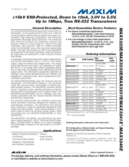


For pricing, delivery, and ordering information,please contact Maxim/Dallas Direct!at 1-888-629-4642, or visit Maxim’s website at .General DescriptionThe MAX481, MAX483, MAX485, MAX487–MAX491, and MAX1487 are low-power transceivers for RS-485 and RS-422 communication. Each part contains one driver and one receiver. The MAX483, MAX487, MAX488, and MAX489feature reduced slew-rate drivers that minimize EMI and reduce reflections caused by improperly terminated cables,thus allowing error-free data transmission up to 250kbps.The driver slew rates of the MAX481, MAX485, MAX490,MAX491, and MAX1487 are not limited, allowing them to transmit up to 2.5Mbps.These transceivers draw between 120µA and 500µA of supply current when unloaded or fully loaded with disabled drivers. Additionally, the MAX481, MAX483, and MAX487have a low-current shutdown mode in which they consume only 0.1µA. All parts operate from a single 5V supply.Drivers are short-circuit current limited and are protected against excessive power dissipation by thermal shutdown circuitry that places the driver outputs into a high-imped-ance state. The receiver input has a fail-safe feature that guarantees a logic-high output if the input is open circuit.The MAX487 and MAX1487 feature quarter-unit-load receiver input impedance, allowing up to 128 MAX487/MAX1487 transceivers on the bus. Full-duplex communi-cations are obtained using the MAX488–MAX491, while the MAX481, MAX483, MAX485, MAX487, and MAX1487are designed for half-duplex applications.________________________ApplicationsLow-Power RS-485 Transceivers Low-Power RS-422 Transceivers Level TranslatorsTransceivers for EMI-Sensitive Applications Industrial-Control Local Area Networks__Next Generation Device Features♦For Fault-Tolerant ApplicationsMAX3430: ±80V Fault-Protected, Fail-Safe, 1/4Unit Load, +3.3V, RS-485 TransceiverMAX3440E–MAX3444E: ±15kV ESD-Protected,±60V Fault-Protected, 10Mbps, Fail-Safe, RS-485/J1708 Transceivers♦For Space-Constrained ApplicationsMAX3460–MAX3464: +5V, Fail-Safe, 20Mbps,Profibus RS-485/RS-422 TransceiversMAX3362: +3.3V, High-Speed, RS-485/RS-422Transceiver in a SOT23 PackageMAX3280E–MAX3284E: ±15kV ESD-Protected,52Mbps, +3V to +5.5V, SOT23, RS-485/RS-422,True Fail-Safe ReceiversMAX3293/MAX3294/MAX3295: 20Mbps, +3.3V,SOT23, RS-855/RS-422 Transmitters ♦For Multiple Transceiver ApplicationsMAX3030E–MAX3033E: ±15kV ESD-Protected,+3.3V, Quad RS-422 Transmitters ♦For Fail-Safe ApplicationsMAX3080–MAX3089: Fail-Safe, High-Speed (10Mbps), Slew-Rate-Limited RS-485/RS-422Transceivers♦For Low-Voltage ApplicationsMAX3483E/MAX3485E/MAX3486E/MAX3488E/MAX3490E/MAX3491E: +3.3V Powered, ±15kV ESD-Protected, 12Mbps, Slew-Rate-Limited,True RS-485/RS-422 TransceiversMAX481/MAX483/MAX485/MAX487–MAX491/MAX1487Low-Power, Slew-Rate-Limited RS-485/RS-422 Transceivers______________________________________________________________Selection Table19-0122; Rev 8; 10/03Ordering Information appears at end of data sheet.M A X 481/M A X 483/M A X 485/M A X 487–M A X 491/M A X 1487Low-Power, Slew-Rate-Limited RS-485/RS-422 Transceivers 2_______________________________________________________________________________________ABSOLUTE MAXIMUM RATINGSSupply Voltage (V CC ).............................................................12V Control Input Voltage (RE , DE)...................-0.5V to (V CC + 0.5V)Driver Input Voltage (DI).............................-0.5V to (V CC + 0.5V)Driver Output Voltage (A, B)...................................-8V to +12.5V Receiver Input Voltage (A, B).................................-8V to +12.5V Receiver Output Voltage (RO).....................-0.5V to (V CC +0.5V)Continuous Power Dissipation (T A = +70°C)8-Pin Plastic DIP (derate 9.09mW/°C above +70°C)....727mW 14-Pin Plastic DIP (derate 10.00mW/°C above +70°C)..800mW 8-Pin SO (derate 5.88mW/°C above +70°C).................471mW14-Pin SO (derate 8.33mW/°C above +70°C)...............667mW 8-Pin µMAX (derate 4.1mW/°C above +70°C)..............830mW 8-Pin CERDIP (derate 8.00mW/°C above +70°C).........640mW 14-Pin CERDIP (derate 9.09mW/°C above +70°C).......727mW Operating Temperature RangesMAX4_ _C_ _/MAX1487C_ A...............................0°C to +70°C MAX4__E_ _/MAX1487E_ A.............................-40°C to +85°C MAX4__MJ_/MAX1487MJA...........................-55°C to +125°C Storage Temperature Range.............................-65°C to +160°C Lead Temperature (soldering, 10sec).............................+300°CDC ELECTRICAL CHARACTERISTICS(V CC = 5V ±5%, T A = T MIN to T MAX , unless otherwise noted.) (Notes 1, 2)Stresses beyond those listed under “Absolute Maximum Ratings” may cause permanent damage to the device. These are stress ratings only, and functional operation of the device at these or any other conditions beyond those indicated in the operational sections of the specifications is not implied. Exposure to absolute maximum rating conditions for extended periods may affect device reliability.V V IN = -7VV IN = 12V V IN = -7V V IN = 12V Input Current (A, B)I IN2V TH k Ω48-7V ≤V CM ≤12V, MAX487/MAX1487R INReceiver Input Resistance -7V ≤V CM ≤12V, all devices except MAX487/MAX1487R = 27Ω(RS-485), Figure 40.4V ≤V O ≤2.4VR = 50Ω(RS-422)I O = 4mA, V ID = -200mV I O = -4mA, V ID = 200mV V CM = 0V-7V ≤V CM ≤12V DE, DI, RE DE, DI, RE MAX487/MAX1487,DE = 0V, V CC = 0V or 5.25VDE, DI, RE R = 27Ωor 50Ω, Figure 4R = 27Ωor 50Ω, Figure 4R = 27Ωor 50Ω, Figure 4DE = 0V;V CC = 0V or 5.25V,all devices except MAX487/MAX1487CONDITIONSk Ω12µA ±1I OZRThree-State (high impedance)Output Current at ReceiverV 0.4V OL Receiver Output Low Voltage 3.5V OH Receiver Output High Voltage mV 70∆V TH Receiver Input Hysteresis V -0.20.2Receiver Differential Threshold Voltage-0.2mA 0.25mA-0.81.01.55V OD2Differential Driver Output (with load)V 2V 5V OD1Differential Driver Output (no load)µA±2I IN1Input CurrentV 0.8V IL Input Low Voltage V 2.0V IH Input High Voltage V 0.2∆V OD Change in Magnitude of Driver Common-Mode Output Voltage for Complementary Output States V 0.2∆V OD Change in Magnitude of Driver Differential Output Voltage for Complementary Output States V 3V OC Driver Common-Mode Output VoltageUNITS MINTYPMAX SYMBOL PARAMETERMAX481/MAX483/MAX485/MAX487–MAX491/MAX1487Low-Power, Slew-Rate-Limited RS-485/RS-422 Transceivers_______________________________________________________________________________________3SWITCHING CHARACTERISTICS—MAX481/MAX485, MAX490/MAX491, MAX1487(V CC = 5V ±5%, T A = T MIN to T MAX , unless otherwise noted.) (Notes 1, 2)DC ELECTRICAL CHARACTERISTICS (continued)(V CC = 5V ±5%, T A = T MIN to T MAX , unless otherwise noted.) (Notes 1, 2)ns 103060t PHLDriver Rise or Fall Time Figures 6 and 8, R DIFF = 54Ω, C L1= C L2= 100pF ns MAX490M, MAX491M MAX490C/E, MAX491C/E2090150MAX481, MAX485, MAX1487MAX490M, MAX491MMAX490C/E, MAX491C/E MAX481, MAX485, MAX1487Figures 6 and 8, R DIFF = 54Ω,C L1= C L2= 100pF MAX481 (Note 5)Figures 5 and 11, C RL = 15pF, S2 closedFigures 5 and 11, C RL = 15pF, S1 closed Figures 5 and 11, C RL = 15pF, S2 closed Figures 5 and 11, C RL = 15pF, S1 closed Figures 6 and 10, R DIFF = 54Ω,C L1= C L2= 100pFFigures 6 and 8,R DIFF = 54Ω,C L1= C L2= 100pF Figures 6 and 10,R DIFF = 54Ω,C L1= C L2= 100pF CONDITIONS ns 510t SKEW ns50200600t SHDNTime to ShutdownMbps 2.5f MAX Maximum Data Rate ns 2050t HZ Receiver Disable Time from High ns 103060t PLH 2050t LZ Receiver Disable Time from Low ns 2050t ZH Driver Input to Output Receiver Enable to Output High ns 2050t ZL Receiver Enable to Output Low 2090200ns ns 134070t HZ t SKD Driver Disable Time from High |t PLH - t PHL |DifferentialReceiver Skewns 4070t LZ Driver Disable Time from Low ns 4070t ZL Driver Enable to Output Low 31540ns51525ns 31540t R , t F 2090200Driver Output Skew to Output t PLH , t PHL Receiver Input to Output4070t ZH Driver Enable to Output High UNITS MIN TYP MAX SYMBOL PARAMETERFigures 7 and 9, C L = 100pF, S2 closed Figures 7 and 9, C L = 100pF, S1 closed Figures 7 and 9, C L = 15pF, S1 closed Figures 7 and 9, C L = 15pF, S2 closedM A X 481/M A X 483/M A X 485/M A X 487–M A X 491/M A X 1487Low-Power, Slew-Rate-Limited RS-485/RS-422 Transceivers 4_______________________________________________________________________________________SWITCHING CHARACTERISTICS—MAX483, MAX487/MAX488/MAX489(V CC = 5V ±5%, T A = T MIN to T MAX , unless otherwise noted.) (Notes 1, 2)SWITCHING CHARACTERISTICS—MAX481/MAX485, MAX490/MAX491, MAX1487 (continued)(V CC = 5V ±5%, T A = T MIN to T MAX , unless otherwise noted.) (Notes 1, 2)3001000Figures 7 and 9, C L = 100pF, S2 closed Figures 7 and 9, C L = 100pF, S1 closed Figures 5 and 11, C L = 15pF, S2 closed,A - B = 2VCONDITIONSns 40100t ZH(SHDN)Driver Enable from Shutdown toOutput High (MAX481)nsFigures 5 and 11, C L = 15pF, S1 closed,B - A = 2Vt ZL(SHDN)Receiver Enable from Shutdownto Output Low (MAX481)ns 40100t ZL(SHDN)Driver Enable from Shutdown toOutput Low (MAX481)ns 3001000t ZH(SHDN)Receiver Enable from Shutdownto Output High (MAX481)UNITS MINTYP MAX SYMBOLPARAMETERt PLH t SKEW Figures 6 and 8, R DIFF = 54Ω,C L1= C L2= 100pFt PHL Figures 6 and 8, R DIFF = 54Ω,C L1= C L2= 100pFDriver Input to Output Driver Output Skew to Output ns 100800ns ns 2000MAX483/MAX487, Figures 7 and 9,C L = 100pF, S2 closedt ZH(SHDN)Driver Enable from Shutdown to Output High2502000ns2500MAX483/MAX487, Figures 5 and 11,C L = 15pF, S1 closedt ZL(SHDN)Receiver Enable from Shutdown to Output Lowns 2500MAX483/MAX487, Figures 5 and 11,C L = 15pF, S2 closedt ZH(SHDN)Receiver Enable from Shutdown to Output Highns 2000MAX483/MAX487, Figures 7 and 9,C L = 100pF, S1 closedt ZL(SHDN)Driver Enable from Shutdown to Output Lowns 50200600MAX483/MAX487 (Note 5) t SHDN Time to Shutdownt PHL t PLH , t PHL < 50% of data period Figures 5 and 11, C RL = 15pF, S2 closed Figures 5 and 11, C RL = 15pF, S1 closed Figures 5 and 11, C RL = 15pF, S2 closed Figures 5 and 11, C RL = 15pF, S1 closed Figures 7 and 9, C L = 15pF, S2 closed Figures 6 and 10, R DIFF = 54Ω,C L1= C L2= 100pFFigures 7 and 9, C L = 15pF, S1 closed Figures 7 and 9, C L = 100pF, S1 closed Figures 7 and 9, C L = 100pF, S2 closed CONDITIONSkbps 250f MAX 2508002000Maximum Data Rate ns 2050t HZ Receiver Disable Time from High ns 25080020002050t LZ Receiver Disable Time from Low ns 2050t ZH Receiver Enable to Output High ns 2050t ZL Receiver Enable to Output Low ns ns 1003003000t HZ t SKD Driver Disable Time from High I t PLH - t PHL I DifferentialReceiver SkewFigures 6 and 10, R DIFF = 54Ω,C L1= C L2= 100pFns 3003000t LZ Driver Disable Time from Low ns 2502000t ZL Driver Enable to Output Low ns Figures 6 and 8, R DIFF = 54Ω,C L1= C L2= 100pFns 2502000t R , t F 2502000Driver Rise or Fall Time ns t PLH Receiver Input to Output2502000t ZH Driver Enable to Output High UNITS MIN TYP MAX SYMBOL PARAMETERMAX481/MAX483/MAX485/MAX487–MAX491/MAX1487Low-Power, Slew-Rate-Limited RS-485/RS-422 Transceivers_______________________________________________________________________________________530002.5OUTPUT CURRENT vs.RECEIVER OUTPUT LOW VOLTAGE525M A X 481-01OUTPUT LOW VOLTAGE (V)O U T P U T C U R R E N T (m A )1.515100.51.02.0203540450.90.1-50-252575RECEIVER OUTPUT LOW VOLTAGE vs.TEMPERATURE0.30.7TEMPERATURE (°C)O U T P U TL O W V O L T A G E (V )500.50.80.20.60.40100125-20-41.5 2.0 3.0 5.0OUTPUT CURRENT vs.RECEIVER OUTPUT HIGH VOLTAGE-8-16M A X 481-02OUTPUT HIGH VOLTAGE (V)O U T P U T C U R R E N T (m A )2.5 4.0-12-18-6-14-10-203.54.5 4.83.2-50-252575RECEIVER OUTPUT HIGH VOLTAGE vs.TEMPERATURE3.64.4TEMPERATURE (°C)O U T P UT H I G H V O L T A G E (V )0504.04.63.44.23.83.01001259000 1.0 3.0 4.5DRIVER OUTPUT CURRENT vs.DIFFERENTIAL OUTPUT VOLTAGE1070M A X 481-05DIFFERENTIAL OUTPUT VOLTAGE (V)O U T P U T C U R R E N T (m A )2.0 4.05030806040200.5 1.5 2.53.5 2.31.5-50-2525125DRIVER DIFFERENTIAL OUTPUT VOLTAGEvs. TEMPERATURE1.72.1TEMPERATURE (°C)D I F FE R E N T I A L O U T P U T V O L T A G E (V )751.92.21.62.01.8100502.4__________________________________________Typical Operating Characteristics(V CC = 5V, T A = +25°C, unless otherwise noted.)NOTES FOR ELECTRICAL/SWITCHING CHARACTERISTICSNote 1:All currents into device pins are positive; all currents out of device pins are negative. All voltages are referenced to deviceground unless otherwise specified.Note 2:All typical specifications are given for V CC = 5V and T A = +25°C.Note 3:Supply current specification is valid for loaded transmitters when DE = 0V.Note 4:Applies to peak current. See Typical Operating Characteristics.Note 5:The MAX481/MAX483/MAX487 are put into shutdown by bringing RE high and DE low. If the inputs are in this state for lessthan 50ns, the parts are guaranteed not to enter shutdown. If the inputs are in this state for at least 600ns, the parts are guaranteed to have entered shutdown. See Low-Power Shutdown Mode section.M A X 481/M A X 483/M A X 485/M A X 487–M A X 491/M A X 1487Low-Power, Slew-Rate-Limited RS-485/RS-422 Transceivers 6___________________________________________________________________________________________________________________Typical Operating Characteristics (continued)(V CC = 5V, T A = +25°C, unless otherwise noted.)120008OUTPUT CURRENT vs.DRIVER OUTPUT LOW VOLTAGE20100M A X 481-07OUTPUT LOW VOLTAGE (V)O U T P U T C U R R E N T (m A )6604024801012140-1200-7-5-15OUTPUT CURRENT vs.DRIVER OUTPUT HIGH VOLTAGE-20-80M A X 481-08OUTPUT HIGH VOLTAGE (V)O U T P U T C U R R E N T (m A )-31-603-6-4-2024-100-40100-40-60-2040100120MAX1487SUPPLY CURRENT vs. TEMPERATURE300TEMPERATURE (°C)S U P P L Y C U R R E N T (µA )20608050020060040000140100-50-2550100MAX481/MAX485/MAX490/MAX491SUPPLY CURRENT vs. TEMPERATURE300TEMPERATURE (°C)S U P P L Y C U R R E N T (µA )257550020060040000125100-50-2550100MAX483/MAX487–MAX489SUPPLY CURRENT vs. TEMPERATURE300TEMPERATURE (°C)S U P P L Y C U R R E N T (µA )257550020060040000125MAX481/MAX483/MAX485/MAX487–MAX491/MAX1487Low-Power, Slew-Rate-Limited RS-485/RS-422 Transceivers_______________________________________________________________________________________7______________________________________________________________Pin DescriptionFigure 1. MAX481/MAX483/MAX485/MAX487/MAX1487 Pin Configuration and Typical Operating CircuitM A X 481/M A X 483/M A X 485/M A X 487–M A X 491/M A X 1487__________Applications InformationThe MAX481/MAX483/MAX485/MAX487–MAX491 and MAX1487 are low-power transceivers for RS-485 and RS-422 communications. The MAX481, MAX485, MAX490,MAX491, and MAX1487 can transmit and receive at data rates up to 2.5Mbps, while the MAX483, MAX487,MAX488, and MAX489 are specified for data rates up to 250kbps. The MAX488–MAX491 are full-duplex trans-ceivers while the MAX481, MAX483, MAX485, MAX487,and MAX1487 are half-duplex. In addition, Driver Enable (DE) and Receiver Enable (RE) pins are included on the MAX481, MAX483, MAX485, MAX487, MAX489,MAX491, and MAX1487. When disabled, the driver and receiver outputs are high impedance.MAX487/MAX1487:128 Transceivers on the BusThe 48k Ω, 1/4-unit-load receiver input impedance of the MAX487 and MAX1487 allows up to 128 transceivers on a bus, compared to the 1-unit load (12k Ωinput impedance) of standard RS-485 drivers (32 trans-ceivers maximum). Any combination of MAX487/MAX1487 and other RS-485 transceivers with a total of 32 unit loads or less can be put on the bus. The MAX481/MAX483/MAX485 and MAX488–MAX491 have standard 12k ΩReceiver Input impedance.Low-Power, Slew-Rate-Limited RS-485/RS-422 Transceivers 8_______________________________________________________________________________________Figure 2. MAX488/MAX490 Pin Configuration and Typical Operating CircuitFigure 3. MAX489/MAX491 Pin Configuration and Typical Operating CircuitMAX483/MAX487/MAX488/MAX489:Reduced EMI and ReflectionsThe MAX483 and MAX487–MAX489 are slew-rate limit-ed, minimizing EMI and reducing reflections caused by improperly terminated cables. Figure 12 shows the dri-ver output waveform and its Fourier analysis of a 150kHz signal transmitted by a MAX481, MAX485,MAX490, MAX491, or MAX1487. High-frequency har-monics with large amplitudes are evident. Figure 13shows the same information displayed for a MAX483,MAX487, MAX488, or MAX489 transmitting under the same conditions. Figure 13’s high-frequency harmonics have much lower amplitudes, and the potential for EMI is significantly reduced.MAX481/MAX483/MAX485/MAX487–MAX491/MAX1487Low-Power, Slew-Rate-Limited RS-485/RS-422 Transceivers_______________________________________________________________________________________9_________________________________________________________________Test CircuitsFigure 4. Driver DC Test Load Figure 5. Receiver Timing Test LoadFigure 6. Driver/Receiver Timing Test Circuit Figure 7. Driver Timing Test LoadM A X 481/M A X 483/M A X 485/M A X 487–M A X 491/M A X 1487Low-Power, Slew-Rate-Limited RS-485/RS-422 Transceivers 10_______________________________________________________Switching Waveforms_________________Function Tables (MAX481/MAX483/MAX485/MAX487/MAX1487)Figure 8. Driver Propagation DelaysFigure 9. Driver Enable and Disable Times (except MAX488 and MAX490)Figure 10. Receiver Propagation DelaysFigure 11. Receiver Enable and Disable Times (except MAX488and MAX490)Table 1. TransmittingTable 2. ReceivingLow-Power Shutdown Mode (MAX481/MAX483/MAX487)A low-power shutdown mode is initiated by bringing both RE high and DE low. The devices will not shut down unless both the driver and receiver are disabled.In shutdown, the devices typically draw only 0.1µA of supply current.RE and DE may be driven simultaneously; the parts are guaranteed not to enter shutdown if RE is high and DE is low for less than 50ns. If the inputs are in this state for at least 600ns, the parts are guaranteed to enter shutdown.For the MAX481, MAX483, and MAX487, the t ZH and t ZL enable times assume the part was not in the low-power shutdown state (the MAX485/MAX488–MAX491and MAX1487 can not be shut down). The t ZH(SHDN)and t ZL(SHDN)enable times assume the parts were shut down (see Electrical Characteristics ).It takes the drivers and receivers longer to become enabled from the low-power shutdown state (t ZH(SHDN ), t ZL(SHDN)) than from the operating mode (t ZH , t ZL ). (The parts are in operating mode if the –R —E –,DE inputs equal a logical 0,1 or 1,1 or 0, 0.)Driver Output ProtectionExcessive output current and power dissipation caused by faults or by bus contention are prevented by two mechanisms. A foldback current limit on the output stage provides immediate protection against short cir-cuits over the whole common-mode voltage range (see Typical Operating Characteristics ). In addition, a ther-mal shutdown circuit forces the driver outputs into a high-impedance state if the die temperature rises excessively.Propagation DelayMany digital encoding schemes depend on the differ-ence between the driver and receiver propagation delay times. Typical propagation delays are shown in Figures 15–18 using Figure 14’s test circuit.The difference in receiver delay times, | t PLH - t PHL |, is typically under 13ns for the MAX481, MAX485,MAX490, MAX491, and MAX1487 and is typically less than 100ns for the MAX483 and MAX487–MAX489.The driver skew times are typically 5ns (10ns max) for the MAX481, MAX485, MAX490, MAX491, and MAX1487, and are typically 100ns (800ns max) for the MAX483 and MAX487–MAX489.MAX481/MAX483/MAX485/MAX487–MAX491/MAX1487Low-Power, Slew-Rate-Limited RS-485/RS-422 Transceivers______________________________________________________________________________________1110dB/div0Hz5MHz500kHz/div10dB/div0Hz5MHz500kHz/divFigure 12. Driver Output Waveform and FFT Plot of MAX481/MAX485/MAX490/MAX491/MAX1487 Transmitting a 150kHz SignalFigure 13. Driver Output Waveform and FFT Plot of MAX483/MAX487–MAX489 Transmitting a 150kHz SignalM A X 481/M A X 483/M A X 485/M A X 487–M A X 491/M A X 1487Low-Power, Slew-Rate-Limited RS-485/RS-422 Transceivers 12______________________________________________________________________________________V CC = 5V T A = +25°CV CC = 5V T A = +25°CV CC = 5V T A = +25°CV CC = 5V T A = +25°CFigure 14. Receiver Propagation Delay Test CircuitFigure 15. MAX481/MAX485/MAX490/MAX491/MAX1487Receiver t PHLFigure 16. MAX481/MAX485/MAX490/MAX491/MAX1487Receiver t PLHPHL Figure 18. MAX483, MAX487–MAX489 Receiver t PLHLine Length vs. Data RateThe RS-485/RS-422 standard covers line lengths up to 4000 feet. For line lengths greater than 4000 feet, see Figure 23.Figures 19 and 20 show the system differential voltage for the parts driving 4000 feet of 26AWG twisted-pair wire at 110kHz into 120Ωloads.Typical ApplicationsThe MAX481, MAX483, MAX485, MAX487–MAX491, and MAX1487 transceivers are designed for bidirectional data communications on multipoint bus transmission lines.Figures 21 and 22 show typical network applications circuits. These parts can also be used as line repeaters, with cable lengths longer than 4000 feet, as shown in Figure 23.To minimize reflections, the line should be terminated at both ends in its characteristic impedance, and stub lengths off the main line should be kept as short as possi-ble. The slew-rate-limited MAX483 and MAX487–MAX489are more tolerant of imperfect termination.MAX481/MAX483/MAX485/MAX487–MAX491/MAX1487Low-Power, Slew-Rate-Limited RS-485/RS-422 Transceivers______________________________________________________________________________________13DIV Y -V ZRO5V 0V1V0V -1V5V 0V2µs/divFigure 19. MAX481/MAX485/MAX490/MAX491/MAX1487 System Differential Voltage at 110kHz Driving 4000ft of Cable Figure 20. MAX483, MAX487–MAX489 System Differential Voltage at 110kHz Driving 4000ft of CableFigure 21. MAX481/MAX483/MAX485/MAX487/MAX1487 Typical Half-Duplex RS-485 NetworkM A X 481/M A X 483/M A X 485/M A X 487–M A X 491/M A X 1487Low-Power, Slew-Rate-Limited RS-485/RS-422 Transceivers 14______________________________________________________________________________________Figure 22. MAX488–MAX491 Full-Duplex RS-485 NetworkFigure 23. Line Repeater for MAX488–MAX491Isolated RS-485For isolated RS-485 applications, see the MAX253 and MAX1480 data sheets.MAX481/MAX483/MAX485/MAX487–MAX491/MAX1487Low-Power, Slew-Rate-Limited RS-485/RS-422 Transceivers______________________________________________________________________________________15_______________Ordering Information_________________Chip TopographiesMAX481/MAX483/MAX485/MAX487/MAX1487N.C. RO 0.054"(1.372mm)0.080"(2.032mm)DE DIGND B N.C.V CCARE * Contact factory for dice specifications.__Ordering Information (continued)M A X 481/M A X 483/M A X 485/M A X 487–M A X 491/M A X 1487Low-Power, Slew-Rate-Limited RS-485/RS-422 Transceivers 16______________________________________________________________________________________TRANSISTOR COUNT: 248SUBSTRATE CONNECTED TO GNDMAX488/MAX490B RO 0.054"(1.372mm)0.080"(2.032mm)N.C. DIGND Z A V CCYN.C._____________________________________________Chip Topographies (continued)MAX489/MAX491B RO 0.054"(1.372mm)0.080"(2.032mm)DE DIGND Z A V CCYREMAX481/MAX483/MAX485/MAX487–MAX491/MAX1487Low-Power, Slew-Rate-Limited RS-485/RS-422 Transceivers______________________________________________________________________________________17Package Information(The package drawing(s) in this data sheet may not reflect the most current specifications. For the latest package outline information go to /packages .)S O I C N .E P SM A X 481/M A X 483/M A X 485/M A X 487–M A X 491/M A X 1487Low-Power, Slew-Rate-Limited RS-485/RS-422 Transceivers 18______________________________________________________________________________________Package Information (continued)(The package drawing(s) in this data sheet may not reflect the most current specifications. For the latest package outline information go to /packages .)MAX481/MAX483/MAX485/MAX487–MAX491Low-Power, Slew-Rate-Limited RS-485/RS-422 TransceiversMaxim cannot assume responsibility for use of any circuitry other than circuitry entirely embodied in a Maxim product. No circuit patent licenses are implied. Maxim reserves the right to change the circuitry and specifications without notice at any time.Maxim Integrated Products, 120 San Gabriel Drive, Sunnyvale, CA 94086 408-737-7600 ____________________19©2003 Maxim Integrated ProductsPrinted USAis a registered trademark of Maxim Integrated Products.M A X 481/M A X 483/M A X 485/M A X 487–M A X 491/M A X 1487P D I P N .E PSPackage Information (continued)(The package drawing(s) in this data sheet may not reflect the most current specifications. For the latest package outline information go to /packages .)。


OnCell3120-LTE-1系列LTE Cat1工业蜂窝网关特点和优势•低功耗(待机模式下40mW)•GuaranLink确保可靠的蜂窝连接•双SIM支持两路蜂窝备份操作•强固的硬件设计,非常适合危险环境(ATEX Zone2/IECEx)•支持IPsec、GRE和OpenVPN协议以确保VPN安全连接认证介绍OnCell3120-LTE-1系列是可靠、安全的低功耗LTE网关,支持全球先进的LTE Cat1技术。
这款LTE蜂窝网关能够可靠地将串口和以太网设备连接至蜂窝网络,确保您的应用轻松实现IIoT远程访问。
OnCell3120-LTE-1系列高效节能,待机模式下的电源功耗低于40mW(待机模式可通过排程管理)。
OnCell3120-LTE-1通过GuaranLink来确保稳定的蜂窝连接,从而增强工业级的可靠性。
远程网关提供VPN和安全网络•OnCell Central Manager支持私有IP集中管理•NAT/OpenVPN/GRE/IPsec功能提供安全、可靠的VPN连接•基于IEC62443-4-2的网络安全功能工业级可靠性•强固的硬件设计,非常适用于危险环境(ATEX、C1D2、IECEx)•GuaranLink确保可靠的蜂窝连接•-30至70°C宽温工作•低功耗:待机模式下低于40mW规格蜂窝接口蜂窝标准LTE CAT-1、HSPA、UMTS、EDGE、GPRS、GSMLTE数据传输速率10MHz带宽:10.2Mbps DL、5.2Mbps ULHSPA数据传输速率7.2Mbps DL、5.76Mbps UL频段选择(EU)LTE频段1(2100MHz)/LTE频段3(1800MHz)/LTE频段8(900MHz)/LTE频段20(800MHz)/LTE频段28(700MHz)UMTS/HSPA2100MHz/900MHzGSM900MHz/1800MHz频段选择(AU)LTE频段3(1800MHz)/LTE频段5(850MHz)/LTE频段8(900MHz)/LTE频段28(700MHz)UMTS/HSPA2100MHz/850MHz/900MHzSIM数量2蜂窝天线接头2个SMA母头10/100BaseT(X)端口(RJ45接头)2USB接口USB端口数量1USB接头USB Type AUSB标准USB2.0串口界面端口数量1接头DB9公头串口标准RS-232/422/485数据位5、6、7、8停止位1、1.5、2校验位无、偶、奇、Space、Mark波特率75bps至921.6kbpsConsole端口RS-232(TxD、RxD、GND),4-pin接头输出(115200、n、8、1)串口信号RS-232TxD、RxD、RTS、CTS、DTR、DSR、DCD、GNDRS-422Tx+、Tx-、Rx+、Rx-、GNDRS-485-2w Data+、Data-、GNDRS-485-4w Tx+、Tx-、Rx+、Rx-、GND以太网软件特性管理OnCell Central Manager、GuaranLink、DHCP server、DDNS、ARP、Telnet、TCP/IP、UDP、SMTP、远程SMS控制、Syslog、SNMPv1/v2c/v3、串口Console、TelnetConsole、Web Console、无线搜索工具安全防护过滤:MAC、IP协议、基于端口的访问IP列表路由NAT、端口转发安全HTTPS对时服务SNTP ClientIPsec VPN授权认证PSK/X.509/RSA加密DES、3DES、AES、MD5、SHA-1、DH2、DH5VPN并发隧道5OpenVPNOpenVPN OpenVPN(client和server)、隧道模式(路由)及TAP模式(bridge)加密Blowfish CBC、DES CBC、DES-EDE3CBC、AES-128/192/256CBCVPN并发隧道5输入电流0.8A(最大值)输入电压9至36VDC电源功耗5W(典型值)电源接头接线端子反接保护支持电源键复位按钮机械特性外壳金属IP等级IP30尺寸128.5x26x89.1mm(5.06x1.02x3.51英寸)重量550g(1.22lb)安装导轨式安装,壁挂式安装(带可选套件)工作环境工作温度标准型号:0至55°C(32至131°F)宽温型号:-30至70°C(-22至158°F)1存储温度(含包装)-40至85°C(-40至185°F)相对湿度5至95%(非冷凝)安规认证EMC EN55032/24、EN61000-6-2/-6-4EMI CISPR22,FCC Part15B Class AEMS IEC61000-4-6CS:10V;150kHz至80MHzIEC61000-4-8:30A/mIEC61000-4-2ESD:接触:4kV;空气:8kVIEC61000-4-3RS:80MHz至1GHz:10V/mIEC61000-4-4EFT:电源:2kV;信号:1kVIEC61000-4-5Surge:电源:2kV;信号:1kV自由落体IEC60068-2-32危险环境ATEX、IECEx、Class I Division2射频FCC、PTCRB蜂窝标准EN301489-1/17EN301511EN301908-1AS/CA S042EN62311(MPE SAR)安全UL60950-1、UL62368-1冲击IEC60068-2-27振动IEC60068-2-61.在低于-25°C(-13°F)的温度下连续工作时,设备可能会出现非常短暂的蜂窝连接断开的现象。
For free samples & the latest literature: , or phone 1-800-998-8800.For small orders, phone 1-800-835-8769.General DescriptionThe MAX3120 IrDA 1.2-compatible infrared transceiver is optimized for battery-powered, space-constrained applications. It consumes only 120µA while supporting data rates up to 115kbps over a wide 3V to 5.5V oper-ating range, and features a 10nA shutdown mode to further extend battery life.The MAX3120 reduces the space required for IrDA applications by requiring a minimum of external compo-nents: photodiode, infrared LED, and current-setting resistor. Optical components are external to allow maxi-mum flexibility in PC board design. The MAX3120 is available in 8-pin µMAX and SO packages. The µMAX package consumes half the board space of an 8-pin SO.ApplicationsIrDA ApplicationsPersonal Digital Assistants (PDAs)Palmtop Computers Cell PhonesHand-Held Equipment PeripheralsFeatureso IrDA 1.2 Compatible: 2.4kbps to 115.2kbps o +3V to +5.5V Single-Supply Operation o Flexible Optics Selection and Layout o 120µA Supply Currento 10nA Shutdown Supply Currento 200mA, High-Current Infrared LED DriveMAX3120Low-Profile, 3V , 120µA,IrDA Infrared Transceiver________________________________________________________________Maxim Integrated Products 119-1390; Rev 0; 10/98Pin ConfigurationOrdering InformationTypical Operating CircuitM A X 3120Low-Profile, 3V , 120µA,IrDA Infrared Transceiver 2_______________________________________________________________________________________ABSOLUTE MAXIMUM RATINGSELECTRICAL CHARACTERISTICS(V CC = +3.0V to +5.5V, T A = T MIN to T MAX , unless otherwise noted. Typical values are at T A = +25°C and V CC = +3.3V.)Stresses beyond those listed under “Absolute Maximum Ratings” may cause permanent damage to the device. These are stress ratings only, and functional operation of the device at these or any other conditions beyond those indicated in the operational sections of the specifications is not implied. Exposure to absolute maximum rating conditions for extended periods may affect device reliability.(Referred to GND)V CC ...........................................................................-0.3V to +6V TXD, SHDN , LEDC ...................................................-0.3V to +6V RXD............................................................-0.3V to (V CC + 0.3V)PGND ....................................................................-0.1V to +0.1V PINC....................................................................................10mA Continuous LEDC Current.................................................200mA Repetitive Pulsed LEDC Current(<90µs, duty cycle <20%)..........................................500mAContinuous Power Dissipation (T A = +70°C)µMAX (derate 4.1mW/°C above +70°C)....................330mW SO (derate 5.88mW/°C above +70°C).......................471mW Operating Temperature RangesMAX3120C_A....................................................0°C to +70°C MAX3120E_A.................................................-40°C to +85°C Junction Temperature......................................................+150°C Storage Temperature Range.............................-65°C to +160°C Lead Temperature (soldering, 10sec).............................+300°CMAX3120Low-Profile, 3V , 120µA,IrDA Infrared Transceiver_______________________________________________________________________________________30.60.81.21.01.41.6-4010-15356085LED DRIVERON-RESISTANCE vs. TEMPERATURETEMPERATURE (°C)R L E D C (Ω)90100120110130140-4010-15356085SUPPLY CURRENT vs. TEMPERATURETEMPERATURE (°C)S U P P L Y C U R R E N T (µA )1051151101251201301353.04.03.54.55.05.5SUPPLY CURRENT vs. SUPPLY VOLTAGEM A X 3120 T O C 03SUPPLY VOLTAGE (V)S U P P L Y C U R R E N T (µA )200100400300500600100250300150200350400LEDC VOLTAGE vs. LEDC CURRENTLEDC CURRENT (mA)V L E D C (m V )Typical Operating Characteristics(T A = +25°C, unless otherwise noted.)Note 1:All supply current measurements are made under the following conditions: no load at all outputs, input voltages at GND orV CC , no PIN diode input current.Note 2:Equivalent input current noise is calculated by dividing the output noise of the transimpedance amplifier by the midbandtransimpedance gain.Note 3:Sensitivity is measured with an IrDA-compliant input signal, where the data rate is within the Supported Data Rate, rise/falltimes are less than 600ns, and pulse widths are between 1.41µs and 3/16 of the baud rate.ELECTRICAL CHARACTERISTICS (continued)(V CC = +3.0V to +5.5V, T A = T MIN to T MAX , unless otherwise noted. Typical values are at T A = +25°C and V CC = +3.3V.)M A X 3120Low-Profile, 3V , 120µA,IrDA Infrared Transceiver 4_______________________________________________________________________________________Typical Operating Characteristics (continued)(T A = +25°C, unless otherwise noted.)1.02.01.53.02.53.54.0040206080100RXD OUTPUT PULSE WIDTHvs. DISTANCEDISTANCE (cm)R X D P U L S E W I D T H (µs )2V/div2V/divRXD OUTPUT vs. INFRARED INPUTMAX3120 toc11100µs/divRXD OUTPUTINFRARED INPUTV CC = 3.3V, 2400bps AT 10cm DISTANCE,TERMIC BPV22NF, TRANSMIT POWER 200mW/sr2V/div2V/divRXD OUTPUT vs. INFRARED INPUTMAX3120 toc09100µs/divRXD OUTPUTINFRARED INPUTV CC = 3.3V, 2400bps AT 1cm DISTANCE,TERMIC BPV22NF, TRANSMIT POWER 200mW/sr2V/div2V/divRXD OUTPUT vs. INFRARED INPUTMAX3120 toc102µs/divRXD OUTPUTINFRARED INPUTV CC = 3.3V, 115.2kbps AT 10cm DISTANCE,TERMIC BPV22NF, TRANSMIT POWER 200mW/sr 2V/div2V/divRXD OUTPUT vs. INFRARED INPUTMAX3120 toc082µs/divRXD OUTPUTINFRARED INPUTV CC = 3.3V, 115.2kbps AT 1cm DISTANCE,TERMIC BPV22NF, TRANSMIT POWER 200mW/sr 020604080100040206080100RXD OUTPUT PULSE WIDTHvs. DISTANCEDISTANCE (cm)R X D P U L S E W I D T H (µs )0100502502001504003503004503.04.03.54.55.05.5AMBIENT PHOTODIODE CURRENT REJECTIONvs. SUPPLY VOLTAGEM A X 3120 T O C 05SUPPLY VOLTAGE (V)C U R R E N T R E J E C T I O N (µA )MAX3120Low-Profile, 3V , 120µA,IrDA Infrared Transceiver_______________________________________________________________________________________52V/div2V/divRXD OUTPUT vs. INFRARED INPUTMAX3120 toc122µs/divRXD OUTPUTINFRARED INPUTV CC = 3.3V, 115.2kbps AT 1m DISTANCE,TERMIC BPV22NF, TRANSMIT POWER 200mW/sr 2V/div2V/divRXD OUTPUT vs. INFRARED INPUTMAX3120 toc13100µs/divRXD OUTPUTINFRARED INPUTV CC = 3.3V, 2400bps AT 1m DISTANCE,TERMIC BPV22NF, TRANSMIT POWER 200mW/srTypical Operating Characteristics (continued)(T A = +25°C, unless otherwise noted.)Pin DescriptionDetailed DescriptionThe MAX3120 is an IrDA 1.2-compatible infrared (IR)transceiver. By selecting appropriate external optical components (see IR LED and PIN Photodiode Selection section), the MAX3120 will operate at data rates of 2.4kbps to 115kbps at distances from 1cm to 1m.Because of its low-noise design, the MAX3120achieves a bit error rate (BER) below 10-8at maximum data rates when used with the appropriate external components. On-chip filtering rejects out-of-band ambient light signals that would otherwise interfere with IR communication. Also included in the MAX3120 is a high-power LED driver capable of sinking 200mA. It can drive most available IR LEDs at IrDA speeds of 2.4kbps to 115kbps.ReceiverThe MAX3120’s IR receiver amplifier reverse biases the PIN diode by approximately 1.2V, and the PIN diode converts pulses of IR light into pulses of current. The input transimpedance (current-to-voltage) amplifier then converts these current pulses into voltage pulses of a useful magnitude. The MAX3120 filters the result-ing output voltage pulses to remove low-frequency ambient light interference and high-frequency circuit noise. Finally, a high-speed comparator translates these voltage pulses into usable CMOS output levels (Figure 1).M A X 3120TransmitterThe MAX3120’s IR transmitter consists of a high-power MOS switch, capable of quickly switching 200mA with less than 2Ωof on-resistance. Internal buffering keeps the input capacitance of the TXD pin extremely low to ease the input drive requirement. Connect an IR LED in series with a current-setting resistor to select the appro-priate IR output power (see the Powering the IR LED section). Note that the transmitter does not have an automatic shutoff circuit, so pay special attention to com-ponent power dissipation in high-duty-cycle transmit schemes.Applications InformationIR LED and PIN Photodiode SelectionThe IrDA specification calls for an IR transmitter with a peak wavelength between 850nm and 900nm. Within a ±15°half-cone-angle, the output intensity of the IR LED must be between 40mW/sr and 500mW/sr. Outside a ±30°half-cone-angle, the output intensity of the IR LED must fall below 40mW/sr. The optical rise and fall times of the IR LED must be less than 600ns. Based on these system requirements, the Hewlett Packard HSDL-4220or the Temic TSHF5400 IR LEDs are two appropriate choices.Appropriate PIN photodiode selection is extremely important to system performance. The PIN diode must generate at least 200nA (minimum sensitivity of the MAX3120) of current when aimed ±15°off-axis with an incident irradiance of 4µW/cm 2. Use the following equa-tion to determine if the Temic BPV22NF meets these requirements:The first term (4µW/cm 2) is the minimum guaranteed irradiance in the ±15°angular range. The second term (0.075cm 2) is the effective sensitive area of the PIN diode. The factor of 1.8 accounts for the efficiency increase due to the spherical lens. The first 0.95 factor normalizes the sensitivity to the 875nm wavelength,while the second 0.95 factor adjusts for decreased receiver efficiency at ±15°off-axis. The last term,0.6A/W, is the sensitivity of the PIN diode. In this exam-ple, the Temic BPV22NF is an appropriate selection.The final important factor in selecting a PIN diode is effective diode capacitance. It is important to keep this capacitance below 70pF at 1.2V reverse bias. Higher input capacitance can compromise system noise per-formance by increasing the noise gain of the input tran-simpedance amplifier.Powering the IR LEDSet the current in the IR LED using an external resistor.Consult the IR LED manufacturer’s data sheet to select a forward current that will meet IrDA specifications dis-cussed in the IR LED and PIN Photodiode Selection section. Look up the drop across the LED (V LED ) and the drop across the MAX3120 LED driver (see Typical Operating Characteristics - V LEDC ) and choose the cur-rent-setting resistor based on the following equation:Using the Hewlett Packard HSDL-4220 IR LED as an example, V CC = 5V, I SET = 100mA, and V LED = 1.67V,therefore:V LEDC = 0.08V R SET = 32.5ΩI PIN ==(4W/cm )(0.075cm )(1.8)(0.95)(0.6A/W) 291nA222 µLow-Profile, 3V , 120µA,IrDA Infrared Transceiver 6_______________________________________________________________________________________Figure 1. Functional DiagramPower-dissipation requirements of the MAX3120, IR LED, and R SET must be met based on maximum duty cycle and output current requirements.MAX3120 Power Dissipation = I SET ·V LEDC · Duty Cycle IR LED Power Dissipation = I SET · V LED · Duty Cycle R SET Power Dissipation = I SET 2·R SET · Duty CyclePower-Supply Noise RejectionBecause of the extremely sensitive nature of photodi-ode amplifiers, it is important to maintain a quiet supply voltage. Use a separate analog supply voltage where possible. Place a 1µF ceramic bypass capacitor as close to the V CC pin as possible. In especially noisy systems, connect a small (10Ω) resistor in series with V CC , in addition to the normal bypass capacitor.Layout ConsiderationsThe MAX3120 requires careful layout techniques to mini-mize parasitic signal coupling to the PINC input. Keep the lead length between the photodiode and PINC as short as possible. Be sure to keep PC board traces to the PIN diode separate from other noisy traces. To mini-mize coupling, run the AGND trace adjacent to the PINC trace on both sides. To prevent oscillation, avoid routing the RXD signal near the PINC signal. Connect the anode of the PIN diode, the GND pin, and the supply bypass capacitor pin in a star-ground connection. Connect PGND and GND together. Reduce the output trace length from RXD as much as possible to minimize cou-pling back to the input via parasitic capacitance.Chip InformationTRANSISTOR COUNT: 256MAX3120Low-Profile, 3V , 120µA,IrDA Infrared Transceiver_______________________________________________________________________________________7Package InformationM A X 3120Low-Profile, 3V , 120µA,IrDA Infrared Transceiver Maxim cannot assume responsibility for use of any circuitry other than circuitry entirely embodied in a Maxim product. No circuit patent licenses are implied. Maxim reserves the right to change the circuitry and specifications without notice at any time.8_____________________Maxim Integrated Products, 120 San Gabriel Drive, Sunnyvale, CA 94086 408-737-7600©1998 Maxim Integrated ProductsPrinted USAis a registered trademark of Maxim Integrated Products.Package Information (continued)。