GS意大利利雅路燃烧器 燃气燃油 双燃料(全套说明书)
- 格式:pdf
- 大小:5.49 MB
- 文档页数:28

燃气燃烧器RS70-100-130代码型号类型3785022 RS 70 821T13785222 RS 100 822T13785422 RS 130 823T1目录技术参数--------------------------------------------------------------------------------------------------------------------1 变型燃烧头-----------------------------------------------------------------------------------------------------------------1 LGP组件--------------------------------------------------------------------------------------------------------------------1 燃烧器描述-----------------------------------------------------------------------------------------------------------------2 包装-重量-----------------------------------------------------------------------------------------------------------------2 最大尺寸---------------------------------------------------------------------------------------------------------------------2 标准附件---------------------------------------------------------------------------------------------------------------------2 燃烧出力---------------------------------------------------------------------------------------------------------------------3 测试锅炉---------------------------------------------------------------------------------------------------------------------3 商用锅炉---------------------------------------------------------------------------------------------------------------------3 燃气压力---------------------------------------------------------------------------------------------------------------------4 安装---------------------------------------------------------------------------------------------------------------------------5 锅炉板------------------------------------------------------------------------------------------------------------------------5 燃烧头长度------------------------------------------------------------------------------------------------------------------5 燃烧器固定到锅炉上------------------------------------------------------------------------------------------------------5 设定燃烧头------------------------------------------------------------------------------------------------------------------6 阀门组------------------------------------------------------------------------------------------------------------------------7 电气系统--------------------------------------------------------------------------------------------------------------------8 点火前调整-----------------------------------------------------------------------------------------------------------------11伺服电机------------------------------------------------------------------------------------------------11 燃烧器起动-----------------------------------------------------------------------------------------------------------------11 燃烧器点火-----------------------------------------------------------------------------------------------------------------11 燃烧器校准-----------------------------------------------------------------------------------------------------------------12 1- 点火输出功率----------------------------------------------------------------------------------------------------------12 2-最大输出功率-------------------------------------------------------------------------------------------------------12 3-最小输出功率------------------------------------------------------------------------------------------------------13 4-中间输出功率---------------------------------------------------------------------------------------------------------13 5-空气压力开关---------------------------------------------------------------------------------------------------------14 6-最大燃气压力开关--------------------------------------------------------------------------------------------------14 7-最低燃气压力开关--------------------------------------------------------------------------------------------------14 火焰有无检查------------------------------------------------------------------------------------------------------------14 燃烧器运营----------------------------------------------------------------------------------------------------------------15 最终检查------------------------------------------------------------------------------------------------------------------16 维护-------------------------------------------------------------------------------------------------------------------------16 状态/LED 面板-----------------------------------------------------------------------------------------------------------17 故障-也许的因素-排障建议-----------------------------------------------------------------------------------------18 本文中所提到的图形如下标记:1)(A)=图A的第1部分,与文本同页1)(A)p.4=图A的第1部分,页号4技术参数1) 参考条件:环境温度20℃,表压1000mbar,海拔100m2) 测试点16)(A)p.2处的压力,燃烧室压力为零,燃气环2)(B)p.7启动,燃烧器输出功率最大。
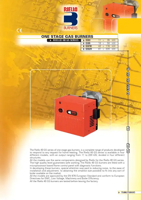
ONE STAGE GAS BURNERSRIELLO 40 GS SERIES GS3 11÷ 35kWGS5 18÷ 58kWGS10 42÷116kWGS20 81÷220kWThe Riello 40 GS series of one stage gas burners, is a complete range of products developedto respond to any request for home heating. The Riello 40 GS series is available in fourdifferent models, with an output ranging from 11 to 220 kW, divided in four different structures.All the models use the same components designed by Riello for the Riello 40 GS series.The high quality level guarantees safe working. The Riello 40 GS burners are fitted with a microprocessor based flame control panel with diagnostic functions.In developing these burners, special attention was paid to reducing noise, to the ease of installation and adjustment, to obtaining the smallest size possible to fit into any sort ofboiler available on the market.All the models are approved by the EN 676 European Standard and conform to European Directives for EMC, Low Voltage, Machinery and Boiler Efficiency.All the Riello 40 GS burners are tested before leaving the factory.TS0025UK03Since the Company is constantly engaged in the production improvement, the aesthetic and dimensional features,the technical data, the equipment and the accessories can be changed.This document contains confidential and proprietary information of RIELLO S.p.A. Unless authorised, this information shall not be divulged, nor duplicated in whole or in part.Reference conditions:Temperature: 20 °C Pressure: 1013,5 mbar Altitude: 100 m a.s.l.Noise measured at a distance of 1 meter.FIRING RATESTest conditions conforming to EN 676:Temperature: 20 °C Pressure: 1013,5 mbar Altitude: 100 m a.s.l.Useful working field for choosing the burner0,5kW5101511,51030402050102030405060000,84081624321,62,43,24,04,84820406080100120140160180200kWGS3GS5GS10GS20h P a (m b a r )m m H 2Oh P a (m b a r )m m H 2OM cal/hMcal/hMBDLE 405 - 407 - 410MBC 65 DLEM U L T I B L O CName MBC 65 DLE MBDLE 405MBDLE 405MBDLE 407MBDLE 410Code 39705693970530397050039705313970532Ø i 1/2"1/2"3/4"3/4"1"Ø o 1/2"1/2" (*)3/4"3/4"3/4"X mm 307321371371405Y mm 155186186186221Z mm122120*********W mm 3146464655YZXWThe dimensions of the gas trains vary depending on their construction features.The following table shows the dimensions of the gas trains that can be fitted to Riello 40 GS burners,intake and outlet diameters.(*) With 1/2” - 3/4” reduction nipple supplied.YZXØiWØiØo ØoThe diagrams indicate the minimum pressure drop of the burners with the various gas trains that can be combined with them; the values thus calculated represents the minimum required input pressure to the gas train.NATURAL GASLPGGS3GS3NATURAL GASLPGGS5GS5ΔPc o m b u s t i o n h e ad + g a s t r a i n c o m b u s t i o n he a dP r e s s u r e l o s sm b a rΔPc o m b u s t i o n h e ad + g a s t r a i n c o m b u s t i o n he a dP r e s s u r e l o s sm b a r4106812kcal/h x 1000kW510152025302035102015253011G20G252681012144MB C65 D LE 4106812kcal/h x 1000kW510152025302035102015253011LPG MB C65 D LE4106812kcal/h x 1000kW 10203050206020304050141640581815,5G20G25M BD L E407MB DL E 405MB C65DL E4106812kcal/h x 1000kW 10203050206020304050141640581815,5LPG M BD LE 405M B DL E 407MB C65D L E222681012161820144ΔPc o m b u s t i o n h e ad + g a s t r a i n c o m b u s t i o n he a dP r e s s u r e l o s sm b a r ΔPc o m b u s t i o n h e ad + g a s t r a i n c o m b u s t i o n he a dP r e s s u r e l o s sm b a r With installed plug (if the plug is not necessary, remove it in accordance with gas train instruction manual indication).With installed plug (if the plug is not necessary, remove it in accordance with gas train instruction manual indication).NATURAL GASLPGGS10GS10NATURAL GASLPGGS20GS20For pressure levels different from those indicated above, please contact Riello Burners T echnical Office.In LPG plants, Multibloc gas trains do not operate below 0°C.They are only suitable for gaseous LPG (liquid hydrocarbons destroy the seal materials).note Gas train MBDLE 407Code 3970531Terminal strip Plug and socket•Output kW ≤ 180 (*)Gas train MBDLE 410Code 3970532Terminal strip Plug and socket•Gas train MBDLE 405MBDLE 407MBDLE 410Code 397050039705313970532Terminal strip Plug and socket•••Output kW ≤ 80 (*)--(*) With natural gas.(*) With natural gas.ΔPc o m b u s t i o n h e ad + g a s t r a i n c o m b u s t i o n he a dP r e s s u r e l o s sm b a r ΔPc o m b u s t i o n h e ad + g a s t r a i n c o m b u s t i o n he a dP r e s s u r e l o s sm b a r kcal/h x 1000kW 116605042100709080110G20M B DL E 410556560371004045507075808590950281210164614M BD LE 407MBD LE 405kcal/h x 1000kW 116605042100709080110LPG MB DL E 41556560371004045507075808590950281210164614M B D L E 407MB DL E405M BD L E410kW 232120010081200510152025140180160220kcal/h x 100010020080120140180160703035G20G250515253035104045M BD LE 407M BD LE 410kW 232120010081200510152025140180160220kcal/h x 100010020080120140180160703035LPG M BD L E407G250268101216182014420ΔPc o m b u s t i o n h e ad + g a s t r a i n c o m b u s t i o n he a dP r e s s u r e l o s sm b a r ΔPc o m b u s t i o n h e ad + g a s t r a i n c o m b u s t i o n he a dP r e s s u r e l o s sm b a r With installed plug (if the plug is not necessary, remove it in accordance with gas train instruction manual indication).With installed plug (if the plug is not necessary, remove it in accordance with gas train instruction manual indication).The following diagram enables pressure drop in a pre-existing gas line to be calculated and to select the correct gas train.The diagram can also be used to select a new gas line when fuel output and pipe length are known. The pipe diameter is selected on the basis of the desired pressure drop. The diagram uses methane gas as reference; if another gas is used, conversion coefficient and a simple formula (on the diagram) transform the gas output to a methane equivalent (refer to figure A). Please note that the gas train dimensions must take into account the back pressure of the combustion chamber during operations.Control of the pressure drop in an existing gas line or selecting a new gas supply line.The methane output equivalent is determined by the formula fig. A on the diagram and the conversion coefficient.Once the equivalent output has been determined on the delivery scale ( ), shown at the top of the diagram, move vertically downwards until you cross the line that represents the pipe diameter; at this point, move horizontally to the left until you meet the line that represents the pipe length.Once this point is established you can verify, by moving vertically downwards, the pipe pressure drop of on the botton scale below (mbar).By subtracting this value from the pressure measured on the gas meter, the correct pressure value will be found for the choice of gas train.Example:- gas used G25- gas output9.51 mc/h - pressure at the gas meter 20 mbar - gas line length15 m- conversion coefficient0.62 (see figure A)- equivalent methane output =9.51 = 15.34 mc/h0.62- once the value of 15.34 has been identified on the output scale ( ), moving vertically downwards you cross the line that represents 1" 1/4 (the chosen diameter for the piping);- from this point, move horizontally to the left until you meet the line that represents the length of 15 m of the piping;- move vertically downwards to determine a value of 1.4 mbar in the pressure drop botton scale;- subtract the determined pressure drop from the meter pressure, the correct pressure level will be found for the choice of gas train;- correct pressure = ( 20-1.4 ) = 18.6 mbarVVVCOMBUSTION HEADThe combustion head in Riello 40 GS burners is the result of an innovative design, which allows combustion with low polluting emissions, while being easy to adapt to all the various types of boilers and combustion chambers.Combustion head FlangeVENTILATIONThe different ventilation circuits always ensure low noise levels with high performance of pressure and air delivery, inspite of their compact size.The burners are fitted with an adjustable air pressure switch,conforming to EN 676 standards.Air suction Air pressure switchDimensions of the flamem e d i a m e t e r (m )0,51DLL m axL m i nD m a xAir damper partially open (GS3, GS5)Air damper partially open (GS10, GS20)Air damper completely open (GS10, GS20)The GS3 and GS5 models are fitted with the new MG 557 microprocessor control panel.For helping the commissioning and maintenance work, there are two main elements:The lock-out reset button is the central operating element for resetting the burner control and for activating / deactivating the diagnostic functions.The multi-color LED is the central indication element for visual diagnosis and interface diagnosis.Both elements are located under the transparent cover of lock-out reset button, as showed below.There are two diagnostic choices, for indication of operation and diagnosis of fault cause:- visual diagnosis :SwitchOne stage operationIndication of operation:In normal operation, the various status are indicated in the form of colour codes according to the table below.Diagnosis of fault causes:After lock-out has occurred, the red signal lamp is steady on. In this status, the visual fault diagnosis according to the error code table can be activated by pressing the lock-out reset button for > 3 seconds.The interface diagnosis (with adapter) can be activated by pressing again the lock-out button for > 3seconds.Example of flashes sequence:Interval 2 sPress reset for 3 s Error code tableProbable causeThe flame does not stabilise at the end of the safety time:- faulty ionisation probe - faulty or soiled gas valves - neutral/phase exchange- faulty ignition transformer- poor burner regulation (insufficient gas)Min. air pressure switch does not close or is already closed before the limit thermostat closed:- air pressure switch faulty- air pressure switch incorrectly regulated Presence of flame:- in stand-by position after heat demand - during pre-purging Loss air pressure:- during pre-purging- during safety time or operationsLoss of flame 4 times during operations after 3 attempts of re-cycle:- poor burner regulation (insufficient gas)- faulty or soiled gas valves- short circuit between ionisation probe and earth - faulty ionisation probeSignal2 flashes3 flashes4 flashes 6 flashes7 flashesCOMPUTERINTERFACE ADAPTERColor code tableOperation statusStand-by Pre-purging Ignition phase Flame OK Post purgeUndervoltage, built-in fuse Fault, alarmFlame simulationColor code Led off Green Green Green Green Led off Red Led off- interface diagnosis :by the interface adapter and a PC with dedicated software.The GS10 and GS20 models are fitted with the new microprocessor control panel RMG 88.620A2 for the supervision during intermittent operation.For helping the commissioning and maintenance work, there are two main elements:The lock-out reset button is the central operating element for resetting the burner control and for activating / deactivating the diagnostic functions.The multi-color LED is the central indication element for visual diagnosis and interface diagnosis.Both elements are located under the transparent cover of lock-out reset button, as showed below.There are two diagnostic choices, for indication of operation and diagnosis of fault cause:- visual diagnosis :- interface diagnosis :by the interface adapter and a PC with dedicated software or by a predisposed flue gas analyzer (see paragraph accessories).SwitchIndication of operation :In normal operation, the various status areindicated in the form of colour codes accordingto the table below.The interface diagnosis (with adapter) can beactivated by pressing the lock-out button for> 3 seconds.Error code tablePossible cause of faultNo establishment of flame at the end of safety time : - faulty or soiled fuel valves- faulty or soiled flame detector- poor adjustment of burner, no fuel- faulty ignition equipmentFaulty air pressure monitorSimulation of flame on burner start upLoss of flame during operation :- faulty or soiled fuel valves- faulty or soiled flame detector- poor adjustment of burnerWiring error or internal fault Flash codeColor code tableOperation statusStand-byPre-purgingIgnition phaseFlame OKPoor flameUndervoltage, built-in fuseFault, alarmExtraneous lightColor code tableLED offDiagnosis of fault causes :After lock-out has occurred, the red signal lamp is steady on. In this status, the visual fault diagnosis according to the error code table can be activated by pressing the lock-out reset button for > 3 seconds. The interface diagnosis (with adapter) can be activated by pressing again the lock-out button for > 3 seconds.The flashes of red LED are a signal with this sequence :(e.g. signal with n° 3 flashes – faulty air pressure monitor)LED off3 sec. 3 sec. 3 sec.2 flashes3 flashes4 flashes7 flashes10 flashesCorrect operation for GS10 and GS20 models 0s The burner begins the ignition cycle 0s-2s Safety time2s-42s Pre-purge with the air damper open 42s IgnitionLock-out due to ignition failureIf the flame does not light within the safety limit (3s) the burner locks-out.When flame-failure occurs during working, shut down takes place within one second.Correct operation for GS3 and GS5 models 0s The burner begins the ignition cycle 0s-4s The control box waits still after the heat request 4s-8s Electrical damper time to reach the opening position 8s-48s Pre-purging time with start of the fan motor 48s-53s GS3 safety time as total ignition time 48s-51s GS5 safety time as total ignition timeLock-out due to ignition failureIf the flame does not light for 4 times within the safety limit (3s for GS5, 5s for GS3) the burner locks-out.GS3 - GS5GS10 - GS20TL M I VSOADElectrical connections must be made by qualified and skilled personnel in conformity with the local regulations in force.All the models are fitted with 7 and 6 pole sockets.WIRING DIAGRAMSControl box fitted with an ignition transformer in GS3 and GS5 models ONE STAGE OPERATIONGS3 - GS5 - GS10 - GS20In GS10 and GS20 models the control box isseparated from the ignition transformerBurner electrical wiringGas train electrical wiringBurner electrical wiringGas train electrical wiringXP6- 6 pole socket XP7- 7 pole socket X6- 6 pin plug X7- 7 pin plugB4- Working signal h1- Hour counterPG- Minimum gas pressure switchSB - Remote lock-out signal(230V - 0,5A max.)T6A - FuseTL - Limit thermostat TS - Safety thermostat V10- Safety valveV11- Adjustment valveXP6- 6 pole socket XP7- 7 pole socket X6- 6 pin plug X7- 7 pin plugB4- Working signal h1- Hour counterPG- Minimum gas pressure switchS3- Remote lock-out signal(230V - 0,5A max.)T6A - FuseTL - Limit thermostat TS - Safety thermostat V10- Safety valveV11- Adjustment valveElectrical wiring with gas leak control device (DUNGS VPS 504)PTST6AX7XP7SBN L B4ϑB4S3T2NL1T1TL P ϑh1~230V 50HzPPGV10V11X6321321XP632NPh1PPGV10V11VPSB5N L1T6T8T7X632132132NPh1PTST6AX7SBN LB4B4S3T2NL1T1ϑTL P ϑh1~230V 50HzThe following table shows the supply lead sections and types of fuse to be used.GS10 - GS20PG- Minimum gas pressure switchS3- Remote lock-out signal(220V - 0,5A max.)T6A - FuseTL - Limit thermostat TS - Safety thermostat V10- Safety valveV11- Adjustment valvePG- Minimum gas pressure switchS3- Remote lock-out signal(220V - 0,5A max.)TL - Limit thermostat TS - Safety thermostat V10- Safety valveV11- Adjustment valveP TSTLPPPGV10V11220V ~ 60HzTerminal stripL N S3T1T2P1NT6V11P2T8V12S3L N321321ϑϑT6AElectrical wiring with gas leak control device (DUNGS VPS 504)GS3Model A mm 2F L230VT61F = FuseL = Lead sectionGS5230VT61GS10230VT61GS20230VT61VPSB5NL1T6T8T7PPG321P1NP2EMISSIONSSpecial attention has been paid to noise reduction.All models are fitted with sound-proofing material inside the cover.NO EMISSIONSm g /k W h80CO EMISSIONSm g /k W h10203040NOISE EMISSIONS (sound pressure)d B (A )85909510010511011550120GS3GS5GS10GS20GS3GS5GS10GS20GS3GS5GS10GS20The emission data have been measured in the various models at maximum output, in conformity with EN 676 standard.GS3 - GS5 - GS10* With reduction nipple** Standard equipment on R40 GS3RGS20INSTALLATION DESCRIPTIONInstallation, start up and maintenance must be carried out by qualified and skilled personnel.The burner is set in factory on standard calibration (minimum output), if necessary adjustments can be made on the basis of the maximum output of the boiler.All operations must be performed as described in the technical handbook supplied with the burner.The air damper position can be easily adjusted removing the burner cover.Head setting is easy and aided by a graduated scale, a test point allows reading the air pressure in the combustion head.Riello 40 GS burners are fitted with an air pressure switch which, in accordance with EN 676 standards,can be adjusted by the installer using a graduated selector, on the basis of the effective working conditions.Maintenance is easily solved because the combustion head can be disassemblied without having to remove the burner from the boiler.BURNER SETTINGMAINTENANCEcommand kit.Extended head kitlengths.LPG kitTown gas kitGS3GS5GS10GS20BurnerT own gas kitPC interface kitTo connect the flame control panel to a personal computer for the transmission of operation, fault signals and detailed service information, an interface adapter with PC software are available.BurnerKit code30027313002719PC interface kitGS3 - GS5GS10 - GS20Kit code3000888300088930008913000893Ground fault interrupter kitA “Ground fault interrupter kit” is available as a safety device in case of electrical system fault. It is supplied with burners pin plug.BurnerKit code3001180Ground fault interrupter kitGS3 - GS5 - GS10 - GS207-pin plug kitIf necessary a 7-pin plug kit is available (in packaging of n. 5 pieces).BurnerKit code30009457-pin plug kitAll modelsContinuous ventilation kit for RMG control boxIf the burner requires continuous ventilation in the stages without flame, a special kit is available as given in the following table.BurnerKit code3010094Continuous ventilation kit for RMG control boxGS10 - GS20BALANCED FLUE VERSIONRiello 40 GS Balanced Flue versionKit code301012330101233010123GS5GS10GS20BurnerSeal control kitSeal control kitTo test the valve seals on the gas train, (except for the model with Multibloc MBC 65 DLE) a special "seal control kit" is available.GAS TRAIN ACCESSORIESMBDLE 405 - 407MBDLE 405 - 407 - 410MBDLE 407 - 410Gas trainThe R40 series balanced flue gas burner has been specifically designed to meet the increasing trend towards the use of balanced flue, otherwise known as room sealed appliances, which avoid the necessity of having a chimney to discharge the products of combustion.Balanced flue products are completely sealed from the environment in which they are installed, drawing air for combustion directly from the outside, thereby ensuring no unwelcome smells from the combustion.As a result of the burner components being completely enclosed this provides an additional benefit of low sound levels.This version is available for GS3 and GS5 only.Overall dimensions (mm)2889630891SPECIFICATIONA special index guides your choice of boiler from the Below is a clear and detailed specification description of the product.AVAILABLE BURNER MODELS GS3 1/230/50GS5 1/230/50GS10 1/230/50GS201/230/50SizeDESIGNATION OF SERIESG S Series: G3Fuel : S Natural gas1/230/50GS5 1/220/60GS10 1/220/60GS201/220/60Electrical supply to the system :1/230/501/230V/50Hz 1/220/601/220V/60HzBurnerMonoblock, gas burners, completely automatic, with one stage settings fitted with:- Fan with forward curve blades- Cover lined with sound-proofing material- Air damper, completely closed in stand by, with adjustment inside the cover- Single phase electric motor 230 V, 50 Hz- Combustion head fitted with:- stainless steel head cone, resistant to high temperatures- ignition electrodes- ionisation probe- gas distributor- flame stability disk- Adjustable air pressure switch, with graduated selector, to guarantee burner lock out in the case of insufficient combustible air- Microprocessor-based flame control panel MG 557 (with diagnostic, remote reset, continuous purge integrated, recycle, post-purge)- IP X0D electric protection level.Gas trainFuel supply line in the Multibloc configuration, fitted with:- Filter- Pressure stabiliser- Minimum gas pressure switch- Safety valve- Single stage working valve with ignition gas output regulator.Approval:- EN 676 standard.Conforming to:- 90/396/EEC (gas)- 73/23/EEC (low voltage)- 89/336/EEC (electromagnetic compatibility)- 92/42/EEC (efficiency)- 98/37/EEC (machines).Standard equipment:- Flange insulation screen- Screws and nuts for fixing the flange to the boiler- 7-pole socket- Hinge- Reduction nipple Rp 1/2” - Rp 3/8” (for R40 GS3 only)- Grommet- Instruction handbook for installation, use and maintenance- Spare parts catalogue.Available accessories to be ordered separately:- Remote reset control kit for the MG 557 control box- Extended head kit- End cone with turbulator disk- LPG kit- Town gas kit- PC interface kit- Ground fault interrupter kit- 7-pin plug kit- Continuous ventilation kit for RMG control box- Seal control kitISO 9001 Cert. n. 0061RIELLO S.p.A. - Via Ing. Pilade Riello, 5 - 37045 Legnago (VR) Italy Tel. ++39.0442630111 - Fax ++39.044221980Internet: - E-mail: info@ Since the Company is constantly engaged in the production improvement, the aesthetic and dimensional features, the technical data, the equipment and the accessories can be changed.This document contains confidential and proprietary information of RIELLO S.p.A. Unless authorised, this information shall not be divulged, nor duplicated in whole or in part.。
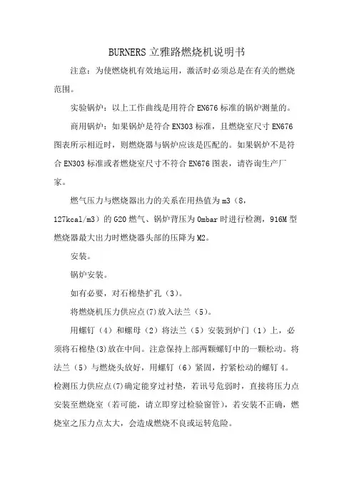
BURNERS立雅路燃烧机说明书
注意:为使燃烧机有效地运用,激活时必须总是在有关的燃烧范围。
实验锅炉:以上工作曲线是用符合EN676标准的锅炉测量的。
商用锅炉:如果锅炉是符合EN303标准,且燃烧室尺寸EN676图表所示相近时,则燃烧器与锅炉应该是匹配的。
如果锅炉不是符合EN303标准或者燃烧室尺寸不符合EN676图表,请咨询生产厂家。
燃气压力与燃烧器出力的关系在用热值为m3(8,
127kcal/m3)的G20燃气、锅炉背压为0mbar时进行检测,916M型燃烧器最大出力时燃烧器头部的压降为M2。
安装。
锅炉安装。
如有必要,对石棉垫扩孔(3)。
将燃烧机压力供应点(7)放入法兰(5)。
用螺钉(4)和螺母(2)将法兰(5)安装到炉门(1)上,必须将石棉垫(3)放在中间。
注意保持上部两颗螺钉中的一颗松动。
将法兰(5)与燃烧头放好,用螺钉(6)紧固,拧紧松动的螺钉4。
检测压力供应点(7)确定能穿过衬垫,若讯号危弱时,直接将压力点安装至燃烧室(若可能,请立即穿过检验窗管),若安装不正确,燃烧室之压力点太大,会造成燃烧不良或运转危险。
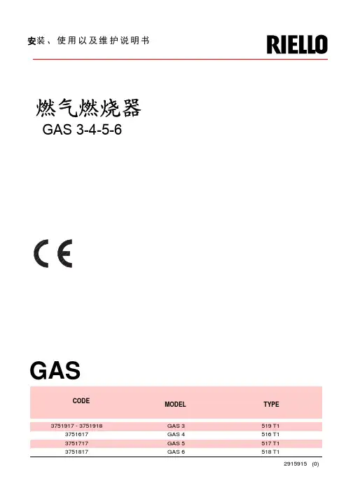
CODEMODEL TYPE3751917 - 3751918GAS 3519 T13751617GAS 4516 T13751717GAS 5517 T13751817GAS 6518 T1GAS安装、使用以及维护说明书燃气燃烧器GAS 3-4-5-6目录技术参数-------------------------------------------------------2 附件----------------------------------------------------------------3 燃烧器描述----------------------------------------------------------4 包装重量------------------------------------------------------------4 最大尺寸------------------------------------------------------------4 标准配件------------------------------------------------------------4 燃烧出力------------------------------------------------------------5 商业锅炉------------------------------------------------------------5 测试锅炉------------------------------------------------------------6 燃气压力------------------------------------------------------------6 安装-----------------------------------------------------------7锅炉板--------------------------------------------------------------7 燃烧头的长度--------------------------------------------------------7 燃烧器固定在锅炉上--------------------------------------------------7 燃烧头的设置--------------------------------------------------------8 燃气管线------------------------------------------------------------9 电气系统-----------------------------------------------------------10 首次点火前的调整---------------------------------------------------13 燃烧器启动---------------------------------------------------------13 燃烧器点火---------------------------------------------------------13 燃烧器校准---------------------------------------------------------14 1.点火输出功率--------------------------------------------------14 2.最大输出功率--------------------------------------------------15 3.空气压力开关--------------------------------------------------15 4.最低燃气压力开关----------------------------------------------15 火焰状况检查-------------------------------------------------------15 燃烧器运行---------------------------------------------------------16 最终检查-----------------------------------------------------------17 维护保养-----------------------------------------------------------17 故障表-----------------------------------------------------18 燃烧器启动循环诊断-----------------------------------------20运行故障诊断--------------------------------------------------------20技术参数型号GAS3 GAS4 GAS5 GAS6 类型 519T1 516T1 517T1 518T1 出力 KW 130-350 185-465 325-660 525-1050Mcal/h 112-301 160-400 280-570 450-900 燃料 天然气:G20-G21-G22-G23-G25G20 G25 G20 G25 G20 G25 G20 G25热值 kwh/Nm 310 8.6 10 8.6 10 8.6 10 8.6Mcal/Nm 38.6 7.4 8.6 7.4 8.6 7.4 8.6 7.4比重 kg/Nm 30.71 0.78 0.71 0.78 0.71 0.78 0.71 0.78 最大出力 Nm 3 /h 35 43 47 54 66 77 105 122 最大压力 mbar 11.1 16.4 9.8 14.5 9.8 14.5 12.3 18.2 运行 — 间断工作(每24小时停一次)—1段火工作标准应用 锅炉:热水、蒸汽、导热油炉环境温度 ℃ 0-40 助燃空气 ℃max 60 V 230~+/-10% 230-400(带零线)~+/-10% 电源 Hz 50-单相 50-三相rpm 2750 2810 2870 2840 kW 0.250 0.370 0.750 1.5 V 220 220 220/380 220/380 240 240 240/415 240/415 电机A 1.8 2.9 2.85-1.65 5.9-3.4μF 8 12.5 电容 V 450/500 400/450点火变压器 V1-V2 I1-I2230V-1×8kV1.8A-30mA电耗 kW max 0.4 0.54 0.85 1.7电保护 IP40 电磁干扰符合90/396-89/336-73/23-92/42审核标准CE 0085AQ0707(1) 参考条件:环境温度20℃,大气压力为100mbar(2) 测试点12)(A)p.4处的压力,燃烧室压力为零,燃气环2)(B)p.8开启,燃烧器输出功率最大(A)(B)(A)(B)mm A B C kg GAS 385047354532GAS 485047354538GAS 589552054341GAS 6104555554358mm A B C D E F G H I L M GAS 3205205292140Rp11/216597185775610397GAS 4205205292150Rp11/216597187775610397GAS 5226205332155Rp11/216597207810645437GAS 6258205370175Rp2195131227966770485(C)D989D990D88D231燃烧器部件说明(A )1. 燃烧器滑杆,为打开检修燃烧器用。
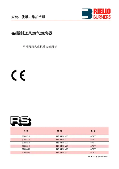
2902967 (0)安装, 使用及维护说明书强制通风燃气燃烧器编码型号类型3761900RS5920 T1一段火运行29671中文目录1.燃烧器描述一段火强制通风燃气燃烧器.1.1燃烧器附件带绝热垫的法兰. . . . . . . . . . . . . . 1 将法兰安装到锅炉上的螺栓和螺母. . . . . . . . . . . . . .. 4法兰用螺栓螺母 . . . . . . . . . . . . . 1 7针插头 . . . . . . . . . . . . . . . . . . . . . . . . . . . . . . . . . .1马达启动电容. . . . . . . . . . . . . . . 11.燃烧器描述. . . . . . . . . . . . . . . . . . . . . . . 11.1燃烧器附件. . . . . . . . . . . . . . . . . . . . . . . 12.技术参数. . . . . . . . . . . . . . . . . . . . . . . . . 22.1技术参数. . . . . . . . . . . . . . . . . . . . . . . . . 22.2外观尺寸. . . . . . . . . . . . . . . . . . . . . . . . . 22.3工作范围. . . . . . . . . . . . . . . . . . . . . . . . . 33.安装. . . . . . . . . . . . . . . . . . . . . . . . . . . . 43.1锅炉安装. . . . . . . . . . . . . . . . . . . . . . . . . 43.2燃气阀组电气连接. . . . . . . . . . . . . . . . . . 43.3燃气管线. . . . . . . . . . . . . . . . . . . . . . . . . 53.4电极定位. . . . . . . . . . . . . . . . . . . . . . . . . 53.5电气连接. . . . . . . . . . . . . . . . . . . . . . . . .64.工作 . . . . . . . . . . . . . . . . . . . . . . . . . . . .74.1燃烧调节 . . . . . . . . . . . . . . . . . . . . . . . . .74.2燃烧头设置 . . . . . . . . . . . . . . . . . . . . . . .74.3风门挡板设置. . . . . . . . . . . . . . . . . . . . . .84.4燃烧检查 . . . . . . . . . . . . . . . . . . . . . . . . .84.5燃烧器启动程序. . . . . . . . . . . . . . . . . . . .94.6空气压力开关. . . . . . . . . . . . . . . . . . . . . .95.维护 . . . . . . . . . . . . . . . . . . . . . . . . . . . .96.故障 / 解决方法 . . . . . . . . . . . . . . . . . . . .101–压力开关2–燃气阀组6 孔插座 3–带 7孔插座的控制盒4–带锁定指示灯的复位按钮 5–燃烧头安装座6–压力测试点7–带绝热垫的法兰8–风门调整机构 9–风门伺服马达燃烧器保护等级为IP 40, EN 60529.CE 认证: 参照燃气应用标准 92/42/EEC; PIN 0085BM0114.燃烧器符合下列标准:EMC 89/336/EEC, 低电压 73/23/EEC, 机械 98/37/EEC 和效率 92/42/EEC.燃气阀组符合 EN 676.图. 1SW100129672中文2.技术参数2.1技术参数对燃用LPG 可选特殊附件.2.2外观尺寸类型920 T1燃烧器出力 (1)160–330 kW-137,600–283,800 kcal/h天然气 (品种 2)净热值:8–12 kWh/Nm 3=7000–10,340 kcal/Nm 3压力:min. 20 mbar-max.100 mbar电源 单相,230V ± 10% ~ 50Hz马达运行电流 2A -2750 rpm-289 rad/s马达启动电容8 μF点火变压器初级 230V / 0.2A –次级8 kV / 12 mA电功耗0.43 kW(1) 参考条件: 温度. 20°C - 大气压力 1013 mbar – 海拔 0 m .国家ITGBDE AT DK FRNLBEIE燃气种类II2H3B/P II2H3PII2E3B/PII2H3B/PII2H3B/PII2Er3P II2L3B/P I2E(R)B,I3P II2H3P 燃气压力G20H 2020–2020–––20G25L ––––––2525–G20E––20––20/25–20/25–29673中文2.3工作范围 (参照 EN 267)实验锅炉以上工作曲线是用符合 EN 676 标准的锅炉测量得到.商用锅炉如果锅炉是符合 EN 303 标准,且燃烧室尺寸与 EN 676图表所示相近时,则燃烧器与锅炉是匹配的. 如果锅炉不是符合 EN 303 标准,且燃烧室尺寸比 EN 676图表所示更小 ,请咨询生产厂家.燃气压力与燃烧器出力的关系在用热值为10kWh/m 3(8.570 kcal/m 3)的G20燃气和锅炉背压在0 mbar 进行检测时,燃烧器最大出力时燃烧器头部的压降为 9.9 mbar(M2, 参见 3.3, P. 5).130,000290,000kW燃烧器出力kcal/h2.40.80燃烧室压力 – m b a rD62311.6170,000210,000250,0004.03.2kW燃烧器出力kcal/h632燃烧头的燃气压力 – m b a rD6232475891029674中文3.安装燃烧器的安装必须符合当地法规和标准.3.1锅炉安装♦如有必要, 对绝热垫扩孔(3) (参见图. 3).♦ 用4个螺钉 (4) 和螺母 (2) 将法兰(5)安装到炉门(1)上,必须将绝热垫 (3) 放在中间,但应保持上部两颗螺钉中的一颗松动 (4) (参见图. 2).♦用螺钉 6将法兰 5固定到燃烧头上 紧固,拧紧松动的螺钉 4.注意.: 燃烧器具有可调的燃烧头长度 (A) (参见图. 4).总之, 要保证燃烧头完全穿过锅炉前墙.3.2燃气阀组电气连接燃气阀组连接电线可从左边或右边进入燃烧器,如所示.根据进入燃烧器的方向, 带压力测试点的电缆孔堵简易电缆孔堵 (2) 可能需要互换因此, 必须确认:电缆孔堵 (1)位置正确;气管位置应正确,以保证空气通畅关造成阻塞.注意如有必要,可将气管切到正确的长度图. 2SW1003212D46051图. 529675中文3.3燃气管线符合 EN 676的燃气阀组燃气阀组单独供货, 它的调整参考附带的说明书.3.4探针 - 点火电极定位, (参见图. 7)燃气阀组连接方式应用型号编码入口出口MBDLE 410 B013970549Rp 11/4法兰 3天然气 ≤ 200kW 和 LPG 160 – 330 kWMBDLE 412 B013970550Rp 11/4法兰 3天然气 ≤ 300 kW MBDLE 415 B013970558Rp 11/2法兰 3天然气> 300 kWD52091 –供气管2 –手动球阀 (3 –燃气压力表 (4 –过滤器5 –燃气压力开关6 –安全阀7 –稳压器8 –调节阀M1–供气压力测试点M2–阀组后压力测试点29676中文3.5电气连接S7003230V ~50Hz(230V - 0.5 A max.)风门伺服马达图. 8警告; 断开连接器., 移开所有组件后, 7针 地线 (H) 拧松螺钉 (A,)紧上螺钉(A).29677中文4.工作燃烧出力燃烧器点火应在低负荷状态下进行并不超过120kW.为了测量燃烧出力:–断开离子探针电缆上的连接插头(C ) (参见电气连接P. 6); 燃烧器点火并在安全时间 (3s)过后锁定 .–进行10 次点火并连续锁定.–从流量表中读出耗气量. 该耗气量应等于或小于以下数值: G20 (天然气 H) 为0.10 Nm 3 G25 (天然气 L)为0.10 Nm 3 G31 (LPG)为0.03 Nm 3.4.1燃烧调整(参见图. 9)根据燃烧器应用于锅炉上的效率标准92/42/EEC ,调试燃烧器必须参考锅炉的使用说明书, 这一工作包括调整烟气中的 CO 和 CO 2 含量,烟温及锅炉中的平均水温.要达到所需要的出力, 要选择正确的燃烧头设定值和风门设定值.燃烧器出厂时设定在最小出力.4.2燃烧头设定根据燃烧器的出力,通过顺时针和逆时针旋转 设定螺丝 (6) 来进行,直到标尺 (2) 上的刻度值与燃烧头座 (1)的外边缘对齐.在图9中的燃烧头的设定是对应于燃烧器出力为230 kW.可见燃烧头的设定值为 4,即 标尺上的刻度值与燃烧头座的外边缘对齐 .示例:燃烧器安装在 210 kW 的锅炉.考虑到锅炉效率为 90%,燃烧器出力应为 230 kW.如图所示,燃烧头应设在 刻度4.注意此图表仅供参考;为了获得较好的燃烧效果,建议可根据锅炉调整燃烧头的设定.kcal/hkW设定点D6235SW1004图. 929678中文拆卸燃烧头组件, (参见图. 9, P. 7)按下列顺序操作:拧下螺钉(7), 断开连接插头 (3 和 5), 拆下小管 (4) 并拧松螺钉 (10)后拆下燃烧头座(1).在拆卸时不要改变燃烧头的肘型弯座 的设定.重新安装燃烧头组件, (参见图. 9, P.7)注意-在安装燃烧头时, 拧紧螺钉 (7) (不要拧太紧); 然后用力矩扳手( 3 - 4 Nm )锁紧.-如上操作确保燃烧器在运行时螺钉处不会有燃气泄露.- 如压力测点 (11) 松动,应正确固定并确保燃烧头组件(1)外部的孔 (F)安装在正确的位置上.4.3风门设定, (参见图. 9, P.7)在拧松螺母 (9)后对调节螺钉进行调整(8).燃烧器停机时风门会自动关闭,除非烟囱处最大压降大于0.5 mbar.4.4燃烧状况检查建议根据燃气种类和下表来初步设定燃烧器:离子探针电流燃烧器正常运行时控制器所需最小离子探针电流为 5 µA.一般情况下离子探针电流会远大于该值, 故不必检查. 如需要检查时, 可打开离子探针连接插头 (C) (参见页 6)串入微安电流表, (参见图. 10).在首次点火时风门设定不应小于1.EN 676过量空气系数:最大输出λ ≤ 1.2–最小输出λ ≤ 1.3燃气最大CO 2含量(0 % O 2)设定CO 2 %CO mg/kWhNO x mg/kWh λ = 1.2λ = 1.3G 2011.79.79.0 ≤100≤170G 2511.59.58.8 ≤100 ≤170G 3014.011.610.7 ≤100 ≤230G 3113.711.410.5≤100≤230注意29679中文4.5燃烧器启动程序由控制盒上的信号灯指示燃烧器锁定(4, 图. 1, P .1).在燃烧器运行时火焰消失, 燃烧器在1秒内停机.4.6空气压力开关空气压力开关的调整应在燃烧器的上述调整工作完成后进行,此时应设在初始位置.当燃烧器工作在额定出力时, 缓慢顺时针加大设定值,直至燃烧器锁定.然后逆时针旋转刻度盘将设定值减少20%, 并检查燃烧器是否能正常启动.如燃烧器锁定,应再少量减少空气压力开关的设定值.燃烧器出厂时空气压力开关在初始位置.注意:作为标准条例, 空气压力开关调整要防止当空气压力达到设定的 80% 时排烟中的 CO 超过 1% (10,000 ppm).如要检查这一点,请在烟囱中插入烟气分析仪, 缓慢关闭风机的进气口 (例如用纸板) 并检查在排烟中的CO 超过 1%之前是否会锁定.5.维护燃烧器必须由授权的和有资格的技术人员按照当地法规和标准进行定期性的维护.维护对于燃烧器运行的可靠性是必要的,可避免燃料的过量消耗以及随之而来的污染.在进行维护清理之前,必须将系统的主电源开关关掉,以切断燃烧器的电源.基本的检查有:让燃烧器不间断地运行10分钟,按本说明书检查所有组件的设置 . 然后进行燃烧测试以检查以下各项: CO 2 (%)的含量 排烟温度 CO (ppm)的含量.A296710中文6.故障 / 可能的解决方法下表所示是造成启动故障或燃烧器非正常运行等问题的原因及相应的解决方法.故障通常会造成控制盒 (4, 图. 1, P. 1)复位按钮键中的锁定指示灯亮.当锁定灯亮时,只有按复位按钮燃烧器才会重新启动,此后如果燃烧器运行正常,锁定可以归因于偶然故障.如果继续锁定,一定要查找原因,并加以解决.燃烧器启动故障故障可能原因解决方法当启动温控器闭合时,燃烧器不启动.没有电源供应.检查7针插头中的L1-N 线之间的电压是否存在.检查保险丝的状况.检查安全温控器是否锁定 .没有燃气供应.检查手动球阀是否打开 .检查阀组是否打开并且是否有短路 .燃气压力开关不闭合.调整.控制盒中的连接错误.检查并连接插头.空气压力开关在运行位置.更换压力开关.风门挡板卡住.检查电气连接.风门没全关所以燃烧器不点火: 检查.在预吹扫及点火阶段时燃烧器运行正常,但3秒后锁定.火线与零线接反.重接.没有地线或接地不良.确保接地良好.离子探针接地,离子探针未与火焰接触,离子探针与控制盒连线断开,与地短路 .检查离子探针的位置,如有必要可按本说明书进行设置.重新电气连接.更换损坏的接线.燃烧器点火延迟点火电极位置不对.按本说明书所示进行调整.空气太多.按说明书所示进行调整.阀门开度太小,燃气量不够.调整.296711中文运行中故障燃烧器锁定: – 火焰消失– 探针接地– 空气压力开关断开燃烧器停机: – 燃气压力开关断开燃烧器在预吹扫后因火焰故障而锁定.电磁阀过气量较小.检查管网压力/按说明书所示调整电磁阀.电磁阀损坏.更换.点火脉动或失败.检查接头.按说明书所示检查电极的位置.管道空气没有排净.燃气管道放散.燃烧器在预吹扫时锁定.空气压力开关不切换.压力开关故障,更换.空气压力过低, (燃烧头调整不当).火焰出现.阀门故障: 更换.压力测试点 (11, 图. 9, p 7) 位置不对. 按说明书 p 7, 节 4.2调整好位置.燃烧器不锁定,重复启动.主燃气压力接近于最低燃气压力开关所限定的数值.阀门开启后燃气压力的突降,从而引起压力开关的暂时断开.阀门立刻关闭,燃烧器停机.压力又升高,压力开关再次闭合,重复点火周期,该过程没有休止地进行.减小最低燃气压力开关的设定值.故障可能原因解决方法。
2915915 (0)CODEMODELTYPE3751917 - 3751918GAS 3519 T13751617GAS 4516 T13751717GAS 5517 T13751817GAS 6518 T1GAS安装、使用以及维护说明书燃气燃烧器GAS 3-4-5-6目录技术参数-------------------------------------------------------2附件----------------------------------------------------------------3燃烧器描述----------------------------------------------------------4包装重量------------------------------------------------------------4最大尺寸------------------------------------------------------------4标准配件------------------------------------------------------------4燃烧出力------------------------------------------------------------5商业锅炉------------------------------------------------------------5测试锅炉------------------------------------------------------------6燃气压力------------------------------------------------------------6安装-----------------------------------------------------------7锅炉板--------------------------------------------------------------7燃烧头的长度--------------------------------------------------------7燃烧器固定在锅炉上--------------------------------------------------7燃烧头的设置--------------------------------------------------------8燃气管线------------------------------------------------------------9电气系统-----------------------------------------------------------10首次点火前的调整---------------------------------------------------13燃烧器启动---------------------------------------------------------13燃烧器点火---------------------------------------------------------13燃烧器校准---------------------------------------------------------141.点火输出功率--------------------------------------------------142.最大输出功率--------------------------------------------------153.空气压力开关--------------------------------------------------154.最低燃气压力开关----------------------------------------------15火焰状况检查-------------------------------------------------------15燃烧器运行---------------------------------------------------------16最终检查-----------------------------------------------------------17维护保养-----------------------------------------------------------17故障表-----------------------------------------------------18 燃烧器启动循环诊断-----------------------------------------20运行故障诊断--------------------------------------------------------201技术参数型号GAS3 GAS4 GAS5 GAS6类型519T1 516T1 517T1 518T1出力KW 130-350 185-465 325-660 525-1050 Mcal/h 112-301 160-400 280-570 450-900燃料天然气:G20-G21-G22-G23-G25G20 G25 G20 G25 G20 G25 G20 G25热值kwh/Nm3 10 8.6 10 8.6 10 8.6 10 8.6Mcal/Nm38.6 7.4 8.6 7.4 8.6 7.4 8.6 7.4比重kg/Nm30.71 0.78 0.71 0.78 0.71 0.78 0.71 0.78最大出力Nm3/h 35 43 47 54 66 77 105 122 最大压力mbar 11.1 16.4 9.8 14.5 9.8 14.5 12.3 18.2运行—间断工作(每24小时停一次)—1段火工作标准应用锅炉:热水、蒸汽、导热油炉环境温度℃ 0-40助燃空气℃max 60V 230~+/-10% 230-400(带零线)~+/-10% 电源Hz 50-单相 50-三相rpm 2750 2810 2870 2840kW 0.250 0.370 0.750 1.5V 220 220 220/380 220/380240 240 240/415 240/415 电机A 1.8 2.9 2.85-1.65 5.9-3.4μF 8 12.5电容V 450/500 400/450点火变压器V1-V2I1-I2 230V-1×8kV 1.8A-30mA电耗kW max 0.4 0.54 0.85 1.7电保护 IP40电磁干扰符合90/396-89/336-73/23-92/42审核标准CE 0085AQ0707(1)参考条件:环境温度20℃,大气压力为100mbar(2)测试点12)(A)p.4处的压力,燃烧室压力为零,燃气环2)(B)p.8开启,燃烧器输出功率最大重要提示:由安装者负责其它不在此说明书中提到的安全设备。

燃气燃烧器GULLIVER BS3-4/M目录1..燃烧器描述------------------------------------------------------11.1燃烧机附件--------------------------------------------------11. 2 燃烧机随机附件2..技术资料---------------------------------------------------------22.1技术资料-----------------------------------------------------22外观尺寸-----------------------------------------------------22.3燃烧范围-----------------------------------------------------33..安装--------------------------------------------------------------43.1锅炉安装-----------------------------------------------------43.2瓦斯电磁阀-----------------------------------------------------43.3燃气供应管路------------------------------------------------------53.4探针-电极定位---------------------------------------------------54..线路图--------------------------------------------------------------74.1内部线路图-----------------------------------------------------74.2外部线路图-----------------------------------------------85..工作--------------------------------------------------------------75.1燃烧调整-----------------------------------------------------75.2燃烧头设定-----------------------------------------------85.3风门档板设定-------------------------------------------------85.4第一次激活-----------------------------------------------------95.5燃烧检查-----------------------------------------------------95.6空气压力开关-----------------------------------------------------95.7瓦斯压力开关-----------------------------------------------------95.8燃烧器激活图-----------------------------------------------------96.维护---------------------------------------------------------------9 7故障及解决办法-------------------------------------------------10燃烧器描述(图1)燃烧器符合IP40,90/396/EEC; PIN 0085BN0609电保护等级◆CE标志指90/396/EEC;PIN燃气使用标准◆符合标准:EMC89/336/EEC,73/23/EEC,98/37/EEC,92/42/EEC.◆阀门组符合EN676.1 –带绝热石棉垫的法兰2 –燃烧头3 –燃烧程控器4 –带锁定灯的覆归按钮5 –风门调节控制器6 –燃烧头设定螺丝7 –空气压力开关8 –燃烧室压力测点(连接瓦斯电磁阀) 9 –控制燃烧器双段/比例输出的4孔插座10 –7孔插座(燃烧机供给)11–电磁阀组的6孔插座12 –压力测点(连接瓦斯电磁阀)13 –手动或自动运转开关(MAN / AUT), 增加或减少输出功率开关(+/-)2.1 燃烧器附件带绝热石棉垫的法兰1个4孔插头1个安装法兰用螺钉螺母4个G1/8结合点1个法兰用螺钉螺母1套7孔插头1个蓝色塑料管1个2.2 燃烧器选用配件(另购)3.2外观尺寸注意: 为使燃烧机有效地运用,激活时必须总是在有关的燃烧范围。
. 轻油燃烧器RL 28-38-50目录技术说明------------------------------------------------------------------------------------------------------1 技术参数-------------------------------------------------------------------------------------------------------------------1燃烧器描述----------------------------------------------------------------------------------------------------------------2包装-重量----------------------------------------------------------------------------------------------------------------2最大尺寸-----------------------------------------------------------------------------------------------------------------2标准配件-------------------------------------------------------------------------------------------------2燃烧出力------------------------------------------------------------------------------------------------------------------3测试锅炉------------------------------------------------------------------------------------------------------------------3安装----------------------------------------------------------------------------------------------------------4 锅炉法兰-----------------------------------------------------------------------------------------------------------------4燃烧头长度---------------------------------------------------------------------------------------------------------------4燃烧器与锅炉的连接-----------------------------------------------------------------------------------------------------4 1级,2级喷嘴的选择----------------------------------------------------------------------------------------------------4喷嘴的安装---------------------------------------------------------------------------------------------------------------5点火前的设置-------------------------------------------------------------------------------------------------------------5油路连接------------------------------------------------------------------------------------------------------------------6电气连接------------------------------------------------------------------------------------------------------------------6泵的起动------------------------------------------------------------------------------------------------------------------7燃烧器调整---------------------------------------------------------------------------------------------------------------8燃烧特性------------------------------------------------------------------------------------------------------------------9最终检查------------------------------------------------------------------------------------------------------------------9附录---------------------------------------------------------------------------------------------------------10 燃料供给----------------------------------------------------------------------------------------------------------------10喷嘴----------------------------------------------------------------------------------------------------------------------11电气系统-----------------------------------------------------------------------------------------------------------------12状态/LED显示板--------------------------------------------------------------------------------------------------------13燃烧器运行--------------------------------------------------------------------------------------------------------------14泵------------------------------------------------------------------------------------------------------------------------15维护保养----------------------------------------------------------------------------------------------------------------15按空气密度计算燃烧出力-----------------------------------------------------------------------------------------------17故障维修-----------------------------------------------------------------------------------------------------------------18本文中所提到的图形如下标识:1)(A)=图A的第1部分,与文本同页1)(A)p.4=图A的第1部分,页号4技术说明参考条件:1. 环境温度为20℃,压力为1bar,海拔为100m。
燃气燃烧器RS28/1-38/1目录技术参数--------------------------------------------------------------------------------------------------------------------1 变型燃烧头-----------------------------------------------------------------------------------------------------------------1 LGP组件--------------------------------------------------------------------------------------------------------------------1 燃烧器描述-----------------------------------------------------------------------------------------------------------------2 包装-重量-----------------------------------------------------------------------------------------------------------------2 最大尺寸---------------------------------------------------------------------------------------------------------------------2 标准附件---------------------------------------------------------------------------------------------------------------------2 燃烧出力---------------------------------------------------------------------------------------------------------------------3 测试锅炉---------------------------------------------------------------------------------------------------------------------3 商用锅炉---------------------------------------------------------------------------------------------------------------------3 燃气压力---------------------------------------------------------------------------------------------------------------------4 安装---------------------------------------------------------------------------------------------------------------------------5 锅炉板------------------------------------------------------------------------------------------------------------------------5 燃烧头长度------------------------------------------------------------------------------------------------------------------5 燃烧器固定到锅炉上------------------------------------------------------------------------------------------------------5 设定燃烧头------------------------------------------------------------------------------------------------------------------6 气体管线------------------------------------------------------------------------------------------------------------------------7 电气系统--------------------------------------------------------------------------------------------------------------------8 点火前调整-----------------------------------------------------------------------------------------------------------------11 燃烧器起动-----------------------------------------------------------------------------------------------------------------11 燃烧器点火-----------------------------------------------------------------------------------------------------------------11 燃烧器校准-----------------------------------------------------------------------------------------------------------------12 1- 点火输出功率----------------------------------------------------------------------------------------------------------12 2-输出功率-------------------------------------------------------------------------------------------------------12 3-输出功率------------------------------------------------------------------------------------------------------13 4-输出功率---------------------------------------------------------------------------------------------------------13 5-空气压力开关---------------------------------------------------------------------------------------------------------14 6-最低燃气压力开关--------------------------------------------------------------------------------------------------14 火焰有无检查------------------------------------------------------------------------------------------------------------14 燃烧器运行----------------------------------------------------------------------------------------------------------------15 最终检查------------------------------------------------------------------------------------------------------------------16 维护-------------------------------------------------------------------------------------------------------------------------16 故障-可能的原因-排障建议-----------------------------------------------------------------------------------------18本文中所提到的图形如下标识:1)(A)=图A的第1部分,与文本同页1)(A)p.4=图A的第1部分,页号4技术参数2) 测试点8)(A)p.2处的压力,燃烧室压力为零,燃气环2)(B)p.6开启,燃烧器输出功率最大。
强制通风燃气燃烧器平滑二段火或比例调节运行代码型号类型3753883GAS 8 P/M538 T80 3753884GAS 8 P/M538 T80 3754083GAS 9 P/M540 T80 3754084GAS 9 P/M540 T80 3754185GAS 10 P/M541 T80 3754186GAS 10 P/M541 T80 3754187GAS 10 P/M541 T80 3754188GAS 10 P/M541 T80目录 页码1概述. . . . . . . . . . . . . . . . . . . . . . . . . . . . . . . . . . . . . . . . . . . . . . .31.1技术参数 . . . . . . . . . . . . . . . . . . . . . . . . . . . . . . . . . . . . . . . . . . .31.2可选型号 . . . . . . . . . . . . . . . . . . . . . . . . . . . . . . . . . . . . . . . . . . .31.3燃烧器描述 . . . . . . . . . . . . . . . . . . . . . . . . . . . . . . . . . . . . . . . . .41.4包装 重量. . . . . . . . . . . . . . . . . . . . . . . . . . . . . . . . . . . . . . . . . . .41.5最大尺寸 . . . . . . . . . . . . . . . . . . . . . . . . . . . . . . . . . . . . . . . . . . .41.6标准配件 . . . . . . . . . . . . . . . . . . . . . . . . . . . . . . . . . . . . . . . . . . .41.7附件. . . . . . . . . . . . . . . . . . . . . . . . . . . . . . . . . . . . . . . . . . . . . . .51.8出力图. . . . . . . . . . . . . . . . . . . . . . . . . . . . . . . . . . . . . . . . . . . . .61.9测试锅炉 . . . . . . . . . . . . . . . . . . . . . . . . . . . . . . . . . . . . . . . . . . .61.10燃气压力 . . . . . . . . . . . . . . . . . . . . . . . . . . . . . . . . . . . . . . . . . . .62安装. . . . . . . . . . . . . . . . . . . . . . . . . . . . . . . . . . . . . . . . . . . . . . .72.1锅炉板. . . . . . . . . . . . . . . . . . . . . . . . . . . . . . . . . . . . . . . . . . . . .72.2燃烧头长度 . . . . . . . . . . . . . . . . . . . . . . . . . . . . . . . . . . . . . . . . .72.3将燃烧器固定在锅炉上 . . . . . . . . . . . . . . . . . . . . . . . . . . . . . . . .82.4设置燃烧头 . . . . . . . . . . . . . . . . . . . . . . . . . . . . . . . . . . . . . . . . .82.5燃气管路 . . . . . . . . . . . . . . . . . . . . . . . . . . . . . . . . . . . . . . . . . . .92.6电气设备,工厂设置 . . . . . . . . . . . . . . . . . . . . . . . . . . . . . . . . .102.7电气设备,安装人员设置. . . . . . . . . . . . . . . . . . . . . . . . . . . . . .103点火前的控制与校准 . . . . . . . . . . . . . . . . . . . . . . . . . . . . . . . . .133.1锅炉. . . . . . . . . . . . . . . . . . . . . . . . . . . . . . . . . . . . . . . . . . . . . .133.2燃气管道 . . . . . . . . . . . . . . . . . . . . . . . . . . . . . . . . . . . . . . . . . .133.3助燃空气 . . . . . . . . . . . . . . . . . . . . . . . . . . . . . . . . . . . . . . . . . .143.4电气系统 . . . . . . . . . . . . . . . . . . . . . . . . . . . . . . . . . . . . . . . . . .143.5燃烧器启动 . . . . . . . . . . . . . . . . . . . . . . . . . . . . . . . . . . . . . . . .144燃烧器点火 . . . . . . . . . . . . . . . . . . . . . . . . . . . . . . . . . . . . . . . .155燃烧器校准 . . . . . . . . . . . . . . . . . . . . . . . . . . . . . . . . . . . . . . . .155.1设置燃烧头 . . . . . . . . . . . . . . . . . . . . . . . . . . . . . . . . . . . . . . . .155.2设置伺服马达. . . . . . . . . . . . . . . . . . . . . . . . . . . . . . . . . . . . . . .165.3设置燃气压力. . . . . . . . . . . . . . . . . . . . . . . . . . . . . . . . . . . . . . .175.4设置燃烧器出力. . . . . . . . . . . . . . . . . . . . . . . . . . . . . . . . . . . . .175.4.1设置最大出力. . . . . . . . . . . . . . . . . . . . . . . . . . . . . . . . . . . . . . .185.4.2设置最小出力. . . . . . . . . . . . . . . . . . . . . . . . . . . . . . . . . . . . . . .195.4.3设置中间出力. . . . . . . . . . . . . . . . . . . . . . . . . . . . . . . . . . . . . . .205.5设置空气压力开关. . . . . . . . . . . . . . . . . . . . . . . . . . . . . . . . . . .205.6设置最大燃气压力开关 . . . . . . . . . . . . . . . . . . . . . . . . . . . . . . .205.7设置最低燃气压力开关 . . . . . . . . . . . . . . . . . . . . . . . . . . . . . . .205.8设置燃烧 . . . . . . . . . . . . . . . . . . . . . . . . . . . . . . . . . . . . . . . . . .215.9火焰监测 . . . . . . . . . . . . . . . . . . . . . . . . . . . . . . . . . . . . . . . . . .216运行. . . . . . . . . . . . . . . . . . . . . . . . . . . . . . . . . . . . . . . . . . . . . .227最终控制装置. . . . . . . . . . . . . . . . . . . . . . . . . . . . . . . . . . . . . . .238燃气流量测量. . . . . . . . . . . . . . . . . . . . . . . . . . . . . . . . . . . . . . .239燃烧器不运行. . . . . . . . . . . . . . . . . . . . . . . . . . . . . . . . . . . . . . .2310维护. . . . . . . . . . . . . . . . . . . . . . . . . . . . . . . . . . . . . . . . . . . . . .2511附表. . . . . . . . . . . . . . . . . . . . . . . . . . . . . . . . . . . . . . . . . . . . . .26注意事项注意事项::在文本中所提及的图形标识按如下说明:1)(A)= 图(A)的第1部分,与文本的同页;1)(A)p.4= 图(A)的第1部分,页码为4;1)= 所提及最后一张图的第1部分。
燃烧器基本技术意大利利雅路股份公司北京代表处利雅路燃烧器可应用于各种锅炉、加热器、窑炉、烘干设备,产品丰富。
可分为30多个系列,130多种型号。
输出功率从17KW到32000KW。
分别可燃烧轻油、燃气和重油或双燃料,部分机型还可以燃烧生物燃料。
按燃料划分:轻油系列燃气系列重油系列油气两用系列。
利雅路燃烧器可应用于各种锅炉、加热器、窑炉、烘干设备,产品丰富。
可分为30多个系列,130多种型号。
输出功率从17KW到32000KW。
分别可燃烧轻油、燃气和重油或双燃料,部分机型还可以燃烧生物燃料。
按出力划分:家用0.1T/H ~0.5T/H (17~300KW)商用0.5T/H ~2T/H (300~1500KW)工业应用 2 T/H 以上(>1500KW)利雅路燃烧器可应用于各种锅炉、加热器、窑炉、烘干设备,产品丰富。
可分为30多个系列,130多种型号。
输出功率从17KW到32000KW。
分别可燃烧轻油、燃气和重油或双燃料,部分机型还可以燃烧生物燃料。
按排放标准:CALSS ICLASS II CLASS II(低NOx)EN 676 –燃气燃烧器-NOx排放标准Class 1 170 (mg/kWh) Class 2 120 (mg/kWh) Class 3 80 (mg/kWh)EN 267 –燃油燃烧器-NOx排放标准Class 1 250 (mg/kWh) Class 2 185 (mg/kWh) Class 3 120 (mg/kWh)燃烧器的组成部分电控系统送风系统点火系统监测系统燃料系统送风系统作用:送入一定风速和风量的空气其主要部件:壳体、风机马达、风机叶轮、风枪火管、风门控制器、风门档板、稳焰盘送风系统壳体:多数采用分体式壳体,一般为枪式。
壳体的组成材料一般为高强度轻质合金铸件风枪火管:引导气流和稳定风压外套式法兰与炉口联接。
高强度和耐高温的合金钢风门控制器:驱动装置液压驱动控制器和伺服马达驱动控制器风门档板:控制进风量的大小塑档板一般为单片形式,合金档板有单片、双片、三片等稳焰盘:特殊的结构能够产生旋转气流,有助于空气与燃料的充分混合调节二次风量的作用燃料系统燃油燃烧器:油管及接头、油泵、电磁阀、喷嘴、重油预热器燃气燃烧器:过滤器、调压器、电磁阀组、点火电磁阀组燃料系统油管及接头油泵J型、E型和TA型,油泵内有过滤器、压力调节阀和截止阀0.4bar,10~24bar ,90℃电磁阀:控制油路的通断,多为二通阀和三通阀喷嘴:雾化油滴。
利雅路燃烧器安装说明标准化管理处编码[BBX968T-XBB8968-NNJ668-MM9N]
一、喷嘴的安装:
1、核对喷嘴型号,每个数值的油耗为4.2KG/H。
2、取下末端锥筒
3、取下风量调节筒
4、取下稳焰盘组件
5、取下塑料塞子后,用16mm扳手将喷嘴进行安装。
请勿使用任何密封材料,注意不要损坏喷嘴的密封垫。
安装时喷嘴必须拧到位,但不要拧脱扣。
6、点火装置调节(一般情况不需要调节)
二、燃烧头调节(一般不需要调节)
根据出力大小,按说明书提供图表调整刻度盘至相应位置
三、油路安装
1、按照箭头方向安装进油管和回油管,过滤器安装在进油管路上。
四、电气连接
1、交流220V供电,接X7插头。
2、公司一般通过控制电源通断控制燃烧器工作,需将X7插头T1、T2端子短接。
3、如需二段火运行,需将X4插头T6、T8端子短接。
注:小型燃烧机(G20)接线端子⊙为故障输出的指示灯接线端子,千万不要接地。
五、启动
1、检查油路、电气连接是否正确。
2、松开油泵下的螺栓V,排除泵中的空气。
3、启动燃烧器,油泵方向必须与所标示一致。
如果螺栓V处有油漏出,油泵注油成功。
关闭燃烧器,拧紧螺栓。
六、烟度调节
黑烟为燃烧不充分,需调大风门。
白烟为风量过大,需调小风门。
二段火工作时的风门调节一般调整一段火风门是燃烧机顺利点火为宜,调整二段火风门至要求烟度。
调整完成后,拧紧防活动螺丝。