东芝笔记本电脑维修手册 Tecra_A1_Series
- 格式:pdf
- 大小:4.72 MB
- 文档页数:11
东芝服务便携手册——长江Ⅳ篇e-STUDIO223/243/225/245全国服务部东芝泰格信息系统(深圳)有限公司目录一、规格参数 (3)(一)规格参数清单 (3)(二)耗材清单 (3)(三)选购件清单 (4)(四)PM零件清单 (5)二、错误代码及故障排错参考 (6)三、维修模式 (11)(一)低版本维修模式 (11)(二)高版本维修模式 (11)四、输入测试模式(03/04测试模式) (12)(一)低版本03输入模式 (12)(二)高版本模式04-传感器测试模式 (13)五、输出测试模式 (15)(一)低版本04测试模式/高版本13功能测试中10输出测试 (15)六、列表打印模式 (16)(一)低版本1+3开机 (16)(二)高版本列表打印模式 (16)七、常用05/08代码 (17)(一)常用05调整代码 (17)(二)常用08设置代码 (20)八、USB升级模式(仅限高版本机器) (22)(一)升级方式 (22)(二)升级文件类型 (22)(三)UBS升级步骤 (23)(四)升级完成后相关检查 (24)九、电路板更换 (25)(一)主板更换步骤 (25)(二)SRAM更换步骤 (25)一、规格参数注意:随机墨粉为5K容量*传真卡6AH00000531对应e-STUDIO223:C3B226612-•、e-STUDIO243:C3B226541-、e-STUDIO225:C3A220422-•、e-STUDIO245:C3B222474- 序列号之后的机器二、错误代码及故障排错参考三、维修模式(二)e-STUDIO225/245高版本维修模式:四、输入测试模式(03/04测试模式)(二)e-STUDIO225/245高版本模式04-传感器测试模式:(一)低版本1+3开机101:功能(FUNC, 05/08)数据列表102:系统设置列表103:内存信息转储列表(二)高版本列表打印模式七、常用05/08代码八、USB升级模式(仅限e-STUDIO 225/245)对于e-STUDIOS225/245,如果已经安装了网络打印套件GA-1192,则可以通过把存有Firmware数据的USB存储装置连接到GA-1192控制线路板上的USB接口,接通电源来对Firmware进行更新。
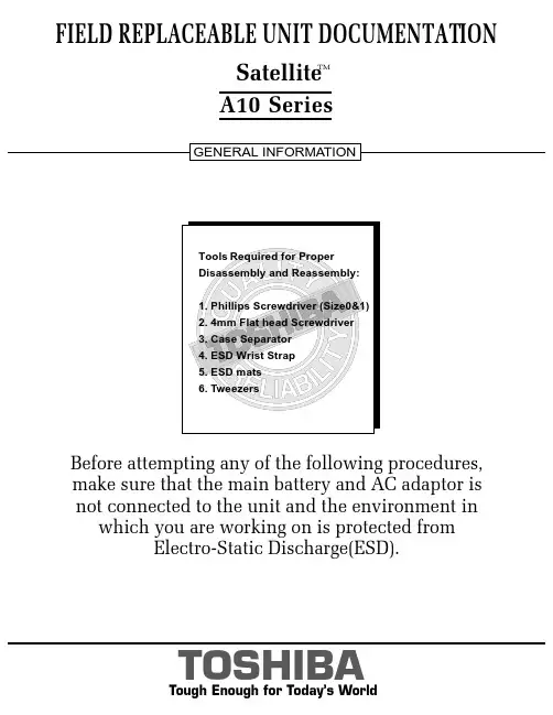
FIELD REPLACEABLE UNIT DOCUMENTATIONSatellite TMA10 Seriesnot connected to the unit and the environment in which you are working on is protected fromElectro-Static Discharge(ESD).A10 SeriesBATTERY PACK REMOVAL1. Turn the computer upside down as shown.2. Slide the battery release lever in the direction of the arrow.3. Lift out the battery pack assy .HDD REMOVAL1. Turn the computer upside down.2. Remove two M2.5x16 black flat head screws securing HDD slot cover and pull out the cover ..4. Separate the battery pack from the battery cover.OPTIONAL PC CARD REMOVAL 1. Press the eject button of the PC Card you want to remove.2. Press the extended eject button to pop the PC card out slightly.3. Grasp the PC Card and pull it outNOTE : Before removing any PCMCIA device, make sure it is “STOPPED” in the PC Card Manager.A10 SeriesBattery packBattery cover6. Remove four M3x4 brass flat head screws securing the HDD bracket to the drive.4. Slowly spread out the memory clips and pull the memory module out of the connector on a 45 degree angle.3. Remove one M2.5x5 black flat head screw securing the HDD assembly.4. Grasp the HDD bracket handle and pull to disconnect the HDD assembly.5. Lift the HDD assembly out of the HDD bay.MEMORY MODULE REMOV AL1. Turn the computer upside down.2. Remove one M2.5x4 black flat head screwsecuring the memory cover.3. Lift out the cover .A10 SeriesM2.5x5 black flat head screwHDD assyHDD bracket handleM3x4 brass flat head screwsM2.5x4 black flat head screwMemory moduleMemory clipsWIRELESS LAN CARD REMOVAL1. Turn the computer upside down.2. Remove one M2.5x4 black flat head screw securing the Mini PCI slot cover.3. Lift out the PCI slot cover .4. Peel off the glass tapesecuring the mini coax cables.5. Disconnect thewhite mini coax cable from main connector and the black mini coax cable from aux connector.6. Gently press out the Mini PCI slot clips and pull theMini PCI card out of the connector on a 30 degree angle.MODEM BOARD REMOVAL1. Remove one M2.5x4 black flat head screw securing the modem slot cover.2. Insert your finger nail or the case separator into the notched side of the cover and lift up to release the latch securing the modem slot cover.3. Remove two M2x4 black screws securing the modem board.4. Gently lift up the modem board to disconnect it from the system board and disconnect the MJ harness from JP1 on the modem board.A10 SeriesMini PCI cardPCI clipsWhite mini coax cable Black mini coax cableModem slot cover M2.5x4 black flat head screws ModemMJ Harness1. Turn the computer upside down.2. Remove two M2.5x5 black flat head screws and one M2.5x16 black flat head screw securing the modem cover.3. Remove the modem cover .COOLING MODULE REMOVALCOOLING MODULE REMOVAL1. Disconnect the fan cable fromPJ8770 on the system board.2. Remove two M2.5x5 black flat head screws securing the fan.3. Lift out the fan..2. Lift out the CPU .A10 SeriesM2.5x5 black flat head screwsCooling module brace Cooling module1. Remove M2x6 brass screws securing the cooling module brace.2. Lift out the cooling module brace .3. Lift out the cooling module .CPUClose PJ8770FanFan cable1. Open the display panel.2. Using the case separator, unlatch the keyboard holder as shown above.KEYBOARD REMOVAL3. Remove two M2.5x2.8 black flat head screwssecuring the keyboard.4. Remove one M2.5x2.8 black flat head screw securing the keyboard holder plate.5. Lift out the keyboard holder plate .6. Lift out the keyboard and set it on the palm rest.7. Remove one M2.5x8 black flat head screw securing the keyboard support plate.8. Lift out the keyboard support plate .KEYBOARD REMOVALKeyboard9. Lay the keyboard as shown above.10. Disconnect the keyboard cable from PJ3200 on the system board.11. Lift out the keyboard .A10 SeriesKeyboard holderKeyboard holder plateM2.5x4 black flat head screwM2.5x8 black flat head screwKeyboard support plateKeyboard cableA10 SeriesCD-R/W/DVD-ROM DRIVE REMOVAL1. Turn the computer upside down.2. Remove one M2.5x5 black flat head screw securing the CD-R/W/DVD-ROM drive.drive bay.5. Remove two M2x1.7 brass screws securing the CD-R/W/DVD-ROM drive bracket and lift out the bracket6. Remove one M2x3 silver screw securing the side bracket and lift out the bracket.CD-R/W/DVD-ROM drive CD-R/W/DVD-ROM DRIVE REMOVAL1. Turn the computer upside down and remove the following twenty screws:- 7 M2.5x5 black flat head screws - 13 M2.5x16 black flat head screwsCD-R/W/DVD-ROM driveM2.5x5 black flat head screw M2x1.7 brass screwsM2x3 silver screwSide bracketCD-RW/DVD drive bracketM2.5x16 black flat head screwsA10 SeriesTOP COVER REMOVAL1. Disconnect the LCD/FL cable from PJ5600 on the system board.2. Lift up the plastic insulator covering the Left/Right speaker cables and disconnect the Left/Rightspeaker cables from PJ6000/PJ6001.3. Remove one M2.5x8 black flat head screw securingtop cover and lift out the top cover assembly .TOUCH PAD ASSEMBLY REMOVAL1. Disconnect the touch pad cable from PJ3201 on the system board.2. Remove one M2.5x5 black flat head screw securingthe touch pad assembly.3. Lift out the touch pad assembly .PJ2004Touch pad assembly cableBAT CON HOLDER REMOVAL 1. Remove two M2.5x8 black flat head screw securing the bat con holder.2. Lift out the bat con holder from the system board.M2.5x8 black flat head screwsSYSTEM BOARD REMOVAL1. Peel off the glass tape securing the RTC battery cable.2. Remove two M2.5x5 black flat head screw securing the system board.3. Lift up the system boardfrom the right hand side and lift it out.A10 SeriesDC-IN JACK/RTC BATTERY REMOVAL1. Peel off the glass tape securing the DC-In jack/ RTC battery harness.2. Disconnect the DC-In jack harness from PJ8800 on the system board.3. Disconnect the RTC battery harness fromPJ8790 on the system board .RTC battery harnessDC-InJack harnessPJ8800Glass tapeFL INVERTER AND 14” LCD REMOV ALFIELD REPLACEABLE UNIT DOCUMENTATIONSatellite TMTOSHIBATough Enough for Today’s World14” DISPLAY MASK REMOVAL1. Removedisplay assembly using a pair of fine-tipped tweezers.2. Remove two M2.5x6 black flat head screws securing the display mask.3. There are 24 latches securing the display mask .Carefully insert your fingers between the mask and the LCD panel and pry open the latches starting from the bottom six latches , to the five latches on the right andleft sides , ending with the six top latches .1. Remove one M2x4 brass flat head screwsecuring the FL inverter board.2. Carefully lift up the FL inverter board anddisconnect the LCD /FL cable from CN1 and the FL cable from CN2..3. Remove four mask seals to expose four screws securing the LCD module assembly.4. Remove four M2X4 brass flat head screws securing the LCD module assembly.5. Carefully rotate out the top of the LCD module enough to access the display cable.6. Peel off the tape securing the LCD/FL cable and disconnect the cable.7. Remove four M2x3 silver flat head screws securing the left/right LCD brackets.A10 SeriesLatch。
计算机硬件维修手册电脑出现的故障原因扑朔迷离,让人难以捉摸。
并且由于Windows操作系统的组件相对复杂,电脑一旦出现故障,对于普通用户来说,想要准确地找出其故障的原因几乎是不可能的。
那么是否是说我们如果遇到电脑故障的时候,就完全束手无策了呢?其实并非如此,使电脑产生故障的原因虽然有很多,但是,只要我们细心观察,认真总结,我们还是可以掌握一些电脑故障的规律和处理办法的。
在本期的小册子中,我们就将一些最为常见也是最为典型的电脑故障的诊断、维护方法展示给你,通过它,你就会发现——解决电脑故障方法就在你的身边,简单,但有效!电脑是由各种配件组合而成的,下面,我们就根据组成电脑的各个部件分别对其经常出现的故障进行分析。
计算机硬件维修手册(主板篇)主板是整个电脑的关键部件,在电脑起着至关重要的作用。
如果主板产生故障将会影响到整个PC机系统的工作。
下面,我们就一起来看看主板在使用过程中最常见的故障有哪些。
常见故障一:开机无显示电脑开机无显示,首先我们要检查的就是是BIOS。
主板的BIOS中储存着重要的硬件数据,同时BIOS也是主板中比较脆弱的部分,极易受到破坏,一旦受损就会导致系统无法运行,出现此类故障一般是因为主板BIOS被CIH病毒破坏造成(当然也不排除主板本身故障导致系统无法运行。
)。
一般BIOS被病毒破坏后硬盘里的数据将全部丢失,所以我们可以通过检测硬盘数据是否完好来判断BIOS是否被破坏,如果硬盘数据完好无损,那么还有三种原因会造成开机无显示的现象:1. 因为主板扩展槽或扩展卡有问题,导致插上诸如声卡等扩展卡后主板没有响应而无显示。
2. 免跳线主板在CMOS里设置的CPU频率不对,也可能会引发不显示故障,对此,只要清除CMOS即可予以解决。
清除CMOS的跳线一般在主板的锂电池附近,其默认位置一般为1、2短路,只要将其改跳为2、3短路几秒种即可解决问题,对于以前的老主板如若用户找不到该跳线,只要将电池取下,待开机显示进入CMOS设置后再关机,将电池上上去亦达到CMOS 放电之目的。
东芝笔记本故障怎么维修推荐文章笔记本怎么提高性能热度:笔记本怎么解除WiFi密码热度:惠普笔记本无线网卡驱动异常怎么办热度:惠普笔记本怎么样热度:笔记本电脑键盘灯在哪里怎么打开热度:在我们面对着一年春夏秋冬的四个季节里面,由于我们的东芝笔记本需要适应各个气候所造成的影响,所以在每个季节当中,我们都需要对我们的东芝笔记本进行适当的维修与检测。
这样,东芝笔记本的散热器才能适应环境得以更长久健康地运行,然后我们东芝笔记本的寿命才能更长。
希望大家能从店铺给大家推荐的文章当中,确确实实能学到修复东芝笔记本的方法。
1.东芝笔记本开机不亮类故障故障现象:开机不亮故障就是能开机,但不能点亮显示屏。
按下开机键的时候,电源指示灯和硬盘指示灯亮了,CPU风扇也转动了,也能正常开关机,但外接显示器不显示。
故障部位:发生开机不亮故障时主供电和系统供电电路基本正常,主要是信号系统出现故障。
这里需要指出,信号系统不是纯粹的软件系统,信号系统包括BIOS、总线、控制信号、时钟信号等,信号不正常是由于硬件错误引起的。
解决措施:这种故障涉及的面很广,CPU、南桥、北桥、时钟电路、BIOS和显示电路均会造成此类故障,可以采取以下办法维修:(1)利用可调电源,根据电流值初步判断故障的范围。
(2)利用主板诊断卡,根据故障代码和指示灯确定故障部位。
(3)用万用表测量关键信号,包括BIOS、总线、控制信号、时钟信号等,判斯故障范围。
易损元件:时钟电路,造成时钟信号不正常。
复位电路,造成复位信号不正常。
CPU工作电路中条件不具备,造成开机不亮故障。
2.东芝笔记本不开机类故障故障现象:不开机是指笔记本电脑不能加电,即按下开机键,笔记本电脑没有任何开机现象,如电源指示灯和硬盘指示灯不亮,CPU 风扇也不转,就如同没有按下开机键一样。
故障原因:不开机故障是由于供电电路出现故障,或者负载有严重短路,也可能是与开机有关的其他电路出现问题。
解决措施:在维修的时候首先要排除短路的情况。

电脑维修指导手册目录第一部分总则第一章电脑维修的基本原则和方法第二章电脑维修步骤与维修操作注意事项第二部分常见故障判断第一章加电类故障第二章启动与关闭类故障第三章磁盘类故障第四章显示类故障第五章安装类故障第六章操作与应用类故障第七章局域网类故障第八章Internet 类故障第九章端口与外设故障第十章音视频类故障第十一章兼容类故障第三部分附录附录一故障处理流程之一加电类故障处理流程之二启动与关闭类故障处理流程之三磁盘类故障处理流程之四显示类故障处理流程之五安装类故障处理流程之七局域网类故障处理流程之八Internet 类故障处理流程之九端口与外设故障处理流程之十音视频类故障处理流程附录二部分部件、设备的技术规格之一内存技术规格识别之二显示器技术规格之三Windows 98SE 关机问题前言本手册共分三大部分。
第一部分阐述了维修的一般方法,维修的原则及维修中应注意的问题。
这一部分是整个手册的关键部分,只有理解并掌握其中的观点、方法后,才可能理解和应用第二部分的内容。
第二部分从故障现象入手,通过对故障现象分类,进而对每一类故障的分析、判断提供一种思路或方法。
附录一中的故障判断流程是对相关故障类的补充,试图对刚从事维修工作的工程师提出一个入手的方法。
最后一部分是附录。
在附录中除故障判断流程外,还包含一些部件的技术规格和标准,以便工程师在维修中参考。
1第一部分总则本部分主要介绍维修的基本原则、方法,和维修的过程、在维修中应注意的问题。
在最后,为了能方便地使用第二部分的内容,提供了基本的维修判断的思路。
第一章电脑维修的基本原则和方法电话判断的基本原则和方法上门服务前的准备z 电话判断z 准备备件这里所述原则、方法等是第二部分分类判断的基础,需要认真遵守执行。
§1.1 进行电脑维修应遵循的基本原则:一、进行维修判断须从最简单的事情做起简单的事情,一方面指观察,另一方面是指简捷的环境。
简单的事情就是观察,它包括:1、电脑周围的环境情况——位置、电源、连接、其它设备、温度与湿度等;2、电脑所表现的现象、显示的内容,及它们与正常情况下的异同;3、电脑内部的环境情况——灰尘、连接、器件的颜色、部件的形状、指示灯的状态等;4、电脑的软硬件配置——安装了何种硬件,资源的使用情况;使用的是使种操作系统,其上又安装了何种应用软件;硬件的设置驱动程序版本等。
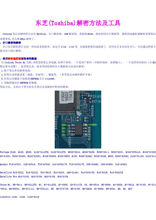
东芝(Toshiba)解密方法及工具Toshiba笔记本解密的方法有KeyDisk、并口解密狗、USB解密狗、重新刷BIOS、修改密码芯片数据等。
最新的迅驰机器解密需要售后服来算密码,有点像DELL解密了。
、并口解密狗解密并口东芝解密狗只支持一些比较老的机型,如东芝2410、1410等,直接就把密码清除掉了。
有些东芝本本没有并口,可以通过转接卡来接为并口进行解密。
、使用解密编程器读取密码数据以Toshiba Tecra M1为例,该机型的笔记本电脑,有两个密码,一个是用户密码(开机时询问,需要输入),一个是管理员密码(在BIOS 锁定部分设置)。
此类笔记本,要采用读取密码芯片数据的方法进行解密:1.取下笔记本电源和电池。
2.拆笔记本附属设备(硬盘、光驱等)、键盘等。
(参考笔记本硬件维护手册)3.在笔记本键盘下面找到EEPROM芯片24c02w8。
4.用编程器读出EEPROM的数据。
用此方法,支持以下型号的东芝笔记本电脑的开机密码解密:ortege R100, M100, M200, S100-S113TD, S100-S213TD, M205-S810, M205-S809, R200-S214, R200-S234, M400-ST9113, M400-S4032, 00-S4031, R200-S2032, R200-S2031, M405-S8003, M400-S933, M400, R205-S2062, R205-S209, M300, R200-S2062, S100-S1133, S100-S11osmio F15-AV201, G25-AV513, F25-AV205, G15-AV501-R, F15-AV201-R, G35-AV650, G35-AV600, G15-AV501atellite R15-S822, R15-S8222, R10-S613, R10-S820, A55-S1064, R10-S804TD, R15-S829, R10-S802TDatellite Pro M10-S405, M10-S406, M15-S405, M15-S406ecra M1, M3-S311, M3-S212TD, M4, M4-S115TD, M4-S335, S3-S411TD, S3, M3-S316, M3-S336, M4-S535, M4-S515, M4-S435, M4-S415 -S315, M5-S5331, M5-ST1412, M5-ST8112, M5, M3-S737TD, M5-S433, M3-S636, M4-S635, M3-S331, M3, M2, M2Vibretto U100, U105, U100-S213shiba Satellite 1100 Seriesshiba Satellite 1715 Toshiba Satellite 1715shiba Satellite 2600 Series Toshiba Satellite 2600 Series shiba Satellite 2430 Toshiba Satellite 2430shiba Satellite 1105 Series Toshiba Satellite 1105 Series shiba Satellite 1715 Toshiba Satellite 1715shiba Satellite 2610 Toshiba Satellite 2610shiba Satellite 2435 Toshiba Satellite 2435shiba Satellite 1130 Series Toshiba Satellite 1130 Series shiba Satellite 1730 Toshiba Satellite 1730shiba Satellite 2615 Toshiba Satellite 2615shiba Satellite 2715 Toshiba Satellite 2715shiba Satellite 1135 Series Toshiba Satellite 1135 Series shiba Satellite 1735 Toshiba Satellite 1735shiba Satellite 2650 Toshiba Satellite 2650shiba Satellite 2750 Toshiba Satellite 2750shiba Satellite 1605 Toshiba Satellite 1605shiba Satellite 1750 Toshiba Satellite 1750shiba Satellite 2655 Toshiba Satellite 2655shiba Satellite 2755 Toshiba Satellite 2755shiba Satellite 1625 Toshiba Satellite 1625shiba Satellite 1755 Toshiba Satellite 1755shiba Satellite 2670 Toshiba Satellite 2670shiba Satellite 2770 Toshiba Satellite 2770shiba Satellite 1675 Toshiba Satellite 1675shiba Satellite 1900 Series Toshiba Satellite 1900 Series shiba Satellite 2675 Toshiba Satellite 2675shiba Satellite 2775 Toshiba Satellite 2775shiba Satellite 1695 Toshiba Satellite 1695shiba Satellite 1905 Series Toshiba Satellite 1905 Series shiba Satellite 2695 Toshiba Satellite 2695shiba Satellite 1110 Series Toshiba Satellite 1110 Series shiba Satellite 1700 Toshiba Satellite 1700shiba Satellite 1950 Series Toshiba Satellite 1950 Series shiba Satellite 2700 Series Toshiba Satellite 2700 Series shiba Satellite 1115 Series Toshiba Satellite 1115 Series shiba Satellite 1715 Toshiba Satellite 1715shiba Satellite 1955 Series Toshiba Satellite 1955 Series shiba Satellite 2710 Toshiba Satellite 2710、短路法适用于以下机型:telitte p100,pro p100,sateliite l10,l20,l30,pro l20,satelitte m100,M200,R100,A100,tecra a6telitte M18,M30,M20,A60,PRO M10telitte 17** series,1100,1110,1130, 1200, 1900, 2430, 3000 P20,P30, P33, A30, A70, A80, M40X, M50,M60, M70, M100 cra a3,s2,a5,a6tellite a100,equium A100,satellite pro a100, atecra m7tellite A100 (PSAA2A-02C01N)CRA A4 & Satellite M40cra s1,M1详细介绍,见光盘东芝笔记本解密工具中的PDF文件。
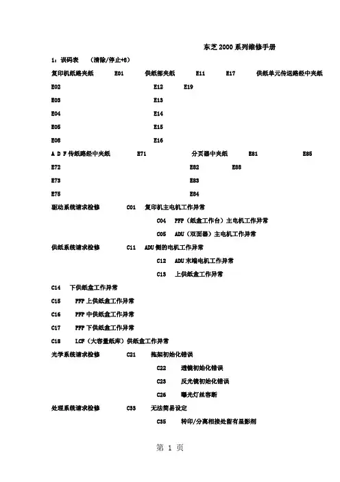
东芝2000系列维修手册1:误码表(清除/停止+8)复印机纸路夹纸 E01 供纸部夹纸 E11 E17 供纸单元传送路经中夹纸E02 E12 E19E03 E13E04 E14E05 E15E08 E16A D F传纸路经中夹纸 E71 分页器中夹纸 E81 E85E72 E82 E88E73 E83E75 E84驱动系统请求检修 C01 复印机主电机工作异常C04 PFP(纸盒工作台)主电机工作异常C05 ADU(双面器)主电机工作异常供纸系统请求检修 C11 ADU侧的电机工作异常C12 ADU末端电机工作异常C13 上供纸盒工作异常C14 下供纸盒工作异常C15 PFP上供纸盒工作异常C16 PFP中供纸盒工作异常C17 PFP下供纸盒工作异常C18 LCF(大容量纸库)供纸盒工作异常光学系统请求检修 C21 拖架初始化错误C22 透镜初始化错误C23 反光镜初始化错误C26 曝光灯丝容断处理系统请求检修 C33 无法简易设定C35 转印/分离相接处留有显影剂定影器单元 C41 开机时热敏电阻异常或加热器断路C43 预热期间或复印机已就绪时热敏电阻异常C44 预热期间或复印机已就绪时加热器断路C45 副加热器开路通讯系统请求检修 C54 分页器与主CPU通讯异常C55 ADF与主CPU通讯异常C56 PFC与主CPU通讯异常ADF请求检修 C72 定位传感器调整失灵C73 EEROM初始化错误C74 排出/保留传感器调整失灵分页器请求检修 C81 走纸电机异常C82 格升降电机异常C83 上限位错误C84 下限位错误C85 初始位置传感器异常C86 装订导条驱动电机异常C87 装订驱动电机异常C88 复印件移动传感器出错其它请求检修 C93 接收不到ADF原稿停止信号2:复印机输出信号检查(03/04)01 主电机ON 11 主电机OFF02 供纸辊离合器ON 12 供纸辊离合器OFF03 定位辊离合器ON 13 定位辊离合器OFF06 墨粉电机ON 16 墨粉电07 光风扇ON 1708 出纸风扇/ 底部风扇ON 18 出纸风扇/ 底部风扇OFF10 总计数器20 扫描电机21 透镜电机22 反光镜电机24 原稿电机30 充电输出31 转印输出32 分离输出33 曝光灯34 预转印偏压40 复印机上供纸托盘电机41 复印机上纸盒供纸辊离合器42 复印机传输离合器43 复印机下供纸托盘电机44 复印机下纸盒供纸辊离合器45 ADU制动端电机46 ADU恻面端电机47 ADU供纸辊离合器48 ADU堆纸离合器49 PFP上供纸托盘电机50 PFP上纸盒供纸辊离合器51 PFP传输离合器52 PFP中供纸托盘电机53 PFP中纸盒供纸辊离合器54 PFP下供纸托盘电机55 PFP下纸盒供纸辊离合器56 手动供纸辊离合器57 LCF托盘电机58 LCF供纸电机60 ADU电机61 PFP主电机80 DF独立老化(单面操做)81 DF独立老化(双面操做)82 DF搓纸辊转动83 DF定位辊转动84 DF传送带转动85 DF传送带转动90 分页器传送电机ON91 分页器格升降电机ON92 分页器无纸养护3:复印机调整方试(05)代码名称允许输入值初始值00 自动墨粉传感器 -------- ----01 手动曝光(100%) 0-255 128 值越大02 手动曝光(154%) 0-255 12803 手动曝光(50%) 0-255 12804 手动曝光(200%) 0-255 12805 自动曝光(100%) 0-255 12806 自动曝光(154%) 0-255 12807 自动曝光(50%) 0-255 12808 自动曝光(200%) 0-255 12809 允许曝光范围(亮) 0-255 50 值越大,10 允许曝光范围(暗) 0-255 210 值越大,14 照片曝光(100%) 0-255 157 值越大,15 照片曝光(154%) 0-255 12816 照片曝光(50%) 0-255 12817 照片曝光(200%) 0-255 12821 扫描电机速度调整 0-15 8 值加125 LED消去阵列定时调整(100%) 0-15 8 值加1后移0。
数码产品维修手册第一章:笔记本电脑维修手册 (4)1.1 笔记本电脑拆解步骤 (4)1.1.1 断开电源 (4)1.1.2 拆卸键盘和触摸板 (4)1.1.3 拆卸屏幕 (4)1.1.4 拆卸底盖 (5)1.1.5 拆卸内部组件 (5)1.2 常见故障诊断与处理 (5)1.2.1 无法开机 (5)1.2.2 黑屏 (5)1.2.3 蓝屏 (5)1.2.4 无法连接网络 (5)1.3 芯片级维修技巧 (5)1.3.1 更换南桥和北桥芯片 (6)1.3.2 更换内存芯片 (6)1.3.3 更换显卡芯片 (6)1.4 维修后的组装与调试 (6)1.4.1 组装内部组件 (6)1.4.2 组装底盖和屏幕 (6)1.4.3 连接键盘和触摸板 (6)1.4.4 调试设备 (6)第二章:智能手机维修手册 (7)2.1 智能手机拆解与组装 (7)2.2 屏幕更换与触摸屏维修 (7)2.3 电池更换与充电故障处理 (8)2.4 主板维修与常见问题解答 (8)第三章:数码相机维修手册 (9)3.1 数码相机拆解与组装 (9)3.1.1 拆解准备 (9)3.1.2 拆解步骤 (9)3.1.3 组装步骤 (9)3.2 镜头更换与维护 (9)3.2.1 镜头更换 (9)3.2.2 镜头维护 (9)3.3 传感器维修与故障处理 (9)3.3.1 传感器故障处理 (9)3.3.2 传感器维修 (10)3.4 闪光灯与电池维修技巧 (10)3.4.1 闪光灯维修 (10)3.4.2 电池维修 (10)第四章:平板电脑维修手册 (10)4.1.1 准备工作 (10)4.1.2 拆解步骤 (10)4.1.3 组装步骤 (10)4.2 屏幕更换与触摸屏维修 (11)4.2.1 屏幕更换 (11)4.2.2 触摸屏维修 (11)4.3 主板维修与故障处理 (11)4.3.1 主板维修 (11)4.3.2 故障处理 (11)4.4 电池更换与充电问题解决 (11)4.4.1 电池更换 (11)4.4.2 充电问题解决 (11)第五章:家用音响设备维修手册 (12)5.1 音响设备拆解与组装 (12)5.1.1 拆解步骤 (12)5.1.2 组装步骤 (12)5.2 音箱单元更换与调试 (12)5.2.1 更换步骤 (12)5.2.2 调试方法 (12)5.3 放大器维修与故障处理 (12)5.3.1 常见故障 (13)5.3.2 维修方法 (13)5.4 电源与线材问题解决 (13)5.4.1 电源问题 (13)5.4.2 线材问题 (13)第六章:数码打印机维修手册 (13)6.1 打印机拆解与组装 (13)6.1.1 拆解准备 (13)6.1.2 拆解步骤 (13)6.1.3 组装步骤 (14)6.2 喷头清洗与更换 (14)6.2.1 喷头清洗 (14)6.2.2 喷头更换 (14)6.3 电路板维修与故障处理 (14)6.3.1 电路板检查 (14)6.3.2 电路板维修 (14)6.3.3 故障处理 (14)6.4 走纸系统维护与调整 (15)6.4.1 走纸系统检查 (15)6.4.2 走纸系统维护 (15)6.4.3 走纸系统调整 (15)第七章:路由器与调制解调器维修手册 (15)7.1 设备拆解与组装 (15)7.1.2 拆解步骤 (15)7.1.3 组装步骤 (15)7.2 电路板维修与故障处理 (16)7.2.1 电路板检查 (16)7.2.2 故障处理 (16)7.3 无线信号优化与调试 (16)7.3.1 无线信号优化 (16)7.3.2 无线信号调试 (16)7.4 软件升级与恢复出厂设置 (16)7.4.1 软件升级 (16)7.4.2 恢复出厂设置 (16)第八章:MP3、录音笔维修手册 (17)8.1 设备拆解与组装 (17)8.1.1 拆解准备 (17)8.1.2 拆解步骤 (17)8.1.3 组装步骤 (17)8.2 电路板维修与故障处理 (17)8.2.1 电路板故障分类 (17)8.2.2 故障处理方法 (17)8.3 电池更换与充电问题解决 (17)8.3.1 电池更换方法 (17)8.3.2 充电问题解决 (18)8.4 音质优化与调试 (18)8.4.1 音质优化方法 (18)8.4.2 调试步骤 (18)第九章:电子手表维修手册 (18)9.1 手表拆解与组装 (18)9.1.1 拆解工具准备 (18)9.1.2 拆解步骤 (18)9.1.3 组装步骤 (19)9.2 表盘更换与维护 (19)9.2.1 表盘更换 (19)9.2.2 表盘维护 (19)9.3 电路板维修与故障处理 (19)9.3.1 电路板维修 (19)9.3.2 故障处理 (19)9.4 电池更换与防水处理 (19)9.4.1 电池更换 (20)9.4.2 防水处理 (20)第十章:键盘与鼠标维修手册 (20)10.1 设备拆解与组装 (20)10.1.1 拆解工具准备 (20)10.1.2 拆解步骤 (20)10.2 键盘按键更换与故障处理 (20)10.2.1 按键更换步骤 (20)10.2.2 故障处理 (21)10.3 鼠标传感器更换与调试 (21)10.3.1 传感器更换步骤 (21)10.3.2 调试 (21)10.4 线材与接口问题解决 (21)10.4.1 线材问题 (21)10.4.2 接口问题 (21)第十一章:耳机与麦克风维修手册 (21)11.1 设备拆解与组装 (21)11.2 耳机单元更换与调试 (22)11.3 麦克风维修与故障处理 (22)11.4 线材与接口问题解决 (23)第十二章:其他数码产品维修手册 (23)12.1 游戏机维修 (23)12.1.1 故障诊断 (23)12.1.2 维修方法 (23)12.2 电子书阅读器维修 (23)12.2.1 故障诊断 (23)12.2.2 维修方法 (24)12.3 智能穿戴设备维修 (24)12.3.1 故障诊断 (24)12.3.2 维修方法 (24)12.4 数码配件维修与保养 (24)12.4.1 维修 (24)12.4.2 保养 (25)第一章:笔记本电脑维修手册1.1 笔记本电脑拆解步骤笔记本电脑的拆解是进行维修的第一步,正确的拆解步骤可以保证维修过程的顺利进行,同时避免对设备造成不必要的损坏。
笔记本维修手册本手册旨在为用户提供笔记本维修的基本知识和技巧,以帮助他们解决笔记本常见的故障和问题。
请在维修前先确保您已经仔细阅读并理解以下内容,并按照正确的步骤进行操作。
1. 前言笔记本电脑作为一种移动性强、方便携带的电子设备,已经成为大众生活中不可或缺的一部分。
然而,由于使用过程中的摔落、碰撞、水浸等不可预料的意外事件,这些常见问题可能会导致笔记本电脑出现各种故障。
通过本手册,您将学习如何识别和解决这些问题,为您的笔记本电脑维修提供参考。
2. 常见故障2.1 电池问题电池是笔记本电脑的重要组成部分,常见的问题包括电池无法充电、电池寿命短等。
在这一节中,我们将介绍如何检测和更换笔记本电脑的电池。
2.2 显示屏问题显示屏故障可能导致无图像显示、模糊或闪烁的情况。
我们将指导您如何检查屏幕连接和更换显示屏。
2.3 键盘问题键盘是常见的故障点,可能会造成按键无反应、按键粘连等问题。
这一节将告诉您如何解决这些问题以及如何更换键盘。
2.4 硬盘问题硬盘是储存数据的重要组件,出现的问题可能包括启动失败、数据丢失等。
我们将介绍如何进行硬盘故障排查和恢复数据。
2.5 散热问题过热可能会导致笔记本电脑性能下降、意外关机等问题。
本节中,您将学习如何清洁散热器和风扇,以及如何更换散热器。
3. 维修工具在进行笔记本维修之前,您需要准备一些基本的维修工具。
这些工具包括螺丝刀、钳子、吸尘器等。
了解正确使用这些工具的方法,可以帮助您更好地进行维修操作。
4. 维修步骤在这一节中,我们将针对不同的常见问题和故障,逐步介绍维修步骤和操作技巧。
请确保在进行维修操作之前,先确认设备已经断电,并将其放置在平稳的工作台上。
5. 注意事项维修笔记本电脑需要一定的技术和专业知识。
在进行维修操作之前,请务必参考厂商提供的手册或相关指南,并遵循正确的操作步骤。
如果您不确定自己的维修能力,建议寻求专业技术支持。
6. 总结本手册基于常见的笔记本电脑故障场景,提供了相应的维修指南。
东芝系列维修手册第一章:介绍1.1 使用目的1.2 范围和适用性1.3 术语和缩写第二章:产品概述2.1 产品特点2.2 硬件规格2.3 软件规格2.4 外观设计2.5 附件列表第三章:维修流程3.1 常见故障诊断3.2 维修所需工具3.3 打开设备3.4 组件拆卸和更换3.5 组件固定和连接3.6 维修完成测试第四章:维护与保养4.1 清洁指南4.2 电源管理4.3 防尘处理4.4 温度和湿度要求4.5 停电和断电保护第五章:常见问题解决方案5.1 无法启动设备5.2 屏幕显示问题5.3 声音问题5.4 网络连接问题5.5 外部设备无法识别5.6 其他常见问题第六章:故障代码和解决办法6.1 硬件故障代码6.2 软件故障代码6.3 解决办法和故障排除步骤第七章:维修记录与保修7.1 维修记录表格7.2 保修政策和流程7.3 延长保修计划第八章:维修安全与注意事项8.1 电源安全8.2 维修过程中的安全注意事项8.3 设备维护与保养注意事项8.4 废弃设备处理第九章:常见维修工具使用说明9.1 螺丝刀9.2 钳子9.3 测量工具9.4 探头和夹子9.5 清洁工具第十章:常见故障案例及处理方法10.1 故障现象描述10.2 故障原因分析10.3 解决措施和步骤结论本手册详细介绍了东芝系列产品的维修流程、维护与保养方法以及常见故障解决方案。
通过学习本手册,用户可以更好地了解设备的内部构造和工作原理,更加准确地定位和解决常见故障。
另外,本手册还对常见维修工具的使用方法进行了说明,并提供了一些常见故障案例,帮助用户更好地理解维修过程中的注意事项和操作技巧。
在维修过程中,务必遵循安全操作规范,并注意电源安全和个人安全。
同时,定期进行设备的维护与保养工作,可以延长设备的使用寿命和保持正常的工作状态。
本手册是一本实用的指导手册,适用于东芝系列产品的用户和维修人员。
无论您是初学者还是有一定维修经验的专业人士,本手册都有一定的参考价值。
电脑维修指导手册目录第一部分总则第一章电脑维修的基本原则和方法第二章电脑维修步骤与维修操作注意事项第二部分常见故障判断第一章加电类故障第二章启动与关闭类故障第三章磁盘类故障第四章显示类故障第五章安装类故障第六章操作与应用类故障第七章局域网类故障第八章Internet类故障第九章端口与外设故障第十章音视频类故障第十一章兼容类故障第三部分附录附录一故障处理流程之一加电类故障处理流程之二启动与关闭类故障处理流程之三磁盘类故障处理流程之四显示类故障处理流程之五安装类故障处理流程之七局域网类故障处理流程之八Internet类故障处理流程之九端口与外设故障处理流程之十音视频类故障处理流程附录二部分部件、设备的技术规格之一内存技术规格识别之二显示器技术规格之三Windows 98SE关机问题前言本手册共分三大部分。
第一部分阐述了维修的一般方法,维修的原则及维修中应注意的问题。
这一部分是整个手册的关键部分,只有理解并掌握其中的观点、方法后,才可能理解和应用第二部分的内容。
第二部分从故障现象入手,通过对故障现象分类,进而对每一类故障的分析、判断提供一种思路或方法。
附录一中的故障判断流程是对相关故障类的补充,试图对刚从事维修工作的工程师提出一个入手的方法。
最后一部分是附录。
在附录中除故障判断流程外,还包含一些部件的技术规格和标准,以便工程师在维修中参考。
第一部分总则本部分主要介绍维修的基本原则、方法,和维修的过程、在维修中应注意的问题。
在最后,为了能方便地使用第二部分的内容,提供了基本的维修判断的思路。
第一章电脑维修的基本原则和方法电话判断的基本原则和方法上门服务前的准备电话判断准备备件这里所述原则、方法等是第二部分分类判断的基础,需要认真遵守执行。
§1.1 进行电脑维修应遵循的基本原则:一、进行维修判断须从最简单的事情做起简单的事情,一方面指观察,另一方面是指简捷的环境。
简单的事情就是观察,它包括:1、电脑周围的环境情况——位置、电源、连接、其它设备、温度与湿度等;2、电脑所表现的现象、显示的内容,及它们与正常情况下的异同;3、电脑内部的环境情况——灰尘、连接、器件的颜色、部件的形状、指示灯的状态等;4、电脑的软硬件配置——安装了何种硬件,资源的使用情况;使用的是使种操作系统,其上又安装了何种应用软件;硬件的设置驱动程序版本等。
FIELD REPLACEABLE UNIT DOCUMENTATIONTecra TMnot connected to the unit and the environment in which you are working on is protected fromElectro-Static Discharge(ESD).A1 SeriesBATTERY PACK REMOVAL1. Turn the computer upside down as shown.2. Slide the battery release lever in the direction of the arrow.3. Lift out the battery pack assy .HDD REMOVAL1. Turn the computer upside down.2. Remove two M2.5x16 black flat head screws securing HDD slot cover and pull out the cover ..4. Separate the battery pack from the battery cover.OPTIONAL PC CARD REMOVAL 1. Press the eject button of the PC Card you want to remove.2. Press the extended eject button to pop the PC card out slightly.3. Grasp the PC Card and pull it outNOTE: Before removing any PCMCIA device, make sure it is “STOPPED” in the PC Card Manager.Battery packBattery cover A1 Series6. Remove four M3x4 brass flat head screws securing the HDD bracket to the drive.4. Slowly spread out the memory clips and pull the memory module out of the connector on a 45 degree angle.3. Remove one M2.5x5 black flat head screw securing the HDD assembly.4. Grasp the HDD bracket handle and pull to disconnect the HDD assembly.5. Lift the HDD assembly out of the HDD bay.MEMORY MODULE REMOVAL1. Turn the computer upside down.2. Remove one M2.5x4 black flat head screwsecuring the memory cover.3. Lift out thecover .M2.5x5 black flat head screwHDD assyHDD bracket handleM3x4 brass flat head screwsM2.5x4 black flat head screwMemory moduleMemory clipsA1 SeriesWIRELESS LAN CARD REMOVAL1. Turn the computer upside down.2. Remove one M2.5x4 black flat head screw securing the Mini PCI slot cover.3. Lift out the PCI slot cover .4. Peel off the glass tape securing the mini coax cables.5. Disconnect the white mini coax cable from main connector and the black mini coax cable from aux connector.6. Gently press out the Mini PCI slot clips and pull the Mini PCI card out of the connector on a 30 degree angle.MODEM BOARD REMOVAL1. Remove one M2.5x4 black flat head screw securing the modem slot cover.2. Insert your finger nail or the case separator into the notched side of the cover and lift up to release the latch securing the modem slot cover.3. Remove two M2x4 black screws securing the modem board.4. Gently lift up the modem board to disconnect it fromthe system board and disconnect the MJ harnessfrom JP1 on the modem board.Mini PCI cardPCI clipsWhite mini coax cableBlack mini coax cableModem slot cover M2.5x4 black flat head screws ModemMJ Harness M1 Series1. Turn the computer upside down.2. Remove two M2.5x5 black flat head screws and one M2.5x16 black flat head screw securing the modem cover.3. Remove the modem cover .COOLING MODULE REMOVALCOOLING MODULE REMOVAL1. Disconnect the fan cable from PJ8770 on the system board.2. Remove two M2.5x5 black flat head screws securing the fan.3. Lift out thefan ..2. Lift out the CPU .M2.5x5 black flat head screwsCooling module brace Cooling module1. Remove M2x6 brass screws securing the cooling module brace.2. Lift out the cooling module brace .3. Lift out the cooling module .CPUClose PJ8770FanFan cableA1 Series1. Open the display panel.2. Using the case separator, unlatch the keyboard holder as shown above.KEYBOARD REMOVAL3. Remove two M2.5x2.8 black flat head screws securing the keyboard.4. Remove one M2.5x2.8 black flat head screw securing the keyboard holder plate.5. Lift out the keyboard holder plate .6. Lift out the keyboard and set it on the palm rest.7. Remove one M2.5x8 black flat head screw securing the keyboard support plate.8. Lift out the keyboard support plate .KEYBOARD REMOVALKeyboard9. Lay the keyboard as shown above.10. Disconnect the keyboard cable from PJ3200 on the system board.11. Lift out the keyboard .Keyboard holderKeyboard holderplateM2.5x4 black flat head screwM2.5x8 black flat head screwKeyboard support plateKeyboard cableA1 SeriesCD-R/W/DVD-ROM DRIVE REMOVAL1. Turn the computer upside down.2. Remove one M2.5x5 black flat head screw securing the CD-R/W/DVD-ROM drive.drive bay.5. Remove two M2x1.7 brass screws securing the CD-R/W/DVD-ROM drive bracket and lift out the bracket6. Remove one M2x3 silver screw securing the side bracket and lift out the bracket.CD-R/W/DVD-ROM drive CD-R/W/DVD-ROM DRIVE REMOVAL1. Turn the computer upside down and remove the following twenty screws:- 7 M2.5x5 black flat head screws - 13 M2.5x16 black flat head screwsCD-R/W/DVD-ROM driveM2.5x5 black flat head screw M2x1.7 brass screwsM2x3 silver screwSide bracketCD-RW/DVD drive bracketM2.5x16 black flat head screwsA1 SeriesTOP COVER REMOVAL1. Disconnect the LCD/FL cable from PJ5600 on the system board.2. Lift up the plastic insulator covering the Left/Right speaker cables and disconnect the Left/Rightspeaker cables from PJ6000/PJ6001.3. Remove one M2.5x8 black flat head screw securing top cover and lift out the top cover assembly.TOUCH PAD ASSEMBL Y REMOVAL1. Disconnect the touch pad cable from PJ3201 on the system board.2. Remove one M2.5x5 black flat head screwsecuring the touch pad assembly.3. Lift out the touch pad assembly .PJ2004Touch pad assemblycableBAT CON HOLDER REMOVAL 1. Remove two M2.5x8 black flat head screw securing the bat con holder.2. Lift out the bat con holder from the system board.M2.5x8 black flat head screwsSYSTEM BOARD REMOVAL1. Peel off the glass tape securing the RTC battery cable.2. Remove two M2.5x5 black flat head screw securing the system board.3. Lift up the system boardfrom the right hand sideand lift it out.A1 SeriesDC-IN JACK/RTC BATTERY REMOVAL1. Peel off the glass tape securing the DC-In jack/ RTC battery harness.2. Disconnect the DC-In jack harness from PJ8800 on the system board.3. Disconnect the RTC battery harness fromPJ8790 on the system board .RTC battery harnessDC-InJack harnessPJ8800Glass tapeA1 SeriesFL INVERTER AND 14” LCD REMOV ALFIELD REPLACEABLE UNIT DOCUMENTATIONTOSHIBATough Enough for Today’s World14” DISPLAY MASK REMOVAL1. Removedisplay assembly using a pair of fine-tipped tweezers.2. Remove two M2.5x6 black flat head screws securing the display mask.3. There are 24 latches securing the display mask .Carefully insert your fingers between the mask and the LCD panel and pry open the latches starting from the bottom six latches , to the five latches on the right andleft sides , ending with the six top latches .1. Remove one M2x4 brass flat head screwsecuring the FL inverter board.2. Carefully lift up the FL inverter board anddisconnect the LCD /FL cable from CN1 and the FL cable from CN2..3. Remove four mask seals to expose four screws securing the LCD module assembly.4. Remove four M2X4 brass flat head screws securing the LCD module assembly.5. Carefully rotate out the top of the LCD module enough to access the display cable.6. Peel off the tape securing the LCD/FL cable and disconnect the cable.7. Remove four M2x3 silver flat head screws securing the left/right LCD brackets.LatchTecra TMA1 Series。