Trinamic应用笔记-PWM斩波技术spreadCycle
- 格式:pdf
- 大小:606.02 KB
- 文档页数:12
!-PWM的工作原理脉宽调制 PWM 是开关型稳压电源中的术语。
这是按稳压的控制方式分类的,除了 PWM 型,还有 PFM 型和 PWM 、PFM 混合型。
脉宽宽度调制式( PWM )开关型稳压电路是在控制电路输出频率不变的情况下,通过电压反馈调整其占空比,从而达到稳定输出电压的目的。
随着电子技术的发展,出现了多种 PWM 技术,其中包括:相电压控制 PWM 、脉宽 PWM 法、随机 PWM 、SPWM 法、线电压控制PWM 等,而在镍氢电池智能充电器中采用的脉宽 PWM 法,它是把每一脉冲宽度均相等的脉冲列作为 PWM 波形,通过改变脉冲列的周期可以调频,改变脉冲的宽度或占空比可以调压,采用适当控制方法即可使电压与频率协调变化。
可以通过调整 PWM 的周期、 PWM 的占空比而达到控制充电电流的目的。
pwm的定义脉宽调制 (PWM) 是利用微处理器的数字输出来对模拟电路进行控制的一种非常有效的技术,广泛应用在从测量、通信到功率控制与变换的许多领域中。
模拟信号的值可以连续变化,其时间和幅度的分辨率都没有限制。
9V 电池就是一种模拟器件,因为它的输出电压并不精确地等于9V ,而是随时间发生变化,并可取任何实数值。
与此类似,从电池吸收的电流也不限定在一组可能的取值范围之内。
模拟信号与数字信号的区别在于后者的取值通常只能属于预先确定的可能取值集合之内,例如在 {0V, 5V} 这一集合中取值。
模拟电压和电流可直接用来进行控制,如对汽车收音机的音量进行控制。
在简单的模拟收音机中,音量旋钮被连接到一个可变电阻。
拧动旋钮时,电阻值变大或变小;流经这个电阻的电流也随之增加或减少,从而改变了驱动扬声器的电流值,使音量相应变大或变小。
与收音机一样,模拟电路的输出与输入成线性比例。
尽管模拟控制看起来可能直观而简单,但它并不总是非常经济或可行的。
其中一点就是,模拟电路容易随时间漂移,因而难以调节。
能够解决这个问题的精密模拟电路可能非常庞大、笨重 ( 如老式的家庭立体声设备 ) 和昂贵。

选型手册 2019集成电路我们将数字信号转化为物理运动关于我们拥有数以十年构筑高可靠性嵌入式构架的行业经验Trinamic 是一家在嵌入式电机运动控制领域的全球领导企业。
我们的芯片和微控制系统将数字信号和现实物理世界联系在一起。
我们的工程师是解决现实世界问题的专家, 他们几十年的经验体现在我们的每一个产品中。
Trinamic代表了精密、可靠和高效。
2 Trinamic 选型手册电动机是日常生活中必不可少的一部分,近年来,这些设备的使用量持续上升。
中产阶级的不断壮大,加上家庭自动化程度的提高,以及家庭周围电动马达驱动的产品数量的增加,是经济增长的主要动力”使用TRINAMIC技术来提升您的产品品质人类生活环境对自动化不断增加的需求趋势导致了控制运动系统的爆炸式增长。
产品开发人员必须处理日益复杂的系统,而且很难成为所有领域的专家。
Trinamic通过一种基于API的方法解决了这一问题,帮住用户缩短其产品上市时间,节约了成本,并最终提高产品性能。
Trinamic产品服务于多个市场,包括实验室自动化,工厂自动化,半导体设备,纺织设备,机器人,金融设备......等对可靠性要求比较高的场合。
Bryan Turnbough, IHS分析师。
我们最新的产品为高速增长的新兴市场,如3D打印,医疗泵和自动化移液提升了新的性能标准。
为什么世界上最具前瞻性的公司一再选择Trinamic?诚然, 有些人选择我们是因为我们的产品性能优越。
然而,我们的大多数客户选择我们,是因为我们对运动控制的专注 为用户提供了深入的应用知识,并使我们的客户能够在他们的特定领域更快地创新。
Trinamic 选型手册 3Trinamic带来的创新TRINAMIC是一家具有20多年运动控制芯片、模块和机电驱动设计和营销经验的创新型公司。
在其历史上,TRINAMIC工程师获得了许多专利,包括无传感器电机负载检测和自动混合衰减步进电机无传感器力矩测量。
PWM交流斩控技术的交流稳压电源总体设计1 PWM交流斩控技术概述1.1 PWM控制的基本原理PWM (Pulse Width Modulation)控制就是脉宽调制技术:即通过对一系列脉冲的宽度进行调制,来等效的获得所需要的波形(含形状和幅值)。
PWM控制技术以面积等效原理为基础。
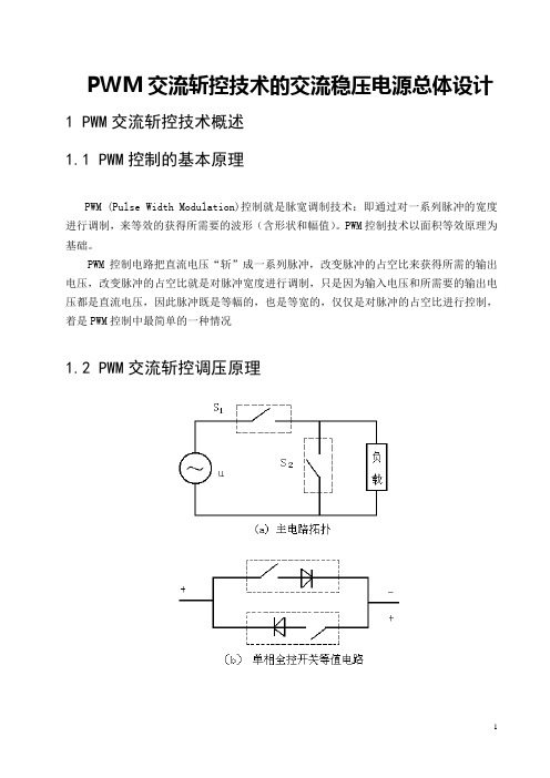
PWM控制电路把直流电压“斩”成一系列脉冲,改变脉冲的占空比来获得所需的输出电压,改变脉冲的占空比就是对脉冲宽度进行调制,只是因为输入电压和所需要的输出电压都是直流电压,因此脉冲既是等幅的,也是等宽的,仅仅是对脉冲的占空比进行控制,着是PWM控制中最简单的一种情况1.2 PWM交流斩控调压原理图1-1图1-1(a )所示,假定电路中各部分都是理想状态。
开关S 1为斩波开关,S 2为考虑负载电感续流的开关,二者均为全控开关器件与二极管串联组成的单相开关[见图1-1(b )]。
S 1及S 2不允许同时导通,通常二者在开关时序上互补。
定义输入电源电压u 的周期T 与开关周期Ts 之比为电路工作载波比Kc ,(Kc=T/Ts )。
图1-1(c )表示主电路在稳态运行时的输出电压波形。
显然输出电压u o 为:断开导通,断开导通,12210)(S S S S uu t E u o ⎩⎨⎧== (1)式中:E (t )为开关函数,其波形示于图1-1(c ),函数由式(2)定义。
断开导通,断开导通,122101)(S S S S t E ⎩⎨⎧= (2)在图1-1(a )电路条件下,则t U t E u o ωsin 2)(= (3)E (t )函数经傅立叶级数展开,可得∑∞=-+=1)cos(sin 2)(n n s nn n D t E θωθπ (4) 式中:D=t on1/Ts ,ωs =2π/Ts ,θn =n π/Ts ;D 为S 1的占空比;t on1为一个开关周期中S 1的导通时间。
将式(4)代入式(3)可得:]})sin[(]){sin[(sin 21sin 21n s n s n no t n t n nU t U D u θωωθωωθπω----++=∑∞- (5) 式(5)表明,u o 含有基波及各次谐波。
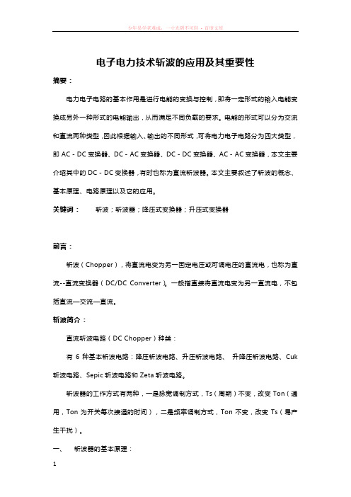
电子电力技术斩波的应用及其重要性摘要:电力电子电路的基本作用是进行电能的变换与控制,即将一定形式的输入电能变换成另外一种形式的电能输出,从而满足不同负载的要求。
电能的形式可以分为交流和直流两种类型,因此根据输入、输出的不同形式,可将电力电子电路分为四大类型,即AC-DC变换器、DC-AC变换器、DC-DC变换器、AC-AC变换器,本文主要介绍其中的DC-DC变换器,有时也称为直流斩波器。
本文主要叙述了斩波的概念、基本原理、电路原理以及它的应用。
关键词:斩波;斩波器;降压式变换器;升压式变换器前言:斩波(Chopper),将直流电变为另一固定电压或可调电压的直流电,也称为直流--直流变换器(DC/DC Converter)。
一般指直接将直流电变为另一直流电,不包括直流—交流—直流。
斩波简介:直流斩波电路(DC Chopper)种类:有6种基本斩波电路:降压斩波电路、升压斩波电路、升降压斩波电路、Cuk 斩波电路、Sepic斩波电路和Zeta斩波电路。
斩波器的工作方式有两种,一是脉宽调制方式,Ts(周期)不变,改变Ton(通用,Ton为开关每次接通的时间),二是频率调制方式,Ton不变,改变Ts(易产生干扰)。
一、斩波器的基本原理:直流斩波器乃利用功率组件对固定电压之电源做适当之切割以达成负载端电压改变之目的。
若其输出电压较输入之电源电压低,则称为降压式(Buck )直流斩波器,若其输出电压较输入之电源电压高,则称为升压式(Boost)直流斩波器;当直流斩波器导通(Ton)时,负载端之电压Vo等于电源电压Vs,当直流斩波器截止(Toff)时,负载端之电压Vo为0,如此适当的控制直流斩波器可使直流电源断续的出现在负载测,只要控制直流斩波器的导通时间,即可改变负载的平均电压。
由图1.1(b)可看出输出电压之峰值等于电源电压Vs,而输出电压之平均值Vo随Ton之时间而变。
而最常见之改变方式为 1.周期T固定,导通时间Ton改变,称脉波宽度调变。

斩波技术原理
斩波技术是一种将直流电转换为另一固定电压或可调电压的直流电的技术,也称为直流-直流变换器(DC/DC Converter)。
其工作原理主要是通过脉宽调制(PWM)或频率调制等方式,将直流电源“斩”成一系列的脉冲,再通过滤波电路将脉冲平均化,从而得到所需的直流电压。
斩波电路可以分为降压斩波电路、升压斩波电路和升降压斩波电路等。
斩波电路可以用于调节直流电压,广泛应用于各种电源供应系统和电机控制系统等领域。
斩波电路的工作原理可以分为以下几个步骤:
1. 调整脉冲宽度:通过控制斩波器开关的开通时间和关断时间,可以调整输出脉冲的宽度,从而得到所需的直流电压。
2. 滤波平滑:斩波器输出的脉冲电流经过滤波电路,将脉冲平均化,得到平滑的直流电流。
3. 反馈控制:斩波器可以通过反馈控制电路,根据输出电压的大小自动调整开关的开通时间和关断时间,实现输出电压的自动调节。
斩波技术的应用非常广泛,例如在电动车充电器、可调直流电源、LED照明电源等领域都有应用。
单片机控制的PWM斩波式交流净化稳压电源摘要: 介绍了传统的正弦能量分配交流净化稳压电源的基本原理及如何用高频斩波和单片机技术对其进行改造。
关键词: 高频斩波交流稳压器 AVR目前,在各种交流稳压电源中,采用正弦能量分配技术的交流净化稳压电源是一种技术先进的稳压电源。
这种电源主要是通过改变晶闸管的触发角θ,来控制调感支路的等效电感,从而起到稳定输出电压的作用。
它具有性价比高、可靠性好等特点。
但是这种方式产生的谐波较多,电感损耗较大,噪音明显,尤其对电网产生很大干扰。
为此,笔者用高频PWM斩波技术对其进行改造,用MOSFET或IGBT代替TRIAC,通过调节高频交流斩波器的脉冲宽度来调节等效电感。
较好地解决了上述问题。
传统的正弦波交流净化电源原理。
图1中T是带气隙的自耦变压器,输入交流电接T的B点,由C点输出稳定的交流电压。
L、L1和L2是线性电感器,L和双向晶闸管V组成调感支路。
L1和C1组成3次谐波滤波器,L2和C2组成5次谐波滤波器,减小输出电压的失真度。
采用脉冲相位控制技术改变双向晶闸管V的导通角,从而调整L的等效电感值,从T的N2绕组取得补偿电压,达到稳压目的。
用高频斩波技术改造传统的正弦波交流净化电源的关键是用高频交流开关取代双向晶闸管。
高频交流开关有两种形式:整流桥+IGBT式和MOSFET反串联式,。
整流桥+IGBT式适合于大功率电源,MOSFET反串联式适合于中小功率电源。
下面具体介绍以整流桥+IGBT为交流功率开关、AVR系列单片机90S8535为控制核心的单片机控制高频斩波调感式交流稳压电源。
其原理框图。
由于是感性负载,又不能像直流斩波那样加续流回路,所以要给IGBT加开通和关断缓冲电路。
高频交流开关控制采用了EPWM直流等电位调制技术。
为使波形半波奇对称和四分之一偶对称,以消除傅里叶级数中的余弦项和偶次谐波,为三角波频率,fs为市电工频;为脉冲宽度,为输出电压的偏差,三角波电压的方程式为:输出电压偏差ΔU为采样电压,触发脉冲起点和终点的方程式为:各触发脉冲的起点角和终点角的数值为:由于PWM斩波波形是镜对称和原点对称,因此它的傅里叶级数中将只包含正弦项中的奇次谐波,即:由上式可知,N越大谐波频率越高。
自举电容大小斩波pwm频率
自举电容大小以及斩波PWM频率在电气工程中都是非常重要的
参数。
让我先从自举电容大小开始回答你的问题。
自举电容是指用于驱动MOSFET的高侧驱动器电路中的一个电容。
它的作用是在MOSFET导通时提供所需的电荷,以确保MOSFET能够
正确导通。
自举电容的大小通常取决于电路中的电流要求、开关频
率以及所需的电压稳定性。
一般来说,自举电容的大小越大,能够
提供的电荷就越多,从而可以支持更大的电流。
然而,过大的自举
电容也会增加成本和电路的体积,因此需要在设计中进行权衡。
接下来是关于斩波PWM频率的回答。
斩波PWM(Pulse Width Modulation)是一种常用的调节技术,用于控制电路中的开关元件(比如MOSFET或IGBT)的导通时间,
从而控制输出电压或电流。
斩波PWM频率指的是开关元件每秒钟开
关的次数,通常以赫兹(Hz)为单位。
斩波PWM频率的选择受到多
种因素的影响,包括电路中的电感和电容值、所需的控制精度、以
及开关元件的特性等。
一般来说,较高的斩波PWM频率可以提供更平滑的输出电压波形,减小输出滤波器的尺寸和成本。
然而,较高的频率也会增加开关损耗,并可能导致EMI(电磁干扰)问题。
因此,在选择斩波PWM 频率时需要综合考虑上述因素,并进行合适的权衡。
综上所述,自举电容大小和斩波PWM频率都是电路设计中需要仔细考虑和优化的参数,它们直接影响着电路的性能和稳定性。
在实际设计中,需要根据具体的应用需求和性能要求来选择合适的自举电容大小和斩波PWM频率。
基于PWM技术的新型高效率直流斩波器基于PWM技术的新型高效率直流斩波器摘要:本系统以Buck降压,Boost升压斩波电路为核心设计新型高效率直流斩波器。
通过STM32检测显示输出电流,以及对电路的过充保护。
采用TL494产生频率为150kHz的PWM波形,进行闭环反馈控制,从而实现稳压输出电流可调。
实验结果表明:充电模式时,电源输入的直流电压在比较宽的范围内变化时,电源输出直流电压能够保持较高的稳定性且变化率不大于1%。
电流可进行线性步进,控制精度为0.05%,效率达到91%以上。
放电模式时,输出电压恒定,变换器效率可达96%。
本电路能够自动转换工作模式,且重量在500g 以内。
【关键词】Buck电路Boost电路TL494 STM32分布式电源系统应用的普及推广以及电池供电移动式电子设备的飞速发展,其电源系统需用的直流斩波模块越来越多,对其性能要求越来越高。
除去常规电性能指标以外,对其体积要求越来越小,也就是对其功率密度的要求越来越高,对转换效率要求也越来越高,也即发热越来越少。
这样其平均无故障工作时间才越来越长,可靠性越来越好。
因此如何开发设计出更高功率密度、更高转换效率、更低成本更高性能的直流斩波器始终是近二十年来电力电子技术工程师追求的目标。
本品将提供一种新型的更加高效的直流斩波器。
1 系统方案1.1 双向直流斩波模块的比较与选择方案一:双向同步整流电路该方案从左向右是Buck降压充电电路,从右向左是Boost升压放电电路,结构简单,所用元器件少,输出纹波电压小。
整个电路体积小、重量轻,转换效率高且输出稳定。
对元器件参数要求严格,容易实现对电路的整体控制如图1。
方案二:Buck降压,Boost升压型电路该方案将直流电压通过Buck型拓扑结构进行降压变换,然后采用Boost型拓扑结构进行升压变换。
电路原理简单易懂,但所用元器件过多,且Buck型变换器驱动电路和控制电路的电源方案较麻烦,可靠性不高,如图2、图3。
POWER DRIVER FOR STEPPER MOTORSParameterization of spreadCycle™Table of contents1 Optimizing Chopper Settings (1)1.1 Motor Settings (1)2 Qualitative Approach for a Two Phase Stepper (2)2.1 Preparations (2)2.2 Low and Medium Velocity Optimization (3)2.3 Using Hysteresis Decrement (5)2.4 Stand Still Optimization (6)2.5 High Velocity Optimization (7)3 Optimizing Chopper Settings for Classic Chopper Operation (9)4 Qualitative Approach to Optimize Chopper Settings for a Three Phase Stepper (10)4.1 Preparations (10)4.2 Low and Medium Velocity Optimization (11)4.3 High Velocity Optimization (11)5 Revision History (12)5.1 Document Revision (12)1 Optimizing Chopper SettingsChopper settings can easily be optimized by watching the motor axis behavior and feeling motor vibration with your finger tips, and by optionally measuring the motor current with an oscilloscope. The following description shall give a guideline to come to good chopper settings for your application with a minimum time-effort.1.1 Motor SettingsAs a first step, you should understand which parameters have a direct or indirect influence on the chopper settings, and thus should be selected before starting optimization.Table 1 Parameters which should be considered before optimizing chopper settings2Qualitative Approach for a Two Phase StepperWe will optimize motor settings for the required velocities sequentially; however one or more iterations might be taken in case a single set of settings is desired.2.1PreparationsTake your motor into operation at nominal conditions. Attach an oscilloscope with current probe to one of the motor coils, if possible. You might measure the coil voltage to assess the chopper frequency. In case you have access to the sense resistors, measure the voltage over one or both sense resistors. This way, you do not need a current probe.1.Select proper hardware settings like blank time TBL.Hint: A too low TBL will lead to distorted sine waves, but the value should not be unnecessarily high. 1-2µs (TBL= 1 or 2 at 16MHz clock frequency) is a good starting point.2.Switch on spreadCycle chopper mode (chm=0)in the range of 5µs to 20µs3.Choose an off-time setting tOFF4.Choose a hysteresis end value of 5 to 12, e.g. 10, and write it to HEND(HSTART=0, HEND=13).Remember, that HEND uses an offset of -3, HSTART uses an offset of +1.2.2Low and Medium Velocity OptimizationIn the low and medium velocity range, the motor is to work with equidistant steps, lowest possible vibration, and low chopper noise. Use highest possible microstep resolution for your tests.Operate your motor at a medium velocity. Try feeling motor vibrations at different velocities with your fingertips. Try seeing and feeling microstep equidistance at very low velocities.Hint: A long pointer attached to the motor axis will help checking microstep performance at lowest velocity.You might want to check the current waveform using an oscilloscope. The oscilloscope should show a pure sine wave as shown in Figure 1. In case, the sine wave is distorted like shown in Figure 2, the motor velocity is too fast, or the supply voltage is not high enough. A distortion as shown in Figure 3 is a hint for a too low blank time setting. Increase TBL by one. Other distortions are a hint to a layout problem.Figure 1 Current waves. CH1 & CH2: Sense resistor voltages, CH3: Current probe on coil AFigure 2 Velocity too high – motor current cannot followFigure 3 Distortion caused by too low blank time setting TBL2.2.1Optimize Chopper Settings – Behavioral Approach1.Now, reduce hysteresis to 0 (e.g. HSTART=0; HEND=2). You should perceive increased motor noiseand less equidistant microsteps. Vary the motor velocity, if you do not perceive any difference in motor vibration between hysteresis 0 and the previous hysteresis value. When observing microstep equidistance at very low velocity, the motor will make a few shorter steps in intervals matching to the microstep resolution –this will look like the motor pausing and continuing rotation once at each halfstep position.Increase the HEND hysteresis setting, until motor vibration does not reduce further or microstep equidistance does not benefit anymore from a further increase. Do one or two additionalincrements if in doubt, to compensate for stray of analog parameters, like supply voltage, etc. If you reach the limit of HEND setting (HEND=15), you can increment HSTRT up to HSTRT=3.2.In case, you end up with a hysteresis setting higher than 15, or the chopper frequency becomesaudible (high pitch chirping), reduce off-time (TOFF) and go back to step 1.3.Try increasing off time (TOFF) and find the value where audible chopper noise occurs. Go back bysome steps again and go back to step 1 with the new setting. This way, the chopper frequency becomes reduced, in case it was higher than necessary.2.2.2Optimize Chopper Settings – Measure with Oscilloscope1.Stop the motor at a position, where one coil current has a medium value, e.g. at a fullstepposition. Attach the oscilloscope probe and measure sense resistor voltage to GND. Take a single shot of one or a few chopper cycles as shown in Figure 4 (showing a chopper operating at 40kHz).Figure 4 Measure the duration of the fast decay state (2.7µs): CH1: sense resistor voltage, CH3: coil current2.Check the duration of the fast decay cycle as shown – the duration will vary slightly from cycle to(see cycle. Its (estimated) medium duration should be slightly larger than the blank time tBLANK table). In case, the duration is too short, increase the HEND hysteresis setting. If you reach the limit of HEND setting (HEND=15), you can increment HSTRT up to HSTRT=3.In case the duration is much longer than t, reduce the hysteresis.BLANKTable 2 Blank time setting3.Measure the chopper frequency. A frequency between 20kHz and 50kHz is a reasonable value.Increase TOFF in case the frequency is too low, decrement TOFF in case the frequency is too high.Go back to step 1, after changing TOFF.2.3Using Hysteresis DecrementThe hysteresis decrementer will stabilize the chopper frequency in low voltage situations and when the motor back EMF comes near to the supply voltage at increased motor velocity. Therefore, two additional steps are required:1.Now distribute the hysteresis value you determined to HSTART and HEND value. As a thumb rule,we will put 20%-30% of the hysteresis value to hysteresis start setting.Example:In case you determined a hysteresis value of 10, set HSTART=2; HEND=10. Taking into account the offsets of +1 for HSTRT and -3 for HEND, this results in hysteresis start = 3+7 and hysteresis end = 7.2.Choose hysteresis decrement speed if your driver allows it. In case you target high chopperfrequencies (≥40kHz), use 16 clocks (HDEC=0) setting. In case you target lower chopper frequencies(25 - 40kHz), you can increase to 32 clocks (HDEC=1), or for lower frequencies a higher setting. Ifhysteresis decrement shall not be used, put most of the value to HEND or use highest HDEC setting.2.4Stand Still OptimizationIn standstill, chopper noise and position maintenance are the main targets of optimization. In case the current can be reduced to zero (driver off), chopper noise is zero, but the motor position must be maintained by mechanical friction. In order to keep the microstep target position, or in case increased holding torque is required, the motor current cannot be reduced to zero, but typically to 25% to 75% of operating current.Put the motor to very slow motion but use the stand still current settings. One or a few microsteps per second will fit, in order to assess stand still chopper noise at different positions, as it will randomly occur at some microstep positions.In case, stand still chopper noise is not an issue or is already good, you can skip this step.Hint:Stand still chopper noise often can only be assessed in a quiet environment, as it should be barely audible1.Try increasing the chopper frequency by reducing TOFF setting to reduce audible noise at noisypositions. You might also try reducing the chopper frequency, as mechanics transmits different frequencies with different quality.Hint:After modifying TOFF, you might need to optimize low and medium velocity chopper settings again.2.Try switching on random off time (rndtf). This will spread the spectrum of noise.3.In case your driver supports chopSync™, switch on chopSync™ alternatively to rndtf. Use afrequency fnear your target chopper frequency. Reduce TOFF by a few decrements to ensure SYNCthat the native chopper frequency is lower than the chopSync™ frequency.In case switching on chopSync™ leads to half the desired chopper frequency becoming audible, reduce TOFF or increase SYNC.Additionally, select a velocity threshold VHIGH at low or medium operating velocity, above which chopSync™ becomes switched off, as it will lead to worse motor noise at increased velocity.Hint:After switching on chopSync™, you might need to optimize low and medium velocity chopper settings again.4.Try reducing motor current further, if feasible.e a set of good microstep positions in standstill by always positioning to these positions. Agood microstep position will reoccur at a distance of one fullstep. Read out the microstep pointer to make sure that you stop at the same position.Attention: Excessive standstill chopper noise often is a hint to a bad PCB layout.2.5High Velocity OptimizationAt high velocity, the motor resonance must be kept low, in order to maintain torque as high as possible. Microstep waveforms play a reduced role, as the waveform cannot be maintained in this velocity range anymore (see Figure 2), getting worse with each increase in velocity. Fullstepping sometimes brings a few percent increased motor torque. For high velocity behavior, it is more important to operate the motor with its application specific load or in its application environment, but you can do first tests by braking the motor with your fingers, in order to assess its torque before it stalls.You can test high velocity behavior by slowly accelerating the motor to the target velocity. In case, your motor has high resonances or even stalls, before it reaches the target velocity, retry with a faster acceleration, and try to make sure that you skip the critical velocity in your later application. At extremely high velocities, the impact of mechanical motor load and mounting conditions is larger, as the driver cannot control the current waveform anymore (compare Figure 7.)1.You might decide to increase chopper frequency for high velocity operation by reducing TOFFsetting. A higher chopper frequency reduces the response time of the chopper.Hint:After modifying TOFF, you might need to optimize low and medium velocity chopper settings again.2.Try switching the motor to fullstepping, if your driver supports it. Make sure, that the driver coilssee a fixed current. Therefore it is important to switch to fullstep at or near the fullstep positions (TMC26x based drivers) – compare Figure 5. Set vhighfs (for TMC562 based drivers).3.As fullstepping does not require high precision chopper operation, you can try to switch to slowdecay only chopper – compare Figure 6, e.g. by setting vhighchm (for TMC562 based drivers).4.Figure out a velocity threshold VHIGH for switching to fullstepping. The threshold can bedetermined using an oscilloscope and finding the velocity, above which the microstep sine wave cannot be maintained, as shown in Figure 2, or, by assessing motor noise and vibration.Figure 5 Motor in fullstep operation (CHM=0); CH1 & CH2: Sense resistor voltages, CH3: Current probe coil AFigure 6 Motor operation in fullstep with slow decay only (CHM=1)Figure 7 Motor operation at very high velocity3Optimizing Chopper Settings for Classic Chopper OperationThe classic chopper mode can be used instead of spread cycle chopper, in case you want to try operation in this mode. For most motors it will be inferior to spreadCycle™. Similar to the descriptions on spreadCycle™, TBL, TOFF, TFD and wave offset (OFFSET) can be determined for chm=1 based on motor resonance and microstep quality. The following scope shots are meant to give some hints on good and bad settings. The scope shots show: CH1 & CH2: Sense resistor voltages, CH3: Current probe on coil A.Figure 8 Offset too low (plateau in current zero crossing) – increase OFFSETFigure 9 Offset too high (step in current zero crossing) – decrease OFFSETFigure 10 Fast decay portion insufficient at increased velocity (increase TFD or reduce TOFF4Qualitative Approach to Optimize Chopper Settings for a Three Phase StepperA three phase motor differs from the two phase motor in one main aspect: Its coils have an internal interconnection. Thus, the chopper scheme differs. However, having taken into operation a two phase motor with spreadCycle™ chopper will allow you to get a three phase motor parameterized quickly. We will optimize motor settings for the required velocities sequentially; however one or more iterations might be taken in case a single set of settings is desired.4.1PreparationsTake you motor into operation at nominal conditions. Attach an oscilloscope with current probe to one of the motor coils, if possible. You might measure the coil voltage to assess the chopper frequency. In case you have access to the sense resistor, measure the voltage over the single sense resistor, too. This way, you do not even need a current probe.1.Select proper hardware settings like blank time TBL and motor current scale.Hint: A too low TBL will lead to distorted sine waves, but the value should not be unnecessarily high. 1.5-2.5µs (TBL= 2 or 3 at 16MHz clock frequency) is a good starting point.of two: TOFF = 2. Set the flag nosd in order to skip off time. Most 2.Choose an off-time setting tOFFmotors will not need an additional off time in each chopper cycle.3.As we will work with Step/Dir input, choose chopper direction UVW (cdir=1). This will always chopthe coils in the same order as the motor runs, which is optimum. Let the chopper synchronization switched off (csync=0), as it is not needed unless you want to turn the motor quickly.4.Choose a hysteresis end value of 5 to 12, e.g. 10, and write it to HYST.4.2Low and Medium Velocity OptimizationIn the low and medium velocity range, the motor is to work with equidistant steps, lowest possible vibration, and low chopper noise. Use highest possible microstep resolution for your tests.Operate your motor at a low to medium velocity. Try feeling motor vibrations at different velocities with your fingertips. Try seeing and feeling microstep equidistance at very low velocities.Hint: A long pointer attached to the motor axis will help checking microstep performance at lowest velocity.You might want to check the current waveform using an oscilloscope. The oscilloscope should show a pure sine wave as shown in Figure 11. In case, the sine wave is distorted like shown in Figure 12 or Figure 13, the motor velocity is too fast, or the supply voltage is not high enough. A completely distorted waveform at a low velocity is a hint for a too low blank time setting. Increase TBL by one..For a three phase stepper motor operated with spreadCycle chopper, tuning of the hysteresis setting is most important – it trades chopper noise against accuracy. At the optimum setting, the motor runs smoothly. When increasing the hysteresis, chopper noise increases, but the motor does not benefit.Tuning HYST setting:1.Increase HYST coming from a low setting like 5. Stop as soon as the motor is not turningmore smoothly with an additional increment. If checked with an oscilloscope, you will see the sine wave becoming more smoothly, but it is very hard to see distortion in the wave.2.In case chopper noise becomes audible, increase supply voltage if possible, or decreasemotor current. If there is no good setting, you will need to use a lower inductivity motor.4.3High Velocity OptimizationIn the high velocity range (see Figure 12 or Figure 13), the motor is to work with low resonance. Best setting is typically with a synchronized chopper. Switching on csync will also not harm at low velocities, but you will see a little disturbance in current zero crossing when checking with an oscilloscope.Figure 11 Three phase motor operating optimally - ch1: sense resistor, ch3: current probeFigure 12 Thee phase motor operating slightly above back EMF voltage limit velocityFigure 13 Three phase motor operating at high velocity with synchronized chopper (csync=1)5Revision History5.1Document RevisionTable 3 Document revisions。