1602LCD字符手册
- 格式:pdf
- 大小:1.23 MB
- 文档页数:16
字符模块使用手册目 录1.概述 . . . . . . . . . . . . . . . . . . . . . . . . . 第 1 页2.字符型模块的特点 . . . . . . . . . . . . . . . . . . . 第 1 页3.基本原理 . . . . . . . . . . . . . . . . . . . . . . . 第1-3页4.技术参数 . . . . . . . . . . . . . . . . . . . . . . . 第 4 页5.时序特性 . . . . . . . . . . . . . . . . . . . . . . . 第4-5页6.引脚和指令功能 . . . . . . . . . . . . . . . . . . . . 第6-10页7.使用举例 . . . . . . . . . . . . . . . . . . . . . . . 第11-20页1.概述人们对液晶显示器并不陌生,最常见的有如计算器、电子表、数字万用表、电子游戏机 等,显示的主要是数字、专用符号和固定图形,因为是属段式显示,显示内容就无法多变。
随着大量电子仪器、设备的智能化,并且普遍地采用人机交互方式,需要能够显示更为丰富的信息和通用性较强的显示器,而点阵式LCD显示器能够满足这些要求,同时用大规模专用集成电路作为点阵LCD控制驱动,使用者仅仅直接送入数据和指令可实现所需的显示。
这种由LCD 板、PCB 板、控制驱动电路组成的单元叫做点阵液晶显示模块( DOT MATRIC LCD MODULE )。
深圳市瑞特电子有限公司是液晶显示器专业生产厂家,以其雄厚的力量,先进的生产设备及工艺,已开发生产出一系列的LCD 点正阵模块(字符型和图形型)。
本手册着重介绍字符型模块的使用方法。
2.字符型模块的性能重量轻:≤100g;体积小:≤11mm厚;功耗低:10 - 15 mw;显示内容:192种字符(5×7点字型);深圳市瑞特电子有限公司字符模块使用手册1接口方面,有8条数据线,三条控制线。
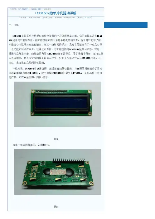
图1再来一张它的背面的,如图2所示:图2图3图4二.基本操作LCD1602的基本操作分为四种:1. 读状态:输入RS=0,RW=1,E=高脉冲。
输出:D0—D7为状态字。
2. 读数据:输入RS=1,RW=1,E=高脉冲。
输出:D0—D7为数据。
3. 写命令:输入RS=0,RW=0,E=高脉冲。
输出:无。
4. 写数据:输入RS=1,RW=0,E=高脉冲。
输出:无。
读操作时序图(如图5):图5写操作时序图(如图6):图6时序时间参数(如图7):图7三.DDRAM、CGROM和CGRAMDDRAM(Display Data RAM)就是显示数据RAM,用来寄存待显示的字符代码。
共80个字节,其地址和屏幕的对应关系如下(如图8):图8DDRAM相当于计算机的显存,我们为了在屏幕上显示字符,就把字符代码送入显存,这样该字符就可以显示在屏幕上了。
同样LCD1602共有80个字节的显存,即DDRAM。
但LCD 1602的显示屏幕只有16×2大小,因此,并不是所有写入DDRAM的字符代码都能在屏幕上显示出来,只有写在上图所示范围内的字符才可以显示出来,写在范围外的字符不能显示出来。
这样,我们在程序中可以利用下面的“光标或显示移动指令”使字符慢慢移动到可见的显示范围内,看到字符的移动效果。
前面说了,为了在液晶屏幕上显示字符,就把字符代码送入DDRAM。
例如,如果想在屏幕左上角显示字符‘A’,那么就把字符‘A’的字符代码41H写入DDRAM的00H地址处即可。
至于怎么写入,后面会有说明。
那么为什么把字符代码写入DDRAM,就可以在相应位置显示这个代码的字符呢?我们知道,LCD1602是一种字符点阵显示器,为了显示一种字符的字形,必须要有这个字符的字模数据,什么叫字符的字模数据,看看下面的这个图就明白了(如图9)。
图9上图的左边就是字符‘A’的字模数据,右边就是将左边数据用“○”代表0,用“■”代表1。
从而显示出‘A’这个字形。
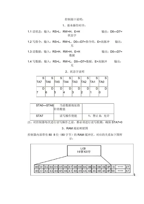
控制接口说明:1、基本操作时序:1.1读状态:输入:RS=L,RW=H,E=H 输出:D0—D7=状态字1.2写指令:输入:RS=L,RW=L,D0—D7=指令码,E=高脉冲输出:无1.3读数据:输入:RS=H,RW=H,E=H 输出:D0—D7=数据1.4写数据:输入:RS=L,RW=L,D0—D7=数据,E=高脉冲输出:无2、状态字说明3、RAM地址映射图控制器内部带有80×8位(80字节)的RAM缓冲区,对应的关系如下图所示:4、指令说明4.1初始化设置显示模式设置控制器内部设有一个数据地址指针,可通过它们来访问内部的全部80字节RAM。
数据指针设置:延时15ms写指令38H(不检测忙信号)延时5ms写指令38H(不检测忙信号)延时5ms写指令38H(不检测忙信号)(以后每次写指令、读/写数据操作之前均需检测忙信号)写指令38H:显示模式设置写指令08H:显示关闭写指令01H:显示清屏写指令06H:显示光标移动设置写指令0CH:显示开及光标设置原文出自:/47okey/blog/item/809c7cfc8dd6541c08244d60.html程序分析:、程序清单:RS BIT P3.7 ;RS1602液晶的数据命令控制端,高电平为数据,低电平为指令;这3位是液晶屏的控制信号,连接方式由具体硬件而定RW BIT P3.6;RW1602液晶的读写控制端,高电平为读,低电平为写E BIT P3.5;E1602的使能端ORG 0000H;程序开始LJMP MAIN;跳转到MAIN处执行程序ORG 0100H;数据存放地址MAIN:LCALL DISPLAY;调用液晶显示子程序LCALL D1S;延时1秒LJMP MAIN;返回到MAIN处;-------液晶显示的子程序(显示前先格式转换)---------------------------------------DISPLAY:LCALL INITIAL;调用初始化子程序MOV A, #10000000B ; LINE1: DB 'This is a TEST',00H,设置第一行的显示地址LCALL WRITE_INSTRUCTION;调用写液晶命令子程序MOV DPTR, #LINE1;将表格1送到DPTR中LCALL PR_STRING;调用写字符子程序LCALL WRITE_LCDDATA;调用写液晶数据子程序MOV A, #11000000B ; LINE2: DB'Design by 47okey',00H,设置第二行的显示地址LCALL WRITE_INSTRUCTION;调用写液晶命令子程序MOV DPTR, #LINE2;将表格2送到DPTR中LCALL PR_STRING;调用写字符子程序RET;---液晶屏初始化,具体请参考资料-------------------------------------------------initial: MOV A, #01H;01H这个指令是设置1602的清屏操作LCALL WRITE_INSTRUCTION;调用液晶命令写入子程序MOV A, #38H;38H这个指令是设置1602的显示模式,2行,16个字符/行LCALL WRITE_instruction;调用液晶命令写入子程序MOV A, #0FH;0FH这个指令是设置1602的显示、显示光标、光标闪烁LCALL WRITE_instruction;调用液晶命令写入子程序MOV A, #06H;06H这个指令是设置1602的输入方式,增量不移位LCALL WRITE_instruction;调用液晶命令写入子程序RET;----写液晶指令的子程序------------------------------------------WRITE_instruction: MOV P1, A;将累加器A中的命令送到P0口做输出数据CLR RS ;写入控制命令,RS低电平为命令CLR RW;读写控制端,RW,低电平为写,就是写命令CLR E;使能端,E发生电平跳变就开始写入命令LCALL DELAY;调用延时子程序,也就是下面写的判断液晶模块是否处于忙状态SETB E;使能端,E发生电平跳变完成,写入命令完成RET;----写液晶数据的子程序---------------------------------------------write_lcddata: MOV P1, A;将累加器A中的数据送到P0口做输出数据SETB RS ;写入显示数据,RS高电平为数据CLR RW;读写控制端,RW低电平为写数据CLR E;使能端E,低电平LCALL DELAY ;判断液晶模块是否忙?SETB E;使能端,E发生电平跳变完成,写入数据完成RET;-----写行字符的子程序---------------------------------------------------------------PR_STRING: CLR A;将累加器A中的内容做清零操作MOVC A, @A+DPTR;查表,将查到的数据送到累加器A中去JZ END_PR;JZ为累加器A判0转移指令,若A 中不为0则往下执行程序,为0则跳转到END_PR处LCALL WRITE_LCDDATA;调用写液晶数据的的子程序INC DPTR;DPTR地址加一LJMP PR_STRING;跳转到PR_STRING处执行程序END_PR: RET;----查看液晶忙碌信号的子程序---------------------------------------------------------DELAY: MOV P1,#0FFH ;判断液晶显示器是否忙的子程序 CLR RS;RS低电平,写命令SETB RW;RW高电平,读液晶内部的数据CLR E;使能端低电平NOP;延时一个机器周期SETB E;使能端高电平JB P1.7,DELAY ;如果P1.7为高电平表示忙就循环等待,JB判bit转移,bit为1则跳转,否则顺序执行程序 RET;---1mS延时(按12MHZ算)-----------------------------------------------------------------D1mS: MOV R7,#250LOOP0: NOPNOPDJNZ R7,LOOP0RET;----1S延时(按12MHZ算)-----------------------------------------------------------------D1S: Mov R6,#4LOOP2: mov R5,#250LOOP1: LCALL D1mSDJNZ R5,LOOP1DJNZ R6,LOOP2RET;--------------------------------------------------------------------------------------LINE1: DB 'This is a TEST !',00HLINE2: DB 'Design by 47okey',00HEND。

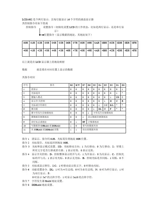
LCD1602是个两行显示,且每行能显示16个字符的液晶显示器其控制指令有如下组成控制指令--------设置指令(初始化设置LCD的工作状态,比如是两行显示,还是单行显示)以上就是在LCD显示器上的地址映射数据-----------就是要在对应位置上显示的数据其指令对应指令1 清显示,指令码01H,光标复位到地址00H位置。
指令2 光标复位,光标返回到地址00H。
指令3 光标和显示模式设置。
I/D:光标移动方向,1为右移动,0为左移动。
S:屏幕上所有文字是否左移或者右移。
1表示有效,0表示无效。
指令4 显示开关控制。
D:控制整体显示的开与关,1为开显示,0为关显示。
C:控制光标的开与关,1表示有光标,0表示无光标。
B:控制光标是否闪烁,1闪烁,0不闪烁。
指令5 光标或显示移位。
S/C:1时移动显示的文字。
0时移动光标。
指令6 功能设置命令。
DL:1时为4位总线,0时为8位总线。
N:0时为单行显示,1时为双行显示。
F:0时显示5x7的点阵字符,1时显示5x10的点阵字符。
指令7 字符发生器RAM地址设置。
指令8 DDRAM地址设置。
指令9 读忙信号和光标地址。
BF:为忙标志位,1时表示忙,此时模块不能接收命令或数据,如果为0表示不忙。
指令10 写数据。
指令11 读数据。
管脚说明RS 数据寄存器与指令寄存器的选择端口,RS=0,为指令寄存器,RS=1,为数据寄存器RW 为读写操作,RW=1,为读,RW=0,为写E 使能端,,下降沿使能LCD作用D0---D7 8位数据端口LCD的操作初始化LCD----数据操作----返回总的说来,就是先初始化LCD,在写入地址指令,在写入显示数据初始化LCD(设置LCD的工作状态,其指令如上面框图)参考程序如下(delay为延时,lcd_wcmd为写指令函数)void lcd_init(){ lcd_wcmd(0x38);delay(300);lcd_wcmd(0x0c);delay(300);lcd_wcmd(0x06);delay(300);lcd_wcmd(0x01);delay(300);}初始化完后就可以进行对LCD的操作,但是不管是写指令还是写数据,先要判断其状态(因为它是个慢显示)忙碌判断参考程序如下(da为八位数据口)bit lcd_bz(){ bit result;rs = 0;//选择指令寄存器rw = 1;//读操作ep = 1;delay(3);result = (bit)(da & 0x80);//读取忙碌标志ep = 0;//模拟一个下降沿,使能LCDreturn result;//返回忙碌标志}在写数据之前要先写入地址指令参考程序如下void lcd_wcmd(unsigned char cmd){while(lcd_bz()); //判断LCD忙碌rs = 0;//指令寄存器rw = 0;//写操作ep = 0;delay(3);da= cmd;//写入指令delay(3);ep = 1;delay(3);ep = 0;//模拟一个下降沿,使能LCD}注意初始化那写指令也是用的这个程序,但是区别在于写地址指令时候,cmd变量的最高位要恒为1 比如写03H这个地址指令,则cmd的值要为0x83,这样才会正确地显示地址指令写完后,就可以写入数据参考程序如下(dat为写入的数据)void lcd_wdat(unsigned char dat){while(lcd_bz()); //判断LCD忙碌rs = 1;//数据寄存器rw = 0;//写操作ep = 0;da = dat;//写入数据delay(3);ep = 1;delay(3);ep = 0;//模拟一个下降沿,使能LCD}注意 1. 初始化LCD只需在主程序中执行一次就可。
在日常生活中,我们对液晶显示器并不陌生。
液晶显示模块已作为很多电子产品的通过器件,如在计算器、万用表、电子表及很多家用电子产品中都可以看到,显示的主要是数字、专用符号和图形.在单片机的人机交流界面中,一般的输出方式有以下几种:发光管、LED数码管、液晶显示器.发光管和LED数码管比较常用,软硬件都比较简单,在前面章节已经介绍过,在此不作介绍,本章重点介绍字符型液晶显示器的应用。
在单片机系统中应用晶液显示器作为输出器件有以下几个优点:显示质量高由于液晶显示器每一个点在收到信号后就一直保持那种色彩和亮度,恒定发光,而不像阴极射线管显示器(CRT)那样需要不断刷新新亮点.因此,液晶显示器画质高且不会闪烁.数字式接口液晶显示器都是数字式的,和单片机系统的接口更加简单可靠,操作更加方便.体积小、重量轻液晶显示器通过显示屏上的电极控制液晶分子状态来达到显示的目的,在重量上比相同显示面积的传统显示器要轻得多.功耗低相对而言,液晶显示器的功耗主要消耗在其内部的电极和驱动IC上,因而耗电量比其它显示器要少得多.10.8.1 液晶显示简介①液晶显示原理液晶显示的原理是利用液晶的物理特性,通过电压对其显示区域进行控制,有电就有显示,这样即可以显示出图形。
液晶显示器具有厚度薄、适用于大规模集成电路直接驱动、易于实现全彩色显示的特点,目前已经被广泛应用在便携式电脑、数字摄像机、PDA移动通信工具等众多领域.②液晶显示器的分类液晶显示的分类方法有很多种,通常可按其显示方式分为段式、字符式、点阵式等。
除了黑白显示外,液晶显示器还有多灰度有彩色显示等。
如果根据驱动方式来分,可以分为静态驱动(Static)、单纯矩阵驱动(Simple Matrix)和主动矩阵驱动(Active Matrix)三种。
③液晶显示器各种图形的显示原理:线段的显示点阵图形式液晶由M×N个显示单元组成,假设LCD显示屏有64行,每行有128列,每8列对应1字节的8位,即每行由16字节,共16×8=128个点组成,屏上64×16个显示单元与显示RAM区1024字节相对应,每一字节的内容和显示屏上相应位置的亮暗对应。
HD44780内置了DDRAM、CGROM和CGRAM。
DDRAM就是显示数据RAM,用来寄存待显示的字符代码。
共80个字节,其地址和屏幕的对应关系如下表:也就是说想要在LCD1602屏幕的第一行第一列显示一个"A"字,就要向DDRAM的00H地址写入“A”字的代码就行了。
但具体的写入是要按LCD模块的指令格式来进行的,后面我会说到的。
那么一行可有40个地址呀?是的,在1602中我们就用前16个就行了。
第二行也一样用前16个地址。
对应如下:DDRAM地址与显示位置的对应关系(事实上我们往DDRAM里的00H地址处送一个数据,譬如0x31(数字1的代码)并不能显示1出来。
这是一个令初学者很容易出错的地方,原因就是如果你要想在DDRAM 的00H地址处显示数据,则必须将00H加上80H,即80H,若要在DDRAM的01H处显示数据,则必须将01H加上80H即81H。
依次类推。
大家看一下控制指令的的8条:DDRAM地址的设定,即可以明白是怎么样的一回事了)1602液晶模块内部的字符发生存储器(CGROM)已经存储了160个不同的点阵字符图形,如下表所示,这些字符有:阿拉伯数字、英文字母的大小写、常用的符号、和日文假名等,每一个字符都有一个固定的代码,比如大写的英文字母“A”的代码是01000001B (41H),显示时模块把地址41H中的点阵字符图形显示出来,我们就能看到字母“A”上表中的字符代码与我们PC中的字符代码是基本一致的。
因此我们在向DDRAM 写C51字符代码程序时甚至可以直接用P1='A'这样的方法。
PC在编译时就把“A”先转为41H代码了。
字符代码0x00~0x0F为用户自定义的字符图形RAM(对于5X8点阵的字符,可以存放8组,5X10点阵的字符,存放4组),就是CGRAM了。
后面我会详细说的。
0x20~0x7F为标准的ASCII码,0xA0~0xFF为日文字符和希腊文字符,其余字符码(0x10~0x1F及0x80~0x9F)没有定义。
LCD1602数据手册一、概述LCD1602 是一种广泛应用于各类电子设备中的字符型液晶显示模块。
它具有体积小、功耗低、显示清晰等优点,能够显示 16 个字符乘以 2行的信息,非常适合用于显示简单的文本和数据。
二、基本特性1、显示容量:LCD1602 可以显示 32 个字符,即 16 个字符乘以 2 行。
2、工作电压:通常为 5V 直流电源。
3、显示模式:可以显示字母、数字、符号等多种字符。
4、视角范围:具有一定的可视角度,在不同角度下仍能清晰看到显示内容。
三、引脚功能1、 VSS:接地引脚。
2、 VDD:电源引脚,接+5V 电源。
3、 V0:对比度调整引脚,通过外接电位器来调整液晶显示的对比度。
4、 RS:寄存器选择引脚。
当 RS 为低电平时,选择指令寄存器;当 RS 为高电平时,选择数据寄存器。
5、 RW:读写选择引脚。
当 RW 为低电平时,进行写操作;当 RW 为高电平时,进行读操作。
6、 E:使能引脚,下降沿触发。
7、 D0 D7:数据引脚,用于传输指令和数据。
四、指令集1、清屏指令:将显示缓冲区的内容清除,屏幕显示空白。
2、归位指令:使光标回到起始位置,即第一行第一列。
3、输入方式设置指令:用于设置数据的输入方式,如光标移动方向等。
4、显示开关控制指令:控制显示、光标、闪烁等功能的开启和关闭。
5、光标或显示移位指令:使光标或整个显示内容向左或向右移动。
6、功能设置指令:设定数据长度、行数、字形等参数。
7、 CGRAM 地址设置指令:用于自定义字符的地址设置。
8、 DDRAM 地址设置指令:指定显示数据的存储地址。
五、显示缓冲区LCD1602 内部具有显示缓冲区,通过向缓冲区写入数据来控制显示内容。
第一行的地址为 0x00 0x0F,第二行的地址为 0x40 0x4F。
六、初始化设置在使用LCD1602 之前,需要进行初始化设置,包括设置显示模式、输入方式、显示开关等。
以下是一个常见的初始化流程示例:1、延时 15ms 以上。
lcd1602 使用手册,LCD1602 的使用详解LCD1602 是很多单片机爱好者较早接触的字符型液晶显示器,它的主控芯片是HD44780 或者其它兼容芯片。
刚开始接触它的大多是单片机的初学者。
由于对它的不了解,不能随心所欲地对它进行驱动。
经过一段时间的学习,我对它的驱动有了一点点心得,今天把它记录在这里,以备以后查阅。
一般来说,LCD1602 有16 条引脚,据说还有14 条引脚的,与16 脚的相比缺少了背光电源A(15 脚)和地线K(16 脚)。
我手里这块LCD1602 的型号是HJ1602A,是绘晶科技公司的产品,它有16 条引脚。
LCD1602 的基本操作1. 读状态:输入RS=0,RW=1,E=高脉冲。
输出:D0D7 为状态字。
2. 读数据:输入RS=1,RW=1,E=高脉冲。
输出:D0D7 为数据。
3. 写命令:输入RS=0,RW=0,E=低脉冲。
输出:无。
(写完置E= 高脉冲)4. 写数据:输入RS=1,RW=0,E=低脉冲。
输出:无。
分析时序图(1)写操作(单片机至HD44780)首先要对寄存器的选择和读、写操作选择进行配置。
RS 是寄存器选择,RS = 1 对数据进行操作;RS = 0 对指令进行操作。
接着对读写操作选择进行配置,RW = 0 写操作。
打开使能端,输入使能信号E = 1。
数据总线,对DB0~DB7 赋值,进行数据的传输【注】如果先打开使能,再进行其他配置的话,有可能传输的数据不是自己想要的。
(2)读操作(HD44780 至单片机)显示模块的指令集,根据自己的显示需要进行相应的配置显示的位置设置DDRAM显示在第一行某一列的数据可以写命令:0x80 | 0x**,显示在第二行某一列的数据可以写命令:0x80 | 0x40 | 0x** = 0xC0 | 0x**,0x80 是因为在设置DDRAM 地址时,DB7 固定是为1 的。
LCD1602 写入自己的字符及显示汉字1、由于LCD 是外部设备,处理速度比CPU 速度慢,向LCD 写入命令到完成功能需要一定的时间,在这个过程中,LCD 处于忙状态,不能向LCD 写入新的内容。
LCD1602帮助手册正面图背面图正面图为第一图,管脚应排列在左上方,左边第一脚为管脚1,向右依次为2,3,4………15,16。
背面一般也有标注,并且附带了管脚对应的作用。
其中第三脚VO为对比度调节脚,一般外接滑动变阻器,调节输入的电压,来调节明暗度(可以直接接地,不过直接接地,需要斜着屏幕,才能看见LCD是否显示字符,正面看都是黑黑的一格一格的)。
15,16角一般为背光LED灯源,一个接VCC(一般为15脚),一个接GND(一般为16脚),最好接入限流电阻,不接也可使用,不过会缩短寿命,这两角可以不接,如果不接,在黑暗的室内,显示效果欠佳。
管脚编号如下图所示:管脚对应符号对LCD的操作,有四种操作,分别为:读状态,读数据,写指令和写数据,一般常用的为读状态,写指令和写数据。
操作图如下:当RS端为低电平,RW端为高电平,E为高电平是,对LCD1602的操作为读状态操作,这时,可以对LCD的状态进行读取,读取通过D0~D7的端口读取。
其他操作相似,对照图,即可完成,但是有个读写时序的要求,时序图见下图:读操作时序对LCD进行读操作时,先将RS置为低电平(0V),然后将RW样置为高电平(+5V),然后有个tsp1的延迟(但是一般这个延迟为ns级,一个单片机的指令周期通常都为us级,一般不需要特别延迟,如果程序有一定错误的时候,可以稍微延迟一下),然后再将E置为1,然后延迟td时间(td一般也为ns级,可以适当延迟一点点),然后读取D0~D7的数据。
写操作也是类似的,将RS,RW,E端口进行相应操作即可完成,写数据和写命令的操作,延迟的时间都很短,程序不稳定的话,可以延迟个1us,一般就可以了。
LCD1602的指令有11条,如下图:(指令表)从之前的操作来看,对照此表,不难看出,指令表的前8条都是命令指令,RS,RW都为0,所以操作时,都是写命令操作,D7~D0的数值的不同,代表了操作的不同,比如D0~D7为0x01时,对LCD的操作命令就为清屏显示,第二条指令为光标返回指令,在D0处有个※标记,这表示,不论此位的数据为1还是为0,对此命令都无效,即D0~D7端口写入0x20为光标返回指令,D0~D7端口写入0x03,此命令也为光标返回指令。
LCD1602数据⼿册1602LCD主要技术参数:显⽰容量:16×2个字符芯⽚⼯作电压:4.5—5.5V⼯作电流:2.0mA(5.0V)模块最佳⼯作电压:5.0V字符尺⼨:2.95×4.35(W×H)mm引脚功能说明1602LCD采⽤标准的14脚(⽆背光)或16脚(带背光)接⼝,各引脚接⼝说明如表10-13所⽰:编号符号引脚说明编号符号引脚说明1VSS电源地9D2数据2VDD电源正极10D3数据3VL液晶显⽰偏压11D4数据4RS数据/命令选择12D5数据5R/W读/写选择13D6数据6E使能信号14D7数据7D0数据15BLA背光源正极8D1数据16BLK背光源负极表10-13:引脚接⼝说明表第1脚:VSS为地电源。
第2脚:VDD接5V正电源。
第3脚:VL为液晶显⽰器对⽐度调整端,接正电源时对⽐度最弱,接地时对⽐度最⾼,对⽐度过⾼时会产⽣“⿁影”,使⽤时可以通过⼀个10K 的电位器调整对⽐度。
第4脚:RS为寄存器选择,⾼电平时选择数据寄存器、低电平时选择指令寄存器。
第5脚:R/W为读写信号线,⾼电平时进⾏读操作,低电平时进⾏写操作。
当RS和R/W共同为低电平时可以写⼊指令或者显⽰地址,当RS 为低电平R/W为⾼电平时可以读忙信号,当RS为⾼电平R/W为低电平时可以写⼊数据。
第6脚:E端为使能端,当E端由⾼电平跳变成低电平时,液晶模块执⾏命令。
第7~14脚:D0~D7为8位双向数据线。
第15脚:背光源正极。
第16脚:背光源负极。
1602LCD的指令说明及时序1602液晶模块内部的控制器共有11条控制指令,如表10-14所⽰:序号指令RS R/W D7D6D5D4D3D2D1D01清显⽰00000000012光标返回000000001*3置输⼊模式00000001I/D S4显⽰开/关控制0000001D C B5光标或字符移位000001S/C R/L**6置功能00001DL N F**7置字符发⽣存贮器地址0001字符发⽣存贮器地址8置数据存贮器地址001显⽰数据存贮器地址9读忙标志或地址01BF计数器地址10写数到CGRAM或10要写的数据内容DDRAM)11读出的数据内容11从CGRAM或DDRAM读数表10-14:控制命令表1602液晶模块的读写操作、屏幕和光标的操作都是通过指令编程来实现的。
PRODUCT : MODEL NO. : SUPPLIER REVISION : :LCM HC1624-B-LWH TSINGTEK DISPLAY CO.,LTD B E-mail:sales@TSINGTEK DISPLAY CO.,LTDREV . BHC1624-B-LWHRev NO. A BRev Date Jan. 10,2007 Oct.8,2008 Apr.23,2011CONTENS First Release RoHS Compliant Modify the 1.4 sectionREMARKS-1-TSINGTEK DISPLAY CO.,LTDREV . BHC1624-B-LWHPRODUCT CODING SYSTEM HG ⑴ 320240 ⑵ C– ⑶ B⑷ LW ⑸ H⑹ NV⑺ L4⑻ TPSD⑼ U⑽ T ⑾⑴:Brand and Display Type HC→Tsingtek Character Type HG→Tsingtek SMT/COB Graphic Type HGT→Tsingtek TAB Type HGO→Tsingtek COG Type HGR→Tsingtek CSTN HGF→Tsingtek TFT HGS→Tsingtek OLED HCS→Tsingtek Character Type OLED ⑵:Character→Words per lines×lines Graphic→row dots×column dots ⑶:Series No. ⑷: LCD module: Nil→STN Yellow-Green Mode G→STN Gray Mode B→STN Blue Mode F→FSTN Transflective T→FSTN Transmission OLED module: Y→Yellow G→Green B→Blue W→White ⑸:Backlight Type Nil→Without Backlight LY→LED Yellow-Green Array SY→LED Yellow-Green Edge LW→LED White LB→LED Blue LR→LED Red LA→LED Amber LG→LED GreenEB→EL Blue EG→EL Green EW→EL White CW→CCFL White ⑹:Temperature Nil→Normal Temperature H→Wide Temperature EH→Super Wide Temperature ⑺:Power Supply Nil→5V NV→5V Without Booster for LCM Driving Supply SV→5V With Temperature Compensation LV→3.3V LNV→3.3V Without Booster for LCM Driving Supply LSV→3.3V With Temperature Compensation OV→Please refer to the spc.of LCM ⑻:Power supply for Backlight Please refer to the spc.of LCM ⑼:Special Coding TP→With Touch Panel S→Serial Interface ⑽:Viewing Direction Nil→6:00 U→12:00 L→9:00 R→3:00 ⑾:Interior Coding-2-TSINGTEK DISPLAY CO.,LTDREV . BHC1624-B-LWHCONTENTS1. BASIC SPECIFICATIONS……..…………………………….....…..(2) 2. ABSOLUTE MAXIMUM RATING……………………………..….. (4) 3. ELECTRICAL CHARACTERISTICS…………………..…….…....(4) 4. TIMING CHARACTERISTICS…………………………………….. (5) 5. COMMANDS AND FUNCTION DESCRIPTIONS..…………......(6) 6. QUALITY SPECIFICATIONS………………………..…………...(25) 7. RELIABILITY…………………………………………………......(26) 8. TEST REPORT…………………………………………………….(27) 9. PRECAUTIONS FOR USING LCD MODULES………………...(27) 10. PRECAUTIONS FOR CUSTOMER………………………….….. (29)-1-TSINGTEK DISPLAY CO.,LTDREV . BHC1624-B-LWH1. BASIC SPECIFICATIONS1.1 DISPLAY SPECIFICATIONITEM DISPLAY TYPE COLOR INPUT DATA DUTY VIEW ANGLE CONTROLLER BEZEL BACKLIGHT OPERATING TEMPERATURE STORAGE TEMPERATURE OTHERS SPECIFICATION STN/BLUE/NEGATIVE/TRANSMISSIVE DISPLAY DOT: WHITE DISPLAY BACKGROUNTND: BLUE 68 SERIES 1/16DUTY 6 O’CLOCK SPLC780D1 0.6T LED (WHITE) -20 oC ~70 oC -30 oC ~ 80 oC1.2MECHANICAL SPECIFICATIONITEM SPECIFICATION 80.0(W)×36.0(H)×13.0MAX.(T) 64.5(W)×13.8(H) 56.2(W)×11.5(H) 16Characters×2Lines 3.00(W)×5.55(H) 0.55(W)×0.65(H) UNIT mm mm mm --mm mm NOTEDIMENSIONAL OUTLINE VIEW AREA EFFECTIVE V/AREA NUMBER OF CHARACTERS CHARACTER PITCH DOT SIZE1.3BLOCK DIAGRAM-2-TSINGTEK DISPLAY CO.,LTDREV . BHC1624-B-LWH1.4 DIMENSIONAL OUTLINE2.54- 2.58.0@2.54X15=38.11.01.6 0.55113.8(V.A.)160.626.8± 0.211.5(A.A.)36.0± 0.331.00.6510.156.2(A.A.) 11.25 64.5(V.A.) 71.3± 0.2 75.0 80.0± 0.3 8.0± 0.30.05 3.0 0.42.53.6MAX 13.01.5 TERMINAL FUNCTIONSPIN NO. 1 2 3 4 5 6 7~14 15 16 SYMBOL VSS VDD V0 RS R/W E DB0~DB7 LEDA LEDK LEVEL 0V +5.0V 0V H/L H/L H-L H/L +5.0V 0V FUNCTION GND Power Supply for logic Operating voltage for LCD H: Data L: Instruction code L: WriteH: ReadChip Enable signal Data bus line Power Supply for LED Back Light1.6 POWER SUPPLY AND CONTRAST ADJUST CIRCUIT-3-0.055.55TSINGTEK DISPLAY CO.,LTDREV . BHC1624-B-LWH2. ABSOLUTE MAXIMUM RATINGSPARAMETER POWER SUPPLY FOR LOGIC POWER SUPPLY FOR LCD DRIVER INPUT VOLTAGE OPERATING TEMPERATURE STORAGE TEMPERATURE SYMBOL VDD-VSS VDD~V5 VIN Topr Tstg(Ta=25 oC, VSS=0V)RATINGS -0 .3~ 7.0 0 ~ 10.0 VSS ~ VDD -20 ~70 -30 ~ 80 UNITS V V Vo oC C3. ELECTRICAL CHARACTERISTICS3.1 ELECTRICAL CHARACTERISTICSITEM LOGIC CIRCUIT POWER SUPPLY VOLTAGE INPUT VOLTAGE INPUT VOLTAGE OUTPUT VOLTAGE OUTPUT VOLTAGE LOGIC CIRCUIT POWER SUPPLY CURRENT RECOMMENDED LCD DRIVING VOLTAGE SYMBOL CONDITION VDD –VSS VIL VIH VOL VOH IDD *VLCD Φ=0 θ=0 -----VDD –VSS =5.0V MIN 4.5 -0.3 2.2 0 2.4 --(Ta=25 oC ,VSS=0V)TYPE 5.0 ----1.1 MAX. 5.3 0.6 VDD 0.4 VDD -UNIT NOTE V V V V V mATa=25 oC--5.0--V*Note: VLCD is produced by module’s inside circuit, do not need the external input. The customer only need to offer +5.0V voltage which is stated in the interface definition.3.2 LED BACKLIGHT SPECIFICATIONITEM FORWARD VOLTAGE COLOR SYMBOL Vf MIN. 3.0 TYP. 3.1 MAX. 3.2 UNIT V CONDITIONS If= 30mAWHITE-4-TSINGTEK DISPLAY CO.,LTDREV . BHC1624-B-LWH4. TIMING CHARACTERISTICS 4.1 Write mode (Writing Data from MPU to SPLC780D1)4.2 Read mode (Reading Data from SPLC780D1 to MPU)4.3 Write mode timing diagram (Writing Data from MPU to SPLC780D1)-5-TSINGTEK DISPLAY CO.,LTDREV . BHC1624-B-LWH4.4 Read mode timing diagram (Reading Data from SPLC780D1 to MPU)5. COMMANDS AND FUNCTION DESCRIPTIONS 5.1 Control and Display InstructionsControl and display instructions are described in details as follows: 5.1.1 Clear displayIt clears the entire display and sets Display Data RAM Address 0 in Address Counter. 5.1.2 Return homeX: Do not care (0 or 1) It sets Display Data RAM Address 0 in Address Counter and the display returns to its original position. The cursor or blink goes to the most-left side of the display (to the 1st line if 2 lines are displayed). The contents of the Display Data RAM do not change.-6-TSINGTEK DISPLAY CO.,LTDREV . BHC1624-B-LWH5.1.3 Entry mode set During writing and reading data, it defines cursor moving direction and shifts the display.I / D = 1: Increment, I / D = 0: Decrement. S = 1: The display shift, S = 0: The display does not shift.5.1.4 Display ON/OFF controlD = 1: Display on, D = 0: Display off C = 1: Cursor on, C = 0: Cursor off B = 1: Blinks on, B= 0: Blinks off-7-TSINGTEK DISPLAY CO.,LTDREV . BHC1624-B-LWH5.1.5 Cursor or display shift Without changing DD RAM data, it moves cursor and shifts display.5.1.6 Function setX: Do not care (0 or 1) DL: It sets interface data length. DL = 1: Data transferred with 8-bit length (DB7 - 0). DL = 0: Data transferred with 4-bit length (DB7 - 4). It requires two times to accomplish data transferring. N: It sets the number of the display line. N = 0: One-line display. N = 1: Two-line display. F: It sets the character font. F = 0: 5 x 8 dots character font. F = 1: 5 x 10 dots character font. -8-TSINGTEK DISPLAY CO.,LTDREV . BHC1624-B-LWHIt cannot display two lines with 5 x 10 dots character font. 5.1.7 Set character generator RAM addressIt sets Character Generator RAM Address (aaaaaa)2 to the Address Counter. Character Generator RAM data can be read or written after this setting. 5.1.8 Set display data RAM addressIt sets Display Data RAM Address (aaaaaaa)2 to the Address Counter. Display data RAM can be read or written after this setting. In one-line display (N = 0), (aaaaaaa)2: (00)16 - (4F)16. In two-line display (N = 1), (aaaaaaa)2: (00)16 - (27)16 for the first line, (aaaaaaa)2: (40)16 - (67)16 for the second line. 5.1.9 Read busy flag and addressWhen BF = 1, it indicates the system is busy now and it will not accept any instruction until not busy (BF = 0). At the same time, the content of Address Counter (aaaaaaa)2 is read.-9-TSINGTEK DISPLAY CO.,LTDREV . BHC1624-B-LWH5.1.10 Write data to character generator RAM or display data RAMIt writes data (dddddddd)2 to character generator RAM or display data RAM. 5.1.11 Read data from character generator RAM or display data RAMIt reads data (dddddddd)2 from character generator RAM or display data RAM. To read data correctly, do the following: 1). The address of the Character Generator RAM or Display Data RAM or shift the cursor instruction. 2). The “ Read ” instruction.- 10 -TSINGTEK DISPLAY CO.,LTDREV . BHC1624-B-LWH5.2 Instruction Table- 11 -TSINGTEK DISPLAY CO.,LTDREV . BHC1624-B-LWH5.3 8-Bit Operation and 8-Digit 1-Line Display (Using Internal Reset)- 12 -TSINGTEK DISPLAY CO.,LTDREV . BHC1624-B-LWH5.4 4-Bit Operation and 8-Digit 1-Line Display (Using Internal Reset)5.5 8-Bit Operation and 8-Digit 2-Line Display (Using Internal Reset)- 13 -TSINGTEK DISPLAY CO.,LTDREV . BHC1624-B-LWH5.6 Reset FunctionAt power on, SPLC780D1 starts the internal auto-reset circuit and executes the initial instructions. The initial procedures are shown as follows:- 14 -TSINGTEK DISPLAY CO.,LTDREV . BHC1624-B-LWH5.7 Display Data RAM (DD RAM)The 80-bit DD RAM is normally used for storing display data. Those DD RAM not used for display data can be used as general data RAM. Its address is configured in the Address Counter.The relationships between Display Data RAM Address and LCD′s position are depicted as follows.- 15 -TSINGTEK DISPLAY CO.,LTDREV . BHC1624-B-LWH5.8 Character Generator ROM (CG ROM)Using 8-bit character code, the character generator ROM generates 5 x 8 dots or 5 x 10 dots character patterns. character patterns. It also can generate 192’s 5 x 8 dots character patterns and 64’s 5 x 10 dots5.9 Character Generator RAM (CG RAM)Users can easily change the character patterns in the character generator RAM through program. It can be written to 5 x 8 dots, 8-character patterns or 5 x 10 dots for 4-character patterns.- 16 -TSINGTEK DISPLAY CO.,LTDREV . BHC1624-B-LWHThe following diagram shows the SPLC780D1 character patterns: Correspondence between Character Codes and Character Patterns.- 17 -TSINGTEK DISPLAY CO.,LTDREV . BHC1624-B-LWHThe relationships between Character Generator RAM Addresses, Character Generator RAM Data (character patterns), and Character Codes are depicted as follows: 5.9.1 5 x 8 dot character patterns- 18 -TSINGTEK DISPLAY CO.,LTDREV . BHC1624-B-LWH5.9.25 X 10 dot character patterns5.10 Cursor/Blink Control CircuitThis circuit generates the cursor or blink in the cursor / blink control circuit. The cursor or the blink appears in the digit at the Display Data RAM Address defined in the Address Counter. When the Address Counter is (07) 16, the cursor position is shown as belows:- 19 -TSINGTEK DISPLAY CO.,LTDREV . BHC1624-B-LWH5.11 Interfacing to MPUThere are two types of data operations: 4-bit and 8-bit operations. interfacing 4-bit data is transferred by 4-busline (DB4 to DB7). Using 4-bit MPU, the Thus, DB0 to DB3 bus lines are First, thenot used. Using 4-bit MPU to interface 8-bit data requires two times transferring. higher 4-bit data is transferred by 4-busline (for 8-bit operation, DB7 to DB4). lower 4-bit data is transferred by 4-busline (for 8-bit operation, DB3 to DB0). 8-bit data is transferred by 8-buslines (DB0 to DB7).Secondly, theFor 8-bit MPU, the- 20 -TSINGTEK DISPLAY CO.,LTDREV . BHC1624-B-LWH- 21 -TSINGTEK DISPLAY CO.,LTDREV . BHC1624-B-LWH5.12 REGISTER --- IR (Instruction Register) and DR (Data Register)SPLC780D1 contains two 8-bit registers: Instruction Register (IR) and Data Register (DR). combinations of the RS pin and the R/W pin selects the IR and DR, see below: UsingThe IR can be written by MPU, but it cannot be read by MPU.5.13 Busy Flag (BF)When RS = 0 and R/W = 1, the busy flag is output to DB7. As the busy flag =1, SPLC780D1 is in busy state and does not accept any instruction until the busy flag = 0.- 22 -TSINGTEK DISPLAY CO.,LTDREV . BHC1624-B-LWH5.14 Address Counter (AC)The Address Counter assigns addresses to Display Data RAM and Character Generator RAM. When an instruction for address is written in IR, the address information is sent from IR to AC. After writing to/reading from Display Data RAM or Character Generator RAM, AC is automatically incremented by one (or decremented by one). The contents of AC are output to DB0 - DB6 when RS = 0 and R/W = 1.- 23 -TSINGTEK DISPLAY CO.,LTDREV . BHC1624-B-LWH5.15 CHARACTER GENERATOR ROMSPLC780D1 – 001A:- 24 -TSINGTEK DISPLAY CO.,LTDREV . BHC1624-B-LWH6. QUALITY SPECIFICATIONS6.1 ACCEPTABLE QUALITY LEVELInspection itemsVisual-operating (Electro-optical)Sampling proceduresGB2828-81 Inspection level Ⅱ Normal inspection Single sample inspection GB2828-81 Inspection level Ⅱ Normal inspection Single sample inspection GB2828-81 Inspection level Ⅱ Normal inspection Single sample inspectionAQL0.65Visual-not operating1.5Dimension measurement1.56.2 INSPECTION CONDITIONS(THE ENVIRONMENTAL)-Room temperature: 25±3 oC -Humidity: 65±20%RH6.3 INSPECTION STANDARDS 6.3.1 VISUAL WHILE OPERATINGItems to be inspected . No display . Irregular operating .Irregular display . Over current .View angles .Contrast .LCD operate voltage Inspection standard . If any pattern is not active at all, they can be rejected. . No irregular operating are allowed . Appeared different display, which they should be chosen in the pattern, or appeared in different position where they should be chosen. . Any segment doesn’t active, they can be rejected. . The total current required to activate the module should not be exceed the MAX current in specification. . Valves that don’t meet the minimum value noted in the specification. they can be rejected. . Valves that don’t meet the minimum value noted in the specification, they can be reject. . Meet the specification.- 25 -TSINGTEK DISPLAY CO.,LTDREV . BHC1624-B-LWH6.3.2Visual while not operatingModule dimension . Meet the module outline drawing, not exceed the tolerance. .Following scratches inside the effective viewing area considered as the defects when their width & length are larger than the following combinations. Number: one or more Width: 0.15 length: 5.0 two or more Width: 0.10 length: 3.0 three or more Width: 0.05 length: 2.0 When the defects exceed this, it can be rejected.LCD panel scratch7.RELIABILITYTest Item High temperature storage Low temperature storage High temperature operation Low temperature operation High temperature /Humidity storage High temperature /Humidity operation Content of Test Endurance test applying the high storage temperature for a long time Endurance test applying the low storage temperature for a long time Endurance test applying the electic stress (Voltage and Current)and the thermal stress to the element for a long time Endurance test applying the electic stress under low temperature for a long time Endurance test applying the high temperature and high humidity storage for a long time Endurance test applying the electic stress (Voltage and Current)and temperature /Humidity stress to the element for a long time Endurance test applying the low and high Temperature cycle -10℃→25℃→60℃ 30min←5min←30min 1 cycle Vibration test Endurance test applying the vibration during transportation and using 10~22Hz→1.5mmp-p 22~500Hz→1.5G Total 0.5hrs Test Condition 60℃ 200hrs -10℃ 200hrs 50℃ 200hrs 0℃ 200hrs 60℃,90%RH 96hrs 40℃,90%RH 96hrsTemperature cycle-10℃/60℃ 10 cycleNote 1: Condensation of water is not permitted on the module. Note 2: The module should be inspected after 4 hour storage in normal- 26 -TSINGTEK DISPLAY CO.,LTDREV . BHC1624-B-LWH8.TEST REPORTItem High temp. storage Low temp. storage High temp. operation Low temp. operation High temp. & humi. Storage Condition 80℃,120 hrs –30℃,120 hrs 70℃,240 hrs –20℃,240 hrs 50℃,90% RH,120 hrs -10℃,30min→+25℃, 5min→+60℃,30min(VDD=5V ,Ta=25℃) Standard Appearance without defect Appearance without defect Appearance without defect Appearance without defect Appearance without defect Appearance without defect Appearance without defect Note ------------10 cyclesHigh temp .& humi.Operation 40℃,90% RH,120 hrs Thermal shock9. PRECAUTIONS FOR USING LCD MODULES9.1 PrecautionTo our module ,we have made accurately assembly and debugging .So customer should do as follows: (1)Modules use LCD elements, so we must be treated as such avoid intense shock 、impact 、 extrusion and falls from a height. (2)Avoid to twist and disassemble module’s buckle legs. (3)Avoid to operate modules on the table if it's surface have printed circuit (4)Avoid to touch 、adjust and modify the rubber that connects LCD and PCB. (5)Avoid to add DC(direct current) in module. (6)Liquid crystal is harmful Substances .When liquid crystal leaked out and contacted to your hand、body or clothes ,you must wash it immediately with soap.9.2 Caution Of MountingThe panel of the LCD module consists of two thin glass plates with polarizes which easily get damaged since the module is fixed by utilizing fitting holes in the printed circuit board. Extreme care should be taken when handling the LCD modules.9.3 Caution Of LCD Handling & CleaningWhen cleaning the display surface. Use soft cloth with solvent (recommended below) and wipe lightly. -Isopropyl alcohol -Ethyl alcohol Do not wipe the display surface with dry or hard materials that will damage the polarizes surface. Do not use the following solvent: -Water -Ketone - 27 -TSINGTEK DISPLAY CO.,LTDREV . BHC1624-B-LWH- Aromatics9.4 Caution Against Static ChargeThe LCD modules use COMS LSI drivers. So we recommend that you connect any unused input terminal to Vdd or Vss, do not input any signals before power is turned on and ground your body. work/assembly table. And assembly equipment to protect against static electricity. the following ways are recommended. (1) If you doesn't intend to mount,please don't take module from bag.The module's packaging bag is handled by antistatic technology. (2) If you intend to operate module that you must make sure your body is good grounding , keeping your body and module at the same level. (3) The operating equipment requires to good grounding , especially the driver .In order to avoid interference we must make sure good grounding and no leakage. (4) Each module have a protective film .It is used to avoid the polaroid LCD is scratched or polluted .Please peel off the Protective Film slowly ,or else will produce static . (5) The humidity range at workshop: 50 ~ 60% RH9.5 Current Protection DevicesModule was not equipped with current protection devices, so we must prepared the current protection devices for using.The proportion of DC voltage is as small as possible ,preferably no more than 50mV.Or else it will cause electrochemical reaction after a time .9.6Caution For Operation-It is indispensable to drive LCM within the specified voltage limit since the higher voltage than the limit shortens LCM life. -Response time will be extremely delayed at lower temperature than the operating temperature range and on the other hand at higher temperature LCD show dark color in them. However those phenomena do not mean malfunction or out of order with LCD, which will come back in the specified operating temperature range. -If the display area is pushed hard during operation. Some font will be abnormally displayed but it resumes normal condition after turning off once. -A slight dew depositing on terminals is a cause for Electro-chemical reaction resulting in terminal open circuit. Under the maximum operating temperature, 50%RH or less is required9.7 Caution For SolderingIf need soldering,we must notice as follows: ※ Except the connect position of INPUT and OUTPUT doesn’t allow to soldering. ※ Soldering iron required to be insulated. (1)Soldering Conditions: Iron Temperature : 280℃±10℃ Soldering Time: ﹤3-4S Soldering Materials: Low melting point, can be fully molten solder - 28 -TSINGTEK DISPLAY CO.,LTDREV . BHC1624-B-LWH(2)Caution for repeat soldering: Because connect line is through module's pad connected to module. Removing the line we must wait until the solder is completely melted . If solder doesn't completely melted , it is easily lead to the pad damage or ing “ XI QIANG” is the best way to remove the connect line .Besides, we must notice that repeat soldering doesn’t allow more than three time.9.8 Packaging And StorageWhen module needs to store a long time ,we should do as follows.If storage method is improper,it will have an effect on the Polaroid ,causing display not good.Meanwhile pads are easily oxidized lead to soldering didn't easily . (1)As far as possible to use the original packaging bag. (2)If we intend to store bulk modules ,we should put them in anti-static bag and sealing . (3)To prevent modules from degradation, do not operate or store them exposed directly to sunshine or high temperature/humidity. (4)The reasonable storage method is low humidity, temperature in 0℃ to 35℃ (5)Storing with no touch on polarizes surface by the anythingelse.10.PRECAUTIONS FOR CUSTOMER(1)A limit sample should be provided by the both parties on an occasion when the both parties agree its necessity.Judgement by a limit sample shall take effect after the limit sample has been established and confirmed by the both parties. (2) On the following occasions, the handling of problem should be decided through discussion and agreement between representative of the both parties. -When a question is arisen in this specification. -When a new problem is arisen which is not specified in this specifications. -When an inspection specification change or operating condition change in customer is reported to TSINGTEK, and some problem is arisen in this specification due to the change. -When a new problem is arisen at the customer’s operating set for sample evaluation in the customer size.- 29 -。
LCD1602中文资料一一:液晶显示器各种图形的显示原理 线段的显示:点阵图形式液晶由M×N个显示单元组成,假设LCD显示屏有64行,每行有128列,每8列对应1字节的8位,即每行由16字节,共16×8=128个点组成,屏上64×16个显示单元与显示RAM 区1024字节相对应,每一字节的内容和显示屏上相应位置的亮暗对应。
例如屏的第一行的亮暗由RAM区的000H——00FH的16字节的内容决定,当(000H)=FFH 时,则屏幕的左上角显示一条短亮线,长度为8个点;当(3FFH)=FFH时,则屏幕的右下角显示一条短亮线;当(000H)=FFH,(001H)=00H,(002H)=00H,……(00EH)=00H,(00FH)=00H时,则在屏幕的顶部显示一条由8段亮线和8条暗线组成的虚线。
这就是LCD显示的基本原理。
字符的显示用LCD显示一个字符时比较复杂,因为一个字符由6×8或8×8点阵组成,既要找到和显示屏幕上某几个位置对应的显示RAM区的8字节,还要使每字节的不同位为“1”,其它的为“0”,为“1”的点亮,为“0”的不亮。
这样一来就组成某个字符。
但由于内带字符发生器的控制器来说,显示字符就比较简单了,可以让控制器工作在文本方式,根据在LCD上开始显示的行列号及每行的列数找出显示RAM对应的地址,设立光标,在此送上该字符对应的代码即可。
汉字的显示汉字的显示一般采用图形的方式,事先从微机中提取要显示的汉字的点阵码(一般用字模提取软件),每个汉字占32B,分左右两半,各占16B,左边为1、3、5……右边为2、4、6……根据在LCD上开始显示的行列号及每行的列数可找出显示RAM对应的地址,设立光标,送上要显示的汉字的第一字节,光标位置加1,送第二个字节,换行按列对齐,送第三个字节……直到32B显示完就可以LCD上得到一个完整汉字二:1602字符型LCD简介1·字符型液晶显示模块是一种专门用于显示字母、数字、符号等点阵式LCD,目前常用16*1,16*2,20*2和40*2行等的模块。