蓝牙安装图解
- 格式:doc
- 大小:552.00 KB
- 文档页数:8
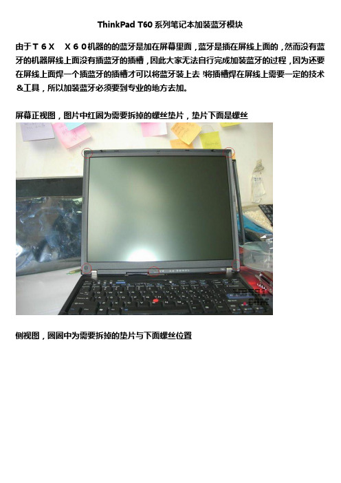
ThinkPad T60系列笔记本加装蓝牙模块
由于T6XX60机器的的蓝牙是加在屏幕里面,蓝牙是插在屏线上面的,然而没有蓝牙的机器屏线上面没有插蓝牙的插槽,因此大家无法自行完成加装蓝牙的过程,因为还要在屏线上面焊一个插蓝牙的插槽才可以将蓝牙装上去!将插槽焊在屏线上需要一定的技术&工具,所以加装蓝牙必须要到专业的地方去加。
屏幕正视图,图片中红圈为需要拆掉的螺丝垫片,垫片下面是螺丝
侧视图,圆圈中为需要拆掉的垫片与下面螺丝位置
同上,将正面与两侧的垫片与下面螺丝拆掉后,面筐就可以扣下来了
白圈屏轴,红蓝牙,绿屏线,蓝高压板,黄夜灯,
蓝牙大图,T6x同T4X蓝牙布局接口等不同,T6X蓝牙是在屏幕里面,屏幕A壳充当了蓝牙天线
红屏线,蓝高压条,深蓝蓝牙,黄无线天线,白夜灯,
蓝牙部分,大家可以看到螺丝将蓝牙拧在A壳上,这样A就充当了蓝牙天线了!
注意了,T6X,X60加装蓝牙的问题在于没有蓝牙的机器屏线上面没有白色的插曹,也就是说没办法将蓝牙插上去
再仔细看下,没有蓝牙的机器没有图片中白色的插槽。

CASSIA X2000蓝牙路由器快速入门指南版权所有 © 2020 北京桂花网科技有限公司I. 包装清单2. 抱杆安装箍 (2)3. 螺丝硅胶塞 (2)1. X2000蓝牙路由器 (1)4. 防水接头 (2)5. USB硅胶塞 (1)6. 安装支架 (1)7. 拆网线专用螺丝刀 (1)8. 安装螺丝和膨胀管 (2*4)9. 快速入门指南 (1)19II. 面板说明步骤2:用十字螺丝刀拧下螺丝,打开顶盖步骤3: 将4G上网卡插入USB接口步骤4: 安装顶盖,拧紧螺丝,塞上螺丝硅胶塞步骤3: 将USB延长线插入USB接口步骤2:使用一字螺丝刀拧下顶盖上的塞子(M20X1.5,请勿与ETH/PoE的塞子混淆)步骤4: 将USB延长线穿过顶盖上的孔,安装顶盖,将硅胶塞套在USB延长线上并塞入顶盖上的孔。
最后,将4G上网卡插入USB延长线的另一头注意:安装支架面向墙和杆的一侧比较锋利,请小心安装,以免伤到您的手。
壁挂安装抱杆安装壁挂安装抱杆安装3) 将X2000安装支架固定在平整的墙面上,或者使用抱箍拧在垂直的抱杆上4) 把X2000连接到安装支架上注意:为了拆下安装好的以太网线,请用X2000包装盒中提供的一字螺丝刀或其它小工具按下水晶头上的塑料卡舌,参见下图:5) 连接以太网线和PoE取下以太网接口塞(M22X1.5,请勿与顶盖上的塞子混淆),将以太网线穿过防水接头,把网线水晶头插入X2000的以太网接口,并按照a、b、c的顺序拧紧防水接头。
步骤c的力度应该小于步骤a的力度,避免损坏X2000的内部器件注意:拆除防水接头时,必须按照c、b、a的顺序,否则会损坏X2000内部器件7) 对于室外安装的X2000,建议在接地标志位置的螺钉上连接地线,确保X2000的安全支持蓝牙低功耗协议4.0/4.1/4.2/5.0集成Wi-Fi 802.11 a/b/g/n/ac, 支持2.4GHz and 5GHz ISM频段支持10/100 BASE-T以太网支持USB 2.0(可用于插3G/4G上网卡)可选外接蓝牙天线接口:50欧姆N型母头复位按钮:恢复出厂设置。

这款是最新免费版的usb蓝牙适配器万能通用驱动程序Widcomm 5.0.1.801 blt drive 版。
它可以驱动基本上所有蓝牙适配器,而且使用起来更加方便。
(详细的说明和使用安装方法下面都有,请放心!)下面请看清楚下面的说明,这款usb蓝牙适配器万能通用驱动程序非常地棒的!简单、方便、安全!强烈推荐!!压缩包里面包含usb蓝牙适配器万能通用驱动程序和破解文件,破解文件使用方法在文件内有说明。
请注意:安装前先删除C:\WINDOWS\INF\bth.inf 文件,或者剪贴到其它盘。
往事重提:以前安装了蓝牙适配器中自带的驱动程序和软件BlueSoleil,弄了半天才同步了一次,而且操作复杂,蓝牙一断开又不行了,感觉BlueSoleil不太稳定,有时候竟然还找不到手机。
后来,在上网查阅了许多资料终于搞定。
现在用的就是这个usb 蓝牙适配器万能通用驱动程序Widcomm 5.0.1.801 blt drive 版,非常地好用,同步很容易,此驱动大约有40多M。
下面是安装具体步骤:一、电脑设置:1、将蓝牙适配器插上后装好驱动,右击任务栏里面的Microsoft ActiveSync点击连接设置,如图1;2、将允许连接到以下其中一个端口前面的勾勾上,选COM 口3,按确定(不要连接)。
如图2二、手机设置:1、点击开始——设置——连接——蓝牙,调整为“可发现”,点击菜单——设备——菜单——新建,搜索蓝牙设备,应该很容易就找到电脑上的蓝牙适配器,然后下一步,输入密码(随便输,如“1”)这时电脑会弹出需要bluetooth通行密钥(图3),输入刚刚设定的密码如“1”,会弹出已请求bluetooth授权(图4)。
将“始终允许该设备访问该服务”的勾勾上后确定(图5)。
将手机上面Activesync的勾勾上后点完成。
2、将蓝牙设置为“打开”,现在设置com端口,菜单——COM端口——新建发送端口——菜单——新建发送端口,选择要添加的设备(刚刚搜索出来的计算机名字)下一步,这里的COM端口一般是6,然后是新建接收端口,一般是7。
前两次拆机后,看见了主板的蓝牙模块就一直思量着装个蓝牙。
淘宝花了55淘了个BT-183型号的蓝牙模块,2.0的,2.1比较贵。
说是原装的,支持蓝牙灯。
顺利装上了,很开心。
我就做了个教程,帮助需要的网友。
蓝牙模块(其实很小,也就两截小手指那么长)
寄到手的时候差点没找到东西,因为太小了,呵呵
先拔掉电源,拆掉电池。
只要拆下背面六颗螺丝即可(如图画圈的位置),不影响保修
拆完螺丝,翻过来用手指甲轻轻将面板掰开一个口子,然后就可以看见蓝牙线插口
只要用镊子把蓝牙线插上就可以了。
(注意先将连接线插到蓝牙模块上再插到主板上的接口上)别太用力,注意方向。
反了插不上。
最好用镊子,比较方便。
拧上螺丝,装上电池,开机。
Win 7下驱动自动会安装,其它系统自己下载驱动。
查看设备管理器,蓝牙装上了,可以正常使用了。
以后手机跟电脑传东西很方便了,还有就是弄个无线蓝牙鼠标,贼帅。

使用蓝牙的流程解说明1. 引言蓝牙是一种无线通信技术,用于在短距离范围内传输数据。
它在各种设备中广泛应用,如手机、平板电脑、蓝牙耳机等。
在本文档中,我们将解释如何使用蓝牙的流程。
我们将探讨蓝牙的设置、配对、连接和数据传输等。
2. 设置蓝牙在开始使用蓝牙之前,首先需要确保设备以及蓝牙功能已经启用,并进行合适的设置。
遵循以下步骤进行蓝牙设置:1.打开设备的设置菜单。
2.在设置菜单中查找并点击“蓝牙”选项。
3.在蓝牙设置页面上,找到并点击“启用蓝牙”按钮。
4.等待设备搜索附近的蓝牙设备。
3. 配对蓝牙设备一旦蓝牙已经处于启用状态,我们可以开始配对其他蓝牙设备。
根据以下步骤进行蓝牙设备配对:1.在蓝牙设置页面上,点击“搜索设备”按钮。
2.等待设备搜索附近的蓝牙设备。
3.选择所需的蓝牙设备名称。
4.如果需要,输入蓝牙设备的配对码。
5.点击“配对”按钮。
4. 连接蓝牙设备一旦配对成功,我们就可以连接到蓝牙设备上。
按照以下步骤进行蓝牙设备的连接:1.在蓝牙设置页面上,找到已配对的蓝牙设备列表。
2.选择所需的蓝牙设备名称。
3.点击“连接”按钮。
4.等待设备建立蓝牙连接。
5. 数据传输连接成功后,我们可以开始在设备之间传输数据。
以下是通过蓝牙传输数据的一些常见方式:•传输文件:在设备之间传输文件,如照片、音频文件等。
•传输文本:发送文本消息或笔记等。
•控制设备:通过蓝牙控制其他设备,如蓝牙音箱、蓝牙智能家居设备等。
6. 断开蓝牙连接在完成蓝牙通信后,我们应该及时断开蓝牙连接,以节省设备的电量。
按照以下步骤进行蓝牙断开连接:1.在蓝牙设置页面上,找到已连接的蓝牙设备列表。
2.选择所需的蓝牙设备名称。
3.点击“断开连接”按钮。
7. 结论使用蓝牙进行设备之间的通信变得越来越普遍,逐渐渗透到各个领域。
通过本文档,我们了解了使用蓝牙的流程,包括设置蓝牙、配对蓝牙设备、连接蓝牙设备、数据传输和断开蓝牙连接。
希望本文档能对您使用蓝牙有所帮助。
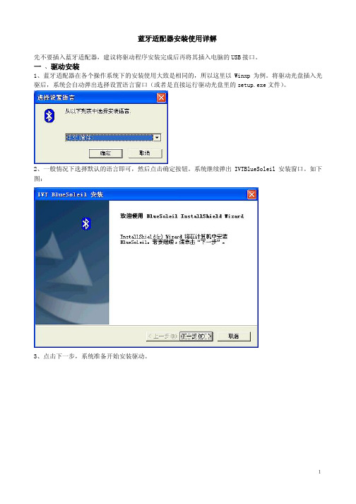
蓝牙适配器安装使用详解先不要插入蓝牙适配器,建议将驱动程序安装完成后再将其插入电脑的USB接口。
一、驱动安装1、蓝牙适配器在各个操作系统下的安装使用大致是相同的,所以这里以Winxp为例。
将驱动光盘插入光驱后,系统会自动弹出选择设置语言窗口(或者是直接运行驱动光盘里的setup.exe文件)。
2、一般情况下选择默认的语言即可,然后点击确定按钮。
系统继续弹出IVTBlueSoleil安装窗口。
如下图:3、点击下一步,系统准备开始安装驱动。
14、在弹出的窗口中点击是。
5、在弹出的新窗口中选择浏览,可以更改驱动程序存放的路径(如果不需要更改路径,则直接转到第7步)。
如下图:26、选择合适的路径,然后点击确定按钮。
系统回到选择目的地位置窗口。
7、继续点击下一步。
38、系统开始从驱动光盘里复制相关文件,这可能需要几分钟时间。
复制完毕后,系统会弹出如下图所示的窗口:9、选择是,立即重新启动计算机,然后点击完成。
(在98和winme系统里直接点击完成后,系统会自动重新启动计算机。
)10、重新启动完成后,在桌面上会弹出IVT CorporationBlueSoleil主窗口的窗口:411、在系统桌面和任务栏里都会多出新的蓝牙图标,如下图所示:56并且在网络适配器里也会多出一个蓝牙项目,如图:7三、蓝牙设备之间通讯的基本操作1、蓝牙手机与蓝牙适配器之间通讯(1)开启手机的蓝牙功能,然后打开蓝牙的主窗口,用鼠标左键点击主窗口中的球形图标,在球形体的"轨道"上会多出一个手机图标(这证明已经找到了蓝牙手机)。
如图:8(2)选中此手机图标,单击鼠标右键,如图:(3)在弹出的菜单中选择配对,系统会提示输入蓝牙口令窗口,如图:910(4)按照提示输入蓝牙口令(可随意输入),然后点击确定。
之后,手机方也会出现配对提示,输入配对码即可(要与前者口令一致)。
这样,两蓝牙设备之间就可以进行通讯了。
双击“轨道”上的手机图标,在主窗口里会出现如下图所示的五项蓝牙服务(分别为:蓝牙拨号网络服务,蓝牙串行端口服务,蓝牙文件传输服务,蓝牙信息同步服务,蓝牙对象交换服务,以下操作将对几种常用的服务进行详细说明。
Dell Precision 5820 T owerWi-Fi Bluetooth Module Installation GuideNotes, cautions, and warningsNOTE: A NOTE indicates important information that helps you make better use of your product.CAUTION: A CAUTION indicates either potential damage to hardware or loss of data and tells you how to avoid the problem.WARNING: A WARNING indicates a potential for property damage, personal injury, or death.© 2019 Dell Inc. or its subsidiaries. All rights reserved. Dell, EMC, and other trademarks are trademarks of Dell Inc. or its subsidiaries. Other trademarks may be trademarks of their respective owners.2019 - 02Rev. A001 Before you begin (4)Safety instructions (4)Before working inside your computer (4)Safety precautions (5)Electrostatic discharge—ESD protection (5)ESD field service kit (6)Transporting sensitive components (7)After working inside your computer (7)2 Wi-Fi Bluetooth (8)Wi-Fi Bluetooth Module installation kit (8)Installing the Wi-Fi Bluetooth Module for Precision 5820 Tower (8)3 Getting help (20)Contacting Dell (20)Contents3Before you begin Safety instructionsUse the following safety guidelines to protect your computer from potential damage and to ensure your personal safety. Unless otherwise noted, each procedure included in this document assumes that the following conditions exist:•You have read the safety information that shipped with your computer.•A component can be replaced or, if purchased separately, installed by performing the removal procedure in reverse order. WARNING: Disconnect all power sources before opening the computer cover or panels. After you finish working inside thecomputer, replace all covers, panels, and screws before connecting to the power source.WARNING: Before working inside your computer, read the safety information that shipped with your computer. For additional safety best practices information, see the Regulatory Compliance HomepageCAUTION: Many repairs may only be done by a certified service technician. You should only perform troubleshooting and simple repairs as authorized in your product documentation, or as directed by the online or telephone service and support team.Damage due to servicing that is not authorized by Dell is not covered by your warranty. Read and follow the safety instructions that came with the product.CAUTION: T o avoid electrostatic discharge, ground yourself by using a wrist grounding strap or by periodically touching an unpainted metal surface at the same time as touching a connector on the back of the computer.CAUTION: Handle components and cards with care. Do not touch the components or contacts on a card. Hold a card by its edges or by its metal mounting bracket. Hold a component such as a processor by its edges, not by its pins.CAUTION: When you disconnect a cable, pull on its connector or on its pull-tab, not on the cable itself. Some cables have connectors with locking tabs; if you are disconnecting this type of cable, press in on the locking tabs before you disconnect the cable. As you pull connectors apart, keep them evenly aligned to avoid bending any connector pins. Also, before you connect acable, ensure that both connectors are correctly oriented and aligned.NOTE: The color of your computer and certain components may appear differently than shown in this document.CAUTION: System will shut down if side covers are removed while the system is running. The system will not power on if the side cover is removed.Before working inside your computer1 Ensure that your work surface is flat and clean to prevent the computer cover from being scratched.2 Turn off your computer.3 Disconnect all network cables from the computer (if available).CAUTION: If your computer has an RJ45 port, disconnect the network cable by first unplugging the cable from yourcomputer.4 Disconnect your computer and all attached devices from their electrical outlets.5 Open the display.6 Press and hold the power button for few seconds, to ground the system board.CAUTION: To guard against electrical shock unplug your computer from the electrical outlet before performing Step #8.CAUTION: To avoid electrostatic discharge, ground yourself by using a wrist grounding strap or by periodically touchingan unpainted metal surface at the same time as touching a connector on the back of the computer.1 4Before you begin7 Remove any installed ExpressCards or Smart Cards from the appropriate slots.Safety precautionsThe safety precautions chapter details the primary steps to be taken before performing any disassembly instructions.Observe the following safety precautions before you perform any installation or break/fix procedures involving disassembly or reassembly:•Turn off the system and all attached peripherals.•Disconnect the system and all attached peripherals from AC power.•Disconnect all network cables, telephone, and telecommunications lines from the system.•Use an ESD field service kit when working inside any desktop to avoid electrostatic discharge (ESD) damage.•After removing any system component, carefully place the removed component on an anti-static mat.•Wear shoes with non-conductive rubber soles to reduce the chance of getting electrocuted.Standby powerDell products with standby power must be unplugged before you open the case. Systems that incorporate standby power are essentially powered while turned off. The internal power enables the system to be remotely turned on (wake on LAN) and suspended into a sleep mode and has other advanced power management features.Unplugging, pressing and holding the power button for 15 seconds should discharge residual power in the system board. . BondingBonding is a method for connecting two or more grounding conductors to the same electrical potential. This is done through the use of a field service electrostatic discharge (ESD) kit. When connecting a bonding wire, ensure that it is connected to bare metal and never to a painted or non-metal surface. The wrist strap should be secure and in full contact with your skin, and ensure that you remove all jewelry such as watches, bracelets, or rings prior to bonding yourself and the equipment.Electrostatic discharge—ESD protectionESD is a major concern when you handle electronic components, especially sensitive components such as expansion cards, processors, memory DIMMs, and system boards. Very slight charges can damage circuits in ways that may not be obvious, such as intermittent problems or a shortened product life span. As the industry pushes for lower power requirements and increased density, ESD protection is an increasing concern.Due to the increased density of semiconductors used in recent Dell products, the sensitivity to static damage is now higher than in previous Dell products. For this reason, some previously approved methods of handling parts are no longer applicable.Two recognized types of ESD damage are catastrophic and intermittent failures.•Catastrophic – Catastrophic failures represent approximately 20 percent of ESD-related failures. The damage causes an immediate and complete loss of device functionality. An example of catastrophic failure is a memory DIMM that has received a static shock and immediately generates a "No POST/No Video" symptom with a beep code emitted for missing or nonfunctional memory.•Intermittent – Intermittent failures represent approximately 80 percent of ESD-related failures. The high rate of intermittent failures means that most of the time when damage occurs, it is not immediately recognizable. The DIMM receives a static shock, but the tracing is merely weakened and does not immediately produce outward symptoms related to the damage. The weakened trace may take weeks or months to melt, and in the meantime may cause degradation of memory integrity, intermittent memory errors, etc.The more difficult type of damage to recognize and troubleshoot is the intermittent (also called latent or "walking wounded") failure. Perform the following steps to prevent ESD damage:Before you begin5•Use a wired ESD wrist strap that is properly grounded. The use of wireless anti-static straps is no longer allowed; they do not provide adequate protection. T ouching the chassis before handling parts does not ensure adequate ESD protection on parts with increased sensitivity to ESD damage.•Handle all static-sensitive components in a static-safe area. If possible, use anti-static floor pads and workbench pads.•When unpacking a static-sensitive component from its shipping carton, do not remove the component from the anti-static packing material until you are ready to install the component. Before unwrapping the anti-static packaging, ensure that you discharge static electricity from your body.•Before transporting a static-sensitive component, place it in an anti-static container or packaging.ESD field service kitThe unmonitored Field Service kit is the most commonly used service kit. Each Field Service kit includes three main components: anti-static mat, wrist strap, and bonding wire.Components of an ESD field service kitThe components of an ESD field service kit are:•Anti-Static Mat – The anti-static mat is dissipative and parts can be placed on it during service procedures. When using an anti-static mat, your wrist strap should be snug and the bonding wire should be connected to the mat and to any bare metal on the system being worked on. Once deployed properly, service parts can be removed from the ESD bag and placed directly on the mat. ESD-sensitive items are safe in your hand, on the ESD mat, in the system, or inside a bag.•Wrist Strap and Bonding Wire – The wrist strap and bonding wire can be either directly connected between your wrist and bare metal on the hardware if the ESD mat is not required, or connected to the anti-static mat to protect hardware that is temporarily placed on the mat. The physical connection of the wrist strap and bonding wire between your skin, the ESD mat, and the hardware is known as bonding. Use only Field Service kits with a wrist strap, mat, and bonding wire. Never use wireless wrist straps. Always be aware that the internal wires of a wrist strap are prone to damage from normal wear and tear, and must be checked regularly with a wrist strap tester in order to avoid accidental ESD hardware damage. It is recommended to test the wrist strap and bonding wire at least once per week.•ESD Wrist Strap Tester – The wires inside of an ESD strap are prone to damage over time. When using an unmonitored kit, it is a best practice to regularly test the strap prior to each service call, and at a minimum, test once per week. A wrist strap tester is the best method for doing this test. If you do not have your own wrist strap tester, check with your regional office to find out if they have one.T o perform the test, plug the wrist-strap's bonding-wire into the tester while it is strapped to your wrist and push the button to test. A green LED is lit if the test is successful; a red LED is lit and an alarm sounds if the test fails.•Insulator Elements – It is critical to keep ESD sensitive devices, such as plastic heat sink casings, away from internal parts that are insulators and often highly charged.•Working Environment – Before deploying the ESD Field Service kit, assess the situation at the customer location. For example, deploying the kit for a server environment is different than for a desktop or portable environment. Servers are typically installed in a rack within a data center; desktops or portables are typically placed on office desks or cubicles. Always look for a large open flat work area that is free of clutter and large enough to deploy the ESD kit with additional space to accommodate the type of system that is being repaired. The workspace should also be free of insulators that can cause an ESD event. On the work area, insulators such as Styrofoam and other plastics should always be moved at least 12 inches or 30 centimeters away from sensitive parts before physically handling any hardware components•ESD Packaging – All ESD-sensitive devices must be shipped and received in static-safe packaging. Metal, static-shielded bags are preferred. However, you should always return the damaged part using the same ESD bag and packaging that the new part arrived in.The ESD bag should be folded over and taped shut and all the same foam packing material should be used in the original box that the new part arrived in. ESD-sensitive devices should be removed from packaging only at an ESD-protected work surface, and parts should never be placed on top of the ESD bag because only the inside of the bag is shielded. Always place parts in your hand, on the ESD mat, in the system, or inside an anti-static bag.•Transporting Sensitive Components – When transporting ESD sensitive components such as replacement parts or parts to be returned to Dell, it is critical to place these parts in anti-static bags for safe transport.ESD protection summaryIt is recommended that all field service technicians use the traditional wired ESD grounding wrist strap and protective anti-static mat at all times when servicing Dell products. In addition, it is critical that technicians keep sensitive parts separate from all insulator parts while performing service and that they use anti-static bags for transporting sensitive components.6Before you beginTransporting sensitive componentsWhen transporting ESD sensitive components such as replacement parts or parts to be returned to Dell, it is critical to place these parts in anti-static bags for safe transport.Lifting equipmentAdhere to the following guidelines when lifting heavy weight equipment:CAUTION: Do not lift greater than 50 pounds. Always obtain additional resources or use a mechanical lifting device.1Get a firm balanced footing. Keep your feet apart for a stable base, and point your toes out.2Tighten stomach muscles. Abdominal muscles support your spine when you lift, offsetting the force of the load.3Lift with your legs, not your back.4Keep the load close. The closer it is to your spine, the less force it exerts on your back.5Keep your back upright, whether lifting or setting down the load. Do not add the weight of your body to the load. Avoid twisting your body and back.6Follow the same techniques in reverse to set the load down.After working inside your computerAfter you complete any replacement procedure, ensure that you connect external devices, cards, and cables before turning on your computer.CAUTION: T o avoid damage to the computer, use only the battery designed for this particular Dell computer. Do not use batteries designed for other Dell computers.1 Connect any external devices, such as a port replicator or media base, and replace any cards, such as an ExpressCard.2 Connect any telephone or network cables to your computer.CAUTION: To connect a network cable, first plug the cable into the network device and then plug it into thecomputer.3 Connect your computer and all attached devices to their electrical outlets.4 Turn on your computer.Before you begin7Wi-Fi BluetoothWi-Fi Bluetooth Module installation kitThe following components are required to install the Wi-Fi/ Bluetooth (BT) module:1Wi-Fi/BT PCIe adapter card 2Wi-Fi card screw 3Wi-Fi card bracket 4Wi-Fi card 5Wi-Fi/BT PCIe adapter card cable 6External antenna7Plastic cover Installing the Wi-Fi Bluetooth Module for Precision 5820 Tower1Follow the procedure in before working inside your computer .2 To install the Wi-Fi card into the Wi-Fi/Bluetooth (BT) PCIe adapter card:aAlign and insert the Wi-Fi card into the slot on the Wi-Fi/BT PCIe adapter card [1].bConnect the antenna cables to the Wi-Fi card [2].cAlign the Wi-Fi card bracket on the Wi-Fi card [3].d Tighten the single screw (M2x2.5) to secure both the Wi-Fi card bracket and Wi-Fi card to the Wi-Fi/BT PCIe adapter card [4].28Wi-Fi BluetoothWi-Fi Bluetooth94 To remove the side cover:a Press the latch.10Wi-Fi BluetoothWi-Fi Bluetooth115 To remove the PCIe card holder:•If full length cards are installed, you will need to remove these cards before removing the holder.•If MegaRAID 9460 is installed, disconnect the Super CAP from the card before removing the PCIe card holder from the system.a Disconnect the two power cables from the cable slot in the PCIe holder [1].b Press the PCIe holder securing clip and slide the holder [2] out of the chassis.12Wi-Fi Bluetooth6 To remove the filler bracket:a Press and rotate the PCI latch backward [1] to unlock the filler bracket.b Remove the filler bracket from the slot on the system [2].Wi-Fi Bluetooth1314Wi-Fi Bluetooth8 To connect the Wi-Fi/BT PCIe adapter card cable:a Lock both the PCI latch brackets forward on the filler bracket to secure the Wi-Fi/BT PCIe adapter card to the system board [1].b Route the Wi-Fi/BT PCIe adapter card cable through to the routing channels on the system [2].c Connect other end of the Wi-Fi/BT PCIe adapter card cable socket to the connector on the system board [3].Wi-Fi Bluetooth159 To install the PCIe holder:a Align and place the PCIe holder to the system chassis [1]. Then, press the holder back until it clicks to the system.b Connect the two power cables to the cable slots in the holder [2].•If the MegaRAID 9460 was removed, please connect the Super CAP back to the card.•Reinstall the full length cards if they were removed.16Wi-Fi BluetoothWi-Fi Bluetooth1711 To install the external antenna:a Pass the external antenna cables through the openings on the plastic cover [1].b Fasten antenna cables to Wi-Fi/BT PCIe adapter card [2].c Tighten the single screw to secure the plastic cover to the PCI panel [3].18Wi-Fi BluetoothWi-Fi Bluetooth19Getting helpContacting DellNOTE: If you do not have an active Internet connection, you can find contact information on your purchase invoice, packing slip, bill, or Dell product catalog.Dell provides several online and telephone-based support and service options. Availability varies by country and product, and some services may not be available in your area. T o contact Dell for sales, technical support, or customer service issues:1Go to /support.2Select your support category.3Verify your country or region in the Choose a Country/Region drop-down list at the bottom of the page.4 Select the appropriate service or support link based on your need.320Getting help。
Win7下的蓝牙驱动安装方法如果找不到IVT的win7正版软件,以及笔记本内置的蓝牙安装的Widcomm软件,可使用该方法安装蓝牙。
使用IVT软件,和使用笔记本内置蓝牙,请参考另外两份文档。
当然,xp系统也可以按照该方法设置,不必使用第三方软件。
只是使用第三方软件更方便一些。
插上蓝牙适配器后,win7自动安装驱动。
点下角蓝牙图标,右键-》添加设备:选中手机图标,点“下一步”:这个时候手机提示输入验证码,输入上图的“88752027”,win7开始安装驱动,安装的过程中,手机会多次提示是否接受pc的连接请求,要在一定的时间内点“是”,请不要超时。
(本文档的最后将介绍如何取消手机的这个提示。
)双击win7右下角的蓝牙图标,出现如下图示:双击手机图标,出现如下图示:上图中选中通过Bluetooth链接的标准调制解调器,点“属性”,出现如下图示:这个com5,就是手机连接的端口(设备管理的调制解调器项也可以查看到该窗口)。
点“查询调制解调器”,OK后即可使用该端口。
客户管理软件中的通讯设置窗口中,手机端口,填写该端口号即可。
说明:上述操作只需要第二次使用时设置一下,以后不必每次都设置。
但是如果更换了手机,或者蓝牙插到电脑上的USB接口更换了位置,则需要重新操作一下。
前者按照上述的步骤操作即可,后者查看一下调制解调器的端口即可。
NOKIA的pc套件使用该蓝牙的方法:建议使用数据线连接套件,使用蓝牙的连接方法需要经过多次的实践才能熟悉,而用数据线则简单的多,连接过程中手机也不会多次的提示是否接受pc连接请求。
Pc套件的菜单:设置-》管理连接:出现如下界面:将“蓝牙”勾选上。
关闭。
Pc套件的主界面,点“单击此处可连接手机”:点下一步:选中“蓝牙连接”,点下一步:选中手机,点下一步,ok后,pc套件即可通过蓝牙连接手机。
备注:连接过程中手机会多次提示是否接受pc连接,点是。
NOKIA手机蓝牙连接电脑,手机每次提示是否接受pc的连接请求,取消方法:进入NOKIA手机的蓝牙设置(功能表->连接功能->蓝牙),按手机键盘上的滚球杆的右方向,显示该手机的配对的设备,然后按“选项”,选“设为授权设备”即可。
主板上的WiFi和蓝牙模块的选择和安装在选择和安装主板上的WiFi和蓝牙模块时,有几个关键因素需要考虑。
这些因素将决定您的计算机系统是否能够实现无线网络连接和蓝牙设备连接的功能,并影响其性能和稳定性。
本文将介绍如何选择适合的WiFi和蓝牙模块,并讲解安装步骤和注意事项。
选择WiFi模块WiFi模块是实现无线网络连接的关键组件之一。
在选择WiFi模块时,您需要考虑以下几点:1. 支持的协议:不同的WiFi模块支持不同的无线协议,如802.11n、802.11ac等。
您应该选择支持最新无线协议的模块,以获得更高的网络速度和更好的稳定性。
2. 频率范围:WiFi模块可以在2.4GHz和5GHz频段工作。
2.4GHz频段能够提供更远的传输距离,但5GHz频段速度更快。
选择时应根据实际需求来定。
3. 天线选型:WiFi模块的天线类型有内置天线和外置天线两种。
内置天线结构紧凑,安装简单,但信号覆盖范围有限;外置天线则能提供更远的信号传输距离。
根据使用环境和需求选择适合的天线类型。
选择蓝牙模块蓝牙模块提供了无线连接外部设备的功能,如耳机、键盘、鼠标等。
在选择蓝牙模块时,需要以下几个方面:1. 蓝牙版本:蓝牙技术不断更新,目前最新的是蓝牙5.0版本,它提供更快的传输速度和更低的功耗。
如果您的设备支持蓝牙5.0,那么选择支持该版本的模块将是一个不错的选择。
2. 芯片厂商:蓝牙芯片的质量和稳定性直接影响到连接效果。
知名的芯片制造商如Broadcom、Qualcomm等在市场上有良好的口碑,选择这些品牌的产品能够提供更好的用户体验。
安装WiFi和蓝牙模块一般情况下,主板上已经预留了安装WiFi和蓝牙模块的插槽。
在进行安装之前,确保主板上的电源已被切断,并遵循以下步骤:1. 找到主板上的插槽:根据主板的说明书,找到用于安装WiFi和蓝牙模块的插槽。
通常位于主板背面的PCIe插槽或M.2插槽。
2. 安装天线:如果您选择的WiFi模块有外置天线,将天线连接到相应的接口上。
笔记本怎么安装蓝牙驱动程序
我们在使用笔记本电脑的时候,如果遇见需要安装一些驱动程序的问题,比如蓝牙驱动程序的安装。
对于这种情况,小编觉得可以尝试在设备管理器中进行对蓝牙驱动的检测和安装。
一般来说只要是电脑支出蓝牙设备,系统是会自带有蓝牙驱动的,所以如果有驱动的话可以选择更新驱动。
详细步骤就来看看小编是怎么做的吧~
笔记本怎么安装蓝牙驱动程序解决步骤:
1.电脑桌面,右键,点击
2.然后点击
3.然后展开
4.然后鼠标右键,点击
5.选择一种方式更新驱动,更新完驱动就大功告成了。