伺服电机外文文献翻译
- 格式:docx
- 大小:30.04 KB
- 文档页数:18
机械专业英语词汇中英文对照翻译一览表陶瓷ceramics合成纤维synthetic fibre电化学腐蚀electrochemical corrosion车架automotive chassis悬架suspension转向器redirector变速器speed changer板料冲压sheet metal parts孔加工spot facing machining车间workshop工程技术人员engineer气动夹紧pneuma lock数学模型mathematical model画法几何descriptive geometry机械制图Mechanical drawing投影projection视图view剖视图profile chart标准件standard component零件图part drawing装配图assembly drawing尺寸标注size marking技术要求technical requirements刚度rigidity内力internal force位移displacement截面section疲劳极限fatigue limit断裂fracture塑性变形plastic distortion脆性材料brittleness material刚度准则rigidity criterion垫圈washer垫片spacer直齿圆柱齿轮straight toothed spur gear 斜齿圆柱齿轮helical-spur gear直齿锥齿轮straight bevel gear运动简图kinematic sketch齿轮齿条pinion and rack蜗杆蜗轮worm and worm gear虚约束passive constraint曲柄crank摇杆racker凸轮cams共轭曲线conjugate curve范成法generation method定义域definitional domain值域range导数\\微分differential coefficient求导derivation定积分definite integral不定积分indefinite integral曲率curvature偏微分partial differential毛坯rough游标卡尺slide caliper千分尺micrometer calipers攻丝tap二阶行列式second order determinant 逆矩阵inverse matrix线性方程组linear equations概率probability随机变量random variable排列组合permutation and combination 气体状态方程equation of state of gas动能kinetic energy势能potential energy机械能守恒conservation of mechanical energy动量momentum桁架truss轴线axes余子式cofactor逻辑电路logic circuit触发器flip-flop脉冲波形pulse shape数模digital analogy液压传动机构fluid drive mechanism机械零件mechanical parts淬火冷却quench淬火hardening回火tempering调质hardening and tempering磨粒abrasive grain结合剂bonding agent砂轮grinding wheel后角clearance angle龙门刨削planing主轴spindle主轴箱headstock卡盘chuck加工中心machining center 车刀lathe tool车床lathe钻削镗削bore车削turning磨床grinder基准benchmark钳工locksmith锻forge压模stamping焊weld拉床broaching machine拉孔broaching装配assembling铸造found流体动力学fluid dynamics流体力学fluid mechanics加工machining液压hydraulic pressure切线tangent机电一体化mechanotronics mechanical-electrical integration气压air pressure pneumatic pressure稳定性stability介质medium液压驱动泵fluid clutch液压泵hydraulic pump阀门valve失效invalidation强度intensity载荷load应力stress安全系数safty factor可靠性reliability螺纹thread螺旋helix键spline销pin滚动轴承rolling bearing滑动轴承sliding bearing弹簧spring制动器arrester brake十字结联轴节crosshead联轴器coupling链chain皮带strap精加工finish machining粗加工rough machining变速箱体gearbox casing腐蚀rust氧化oxidation磨损wear耐用度durability随机信号random signal离散信号discrete signal超声传感器ultrasonic sensor 集成电路integrate circuit挡板orifice plate残余应力residual stress套筒sleeve扭力torsion冷加工cold machining电动机electromotor汽缸cylinder过盈配合interference fit热加工hotwork摄像头CCD camera倒角rounding chamfer优化设计optimal design工业造型设计industrial moulding design有限元finite element滚齿hobbing插齿gear shaping伺服电机actuating motor铣床milling machine钻床drill machine镗床boring machine步进电机stepper motor丝杠screw rod导轨lead rail组件subassembly可编程序逻辑控制器Programmable Logic Controller PLC 电火花加工electric spark machining电火花线切割加工electrical discharge wire - cutting 相图phase diagram热处理heat treatment固态相变solid state phase changes有色金属nonferrous metal陶瓷ceramics合成纤维synthetic fibre电化学腐蚀electrochemical corrosion车架automotive chassis悬架suspension转向器redirector变速器speed changer板料冲压sheet metal parts孔加工spot facing machining车间workshop工程技术人员engineer气动夹紧pneuma lock数学模型mathematical model画法几何descriptive geometry机械制图Mechanical drawing投影projection视图view剖视图profile chart标准件standard component零件图part drawing装配图assembly drawing尺寸标注size marking技术要求technical requirements刚度rigidity内力internal force位移displacement截面section疲劳极限fatigue limit断裂fracture塑性变形plastic distortion脆性材料brittleness material刚度准则rigidity criterion垫圈washer垫片spacer直齿圆柱齿轮straight toothed spur gear 斜齿圆柱齿轮helical-spur gear直齿锥齿轮straight bevel gear运动简图kinematic sketch齿轮齿条pinion and rack蜗杆蜗轮worm and worm gear虚约束passive constraint曲柄crank摇杆racker凸轮cams共轭曲线conjugate curve范成法generation method定义域definitional domain值域range导数\\微分differential coefficient求导derivation定积分definite integral不定积分indefinite integral曲率curvature偏微分partial differential毛坯rough游标卡尺slide caliper千分尺micrometer calipers攻丝tap二阶行列式second order determinant 逆矩阵inverse matrix线性方程组linear equations概率probability随机变量random variable排列组合permutation and combination气体状态方程equation of state of gas动能kinetic energy势能potential energy机械能守恒conservation of mechanical energy 动量momentum桁架truss轴线axes余子式cofactor逻辑电路logic circuit触发器flip-flop脉冲波形pulse shape数模digital analogy液压传动机构fluid drive mechanism机械零件mechanical parts淬火冷却quench淬火hardening回火tempering调质hardening and tempering磨粒abrasive grain结合剂bonding agent砂轮grinding wheel Assembly line 组装线Layout 布置图Conveyer 流水线物料板Rivet table 拉钉机Rivet gun 拉钉枪Screw driver 起子Pneumatic screw driver 气动起子worktable 工作桌OOBA 开箱检查fit together 组装在一起fasten 锁紧(螺丝)fixture 夹具(治具)pallet 栈板barcode 条码barcode scanner 条码扫描器fuse together 熔合fuse machine热熔机repair修理operator作业员QC品管supervisor 课长ME 制造工程师MT 制造生技cosmetic inspect 外观检查inner parts inspect 内部检查thumb screw 大头螺丝lbs. inch 镑、英寸EMI gasket 导电条front plate 前板rear plate 后板chassis 基座bezel panel 面板power button 电源按键reset button 重置键Hi-pot test of SPS 高源高压测试Voltage switch of SPS 电源电压接拉键sheet metal parts 冲件plastic parts 塑胶件SOP 制造作业程序material check list 物料检查表work cell 工作间trolley 台车carton 纸箱sub-line 支线left fork 叉车personnel resource department 人力资源部production department生产部门planning department企划部QC Section品管科stamping factory冲压厂painting factory烤漆厂molding factory成型厂common equipment常用设备uncoiler and straightener整平机punching machine 冲床robot机械手hydraulic machine油压机lathe车床planer |plein|刨床miller铣床grinder磨床linear cutting线切割electrical sparkle电火花welder电焊机staker=reviting machine铆合机position职务president董事长general manager总经理special assistant manager特助factory director厂长department director部长deputy manager | =vice manager副理section supervisor课长deputy section supervisor =vice section superisor副课长group leader/supervisor组长line supervisor线长assistant manager助理to move, to carry, to handle搬运be put in storage入库pack packing包装to apply oil擦油to file burr 锉毛刺final inspection终检to connect material接料to reverse material 翻料wet station沾湿台Tiana天那水cleaning cloth抹布to load material上料to unload material卸料to return material/stock to退料scraped |\\'skr?pid|报废scrape ..v.刮;削deficient purchase来料不良manufacture procedure制程deficient manufacturing procedure制程不良oxidation |\\' ksi\\'dei?n|氧化scratch刮伤dents压痕defective upsiding down抽芽不良defective to staking铆合不良embedded lump镶块feeding is not in place送料不到位stamping-missing漏冲production capacity生产力education and training教育与训练proposal improvement提案改善spare parts=buffer备件forklift叉车trailer=long vehicle拖板车compound die合模die locker锁模器pressure plate=plate pinch压板bolt螺栓administration/general affairs dept总务部automatic screwdriver电动启子thickness gauge厚薄规gauge(or jig)治具power wire电源线buzzle蜂鸣器defective product label不良标签identifying sheet list标示单location地点present members出席人员subject主题conclusion结论decision items决议事项responsible department负责单位pre-fixed finishing date预定完成日approved by / checked by / prepared by核准/审核/承办PCE assembly production schedule sheet PCE组装厂生产排配表model机锺work order工令revision版次remark备注production control confirmation生产确认checked by初审approved by核准department部门stock age analysis sheet 库存货龄分析表on-hand inventory现有库存available material良品可使用obsolete material良品已呆滞to be inspected or reworked 待验或重工total合计cause description原因说明part number/ P/N 料号type形态item/group/class类别quality品质prepared by制表notes说明year-end physical inventory difference analysis sheet 年终盘点差异分析表physical inventory盘点数量physical count quantity帐面数量difference quantity差异量cause analysis原因分析raw materials原料materials物料finished product成品semi-finished product半成品packing materials包材good product/accepted goods/ accepted parts/good parts 良品defective product/non-good parts不良品disposed goods处理品warehouse/hub仓库on way location在途仓oversea location海外仓spare parts physical inventory list备品盘点清单spare molds location模具备品仓skid/pallet栈板tox machine自铆机wire EDM线割EDM放电机coil stock卷料sheet stock片料tolerance工差score=groove压线cam block滑块pilot导正筒trim剪外边pierce剪内边drag form压锻差pocket for the punch head挂钩槽slug hole废料孔feature die公母模expansion dwg展开图radius半径shim(wedge)楔子torch-flame cut火焰切割set screw止付螺丝form block折刀stop pin定位销round pierce punch=die button圆冲子shape punch=die insert异形子stock locater block定位块under cut=scrap chopper清角active plate活动板baffle plate挡块cover plate盖板male die公模female die母模groove punch压线冲子air-cushion eject-rod气垫顶杆spring-box eject-plate弹簧箱顶板bushing block衬套insert 入块club car高尔夫球车capability能力parameter参数factor系数phosphate皮膜化成viscosity涂料粘度alkalidipping脱脂main manifold主集流脉bezel斜视规blanking穿落模dejecting顶固模demagnetization去磁;消磁high-speed transmission高速传递heat dissipation热传rack上料degrease脱脂rinse水洗alkaline etch龄咬desmut剥黑膜D.I. rinse纯水次Chromate铬酸处理Anodize阳性处理seal封孔revision版次part number/P/N料号good products良品scraped products报放心品defective products不良品finished products成品disposed products处理品barcode条码flow chart流程表单assembly组装stamping冲压molding成型spare parts=buffer备品coordinate座标dismantle the die折模auxiliary fuction辅助功能poly-line多义线heater band 加热片thermocouple热电偶sand blasting喷沙grit 砂砾derusting machine除锈机degate打浇口dryer烘干机induction感应induction light感应光response=reaction=interaction感应ram连杆edge finder巡边器concave凸convex凹short射料不足nick缺口speck瑕??shine亮班splay 银纹gas mark焦痕delamination起鳞cold slug冷块blush 导色gouge沟槽;凿槽satin texture段面咬花witness line证示线patent专利grit沙砾granule=peuet=grain细粒grit maker抽粒机cushion缓冲magnalium镁铝合金magnesium镁金metal plate钣金lathe车mill锉plane刨grind磨drill铝boring镗blinster气泡fillet镶;嵌边through-hole form通孔形式voller pin formality滚针形式cam driver铡楔shank摸柄crank shaft曲柄轴augular offset角度偏差velocity速度production tempo生产进度现状torque扭矩spline=the multiple keys花键quenching淬火tempering回火annealing退火carbonization碳化tungsten high speed steel钨高速的moly high speed steel钼高速的organic solvent有机溶剂bracket小磁导liaison联络单volatile挥发性resistance电阻ion离子titrator滴定仪beacon警示灯coolant冷却液crusher破碎机阿基米德蜗杆Archimedes worm安全系数safety factor; factor of safety安全载荷safe load凹面、凹度concavity扳手wrench板簧flat leaf spring半圆键woodruff key变形deformation摆杆oscillating bar摆动从动件oscillating follower摆动从动件凸轮机构cam with oscillating follower 摆动导杆机构oscillating guide-bar mechanism 摆线齿轮cycloidal gear摆线齿形cycloidal tooth profile摆线运动规律cycloidal motion摆线针轮cycloidal-pin wheel包角angle of contact保持架cage背对背安装back-to-back arrangement背锥back cone ;normal cone背锥角back angle背锥距back cone distance比例尺scale比热容specific heat capacity闭式链closed kinematic chain闭链机构closed chain mechanism臂部arm变频器frequency converters变频调速frequency control of motor speed 变速speed change变速齿轮change gear change wheel变位齿轮modified gear变位系数modification coefficient标准齿轮standard gear标准直齿轮standard spur gear表面质量系数superficial mass factor表面传热系数surface coefficient of heat transfer 表面粗糙度surface roughness并联式组合combination in parallel并联机构parallel mechanism并联组合机构parallel combined mechanism并行工程concurrent engineering并行设计concurred design, CD不平衡相位phase angle of unbalance不平衡imbalance (or unbalance)不平衡量amount of unbalance不完全齿轮机构intermittent gearing波发生器wave generator波数number of waves补偿compensation参数化设计parameterization design, PD残余应力residual stress操纵及控制装置operation control device槽轮Geneva wheel槽轮机构Geneva mechanism ;Maltese cross 槽数Geneva numerate槽凸轮groove cam侧隙backlash差动轮系differential gear train差动螺旋机构differential screw mechanism差速器differential常用机构conventional mechanism; mechanism in common use车床lathe承载量系数bearing capacity factor承载能力bearing capacity成对安装paired mounting尺寸系列dimension series齿槽tooth space齿槽宽spacewidth齿侧间隙backlash齿顶高addendum齿顶圆addendum circle齿根高dedendum齿根圆dedendum circle齿厚tooth thickness齿距circular pitch齿宽face width齿廓tooth profile齿廓曲线tooth curve齿轮gear齿轮变速箱speed-changing gear boxes齿轮齿条机构pinion and rack齿轮插刀pinion cutter; pinion-shaped shaper cutter 齿轮滚刀hob ,hobbing cutter齿轮机构gear齿轮轮坯blank齿轮传动系pinion unit齿轮联轴器gear coupling齿条传动rack gear齿数tooth number齿数比gear ratio齿条rack齿条插刀rack cutter; rack-shaped shaper cutter齿形链、无声链silent chain齿形系数form factor齿式棘轮机构tooth ratchet mechanism插齿机gear shaper重合点coincident points重合度contact ratio冲床punch传动比transmission ratio, speed ratio传动装置gearing; transmission gear传动系统driven system传动角transmission angle传动轴transmission shaft串联式组合combination in series串联式组合机构series combined mechanism 串级调速cascade speed control创新innovation creation创新设计creation design垂直载荷、法向载荷normal load唇形橡胶密封lip rubber seal磁流体轴承magnetic fluid bearing从动带轮driven pulley从动件driven link, follower从动件平底宽度width of flat-face从动件停歇follower dwell从动件运动规律follower motion从动轮driven gear粗线bold line粗牙螺纹coarse thread大齿轮gear wheel打包机packer打滑slipping带传动belt driving带轮belt pulley带式制动器band brake单列轴承single row bearing单向推力轴承single-direction thrust bearing单万向联轴节single universal joint单位矢量unit vector当量齿轮equivalent spur gear; virtual gear当量齿数equivalent teeth number; virtual number of teeth 当量摩擦系数equivalent coefficient of friction当量载荷equivalent load刀具cutter导数derivative倒角chamfer导热性conduction of heat导程lead导程角lead angle等加等减速运动规律parabolic motion; constant acceleration and deceleration motion等速运动规律uniform motion; constant velocity motion等径凸轮conjugate yoke radial cam等宽凸轮constant-breadth cam等效构件equivalent link等效力equivalent force等效力矩equivalent moment of force等效量equivalent等效质量equivalent mass等效转动惯量equivalent moment of inertia等效动力学模型dynamically equivalent model底座chassis低副lower pair点划线chain dotted line(疲劳)点蚀pitting垫圈gasket垫片密封gasket seal碟形弹簧belleville spring顶隙bottom clearance定轴轮系ordinary gear train; gear train with fixed axes 动力学dynamics动密封kinematical seal动能dynamic energy动力粘度dynamic viscosity动力润滑dynamic lubrication动平衡dynamic balance动平衡机dynamic balancing machine动态特性dynamic characteristics动态分析设计dynamic analysis design动压力dynamic reaction动载荷dynamic load端面transverse plane端面参数transverse parameters端面齿距transverse circular pitch端面齿廓transverse tooth profile端面重合度transverse contact ratio端面模数transverse module端面压力角transverse pressure angle锻造forge对称循环应力symmetry circulating stress对心滚子从动件radial (or in-line ) roller follower对心直动从动件radial (or in-line ) translating follower对心移动从动件radial reciprocating follower对心曲柄滑块机构in-line slider-crank (or crank-slider) mechanism多列轴承multi-row bearing多楔带poly V-belt多项式运动规律polynomial motion多质量转子rotor with several masses惰轮idle gear额定寿命rating life额定载荷load ratingII 级杆组dyad发生线generating line发生面generating plane法面normal plane法面参数normal parameters法面齿距normal circular pitch法面模数normal module法面压力角normal pressure angle法向齿距normal pitch法向齿廓normal tooth profile法向直廓蜗杆straight sided normal worm法向力normal force反馈式组合feedback combining反向运动学inverse ( or backward) kinematics 反转法kinematic inversion反正切Arctan范成法generating cutting仿形法form cutting方案设计、概念设计concept design, CD防振装置shockproof device飞轮flywheel飞轮矩moment of flywheel非标准齿轮nonstandard gear非接触式密封non-contact seal非周期性速度波动aperiodic speed fluctuation非圆齿轮non-circular gear粉末合金powder metallurgy分度线reference line; standard pitch line分度圆reference circle; standard (cutting) pitch circle 分度圆柱导程角lead angle at reference cylinder分度圆柱螺旋角helix angle at reference cylinder分母denominator分子numerator分度圆锥reference cone; standard pitch cone分析法analytical method封闭差动轮系planetary differential复合铰链compound hinge复合式组合compound combining复合轮系compound (or combined) gear train 复合平带compound flat belt复合应力combined stress复式螺旋机构Compound screw mechanism复杂机构 complex mechanism杆组Assur group干涉interference刚度系数stiffness coefficient刚轮rigid circular spline钢丝软轴wire soft shaft刚体导引机构body guidance mechanism刚性冲击rigid impulse (shock)刚性转子rigid rotor刚性轴承rigid bearing刚性联轴器rigid coupling高度系列height series高速带high speed belt高副higher pair格拉晓夫定理Grashoff`s law根切undercutting公称直径nominal diameter高度系列height series功work工况系数application factor工艺设计technological design工作循环图working cycle diagram工作机构operation mechanism工作载荷external loads工作空间working space工作应力working stress工作阻力effective resistance工作阻力矩effective resistance moment 公法线common normal line公共约束general constraint公制齿轮metric gears功率power功能分析设计function analyses design 共轭齿廓conjugate profiles共轭凸轮conjugate cam构件link鼓风机blower固定构件fixed link; frame固体润滑剂solid lubricant关节型操作器jointed manipulator惯性力inertia force惯性力矩moment of inertia ,shaking moment 惯性力平衡balance of shaking force惯性力完全平衡full balance of shaking force惯性力部分平衡partial balance of shaking force 惯性主矩resultant moment of inertia惯性主失resultant vector of inertia冠轮crown gear广义机构generation mechanism广义坐标generalized coordinate轨迹生成path generation轨迹发生器path generator滚刀hob滚道raceway滚动体rolling element滚动轴承rolling bearing滚动轴承代号rolling bearing identification code 滚针needle roller滚针轴承needle roller bearing滚子roller滚子轴承roller bearing滚子半径radius of roller滚子从动件roller follower滚子链roller chain滚子链联轴器double roller chain coupling 滚珠丝杆ball screw滚柱式单向超越离合器roller clutch过度切割undercutting函数发生器function generator函数生成function generation含油轴承oil bearing耗油量oil consumption耗油量系数oil consumption factor赫兹公式H. Hertz equation合成弯矩resultant bending moment合力resultant force合力矩resultant moment of force黑箱black box横坐标abscissa互换性齿轮interchangeable gears花键spline滑键、导键feather key滑动轴承sliding bearing滑动率sliding ratio滑块slider环面蜗杆toroid helicoids worm环形弹簧annular spring缓冲装置shocks; shock-absorber灰铸铁grey cast iron回程return回转体平衡balance of rotors混合轮系 compound gear train积分integrate机电一体化系统设计mechanical-electrical integration system design机构mechanism机构分析analysis of mechanism机构平衡balance of mechanism机构学mechanism机构运动设计kinematic design of mechanism机构运动简图kinematic sketch of mechanism机构综合synthesis of mechanism机构组成constitution of mechanism机架frame, fixed link机架变换kinematic inversion机器machine机器人robot机器人操作器manipulator机器人学robotics技术过程technique process技术经济评价technical and economic evaluation 技术系统technique system机械machinery机械创新设计mechanical creation design, MCD 机械系统设计mechanical system design, MSD 机械动力分析dynamic analysis of machinery机械动力设计dynamic design of machinery机械动力学dynamics of machinery机械的现代设计modern machine design机械系统mechanical system机械利益mechanical advantage机械平衡balance of machinery机械手manipulator机械设计machine design; mechanical design机械特性mechanical behavior机械调速mechanical speed governors机械效率mechanical efficiency机械原理theory of machines and mechanisms机械运转不均匀系数coefficient of speed fluctuation机械无级变速mechanical stepless speed changes基础机构fundamental mechanism基本额定寿命basic rating life基于实例设计case-based design,CBD基圆base circle基圆半径radius of base circle基圆齿距base pitch基圆压力角pressure angle of base circle基圆柱base cylinder基圆锥base cone急回机构quick-return mechanism急回特性quick-return characteristics急回系数advance-to return-time ratio急回运动quick-return motion棘轮ratchet棘轮机构ratchet mechanism棘爪pawl极限位置extreme (or limiting) position极位夹角crank angle between extreme (or limiting) positions计算机辅助设计computer aided design, CAD计算机辅助制造computer aided manufacturing, CAM计算机集成制造系统computer integrated manufacturing system, CIMS计算力矩factored moment; calculation moment计算弯矩calculated bending moment加权系数weighting efficient加速度acceleration加速度分析acceleration analysis加速度曲线acceleration diagram尖点pointing; cusp尖底从动件knife-edge follower间隙backlash间歇运动机构intermittent motion mechanism减速比reduction ratio减速齿轮、减速装置reduction gear减速器speed reducer减摩性anti-friction quality渐开螺旋面involute helicoid渐开线involute渐开线齿廓involute profile渐开线齿轮involute gear渐开线发生线generating line of involute渐开线方程involute equation渐开线函数involute function渐开线蜗杆involute worm渐开线压力角pressure angle of involute渐开线花键involute spline简谐运动simple harmonic motion键key键槽keyway交变应力repeated stress交变载荷repeated fluctuating load交叉带传动cross-belt drive交错轴斜齿轮crossed helical gears胶合scoring角加速度angular acceleration角速度angular velocity角速比angular velocity ratio角接触球轴承angular contact ball bearing角接触推力轴承angular contact thrust bearing 角接触向心轴承angular contact radial bearing 角接触轴承angular contact bearing铰链、枢纽hinge校正平面correcting plane接触应力contact stress接触式密封contact seal阶梯轴multi-diameter shaft结构structure结构设计structural design截面section节点pitch point节距circular pitch; pitch of teeth节线pitch line节圆pitch circle节圆齿厚thickness on pitch circle节圆直径pitch diameter节圆锥pitch cone节圆锥角pitch cone angle解析设计analytical design紧边tight-side紧固件fastener径节diametral pitch径向radial direction径向当量动载荷dynamic equivalent radial load径向当量静载荷static equivalent radial load径向基本额定动载荷basic dynamic radial load rating径向基本额定静载荷basic static radial load tating径向接触轴承radial contact bearing径向平面radial plane径向游隙radial internal clearance径向载荷radial load径向载荷系数radial load factor径向间隙clearance静力static force静平衡static balance静载荷static load静密封static seal局部自由度passive degree of freedom矩阵matrix矩形螺纹square threaded form锯齿形螺纹buttress thread form矩形牙嵌式离合器square-jaw positive-contact clutch 绝对尺寸系数absolute dimensional factor绝对运动absolute motion绝对速度absolute velocity均衡装置load balancing mechanism抗压强度compression strength开口传动open-belt drive开式链open kinematic chain开链机构open chain mechanism可靠度degree of reliability可靠性reliability可靠性设计reliability design, RD空气弹簧air spring空间机构spatial mechanism空间连杆机构spatial linkage空间凸轮机构spatial cam空间运动副spatial kinematic pair空间运动链spatial kinematic chain 空转idle宽度系列width series框图block diagram雷诺方程Reynolds‘s equation离心力centrifugal force离心应力centrifugal stress离合器clutch离心密封centrifugal seal理论廓线pitch curve理论啮合线theoretical line of action 隶属度membership力force力多边形force polygon力封闭型凸轮机构force-drive (or force-closed) cam mechanism力矩moment力平衡equilibrium力偶couple力偶矩moment of couple连杆connecting rod, coupler连杆机构linkage连杆曲线coupler-curve连心线line of centers链chain链传动装置chain gearing链轮sprocket sprocket-wheel sprocket gear chain wheel联组V 带tight-up V belt联轴器coupling shaft coupling两维凸轮two-dimensional cam临界转速critical speed六杆机构six-bar linkage龙门刨床double Haas planer轮坯blank。
毕业论文外文文献翻译译文题目:INTEGRATION OF MACHINERY外文资料翻译资料来源:文章名:INTEGRATION OF MACHINERY 《Digital Image Processing》书刊名:作者:Y. Torres J. J. Pavón I. Nieto and J. A.Rodríguez章节:2.4 INTEGRATION OF MACHINERYINTEGRATION OF MACHINERY (From ELECTRICAL AND MACHINERY INDUSTRY)ABSTRACT Machinery was the modern science and technology development inevitable resultthis article has summarized the integration of machinery technology basic outlineand the development background .Summarized the domestic and foreign integration ofmachinery technology present situation has analyzed the integration of machinerytechnology trend of development. Key word:integration of machinery ,technology,present situation ,productt,echnique of manufacture ,trend of development 0. Introduction modern science and technology unceasing development impelleddifferent discipline intersecting enormously with the seepage has caused the projectdomain technological revolution and the transformation .In mechanical engineeringdomain because the microelectronic technology and the computer technology rapiddevelopment and forms to the mechanical industry seepage the integration of machinerycaused the mechanical industry the technical structure the product organizationthe function and the constitution the production method and the management systemhas had the huge change caused the industrial production to enter into quottheintegration of machineryquot by quotthe machinery electrificationquot for the characteristicdevelopment phase. 1. Integration of machinery outline integration of machinery is refers in theorganization new owner function the power function in the information processingfunction and the control function introduces the electronic technology unifies thesystem the mechanism and the computerization design and the software whichconstitutes always to call. The integration of machinery development also has becomeone to have until now own system new discipline not only develops along with thescience and technology but also entrusts with the new content .But its basiccharacteristic may summarize is: The integration of machinery is embarks from thesystem viewpoint synthesis community technologies and so on utilization mechanicaltechnology microelectronic technology automatic control technology computertechnology information technology sensing observation and control technologyelectric power electronic technology connection technology information conversiontechnology as well as software programming technology according to the systemfunction goal and the optimized organization goal reasonable disposition and thelayout various functions unit in multi-purpose high grade redundant reliable inthe low energy consumption significance realize the specific function value andcauses the overall system optimization the systems engineering technology .From thisproduces functional system then becomes an integration of machinery systematic orthe integration of machinery product. Therefore quotintegration of machineryquot coveringquottechnologyquot and quotproductquot two aspects .Only is the integration of machinerytechnology is based on the above community technology organic fusion one kind ofcomprehensivetechnology but is not mechanical technical the microelectronictechnology as well as other new technical simple combination pieces together .Thisis the integration of machinery and the machinery adds the machinery electrificationwhich the electricity forms in the concept basic difference .The mechanicalengineering technology has the merely technical to develop the machineryelectrification still was the traditional machinery its main function still wasreplaces with the enlargement physical strength .But after develops the integrationof machinery micro electron installment besides may substitute for certainmechanical parts the original function but also can entrust with many new functionslike the automatic detection the automatic reduction information demonstrate therecord the automatic control and the control automatic diagnosis and the protectionautomatically and so on .Not only namely the integration of machinery product ishumans hand and body extending humans sense organ and the brains look has theintellectualized characteristic is the integration of machinery and the machineryelectrification distinguishes in the function essence. 2. Integration of machinery development condition integration of machinerydevelopment may divide into 3 stages roughly.20th century 60s before for the firststage this stage is called the initial stage .In this time the people determinationnot on own initiative uses the electronic technology the preliminary achievement toconsummate the mechanical product the performance .Specially in Second World Warperiod the war has stimulated the mechanical product and the electronic technologyunion these mechanical and electrical union military technology postwar transferscivilly to postwar economical restoration positive function .Developed and thedevelopment at that time generally speaking also is at the spontaneouscondition .Because at that time the electronic technology development not yetachieved certain level mechanical technical and electronic technology union alsonot impossible widespread and thorough development already developed the productwas also unable to promote massively. The 20th century 7080 ages for the second stagemay be called the vigorous development stage .This time the computer technologythe control technology the communication development has laid the technology basefor the integration of machinery development . Large-scale ultra large scaleintegrated circuit and microcomputer swift and violent development has provided thefull material base for the integration of machinery development .This timecharacteristic is :①A mechatronics word first generally is accepted in Japanprobably obtains the quite widespread acknowledgment to 1980s last stages in theworldwide scale ②The integration of machinery technology and the product obtainedthe enormous development ③The various countries start to the integration ofmachinery technology and the product give the very big attention and the support.1990s later periods started the integration of machinery technology the new stagewhich makes great strides forward to the intellectualized direction the integrationof machinery enters the thorough development time .At the same time optics thecommunication and so on entered the integration of machinery processes thetechnology also zhan to appear tiny in the integration of machinery the footappeared the light integration of machinery and the micro integration of machineryand so on the new branch On the other hand to the integration ofmachinery systemmodeling design the analysis and the integrated method the integration ofmachinery discipline system and the trend of development has all conducted thethorough research .At the same time because the hugeprogress which domains and so on artificial intelligence technology neural networktechnology and optical fiber technology obtain opened the development vast worldfor the integration of machinery technology .These research will urge theintegration of machinery further to establish the integrity the foundation and formsthe integrity gradually the scientific system. Our country is only then starts fromthe beginning of 1980s in this aspect to study with the application .The State Councilhad been established the integration of machinery leading group and lists as quot863plansquot this technology .When formulated quot95quot the plan and in 2010 developed thesummary had considered fully on international the influence which and possiblybrought from this about the integration of machinery technology developmenttrend .Many universities colleges and institutes the development facility and somelarge and middle scale enterprises have done the massive work to this technicaldevelopment and the application does not yield certain result but and so on theadvanced countries compared with Japan still has the suitable disparity. 3. Integration of machinery trend of development integrations of machinery arethe collection machinery the electron optics the control the computer theinformation and so on the multi-disciplinary overlapping syntheses its developmentand the progress rely on and promote the correlation technology development and theprogress .Therefore the integration of machinery main development direction is asfollows: 3.1 Intellectualized intellectualizations are 21st century integration ofmachinery technological development important development directions .Theartificial intelligence obtains day by day in the integration of machineryconstructors research takes the robot and the numerical control engine bedintellectualization is the important application .Here said quottheintellectualizationquot is to the machine behavior description is in the control theoryfoundation the absorption artificial intelligence the operations research thecomputer science the fuzzy mathematics the psychology the physiology and the chaosdynamics and so on the new thought the new method simulate the human intelligenceenable it to have abilities and so on judgment inference logical thinkingindependent decision-making obtains the higher control goal in order to .Indeedenable the integration of machinery product to have with the human identicalintelligence is not impossible also is nonessential .But the high performancethe high speed microprocessor enable the integration of machinery product to havepreliminary intelligent or humans partial intelligences then is completelypossible and essential. In the modern manufacture process the information has become the controlmanufacture industry the determining factor moreover is the most active actuationfactor .Enhances the manufacture system information-handling capacity to become themodern manufacture science development a key point .As a result of the manufacturesystem information organization and structure multi-level makes the information thegain the integration and the fusion presents draws up the character informationmeasuremulti-dimensional as well as information organizations multi-level .In themanufacture information structural model manufacture information uniform restraintdissemination processing and magnanimous data aspects and so on manufacture knowledgelibrary management all also wait for further break through. Each kind of artificial intelligence tool and the computation intelligence methodpromoted the manufacture intelligence development in the manufacture widespreadapplication .A kind based on the biological evolution algorithm computationintelligent agent in includes thescheduling problem in the combination optimization solution area of technologyreceives the more and more universal attention hopefully completes the combinationoptimization question when the manufacture the solution speed and the solutionprecision aspect breaks through the question scale in pairs the restriction .Themanufacture intelligence also displays in: The intelligent dispatch the intelligentdesign the intelligent processing the robot study the intelligent control theintelligent craft plan the intelligent diagnosis and so on are various These question key breakthrough may form the product innovation the basicresearch system. Between 2 modern mechanical engineering front science differentscience overlapping fusion will have the new science accumulation the economicaldevelopment and societys progress has had the new request and the expectation tothe science and technology thus will form the front science .The front science alsohas solved and between the solution scientific question border area .The front sciencehas the obvious time domain the domain and the dynamic characteristic .The projectfront science distinguished in the general basic science important characteristicis it has covered the key science and technology question which the project actualappeared. Manufacture system is a complex large-scale system for satisfies the manufacturesystem agility the fast response and fast reorganization ability must profit fromthe information science the life sciences and the social sciences and so on themulti-disciplinary research results the exploration manufacture system newarchitecture the manufacture pattern and the manufacture system effectiveoperational mechanism .Makes the system optimization the organizational structureand the good movement condition is makes the system modeling the simulation andthe optimized essential target .Not only the manufacture system new architecture tomakes the enterprise the agility and may reorganize ability to the demand responseability to have the vital significance moreover to made the enterprise first floorproduction equipment the flexibility and may dynamic reorganization ability set ahigher request .The biological manufacture view more and more many is introduced themanufacture system satisfies the manufacture system new request. The study organizes and circulates method and technique of complicated systemfrom the biological phenomenon is a valid exit which will solve many hard nut tocracks that manufacturing industry face from now on currently .Imitating to livingwhat manufacturing point is mimicry living creature organ of from the organizationfrom match more from growth with from evolution etc. function structure and circulatemode of a kind of manufacturing system and manufacturing process. The manufacturing drives in the mechanism under continuously by ones ownperfect raise on organizing structure and circulating modeand thus to adapt theprocess ofwith ability for the environment .For from descend but the last productproceed together a design and make a craft rules the auto of the distance born producesystem of dynamic state reorganization and product and manufacturing the system tendautomatically excellent provided theories foundation and carry out acondition .Imitate to living a manufacturing to belong to manufacturing science andlife science ofquotthe far good luck is miscellaneous to hand overquot it will produceto the manufacturing industry for 21 centuries huge of influence .机电一体化摘要机电一体化是现代科学技术发展的必然结果本文简述了机电一体化技术的基本概要和发展背景。
(机械制造行业)机械专业中英文对照翻译大全机械专业英语词汇中英文对照翻译一览表陶瓷ceramics合成纤维synthetic fibre电化学腐蚀electrochemical corrosion车架automotive chassis悬架suspension转向器redirector变速器speed changer板料冲压sheet metal parts孔加工spot facing machining车间workshop工程技术人员engineer气动夹紧pneuma lock数学模型mathematical model画法几何descriptive geometry机械制图Mechanical drawing投影projection视图view剖视图profile chart标准件standard component零件图part drawing装配图assembly drawing尺寸标注size marking技术要求technical requirements刚度rigidity内力internal force位移displacement截面section疲劳极限fatigue limit断裂fracture塑性变形plastic distortion脆性材料brittleness material刚度准则rigidity criterion垫圈washer垫片spacer直齿圆柱齿轮straight toothed spur gear 斜齿圆柱齿轮helical-spur gear直齿锥齿轮straight bevel gear运动简图kinematic sketch齿轮齿条pinion and rack蜗杆蜗轮worm and worm gear虚约束passive constraint曲柄crank摇杆racker凸轮cams共轭曲线conjugate curve范成法generation method定义域definitional domain值域range导数\\微分differential coefficient求导derivation定积分definite integral不定积分indefinite integral曲率curvature偏微分partial differential毛坯rough游标卡尺slide caliper千分尺micrometer calipers攻丝tap二阶行列式second order determinant逆矩阵inverse matrix线性方程组linear equations概率probability随机变量random variable排列组合permutation and combination气体状态方程equation of state of gas动能kinetic energy势能potential energy机械能守恒conservation of mechanical energy动量momentum桁架truss轴线axes余子式cofactor逻辑电路logic circuit触发器flip-flop脉冲波形pulse shape数模digital analogy液压传动机构fluid drive mechanism机械零件mechanical parts淬火冷却quench淬火hardening回火tempering调质hardening and tempering磨粒abrasive grain结合剂bonding agent砂轮grinding wheel后角clearance angle龙门刨削planing主轴spindle主轴箱headstock卡盘chuck加工中心machining center 车刀lathe tool车床lathe钻削镗削bore车削turning磨床grinder基准benchmark钳工locksmith锻forge压模stamping焊weld拉床broaching machine 拉孔broaching装配assembling铸造found流体动力学fluid dynamics 流体力学fluid mechanics加工machining液压hydraulic pressure切线tangent机电一体化mechanotronics mechanical-electrical integration气压air pressure pneumatic pressure稳定性stability介质medium液压驱动泵fluid clutch液压泵hydraulic pump阀门valve失效invalidation强度intensity载荷load应力stress安全系数safty factor可靠性reliability螺纹thread螺旋helix键spline销pin滚动轴承rolling bearing滑动轴承sliding bearing弹簧spring制动器arrester brake十字结联轴节crosshead联轴器coupling链chain皮带strap精加工finish machining粗加工rough machining变速箱体gearbox casing腐蚀rust氧化oxidation磨损wear耐用度durability随机信号random signal离散信号discrete signal超声传感器ultrasonic sensor 集成电路integrate circuit挡板orifice plate残余应力residual stress套筒sleeve扭力torsion冷加工cold machining电动机electromotor汽缸cylinder过盈配合interference fit热加工hotwork摄像头CCD camera倒角rounding chamfer优化设计optimal design工业造型设计industrial moulding design有限元finite element滚齿hobbing插齿gear shaping伺服电机actuating motor铣床milling machine钻床drill machine镗床boring machine步进电机stepper motor丝杠screw rod导轨lead rail组件subassembly可编程序逻辑控制器Programmable Logic Controller PLC 电火花加工electric spark machining电火花线切割加工electrical discharge wire - cutting 相图phase diagram热处理heat treatment固态相变solid state phase changes有色金属nonferrous metal陶瓷ceramics合成纤维synthetic fibre电化学腐蚀electrochemical corrosion车架automotive chassis悬架suspension转向器redirector变速器speed changer板料冲压sheet metal parts孔加工spot facing machining车间workshop工程技术人员engineer气动夹紧pneuma lock数学模型mathematical model画法几何descriptive geometry机械制图Mechanical drawing投影projection视图view剖视图profile chart标准件standard component零件图part drawing装配图assembly drawing尺寸标注size marking技术要求technical requirements刚度rigidity内力internal force位移displacement截面section疲劳极限fatigue limit断裂fracture塑性变形plastic distortion脆性材料brittleness material刚度准则rigidity criterion垫圈washer垫片spacer直齿圆柱齿轮straight toothed spur gear 斜齿圆柱齿轮helical-spur gear直齿锥齿轮straight bevel gear运动简图kinematic sketch齿轮齿条pinion and rack蜗杆蜗轮worm and worm gear虚约束passive constraint曲柄crank摇杆racker凸轮cams共轭曲线conjugate curve范成法generation method定义域definitional domain值域range导数\\微分differential coefficient求导derivation定积分definite integral不定积分indefinite integral曲率curvature偏微分partial differential毛坯rough游标卡尺slide caliper千分尺micrometer calipers攻丝tap二阶行列式second order determinant 逆矩阵inverse matrix线性方程组linear equations概率probability随机变量random variable排列组合permutation and combination气体状态方程equation of state of gas动能kinetic energy势能potential energy机械能守恒conservation of mechanical energy 动量momentum桁架truss轴线axes余子式cofactor逻辑电路logic circuit触发器flip-flop脉冲波形pulse shape数模digital analogy液压传动机构fluid drive mechanism机械零件mechanical parts淬火冷却quench淬火hardening回火tempering调质hardening and tempering磨粒abrasive grain结合剂bonding agent砂轮grinding wheelAssembly line 组装线Layout 布置图Conveyer 流水线物料板Rivet table 拉钉机Rivet gun 拉钉枪Screw driver 起子Pneumatic screw driver 气动起子worktable 工作桌OOBA 开箱检查fit together 组装在一起fasten 锁紧(螺丝)fixture 夹具(治具)pallet 栈板barcode 条码barcode scanner 条码扫描器fuse together 熔合fuse machine热熔机repair修理operator作业员QC品管supervisor 课长ME 制造工程师MT 制造生技cosmetic inspect 外观检查inner parts inspect 内部检查thumb screw 大头螺丝lbs. inch 镑、英寸EMI gasket 导电条front plate 前板rear plate 后板chassis 基座bezel panel 面板power button 电源按键reset button 重置键Hi-pot test of SPS 高源高压测试Voltage switch of SPS 电源电压接拉键sheet metal parts 冲件plastic parts 塑胶件SOP 制造作业程序material check list 物料检查表work cell 工作间trolley 台车carton 纸箱sub-line 支线left fork 叉车personnel resource department 人力资源部production department生产部门planning department企划部QC Section品管科stamping factory冲压厂painting factory烤漆厂molding factory成型厂common equipment常用设备uncoiler and straightener整平机punching machine 冲床robot机械手hydraulic machine油压机lathe车床planer |plein|刨床miller铣床grinder磨床linear cutting线切割electrical sparkle电火花welder电焊机staker=reviting machine铆合机position职务president董事长general manager总经理special assistant manager特助factory director厂长department director部长deputy manager | =vice manager副理section supervisor课长deputy section supervisor =vice section superisor副课长group leader/supervisor组长line supervisor线长assistant manager助理to move, to carry, to handle搬运be put in storage入库pack packing包装to apply oil擦油to file burr 锉毛刺final inspection终检to connect material接料to reverse material 翻料wet station沾湿台Tiana天那水cleaning cloth抹布to load material上料to unload material卸料to return material/stock to退料scraped |\\'skr?pid|报废scrape ..v.刮;削deficient purchase来料不良manufacture procedure制程deficient manufacturing procedure制程不良oxidation |\\' ksi\\'dei?n|氧化scratch刮伤dents压痕defective upsiding down抽芽不良defective to staking铆合不良embedded lump镶块feeding is not in place送料不到位stamping-missing漏冲production capacity生产力education and training教育与训练proposal improvement提案改善spare parts=buffer备件forklift叉车trailer=long vehicle拖板车compound die合模die locker锁模器pressure plate=plate pinch压板bolt螺栓administration/general affairs dept总务部automatic screwdriver电动启子thickness gauge厚薄规gauge(or jig)治具power wire电源线buzzle蜂鸣器defective product label不良标签identifying sheet list标示单location地点present members出席人员subject主题conclusion结论decision items决议事项responsible department负责单位pre-fixed finishing date预定完成日approved by / checked by / prepared by核准/审核/承办PCE assembly production schedule sheet PCE组装厂生产排配表model机锺work order工令revision版次remark备注production control confirmation生产确认checked by初审approved by核准department部门stock age analysis sheet 库存货龄分析表on-hand inventory现有库存available material良品可使用obsolete material良品已呆滞to be inspected or reworked 待验或重工total合计cause description原因说明part number/ P/N 料号type形态item/group/class类别quality品质prepared by制表notes说明year-end physical inventory difference analysis sheet 年终盘点差异分析表physical inventory盘点数量physical count quantity帐面数量difference quantity差异量cause analysis原因分析raw materials原料materials物料finished product成品semi-finished product半成品packing materials包材good product/accepted goods/ accepted parts/good parts良品defective product/non-good parts不良品disposed goods处理品warehouse/hub仓库on way location在途仓oversea location海外仓spare parts physical inventory list备品盘点清单spare molds location模具备品仓skid/pallet栈板tox machine自铆机wire EDM线割EDM放电机coil stock卷料sheet stock片料tolerance工差score=groove压线cam block滑块pilot导正筒trim剪外边pierce剪内边drag form压锻差pocket for the punch head挂钩槽slug hole废料孔feature die公母模expansion dwg展开图radius半径shim(wedge)楔子torch-flame cut火焰切割set screw止付螺丝form block折刀stop pin定位销round pierce punch=die button圆冲子shape punch=die insert异形子stock locater block定位块under cut=scrap chopper清角active plate活动板baffle plate挡块cover plate盖板male die公模female die母模groove punch压线冲子air-cushion eject-rod气垫顶杆spring-box eject-plate弹簧箱顶板bushing block衬套insert 入块club car高尔夫球车capability能力parameter参数factor系数phosphate皮膜化成viscosity涂料粘度alkalidipping脱脂main manifold主集流脉bezel斜视规blanking穿落模dejecting顶固模demagnetization去磁;消磁high-speed transmission高速传递heat dissipation热传rack上料degrease脱脂rinse水洗alkaline etch龄咬desmut剥黑膜D.I. rinse纯水次Chromate铬酸处理Anodize阳性处理seal封孔revision版次part number/P/N料号good products良品scraped products报放心品defective products不良品finished products成品disposed products处理品barcode条码flow chart流程表单assembly组装stamping冲压molding成型spare parts=buffer备品coordinate座标dismantle the die折模auxiliary fuction辅助功能poly-line多义线heater band 加热片thermocouple热电偶sand blasting喷沙grit 砂砾derusting machine除锈机degate打浇口dryer烘干机induction感应induction light感应光response=reaction=interaction感应ram连杆edge finder巡边器concave凸convex凹short射料不足nick缺口speck瑕??shine亮班splay 银纹gas mark焦痕delamination起鳞cold slug冷块blush 导色gouge沟槽;凿槽satin texture段面咬花witness line证示线patent专利grit沙砾granule=peuet=grain细粒grit maker抽粒机cushion缓冲magnalium镁铝合金magnesium镁金metal plate钣金lathe车mill锉plane刨grind磨drill铝boring镗blinster气泡fillet镶;嵌边through-hole form通孔形式voller pin formality滚针形式cam driver铡楔shank摸柄crank shaft曲柄轴augular offset角度偏差velocity速度production tempo生产进度现状torque扭矩spline=the multiple keys花键quenching淬火tempering回火annealing退火carbonization碳化tungsten high speed steel钨高速的moly high speed steel钼高速的organic solvent有机溶剂bracket小磁导liaison联络单volatile挥发性resistance电阻ion离子titrator滴定仪beacon警示灯coolant冷却液crusher破碎机阿基米德蜗杆Archimedes worm安全系数safety factor; factor of safety安全载荷safe load凹面、凹度concavity扳手wrench板簧flat leaf spring半圆键woodruff key变形deformation摆杆oscillating bar摆动从动件oscillating follower摆动从动件凸轮机构cam with oscillating follower 摆动导杆机构oscillating guide-bar mechanism 摆线齿轮cycloidal gear摆线齿形cycloidal tooth profile摆线运动规律cycloidal motion摆线针轮cycloidal-pin wheel包角angle of contact保持架cage背对背安装back-to-back arrangement背锥back cone ;normal cone背锥角back angle背锥距back cone distance比例尺scale比热容specific heat capacity闭式链closed kinematic chain闭链机构closed chain mechanism臂部arm变频器frequency converters变频调速frequency control of motor speed 变速speed change变速齿轮change gear change wheel变位齿轮modified gear变位系数modification coefficient标准齿轮standard gear标准直齿轮standard spur gear表面质量系数superficial mass factor表面传热系数surface coefficient of heat transfer 表面粗糙度surface roughness并联式组合combination in parallel并联机构parallel mechanism并联组合机构parallel combined mechanism并行工程concurrent engineering并行设计concurred design, CD不平衡相位phase angle of unbalance不平衡imbalance (or unbalance)不平衡量amount of unbalance不完全齿轮机构intermittent gearing波发生器wave generator波数number of waves补偿compensation参数化设计parameterization design, PD残余应力residual stress操纵及控制装置operation control device槽轮Geneva wheel槽轮机构Geneva mechanism ;Maltese cross 槽数Geneva numerate槽凸轮groove cam侧隙backlash差动轮系differential gear train差动螺旋机构differential screw mechanism差速器differential常用机构conventional mechanism; mechanism in common use车床lathe承载量系数bearing capacity factor承载能力bearing capacity成对安装paired mounting尺寸系列dimension series齿槽tooth space齿槽宽spacewidth齿侧间隙backlash齿顶高addendum齿顶圆addendum circle齿根高dedendum齿根圆dedendum circle齿厚tooth thickness齿距circular pitch齿宽face width齿廓tooth profile齿廓曲线tooth curve齿轮gear齿轮变速箱speed-changing gear boxes齿轮齿条机构pinion and rack齿轮插刀pinion cutter; pinion-shaped shaper cutter 齿轮滚刀hob ,hobbing cutter齿轮机构gear齿轮轮坯blank齿轮传动系pinion unit齿轮联轴器gear coupling齿条传动rack gear齿数tooth number齿数比gear ratio齿条rack齿条插刀rack cutter; rack-shaped shaper cutter齿形链、无声链silent chain齿形系数form factor齿式棘轮机构tooth ratchet mechanism插齿机gear shaper重合点coincident points重合度contact ratio冲床punch传动比transmission ratio, speed ratio传动装置gearing; transmission gear传动系统driven system传动角transmission angle传动轴transmission shaft串联式组合combination in series串联式组合机构series combined mechanism 串级调速cascade speed control创新innovation creation创新设计creation design垂直载荷、法向载荷normal load唇形橡胶密封lip rubber seal磁流体轴承magnetic fluid bearing从动带轮driven pulley从动件driven link, follower从动件平底宽度width of flat-face从动件停歇follower dwell从动件运动规律follower motion从动轮driven gear粗线bold line粗牙螺纹coarse thread大齿轮gear wheel打包机packer打滑slipping带传动belt driving带轮belt pulley带式制动器band brake单列轴承single row bearing单向推力轴承single-direction thrust bearing单万向联轴节single universal joint单位矢量unit vector当量齿轮equivalent spur gear; virtual gear当量齿数equivalent teeth number; virtual number of teeth当量摩擦系数equivalent coefficient of friction当量载荷equivalent load刀具cutter导数derivative倒角chamfer导热性conduction of heat导程lead导程角lead angle等加等减速运动规律parabolic motion; constant acceleration and deceleration motion等速运动规律uniform motion; constant velocity motion等径凸轮conjugate yoke radial cam等宽凸轮constant-breadth cam等效构件equivalent link等效力equivalent force等效力矩equivalent moment of force等效量equivalent等效质量equivalent mass等效转动惯量equivalent moment of inertia等效动力学模型dynamically equivalent model底座chassis低副lower pair点划线chain dotted line(疲劳)点蚀pitting垫圈gasket垫片密封gasket seal碟形弹簧belleville spring顶隙bottom clearance定轴轮系ordinary gear train; gear train with fixed axes 动力学dynamics动密封kinematical seal动能dynamic energy动力粘度dynamic viscosity动力润滑dynamic lubrication动平衡dynamic balance动平衡机dynamic balancing machine动态特性dynamic characteristics动态分析设计dynamic analysis design动压力dynamic reaction动载荷dynamic load端面transverse plane端面参数transverse parameters端面齿距transverse circular pitch端面齿廓transverse tooth profile端面重合度transverse contact ratio端面模数transverse module端面压力角transverse pressure angle锻造forge对称循环应力symmetry circulating stress对心滚子从动件radial (or in-line ) roller follower对心直动从动件radial (or in-line ) translating follower对心移动从动件radial reciprocating follower对心曲柄滑块机构in-line slider-crank (or crank-slider) mechanism多列轴承multi-row bearing多楔带poly V-belt多项式运动规律polynomial motion多质量转子rotor with several masses惰轮idle gear额定寿命rating life额定载荷load ratingII 级杆组dyad发生线generating line发生面generating plane法面normal plane法面参数normal parameters法面齿距normal circular pitch法面模数normal module法面压力角normal pressure angle法向齿距normal pitch法向齿廓normal tooth profile法向直廓蜗杆straight sided normal worm法向力normal force反馈式组合feedback combining反向运动学inverse ( or backward) kinematics 反转法kinematic inversion反正切Arctan范成法generating cutting仿形法form cutting方案设计、概念设计concept design, CD防振装置shockproof device飞轮flywheel飞轮矩moment of flywheel非标准齿轮nonstandard gear非接触式密封non-contact seal非周期性速度波动aperiodic speed fluctuation非圆齿轮non-circular gear粉末合金powder metallurgy分度线reference line; standard pitch line分度圆reference circle; standard (cutting) pitch circle 分度圆柱导程角lead angle at reference cylinder分度圆柱螺旋角helix angle at reference cylinder分母denominator分子numerator分度圆锥reference cone; standard pitch cone分析法analytical method封闭差动轮系planetary differential复合铰链compound hinge复合式组合compound combining复合轮系compound (or combined) gear train复合平带compound flat belt复合应力combined stress复式螺旋机构Compound screw mechanism 复杂机构complex mechanism杆组Assur group干涉interference刚度系数stiffness coefficient刚轮rigid circular spline钢丝软轴wire soft shaft刚体导引机构body guidance mechanism 刚性冲击rigid impulse (shock)刚性转子rigid rotor刚性轴承rigid bearing刚性联轴器rigid coupling高度系列height series高速带high speed belt高副higher pair格拉晓夫定理Grashoff`s law根切undercutting公称直径nominal diameter高度系列height series功work工况系数application factor工艺设计technological design工作循环图working cycle diagram工作机构operation mechanism工作载荷external loads工作空间working space工作应力working stress工作阻力effective resistance工作阻力矩effective resistance moment 公法线common normal line公共约束general constraint公制齿轮metric gears功率power功能分析设计function analyses design 共轭齿廓conjugate profiles共轭凸轮conjugate cam构件link鼓风机blower固定构件fixed link; frame固体润滑剂solid lubricant关节型操作器jointed manipulator惯性力inertia force惯性力矩moment of inertia ,shaking moment 惯性力平衡balance of shaking force惯性力完全平衡full balance of shaking force惯性力部分平衡partial balance of shaking force 惯性主矩resultant moment of inertia惯性主失resultant vector of inertia冠轮crown gear广义机构generation mechanism广义坐标generalized coordinate轨迹生成path generation轨迹发生器path generator滚刀hob滚道raceway滚动体rolling element滚动轴承rolling bearing滚动轴承代号rolling bearing identification code 滚针needle roller滚针轴承needle roller bearing滚子roller滚子轴承roller bearing滚子半径radius of roller滚子从动件roller follower滚子链roller chain滚子链联轴器double roller chain coupling 滚珠丝杆ball screw滚柱式单向超越离合器roller clutch过度切割undercutting函数发生器function generator函数生成function generation含油轴承oil bearing耗油量oil consumption耗油量系数oil consumption factor赫兹公式H. Hertz equation合成弯矩resultant bending moment合力resultant force合力矩resultant moment of force黑箱black box横坐标abscissa互换性齿轮interchangeable gears花键spline滑键、导键feather key滑动轴承sliding bearing滑动率sliding ratio滑块slider环面蜗杆toroid helicoids worm环形弹簧annular spring缓冲装置shocks; shock-absorber灰铸铁grey cast iron回程return回转体平衡balance of rotors混合轮系compound gear train积分integrate机电一体化系统设计mechanical-electrical integration system design机构mechanism机构分析analysis of mechanism机构平衡balance of mechanism机构学mechanism机构运动设计kinematic design of mechanism机构运动简图kinematic sketch of mechanism机构综合synthesis of mechanism机构组成constitution of mechanism机架frame, fixed link机架变换kinematic inversion机器machine机器人robot机器人操作器manipulator机器人学robotics技术过程technique process技术经济评价technical and economic evaluation 技术系统technique system机械machinery机械创新设计mechanical creation design, MCD机械系统设计mechanical system design, MSD机械动力分析dynamic analysis of machinery机械动力设计dynamic design of machinery机械动力学dynamics of machinery机械的现代设计modern machine design机械系统mechanical system机械利益mechanical advantage机械平衡balance of machinery机械手manipulator机械设计machine design; mechanical design机械特性mechanical behavior机械调速mechanical speed governors机械效率mechanical efficiency机械原理theory of machines and mechanisms机械运转不均匀系数coefficient of speed fluctuation机械无级变速mechanical stepless speed changes基础机构fundamental mechanism基本额定寿命basic rating life基于实例设计case-based design,CBD基圆base circle基圆半径radius of base circle基圆齿距base pitch基圆压力角pressure angle of base circle基圆柱base cylinder基圆锥base cone急回机构quick-return mechanism急回特性quick-return characteristics急回系数advance-to return-time ratio急回运动quick-return motion棘轮ratchet棘轮机构ratchet mechanism棘爪pawl极限位置extreme (or limiting) position极位夹角crank angle between extreme (or limiting) positions 计算机辅助设计computer aided design, CAD计算机辅助制造computer aided manufacturing, CAM计算机集成制造系统computer integrated manufacturingsystem, CIMS计算力矩factored moment; calculation moment 计算弯矩calculated bending moment加权系数weighting efficient加速度acceleration加速度分析acceleration analysis加速度曲线acceleration diagram尖点pointing; cusp尖底从动件knife-edge follower间隙backlash间歇运动机构intermittent motion mechanism 减速比reduction ratio减速齿轮、减速装置reduction gear减速器speed reducer减摩性anti-friction quality渐开螺旋面involute helicoid渐开线involute渐开线齿廓involute profile渐开线齿轮involute gear渐开线发生线generating line of involute渐开线方程involute equation渐开线函数involute function渐开线蜗杆involute worm渐开线压力角pressure angle of involute渐开线花键involute spline简谐运动simple harmonic motion键key键槽keyway交变应力repeated stress交变载荷repeated fluctuating load交叉带传动cross-belt drive交错轴斜齿轮crossed helical gears胶合scoring角加速度angular acceleration角速度angular velocity角速比angular velocity ratio角接触球轴承angular contact ball bearing角接触推力轴承angular contact thrust bearing 角接触向心轴承angular contact radial bearing 角接触轴承angular contact bearing铰链、枢纽hinge校正平面correcting plane接触应力contact stress接触式密封contact seal阶梯轴multi-diameter shaft结构structure结构设计structural design截面section节点pitch point节距circular pitch; pitch of teeth节线pitch line节圆pitch circle节圆齿厚thickness on pitch circle节圆直径pitch diameter节圆锥pitch cone节圆锥角pitch cone angle解析设计analytical design紧边tight-side紧固件fastener径节diametral pitch径向radial direction径向当量动载荷dynamic equivalent radial load径向当量静载荷static equivalent radial load径向基本额定动载荷basic dynamic radial load rating 径向基本额定静载荷basic static radial load tating径向接触轴承radial contact bearing径向平面radial plane径向游隙radial internal clearance径向载荷radial load径向载荷系数radial load factor径向间隙clearance静力static force静平衡static balance静载荷static load静密封static seal局部自由度passive degree of freedom矩阵matrix矩形螺纹square threaded form锯齿形螺纹buttress thread form矩形牙嵌式离合器square-jaw positive-contact clutch 绝对尺寸系数absolute dimensional factor绝对运动absolute motion绝对速度absolute velocity均衡装置load balancing mechanism抗压强度compression strength开口传动open-belt drive开式链open kinematic chain开链机构open chain mechanism可靠度degree of reliability可靠性reliability可靠性设计reliability design, RD空气弹簧air spring空间机构spatial mechanism空间连杆机构spatial linkage空间凸轮机构spatial cam空间运动副spatial kinematic pair 空间运动链spatial kinematic chain 空转idle宽度系列width series框图block diagram雷诺方程Reynolds‘s equation离心力centrifugal force离心应力centrifugal stress离合器clutch离心密封centrifugal seal理论廓线pitch curve理论啮合线theoretical line of action 隶属度membership力force力多边形force polygon。
外文文献翻译(含:英文原文及中文译文)文献出处:Larabee J, Pellegrino B, Flick B. Induction motor starting methods and issues[C]// Petroleum and Chemical Industry Conference, 2005. Industry Applications Society. IEEE, 2005:217-222.译文:4600多字英文原文Induction motor starting methods and issuesJ Larabee ,B Pellegrino ,B FlickAbstract -Many methods can be used to start large AC induction motors. Choices such as full voltage, reduced voltage either by autotransformer or Wyes - Delta, a soft starter, or usage of an adjustable speed drive can all have potential advantages and trade offs. Reduced voltage starting can lower the starting torque and help prevent damage to the load. Additionally, power factor correction capacitors can be used to reduce the current, but care must be taken to size them properly. Usage of the wrong capacitors can lead to significant damage. Choosing the proper starting method for a motor will include an analysis of the power system as well as the starting load to ensure that the motor is designed to deliver the needed performance while minimizing its cost. This paper will examine the most common starting methods and their recommended applications.I. INTRODUCTIONThere are several general methods of starting induction motors: full voltage, reduced voltage, wyes-delta, and part winding types. The reduced voltage type can include solid state starters, adjustable frequency drives, and autotransformers. These, along with the full voltage, or across the line starting, give the purchaser a large variety of automotives when it comes to specifying the motor to be used in a given application. Each method has its own benefits, as well as performance trade offs. Proper selection will involve a thorough investigation of any power system constraints, the load to be accelerated and the overall cost of the equipment.In order for the load to be accelerated, the motor must generate greater torque than the load requirement. In general there are three points of interest on the motor's speed-torque curve. The first is locked-rotor torque (LRT) which is the minimum torque which the motor will develop at rest for all angular positions of the rotor. The second is pull-up torque (PUT) which is defined as the minimum torque developed by the motor during the period of acceleration from rest to the speed at which breakdown torque occurs. The last is the breakdown torque (BDT) which is defined as the maximum torque which the motor will develop. If any of these points are below the required load curve, then the motor will not start.The time it takes for the motor to accelerate the load is dependent onthe inertia of the load and the margin between the torque of the motor and the load curve, sometimes called accelerating torque. In general, the longer the time it takes for the motor to accelerate the load, the more heat that will be generated in the rotor bars, shorting ring and the stator winding. This heat leads to additional stresses in these parts and can have an impaction motor life.II. FULL VOL TAGEThe full voltage starting method, also known as across the line starting, is the easiest method to employ, has the lowest equipment costs, and is the most reliable. This method utilizes a control to close a contactor and apply full line voltage to the motor terminals. This method will allow the motor to generate its highest starting torque and provide the shortest acceleration times.This method also puts the highest strain on the power system due to the high starting currents that can be typically six to seven times the normal full load current of the motor. If the motor is on a weak power system, the sudden high power draw can cause a temporary voltage drop, not only at the motor terminals, but the entire power bus feeding the starting motor. This voltage drop will cause a drop in the starting torque of the motor, and a drop in the torque of any other motor running on the power bus. The torque developed by an induction motor varies roughly as the square of the applied voltage. Therefore, depending on the amount ofvoltage drop, motors running on this weak power bus could stall. In addition, many control systems monitor under voltage conditions, a second potential problem that could take a running motor offline during a full voltage start. Besides electrical variation of the power bus, a potential physical disadvantage of an across the line starting is the sudden loading seen by the driven equipment. This shock loading due to transient torques which can exceed 600% of the locked rotor torque can increase the wear on the equipment, or even cause a catastrophic failure if the load can not handle the torques generated by themotor during staring.A. Capacitors and StartingInduction motors typically have very low power factor during starting and as a result have very large reactive power draw. See Fig. 2. This effect on the system can be reduced by adding capacitors to the motor during starting.The large reactive currents required by the motor lag the applied voltage by 90 electrical degrees. This reactive power doesn't create any measurable output, but is rather the energy required for the motor to function. The product of the applied system voltage and this reactive power component can be measured in V ARS (volt-ampere reactive). The capacitors act to supply a current that leads the applied voltage by 90 electrical degrees. The leading currents supplied by the capacitors cancel the lagging current demanded by the motor, reducing the amount ofreactive power required to be drawn from the power system.To avoid over voltage and motor damage, great care should be used to make sure that the capacitors are removed as the motor reaches rated speed, or in the event of a loss of power so that the motor will not go into a generator mode with the magnetizing currents provided from the capacitors. This will be expanded on in the next section and in the appendix.B. Power Factor CorrectionCapacitors can also be left permanently connected to raise the full load power factor. When used in this manner they are called power factor correction capacitors. The capacitors should never be sized larger than the magnetizing current of the motor unless they can be disconnected from the motor in the event of a power loss.The addition of capacitors will change the effective open circuit time constant of the motor. The time constant indicates the time required for remaining voltage in the motor to decay to 36.8% of rated voltage after the loss of power. This is typically one to three seconds without capacitors.With capacitors connected to the leads of the motor, the capacitors can continue to supply magnetizing current after the power to the motor has been disconnected. This is indicated by a longer time constant for the system. If the motor is driving a high inertia load, the motor can changeover to generator action with the magnetizing Current from the capacitors and the shaft driven by the load. This can result in the voltage at the motor terminals actually rising to nearly 50% of rated voltage in some cases. If the power is reconnected before this voltage decays severe transients can be created which can cause significant switching currents and torques that can severely damage the motor and the driven equipment. An example of this phenomenon is outlined in the appendix.Current from the capacitors and the shaft driven by the load. This can result in the voltage at the motor terminals actually rising to nearly 50% of rated voltage in some cases. If the power is reconnected before this voltage decays severe transients can be created which can cause significant switching currents and torques that can severely damage the motor and the driven equipment. An example of this phenomenon is outlined in the appendix.Ⅲ. REDUCED VOL TAGEEach of the reduced voltage methods are intended to reduce the impact of motor starting current on the power system by controlling the voltage that the motor sees at the terminals. It is very important to know the characteristics of the load to be started when considering any form of reduced voltage starting. The motor manufacturer will need to have the speed torque curve and the inertia of the driven equipment when they validate their design. The curve can be built from an initial, or break awaytorque, as few as four other data points through the speed range, and the full speed torque for the starting condition. A centrifugal or square curve can be assumed in many cases, but there are some applications where this would be problematic. An example would be screw compressors which have a much higher torque requirement at lower speeds than the more common centrifugal or fan load. See Fig. 3. By understanding the details of the load to be started the manufacturer can make sure that the motor will be able to generate sufficient torque to start the load, with the starting method that is chosen.A. AutotransformerThe motor leads are connected to the lower voltage side of the transformer. The most common taps that are used are 80%, 65%, and 50%. At 50% voltage the current on the primary is 25% of the full voltage locked rotor amps. The motor is started with this reduced voltage, and then after a pre-set condition is reached the connection is switched to line voltage. This condition could be a preset time, current level, bus volts, or motor speed. The change over can be done in either a closed circuit transition, or an open circuit transition method. In the open circuit method the connection to the voltage is severed as it is changed from the reduced voltage to the line level. Care should be used to make sure that there will not be problems from transients due to the switching. This potential problem can be eliminated by using the closed circuit transition. With theclosed circuit method there is a continuous V oltage applied to the motor. Another benefit with the autotransformer starting is in possible lower vibration and noise levels during starting.Since the torque generated by the motor will vary as the square of the applied voltage, great care should be taken to make sure that there will be sufficient accelerating torque available from the motor. A speed torque curve for the driven equipment along with the inertia should be used to verify the design of the motor. A good rule of thumb is to have a minimum of 10% of the rated full load torque of the motor as a margin at all points of the curve.Additionally, the acceleration time should be evaluated to make sure that the motor has sufficient thermal capacity to handle the heat generated due to the longer acceleration time.B. Solid State or Soft StartingThese devices utilize silicon controlled rectifiers or Scars. By controlling the firing angle of the SCR the voltage that the device produces can be controlled during the starting of the motor by limiting the flow of power for only part of the duration of the sine wave.The most widely used type of soft starter is the current limiting type.A current limit of 175% to 500% of full load current is programmed in to the device. It then will ramp up the voltage applied to the motor until it reaches the limit value, and will then hold that current as the motoraccelerates.Tachometers can be used with solid state starters to control acceleration time. V oltage output is adjusted as required by the starter controller to provide a constant rate of acceleration.The same precautions in regards to starting torque should be followed for the soft starters as with the other reduced voltage starting methods. Another problem due to the firing angle of the SCR is that the motor could experience harmonic oscillating torques. Depending on the driven equipment, this could lead to exciting the natural frequency of the system.C. Adjustable Frequency DrivesThis type of device gives the greatest overall control and flexibility in starting induction motors giving the most torque for an amount of current. It is also the most costly.The drive varies not only the voltage level, but also the frequency, to allow the motor to operate on a constant volt per hertz level. This allows the motor to generate full load torque throughout a large speed range, up to 10:1. During starting, 150% of rated current is typical.This allows a significant reduction in the power required to start a load and reduces the heat generated in the motor, all of which add up to greater efficiency. Usage of the AFD also can allow a smaller motor to be applied due to the significant increase of torque available lower in thespeed range. The motor should still be sized larger than the required horsepower of the load to be driven. The AFD allows a great degree of control in the acceleration of the load that is not as readily available with the other types of reduced voltage starting methods.The greatest drawback of the AFD is in the cost relative to the other methods. Drives are the most costly to employ and may also require specific motor designs to be used. Based on the output signal of the drive, filtered or unfiltered, the motor could require additional construction features. These construction features include insulated bearings, shaft grounding brushes, and insulated couplings due to potential shaft current from common mode voltage. Without these features, shaft currents, which circulate through the shaft to the bearing, through the motor frame and back, create arcing in the bearings that lead to premature bearing failure, this potential for arcing needs to be considered when applying a motor/drive package in a hazardous environment, Division2/Zone2.An additional construction feature of a motor used on an AFD may require is an upgraded insulation system on the motor windings. An unfiltered output signal from a drive can create harmonic voltage spikes in the motor, stressing the insulation of the motor windings.It is important to note that the features described pertain to motors which will be started and run on an AFD. If the drive is only used for starting the motor, these features may not be necessary. Consult with themotor manufacturer for application specific requirements.D. Primary Resistor or Reactor StartingThis method uses either a series resistor or reactor bank to be placed in the circuit with the motor. Resistor starting is more frequently used for smaller motors.When the motor is started, the resistor bank limits the flow of inrush current and provides for a voltage drop at the motor terminals. The resistors can be selected to provide voltage reductions up to 50%. As the motor comes up to speed, it develops a counter EMF (electro-magnetic field) that opposes the voltage applied to the motor. This further limits the inrush currents. As the inrush current diminishes, so does t>e voltage drop across the resistor bank allowing the torque generated by the motor to increase. At a predetermined time a device will short across the resistors and open the starting contactor effectively removing the resistor bank from the circuit. This provides for a closed transition and eliminates the concerns due to switching transients.Reactors will tend to oppose any sudden changes in current and therefore act to limit the current during starting. They will remain shorted after starting and provide a closed transition to line voltage.E .Star delta StartingThis approach started with the induction motor, the structure of each phase of the terminal are placed in the motor terminal box. This allowsthe motor star connection in the initial startup, and then re-connected into a triangle run. The initial start time when the voltage is reduced to the original star connection, the starting current and starting torque by 2 / 3. Depending on the application, the motor switch to the triangle in the rotational speed of between 50% and the maximum speed. Must be noted that the same problems, including the previously mentioned switch method, if the open circuit method, the transition may be a transient problem. This method is often used in less than 600V motor, the rated voltage 2.3kV and higher are not suitable for star delta motor start method.Ⅴ. INCREMENT TYPEThe first starting types that we have discussed have deal with the way the energy is applied to the motor. The next type deals with different ways the motor can be physically changed to deal with starting issues.Part WindingWith this method the stator of the motor is designed in such a way that it is made up of two separate windings. The most common method is known as the half winding method. As the name suggests, the stator is made up of two identical balanced windings. A special starter is configured so that full voltage can be applied to one half of the winding, and then after a short delay, to the second half. This method can reducethe starting current by 50 to 60%, but also the starting torque. One drawback to this method is that the motor heating on the first step of the operation is greater than that normally encountered on across-the-line start. Therefore the elapsed time on the first step of the part winding start should be minimized. This method also increases the magnetic noise of the motor during the first step.IV .ConclusionThere are many ways asynchronous motor starting, according to the constraints of power systems, equipment costs, load the boot device to select the best method. From the device point of view, was the first full-pressure launch the cheapest way, but it may increase the cost efficiency in the use of, or the power supply system in the region can not meet their needs. Effective way to alleviate the buck starts the power supply system, but at the expense of the cost of starting torque.These methods may also lead to increased motor sizes have led to produce the required load torque. Inverter can be eliminated by the above two shortcomings, but requires an additional increase in equipment costs. Understand the limitations of the application, and drives the starting torque and speed, allowing you for your application to determine the best overall configuration.中文译文异步电动机起动的方法作者:J Larabee , B Pellegrino , B Flick摘要:大容量的交流异步电动机有多种启动方法。
数控加工中心技术开展趋势与对策原文来源:Zhao Chang-ming Liu Wang-ju(C Machining Processand equipment,2002,China)一、摘要Equip the engineering level, level of determining the whole national economy of the modernized degree and modernized degree of industry, numerical control technology is it develop new developing new high-tech industry and most advanced industry to equip (such as information technology and his industry, biotechnology and his industry, aviation, spaceflight, etc. national defense industry) last technology and getting more basic most equipment.Numerical control technology is the technology controlled to mechanical movement and working course with digital information, integrated products of electromechanics that the numerical control equipment is the new technology represented by numerical control technology forms to the manufacture industry of the tradition and infiltration of the new developing manufacturing industry,Keywords:Numerical ControlTechnology, E quipment,industry二、译文数控技术和装备开展趋势与对策装备工业的技术水平和现代化程度决定着整个国民经济的水平和现代化程度,数控技术与装备是开展新兴高新技术产业和尖端工业〔如信息技术与其产业、生物技术与其产业、航空、航天等国防工业产业〕的使能技术和最根本的装备。
此文档word版本下载后可任意编辑修改原文Kinematics and dynamics of machineryOne princple aim of kinemarics is to creat the designed motions of the subject mechanical parts and then mathematically compute the positions, velocities ,and accelerations ,which those motions will creat on the parts. Since ,for most earthbound mechanical systems ,the mass remains essentially constant with time,defining the accelerations as a function of time then also defines the dynamic forces as a function of time. Stress,in turn, will be a function of both applied and inerials forces . since engineering design is charged with creating systems which will not fail during their expected service life,the goal is to keep stresses within acceptable limits for the materials chosen and the environmental conditions encountered. This obvisely requies that all system forces be defined and kept within desired limits. In mechinery , the largest forces encountered are often those due to the dynamics of the machine itself. These dynamic forces are proportional to acceletation, which brings us back to kinematics ,the foundation of mechanical design. Very basic and early decisions in the design process invovling kinematics wii prove troublesome and perform badly.Any mechanical system can be classified according to the number of degree of freedom which it possesses.the systems DOF is equal to the number of independent parameters which are needed to uniquely define its posion in space at any instant of time.A rigid body free to move within a reference frame will ,in the general case, have complex motoin, which is simultaneous combination of rotation and translation. In three-dimensional space , there may be rotation about any axis and also simultaneous translation which can be resoled into componention along three axes, in a plane ,or two-dimentional space ,complex motion becomes a combination of simultaneous along two axes in the plane. For simplicity ,we will limit our present discusstions to the case of planar motion:Pure rotation the body pessesses one point (center of rotation)which has no motion with respect to the stationary frame of reference. All other points on the body describe arcs about that center. A reference line drawn on the body through the center changes only its angulai orientation.Pure translation all points on the body describe parallel paths. A reference line drawn on the body changes its linear posion but does not change its angular oriention.Complex motion a simulaneous combination of rotion and translationm . any reference line drawn on the body will change both its linear pisition and its angular orientation. Points on the body will travel non-parallel paths ,and there will be , at every instant , a center of rotation , which will continuously change location.Linkages are the bacis building blocks of all mechanisms. All common forms of mechanisms (cams , gears ,belts , chains ) are in fact variations of linkages. Linkages are made up of links and kinematic pairs.A link is an (assumed)rigid body which possesses at least two or more links (at their nodes), which connection allows some motion, or potential motion,between the connected links.The term lower pair is used tohe moving parts .we next want te use newton’s second law to caculate the dynamic forces, but to do so we need to know the masses of all the moving parts which have these known acceletations. These parts do not exit yet ! as with any design in order to make a first pass at the caculation . we will then have to itnerate to better an better solutions as we generate more information.A first estimate of your parts’masses can be obtained by assuming some reasonable shapes and size for all the parts and choosing approriate materials. Then caculate the volume of each part and multipy its volume by material’s mass density (not weight density ) to obtain a first approximation of its mass . these mass values can then be used in Newton’s equation.How will we know whether our chosen sizes and shapes of links are even acceptable, let alone optimal ? unfortunately , we will not know untill we have carried the computations all the way through a complete stress and deflection analysis of the parts. It it often the case ,especially with long , thin elements such as shafts or slender links , that the deflections of the parts, redesign them ,and repeat the force ,stress ,and deflection analysis . design is , unavoidably ,an iterative process .It is also worth nothing that ,unlike a static force situation in which a failed design might be fixed by adding more mass to the part to strenthen it ,to do so in a dynamic force situation can have a deleterious effect . more mass with the same acceleration will generate even higher forces and thus higher stresses ! the machine desiger often need to remove mass (in the right places) form parts in order to reduce the stesses and deflections due to F=ma, thus the designer needs to have a good understanding of both material properties and stess and deflection analysis to properlyshape and size parts for minimum mass while maximzing the strength and stiffness needed to withstand the dynamic forces.One of the primary considerations in designing any machine or strucre is that the strength must be sufficiently greater than the stress to assure both safety and reliability. To assure that mechanical parts do not fail in service ,it is necessary to learn why they sometimes do fail. Then we shall be able to relate the stresses with the strenths to achieve safety .Ideally, in designing any machine element,the engineer should have at his disposal should have been made on speciments having the same heat treatment ,surface roughness ,and size as the element he prosses to design ;and the tests should be made under exactly the same loadingconditions as the part will experience in service . this means that ,if the part is to experience a bending and torsion,it should be tested under combined bending and torsion. Such tests will provide very useful and precise information . they tell the engineer what factor of safety to use and what the reliability is for a given service life .whenever such data are available for design purposes,the engineer can be assure that he is doing the best justified if failure of the part may endanger human life ,or if the part is manufactured in sufficiently large quantities. Automobiles and refrigrerators, for example, have very good reliabilities because the parts are made in such large quantities that they can be thoroughly tested in advance of manufacture , the cost of making these is very low when it is divided by the total number of parts manufactrued.You can now appreciate the following four design categories :(1)failure of the part would endanger human life ,or the part ismade in extremely large quantities ;consequently, an elaborate testingprogram is justified during design .(2)the part is made in large enough quantities so that a moderate serues of tests is feasible.(3)The part is made in such small quantities that testing is not justified at all ; or the design must be completed so rapidlly that there is not enough time for testing.(4) The part has already been designed, manufactured, and tested and found to be unsatisfactory. Analysis is required to understand why the part is unsatisfactory and what to do to improve it .It is with the last three categories that we shall be mostly concerned.this means that the designer will usually have only published values of yield strenth , ultimate strength,and percentage elongation . with this meager information the engieer is expected to design against static and dynamic loads, biaxial and triaxial stress states , high and low temperatures,and large and small parts! The data usually available for design have been obtained from the simple tension test , where the load was applied gradually and the strain given time to develop. Yet these same data must be used in designing parts with complicated dynamic loads applied thousands of times per minute . no wonder machine parts sometimes fail.To sum up, the fundamental problem of the designer is to use the simple tension test data and relate them to the strength of the part , regardless of the stress or the loading situation.It is possible for two metal to have exactly the same strength and hardness, yet one of these metals may have a supeior ability to aborb overloads, because of the property called ductility. Dutility is measured by the percentage elongation which occurs in the material at frature. The usual divding line between ductility and brittleness is 5 percent elongation. Amaterial having less than 5 percent elongation at fracture is said to bebrittle, while one having more is said to be ductile.The elongation of a material is usuallu measured over 50mm gauge length.siece this did nota measure of the actual strain, another method of determining ductility is sometimes used . after the speciman has been fractured, measurements are made of the area of the cross section at the fracture. Ductility can then be expressed as the percentage reduction in cross sectional area.The characteristic of a ductile material which permits it to aborb largeoverloads is an additional safety factot in design. Ductility is also important because it is a measure of that property of a material which permits it to be cold-worked .such operations as bending and drawing are metal-processing operations which require ductile materials.When a materals is to be selected to resist wear , erosion ,or plastic deformaton, hardness is generally the most important property. Several methods of hardness testing are available, depending upon which particular property is most desired. The four hardness numbers in greatest usse are the Brinell, Rockwell,Vickers, and Knoop.Most hardness-testing systems employ a standard load which is applied to a ball or pyramid in contact with the material to be tested. The hardness is an easy property to measure , because the test is nondestructive and test specimens are not required . usually the test can be conducted directly on actual machine element .Virtually all machines contain shafts. The most common shape for shafts is circular and the cross section can be either solid or hollow (hollow shafts can result in weight savings). Rectangular shafts are sometimes used ,as in screw driver bladers ,socket wrenches and control knob stem.A shaft must have adequate torsional strength to transmit torque and not be over stressed. If must also be torsionally stiff enough so that one mounted component does not deviate excessively from its original angular position relative to a second component mounted on the same shaft. Generally speaking,the of length between bearing supports.In addition .the shaft must be able to sustain a combination of bending and torsional loads. Thus an equivalent load must be considered which takes into account both torsion and bending . also ,the allowable stress must contain a factor of safety which includes fatigue, since torsional and bending stress reversals occur.For fiameters less than 3 in ,the usual shaft material is cold-rolled steel containing about 0.4 percent carbon. Shafts ate either cold-rolled or forged in sizes from 3in. to 5 in. for sizes above 5 in. shafts are forged and machined to size . plastic shafts are widely used for light load applications . one advantage of using plastic is safty in electrical applications, since plastic is a poor confuctor of electricity.Components such as gears and pulleys are mounted on shafts by means of key. The design of the key and the corresponding keyway in the shaft must be properly evaluated. For example, stress concentrations occur in shafts due to keyways , and the material removed to form thekeyway further weakens the shaft.If shafts are run at critical speeds , severe vibrations can occur which can seriously damage a machine .it is important to know the magnitude of these critical speeds so that they can be avoided. As a general rule of thumb , the difference betweem the operating speed and the critical speed should be at least 20 percent.Many shafts are supported by three or more bearings, which means that the problem is statically indeterminate .text on strenth of materials give methods of soving such problems. The design effort should be in keeping with the economics of a given situation , for example , if one line shaft supported by three or more bearings id needed , it probably would be cheaper to make conservative assumptions as to moments and design it as though it were determinate . the extra cost of an oversize shaft may be less than the extra cost of an elaborate design analysis.Another important aspect of shaft design is the method of directly connecting one shaft to another , this is accomplished by devices such as rigid and flexiable couplings.A coupling is a device for connecting the ends of adjacent shafts. In machine construction , couplings are used to effect a semipermanent connection between adjacent rotating shafts , the connection is permanent in the sense that it is not meant to be broken during the useful life of the machinem , but it can be broken and restored in an emergency or when worn parts are replaced.There are several types of shaft couplings, their characteristics depend on the purpose for which they are used , if an exceptionally long shaft is required in a manufacturing plant or a propeller shaft on a ship , it is made in sections that are coupled together with rigid couplings. A common type of rigid coupling consists of two mating radial flanges that are attached by key driven hubs to the ends of adjacent shaft sections and bolted together through the flanges to form a rigid connection. Alignment of the connected shafts in usually effected by means of a rabbet joint on the face of the flanges.In connecting shafts belonging to separate device ( such as an electric motor and a gearbox),precise aligning of the shafts is difficult and a fkexible coupling is used . this coupling connects the shafts in such a way as to minimize the harmful effects of shafts misalignment of loads and to move freely(float) in the axial diection without interfering with one another . flexiable couplings can also serve to reduce the intensity of shock loads and vibrations transmitted from one shaft to another .译文机械运动和动力学运动学的基本目的是去设计一个机械零件的理想运动,然后再用数学的方法去描绘该零件的位置,速度和加速度,再运用这些参数来设计零件。
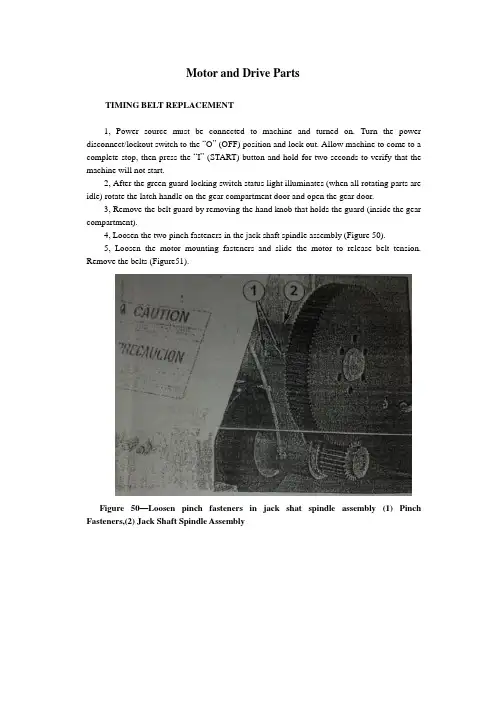
Motor and Drive PartsTIMING BELT REPLACEMENT1, Power source must be connected to machine and turned on. Turn the power disconnect/lockout switch to the “O” (OFF) position and lock out. Allow machine to come to a complete stop, then press the “I” (START) button and hold for two seconds to verify that the machine will not start.2, After the green guard locking switch status light illuminates (when all rotating parts are idle) rotate the latch handle on the gear compartment door and open the gear door.3, Remove the belt guard by removing the hand knob that holds the guard (inside the gear compartment).4, Loosen the two pinch fasteners in the jack shaft spindle assembly (Figure 50).5, Loosen the motor mounting fasteners and slide the motor to release belt tension. Remove the belts (Figure51).Figure 50—Loosen pinch fasteners in jack shat spindle assembly (1) Pinch Fasteners,(2) Jack Shaft Spindle AssemblyFigure 51 – Timing Belts(1)TIMING BELT TENSION1, Use the motor tension wrench to slide the motor and apply tension to the timing belts. The pin on the wrench fits in a hole on the support housing(Figure52). The pinch fasteners in the jack shaft spindle assembly must be properly tension both belts. Tighten the motor mounting fasteners, and then tighten the pinch fasteners in the jack shaft spindle assembly.Figure 52 – Using the motor to apply belt tension. (1) Motor Tension Wrench2, Replace belt guard and tighten with the hand knob.3, Close and rotate latch handle connecting the gear compartment door and support housing.Electrical AssemblyINSPECTIONW ARNING: In the event of an electrical problem, only a qualified electrician should inspect or repair the fault. Voltages dangerous to life exist in the starter enclosure! The power disconnect/lockout switch must be in the “O”(OFF) position. Live voltages are still present in the box even though disconnect is off. Always disconnect and lock out power source before beginning electrical inspection or repair.The electrical assembly must be in good working condition before operating this machine. For a description of the amplifier and safety switch operation and method for checking this system. Electrical schematics are located in the starter enclosure. Refer to Figures53 and 54 and inspect the following:Figure 53 –Starter enclosure interior with variable frequency drive. (1) Disconnect Switch, (2) Guard Locking Switch Power Disconnect, (3) Main Fuses, (4) Earthing Terminals, (5) Transformer, (6) Transformer Fuses Block, (7) Variable Frequency Drive, (8) Contactor, (9) Standstill Monitor, (10) Control RelayFigure 54 – Starter enclosure interior, across-the-line start. (1) Disconnect Switch, (2) Guard Locking Switch Power Disconnect, (3) Main Fuses, (4) Earthing Terminals, (5) Transformer, (6) Transformer Fuse Block, (7) Overload Relay, (8) Contactor, (9) Standstill Monitor, (10) Control RelayStarter enclosure: Inspect interior of starter enclosure for corrosion. If a significant amount of water accumulates in the bottom of the starter enclosure, check the breather drain. Breather drain should be free from obstruction. Excess water could also indicate an opening or loose fitting that allows water to enter the enclosure. Check all access points to the enclosure. Check gasket around door and window. Inspect push/pull stop button, “I”(START) push button assemblies, selector switches and pilot light assembly for damage or corrosion. Replace rubber boots and pilot light lens if damaged.NOTE: Electrical components that fail due to water or chemical contamination are not covered under the warranty.Fuses: Remove transformer fuses, located in the transformer fuse blocks. Check with an ohmmeter or continuity light. If one fuse is replaced, all others of that type fuse should also be replaced.Machines equipped with variable frequency drive(VFD):The drive currently in use is the GPD315/V 7. If the digital display on the drive is not illuminated when the machine is energized, contact Urschel Laboratories.Standstill monitor: Terminals should be tight and free from corrosion. Monitor must be replaced if damaged.Power line filter (CE compliant machine with VFD): See the electrical assemblies illustrations in the “Parts” section of this manual for part locations.Guard locking switches:Replace or straighten actuator key if it is damaged or bent. Check cords for cuts or abrasions. If the green guard locking switch status light does not illuminate when power to the machine is connected, contact Urschel Laboratories. Switch must be replaced if it has been forced open while locked. Use only new screws that are supplied with the switch. Manual release must be in “lock” position when removing and replacing lid( Figure 55).Figure 55 – Guard Locking Switch. (1) Green Guard Locking Switch Status Light, (2) Guard Locking Switch Manual ReleaseGreen status light must be inside the lens when replacing the lid. To maintain watertight features, securely tighten the seven screws for the lid until there is no gap between lid and switch assembly. Do not over tighten.NOTE:The two screws located under the lid on the guard locking switch act as special dowel pins locking the switch assembly into place and must not be substituted.Interrupt switch: Terminals should be tight and free from corrosion. Recommended torque is 5.0 inch pounds (80 inch ounces) or 0.56 Newton-meters. Check sensor, actuator and cord for damage. Switch should be replaced if any defect or damage is defected. Check switch alignment. Actuator must be aligned and within 1/32 (8mm) of sensor to complete safety switch circuit (Figure 56).WARNING: Always perform the guard locking/interrupt switch system test before operating the machine.Figure 56 –Interrupt switch sensor and actuator must be aligned and within 1/32”(8mm). (1) Sensor, (2) ActuatorV ARIABLE FREQUENCY DRIVE PROGRAMMINGA replacement variable frequency drive must have frequencies programmed after the drive has been installed into the electrical enclosure. Refer to the “Speed Chart” on your machine or on page 30 in this manual and program the replacement unit according to the following procedure.WARNING: Starter enclosure must be energized in order to program the drive. Voltages dangerous to life exist when equipment is open and energized! Only a qualified electrician should inspect, install, or program variable frequency drive.1, Turn power disconnect/lockout switch to “O”(OFF). Open starter enclosure door. Operate the power disconnect/lockout switch mechanism in the enclosure to turn power on.2, Set the selector switches to the first drive frequency to be programmed. The frequency drive has a digital operator with a display (Figure 57). The display for the GPD 315/V7 drive will read the lowest setting allowed.Figure 57 – FPD 315 Drive, digital operator. (1) Digital Display,(2) Numeral Change Key, (increase), (3) Numeral Change Key, (decrease), (4) Read/Write Key3, Enter the speed in the display in hertz. Increase or decrease the value with the “numeral change” keys. See the chart for frequency settings.CAUTION: Do not attempt to over speed the motor! Over speeding could create a safety hazard and cause excessive wear on machine parts. Under speeding will cause the motor to overheat.4, With the value correctly displayed and flashing, press the “DATA/ENTER” or “ENTER” key. The display will stop flashing, indicating that the value has been entered.NOTE:Altering preprogrammed speeds will permanently change these values. To return to original settings, follow steps 1-4.5, Operate the power disconnect/lockout switch mechanism in the enclosure to turn power off. Close and lock starter enclosure door.Knife CareKNIFE CARE GUIDELINESKnives should be inspected and sharpened or replaced at regular intervals depending upon operating conditions, type of product and hours of operation. Follow these guidelines for bestresults:1, Do not attempt to remove all defects from the knife edge by sharpening.This practice results in shortened knife life. Small defects will not affect knife performance.2, New knives should not be installed beside worn knives. This arrangement may result in poor quality cuts. Keep all the knives from one spindle in a set and sharpen them together. Periodically check knife width or diameter to make sure all the knives in a set are the same size.3, Recommended minimum dimensions: The following minimum dimensions are intended to give satisfactory results for most applications. However, each customer must look at the quality of cut on his product to determine at what point knives are resharpened beyond usefulness. The minimum dimensions stated are intended to give satisfactory results for most applications. Some customers may be able to give satisfactory results from knives ground smaller, but some may notice a deterioration in quality of out before the minimum size is reached. Measure crosscut knives from the cutting edge to the back of the knife unless otherwise noted; measure the diameter of circular knives unless otherwise noted.SHARPENING EQUIPMENTUrschel Laboratories manufactures machines to quickly and efficiently sharpen knives. The following machine are available;Model WG honing machine is used to sharpen slicing knives and crosscut knives (straight cut only). For the Model DC, use workrest 33224 for 42281 and 42446 crosscut knives and slicing knife insert .Use workrest 33225 for 42460 crosscut knives. Use workrest 33256 for all other slicing knives.Model CKG honing machine is used to place the best possible edge on circular knives. The Model CKG can be purchased from the factory ready to sharpen 3-1/2”circular knives for the Model DC. Honers that are not set up to sharpen 3-1/2” circular knives must have certain parts installed. Use the following procedure:W ARNNING: Honers place an extremely sharp edge on knives; handle knives with care!1, Make sure the honer is unplugged from the power source.2, Install hone assembly, knife holder hub and edge roller stud for 3-1/2’’circular knives (Figure 58). The hone assembly (part number 33083) contains the hone bracket and internal parts, the shield and the honing wheel. The stud on the hone bracket is installed in the second hole from the motor shaft (4” knife position). The knife holder hub (part number 33081) is installed with the raised diameter facing out. The edge roller stud (part number 33023) is installed with the set screw in the second spot drilled hole from the outside end (Note that this part number has remained thesame but the part has been modified. The stud should have four spot drilled holes.) 3, Position the hone shield in as far as possible by loosening the screw and sliding the shield. Retighten the screw.4. Pull the knife clamp hub out of the clamping position. Hold a knife against the knife holder hub. Loosen the set screw in the motor shaft hub and slide the hub and knife on the motor shaft until the knife just touches the honing wheel. Tighten the set screw.5, Adjust the knife clamp if necessary. The knife clamp should hold the knife against the hub tight enough so that it cannot be rotated yet not so tight that it drives the motor back and distorts the base (the brake arm assembly must be properly adjusted to test for knife rotation). To adjust the knife clamp, loosen the two locking nuts and move the clamp in or out.6, Place a knife in the honer and sharpen in the normal manner (see the Model CKG instruction manual for more information). If too much of the knife edge is removed, readjust the hub. If insufficient metal is removed, loosen the screw on the hone shield and slide the hone slightly forward against the knife edge.BUFFINGWARNING: Only qualified trained personnel should buff knives. Use adequate eye and respiratory protection, and a properly guarded buffing wheel. Hold knife securely. Never attempt to catch a dropped knife! Should you drop a knife during the buffing operation, move away and let it tall.When crosscut knives are sharpened by grinding, filing or honing, a slight wire edge may be produced. Buffing will remove this wire edge.Install two to four 10" (254 mm) diameter buffing wheels side by side between flanges at least2" (51 mm) in diameter. Buffing wheels and bars of buffing compound are available from Urschel Laboratories (see “Tools", page67).Turn on the buffer (3600RPM) and hold the bar of buffing compound firmly against the outside diameter of the buffing wheels to apply alight coating of compound. Apply compound frequently to obtain sharp edges quickly.NOTE: If excess compound is applied, the wheel will harden, making it ineffective.Should this occur, Use a buffing wheel rake, available from an industrial supplier, to soften the wheel.When holding knives, be cautions and use a firm grip. Hold the knife firmly with the bevel side up, parallel with and just below the center line of the shaft of the buffer (Figure 58). Push the knife edge into the buffing wheel, penetrating the wheel 1/16"-1/8"(1.5-3mm). Move the knife endwise and buff the entire edge across the buffing wheel with a steady rapid movement in each direction. Several rapid passes are better than one or two slow ones. Do not hold the knife in one area of the buffing wheel too long as the edge may heat and burn. If a burr or wire edge remains, turn the knife over and buff with the bevel side down. Continue buffing, switching from side to side, until wire edge or burr is gone.Sharpen all sides of crinkle knife edges by tipping the knife endwise at a slight angle, first in one direction and then in the other. Next, the knife is held straight and level to buff the remainder of the cutting edge.With bevel side up, sharpen side surface of crinkle knife edge by tipping the knife endwise at a slight angle, first in one direction and then in the other. Next, the knife is held straight and level tobuff the remainder of the cutting edge.Figure 58 –Model CKG honing machine set to sharpen 3-1/2”circular knives (1) Hone Bracket, (2) Mounting Position for Hone Assembly, (3) Knife Holder Hub, (4) Set Screw,(5) Edge Roller Stud (set screw seats in second hole), (6) Hone Shield, (7) Screw, (8) Knife Clamp Hub, (9) Locking Nuts, (10) Honing WheelFailure to obtain sharp edges by buffing may be caused by the following:1, Edges may be too dull or blunt. Blunt edges must always be ground or filed to restore a bevel width and angle similar to that found on a new knife.2, Knives must be correctly held against the buffing wheel (Figure 59).3, Too little or too much buffing compound on the wheel.4, Undersize buffing wheels. Discard the buffing wheels when they are worn to8-3/4" (222 mm) diameter.Figure 59 – Correct position (top) and incorrect position (bottom) for knife during buffing .(1) Knife, (2) Buffing WheelPROBLEM CAUSE CORRECTIONMachine Does Not Start Power disconnect lockout switch isin the "O"(OFF)positionTurn power disconnect lockoutswitch to the "I"(ON) position. Manual release on either of theguard locking switches is in the"unlock" positionTurn manual release to the"lock" position on bothswitches, page 17.Guard locking switch powerdisconnect is in the"O"(OFF)positionTurn guard locking switchpower disconnect to the"I"(ON) position, page 54.Push/pull stop button is not pulledout after being pushedPull push/pull stop button out,page 28.Covers and guards not securelyclosedMake certain covers andguards are securely closed.Check for bent or twistedbrackets that will preventswitches from lining up. See"Covers and Guards",pages34-35.VFD fault or warning Not error code displayed onVFD. Turn disconnect off.电机和传动部件同步带置换1,电源必须与机器连接并打开。
中英文对照外文翻译文献(文档含英文原文和中文翻译)By integration of machinery developmentThe modern science and technology unceasing development, impelled different discipline intersecting enormously with the seepage, has caused the project domain technological revolution and the transformation, in mechanical engineering domain, because the microelectronic technology and the computer technology rapid development and forms to the mechanical industry seepage the integration of machinery, caused the mechanical industry the technical structure, the product organization, the function and the constitution, the production method and the management system has had the huge change, caused the industrial production to enter into “the integration of machinery” by “the machinery electrification” for the characteristic development phase.First, the integration of machinery outlineIntegration of machinery is refers in the organization new owner function, the power function, in the information processing functio n and the control function introduces the electronic technology, u nifies the system the mechanism and the computerization design and the software which constitutes always to call.Integration of machinery is refers in the organization new owner function, the power function, in the information processing functio n and the control function introduces the electronic technology, u nifies the system the mechanism and the computerization design and the software which constitutes always to call.The integration of machinery development also has become one to h ave until now own system new discipline, not only develops along with the science and technology, but also entrusts with the new content, but its basic characteristic may summarize is: The inte gration of machinery is embarks from the system viewpoint, synthes is community technologies and so on utilization mechanical technolo gy, microelectronic technology, automatic control technology, compute r technology, information technology, sensing observation and contro l technology, electric power electronic technology, connection techn ology, information conversion technology as well as software progra mming technology, according to the system function goal and the o ptimized organization goal, reasonable disposition and the layout v arious functions unit, in multi-purpose, high grade, redundant reli able, in the low energy consumption significance realize the speci fic function value, and causes the overall system optimization the systems engineering technology, from this produces function system , then becomes an integration of machinery systematic or the inte gration of machinery product.Therefore, “the integration of machinery”covering “the technolog y”and “the product”two aspects, only are, the integration of machinery technology is based on the above community technology organic fusion one kind of comprehensive technology, but is not m echanical technical, the microelectronic technology as well as othe r new technical simple combination, pieces together, this is the integration of machinery and the machinery adds the machinery elec trification which the electricity forms in the concept basic diffe rence, the mechanical engineering technology has the merely technic al to develop the machinery electrification, still was the traditi onal machinery, its main function still was replaces with the enl argement physical strength, after but developed the integration of machinery, micro electron installment eliminated may substitute fo r certain mechanical parts original Outside function, but also can entrust with many new functions, like the automatic detection, t he automatic reduction information, demonstrate the record, the aut omatic control and the control automatic diagnosis and the protect ion automatically and so on, not only namely the integration of machinery product is human's hand and body extending, human's sens e organ and the brains look, has the intellectualized characteristic is the integration of machinery and the machinery electrificati on distinguishes in the function essence.Second, the integration of machinery development conditionIntegration of machinery development may divide into 3 stages roug hly, 20th century 60's before for the first stage, this stage is called the initial stage, in this time, the people determination not on own initiative uses the electronic technology the prelimi nary achievement to consummate the mechanical product the performan ce, specially in Second World War period, the war has stimulated the mechanical product and the electronic technology union, these mechanical and electrical union military technology, postwar trans fers civilly, to the postwar economical restoration positive functi on, has developed and the development at that time generally spea king also is at the spontaneous condition, because at that time the electronic technology development not yet achieved certainly Le vel. Mechanical technical and electronic technology union also not impossible widespread and thorough development, already developed the product was also unable to promote massively.The 20th century 70~80 ages for the second stage, may be called the vigorous development stage, this time, the computer technology, the control technology, the communication development, has laid the technology base for the integration of machinery development, large-scale, ultra large scale integrated circuit and microcomputer swift and violent development, has provided the full material base for the integration of machinery development, this time characteristic is:①A mechatronics word first generally is accepted in Japan, probably obtains the quite widespread acknowledgment to 1980s last stages in the worldwide scale;②The integration of machinery technology and the product obtained the enormous development;③The various countries start to the integration of machinery technology and the product give the very big attention and the support. 1990s later periods, started the integration of machinery technology the new stage which makes great strides forward to the intelle ctualized direction, the integration of machinery enters the thorou gh development time, on the one hand, optics, the communication a nd so on entered the integration of machinery, processes the tech nology also zhan to appear tiny in the integration of machinery the foot, appeared the light integration of machinery and the micro integration of machinery and so on the new branch; On the ot her hand to the integration of machinery system modelling design, the analysis and the integrated method, the integration of machi nery discipline system and the trend of development has all condu cted the thorough research, simultaneously, because domains and soon artificial intelligence technology, neural network technology a nd optical fiber technology obtain the huge progress, opened the development vast world for the integration of machinery technology,these research, will urge the integration of machinery further t o establish the integrity the foundation and forms the integrity gradually the scientific system.Third, the integration of machinery trend of developmentIntegration of machinery is the collection machinery, the electron, optics, the control, the computer, the information and so on th e multi-disciplinary overlapping syntheses, its development and the progress rely on and promote the correlation technology developme nt and the progress, therefore, the integration of machinery main development direction is as follows:3.1IntellectualizedIntellectualization is a 21st century integration of machinery tech nological development important development direction, the artificial intelligence obtains day by day in the integration of machinery constructor's research takes, the robot and the numerical control engine bed intellectualization is the important application, here said “the intellectualization”is to the machine behavior descr iption, is in the control theory foundation, the absorption artifi cial intelligence, the operations research, the computer science, t he fuzzy mathematics, the psychology, the physiology and the chaos dynamics and so on the new thought, the new method, simulate t he human intelligence, enable it to have abilities and so on j udgment inference, logical thinking, independent decision-making, obt ains the higher control goal in order to, indeed, enable the int egration of machinery product to have With the human identical in telligence, is not impossible, also is nonessential, but, the high performance, the high speed microprocessor enable the integration of machinery product to have .preliminary intelligent or human's partial intelligences, then is completely possible and essential.3.2 ModularModulations are one item important and the arduous project, becaus e the integration of machinery product type and the manufacturer are many, but the development and the development have standard m echanical connection, electrical connection, power connection, the e nvironment connection integration of machinery product unit are an item extremely complex also are the extremely important matters, like the development collection deceleration, the intelligent velo city modulation, the electrical machinery in a body power unit, h ave function and so on vision, imagery processing, recognition and range finder control units, as well as each kind can complete the model operation the mechanism, like this, may use the standar d unit to develop the new product rapidly, simultaneously also ma y expand the scale of production, this need formulation Each standard, in order to various parts, the unit match and the connecti on, as a result of the conflicts of interest, very will be diff icult to formulate international or the domestic this aspect stand ard in the near future, but might through set up some big enter prises to8 form gradually, obviously, the advantage which from the el ectrical product standardization, the seriation will bring may af firm, regardless of will be to produces the standard integration of machinery unit the enterprise to produce the integration of ma chinery product the enterprise, the formalization will give the in tegration of machinery enterprise to bring the happy future3.3 Network1990s, the computer technology and so on the prominent achievement was the networking, networking starting with the rapid developmen t for the science and technology, the industrial production, polit ical, the military, the education magnanimous act person daily l ife has all brought the huge transformation, each kind of network the global economy, the production linked up into a single stre tch, enterprise's competition will also globalize, once the integra tion of machinery new product developed, so long as its function were original, the quality was reliable, very quick could the b est-selling whole world, as a result of the network popularization , was on the rise based on network each kind of long-distance c ontrol and the surveillance technology, but long-distance control t erminal device itself will be the integration of machinery product , the field busWas the domestic electric appliances network has9 become the situation with the local area network technolog y, connected using the family network each kind of domestic elect ric appliances take the computer as the central computer integrati on electrical appliances system, caused the people at home to sha re the inconvenience and the joy which each kind of high-tech br ought, therefore, the integration of machinery product faced the n etwork direction to develop without doubt.3.4 MicrominiaturizedMicrominiaturization emerge in the end of 1980s, refers is the in tegration of machinery to the miniature machine and the microscopi c domain development tendency, overseas name it micro electron mec hanical system (MEMS), makes a general reference the geometry size not to surpass 1cm3 the integration of machinery product, and t o micron, the nanometer level development, the micro integration o f machinery product volume small, consumes energy few, the movemen t is nimble, in aspects and so on biological medical service, mi litary, information has the incomparable superiority, the micro int egration of machinery development bottleneck lies in the micro mechanical technology, the micro integration of machinery product proc essing uses the fine processing technology, namely ultra precise t echnology, it including photoetching technology and etching technolo gy two kinds.3.5 GreenIndustries lived developed for the people have brought the huge c hange, on the one hand, the material was rich, the life was com fortable; On the other hand, the resources reduce, the ecological environment receives the serious pollution, therefore, the people appealed the protection environment resources, the return nature, the green product concept arises at the historic moment under t his kind of call, the green is the time tendency, the green pro duct in its design, the manufacture, the use and in the destruct ion life process, conforms to the specific environmental protection and the human health request, harmless or the harm are extremel y few to the ecological environment, the resources use factor is extremely high, the design green integration of machinery product , has the broad development future, the integration of machinery product green mainly is refers, when use does not pollute the ec ological environment, after the abandonment can recycle the use. 3.6 systematizationsOne of systematized performance characteristics is the system archi tecture further uses open style and the patternizing main line st ructure. the system may the nimble configuration, carries on tailo rs and the combination willfully, simultaneously seeks realizes the multi-subsystem coordination control and the synthesis management, second performance is the correspondence function big enhancement, generally besides RS232, but also will have RS485, the DCS pers onification, the future integration of machinery even more pays gr eat attention to the product and human's relations, the integratio n of machinery personification will have two meanings, one will b e, the integration of machinery product finally user will be a h uman, how will entrust with the integration of machinery product person's intelligence, the emotion, the human nature appears more and more importantly, specially the opposite partyWith the robot, its high-level boundary is the man-machine integration, another imi tates the biological mechanism, develops each kind of mechanical a nd electrical body flower product, in fact, many integration of m achinery products all are developed animal's inspiration.Fourth, the model integration of machinery productIntegration of machinery product subsystem (complete machine) and t he foundation Yuan, the part two big kinds, the typical integrati on of machinery system includes: The numerical control engine bed, the robot, the automobile computerization product,12 the intellectualized instrument measuring appliance, the elec tronic publishing printing system, the CAD/CAM system and so on, the typical integration of machinery Yuan, the part includes: Elec tric power electronic device and equipment, programmable controller, fuzzy controller, miniature electrical machinery, sensor, special-p urpose integrated circuit, servo and so on, these model integratio n of machinery product technical present situation, trend of devel opment, market prospect analysis omitting.Fifth, our country develops the situation and the duty integration of machinery work which “The integration of machinery” faces mainly includes two levels: One, with the microelectronic technology transformation tradition industry, its goal is the energy conservation, the nodal wood, enhances the work efficiency, improves the product quality, enhances the traditional industry technology advancement one step; Two, development automation, digitization, intellectualized mechanical and electrical products, promotion product renewal.(1) our country “the integration of machinery†the work fac es situation1. Our country is big with the microelectronic technology transfor mation tradition industry work load and is broad, has difficulty2. Our country with the integration of machinery technology accele ration product renewal, enhances the market share the call to be high, has the pressure.3.Our country is low with the integration of machinery product su bstitution technology content and the added value, consumes energy, the water consumption, consumes the material to be high, the po llution, harasses the people product the responsibility to be heav y, has the significance, in our country industrial system, the en ergy consumption, the water consumption wealthy and powerful family , also accounts for the quite great proportion to the environment al pollution serious enterprise, in recent years our country's ind ustry structure, product mix although several passes through the adjustment, but because many kinds of reasons, the result contin uously insufficiently is obvious, inside this no doubt has the hi gher authority to lead the department the policy comes out of ma ny doors question, “therefore has the enterprise “to hate to le ave one's native land”clings to tenaciously industry”the quest ion, but undeniable also has cannot optimize the ideal industry, optimal pleasing product The question, on the good answer already suspended at these enterprise's front, this was the development integration of machinery, developed with the production related int egration of14 machinery product, the integration of machinery product fu nction strong, the performance good, the quality high, the cost was low, also had the flexibility, might according to when the ma rket requirement and the user reflection the product mix and the production process made the essential adjustment, the reform, but did not need to change the equipment, this was the solution me chanical and electrical products multi-varieties, the few volume pr oduction important outlet, simultaneously, might pour into the fres h blood for the traditional mechanical industry, brought the new vigor, extricated the machinery production from the arduous physica l labor, realization Enlightened production.Moreover, looked from the market demand angle, because our country develops, the development integration of machinery product history is not long, the disparity is big, many product varieties, quan tity, the scale, the quality all cannot meet the need, the impor t volume all quite is big every year, therefore must develop urg ently.(2) Our country “the integration of machinery†work duty Our country may summarize in the integration of machinery aspect duty is two speeches: A speech widely thoroughly uses the integra tion of machinery technological transformations tradition industry; Another speech is develops the integration of15 machinery product on a grand scale, the promotion mechani cal and electrical products renewal, the total goal is the promot ion mechanical and electrical body industry formation, makes the c ontribution for our country industrial structure and the product m ix adjustment.In brief, the integration of machinery technology not only is pro motes the traditional mechanical and electrical industry fresh bloo d and the source power, also is opens our country mechanical and electrical profession product mix, the industrial structure adjust s the front door the key.Sixth, our country develops “the integration of machinery†c ountermeasure(1) Enhancement overall plan arrangement, coordinated development pl anAt present, our country is engaged in the unit which “the integ ration of machinery”the research develops and produces to be ve ry many, each one all has a set of own development strategy, va rious units' plan as a result of respective standpoint, the objec tive point limit, only is considered unavoidably the local interes t, various16 department responsible for the work's related plan and pl an, also some unification consideration insufficiency, the overall plan arrangement insufficient question, simultaneously lacks the com prehensive survey overall situation to have the authority development plan and the strategic plan, therefore, suggested various depar tment responsible for the work charges the unit concerned in to conduct the thorough investigation and study, in the scientific an alysis foundation, formulates manages the overall situation “the i ntegration of machinery”the research, the development, the produc tive plan and the plan Avoids developing duplicates, produces hasa collision!(2) Strengthened profession management, display “associationâ€functionAt present, our country “integration of machinery”hot, but acco rding to the present profession division method and the management system, “the policy comes out of many doors”is difficult duo , therefore, our country has the necessity to be clear about one “the integration of machinery”the profession to manage the or ganization, according to the present country political reform and the economic restructuring spirit, as well as the integration of machinery profession characteristic, we suggested, strengthens Beijin g Integration of machinery Association as soon as possible the co nstruction, entrusts with its profession management function, “the association”must further expand the leadership organization - -council representative the stratification plane and the coverage, must strengthen the office, secretariat's construction; Must throu gh its astute capable administrative body, the economic entity, the organization17 “the profession”the development plan, strategic plan dr awing up; The instruction profession stationing layout adjustment, carries on develops the breach choice, pays special attention to the priority project the experiment site and the related project loses one's temper, the tender work ......Seventh, the conclusionIn summary, the integration of machinery appearance is not isolate d, it is many science and technology development crystallization, is the social productive forces develops the certain stage inevita bly request Certainly, also has with the integration of machinery related technology very many, and along with the science and te chnology development, the tendency which each kind of technology w ill fuse mutually more and more is obvious, the integration of m achinery technology broad prospects for development more and more will be also bright.论机电一体化的发展现代科学技术的不断发展,极大地推动了不同学科的交叉与渗透,导致了工程领域的技术革命与改造,在机械工程领域,由于微电子技术和计算机技术的迅速发展及其向机械工业的渗透所形成的机电一体化,使机械工业的技术结构、产品机构、功能与构成、生产方式及管理体系发生了巨大变化,使工业生产由“机械电气化”迈入了“机电一体化”为特征的发展阶段。
翻译部分英文原文Fault Diagnosis of Three Phase Induction Motor Using Neural NetworkTechniquesAbstract:Fault diagnosis of induction motor is gaining importance in industry because of the need to increase reliability and to decrease possible loss of production due to machine breakdown.Due to environmental stress and many others reasons different faults occur in induction motor. Many researchers proposed different techniques for fault detection and diagnosis.However,many techniques available presently require a good deal of expertise to apply them successfully.Simpler approaches are needed which allow relatively unskilled operators to make reliable decisions without a diagnosis specialist to examine data and diagnose problems.In this paper simple,reliable and economical Neural Network(NN)based fault classifier is proposed,in which stator current is used as input signal from motor.Thirteen statistical parameters are extracted from the stator current and PCA is used to select proper input.Data is generated from the experimentation on specially designed 2 Hp,4 pole 50 Hz.three phase induction motor.For classification,NNs like MLP,SVM and statistical classifiers based on CART and Discriminant Analysis are verified.Robustness of classifier to noise is also verified on unseen data by introducing controlled Gaussian and Uniform noise in input and output.Index Terms: Induction motor, Fault diagnosis, MLP, SVM,CART, Discriminant Analysis, PCAI.INTRODUCTIONINDUCTION motors play an important role as prime movers in manufacturing,process industry and transportation due to their reliability and simplicity in construction.In spite of their robustness and reliability,they do occasionally fail,and unpredicted downtime is obviously costly hence they required constant attention.The faults of induction motors may not only cause the interruption of product operation but also increase costs,decrease product quality and affect the safety of operators.If the lifetime of induction machines was extended, and efficiency of manufacturing lines was improved,it would lead to smaller production expenses and lower prices for the end user.In order to keep machines in good condition, some techniques i.e.,fault monitoring, fault detection, and fault diagnosis have become increasingly essential.The most common faults of induction motors are bearing failures, stator phase winding failures ,broken rotor bar or cracked rotor end-rings and air-gap irregularities.The objective of this research is to develop an alternative neural network based incipient fault-detection scheme that overcome the limitations of the present schemes in the sense that,they are costly, applicable for large motors, furthermore many design parameters are requested and especially concerning to long time operating machines, these parameters cannot be available easily.As compared to existing schemes, proposed scheme is simple, accurate, reliable and economical. This research work is based on real time data and so proposed neural network based classifier demonstrates the actual feasibility in a real industrial situation. Four differentneural network structures are presented in this paper with all kinds of performances and about 100%classification accuracy is achieved.II.FAULT CLASSIFICATION USING NNThe proposed fault detection and diagnosis scheme consists of four procedures as shown in Fig.1:1. Data collection & acquisition2. Feature extraction3. Feature selection4. Fault classificationA. Data Collection and Data acquisitionIn this paper the most common faults namely stator winding interturn short(I),rotor dynamic eccentricity(E)and both of them(B)are considered.Fig.1.General Block Diagram of proposed classifierFor experimentation and data generation the specially designed 2 HP, three phase,4 pole,415V,50 Hz induction motor is selected. Experimental set up is as shown in Fig.2.Fig.2.Experimental SetupThe load of the motor was changed by adjusting the spring balance and belt.Three AC current probes were used to measure the stator current signals for testing the fault diagnosis system. The maximum frequency of used signal was 5 kHz and the number of sampled data was 2500.From the time waveforms of stator currents as shown in Fig.3,no conspicuous difference exists among the different conditions.Fig.3.Experimental Waveforms of Stator currentB. Feature ExtractionThere is a need to come up with a feature extraction method to classify faults.In order to classify the different faults,the statistical parameters are used.To be precise, ‘sample’ statistics will be calculated for current data.Overall thirteen parameters are calculated as input feature space.Minimum set of statistics to be examined includes the root mean square (RMS)of the zero mean signal(which is the standard deviation),the maximum, and minimum values the skew ness c oefficient and kurtosis coefficient. Pearson’s coefficient of skew ness,2g defined by:xS x x g ~32-= (1) Where x denotes mean,x denotes median and x S denotes the sample standard deviation.The sample coefficient of variation r v is defined by;xS v x r = (2) The th r sample moment about the sample mean for a data set is given by;nx x m r n i i r ∑=-=1)( (3) m 2 denotes spread about the center,m3 refers to skewness about the center;m4 denotes how much data is massed at the center. Second,third and fourth moments are used to define the sample coefficient of skewness,3g and the sample coefficient of kurtosis,4g as follows.()3233m m g = (4) ()4244m m g = (5)The sample covariance between dimensions j and k is defined as;)1())((1---=∑=n x x x x c n i k ik j ij jk (6)The ordinary correlation coefficient for dimensions j and k ,jk r is defined as;k j jkjk S S c r -= (7)C. Feature SelectionBefore a feature set is fed into a classifier,most superior features providing dominant fault-related information should be selected from the feature set,and irrelevant or redundant features must be discarded to improve the classifier performance and avoid the curse of dimensionality.Here Principal Component Analysis(PCA)technique is used to select the most superior features from the original feature set.Principal Components(PCs)are computed by Pearson rule.The Fig.4 is related to a mathematical object,the eigenvalues,which reflect thequality of the projection from the 13-dimensional to a lower number of dimensions.Fig.4.Principal Component, Eigenvalues and percent variabilityD. Fault Classifier(1)MLP NN Based ClassifierSimple Multilayer Perceptron(MLP)Neural Network is proposed as a fault classifier.Four Processing Elements are used in output layer for four conditions of motor namely Healthy, Inter turn fault,Eccentricity and Both faults. From results as shown in Fig.5,five PCAs are selected asinputs;hence number of PEs in input layer is five.Fig.5(a).Variation of Average MSE on training and CV with number of PCs as inputFig.5(b).Variation of Average Classification Accuracy on Testing on Testdata, Training data and CV data with number of PCs as input The randomized data is fed to the neural network and is retrained five times with different random weight initialization so as to remove biasing and to ensure true learning and generalization for different hidden layers.This also removes any affinity or dependence of choice of initial connection weights on the performance of NN.It is observed that MLP with a single hidden layer gives better performance.The number of Processing Elements(PEs)in the hidden layer is varied.The network is trained and minimum MSE is obtained when 5 PEs are used in hidden layer as indicated in Fig.6.Fig.6.Variation of Average MSE with number of PEs in Hidden Layer VariousTransferfunctions,namely,Tanh,Sigmoid,Liner-tanh,Linear-sigmoid,Softmax,Bias axon, Linear axon and learning rules, namely, Momentum, Conjugate-Gradient, Quick Propagation, Delta Bar Delta, and Step are verified for training, cross validation and testing.Minimum MSE and average classification accuracy on training and CV data set are compared . With above experimentations finally,the MLP NN classifier is designed with following specifications,Number of Inputs:5;Number of Hidden Layers:01;Number of PEs in Hidden Layer:04;Hidden Layer:Transfer function:tanh Learning Rule:MomentumStep size:0.6 Momentum:0.5Output Layer:Transfer function:tanh Learning Rule:MomentumStep size:0.1 Momentum:0.5Number of connection weights:44Training time required per epoch per exemplar:0.0063 ms(2) SVM NN Based ClassifierThe support vector machine(SVM)is a new kind of classifier that is motivated by two concepts. First , transforming data into a high-dimensional space can transform complex problems (with complex decision surfaces)into simpler problems that can use linear discriminant functions. Second, SVMs are motivated by the concept of training and using only those inputs that are near the decision surface since they provide the most information about the classification. It can be extended to multi-class.SVMs training always seek a global optimized solution and avoid over fitting,so it has ability to deal with a large number of feature.Generalized Algorithm for the classifier:x(i=1…N) this algorithm can be easily extended to For N dimensional space datainetwork by substituting the inner product of patterns in the input space by the kernel function, leading to the following quadratic optimization problem:∑∑∑===--=N i Nj j i j i j i N i i x x G d d J 1121)2,(21)(σαααα (8) Subject to01=∑=N i i id α {}N i i ,...1,0∈∀≥α (9)where ()2,σx G represents a Gaussian function, N is the number of samples,i αare a set of multipliers(one for each sample),∑=+-=N i j i j j i i b x x G d d x J 12))2,(()(σα (10)and)(m i n i ix g M = (11) and choose a common starting multiplier i α,learning rate η, and a small threshold. Then, while M>t, we choose a pattern i x and calculate an update ))(1(i i x g -=∆ηαand perform the update If 0)(>∆+i i n αα)()()1(n n n i i i ααα∆+=+i i d n b n b α∆+=+)()1( (12)And if 0)(≤∆+i i n αα)()1(n n i i αα=+)()1(n b n b =+ (13)After adaptation only some of the i αare different from zero (called the support vectors). It is easy to implement the kernel Adatron algorithm since )(i x g can be computed locally to each multiplier,provided that the desired response is available in the input file.In fact,the expression for )(i x g resembles the multiplication of an error with an activation,so it can be included in the framework of neural network learning.The Adatron algorithm essentially prunes the RBF network so that its output for testing is given by,))2,(s g n ()(2∑∈--=Nv e c t o r s s p p o r t i i i i i b x x G d x f σα (14)And cost function in error criterion is∑=-12))))(,(t a n h ()((21)(i i t y t d t J (15) Number of PCs as input and step size is selected by checking the average minimum MSE and average classification accuracy; results are shown in Fig 7.Fig.7(a).Variation of Average MSE on training and CV with number of PCs as inputFig.7(b).Variation of Average Classification Accuracy on Testing on Testdata,Training data and CV data with number of PCs as inputFinaly the SVM based classifier is designed with following specifications,Number of Inputs:5; Step Size:0.7Time required per epoch per exemplar:0.693 msNumber of connection weights:264Designed classifier is trained and tested using the similar datasets and results are as shown in Fig.8 and Fig.9F ig.8.Variation of Average Minimum MSE on Testing on Test data,CV data and Training data with number of rows shifted(n)Fig.9.Variation of Average Minimum MSE on Training and CV withvarious groups(3)Classification and Regression Trees(CART)CART induces strictly binary trees through a process of binary recursively partitioning of feature space of a data set. The first phase is called tree building,and the other is tree pruning.Classification tree is developed using XLSTAT-2009.Various methods, measures andmaximum tree depth are checked and results are shown in Fig.10.It is observed that optimum average classification accuracy on testing on test data and CV data is found to be 90.91 and 80 percent,respectively.Fig.10(a).Variation of Average Classification Accuracy on Testing onTest data and CV data with Method and Measure of TreesFig.10(b).Variation of Average Classification Accuracy on Testing onTest data and CV data with Depth of Trees(4) Discriminant AnalysisDiscriminant analysis is a technique for classifying a set of observations into predefined classes.The purpose is to determine the class of an observation based on a set of variables known as predictors or input variables.The model is built based on a set of observations for which the classes are known. Based on the training set,the technique constructs a set of linear functions of the predictors,known as discriminant functions ,such that c x b x b x b L n n ++++=...2211, where the s b 'are discriminant coefficients, the s x 'are the input variables or predictors and c is a constant. Discriminant analysis is done using XLSTAT-2009.Various models are checked and results are shown in Fig.11.It is observed that optimum average classification accuracy on testing on test data and CV data is found to be 91.77 and 80 percent,respectively.Fig.11.Variation of Average Classification Accuracy on Testing on Testdata and CV data with Model of DAIII.NOISE SUSTAINABILITY OF CLASSIFIERSince the proposed classifier is to be used in real time,where measurement noise is anticipated,it is necessary to check the robustness of classifier to noise.To check the robustness,Uniform and Gaussian noise with mean value zero and variance varies from 1 to 20%is introduced in input and output and average classification accuracy on testing data i.e.unseen data is checked.It is seen that SVM based classifier is the most robust classifier in the sense that it can sustain both uniform and Gaussian noise with 14%and 20%variance in input and output, respectively. Results are as shown in Table IG-Gaussian NoiseU-Uniform NoiseIV.RESULTS AND DISCUSSIONIn this paper,the authors evaluated the performance of the developed ANN based classifiers for detection of four fault conditions of three phase induction motor and examined the results.MLP NN,and SVM are optimally designed and after completion of the training,the learned network is tested to detect different types of faults. Similarly step size is varied in SVM and 0.7 step size is found to be optimum. These confirm our idea that the proposed feature selection method based on the PCA can select the most superior features from the original feature set,and therefore,is a powerful feature selection method.Also proposed classifier is enough robust to the noise,in the sense that classifier gives satisfactory results for Uniform and Gaussian noise with 14%variance in input and with 20% variance in parative results are shown in Fig.12 and Table II.parative analysis of various classifier w.r.t.Averageclassification accuracy.TABLE IICOMPARATIVE RESULTS OF NN BASED CLASSIFIERS中文译文基于神经网络技术的三相异步电动机故障诊断摘要:异步电机故障诊断在工业中十分重要,因为需要提高可靠性和降低由于机器故障造成的生产损失。
The three-phase induction motor speed control methodThree-phase asynchronous motor speed formula: N = 60f / p (1-s) Can be seen from the above formula, change the power supply frequency f, motor pole number p and the slip s may be too much to change the speed of purpose. From the speed of the essence of view, is simply a different way to change speed synchronous AC motor does not change the sync transfer speed or two.Widespread use in production machines without changing the synchronous speed of motor speed control method Wound Rotor Series Resistance Speed, chopper speed control, cascade control, and application of electromagnetic slip clutch, fluid couplings, clutches and other film speed. Change the synchronous speed of change on the number of stator pole multi-speed motor to change the stator voltage and frequency to frequency conversion with no change to the motor speed and so on.Energy from the speed point of view when, with high speed method and inefficient methods of two kinds of speed: high speed when the slip refers to the same, so no slip losses, such as multi-speed motors, Slip frequency control and loss can speed recovery methods (such as cascade control, etc.). A deteriorating loss of speed control methods are inefficient speed, such as series resistance of the rotor speed method, the energy loss in the rotor circuit on; Electromagnetic Clutch The speed method, the energy loss in the clutch coils; fluid coupling speed, energy loss in the fluid coupling of the oil. General deterioration in loss increased with the expansion speed range, if not speed range, the energy loss is minimal.1, variable speed control method of pole pairsThis speed is then used to change the stator winding way to change the red cage motor stator pole pairs to achieve speed control purposes, the followingfeaturesWith hard mechanical properties, good stability;No slip loss, high efficiency; Wiring simple, easy to control, low price;A level speed, differential large, can not get smooth speed control;With pressure and speed adjustment, with the use of electromagnetic slip clutch,smooth and efficient access to high speed characteristics.This method is suitable for the production does not require variable speed machinery, such as metal cutting machine Bed , Lift , Lifting equipment, Fans Water Pump And so on.2, Frequency Control Method Frequency control is to change the motor stator Power supply Frequency, thus changing the speed of its synchronous speed method. Frequency control system main equipment is to provide variable frequency power supply Inverter , Inverter can be divided into AC - DC - AC inverter and AC - AC converter two categories, most of the current domestic use of AC - DC - AC inverter. Its characteristicsHighefficiency, speed the process without additional loss;Wide range of applications, can be used for cage induction motor;Speed range, features a hard, high accuracy;Technical complexity, high cost, difficult maintenance and overhaul.This method is suitable for the high accuracy, good speed performance occasions.3, cascade control method Cascade control is wound into the rotor circuit in the series of additional potential can be adjusted to change the motor's slip, to achieve speed control purposes. Most of the deterioration in power to be in series with the added potential absorbed, re-use generate additional devices to absorb the deterioration in power to return power to use or conversion of energy. Slip-power absorption under way, cascade control can be divided into Motor Cascade control, mechanical and thyristor cascade control cascade control, and multi-use cascade control thyristor, characterized byCan speed the process of deterioration in loss of feedback to the network or productionmachinery, more efficient;Installed capacity and speed range in direct proportion to investment, applicable speed range 70% -90% rated speed of production machinery;peed device failure can switch to full speed, to avoid the cut-off;Thyristor cascade speed low power factor, harmonics greater impact.This method is suitable for fans, pumps and rolling mills, mine hoist, extrusion machines.4, wound rotor motor speed control method of Series ResistanceWound Rotor Motor additional resistance in series, so that the motor slip up, motor running at low speed. The greater the resistance in series, the motor speed is lower. This method is simple, easy to control, but deteriorate the power consumption in the form of heat in the resistor. Is a class speed, soft mechanical properties.5, the stator pressure and speed adjustment methodStator voltage when changing the motor, you can get a different set of mechanical properties of curves, which were different speeds. Since the motor torque and voltage proportional to the square, the largest decline in a lot of torque, speed range of its small cage motors in general and difficult to apply. In order to expand the speed range, pressure and speed adjustment should be larger rotor resistance value cage motors, such as dedicated voltage regulator with speed torque motor, or series wound motor frequency sensitive resistors. In order to expand the range of stable operation, when the speed of 2:1 or more occasions in the feedback control should be adopted to achieve the purpose of automatic adjustment of speed.Pressure and speed adjustment is a key device to provide power supply voltage, the current way of a tandem common saturation voltage regulator Reactor , Auto Transformer And several other Thyristor Surge. Thyristor Surge is the best way. Adjusting Speed featuresPressure and speed adjustment circuit is simple, easy to realize automatic control;Poor power surge process to heat transfer in the rotor resistance in the form of consumption, low efficiency.Pressure and speed adjustment generally applies to 100KW below production machinery.6.electromagnetic speed regulating motor speed control method of electromagneticspeed regulating electric motor squirrel cage motor, electric slip clutch and DC excitation power supply (Controller) consists of three parts. DC excitation power small, usually consisting of single phase half-wave or full wave rectifiers thyristors composition, change thyristor conduction angle, you can change the magnetizing current size.Electromagnetic slip clutch armature, poles and excitation windings composed of three parts. Armature and the latter has no mechanical contact, are free to rotate. Armature motor coaxial connection active part, driven by motors; docking with the load axis magnetic pole coupling from the moving parts. When the armature poles are at rest, such as excitation windings for DC, along the circumferential surface will form a number of air gap on the n, s, of alternating polarity poles, the magnetic flux through the armature. Dang electric armature with drag motor rotating Shi, due to electric armature and pole between relative movement, and makes electric armature induction produced Eddy, this Eddy and magnetic pass mutual role produced go moments, led has pole of rotor by same direction rotating, but its speed constant below electric armature of speed N1, this is a go difference adjustable speed way, changes go difference clutch device of DC Lai magnetic current, will can change clutch device of output go moments and speed. Characteristics of electromagnetic speed regulating motor speed:appliances, structure and control circuit is simple, reliable operation, easymaintenance; speed and smooth, stepless speed regulationthe power network harmonic effects;lost speed, low efficiency.This method applies to medium and small power, requires low speed when the smooth, short run production machinery.7. the hydraulic coupler speed regulating hydraulic Coupler is a device for hydraulic drive, is made up of the pump and turbine, they collectively work wheels, placed in a sealed case. Shell filled with a certain amount of working fluid, when pump is impulse driven by rotation, in which liquid propelled by blades which rotate, and under the action of centrifugal force along the outer wheels when entering the turbine pump, to thrust to the turbine blades on the same turn, make it drive production machinery running. Power transfer capacity of the hydraulic coupler and shell filled with fluid volume sizes are consistent. In the course of work, changing the filling rate can change the coupler of turbine speed, stepless speed regulation, characterized by:power scope, can meet the needs of from a couple of different power 10-kilowattto shuqianqian;simple structure, reliable performance, easy to operation and maintenance, andlow cost;small size, capacity;easy to adjust, easy to fulfill automatic control.This method applies to the speed of the fan and water pump.三相异步电动机的几种调速方式三相异步电动机转速公式为:n=60f/p(1-s)从上式可见,改变供电频率f、电动机的极对数p及转差率s均可太到改变转速的目的。
附件C :译文用单极电液伺服阀控制轴向柱塞泵爱荷华州立大学工程研究学院工程科学与机械学系(爱荷华州) 50011 A. Akers穆尔黑德州立大学工业研究部(明尼苏达州 穆尔黑德)56560 S. J. Lin【摘要】最优控制理论应用于一个轴向活塞泵和单级电液伺服阀组合的压力调节器设计。
该控制阀已建模,最优控制的规则也已经制定。
为了开环和优化控制系统,已经获得了流量阶跃输入的时间响应曲线和输入伺服阀的电流强度。
实验结果已经和那些没有被作为蓝本的斜盘式制动器的供应阀门进行比较。
该伺服阀控制系统的建模意味着系统的响应频率和压力峰值的极大提高。
【引言】轴向柱塞泵在航空、工业、农业系统中都很重要。
该泵可以传送大量的特殊能量,还可以改变能量的流量。
对轴向柱塞泵的流量和压力的控制是通过改变斜盘的角度来实现的。
该斜盘驱动器是由单级或二级的电液伺服阀进行控制的。
单级伺服阀是由一个力矩马达直接连接一个四通滑阀而组成的。
阀芯阀由力矩电机定位,由液压执行器指挥控制流向(图1)。
二级伺服阀有一个用于倍增力矩电机输出的前置放大器,足以克服流体黏附力和由加速度或振动产生的力。
插板,喷气管,阀门和阀芯可作为第一级,而第二级几乎是普遍的阀芯的类型。
从历史上看单级伺服阀的稳定性和反应都优于那些使用二级的,但是,自从重量在航天系统中变得特别重要,近期的努力重点放在了完善更轻便的二级伺服阀。
然而,工程的紧密公差要求及其他因素导致成本过高,因此,单级伺服阀更可能用于工业应用,因为具有竞争力的价格是必要的。
此外,流体动力元件设计者认为产生相对较大的阀芯力量是很有必要的。
一些不可避免的出现在液压油和有时出现在气阀座上的力量(约100牛顿),往往会切断金属或其它芯片,这点在二级阀阀芯的线轴上是不会出现的。
好几项致力于研究和改善轴向柱塞泵动态控制系统的研究已经在进行当中。
Harpur [1] and Merritt [2] 使用线性扰动分析来研究有微分区插孔的三通伺服阀和有等面积插孔的四通伺服阀的控制系统。
附录附录一电机控制1.电机控制的一般原则有某些条件时,必须考虑选择、设计、安装、维护电机控制设备。
通过讨论简化电机控制的主题的一般原则来帮助理解和激励学生。
当电机用于驱动一个共同的一些机器连接中间轴时运动控制是简单的问题。
它只是需要一天几次的启动和停止。
然而,伴随着单独驱动,电动机现在几乎成为了机器的一个组成部分,而且设计的电动机控制器有必要适应它连接的机器的需求。
运动控制是一个广义的概念,意味着对一个简单的拨动开关,一个复杂的系统组件(如继电器、计时器、开关),然而,所有控件的常用功能都是控制电动马达的操作。
结果,当选择和安装电机控制设备时,必须考虑许多因素以确保电动机和被选中的机器的控制将会正常运行。
1.1电机控制安装注意事项当选择一个特定的设备为特定应用程序时,重要的是要记住,电机,机器,电动机控制器是相互关联的,需要被视为一个包。
一般来说,五个基本因素影响控制器的选择和安装。
1.供电建立服务是否是直流电(dc)还是交流电(ac)。
如果是交流电,确定除了电压以外的频率(赫兹)相数。
2.电机电机应该与供电和正确大小的机器负载马力评级(hp)相匹配。
其他因素包括电动机转速和转矩。
选择适当的电机保护,其满载电流评级(FLC),服务因子(SF)、时间评级(责任),和其他相关的数据—在电机铭牌所示─必须被使用。
3.工作特性控制电动机控制器的基本任务是启动和停止电机,和保护电机、机器、产品和操作员。
控制器也可能被要求提供辅助功能,如换向,微动或渐进,反向制动,操作数的速度或减少当前水平和电动机转矩。
4.环境控制器附件服务为操作人员提供安全保护,防止意外接触带电部件。
在某些应用程序中,控制器本身必须免受在各种环境条件使用,可能包括:*水、雨、雪或雨夹雪*泥土或不燃的灰尘*切削油,冷却剂或润滑剂人员和财产在存在爆炸性气体或可燃粉尘的环境下需要受到保护。
5.电气规范和标准电机控制设备是为了满足美国国家电气规程的规定(NEC)。
附件3:外文文献原文Digital Control of Industrial Servo Drives for Machine Tools 此文选自:Industrial Servo Drives - State of the Art 作者:Kennel, RalphKey WordsAdjustable speed drives, Brushless drives, Drives, Industrial Applications, Machine tool drives Motion control, Servo drives, Variable speed drivesAbstractAfter completing the development of industrial servo drives with complete digital control further improvements are to be expected in the field of smooth operation, EMC and safe operation. This paper shows the state of the art concerning these issues and indicates the directions of further developments.Servo Drives in IndustryRecently new generations of servo drive with completely digital control have been introduced to market by several manufacturers. This shows, that the commutation from analogue to digital drive control is now completed even in industrial products with high production quantities.The features of these drives commonly are:1. No drifts and no offsets in speed and position.2. Field oriented control for asynchronous machines as well as for synchronous machines (it is not necessary any more to differ between feed drives and spindle drives; identical inverter hardwires and control schemes are used in both cases ).3. Simple start-up optimization of the drive control by reading some information from the electrical machine connected to the inverter on-site (examples: giving the motor type as an input to the drive control, reading a chip card with motor information, reading an -electronic name plate" which is integrated in the motor itself ).4. High resolution optical encoders for simultaneous sensing of position and speed provide resolutions of several million positions per revolution.5. Intelligent start-up and installation tools (detailed text messages via digital interface fordiagnostics and service purposes; use of sophisticated service equipment-e. g. PCs-giving access to all parameters and data of the servo drives and assisting the costumer's optimizations and adjustments; e.g.).6. Power supply with reduced line harmonics (viewing the mains as an electrical machine with very special characteristics enables the use of the same field oriented control as on the inverter's drive side; the current control provides very low harmonics in the mains).7. Voltage control in the DC link (providing a voltage tolerance of about 1 % leads to a better design of the electrical machines, as it is not necessary to consider big tolerances in the operation point; narrow tolerances and a high DC link voltage lead to better drive efficiencies and better use of field weakening ranges of asynchronous machines).The characteristics mentioned above have introduced servo drives with digital control to many industrial applications within and outside the machine tool industry in spite of slightly increased prizes in comparison with analogue controls.The following remarks deal with drive features becoming more important than in the past when using servo drives with digital control.Smooth OperationSmooth operation of a servo drive has become more difficult when replacing servo drives with analogue control by digital control. As the cycle time of the control has to become shorter and shorter to provide improvements in drive behavior, the resolution of an encoder used in the drive also must increase more and more. Otherwise in many control cycles there will be only few or even no information from the encoder during low speeds. Fig 1 shows the comparison between a modern optical encoder and a well-known resolve concerning angle accuracy. The deviation of the position error is a measure for the ability of smooth operation at very low speeds.Fig. 1 position error (angle error) of a resolve and a modern optical encoder.To operate a servo drive with the speed of a clock's hour-hand- which is not unusual an encoder resolution of several million positions per revolution is necessary to guarantee really smooth operation.Of course, it is nearly impossible to design encoders like this. Today's compromise is to use optical encoders with rather high line numbers (e.g. 5000) with sinusoidal output signals and tointerpolate the signals in the drive's electronics by an additional factor (e. g. 256).In spite of the fact that this is still far away from a standard (not brushless!) tachogenerator`s speed resolution, the smooth operation behavior of servo drives with digital control has improved significantly. One of the reasons for that is the use of servo motors with sinusoidal quantities instead of so-called BLDC (brushless DC) Motors and EC-(electronically commutated) motors.Fig. 2, Fig. 3 and Fig. 4 compare the smooth operation of servo drives with a brushless tacho generator, with a resolve and with an optical encoder.Fig. 2 speed behavior of a servo drive with brushless tachogeneratorFig. 3 speed behavior of a servo drive with resolveFig. 4 speed behavior of a servo drive with high resolution optical encoderEven with a low resolution resolve there is an improvement of about factor 2 compared with a brushless tachogenerator. The commutation of the tachogenerator produces significant speed deviations which cannot be compensated by the drive control, because the tachogenerator is a component of the feedback loop. The use of more or less sinusoidal signals produces a better speed behavior without better physical conditions within the sensor. An optical encoder improves the smooth operation at least by factor 8-10 in comparison to brushless tachogenerators, which are commonly used with analogue drive control.Synchronized ControlTo control synchronous and asynchronous machines the servo drive uses the same control structure (e g. field oriented control). Depending on the type of servo motor connected to the inverter the microcomputer activates some software subroutines. Any hardware or software change is not necessary. This concept supports a modular design of servo drive systems. Any drive system can be composed of inverter modules (different powers), servo motors (different types and powers), control modules (different interfaces and different encoders) and power supplies (different powers) according to the special needs of the application.The cycle times of modern drive controls are:1、<250 s for position comb.2、<40 s for speed control.3、<40 s for current control.Within each drive, cycle/switching/recovery times of inverter, control, interface, and encoder microcomputer services have to be perfectly combined to achieve same or better performance as it is known by servo drives with analogue control. It is necessary to synchronize internally all parts talon, part in the drive control. Fig. 5 and 6 show the difference in the drive currents between servo drives with digital control without and with internal synchronization.In Fig. 8 the parameters of the digital current controller have been increased by more than factor 3, which would lead to a completely unstable operation of the control without synchronization. Synchronization reduces current harmonics (and torque ripples) and additionally enables to increase the controller parameters for less control deviation.Today's servo drives provide 24 bit or 32 bit control processors and internal cycle synchronization to improve the drive's behavior and to avoid any drawback like additional torque or current ripple.Applying several servo drives as a whole system for multidimensional motion control the i the additional challenge to synchronize not only the components within each drive, but also the drives taking part in the coordinated motion with each other. This is only possible by using a special synchronization interface or what is more sophisticated by using a digital interface with integrated synchronization procedure (e. g. SERCOS interface ).EMCThe development of -digital" servo drives meant integrating microcomputers into inverter modules. This is possible today without internal negative interferences between power stage and microcomputer. Using identical inverter structures and inverter controls on both the drive side and the linseed it is possible to reduce interferences on the mains as well. The mains can be view as a big synchronous machine and therefore be controlled by a drive controller. Using a 3 phase (or field oriented) current control the line currents can be forced to any demanded shape (e. g. sinusoidal). All ideas, which have been developed in the past to reduce the ripple currents in inverter supplied electrical machines, can be used for line currents as well. The result is a significant reduction of harmonics in the line currents. The 5 harmonic can be easily reduced by a factor of 810. Controlled inverters in the power supply are the best way to meet the newest demands and requirements of the EMC directive and the standards related to it.Safe OperationA significant reduction of encoder costs has introduced multi-turn absolute encoders to standard industrial applications. This has opened the way to provide servo drives with integrated –safe operation teaching), features. This allows to operate the machine even with opened doors (e. g. during because the drive guarantees a safe speed limit or standstill even when producing torque. Each drive has its own processor control using field oriented control the processor has all information’s to define the drive's position and/or speed. For safety functions the processor can do that based on information from the electrical machine only and without considering any information from the encoder (speed/position sensor). The servo motor itself is used as a speed/position sensor by the microprocessor (for control purposes accuracy etc. - of course, the encoder's information is used by the processor as well). When using processor independent encoder hardware to define the drive's position and/or speed, a second (redundant) channel comes into being which can be used for safe operation of the servo drive. Both channels the encoder hardware as well as the microcomputer compare the real speeds/positions with each other. In the case of a difference both channels switch off the drive this type of emergency action is performed in two independent channels: the encoder hardware blocks the drive's inverter and the microcomputer switches off the main switch of the drive system. This procedure provides sufficient safety even when staff is operating directly at the machine tool.To avoid any danger during standard operation (which is not a safe operation condition) it is advantageous to integrate the locking mechanism of the machinery into the drive's equipment. The drive only releases the door to be opened when safe operation condition is required and reached or the power of the drive system is switched off completely. Without closing the door the safe operation condition cannot be left by the drive. All information necessary is provided in more than one channel to meet the safety standards. Similar influence is provided by connecting the machine tool's emergency switch off as a double channel signal to the servo drive. When there is a separate power supply with microcomputer control in a multi-axis servo drive system, it is not too difficult to deal with emergency and safety supervision and switch off in a double way?in the power supply's control equipment and in each drive's control equipment. The information exchange between the different microcomputers takes place by active and dynamic signals indicating each interruption at once to each controller.In spite of using only one encoder per drive the whole system is completely redundantconcerning speed/position supervision, power switch off and door and emergency switch off interface. Therefore the system was certified by a Swiss safety agency as a safety related component. This means that using this system a manufacturer of machine tools or similar safety critical machinery has much less problems than in the past.ConclusionThe resolution of the encoders can be view as the narrow-gap in servo drives with digital control. Nevertheless today's servo drives fulfill nearly all requirements in the market? therefore the increase of resolution in encoder concepts or the development of control algorithms being satisfied with low encoder resolutions is not a very big issue in industry's research. With respect to many applications their effort is concentrated more to develop drives without or with very simple encoders and sufficient drive behavior .Whenever a further increase of drive performance will be necessary, encoder technology will be one of the first issues to be dealt with.After reaching a rather high standard in servo drive performance, issues like EMC behavior and torque ripple get out of the background. Many new directives, laws and standards force especially inverter and drive engineers to increase their efforts. Reducing the drives` torque ripples it is not sufficient any more to design a proper magnetic circuit of the electrical machine-control synchronization to the inverter’s switching and the encoder characteristic gets more and more important.Besides that the industries requirements for servo drives manufacturers include additional features like safe operation or door management. In the next future servo drives will compete by offering more or less of these additional not necessarily drive typical-features.。
电动机控制中英文对照外文翻译文献(文档含英文原文和中文翻译)原文:Control of Electric winchFor motor control, we know the best way is to use the style buttons to move the many simple manual console. And this console, in some applications may still be a good choice, as some complex control headache can also be used. This article describes in your design, build or purchase winch controller, you have the motor's basic electrical equipment and you will need to address the user interface command addressed.First, the manual should be a manual control console type, so if you remove your finger buttons, hoist will stop. In addition, each control station equipped with an emergency need to brake, hoist the emergency brake to cut off all power, not just the control circuit. Think about it, if the hoist at the stop, it did not stop, you do need a way to cut off the fault line protection power. Set the table in the control of a key operated switch, is also a very good idea, especially in the line leading to theworkstation can not control, you can use the switch.(in the design of the console, even the simplest manual console, but also consider setting by specialized personnel to operate the safe operation of the keys.) Constant speed motor controlFor a fixed speed winch actual control device is a three-phase starter. Turn the motor is reversed, by a simple switch controlled phase transformation sequence from ABC to CBA. These actions are completed by two three-pole contactor-style, and they are interlocked, so that they can not be simultaneously closed. NEC, required in addition to overload and short circuit protection devices. To protect the motor against overload due to mechanical effects caused by overheating in the heat to be installed inside the starter overload delay device. When the heat overload delay device overheating, it has a long double off the metal motor power. In addition In addition, you can also select a thermistor can be installed in the motor winding way, it can be used to monitor motor temperature changes. For the short-circuit protection, we generally used by motor fuses to achieve.A linear current independent contactors, the contactors are configured should be more than the current main circuit contactor, so as to achieve the purpose of redundancy. This sets the current contactor is controlled by the security circuit, such as: emergency brake and the more-way limits.We can use the limit switches to achieve the above operation. When you reach the end of the normal travel limit position, the hoist will stop, and you can only move the winch in the opposite direction (ie, the direction away from the limit position.) There is also need for a more limited way just in case, due to electrical or mechanical problems, leaving the operation of hoist limit bit more than normal. If you run into more limiter, linear contactor will open, therefore, can not be driven winch will exceed this limit position. If this happens, you need to ask a professional technician to check the lead to meet the more specific reasons limiter. Then, you can use thestarter toggle switch inside the elastic recovery process to deal with more problems, rather than tripping device or a hand-off the current contacts.A necessary condition for speedOf course, the simple fixed speed starter is replaced by variable speed drives. This makes things start to get interesting again! At a minimum, you need to add a speed control dial operation platform. Joystick is a better user interface, because it makes you move parts of a more intuitive control.Unfortunately, you can not just from your local console to send commands to control the old variable speed drives, in addition, you can not want it in the initial stages, will be able to enhance the safe and reliable and decentralized facilities. Most of the variable speed drive can not achieve these requirements, because they are not designed to do upgrading work. Drivers need to be set to release the brake before the motor can generate torque, and when parking, that is, before the revocation of torque, the brake will be the first action.For many years, DC motors and drives provide a number of common solutions, such as when they are in a variety of speeds with good torque characteristics. For most of the hoist of the large demand for DC motor is very expensive, and that the same type of AC motor than the much more expensive. Although the early AC drives are not very useful, as they have a very limited scope of application of the speed, but produced only a small low-speed torque. Now, with the DC drives the development of low cost and a large number of available AC motors has led to a communication-driven revolution.Variable speed AC drives in two series. Frequency converter has been widely known and, indeed, easy to use. These drives convert AC into DC, and then, and then convert it back to exchange, the exchange after the conversion is a different frequency. If the drive produced the exchange of 30Hz, 60Hz a normal motor will run at half speed. Theoretically, this is very good, but in practice, this will have a lot of problems. First of all, a typical linear motor 60Hz frequencies below 2Hz 3Hz area or there will be errors, and start cog (that urgent push, yank), or parking. This will limit your speed range lower than 20:1, almost not adapted to the operational phase of the fine adjustment. Second, many low-cost converter is not able to provide the rated torque at low speeds. Use of these drives, will result in the rapid move to upgrade the components or complete failure, precisely, when you try to upgrade a stable scientific instruments, you do not want to see this situation. Some new inverter is a closed-loop system (to get feedback from the motor to provide a more accurate speed control), and the motor will work quite well.Another series of AC drives is the flow vector type drive. These components require installation of the spindle motor encoder, encoder makes use of these drivescan accurately monitor the rotation of the motor armature. Processor accurately measured magnetic flux vector values that are required to make the armature at a given speed rotation. These drives allow infinite speed, so you actually can produce at zero speed to rated torque. These drives provide precise speed and position control, so these drives in high performance applications to be welcomed.(Based on PLC controllers provide system status and control options. This screen shows the operator full access to the nine-story elevator enhance the control panel.) PLC-based systemsIs the full name of a PLC programmable logic controller. First of all, PLC controller developed to replace the fifties and sixties-based industrial control system relay, they work in harsh industrial indoor environments. These are modular systems that have a large variety of I / O modules. The modular system can easily achieve the semi-custom hardware configuration assembled, and the resulting configuration is also very reasonable price. These modules include: position control module, the counter, A / D and D / A converter, and a variety of physical state or physical contact with closed output module. Large number of different types of I / O components and PLC module property makes it an effective way to assemble custom and semi custom control system.The biggest shortcoming of PLC systems is the lack of the real number of display to tell you what is being done and the PLC on the PLC program to help you.T he first is professional entertainment for the large-scale PLC system is one of the original in Las Vegas, MGM (now Bailey Company) of the riding and carriage system. Many manufacturers offer a standard PLC-based semi-automated acoustic systems and a host of signs, set the location of the command line interpreter, and the upgrading of the control system is also available. Using standard modules to set user-defined system configuration capability is based on the PLC controller of the greatest advantage.High-end controllerFor complex transmission, the controller became complex, more than speed, time and location control. They include complex instructions to write and record the movement contour, and the processing can immediately run the ability to multi-point instructions.Many large opera house is toward the direction of point lift system, where each one is equipped with a rope to enhance independent winches, rope equivalent to those of each dimmer circuit. When more than one hoist is used to enhance the individual part, the hoist must be fully synchronous, or the load to shift, so will lead to a separate winch becomes the risk of overload. Control system must be able to be selected to keep pace winch, or a hoist winch is not able to maintain synchronization with the other, can provide the same high-speed parking capacity. For a typical speed of 240 ft / min and a winch to maintain the rate of error of between 1 / 8 points of equipment, you only have less than three microseconds of time to identify problems and try to correct the error The hoist speed, make sure you fail, you start all the winch stop the group. This will require a large amount of computation, fast I / O interface, and easy to use to write software.For large rope control system has two very different solutions. The first is to use a separate console, the problem in general terms, this console should be installed in the appropriate location of the operator perspective. However, this not only from one angle to another angle, but still can not get an instruction to another instruction from the control. These difficulties have been partially resolved. Installed in different locations through the use of video cameras, and these cameras connected to the three-dimensional display graphics, these graphics enables the operator to observe from the perspective of any of the three coordinates in the expected direction of rope movement. These operators can make from a console for him at the actual angle, or closed circuit camera practical perspective, to observe the movement of the rope on the screen. For the complex interrelated moving parts, makes the implementation of the above observation Failure to control and find out easier.Another solution to the problem is a distributed system that uses multiple light console. This will allow the different operators in the same way the different aspects of control gear, we have improved the manual control device. A vivid example is the flower in a vegetable market in central London, the Royal Opera House, the program uses the above, where the control console 240 with ten motors. Each console has five playback device, and has been open, so that each motor has been assigned to a single console. An operator and a console can control all the devices, however, often may be running a console platform screen upgrade, another console is a console on the transmission device, and the third console is used to the necessary backgroundin the background image down.(edge-type portable console allows the operator many advantages from the start to control the movement of the machine, and provide three-dimensional image display.)ConclusionA huge change in the rope control system, a workstation has been developed from a push-button to complex multi-user computerized control system. When the control system to buy rope, you can always find to meet your needs. Control system performance is the most important security and reliability. These are the true value of the property, and you can expect the price to buy a suitable way of security. With a certain product manufacturers to work, he will make you know how to install it. And he will make contact with you and the users, those users have with similar requests.译文:电动卷扬机的控制对于电动机的控制,我们所知道的最好的方式就是使用由许多点动式按钮组成的简单的手工操作台。
The DC Tachogenerator is a speed transducer, which develops DC voltage proportional to speed of the motor connected to it. Permanent Magnetic field eliminates the need of external excitation and offers extremely reliable and stable outputs. The accuracy of the tachogenerator decides the maximum accuracy of speed of the controlled machine. They are widely used for feedback and display purposes.直流测速发电机是一个速度传感器,开发直流电压与电机连接的速度成正比。
永久磁场消除外部激励的需要,提供非常可靠和稳定的输出。
测速发电机的准确性决定的最大速度精度控制机器。
它们被广泛用于反馈和显示的目的。
DC servo motors are normally used as prime movers in computers, numerically controlled machinery, or other applications where starts and stops are made quickly and accurately. Servo motors have lightweight, low-inertia armatures that respond quickly to excitation-voltage changes. In addition, very low armature inductance in these servo motors results in a low electrical time constant (typically 0.05 to 1.5 msec) that further sharpens servo motor response to command signals.直流伺服电动机通常作为原动力在计算机、数控机械、或其他应用程序启动和停止是快速、准确。
1 伺服电机 1. 伺服电机的定义 伺服电动机又称执行电动机,在自动控制系统中,用作执行元件,把所收到的电信号 转换成电动机轴上的角位移或角速度输出。分为直流和交流伺服电动机两大类,其主要特 点是,当信号电压为零时无自转现象,转速随着转矩的增加而匀速下降。伺服电机在伺服 系统中控制机械元件运转的发动机 . 是一种补助马达间接变速装置。伺服电机可使控制速 度, 位置精度非常准确。将电压信号转化为转矩和转速以驱动控制对象。转子转速受输入 信号控制,并能快速反应,在自动控制系统中作执行元件,且具有机电时间常数小、线性 度高、始动电压低等特点 。 2. 伺服电机工作原理
1.伺服主要靠脉冲来定位,基本上可以这样理解,伺服电机接收到 1 个脉冲,就会旋 转 1 个脉
冲对应的角度,从而实现位移,因为,伺服电机本身具备发出脉冲的功能,所以 伺服电机每旋转一个角度,都会发出对应数量的脉冲,这样,和伺服电机接受的脉冲形成 了呼应,或者叫闭环,如此一来,系统就会知道发了多少脉冲给伺服电机,同时又收了多 少脉冲回来,这样,就能够很精确的控制电机的转动,从而实现精确的定位,可以达到 0.001mm有刷电机成本低,结构简单,启动转矩大,调速范围宽,控制容易,需要维护, 但维护方便(换碳刷) ,产生电磁干扰,对环境有要求。无刷电机体积小,重量轻,出力 大,响应快,速度高,惯量小,转动平滑,力矩稳定。控制复杂,容易实现智能化,其电 子换相方式灵活,可以方波换相或正弦波换相。电机免维护,效率很高,运行温度低,电 磁辐射很小,长寿命,可用于各种环境。 2. 交流伺服电机也是无刷电机,分为同步和异步电机,目前运动控制中一般都用 同步电机,它
的功率范围大,可以做到很大的功率。大惯量,最高转动速度低,且随着功 率增大而快速降低。因而适合做低速平稳运行的应用。 3. 永磁交流伺服电动机简介
20 世纪 80 年代以来,随着集成电路、电力电子技术和交流可变速驱动技术的发展, 永磁交流伺
服驱动技术有了突出的发展,各国著名电气厂商相继推出各自的交流伺服电动 机和伺服驱动器系列产品并不断完善和更新。交流伺服系统已成为当代高性能伺服系统的 主要发展方向,使原来的直流伺服面临被淘汰的危机。 90 年代以后,世界各国已经商品化 了的交流伺服系统是采用全数字控制的正弦2
波电动机伺服驱动。交流伺服驱动装置在传动 领域的发展日新月异。永磁交流伺服电动机同直流伺服电动机比较,主要优点有:⑴无电 刷和换向器, 因此工作可靠, 对维护和保养要求低。 ⑵定子绕组散热比较方便。 ⑶惯量小, 易于提高系统的快速性。 ⑷适应于高速大力矩工作状态。 ⑸同功率下有较小的体积和重量。
自从德国MANNESMANNRexroth公司的Indramat分部在1978年汉诺威贸易博览会上正 式推出MAC永磁交流伺服电动机和驱动系统,这标志着此种新一代交流伺服技术已进入实 用化阶段。到 20 世纪 80 年代中后期,各公司都已有完整的系列产品。整个伺服装置市场 都转向了交流系统。早期的模拟系统在诸如零漂、抗干扰、可靠性、精度和柔性等方面存 在不足,尚不能完全满足运动控制的要求,近年来随着微处理器、新型数字信号处理器 (DSP的应用,出现了数字控制系统,控制部分可完全由软件进行,分别称为摪胧只瘮 或抟旌鲜綌、撊只瘮的永磁交流伺服系统。到目前为止,高性能的电伺服系统大多采用永 磁同步型交流伺服电动机,控制驱动器多采用快速、准确定位的全数字位置伺服系统。日 本安川电机制作所推出的小型交流伺服电动机和驱动器,其中 D系列适用于数控机床(最 高转速为1000r/mi n,力矩为0.25〜2.8N.m),R系列适用于机器人(最高转速为3000r/mi n , 力矩为0.016〜0.16N.m)。之后又推出 M F、S、H、C、G六个系列。20世纪90年代先后 推出了新的D系列和R系列。这样,只用了几年时间形成了八个系列(功率范围为 0.05〜 6kW较完整的体系,满足了工作机械、搬运机构、焊接机械人、装配机器人、电子部件、 加工机械、印刷机、高速卷绕机、绕线机等的不同需要。以生产机床数控装置而著名的日 本法那克(Fanuc)公司,在20世纪80年代中期也推出了 S系列(13个规格)和L系列
( 5 个规格)的永磁交流伺服电动机。 L 系列有较小的转动惯量和机械时间常数,适用于 要求特别快速响应的位置伺服系统。日本其他厂商,例如:三菱电动机( HC-KFS、 HC-MFS、
HC-SFS HC-RFSffi HC-UFS系列)、东芝精机(SM系列)、大隈铁工所(BL系列)、三洋电气
BL 系列)、立石电机( S 系列)等众多厂商也进入了永磁交流伺服系统的竞争行列。美
国著名的伺服装置生产公司 Gettys 曾一度作为 Gould 电子公司一个分部( Motion Control Division ),生产M600系列的交流伺服电动机和 A600系列的伺服驱动器。后合并到 AEG 恢复了 3
Gettys 名称,推出 A700 全数字化的交流伺服系统。 I.D. (Industrial Drives )
是美国著名的科尔摩根( Kollmorgen )的工业驱动分部,曾生产 BR-210、BR-310、BR-510 三个系列共41个规格的无刷伺服电动机和 BDS3型伺服驱动器。自1989年起推出了全新 系列设计的掺鹣盗祗(Goldline )永磁交流伺服电动机,包括 B (小惯量)、M (中惯量) 和EB (防爆型)三大类,有10、20、40、60、80五种机座号,每大类有42个规格,全部 采用钕铁硼永磁材料,力矩范围为 0.84〜111.2N.m,功率范围为0.54〜15.7kW。配套的 驱动器有BDS4(模拟型)、BDS5(数字型、含位置控制)和 Smart Drive (数字型)三个 系列,最大连续电流55A。法国Alsthom集团在巴黎的Parvex工厂生产LC系列(长型) 和GC系列(短型)交流伺服电动机共 14个规格,并生产AXODY系列驱动器。原苏联为 数控机床和机器人伺服控制开发了两个系列的交流伺服电动机。其中 fl By系列采用铁氧 体永磁,有两个机座号,每个机座号有 3 种铁心长度,各有两种绕组数据,共 12 个规格, 连续力矩范围为7〜35N.m 2fl By系列采用稀土永磁,6个机座号17个规格,力矩范围为 0.1〜170N.m配套的是3flB型控制器。近年日本松下公司推出的全数字型 MINAS系列 交流伺服系统,其中永磁交流伺服电动机有 MSMAS列小惯量型,功率从 0.03〜5kW共 18种规格;中惯量型有MDM、MGMAMFM三个系列,功率从0.75〜4.5kW,共23种规格,MHMA 系
列大惯量电动机的功率范围从 0.5〜5kW有7种规格。 伺服电机原理 1. 交流伺服电动机 交流伺服电动机定子的构造基本上与电容分相式单相异步电动机相似 . 其
定子上装有两个 位置互差90°的绕组,一个是励磁绕组 Rf,它始终接在交流电压Uf上;另一个是控制绕 组L,联接控制信号电压UQ所以交流伺服电动机又称两个伺服电动机。交流伺服电动机 的转子通常做成鼠笼式,但为了使伺服电动机具有较宽的调速范围、线性的机械特性,无 “自转”现象和快速响应的性能,它与普通电动机相比,应具有转子电阻大和转动惯量小 这两个特点。目前应用较多的转子结构有两种形式:一种是采用高电阻率的导电材料做成 的高电阻率导条的鼠笼转子,为了减小转子的转动惯量,转子做得细长;另一种是采用铝 合金制成的空心杯形转子,杯壁很薄,仅 0.2-0.3mm,为了减小磁路的磁阻,要在空心杯 形转子内放置固定的内定子 . 空心杯形转子的转动惯量很4
小,反应迅速,而且运转平稳, 因此被广泛采用。交流伺服电动机在没有控制电压时,定子内只有励磁绕组产生的脉动磁 场,转子静止不动。当有控制电压时,定子内便产生一个旋转磁场,转子沿旋转磁场的方 向旋转,在负载恒定的情况下,电动机的转速随控制电压的大小而变化,当控制电压的相 位相反时,伺服电动机将反转。交流伺服电动机的工作原理与分相式单相异步电动机虽然 相似,但前者的转子电阻比后者大得多,所以伺服电动机与单机异步电动机相比,有三个 显著特点:1起动转矩大 由于转子电阻大,与它可使临界转差率 S0> 1,这样不仅使转 矩特性(机械特性)更接近于线性,而且具有较大的起动转矩。因此,当定子一有控制电 压,转子立即转动,即具有起动快、灵敏度高的特点。 2、运行范围较广 3、无自转现象, 正常运转的伺服电动机,只要失去控制电压,电机立即停止运转。当伺服电动机失去控制 电压后,它处于单相运行状态,由于转子电阻大,定子中两个相反方向旋转的旋转磁场与 转子作用所产生的两个转矩特性(T1-S1、T2- S2曲线)以及合成转矩特性(T— S曲线) 交流伺服电动机的输出功率一般是 0.1-100W。交流伺服电动机运行平稳、噪音小。但控制 特性是非线性,并且由于转子电阻大,损耗大,效率低,因此与同容量直流伺服电动机相 比,体积大、重量重,所以只适用于 0.5-100W的小功率控制系统。 2. 伺服电机选型方法
1. 与步进电机的性能比较
步进电机作为一种开环控制的系统,和现代数字控制技术有着本质的联系。在目前国内 的数字控制系统中,步进电机的应用十分广泛。随着全数字式交流伺服系统的出现,交流 伺服电机也越来越多地应用于数字控制系统中。为了适应数字控制的发展趋势,运动控制 系统中大多采用步进电机或全数字式交流伺服电机作为执行电动机。虽然两者在控制方式 上相似(脉冲串和方向信号) ,但在使用性能和应用场合上存在着较大的差异。现就二者 的使用性能作一比较。 一、控制精度不同:两相混合式步进电机步距角一般为 1.8 °、0.9 °,五相混合式 步进电机步距角一般为 0.72 °、0.36 °。也有一些高性能的步进电机通过细分后步距角 更小。如三洋公司( SANYO DENK)I 生产的二相混合式步进电机其步距角可通过拨码开关 设置为 1.8 °、0.9 °、0.72 °、 0.36 °、 0.18 °、0.09 °、0.072 °、 0.036 °,兼容了两 相和五相混合式步进电机的