O2X1中文操作手册
- 格式:pdf
- 大小:1.38 MB
- 文档页数:12
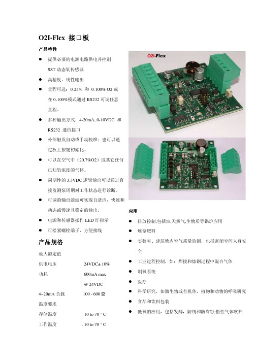
O2I-Flex 接口板产品特性提供必要的电源电路供电并控制SST动态氧传感器高精度、线性输出量程可选:0-25% 和0-100% O2或在0-100%模式通过RS232可调任意量程。
多种输出方式:4-20mA, 0-10VDC 和RS232 通信接口外部触发自动或手动校准;也可以通过板上按键初始化。
可以在空气中(20.7%O2)或其它任何已知氧浓度的气体。
周期性的3.3VDC逻辑输出可以通过直接监测泵周期对工作状态进行诊断。
可调的输出滤波可实现自适应,快速和动态或慢速且稳定的输出。
电源和传感器操作LED灯指示可松紧螺栓端子,方便接线产品规格最大额定值供电电压24VDC± 10%功耗600mA max@ 24VDC4~20mA负载100 - 600 Ω温度要求存储温度- 10 to 70 ° C工作温度- 10 to 70 ° C 应用排放控制,包括油,天然气,生物质等锅炉应用堆制肥料实验室、建筑物内空气质量监测,包括密闭空间人身安全工业过程控制,如:焊接和炼钢过程中混合气体制氧系统医疗科学研究,如微生物或有机体,植物和动物的呼吸研究 食品和饮料包装低氧的应用,包括发酵,防锈和防腐蚀,惰性气体吹扫O2I-Flex 接口板给电子元件提供必要的电源,控制SST 动态氧传感器可以用户设置量程0-25%和0-100%。
整个测量范围是线性的。
出厂默认是0-25%。
当配置0-100%量程时,客户可以定制模拟输出范围以符合实际应用。
输出可以配置为:4-20mA 和0-10VDC 或RS232接口3.3VDC 数字逻辑输出与电化学泵正常工作时的周期相同,因此,可以提供实时的传感器状态检测;若输出周期停止,传感器进入启动或故障状态。
这是预防故障操作。
数字输出也用来显示标定过程中接口板的状态。
板子上的1个绿色LED 灯指示了周期输出并使标定时检测传感器状态变得可视化。
红灯亮显示该模块已上电。


氧气瓶操作说明(总1页)
--本页仅作为文档封面,使用时请直接删除即可--
--内页可以根据需求调整合适字体及大小--
供氧器简单操作说明
1.检验氧气瓶内的储气量
a)顺时针旋转流量手轮,以关闭流量阀门。
b)逆时针旋转供氧手轮,以打开供氧阀门,观察氧压表的指示,此数值即为氧气瓶内氧气压力值。
c)顺时针旋转供氧手轮,以关闭供氧阀门;再逆时针旋转流量手轮,以打开流量调节阀;待氧压表和流量表都回到零位后,再顺时针旋转流量手轮,关闭流量阀门。
2.连接供氧器到呼吸机
a)用医用吸氧软管连接供氧器出气嘴及呼吸机低压氧供氧接口。
b)逆时针旋转供氧器供氧手轮以打开供氧阀门,再逆时针旋转流量手轮调节氧气流量(最大不超过10L/min)。
c)停止使用时,先关闭供氧器供氧阀门,再关闭流量阀门,以保证氧压表指针回到零位。
3.给供氧器充氧
a)用扳手取下供氧器充气口螺塞,用附带氧桥连接供氧器充气口及氧源接口(氧源压力不得超过15MPa),用扳手拧紧。
不允许在氧桥两端和出气嘴上加入任何非金属材料做垫圈。
b)关闭供氧器流量阀门,打开供氧阀门。
然后缓慢打开氧源供氧阀门,观察供氧器氧压表,通过调节氧源供氧阀门控制充氧速度,注意速度不宜过快。
c)待供氧器充满后(供氧器最大存储压力为±),先关闭氧源供氧阀门,在关闭供氧器供氧阀门,然后将氧桥取下。
取下氧桥后将供氧器充气口螺塞重新安装好并旋紧。
注:气瓶按国家有关规定,每三年进行一次定期检查,届时请与当地技术监督局联系。
2。

赛默飞离心机X1说明书
转速控制区:用上键设定增加离心转速;用下键设定降低离心转速;两键同时按下可切换设定位数。
时间控制区:用上键设定增加离心时间;用下键降低离心时间
(当时间设定为“0”时继续按下键会显示“HOLD”,表示不限时离心。
)
温度控制区:用上键设定增加离心温度:用下键设定降低离心温度。
开始/停止键:开始离心/停止离心 lid键:开启离心机封盖点动键:当某些实验样品仅仅需要短时间的离心可以按此按钮,按下时离心机转动,抬起即停止。
电子刹车键:用上键循环调节电子刹车档,共有9档。
(注意:当出现异常情况需要停机时,不要拔电源,只要将电子刹车调到9档并按下停止键)。
使用注意事项
1.使用前要确定离心腔内没有异物
2.使用前请确定转头已旋紧
3.要确定离心样品放置对称并且离心管放置到位。
4.离心前一定要确认转头盖旋紧
5.离心机使用结束后,请将转头取出。
6.离心机使用结束后,请保持机盖敞开以维持离心腔内的干
燥。
如不慎将腐蚀性液体遗留至离心腔内请及时清理。

便携供氧器的操作方法
便携式供氧器(Portable Oxygen Concentrator)的操作方法如下:
1. 首先确保便携供氧器的电池已经充满,或者已连接好外部电源。
2. 打开供氧器的电源开关,通常位于设备的顶部或侧面。
3. 调整氧气流量:根据医生的建议或个人需求,在供氧器上找到氧气流量调节器,通常是一个旋钮或按钮。
根据需要,调整流量大小,一般以升/分钟为单位。
4. 确保供氧器已连接好供氧管:找到供氧器上的连接口,插入供氧管的接头,并确保连接紧密。
5. 把供氧器背在身上或者将其放在平稳的表面上。
6. 插入鼻导管:将鼻导管的一端插入鼻孔中,确保插入深度适中,并与鼻孔紧密贴合。
7. 检查供氧器的运行状态:大多数便携供氧器会配备显示屏或指示灯,用于显示氧气浓度、电池电量等信息,确保供氧器正常运行。
8. 使用供氧器时,请将其放置在通风良好的区域,避免堵塞进气口。
9. 使用期间保持呼吸顺畅,避免吸入或呼出过大的气流。
10. 使用完毕后,关闭供氧器的电源开关,并拔掉电源连接线或取下电池。
请注意,以上仅为一般的操作方法,具体的操作步骤可能会因不同的供氧器型号而有所差异,因此在使用前请仔细阅读和理解设备的用户手册,并遵循医生或专业人员的指导。

易氧源制氧机使用说明
随着人们对健康的重视程度不断提高,制氧机作为一种能够提供纯净氧气的医疗设备,受到了越来越多人的关注和使用。
易氧源制氧机作为一种常见的制氧设备,其使用方法和注意事项对于用户来说至关重要。
下面将为大家介绍易氧源制氧机的使用说明。
1. 准备工作。
在使用易氧源制氧机之前,首先要确保设备的电源接通,并且放置在通风良好的地方。
同时,检查氧气管路是否连接牢固,氧气面罩或导管是否清洁无污染。
2. 开机操作。
接通电源后,按下开关按钮,易氧源制氧机开始工作。
在此过程中,要确保设备周围没有其他物品阻挡通风口,以免影响设备的散热效果。
3. 调节氧气流量。
根据医生或专业人士的建议,调节氧气流量,使其符合个人需求。
一般来说,氧气流量的调节范围是1-5升/分钟,但具体的流量
设置应根据个人情况而定。
4. 使用注意事项。
在使用易氧源制氧机时,需要注意以下几点:
避免将易氧源制氧机放置在潮湿或高温的环境中。
定期清洁和消毒氧气面罩或导管,以确保使用时的卫生和安全。
注意观察易氧源制氧机的工作状态,如发现异常情况及时关闭
设备并联系专业人士进行维修。
使用易氧源制氧机时,避免吸烟或在附近使用明火,以免引发
火灾。
5. 关机操作。
使用完毕后,先调节氧气流量至最小,然后再关闭易氧源制氧
机的电源。
总之,易氧源制氧机作为一种重要的医疗设备,其正确使用和维护对于患者的健康至关重要。
希望用户能够按照以上使用说明和注意事项正确操作易氧源制氧机,确保其稳定、安全地为您提供纯净的氧气。
卡默尔滴定x1pro使用教程
以下是卡默尔滴定x1pro使用教程:
1. 将卡默尔滴定x1pro取出,并插入电源插头。
开机时,屏幕会显示卡默尔标志和版本信息。
2. 准备溶液:按照实验需要,将需要滴定的样品制备好,并决定所使用的滴定试剂。
将试剂加入滴定瓶中,并用去离子水或其他合适的溶液配制好。
3. 准备样品:将样品加入滴定瓶中,并加入适量的指示剂。
指示剂的选择应根据试剂和样品的特性而定,以确保准确测定。
4. 连接电极:将电极插入滴定瓶中并固定。
确保电极与瓶底相接触,以获得准确读数。
5. 调整溶液体积:在开始滴定之前,需要根据样品的性质和试剂的浓度,调整滴定瓶中溶液的体积。
这可以通过手动或自动方式完成。
6. 开始滴定:启动卡默尔滴定x1pro的滴定程序,在屏幕上设置滴定参数,启动程序。
在进行滴定时,应注意滴定速率的控制和电极的稳定性,以确保准确测定。
7. 完成滴定:当指示剂颜色转变或电位跃变时,滴定完成。
记录所用滴定试剂的体积和计算出样品浓度。
8. 清洗电极:滴定完成后,应清洗电极,确保电极仍能正常使用。
以上就是卡默尔滴定x1pro使用教程的介绍,希望对您有所帮助。
3. Insert the battery and replace the coverCarefully connect the battery so the gold contacts connect with the row of connectors on the top left hand side of the Xda IQ (just below the camera lens). You can only fi t the battery one way and you shouldn’t need to use force. Gently press the battery down to secure it (there’ll be a small click as it’s locked into place).Slide the battery cover towards the camera lens then lightly snap into place.1. Open the rear coverRemove the rear cover by placing the phone in one hand with the keypad facing down in the palm of your hand. Press down on the back cover with your other hand and slide it open in the direction of the arrow.2. Insert your SIM cardOpen the SIM card door on the lower right. Insert the SIM card into the door with its gold-plated contacts facing down. Close the door and press down to lock it. Please be careful not to force any of the SIM reader components, as this may cause damage. It doesn’t take much pressure to insert the SIM correctly.Getting startedSmart IQ: it’s a good idea to charge the battery for at least eight hours before you use yourXda IQ for the fi rst time.4. Charge the batteryYou need to charge the batteryfully before using your Xda IQfor the fi rst time.Connect the AC charger to yourXda IQ and plug it into the wall.We recommend you use theAC adaptor the fi rst time youcharge your Xda IQ, and not thePC synchronisation cable.A solid amber light showsyour Xda IQ is being charged.This light will turn green whenthe battery is fully charged.5. Turn on and set upfor the fi rst timeTurn on your Xda IQ by pressingthe power button on the topleft-hand edge.Your Xda IQ will start to set itselfup and add settings supplied by O2.7. Synchronise with your PCBecause your Xda IQ is designed to complement your PC as a smartphone, you can work with the same information in both places. You can synchronise your Xda IQ with Microsoft® Outlook® on your PC. This will let you keep a copy of your address book, appointments and emails on both your Xda IQ and computer. Whenever you add appointments or write emails on your phone, you can copy them across to your PC each time you connect. This way, you’ll always have a back up copy of your information.6. Enter your PINWhen your Xda IQ restarts, it may ask you to enter the PIN for your SIM. All new connections to O 2 have a PIN on their SIM.Tap in your PIN and select Enter .If you’re an O2 Ireland customer, please enter the PUK code supplied with your SIM or call Customer Service on 1909.Smart IQ: you’ll block your SIM card if you enter the wrong PIN three times. This means you won’t be able to make or receive any calls, texts or picture messages. Don’t worry – you can easily sort this out by contacting your service provider. They’ll unblock it for you right away.To synchronise your Xda IQ with your Windows PC,you need to install Microsoft ActiveSync® 4.1. You’ll fi nd ActiveSync on the GettingStarted CD in your Xda IQ box, along with a copy of Microsoft Outlook 2002 and a single PC licence.After you’ve installed ActiveSync, connect the USB cable to your PC and Xda IQ, then follow the on-screen instructions to get synchronised.Now you’re set up, let’s get going.Status Meaning iconSearching for an accessible Wireless LAN hotspotConnected to a Wireless LAN hotspot New instant message in MSN Messenger New email, text or picture message(s)Phone is on with strong coverage Coverage is average Coverage is poorPhone is searching for a network to connect to Phone is switched offThere’s no network available to connect to, or no SIM in your XdaStatus Meaning icon Battery is fully charged Battery is only 20% fullYou’ll need to charge it soon Battery is nearly empty Battery is emptyYou’re connected to a foreign network (you’re roaming)You’re in an area of GPRS coverage You are connecting/connected to GPRS Battery is being chargedSpeakerphone is activeYou’ve missed a callVideo and picturesTake detailed pictures or shoot video with sound.The Xda IQ has a high-resolution camera and a clear high-quality colour screen.A world of connectionsWith onboard support for GPRS and Wireless LAN, you have several ways of connecting to the Internet at a range of speeds. Just choose what suits you and your location. Bluetooth means you’re wire free and can use your Xda IQ with car kits and headsets.Work more convenientlyThe Xda IQ is one of the most powerful connected handhelds available. It gives you more control over the way you work – and where you work. It keeps you in touch wherever you go. You can access contact information, browse the web, send emails, track appointments and much more.Mobile phoneMake and receive calls to keep in contact. Get in touch with the offi ce, or send text messages.Internet and messagingUse Outlook Mobile to send and receive emails with attachments, keep track of meetings and events, and keep in sync with Outlook on your PC. Compose and send picture messages or text your contacts for a speedy response.Internet Explorer Mobile gives you fast connection to the Internet. Do your banking, check your market prices or catch up with the day’s news.Using itIn the boxXda IQyour all-in-one phone and hand-held PCXda IQ batteryto power your phoneXda IQ caseto protect and carry your phoneApplication CDClearVue Document Suite,Wireless Modem USB DriverMicrosoft Windows MobileGetting Started CDincluding ActiveSync andOutlook 2002Warranty card for EuropeConnection cableto connect your Xda to your PC Microsoft Windows Mobile 5.0 user guideHandsfree stereo headsetO may change the contents of the Xda IQ box in the future. The images hereare purely to illustrate what’s in the box; the actual contents may look slightly different.Quick Start Guidethis bookletAC adaptorto charge your Xda IQ2223Help and troubleshootingHelp onlineNeed technical help with your Xda IQ? No problem. Send an email to our support team:(UK)********************(EIRE)*************We will try to get back to you within 24 hours or on the next business day.Talk to usIf you have any generalquestions about your Xda IQ, your service provider will be able to help. You’ll fi nd their contact details printed on your monthly bill. If you’re a corporate customer, we recommend you contact your internal help desk.Need to ask about charges on your account or services not activated? Please contact the service provider where you bought your phone from.Smart IQ: our technical support team can only help you with how touse your Xda IQ.When I’m overseas, why do I see a white triangle at the top of the screen? The triangle means you’re roaming on a foreign network and roaming charges apply. Can I close applications using one of the buttons? Press the End call key. Smart IQ: to fi nd out more, check out/xdaGeneral questionsCan I use software designed for the Xda sp with my Xda IQ?Xda IQ uses Microsoft Windows Mobile 5.0 as the core system. Applications written for the Xda sp may not work correctly. You should contact the software vendor to checkif the application will work correctly with Windows Mobile 5.0.Can I receive phone callsor text messages whileusing the Internet orsynchronising emailon my Xda IQ?You can make and receive phonecalls when using Wireless LAN.If you’re actively using yourconnection in GPRS mode, yourphone calls will be forwardedbased on your settings – thedefault is to divert to voicemail(if it’s set up) or another number.However, you can make andreceive calls if your GPRS is idle.What are the maximumspeeds of GPRS?In GPRS mode, Xda IQ supportsa maximum download speed ofabout 53kbps and an uploadspeed of 26kbps.How do I turn thephone off and gointo PDA mode?Press the power button atthe top left edge of the phone,and select fl ight mode.2425。
OPERATOR’S MANUAL SX20X-XXX-XXX-AXXXXINGERSOLL RAND COMPANY LTD209 NORTH MAIN STREET – BRYAN, OHIO 43506✆ (800) 495-0276 • FAX (800) 892-6276© 2015CCN 47521457001INCLUDING: OPERATION, INSTALLATION & MAINTENANCERELEASED: 11-28-14REVISED: 10-16-15(REV: B)2” FDA SANITARY DIAPHRAGM PUMPSERVICE KITSRefer to Model Description Chart to match the pump material options.637494-XX for fluid section repair kits information (see page 4). NOTE : This kit also contains several air motor seals which will need to be replaced.637497-X for air section repair (see page 6).637498-X for major air valve assembly (see page 8 & 9).PUMP DATAModels ................. see Model Description Chart for “-XXX”.Pump Type ............. Metallic Air Operated Double Diaphragm Material ................ see Model Description Chart Weight ...............SX20S-XXX-XXX-AXXXX ......... 166.45 lbs (75.5 kgs)SX20R-XXX-XXX-AXXXX ......... 141.76 lbs (64.3 kgs) Maximum Air Inlet Pressure ........120 psig (8.3 bar)Maximum Material Inlet Pressure ... 10 psig (0.69 bar)Maximum Outlet Pressure .......... 120 psig (8.3 bar)Maximum Flow Rate ................ 195 gpm (738 lpm)Displacement / Cycle @ 100 psig .... 1.3 gal. (4.9 lit.)Maximum Particle Size ............. 1/4” dia. (6.4 mm)Maximum Temperature Limits (diaphragm / ball / seal material)Santropene® ................... -40° to 225° F (-40° to 107° C)PTFE ........................... 40° to 225° F (4° to 107° C)Dimensional Data ................... s ee page 8Mounting Dimension ............... s ee page 8Noise Level @ 70 psig, 60 cpm ....... 82.5 dB(A)①① The pump sound pressure levels published here have been updated to an Equivalent Continuous Sound Level (LA eq ) to meet the intent of ANSI S1.13-1971, CAGI-PNEUROP S5.1 using four microphone locations.NOTICE: All possible options are shown in the chart, however, certain combinations may not be recommended, consult a representative or thefactory if you have questions concerning availability.MODEL DESCRIPTION CHARTPortC - Sanitary FlangeFluid Caps & Manifold Material S - 316L Stainless Steel Ball MaterialM - Medical Grade Santoprene T - PTFEHardware Material S - Stainless Steel Diaphragm MaterialM - Medical Grade Santoprene T - PTFE / Santoprene Seat MaterialS - 316L Stainless Steel Center Section Material R - White Polypropylene S - Stainless Stell SD20 X - C S S - S X X - AFluid Section Service Kit Selection SX20X-XXX-XXX-AXXXX Example: Models SD20S-CSS-S M M-A 637494- X XFluid Section Service Kit # 637494-MMBallDiaphragm Model Revision A - RevisionPage 2 of 12 SX20X-XXX-XXX-AXXXX (en)EXCESSIVE AIR PRESSURE STATIC SPARKWARNING EXCESSIVE AIR PRESSURE. Can cause personalinjury, pump damage or property damage.Do not exceed the maximum inlet air pressure as stated on the pump model plate.Be sure material hoses and other components are able to withstand fluid pressures developed by this pump. Check all hoses for damage or wear. Be certain dispensing device is clean and in proper working condition.WARNING STATIC SPARK. Can cause explosion resulting in severe injury or death. Ground pump and pumping system.Sparks can ignite flammable material and vapors.The pumping system and object being sprayed must begrounded when it is pumping, flushing, recirculating or spraying flammable materials such as paints, solvents, lacquers, etc. or used in a location where surrounding atmosphere is conducive to spontaneous combustion. Ground the dispensing valve or device, containers, hoses and any object to which material is being pumped.Secure pump, connections and all contact points to avoid vibration and generation of contact or static spark.Consult local building codes and electrical codes for spe-cific grounding requirements.After grounding, periodically verify continuity of electrical-path to ground. Test with an ohmmeter from each compo-nent (e.g., hoses, pump, clamps, container, spray gun, etc.) to ground to ensure continuity. Ohmmeter should show 0.1 ohms or less.Submerse the outlet hose end, dispensing valve or device in the material being dispensed if possible. (Avoid free streaming of material being dispensed.)Use hoses incorporating a static e proper ventilation.Keep inflammables away from heat, open flames and sparks.Keep containers closed when not in use.WARNING Pump exhaust may contain contaminants. Can cause severe injury. Pipe exhaust away from work area and personnel.In the event of a diaphragm rupture, material can be forced out of the air exhaust muffler.Pipe the exhaust to a safe remote location when pumping hazardous or inflammable materials.Use a grounded 3/8” minimum i.d. hose between the pump and the muffler.WARNING HAZARDOUS PRESSURE. Can result in serious injury or property damage. Do not service or clean pump, hoses or dispensing valve while the system is pressurized.Disconnect air supply line and relieve pressure from the system by opening dispensing valve or device and / orcarefully and slowly loosening and removing outlet hose or piping from pump.WARNING jury or property damage. Do not attempt to return a pump to the factory or service center that contains hazardous material. Safe handling practices must comply with local and national laws and safety code requirements.Obtain Material Safety Data Sheets on all materials from the supplier for proper handling instructions.•••••••••••••••••WARNING minum parts cannot be used with 1,1,1-trichloroethane, methylene chloride or other halogenated hydrocarbon solvents which may react and explode.Check pump motor section, fluid caps, manifolds and all wetted parts to assure compatibility before using with solvents of this type.WARNING terials must be FDA compliant and meet the United States Code of Federal Regulations (CFR) Title 21, Section 177.CAUTION wetted parts and the substance being pumped, flushed or recirculated. Chemical compatibility may change with temperature and concentration of the chemical(s) within the substances being pumped, flushed or circulated. For specific fluid compatibility, consult the chemical manufac-turer.CAUTION cal stress only. Certain chemicals will significantly reduce maximum safe operating temperature. Consult the chemi-cal manufacturer for chemical compatibility and tempera-ture limits. Refer to PUMP DATA on page 1 of this manual.CAUTION been trained for safe working practices, understand it’s limitations, and wear safety goggles / equipment when required.CAUTION of the piping system. Be certain the system components are properly supported to prevent stress on the pump parts.Suction and discharge connections should be flexible connections (such as hose), not rigid piped, and should be compatible with the substance being pumped.CAUTION not allow pump to operate when out of material for long periods of time.Disconnect air line from pump when system sits idle for long periods of time.CAUTION sure compatible pressure rating and longest service life.NOTICE RE-TORQUE ALL FASTENERS BEFORE OPERATION. Creep of housing and gasket materials may cause fasteners to loosen. Re-torque all fasteners to ensure against fluidor air leakage.NOTICE For best sealing results, use a standard sanitary clamp style gasket of a flexible material such as EPDM, Buna-N, fluoroelastomer, or silicone.NOTICE SANITIZE THE PUMP BEFORE FIRST USE. It is the user’s responsibility to properly sanitize the pump before first use. It is up to the user whether this will include disas-sembling and cleaning individual parts or simply flushing pump with a sanitizing solution.WARNINGCAUTION NOTICE •••OPERATING AND SAFETY PRECAUTIONSREAD, UNDERSTAND AND FOLLOW THIS INFORMATION TO AVOID INJURY AND PROPERTY DAMAGE.SX20X-XXX-XXX-AXXXX (en) Page 3 of 12• Loctite® is a registered trademark of Henkel Loctite Corporation •• Santoprene® is a registered trademark of Monsanto Company, licensed to Advanced Elastomer Systems, L.P . • ARO® is a registered trademark of Ingersoll Rand Company •• Lubriplate® is a registered trademark of Lubriplate Division (Fiske Brothers Refining Company) • 262™, 271™ and 572™ are trademarks of Henkel Loctite Corporation •GENERAL DESCRIPTIONThe ARO diaphragm pump offers high volume delivery even at low air pressure and a broad range of material compatibility options are available. Refer to the model and option chart. ARO pumps feature stall resistant design, modular air motor / fluid sec-tions.Air operated double diaphragm pumps utilize a pressure differen-tial in the air chambers to alternately create suction and a positive fluid pressure in the fluid chambers, valve checks ensure a positive flow of fluid.Pump cycling will begin as air pressure is applied and will continue to pump and keep up with the demand. It will build and maintain line pressure and will stop cycling once maximum line pressure is reached (dispensing device closed) and will resume pumping as needed.AIR AND LUBE REQUIREMENTSWARNING age, personal injury or property damage.A filter capable of filtering out particles larger than 50 microns should be used on the air supply. There is no lubrication re-quired other than the “O” ring lubricant which is applied during assembly or repair.If lubricated air is present, make sure that it is compatible with the “O” rings and seals in the air motor section of the pump.INSTALLATIONVerify correct model / configuration prior to installation.Retorque all external fasteners per specifications prior to start up.Pumps are tested in water at assembly. Flush pump with com-patible fluid prior to installation.When the diaphragm pump is used in a forced-feed (flooded inlet) situation, it is recommended that a “Check Valve” be installed at the air inlet.Material supply tubing should be at least the same diameter as the pump inlet manifold connection.Material supply hose must be reinforced, non-collapsible type compatible with the material being pumped.Piping must be adequately supported. Do not use the pump to support the piping.Use flexible connections (such as hose) at the suction and dis-charge. These connections should not be rigid piped and must be compatible with the material being pumped.Secure the diaphragm pump legs to a suitable surface (level and flat) to ensure against damage by vibration.Pumps that need to be submersed must have both wet and non-wet components compatible with the material being pumped.Submersed pumps must have exhaust pipe above liquid level. Exhaust hose must be conductive and grounded.Flooded suction inlet pressure must not exceed 10 psig (0.69 bar).••••••••••••••OPERATING INSTRUCTIONSAlways flush the pump with a solvent compatible with the material being pumped if the material being pumped is subject to “setting up” when not in use for a period of time.Disconnect the air supply from the pump if it is to be inactive for a few hours.PARTS AND SERVICE KITSRefer to the part views and descriptions as provided on pages 4 through 7 for parts identification and service kit information.Certain ARO “Smart Parts” are indicated which should be avail-able for fast repair and reduction of down time.Service kits are divided to service two separate diaphragm pump functions: 1. AIR SECTION, 2. FLUID SECTION. The Fluid Section is divided further to match typical part MATERIAL OP-TIONS.MAINTENANCEProvide a clean work surface to protect sensitive internal moving parts from contamination from dirt and foreign matter during service disassembly and reassembly.Keep good records of service activity and include the pump in preventive maintenance program.Before disassembling, empty captured material in the outlet manifold by turning the pump upside down to drain material from the pump.FLUID SECTION DISASSEMBLYRemove (61) outlet manifold and (60) inlet manifold.Remove (22) balls, (19) “O” rings and (21) seats..Remove (15) fluid caps.NOTE: Only PTFE diaphragm models use a primary (7) diaphragm and a backup (8) diaphragm. NOTE: Do not stretch or bend the clamp during disassembly. Loosen the fastener to free the clamp and move the clamp to the air cap side of the pump to remove the fluid cap.4. Remove the (14) screw, (6) diaphragm washer, (7) or (7 / 8) diaphragms, and (5) backup washer.NOTE: Do not scratch or mar the surface of (1) diaphragm rod.FLUID SECTION REASSEMBLYReassemble in reverse order. Refer to the torque requirements on page 5.Clean and inspect all parts. Replace worn or damaged parts with new parts as required.Lubricate (1) diaphragm rod and (144) “U” cups with Lubriplate® FML-2 grease (94276 grease packet is included in service kit).For models with PTFE diaphragms: Item (8) Santoprene dia-phragm is installed with the side marked “AIR SIDE” towards the pump center body. Install the (7) PTFE diaphragm with the side marked “FLUID SIDE” towards the (15) fluid cap.Examine torque settings after the pump has been re-started and run a while.•••••••1.2.3.•••••Page 4 of 12 SX20X-XXX-XXX-AXXXX (en)MATERIAL CODE[B ] = Nitrile[C] = Carbon Steel [Co] = Copper[MSp] = Medical Grade Santoprene [SP] = Santoprene [SS] = Stainless Steel [T] = PTFE❷ ❸ Items included in Air motor kit parts, see pages 6. 8 and 9.❶ 637494-XX FLUID SECTION SERVICE KITS INCLUDE: BALLS (See �Ball Options”, refer to -XX Service kit in chart below), DIAPHRAGMS (See �Diaphragm Options”, refer to -XX in Service kit chart below), and items 19, 70, 144, 175, (listed below) plus 174 and 94276 Lubriplate FML-2grease (page 6).144�144�SX20X-XXX-XXX-AXXXX (en) Page 5 of 12Page 6 of 12SX20X-XXX-XXX-AXXXX (en)Indicates parts included in 637497-1 Air Section Service Kit for shown below and items (70), (144), (175) and (180) shown on page 4.MATERIAL CODE[B] = Nitrile [Sp] = Santoprene [Br] = Brass [SS] = Stainless Steel [Ck] = Ceramic [U] = Polyurethane[D] = Acetal[P] = PolypropyleneSX20X-XXX-XXX-AXXXX (en) Page 7 of 12AIR MOTOR SECTION SERVICEService is divided into two parts - 1. Pilot Valve, 2. Major Valve.GENERAL REASSEMBLY NOTES:Air Motor Section service is continued from Fluid Section repair.Inspect and replace old parts with new parts as necessary. Look for deep scratches on metallic surfaces, and nicks or cuts in “O” rings.Take precautions to prevent cutting “O” rings upon installation.Lubricate “O” rings with Lubriplate FML-2 grease.Do not over-tighten fasteners. Refer to torque specification block on view.Re-torque fasteners following restart.SERVICE TOOLS - To aid in the installation of (168) “O” rings onto the (167) pilot piston, use tool # 204130-T, available from ARO.PILOT VALVE DISASSEMBLYA light tap on (118) actuator pin should expose the opposite (121) sleeve, (167) pilot piston and other parts.Remove (170) sleeve. Inspect inner bore of sleeve for damage.PILOT VALVE REASSEMBLYClean and lubricate parts not being replaced from service kit.Install new (171 and 172) “O” rings. Replace (170) sleeve.Install new (168) “O” rings and (169) “U” Cup. NOTE : Lip direction. Lubricate and replace (167) pilot piston.Reassemble remaining parts. Replace (173 and 174) “O” rings.•••••••1.2.1.2.3.4.MAJOR VALVE DISASSEMBLYRemove (135) valve housing and (233) adapter plate, exposing (132) and (166, where applicable) gaskets, (146 and 147) “O” rings and (176) diaphragms.Remove (233) adapter plate, releasing (140) valve insert, (141) valve plate, (199, 200) and (241, where applicable) gaskets and (243 and 244) or (146, 147 and 232, where applicable)“O”rings.Remove (136) end cap and (137) “O” ring, releasing (111) spool.MAJOR VALVE REASSEMBLYInstall new (138 and 139) “U” cups on (111) spool - NOTE: LIPS MUST FACE EACH OTHER.Insert (111) spool into (135) valve housing.Install (137) and (242, where applicable) “O” rings on (136) end cap and assemble end cap to (135) valve housing, securing with (107) end plates (where applicable) and (105) screws.Install (140) valve insert, (141) valve plate, (199) gasket and (243 and 244, where applicable) “O“ rings into (135) valve housing. NOTE : Assemble (140) valve insert with “dished” side toward (141) valve plate. Assemble (141) valve plate without dots iden-tification toward (140) valve insert.Assemble (146, 147 and 232, where applicable) “O” rings, (200) and (241 or 199, where applicable) gaskets and (233) adapter plate to (135) valve housing, securing with (240) screws.Assemble (132) and (166, where applicable) gaskets, (146 and 147, where applicable) or (232, where aaplicable) “O” rings and (176) checks to (101)center body.Assemble (135) valve housing and components to (101) center body, securing with (134)screws and (133) washers.1.2.3.1.2.3.4.5.6.7.Page 8 of 12 SX20X-XXX-XXX-AXXXX (en)169�147�����176 �A replacement major valve service assembly is available separately, which includes the following:637498 for models SX20S-XXX-XXX-AXXXX: 105 (4), 111, 128 , 132, 135, 136, 137, 138, 139, 140, 141, 146, 147 (2), 176 (2), 200 and 233.LUBRICATION / SEALANTS★ Apply Lubriplate FML-2 grease to all �O” rings, �U” cups and mating parts.⏹ Apply PTFE tape to threads at assembly. Apply anti-seize compound to threads at assembly.☞ ASSEMBLY TORQUE REQUIREMENTS ☜NOTE: DO NOT OVERTIGHTEN FASTENERS.ALL FASTENERS ARE METRIC.For SX20S-XXX-XXX-AXXXX:(105) Screw, 40 - 50 in. lbs (4.5 - 5.6 Nm).(134) Screw, 40 - 50 in. lbs (4.5 - 5.6 Nm).(240) Screw, 40 - 50 in. lbs (4.5 - 5.6 Nm).SX20X-XXX-XXX-AXXXX (en) Page 9 of 12A replacement major valve service assembly is available separately, which includes the following:637498-1 for models SX20R-XXX-XXX-AXXXX: 105 (4), 107 (2), 111, 132, 135, 136, 137, 138, 139, 140, 141, 146, 147, 166, 176 (2), 199, 200, 232(2), 233 and 236 (4).LUBRICATION / SEALANTS★ Apply Lubriplate FML-2 grease to all �O” rings, �U” cups and mating parts. Apply anti-seize compound to threads at assembly.☞ ASSEMBLY TORQUE REQUIREMENTS ☜NOTE: DO NOT OVERTIGHTEN FASTENERS.ALL FASTENERS ARE METRIC.For SX20R-XXX-XXX-AXXXX:(105) Screw, 35 - 40 in. lbs (4.0 - 4.5 Nm).(134) Screw, 35 - 40 in. lbs (4.0 - 4.5 Nm).MAJOR VALVE136107236138 �111139 �137��� 134135133141 �199 �140233132�176 �232�146 �147 �166�232��� 105107200�� 174121� 173167168 �� 169172 �171 �170121174 �173 �118PILOT VALVE PART GROUP103101201127Figure 4Page 10 of 12 SX20X-XXX-XXX-AXXXX (en)DIMENSIONAL DATAProduct discharged from exhaust outlet.Check for diaphragm rupture.Check tightness of (14) diaphragm screw.Air bubbles in product discharge.Check connections of suction plumbing.Check “O” rings between intake manifold and inlet side fluid caps.Check tightness of (14) diaphragm screw.Motor blows air or stalls.Check (176) check valve for damage or wear.Check for restrictions in valve / exhaust.•••••••Low output volume, erratic flow or no flow.Check air supply.Check for plugged outlet hose.Check for kinked (restrictive) outlet material hose.Check for kinked (restrictive) or collapsed inlet material hose.Check for pump cavitation - suction pipe should be sized at least as large as the inlet thread diameter of the pump for proper flow if high viscosity fluids are being pumped. Suction hose must be a non-collapsing type, capable of pulling a high volume.Check all joints on the inlet manifolds and suction connections. These must be air tight.Inspect the pump for solid objects lodged in the diaphragm chamber or the seat area.•••••••TROUBLESHOOTINGSX20X-XXX-XXX-AXXXX (en) Page 11 of 12PN 97999-1722 Page 12 of 12 SX20X-XXX-XXX-AXXXX (en)。