ap03_sg_macro_b_26593
- 格式:pdf
- 大小:237.36 KB
- 文档页数:8

华三AP WA1208E瘦转胖命令行失败后 bootware 重新刷机实际操作成功记录启动时按Ctrl+B 进入bootware模式|<3> Delete File ||<0> Exit To Main Menu | ============================================================================Enter your choice(0-3): 3 【bootware模式下按3删除已经上传的文件】Deleting the file in flash:'M' = MAIN 'B' = BACKUP 'S' = SECURE 'N/A' = NOT ASSIGNED============================================================================|NO.Size(B) Time Type Name ||1 6599560 Apr/26/2000 13:12:10 N/A wa1208e-cmw520-r1112p15-fa~001 ||2 232 Apr/26/2000 12:02:14 N/A private-data.txt ||3 418 Apr/26/2000 12:02:18 N/A startup.cfg ||0 Exit |============================================================================Enter file No:1 【按1删除已经上传的没有改名的bin文件】The file you selected is flash:/wa1208e-cmw520-r1112p15-fat.bin,Delete it? [Y/N]YDeleting.......Done!==============================================================|Note:the operating device is flash ||<1> Display All File(s) ||<2> Set Application File type ||<3> Delete File ||<0> Exit To Main Menu | ===================================================== Enter your choice(0-3): 0======================================================|<1> Boot System ||<2> Enter SerialSubMenu ||<3> Enter Ethernet SubMenu ||<4> File Control ||<5> Modify BootWare Password ||<6> Skip Current System Configuration ||<7> BootWare Operation Menu ||<8> Clear Super Password ||<9> Storage Device Operation ||<0> Reboot |============================================================================Enter your choice(0-9): 0System is starting...Booting Normal Extend BootWare....The Extend BootWare is self-decompressing..................................Done!***************************************************************************** ** H3C WA1208E BootWare, Version 3.08 ** *****************************************************************************Copyright (c) 2004-2010 Hangzhou H3C Technologies Co., Ltd. Compiled Date : Jul 12 2010CPU Type : IXP422CPU L1 Cache : 32KBCPU Clock Speed : 266MHzMemory Type : SDRAMMemory Size : 64MBMemory Speed : 133MHzBootWare Size : 512KBFlash Size : 8MBBootWare Validating...Press Ctrl+B to enter extended boot menu...Please input BootWare password:Note: The current operating device is flashEnter < Storage Device Operation > to select device.======================================================|<1> Boot System ||<2> Enter Serial SubMenu ||<3> Enter Ethernet SubMenu ||<4> File Control ||<5> Modify BootWare Password ||<6> Skip Current System Configuration|<7> BootWare Operation Menu ||<8> Clear Super Password ||<9> Storage Device Operation ||<0> Reboot |============================================================================Enter your choice(0-9): 3 【<3>进入以太网子菜单| 】====================================================|Note:the operating device is flash ||<1> Download Application Program To SDRAM And Run ||<2> Update Main Application File ||<3> Update Backup Application File ||<4> Update Secure Application File ||<5> Modify Ethernet Parameter ||<0> Exit To Main Menu| |============================================================================Enter your choice(0-5): 2 【应该先按<5>做好设置Modify Ethernet Parameter 前面按2就错了所以要重复上面的步骤选3选5设置tftp地址】Loading...System is starting...Booting Normal Extend BootWare....The Extend BootWare is self-decompressing..................................Done!***************************************************************************** ** H3C WA1208E BootWare, Version 3.08 ** *****************************************************************************Copyright (c) 2004-2010 Hangzhou H3C Technologies Co., Ltd. Compiled Date : Jul 12 2010CPU Type : IXP422CPU L1 Cache : 32KBCPU Clock Speed : 266MHzMemory Type : SDRAMMemory Size : 64MBMemory Speed : 133MHzBootWare Size : 5Flash Size : 8MBBootWare Validating...Press Ctrl+B to enter extended boot menu...Please input BootWare password:Note: The current operating device is flashEnter < Storage Device Operation > to select device.======================================================|<1> Boot System ||<2> Enter Serial SubMenu ||<3> Enter Ethernet SubMenu|<4> File Control ||<5> Modify BootWare Password ||<6> Skip Current System Configuration ||<7> BootWare Operation Menu ||<8> Clear SuperPassword ||<9> Storage Device Operation ||<0> Reboot============================================================================Enter your choice(0-9): 3====================================================|Note:the operating device is flash ||<1> Download Application Program To SDRAM And Run ||<2> Update Main Application File ||<3> Update Backup Application File ||<4> Update Secure Application File ||<5> Modify Ethernet Parameter ||<0> Exit To Main Menu | | |============================================================================Enter your choice(0-5): 5====================================================|Note: '.' = Clear field. |..The Extend BootWare is self-decompressi| '-' = Go to previous field. |one!*****************************| Ctrl+D = Quit. |*============================================================================记住网线要直连pc 设置tftp时一定要在一个网段就是这两个Server IP Address :192.168.1.100Local IP Address :192.168.1.50############################################################################### #############################【这里还有一项在设置ip之前还要输入wa1208_fat.bin 下面一行也是。

Google Pixel 6 Pro 128GBGoogle Tensor Application Processor PoP(Tensor AP + Micron 12 GB LPDDR5 MT62F1536M64D8CH-031 WT:A)Kioxia 128 GB NAND Flash MemorySamsung SHANNON A5123 5G ModemSamsung SHANNON 5511 RF TransceiverMaxim MAX77759A PMICSTMicroelectronics NFC Controller ST54KMaxim MAX20339EWB Surge protection ICNXP PCA9468 Battery Charger ICSTMicroelectronics MCU ST33J2M0Google H1D3M Titan M security processorSamsung Exynos SM 5800 Supply Modulator (2 pcs)Cirrus Logic CS35L41B Audio Amplifier (2 pcs)Cirrus Logic CS40L25 Audio Amplifier HapticBroadcom BCM47765 GNSS Receiver ICFigure 1. Google Pixel 6 Pro Board ShotSkyworks SKY53737 FEMSkyworks SKY58260-11 FEMSamsung Exynos SM 5800 Supply ModulatorQorvo QM77080 FEMSkyworks SKY53738 FEM (3 pcs)Skyworks SKY77652-31 PAMSamsung Shannon 5311A PMICIDT P9412 Wireless Charing Receiver ICSamsung PMIC S2MPG10Samsung PMIC S2MPG11Unknown, Wi-Fi/BT Module (likely)Figure 2. Google Pixel 6 Pro Board ShotGoogle Tensor Application ProcessorGoogle’s semi-custom application processor is all about AI. Google built a custom deep learning accelerator (DLA) to challenge Qualcomm and Samsung in inferencing. The custom DLA features 16 (4x4) instantiations of systo lic arrays that outscore both Qualcomm and Samsung on ETH Zurich’s AI-Benchmark. While impressive, AI-Benchmark only tells half the story since it heavily relies on FP16 for inferencing. Most mobile AI network designers like to use INT8 for their layers because of the increased energy efficiency and comparable accuracy. For INT8 processing, the Pixel’s DLA lags both Qualcomm and Samsung in object detection, image segmentation, and image classification according to MLPerf 1.0.1 results.Figure 3. Google Deep Learning Accelerator (DLA)TechInsights' lab team has done a great job in getting the Google Tensor processor die photos quickly. The Tensor die has a die size (seal) of 10.38mm x 10.43mm = 108.26mm2 and is fabbed on Samsung's5nm process node technology. The following images show die marks and the die photo.Figure 4. Google Tensor Die MarkingsFigure 5. Google Tensor Package MarkingsThe die mark “S5P9845” conforms to the traditional Samsung Exynos processor naming rule, where the Exynos 990 Application Processor has the die marks of S5E9830, the Exynos 2100 5G SoC has die marks of S5E9840, and the Exynos 1080 5G SoC has S5E9815.We have heard of possible ties between the Google Tensor and Samsung Exynos processors, and our analysis of the Tensor die continues. It does appear that the foundry supplier for the Tensor die is Samsung. We will confirm the process node soon, which we ex pect is in Samsung’s 5LPE.Figure 6. Google Tensor Die PhotoSecurityGoogle designed the Titan M2, which is a custom RISC-V controller, to support Android Strongbox, securely generating keys, storing passwords, and protecting PINs. The company tested and certified its Titan chip through an external evaluation lab, achieving AVA_VAN.5 certification—one of the highest levels for smartphones.Mobile RF Components in the Google Pixel 6 ProOn the mobile RF front, the Pixel 6 brings about some key new developments:∙Google / Samsung ties in the Tensor: Now that we have spent some time examining the Google Tensor SoC, we have analyzed the device tree file system of the Linux kernel for Google Pixel 6, and it shows that some blocks of the Google GS101 Tensor processor are shared with Samsung’s Exynos.∙ A first for the US market: Samsung has developed a full 5G radio solution, which is included in the Pixel 6, making this the first major 5G phone in the US that does not include a Qualcommmodem.Looking forward, we note that Oppo is looking to develop their own SoC solutions for higher end phones - is Qualcomm’s dominance in this space diminishing?UWB ConnectivityConfirmed: the Google Pixel 6 Pro supports UWB connectivity, operating between 6489.6 MHz and 7987.2 MHz. Similar to the Galaxy S21 Ultra UWB design, the Google Pixel 6 Pro has multiple UWB patch antennas. However, in Google Pixel 6 Pro, only one antenna is used to transmit, whereas in the Galaxy S21 Ultra, two UWB antennas are used to send UWB signals.Although the Google Pixel 6 Pro design has similar components to the Samsung Galaxy S20 and Galaxy S21 Ultra, the Teardown team identified a new Qorvo UWB component instead of the same NXP SR100T that was found in the Samsung Galaxy S21 Ultra.WiFi 6EAnother point of similarity between the Google Pixel 6 Pro and the Samsung Galaxy S21 Ultra: the Pixel supports WiFi 6. This, however, is not just a protocol advancement - it requires new hardware designs. So far, we can confirm that the WiFi 6E modules from both phones include the Broadcom WiFi 6E SoC.Samsung Design WinsWith the exception of the Google Tensor Application Processor - which is now in our , the phone's key components are from Samsung, including: Samsung SHANNON A5123 5G Modem, Samsung SHANNON 5511 RF Transceiver, SHANNON 5800 Envelope Tracker IC, Samsung SHANNON 5311A PMIC, And more! The Samsung SHANNON A5123 5G Modem is not new to us. We originally found it in the Galaxy S20 Ultra in early 2020, where it paired with the Samsung Exynos 990 Application Processor as a standalone 5G Modem.As we have confirmed that there is a standalone Samsung 5G Modem in the Pixel 6 Pro, it stands to reason that the Google Tensor is an Application Processor without integrated Modem functionality, but we have not seen the die photos yet - we will confirm when we do.The Samsung SHANNON 5511 RF Transceiver is not new to us either. We originally found it in Samsung Exynos 1080 and 2100 5G SoC platform smartphones, such as Vivo X60 and Samsung Galaxy S21 series in early 2021.Additional Design WinsIn Memory, the Google Pixel 6 Pro we have torn down has a Micron 12 GB LPDDR5 which should have 8 pieces die of Micron’s 1y nm 12 Gb LPDDR5.KIOXIA has won the NAND Flash slot.There is a standalone GNSS Receiver IC from Broadcom. The BCM47765 is the company’s second generation Dual-Frequency (L1+L5) GNSS chip. TechInsights has analyzed the first generationBCM47755.The Pixel 6 Pro supports NFC and Wi-Fi/BT functions too. We have identified two likely modules and will confirm them through further analysis.STMicroelectronics keeps the NFC slot design win with the same die that we have seen in the Google Pixel 4 and Pixel 4 XL. We have confirmed that inside the wireless combo IC module is the Broadcom BCM4389 Wi-Fi 6E and Bluetooth 5 wireless combo SoC, which we first saw in the Samsung Galaxy S21 Ultra 5G phone.Google Pixel 6 Pro US Model GA03149-USWe have now done a quick tear down on a Google Pixel 6 Pro GA03149-US, a United States model of the phone that supports 5G mmWave and Sub-6.Comparison with the Canadian model we have been examining shows that the US model has a Samsung mmWave RF Transceiver Exynos RF 5710. So Samsung is the second silicon supplier of the 5G NR mmWave cellular chipsets, alongside Qualcomm. TechInsights will be creating a series of reverse engineering reports on the Exynos RF 5710 for our Mobile RF Analysis subscribers.We have also found a Murata mmWave Module SS1707051 found in the US phone. We are currently working to identify the die inside.Figure 7. Samsung mmWave RF Transceiver Exynos RF 5710Figure 8. Dual mmWave antenna module from Murata。

DD WRT目录DD WRT (1)Supported Devices (3)[edit]3com (3)[edit]Abocom (3)[edit]Accton (4)[edit]Aceex (4)[edit]Actiontec (4)[edit]ADI Engineering (4)[edit]Airlink 101 (5)[edit]Airlive / Ovislink (5)[edit]Alfa Networks (6)[edit]Allnet (6)[edit]Anaptyx Wireless Dynamics (7)[edit]Arada Systems (8)[edit]Askey (8)[edit]Asus (8)[edit]Belkin (11)[edit]Bountiful (13)[edit]Browan (13)[edit]Buffalo (13)[edit]Cisco (16)[edit]Conceptronic (22)[edit]Compex (23)[edit]Conrad Elektronic (27)[edit]Corega (27)[edit]Dell (28)[edit]Devolo (28)[edit]Digitus (29)[edit]D-Link (29)[edit]Doodle Labs (31)[edit]Dynex (31)[edit]Edimax (31)[edit]Encore (32)[edit]EnGenius (32)[edit]Exel Networks (32)[edit]Fluidmesh (32)[edit]FON (33)[edit]Fry's Electronics (33)[edit]Gateway (34)[edit]Gateworks (34)[edit]Intellinet (Reichelt) (36)[edit]Iomega (36)[edit]JJPlus (36)[edit]Lanready (37)[edit]Linksys (38)[edit]Logilink (38)[edit]MagicBox (38)[edit]Meraki (38)[edit]Microsoft (39)[edit]Mikrotik Routerboard (39)[edit]Mitsubishi (39)[edit]Motorola (40)[edit]MSI (40)[edit]MTN Electronics (40)[edit]NewMedia (40)[edit]NetComm (41)[edit]NETCORE (41)[edit]PC-Engines (46)[edit]Planex aka PCi (46)[edit]Ravo (46)[edit]RayTalk (46)[edit]Repotec (47)[edit]RFNet Technologies (47)[edit]Rosewill (47)[edit]Senao / EnGenius (48)[edit]Siemens (50)[edit]Sitecom (51)[edit]Snapgear (52)[edit]SOEKRIS Engineering (52)[edit]SparkLAN (53)[edit]Straight Core (53)[edit]Technaxx (53)[edit]Techniclan (54)[edit]Tonze (54)[edit]Toshiba (54)[edit]Tranzeo (54)[edit]TP-Link (55)[edit]TRENDnet (57)[edit]T&W (58)[edit]Ubiquiti (59)[edit]US Robotics (62)[edit]Valemount (63)[edit]Verizon (64)[edit]Viewsonic (65)[edit]VSCOM (65)[edit]Watchguard (65)[edit]WiliGear (66)[edit]WinStars (66)[edit]Wistron (66)[edit]ZCOM (67)OPEN WRT (67)支援的裝置- 路由器類型 (67)評估板/無品牌主機板 (67)3Com (67)Abicom International (67)Actiontec (67)Accton (68)Alcatel-Sbell (68)ALFA Network (68)Allnet (68)ARC Flex (68)Arcadyan (68)Astoria (68)Asus (69)Atmel (70)Avm (70)Aztech (70)Belkin (70)Buffalo (70)CEEDTec (71)Catch Tec (71)Compex (71)Comtrend (71)D-Link (72)Dragino (73)Edimax (73)Engenius (73)Fon (73)Linksys (75)Meraki (76)Netgear (76)PC Engines (77)Planex (78)Qemu (78)Qi hardware (78)Redwave (78)Sagem (78)Scientific Atlanta (78)Sercom (78)Skyline (79)SimpleTech (79)Siemens (79)Sitecom (79)SMC (79)Sparklan (79)Telsey (79)Tenda (79)Texas Instruments (80)Thomson (80)TP-Link (80)Trendnet (82)T-Com / Telekom (82)Ubiquiti (82)Unbranded (83)Upvel (83)Zcomax (83)ZyXEL (84)支援硬體- 開發板, 電話 (84)At91 SoC (84)Freescale (中譯:飛思卡爾) (84)開發中 (84)Tomato DualWAN (84)Tomato (86)Supported Devices[edit]Abocom[edit]Accton[edit]Aceex[edit]Askey[edit]Conrad Elektronic[edit]Corega[edit]Doodle Labs[edit]Dynex[edit]Encore[edit]Fry's Electronics[edit]Gateway[edit]Intellinet (Reichelt)[edit]Microsoft[edit]Mitsubishi[edit]Motorola[edit]MSI[edit]MTN Electronics[edit]NewMedia[edit]Nokia[edit]OpenMesh[edit]Ravo[edit]Rosewill。

就爱技术网 Wistron CorporationKS NoteSBBlock Diagram533/667MHzAGTL+ FSBIntel ICH7-MUSB 2.0 (2+2+2+2)LAN Connect I/F (LCI)AC97 2.3/Azalia InterfaceUltra ATA/100/66/33ACPI 2.0INT. RTCLPC I/F PCI Rev 2.3L7:GNDL3:Signal 1System DC/DCVINT19L4:VCC L8:ComponentL1:Component OUTPUTSL6:Signal 3L2:GND PCB Layer StackupINPUTSMAX1977L5:Signal 2July 22 '05VCC3MVCC5M Battery Charger/SelectorMAX8724DOCK_PWR19_FM-BAT-PWR VINT19ADP3207CPU DC/DCVCCCPUCORE3,4,58,9,10,11,12,13,14596564Yonah NV/LV/ULV IntelIntel Calistoga-GMLVDS INTEGRATED GRAHPICSDDR2 400/533/667MHz DMI x4CK-410MClock Generator 47,48H8S/2161BKBCLPC Bus / 33MHz12.1'' XGA LCDLVDS2021RGB CRTCRT SELECTIONSD Socket34PCMCIA SLOT +USB-based NEW Card3331,32Power Switch RICOH R5C5841Cardbus +SD Card +IEEE1394R5534VSUPER I/O PC873825143SST-49LF008FWHLPC Debug Board Conn43TCPA Chip5450PMH-7G/ASerial ATA I/FUSB 2.0AC97 CODEC AD1981HDHP OUTOP AMP MAX9750MDC 423027,28,29Modem ATA 66/100IDE I/F Port 0Int. MICMIC INKS Note Block Diagram46Media Slice VCC1R05B/VCC1R5MS-BAT-PWRUSB x 4HDD, Optical DrivesCRT HP OUT Parallel PortRJ11DC-INUltraBay46RJ452nd BatteryStereo Speaker x 2Media SliceMIC INMAX3243RS232 Transceiver52TFDU6102FIRPC87392NS SIO COM Port LPC BusUSB20H04USB HubSMSC MAX1989LM75Thermal SensorSMBusIDE I/F23,24,25,2622CRT PortMedia Slice 46535405207-SB-FINALProcessor 19Serial ATA 150MB/sPCI Express CRT I/FG-Sensor5635CH5Finger Print45CH7DDR2 400/533/667Channel A UNBUFFERED DDR2 SODIMM Reverse Socket200-PIN DDR SODIMM1516Channel B DDR2 400/533/667VCC1R8AVINT19VINT19VCC1R8MVCC1R5M VCC1R05BMAX1540MAX86326768I2C Bus / SM Bus ThermalSensor LM265UNBUFFERED DDR2 SODIMM Normal SocketIEEE1394CONN31MediaBay I/FPCI Bus / 33MHzWWAN Card41Mini PCI-E 36,37IntelGBE TEKOA WLAN Card41Mini PCI-EPCI ExpressUSB 2.0 CH282573MPCI Express ATMELAT25010AN 3938GBE Switch PI3L500ZFEX Media Slice46RJ45Conn40454545AC LINKPCMCIA I/FUSB 2.0 CH3CH0,1,4USB 3USB 1USB 2Bus Switch ICCH6Bluetooth 2049Int. KB Track point IV44Board toBoard CONNSATA HDDKeyboard Light^_^ReferenceDYYONAH CPU(1/3)YONAH CPU(2/3)YONAH CPU(3/3)CALISTOGA(1/7):HOST I/FCALISTOGA(2/7):DDR2-ACALISTOGA(3/7):DDR2-BCALISTOGA(4/7):DMI/PM/CFGCALISTOGA(6/7):VCCCALISTOGA(7/7):GNDDDR-2 TERMINATIONDYCLOCK GEN(CK410M)就爱技术网 DYLCD CONNECTORCRT SELECTOREXT CRT INTERFACE就爱技术网 DYICH7-M(1/4):PCI/PCIE/DMI/USB/SPI就爱技术网 ICH7-M(2/4):ATA/AC97/LPCICH7-M(3/4):PM/SMB/GPIOICH7-M(4/4):VCC/GNDAUDIO AD1981HDJSTZ2 2 2AUDIO AMP MAX9750CARD BUS CONTROLLER(1/2)CARD BUS CONTROLLER(2/2)CARD BUS SLOT2 2 22 2 2CARD BUS POWER CONTROLGBE VIDALIA (1/2)GBE VIDALIA (2/2) : POWERGBE LAN SW就爱技术网 DYGBE MAGNETICS15MINI CARD SLOT22DYMH2AMP-CONN12A-1GPFWH, RTC BATTERY就爱技术网 USB POWER / CONNECTORSLICE CONNECTOR就爱技术网 KEYBOARD CONN。

Mini Bullet Camera Hardware ManualA310, A3112020/01/02Table of ContentsPrecautions 3 Safety Instructions (5)Introduction 6List of Models (6)Package Contents (7)Physical Description (8)Installation Procedures 9Step 1: Install the Camera (9)Step 2: Waterproof and Connect the Cable(s) (11)Using the Cable Gland (11)Using an Optional Power Adapter (13)Step 3: Connect to Network (14)Step 4: Access the Camera Live View (14)Other Accessories 15 How to Install / Remove the Memory Card (15)Accessing the Camera 16Configure the IP Addresses (16)Using DHCP Server to Assign IP Addresses (16)Using the Default Camera IP Address (18)Access the Camera (22)PrecautionsRead these instructionsRead all the safety and operating instructions before using this product.Heed all warningsAdhere to all the warnings on the product and in the instruction manual. Failure to follow the safety instructions given may directly endanger people, cause damage to the system or to other equipment.ServicingDo not attempt to service this product yourself as opening or removing covers may expose you to dangerous voltage or other hazards. Refer all servicing to qualified service personnel.TrademarksACTi and ACTi logo are registered trademarks of ACTi Corporation. All other names and products used in this manual are registered trademarks of their respective companies.LiabilityEvery reasonable care has been taken during the writing of this manual. Please inform your local office if you find any inaccuracies or omissions. ACTi will not be held responsible for any typographical or technical errors and reserves the right to make changes to the product and manuals without prior notice.Federal Communications Commission StatementThis equipment has been tested and found to comply with the limits for aclass B digital device, pursuant to Part 15 of the FCC Rules. These limits aredesigned to provide reasonable protection against harmful interference in a residential installation. This equipment generates, uses, and can radiate radio frequency energy and, if not installed and used in accordance with the instructions, may cause harmful interference to radio communications. However, there is no guarantee that interference will not occur in a particular installation. If this equipment does cause harmful interference to radio or television reception, which can be determined by turning the equipment off and on, the user is encouraged to try to correct the interference by one or more of the following measures: ∙Reorient or relocate the receiving antenna.∙Increase the separation between the equipment and receiver.∙Connect the equipment into an outlet on a circuit different from that to which the receiver is connected.∙Consult the dealer or an experienced radio/TV technician for help.Warning: Changes or modifications to the equipment that are not expressly approved by the responsible party for compliance could void the user’s authority to operate the equipment.European Community Compliance StatementThis product has been tested and found to comply with the limits for Class BInformation Technology Equipment according to European Standard EN 55022 and EN 55024. In a domestic environment, this product may cause radio interference in which cause the user may be required to take adequate measures.Safety InstructionsCleaningDisconnect this product from the power supply before cleaning.Accessories and Repair PartsUse only the accessories and repair parts recommended by the manufacturer. Using other attachments not recommended by the manufacturer may cause hazards.Water and MoistureInstall other devices (such as PoE injector, alarm, etc.) that will be used with the camera in a dry place protected from weather.ServicingDo not attempt to service this product yourself. Refer all servicing to qualified service personnel.Damage Requiring serviceDisconnect this product from the power supply immediately and refer servicing to qualified service personnel under the following conditions.1) When the power-supply cord or plug is damaged2) If liquid has been spilled, or objects have fallen into the product.3) If the inner parts of product have been directly exposed to rain or water.4) If the product does not operate normally even by following the operating instructions in thismanual. Adjust only those controls that are covered by the instruction manual, as improper adjustment of other controls may result in damage, and will often require extensive work by a qualified technician to restore the product to its normal operation.Safety CheckUpon completion of any service or repairs to this product, ask the service technician to perform safety checks to determine if the product is in proper operating condition.IntroductionList of ModelsThis hardware manual contains the following models:4MP Mini Bullet with D/N, Adaptive IR, Extreme WDR, SLLS,Fixed lens6MP Mini Bullet with D/N, Adaptive IR, Superior WDR, SLLS,Fixed lensPackage ContentsPhysical DescriptionInstallation ProceduresStep 1: Install the Camera1. Mark the screw holes or attach the bundled drill template on the target surface.NOTE: Depending on the surface where you will install the camera, it may be necessary to drill three (3) holes and use the supplied screw tox.2. If the cable will pass through the surface, drill the cable hole within the radius of thecamera bracket. If the cable will be routed along the surface, route the cable through the gap on the bracket.3. Mount the camera to the surface using the three (3) screws.4. Loosen the knob to adjust the camera tilt and orientation. The camera can be panned bytwisting the bracket stem.5. Adjust the camera angle and orientation.Sample of Wall Installation6. Tighten the knob and the set screw to fix the tilt angle position.orStep 2: Waterproof and Connect the Cable(s)If the camera will be installed indoors, simply connect the network side cable to the camera Ethernet port.However, if the camera will be installed outdoors, ensure that the cable connections and the network side cable itself are also protected from water and other environmental factors. Use the bundled cable gland for the Ethernet connector and use waterproof tape to protect the other cable connection.Using the Cable GlandThis section describes how to waterproof the cable-out or “pigtail” of the camera using the bundled cable gland. Before connection, prepare an exterior-grade Ethernet cable with RJ-45 connector.Perform the following to waterproof the “pigtail” using the cable gland: 1. Attach the washer to the Ethernet connector of the camera.2. Detach the clamping nut and sealing insert from the gland body:Gland BodyClamping NutSealing Insert3.Insert the clamping nut into the Ethernet cable.4.Insert the sealing insert through the Ethernet cable.5.Insert the cable through the gland body.6.Push the sealing insert into the gland body.7.Connect the RJ-45 connector to the camera connector.8.Attach the gland body to the camera connector.9.Attach the clamping nut to the gland body to complete the cable solution.NOTE: Make sure the clamping nut is tightly attached to the cable gland body and the sealing insert is squeezed tightly.Using an Optional Power AdapterThe camera can be powered by a Power over Ethernet (PoE) switch that is IEEE802.3af compliant. In case of using a non-PoE switch or your PoE switch has a limited power supply, you can purchase a power adapter and directly connect the camera to a power outlet. NOTE: The power adapter is not bundled in the package.After connecting the power adapter, waterproof the cable connection by using waterproof tape.Step 3: Connect to NetworkConnect the other end of the network cable to a PoE switch or injector. Then, connect the switch or injector to a network, PC, and a power source. See Power-over-Ethernet (PoE) connection example below.PoE Injector / Switch Power CableEthernet CableCameraStep 4: Access the Camera Live ViewAfter making the connections, access the camera live view to adjust the viewing angle of the camera and configure the settings according to your preference. See Accessing the Camera on page 16 for more information.Other AccessoriesHow to Install / Remove the Memory Carding the bundled wrench, loosen the two (2) screws to remove the cover.2.Push the microSD card into the memory card slot with the metal contacts facing thelens.3.Secure the two (2) screws to attach the cover. Make sure the rubber on the cover is inplace.Accessing the CameraConfigure the IP AddressesIn order to be able to communicate with the camera from your PC, both the camera and the PC have to be within the same network segment. In most cases, it means that they both should have very similar IP addresses, where only the last number of the IP address is different from each other. There are 2 different approaches to IP Address management in Local Area Networks – by DHCP Server or Manually.Using DHCP Server to Assign IP AddressesIf you have connected the computer and the camera into the network that has a DHCP server running, then you do not need to configure the IP addresses at all – both the camera and the PC would request a unique IP address from DHCP server automatically. In such case, the camera will immediately be ready for the access from the PC. The user, however, might not know the IP address of the camera yet. It is necessary to know the IP address of the camera in other to be able to access it by using a Web browser.The quickest way to discover the cameras in the network is to use the simplest network search, built in the Windows system –just by pressing the “Network” icon, all the cameras of the local area network will be discovered by Windows thanks to the UPnP function support of our cameras.In the example below, we successfully found the camera model that we had just connected to the network.By double-clicking with the left mouse on the camera model, it is possible to automatically launch the default browser of the PC with the IP address of the target camera filled in the address bar of the browser already.If you work with our cameras regularly, then there is even a better way to discover the cameras in the network– by using IP Utility. The IP Utility is a light software tool that can not only discover the cameras, but also list lots of valuable information, such as IP and MAC addresses, serial numbers, firmware versions, etc, and allows quick configuration of multiple devices at the same time.The IP Utility can be downloaded for free from /IP_UtilityWith just one click, you can launch the IP Utility and there will be an instant report as follows:You can quickly see the camera model in the list. Click on the IP address to automatically launch the default browser of the PC with the IP address of the target camera filled in the address bar of the browser already.Using the Default Camera IP AddressIf there is no DHCP server in the given network, the user may have to assign the IP addresses to both PC and camera manually to make sure they are in the same network segment.When the camera is plugged into network and it does not detect any DHCP services, it will automatically assign itself a default IP:192.168.0.100Whereas the default port number would be 80. In order to access that camera, the IP address of the PC has to be configured to match the network segment of the camera.Manually adjust the IP address of the PC:In the following example, based on Windows 7, we will configure the IP address to192.168.0.99 and set Subnet Mask to 255.255.255.0 by using the steps below:1 23 4Manually adjust the IP addresses of multiple cameras:If there are more than 1 camera to be used in the same local area network and there is no DHCP server to assign unique IP addresses to each of them, all of the cameras would then have the initial IP address of 192.168.0.100, which is not a proper situation for network devices – all the IP addresses have to be different from each other. The easiest way to assign cameras the IP addresses is by using IP Utility:With the procedure shown above, all the cameras will have unique IP addresses, starting from 192.168.0.101. In case there are 20 cameras selected, the last one of the cameras would have the IP 192.168.0.120.Later, by pressing the “Refresh” button of the IP Utility, you will be able to see the list of cameras with their new IP addresses.Please note that it is also possible to change the IP addresses manually by using the Web browser. In such case, please plug in only one camera at a time, and change its IP address by using the Web browser before plugging in the next one. This way, the Web browser will not be confused about two devices having the same IP address at the same time.Access the CameraNow that the camera and the PC are both having their unique IP addresses and are under the same network segment, it is possible to use the Web browser of the PC to access the camera.You can use Microsoft Internet Explorer to access the camera.When using Internet Explorer browser, the ActiveX control for video stream management will be downloaded from the camera directly – the user just has to accept the use of such control when prompted so. No other third party utilities are required to be installed in such case.Hardware Manual21The following examples in this manual are based on Internet Explorer browser in order to cover all functions of the camera.Assuming that the camera’s IP address is 192.168.0.100, you can access it by opening the Web browser and typing the following address into Web browser’s address bar:http://192.168.0.100Upon successful connection to the camera, the user interface called Web Configurator would appear together with the login page. The HTTP port number was not added behind the IP address since the default HTTP port of the camera is 80, which can be omitted from the address for convenience.When you login, you will be asked to set a password. Follow the on-screen instructions to continue.Copyright © 2019, ACTi Corporation All Rights Reserved7F, No. 1, Alley 20, Lane 407, Sec. 2, Ti-Ding Blvd., Neihu District, Taipei, Taiwan 114, R.O.C.TEL : +886-2-2656-2588 FAX : +886-2-2656-2599Email:**************。


IS1870/71 & BM70/71 Firmware 2.04Release Note9/01/20212New Features•none3Resolved Issues•Fixed ANSSI vulnerabilities.•Fixed issue with the Connection_Parameter_Update_Req (0x19) command UART response is mixed up with 0x73 event response.•Fixed an issue where LE_Connection_Complete event (0x71) fails to show pairing information.4Known Issues•DLE data packet length: The BLEDK3 firmware has the DLE (Data Length Extension) feature will allows up to 251 bytes to be transmitted in eachconnection interval with a peer device. However, it should be noted that DLE is not available in all peer devices and even if available, it is not mandatorythat all the peer devices allow the data packets allow the max (251 bytes)data length. DLE feature is supported by recent phone models (Android 6.xand iPhone 7 later). However, the data length is only determined by the Data Length Update stack algorithm that is determined by the BT stack in the peer device.•LE Privacy feature/Random address: If the LE privacy feature v1.1 is enabled in the module configuration parameter (in Auto mode), the random privacyaddress will be the same after every boot up of system.•Multi-link operation with large data transfer: When using the module in the multi-link mode, under configuration#4 (as specified in User guide), if theCentral transmits large block size data bilaterally with each connectedPeripheral at the same time, the Central (BLE module) may run out of Heapmemory after a certain period of time.•Trust device connection with unbonded peer device: If the trust device feature is used in the module when connected with an unbonded remotedevice; when disconnection occurs, the BLE device (with BLEDK3 v2) will failto respond LE protocol in the subsequent connection with bonded device andthis will consequently cause a disconnection.•Simultaneous advertising and Scanning: When both Scan and advertising operations are enabled at the same time and device connects as Central, thedevice state will indicate but the device will not be advertising.o Workaround: Exit standby mode and enter standby mode again to start advertising.5PC ToolsMicrochip provides the following PC tools for the BLE modules that can be downloaded from the respective product webpages.6Ordering InformationAt the time of this publication, the firmware v2.0.4 is only available for download from webpage. Modules are shipped with Rev 2.0.3 by default, unless specified. Contact your Microchip representative if you need modules with 2.0.4 firmware version. For more ordering information, please refer to the product webpage:• /BM70• /BM71• /IS1870• /IS18717Firmware UpdateThe BLE IC/module firmware can be updated via the UART. Microchip provides a GUI PC utility tool for the update process. This utility PC tool is provided along with the firmware package that can be downloaded from the product webpage. The instructions for performing the firmware update are available in the respective development board User guide.。


Suppor ted Device s[edit]3c[edit]Ab [edit]Ac [edit]Ac [edit ]Actiontec[edit ]ADIEnginee [edit ]Airl[edit ]Airlive /[edit ]AlfaNetwor[edit ]Alln[edit]Ana ptyx Wireles sDynami[edit]Ara da System[edit]As[edit]Asu sWARNIN G: It is recomme nded to use ASUS Firmware restorati on tool for ASUS routers initial flash (use*.TRX file)[edit ]BelkinWARNING:Always use TFTP to flash Belkin routers if at allpossible!Upgradin g dd-wrt from the webinterface can lead to abricked (nonfunc tional)unit![edit]Bou[edit]Bro[edit]Buf[edit]Cisc o [edit]Cisc oLinksys[edit]Cisc o Linksys[edit]Cisc o Linksys (Wireles s[edit ]Cisc[edit ]Conceptron [edit ]Compex[edit]Co nrad Elektron[edit]Co[edit ]Dev[edit ]Digi[edit ]D-Link[edit]Do odle[edit]Dy[edit]Edi[edit]En [edit ]EnGeniusseeSenao[edit ]ExelNetwor[edit]Flui[edit]FO[edit]Fr y's Electron ics[edit]Ga[edit]Gat[edit]In tellinet (Reichel t)see RFNet Techn ologi es[edit ]Io[edit ]JJPl[edit ]Lanready[edit]Lin ksysseeCisco[edit ]Log[edit ]Ma[edit ]Mer[edit]Mi MN-700@125[edit ]Mikrotik Routerb[edit]Mi [edit]Mo[edit]MS[edit]MT N Electron[edit]Ne[edit]Net[edit]NET[edit]Net[edit]No[edit]Op enMesh[edit]Ope[edit]OS[edit ]Ovislinksee Airli ve[edit ]PC-[edit ]Planex aka[edit]Ra[edit ]Ray[edit ]Rep[edit ]RFNetTechnol[edit]Ro[edit ]Senao / EnGeni。

The information in this document is furnished for informational use only, is subject to change without notice, and should not be construed as a commitment by Victor Hasselblad AB. The text and images in this document cannot be reprinted or reused without the express permission of Victor Hasselblad AB. Victor Hasselblad AB assumes noresponsibility or liability for any errors or inaccuracies that may appear in this document. Victor Hasselblad AB assumes no responsibility or liability for loss or damage incurred during or as a result of using Hasselblad products. Copyright © 2013 - Victor Hasselblad AB. All rights reserved.Document ID: Macro Converter H / 3023720 / User Manual D / V2 / 2013Macro Converter HThe Macro Converter H (3023720) is designed to improve the close range performanceof wide angle H system lenses. It is primarily intended for use with the HC 50-II lens for optimum performance. The range produced is similar to the use of a 6.6 mm exten-sion tube but the performance is noticeably improved.It features the same outstanding optical and mechanical quality as all the elementsin the Hasselblad HC/HCD lens system. All the glass-to-air surfaces have a multi-layer coating to reduce internal reflections and increase the efficiency of the optical system. The Macro Converter H can only be used together with Hasselblad HC/HCD lenses. Attempts to attach any other type of lens may cause damage.General The Macro Converter is not compatible with the following:• HCD 4–5.5 / 35–90mm Zoom (3023590) • HC 3.5–4.5 / 50–110mm Zoom (3023511)All other HC and HCD lenses (including the HTS 1.5x) can be used but optical performance is optimized when used together the HC 50-II lens (3023052).To obtain the optimum performance with any lens combination, please ensure you have the latest sensor-unit firmware installed and that you use the latest version of Phocus.Attaching and removing the converter The Macro Converter is mounted between the camera and lens in the same manner as an extension tube.Technical Specifications Focal length conversion factor: 1.0x Aperture reduction: 0 stopsLength/diameter: 19.5 mm / 84 mm Weight:182 gOptical design:3 lenses in 2 groupsVisit to download user manuals, datasheets, product brochures, technical information, technical articles, soft-ware and firmware updates etc., as well as news about the latest developments at Hasselblad .Använd “Google Translate”på Internet.Deze tekst in uw taal?Gebruik ‘Google Translate’ op het internet.NLD JPN CHN IND RUS SAUCe texte dans votre langue? Utilisez “Google Translate” sur Internet.Diesen Text in Ihrer Sprache? Verwenden Sie “Google Translate” im Internet.Este texto en su idioma? El uso de “Google Translate” en Internet.Questo testo nella tua lingua? Utilizzare ‘Google Translate’ su Internet.Este texto na sua língua? Usar “Google Translate” na Internet.Denna text på ditt språk? Använd “Google Translate”på Internet.FRADEUESPITAPRTSWECe texte dans votre langue?Utilisez “Google Translate” sur Internet.Diesen Text in Ihrer Sprache?Verwenden Sie “Google Translate” im Internet.Este texto en su idioma?El uso de “Google Translate” en Internet.Questo testo nella tua lingua?Utilizzare ‘Google Translate’ su Internet.Este texto na sua língua?Usar “Google Translate” na Internet.Denna text på ditt språk?Använd “Google Translate”på Internet.Deze tekst in uw taal?Gebruik ‘Google Translate’ op het internet.FRADEUESPITAPRTSWE NLD JPNCHN IND RUS SAUPerformance The MTF diagrams to the right show the dramatic increase in performance when using the Macro Converter H at close range.Lens: HC 50-II Distance: 0,6m Aperture:f/8sing range with Macro Convertersing range for lens without Macro Converterph shows the effect on close range use for the H systemwhen using the Macro Converter.020406080100102030Image height (mm)M T F (%)f/8g range with Macro Converter g range for lens without Macro Converter shows the effect on close range use for the H system hen using the Macro Converter.020406080100102030Image height (mm)M T F (%)f/8The following graph shows the effect on close range use for the H system wide angle lenses when using the Macro Converter H.Focusing range with Macro Converter HFocusing range for lens without Macro Converter H HCD 24HCD 28HC 35HC 50The following graph shows the effect on close range use for the H systemwide angle lenses when using the Macro Converter.08.12 - M a c r o C o n v e r t e r - V 1 - U KS p e c i fi c a t i o n s u b j e c t t o c h a n g e w i t h o u t n o t i c e .0000PERFORMANCEThe MTF diagrams to the right show the dramatic increase inperformance when using theMacro Converter at close range.Lens: HC 50-IIDistance: 0,6mAperture: f/8HCD 24HCD 28HC 35HC 50The following graph shows the effect on close range use for the H system wide angle lenses when using the Macro Converter.08.12 -M a c r o C o n v e r t e r - V 1 - U K S p e c i fi c a t i o n s u b j e c t t o c h a n g e w i t h o u t n o t i c e .000 PERFORMANCEThe MTF diagrams to the rightshow the dramatic increase inperformance when using theMacro Converter at close range.Lens: HC 50-IIDistance: 0,6mAperture: f/80.6 / 2.00.5 / 1.60.4 / 1.3Subject distance [m / ft ]Focusing range with Macro Converter Focusing range for lens without Macro Converter0.3 / 1.00.2 / 0.660.1 / 0.33HCD 24HCD 28HC 35HC 50-II。

Digi XBee Application NoteMigration from 9XCite to XBee‐PRO XSC (S3B Hardware)This guide will assist you with migrating from the 9XCite to the XBee‐PRO XSC (S3B Hardware). First it is important to understand the 9XCite is available in 4 variants:1)9600 bps Frequency‐Hopping Spread Spectrum (FHSS)2)9600 bps Single Channel3)38400 bps FHSS4)38400 bps Single ChannelThe XBee‐PRO XSC (S3B) is only backward compatible serially and over‐the‐air with the 9600 bps (FHSS) variant of the 9XCite. The XBee‐PRO XSC (S3B) will not communicate with the 9600 Baud Single Channel or 38400 Baud variants of the 9XCite. This guide lists some of the basic hardware and software differences between the RF modules and what you need to consider when migrating from the 9XCite to the XBee‐PRO XSC (S3B).Hardware ConsiderationsThe following chart lists the major hardware differences between the 9XCite and the XBee‐PRO XSC (S3B).Considerations 9XCite XBee‐PRO XSC(S3B)CommentsNominal Voltage 2.85 ‐ 5.5 VDC 3.3 VDC Power supply must be redesigned for 3.3V.UART 2.85 ‐ 5.5 VDC 3.3 VDC Other microprocessors interacting with the unit must have voltage conversion or be redesigned to the same voltage level as the XBee.TX Current Draw 55 mA (@ 2.85V) 215 mA TX Power output of XSC can be reduced in software for lower current draw.RX Current Draw 45 mA (@2.85V)55 mA (@ 5V)26 mA ImprovedTX Power Output 6 dBm 7 to 24 dBmTX Power output has increased and defaultsto 24 dBm, but is also software adjustabledown to 7 dBm.Sleep Current 20 uA 2.5 uA ImprovedFCC ID OUR‐9XCITE MCQ‐XBPS3B Customer will need to change the label on the outside of their end product to show the appropriate FCC ID for the S3B.IC ID 4214A‐9XCITE 1846A‐XBPS3B Customer will need to change the label on the outside of their end product to show the appropriate IC ID for the S3B.Dimensions Same Smaller Redesign is needed to accommodate form factor change. (See pin compatibility chart below)Pin Connection Same Different Two 10 pin through hole connectors. (See pin compatibility chart below)RF Connectors RPSMA, Wire RPSMA, U.FL,WireXSC S3B is also available with the U.FLconnector.Software ConsiderationsThe following chart lists the major software differences between the 9XCite and the XBee‐PRO XSC (S3B).Considerations 9XCite XBee‐PRO XSC(S3B)CommentsWake Time 69 ms 40 ms Improved. Time from pin sleep to when CTS asserts and is ready to transmit data.Software/AT Commands Same Some addedAdded commands like power level should beconsidered. New commands are not requiredto be used for the interoperability of theradio.RS‐485 Modes Supported Supported The XBee does support RS‐485 mode on the RF module, however, the development board does NOT (only USB or RS232).RF Data Rates 9.6 kbps and38.4 kbps9.6 kbps and19.2 kbpsThe XBee is only backward compatible withthe 9.6 kbps FHSS variant of the 9XCite.Pin CompatibilityThe XBee‐PRO XSC (S3B) has a different footprint than the 9XCite. The S3B has the XBee 20 pin footprint rather than the 11 pins found on the 9XCite. The table below shows the pins on the 9XCite and the corresponding pins on the S3B.Signal Name 9XCite Module Pins XBee‐PRO XSC (S3B) Module PinsD02 / CTS / RS‐485 Enable 1 12 DI3 / SLEEP 2 9 DO (Data Out) 3 2 DI (Data In) 4 3DI2 / RTS 5 16RESET 6 5 DO3 / RX LED 7 4TX / PWR 8 15CONFIG 9 6VCC 10 1GND 11 10Pin Layout(Module Footprint)9XCite (Bottom View)S3B (Top View)Dimensions1.600” x2.83” x 0.35”(4.06 cm x 7.17 cm x 0.89 cm)1.297” x 0.962” x 0.215”(3.29 cm x 2.44 cm x 0.546 cm)ConfigurationThe XBee‐PRO XSC (S3B) doesn’t have Non‐AT Settable Parameters like the 9XCite; all of the parameters can be set with AT Commands. Some of the new features on the S3B are: •MY (Source Address)•MD (RF Mode)•PK (RF Packet Size)•PL (RF Power Level)•RB (Packetization Threshold)•RZ (DI Buffer Size)All of these new features are described in more detail in the XBee‐PRO XSC product manual.。

TL-WR641G Athreos AR2316 + Marvell 88E6060 TL-WR641G+ Athreos AR2318 + Marvell 88E6060 TL-WR642G Athreos AR2316 + Marvell 88E6060 TL-WR642G+ Athreos AR2318 + Marvell 88E6060 TL-WN610G Athreos AR2414 TL-WN620G Athreos AR5523 TL-WN650G Athreos AR2414 TL-WN651G Athreos AR2414 TL-WN660G Athreos AR2414 TL-WN612AG Athreos AR5414 TL-WN652AG Athreos AR5414 TL-WN653AG Athreos AR5414 TL-WN662AG Athreos AR5414 TL-WR541G Athreos AR2413 + Marvell 801012 TL-WR541G+ Athreos AR2317 + Marvell 88E6060 TL-WR542G Athreos AR2317 + Marvell 88E6060 TL-WA501G Athreos AR2315 + Realtek RTL8201 TL-WN510G Athreos AR2413 TL-WN550G Athreos AR2413 TL-WN551G Athreos AR2413 TL-WN321G Ralink RT2571W TL-WN321G RalinkRT2571W TL-WN560G Athreos AR2413 TL-WN512AG Athreos AR5413 TL-WN552AG Athreos AR5413 TL-WN553AG Athreos AR5413 TL-WN562AG Athreos AR5413 TL-ANT2402A N/A TL-ANT2405C N/A TL-ANT2406A N/A TL-ANT2409A N/A TL-ANT2414A N/A TD-8610 Annex A Broadcom BCM6338 + BCM6301 TD-8610 Annex B Broadcom BCM6338 + BCM6301 TD-8810 (Annex A BroadcomBCM6338 + BCM6301 TD-8810 (Annex B Broadcom BCM6338 + BCM6301 TD-8811 (Annex A Broadcom BCM6338 + BCM6301 TD-8811 (Annex B Broadcom BCM6338 + BCM6301 TD-8840 (Annex A Broadcom BCM6338 + BCM6301 TD-8840 (Annex B Broadcom BCM6338 + BCM6301 TD-8841 (Annex A Broadcom BCM6338 +BCM6301 TD-8841 (Annex B Broadcom BCM6338 + BCM6301 TL-W8910G Atheros AR2413 TL-W8920G Atheros AR2414 TL-R402M Marvell 88E6218 TL-R460 Marvell 88E6218 TL-R860 Marvell 88E6218+Marvell 88E6060(Switch TL-R480T Intel FWIXP420BB (CPU + Marvell 88E6063 (Switch TL-R4000 Intel FWIXP420BB (CPU + Marvell 88E6063 (Switch TL-R480T+ Intel FWIXP420BB (CPU + Marvell 88E6063 (Switch TL-R488T Intel FWIXP425BD (CPU + Marvell 88E6063 (Switch TL-R4000+ Intel FWIXP425BD (CPU +Marvell 88E6063 (Switch TL-SG3109 Marvell 88E6185 (MAC + 88E1145 (PHY + 88E6218 (CPU TL-SG3216 Marvell 98DX160 (MAC +88E1145 + 88E1111 + 88E1112 (PHY + 88E6218 (CPU TL-SG3224 Marvell 98DX240(MAC + 88E1145 + 88E1111 + 88E1112 (PHY + 88E6218 (CPU TL-SG3248 Marvell 98DX26x (MAC + 88E1145 + 88E1111 + 88E1112 (PHY + 88E6218 (CPU TL-SL3428 Marvell 88E6185 + 88E6095 (MAC + 88E1111 (PHY + 88E6218 (CPU TL-SL3452 Marvell 88E6185 + 88E6095 (MAC + 88E1111 (PHY + 88E6218 (CPU TL-SG2109WEB Marvell 88E6182 (MAC + 88E1145 (PHY + 88E6218 (CPU TL-SG2216WEB Marvell 98DX162 (MAC + 88E1145 + 88E1111 + 88E1112 (PHY +88E6218 (CPU TL-SG2224WEB Marvell 98DX242 (MAC + 88E1145 + 88E1111 +88E1112 (PHY + 88E6218 (CPU TL-SG2248WEB Marvell 98DX262 (MAC + 88E1145 + 88E1111 + 88E1112 (PHY +88E6218 (CPU TL-SL2210WEB Marvell 88E6092 (MAC + 88E1111 (PHY + 88E6218 (CPU TL-SL2218WEB Marvell 88E6092 (MAC + 88E1111 (PHY + 88E6218 (CPU TL-SL2428WEB Marvell 88E6182 + 88E6092 (MAC + 88E1111 (PHY + 88E6218 (CPU TL-SL2452WEB Marvell 88E6182 + 88E6092 (MAC + 88E1111 (PHY + 88E6218 (CPU TL-SG1005D Vitesse VSC7385 TL-SG1008D Vitesse VSC7388 TL-SG1008 Vitesse VSC7388 TL-SG1016 Vitesse VSC7389 (MAC + VSC8538 (PHY TL-SG1016 Marvell 98DX161 (MAC + 88E1149 (PHY TL-SG1016D Marvell 98DX161 (MAC + 88E1149 (PHY TL-SG1024 Vitesse VSC7390 (MAC + VSC8538 (PHY TL-SG1024 Marvell 98DX241 (MAC + 88E1149 (PHY TL-SL1109 Realtek RTL8310 (MAC + RTL8208B (PHY TL-SL1117 Realtek RTL8318 (MAC + RTL8208B (PHY TL-SL1226 Realtek RTL8326(MAC+ RTL8208-VF(PHY+ Cicada CIS8201(PHY TL-SL1351 Marvell 88E6182 + 88E6092 (MAC + 88E1111 (PHY + 88E6218 (CPU TL-SF1005D Realtek RTL8305SC TL-SF1005D Marvell 88E6060 TL-SF1008D Realtek RTL8309SB TL-SF1016D Realtek RTL8309SB TL-SF1016 Realtek RTL8316B (MAC +RTL8208(PHY TL-SF1016 Realtek RTL8316B (MAC + RTL8208(PHY TL-SF1024 Realtek RTL8324 (MAC + RTL8208B (PHY TL-SF1048 Realtek RTL8326 (MAC + RTL8208-VF(PHY TL-SM201CM Altima AC101 TL-SM201CS Altima AC101 TL-SM311LM N/A TL-SM311LS N/A TR-966D Realtek RTL8305SC TR-965DA Realtek RTL8305SC TR-965DB Realtek RTL8305SC TR-932D Realtek RTL8305SC TR-962DRealtek RTL8305SC TG-3269 Realtek RTL8169SC TG-3201 Marvell 88E8001 TF-3239D Realtek RTL8139D TF-3239DL Realtek RTL8139D TF-5239 RealtekRTL8139CL TM-IP5600 Motorola PCI 3 (Si3052+Si3007 TM-EC5658V Intel MD5660 + MD4450 + MD1724。
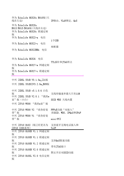
华为 Echolife HG520s B010版(天线在左边)IP路由、VLAN绑定、QoS 华为 Echolife HG520sB013/B015/B016版(天线在右边)华为 Echolife HG520c 联通定制版华为 Echolife HG522-a 电信1个USB华为 Echolife HG522-c 电信相框猫华为 Echolife HG522BBA 电信华为 Echolife HG526 电信TTL插针和JTAG焊点华为 Echolife HG527-a 网通定制版华为 Echolife HG527-c 联通定制版中兴 ZXDSL 531B V3.1.0a_Z21版中兴 ZXDSL 531BIIV3.2.0a_B09版中兴 ZXDSL 531B v5.1.0.6 白色版无线传输速率最大只有11M 中兴 ZXDSL 531B V2.0.1 “我的e家”版(小白)SSID WDS 天线内置中兴 ZXV10 W300 “我的e家”版中兴 ZXV10 W300 V2 “商务@宽带”版PPPoE功能“双接入”多SSID、WDS、IPQoS和UPnP中兴 ZXV10 W300 V1 “商务@宽带”版mini-PCI中兴 ZXV10 H102 (现已经更名为ZXV10 I20X系列)支持蓝牙无绳电话接入和VoIP 中兴 ZXV10 H108B V1.1 网通定制版中兴 ZXV10 H108B V1.1 联通定制版支持QoS限速功能中兴 ZXV10 H108B V1.2 联通定制版带有JTAG接口中兴 ZXV10 H108B V2.0 联通定制版默认开启双SSID功能中兴 ZXV10 H108L V2.0 电信定制版中兴 ZXV10 H608B V1外置天线版电信1个USB中兴 ZXV10 H608B V1内置天线版电信中兴 ZXV10 H608 V2版两个USB接口贝曼元脉 HA710i贝曼元脉 HA910贝曼元脉 HA910_N电信神州数码 DCHG-800-A 电信神州数码 DCHG-800-AI 网通定制版大亚 DB120-WG 我的e家版两个USB接口“双接入”大亚 DB120-WN电信大唐 AS300 HGW-B友讯 D-LINK DSL-2650BU上海贝尔阿尔卡特 RG100A-AA 我的e家版 电信访问控制、固件升级、WDS和修改SN或MAC 有JTAG接口上海贝尔阿尔卡特 RG100A-BA 电信定制版上海贝尔阿尔卡特 RG100A-AA 网通定制版具有SAMBA、脱机FTP下载以及USB 上海贝尔阿尔卡特 RG100A-AA 联通定制版上海贝尔阿尔卡特 RG100S-AA 联通定制版WDSCPU为DA4-9431-PCA (此芯片为华为定制),Switch为ADM6996M,FLASH 4MB,内存为双片共16MB。

AP ® Macroeconomics 2003 Scoring GuidelinesForm BThese materials were produced by Educational Testing Service ® (ETS ®), which develops and administers the examinations of the Advanced Placement Program for the College Board. The College Board and Educational Testing Service (ETS) are dedicated to the principle of equal opportunity, and theirprograms, services, and employment policies are guided by that principle.The College Board is a national nonprofit membership association whose mission is to prepare, inspire, and connect students to college and opportunity. Founded in 1900, the association is composed of more than 4,300 schools, colleges, universities, and other educational organizations. Each year, the College Board serves over three million students and their parents, 22,000 high schools, and 3,500 colleges through major programs and services in college admissions, guidance, assessment, financial aid, enrollment, and teaching and learning. Among its best-known programs are the SAT ®, thePSAT/NMSQT ®, and the Advanced Placement Program ® (AP ®). The College Board is committed to the principles of equity andexcellence, and that commitment is embodied in all of its programs, services, activities, and concerns.For further information, visit Copyright © 2003 College Entrance Examination Board. All rights reserved. College Board, Advanced Placement Program, AP, AP Vertical Teams, APCD, Pacesetter, Pre-AP, SAT, Student Search Service, and the acorn logo are registered trademarks of the College Entrance Examination Board. AP Central is a trademark owned by the College Entrance Examination Board. PSAT/NMSQT is a registered trademark jointly owned by theCollege Entrance Examination Board and the National Merit Scholarship Corporation. Educational Testing Service and ETS are registered trademarks ofEducational Testing Service. Other products and services may be trademarks of their respective owners.For the College Board’s online home for AP professionals, visit AP Central at .The materials included in these files are intended for use by AP teachers for course and exam preparation; permission for any other use must besought from the Advanced Placement Program ®. Teachers may reproduce them, in whole or in part, in limited quantities for noncommercial, face-to-face teaching purposes. This permission does not apply to any third-party copyrights contained herein. This material may not be mass distributed, electronically or otherwise. These materials and any copies made of them may not be resold, and thecopyright notices must be retained as they appear here.Question 1Correct Answers:(a) In the graph above, the economy is currently operating at real output level Y1, which isbelow full-employment output Y f. The price level is P1.(b) With the increase in government spending, AD will shift rightward to AD2 and theequilibrium price level and real GDP will increase to P2 and Y f respectively.Copyright © 2003 by College Entrance Examination Board. All rights reserved.Question 1 (cont’d)(c) The increase in deficit spending and government borrowing will shift the demand curvefor loanable funds to the right, increasing the interest rate as illustrated in the diagram above.(d) Suppose this country is the United States. An increase in interest rates in the UnitedStates will make dollar-denominated financial assets relatively attractive, thus increasing the international demand for the dollar. An increase in international demand for the dollar will cause the dollar to appreciate in value in the international currency market.(e) The appreciation of the domestic currency makes imports relatively inexpensive andexports relatively expensive. Thus, imports will increase and exports will decrease. This will worsen the country’s trade balance.(f) The increase in real interest rates will reduce investment in capital stock, causing long-run growth to decrease.Copyright © 2003 by College Entrance Examination Board. All rights reserved.Question 1 (cont’d)Grading Rubric:Question 1 (15 points):a) 3 points:1 point - Correctly labeled AD/AS graph.1 point - Indication of a capacity constraint, as with a vertical LRAS, a labeledfull employment output level, or a vertical segment of the AS curve.1 point - Current output and price level below full employment.b) 2 points:1 point - Rightward shift in the AD.1 point - Output increases and price level increases.c) 3 points:1 point - Correctly labeled graph.1 point - Right shift in the demand for loanable funds (or left shift in the supply of funds,thinking of it as the private market for loanable funds) and interest rate increase.1 point - Positively sloped loanable funds curve (to accurately reflect interest ratesensitivity).d) 2 points:1 point – Stating that the dollar will appreciate.1 point – For explanation: because dollar denominated financial assets become relativelyattractive, thus increasing the demand for the dollar.e) 3 points:1 point - Imports will increase and exports will decrease.1 point - The appreciating dollar makes imports relatively inexpensive, OR makesexports relatively expensive.1 point - The trade balance will worsen, OR the trade deficit will increase.f) 2 points:1 point - Long-run growth will decline.1 point - Higher real interest rates reduce investment in capital stock, causing growth todecrease.Copyright © 2003 by College Entrance Examination Board. All rights reserved.Question 2Correct Answers:(a) Luna had an absolute advantage in the production of machines because it can producemore machines using the same amount of resources. That is, with the same resources, itcan produce 40 machines while Ashna can only produce 10.(b) Luna had an absolute advantage in the production of food because it can produce moremachines using the same amount of resources. That is, it can produce 40 units of foodwhile Ashna can produce 30 using the same resources.(c) Luna has a comparative advantage in producing machines because it can produce them ata lower opportunity cost than Ashna. Luna forgoes 1 unit of food for each machine,while Ashna forgoes 3 units of food for each machine.(d) Luna should import food because it has a higher opportunity cost of producing food thanAshna. Ashna can produce food at a cost of 1/3 machine per unit of food, while it costsLuna 1 machine per unit of food. Thus, Ashna has a comparative advantage in producing food.(e) If Luna paid ½ machine per unit of food, it would receive food for half the number ofmachines that it must pay without trade, and Ashna would receive ½ machine per unit of food rather than 1/3 of a machine per unit of food as it would receive without trade.Copyright © 2003 by College Entrance Examination Board. All rights reserved.Question 2 (cont’d)Grading Rubric:Question 2: 7 pointsa) 1 point (1/2 for identification and 1/2 for explanation)½ point - Luna has the absolute advantage in machines.½ point - Because it can produce more machines using the same amount of resources.b) 1 point: (1/2 for identification and 1/2 for explanation)½ point - Luna has the absolute advantage in food.½ point - Because it can produce more food using the same amount of resources.c) 2 points:1 point - Luna has a comparative advantage in machines.1 point - Because it has a lower opportunity cost than Ashna.d) 2 point:1 point - Luna will import food.1 point - Because it has a higher opportunity cost of producing food, and Ashna has acomparative advantage in producing food.e) 1 point:Any figure between pre-trade domestic opportunity costs is acceptable. Note thatLuna would pay between 1/3 and 1 machine per unit of food: F = 1/3 to 1 M, andAshna would pay between 1 and 3 units of food per machine: M = 1 to 3 F.Acceptable answers thus include 1M = 1.5 F, 1M = 1.75 F; 1F= 1/2M, etc.Copyright © 2003 by College Entrance Examination Board. All rights reserved.Question 3Correct Answers:(a) The diagram above illustrates the long run and short run Phillips curves for Country X.(b) An increase in government spending will shift the aggregate demand curve to the right,which causes inflation to increase and unemployment to decrease. This corresponds witha movement to the left along a stationary short-run Phillips curve.(c) A drop in inflationary expectations will lead input providers to build smaller increasesinto their wage and rental contracts. The aggregate supply curve will shift to the right as input prices are moderated. The aggregate supply increase will decrease the inflation and unemployment levels for any given level of aggregate demand, and shift the short-runPhillips curve to the left.(d) Increased unemployment insurance benefits will lead unemployed people to invest moretime in the job search process, and more people will be unemployed at any given time.This will increase the natural rate of unemployment and shift the long-run Phillips curve to the right.Copyright © 2003 by College Entrance Examination Board. All rights reserved.Question 3 (cont’d)Grading Rubric:Question 3:10 pointsa) 3 points:1 point - Correctly labeled graph of the Phillips curve (inflation or % change in wage andunemployment)1 point - Short-run Phillips curve (negative slope)1 point - Long-run Phillips curve (vertical)b) 6 points: (3 points for each part)(i) 3 points for effects of government spending:1 point - Inflation up1 point - Unemployment down1 point - No change in Phillips curve, or movement along the curveThese changes result from a rightward shift in AD. However, just an AD/AS graph isinsufficient for any of these points. A clearly labeled Phillips curve can indicate all three elements, as can words.(ii) 3 points for effects of inflationary expectations:1 point - Inflation down1 point - Unemployment down1 point - Phillips curve shifts to the leftA drop in inflationary expectations results in a rightward shift in AS, thus loweringinflation for any given unemployment level and shifting the Phillips curve to the left. Just an AD/AS graph is insufficient.c) 1 point: The Phillips curve shifts to rightWhen unemployment benefits increase, unemployed people invest more time in the jobsearch process, meaning that more people are unemployed at any given time. Thisincreases the natural rate of unemployment and shifts the long-run Phillips curve to the right.Copyright © 2003 by College Entrance Examination Board. All rights reserved.。