N35S-332-BQ0030-KI中文资料
- 格式:pdf
- 大小:219.80 KB
- 文档页数:2


现货供应X射线机XXG-3005D 定向陶瓷管1. 产品介绍XXG-3005D是一款高性能的X射线检测仪器,采用定向陶瓷管发射X射线,具有出色的探测灵敏度和稳定性,广泛应用于医学、工业和安全领域。
2. 主要特点•高性能定向陶瓷管发射X射线,能够快速检测目标物体中的缺陷、异物等。
•大屏幕显示,直观明了,便于操作。
•搭载高度灵敏的便携式探测器,支持手持、固定两种检测方式,适用于不同场合。
•具有多种安全保护设计,包括过压、过流、过载等,保障用户和仪器的安全。
3. 技术规格X射线发射器•发射器类型:定向陶瓷管•发射电压:50-160kV•发射电流:0.1-5mA•定向角度:45度•冷却方式:油冷探测器•探测器类型:高灵敏度探测器•检测方式:手持/固定•探测范围:0.01-9.99μSv/h•探测单元:Si-PIN探测器仪器参数•分辨率:0.1mm•重量:约2.3kg•外形尺寸:210x150x105mm•工作温度:-20℃-50℃•存储温度:-40℃-70℃4. 应用领域医学领域•骨科成像检查:可用于对骨骼系统的病理、畸形进行成像检查,诊断骨折、骨质疏松、关节炎等。
•牙科成像检查:可用于对口腔内的病理、龋齿、残根等进行成像检查,辅助诊断口腔疾病。
工业领域•汽车制造:可用于检测发动机、传动系统、悬挂系统等零部件中的缺陷和损伤。
•金属制造:可用于对钢铁、铝合金、铜等金属制品进行质量检测,其检测效率远高于传统的无损检测方法。
安全领域•边境检查:可用于对行李、车辆、人员等进行安全检查,快速、高效、准确。
•安检:可用于对包裹、快件、邮件等进行X射线照射,发现其中存在的危险品、管制品等。
5. 维护保养•仪器使用后,应将探测器和X射线发射器清洁干净,并妥善保管。
•避免仪器接触水、油和腐蚀性物质,避免磕碰和摔落,保证仪器完好无损。
•定期对仪器进行检查、维护和校准,确保其检测精度和稳定性。
以上就是XXG-3005D定向陶瓷管X射线机的介绍和相关技术规格、应用领域以及维护保养等方面的内容。

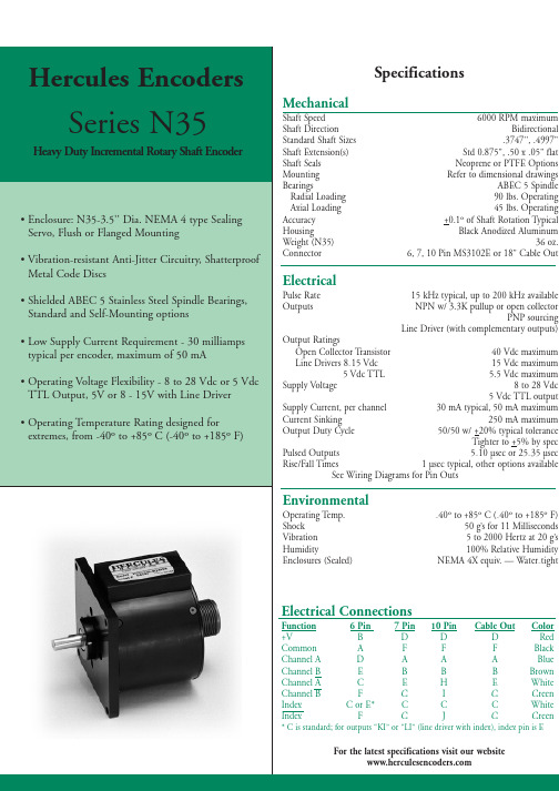
引言尊敬的用户:欢迎使用SW-3000系列红外乳腺检查仪。
“三维”红外乳腺检查仪能得到您的信任,我们深表荣幸。
本说明书的用途在于帮助您正确地使用本产品,内容包括概述、结构特征及工作原理、技术特性、安装说明、使用说明、注意事项、故障分析与排除、保养及维护、售后服务等。
在安装和使用本产品之前,请您务必先仔细阅读随机配送的所有资料,特别是本说明书中安全信息及其他条款所提及的注意事项。
这会有助于您更好地使用本产品。
另外,在使用过程中,如果您有什么问题,请来电、来函查询,或登陆三维网站,我们定当竭诚为您服务。
品牌电脑,打印机等享受全国联保的部分请咨询其免费服务电话,以获得高品质的维护。
免责声明本说明书的描述不代表对本产品规格和软、硬件配置的任何说明。
有关产品规格和配置情况,请查阅本产品的相关协议、装箱单或向产品销售商咨询。
在本说明书编制过程中,已力求内容的正确和完整,但不能保证本手册没有任何错误和疏漏。
徐州市三维医疗设备有限公司坚持不断优化、改善自己的产品和服务,为此保留对本说明书描述的产品及本说明书的内容随时进行修改的权利,恕不另行通知。
如您在使用本说明书过程中发现本产品的实际情况与本说明书有不一致之处,如您想得到最新的信息或有任何问题和想法,欢迎致电我们或登陆三维网站垂询。
有限保证/保修本产品附带了标准服务承诺(保修内容),我们将按照该保修内容为您提供售后服务。
超出本标准的服务承诺,三维公司不提供服务,您应要求向您提供本产品的机构或人员按其承诺为您提供售后服务支持。
在法律允许的最大限度内,在任何情况下徐州市三维医疗设备有限公司无须对下列任何一项负责:1、第三方对您的索赔要求(人身死亡、伤害,不动产和相关有形财产的损害赔偿除外);2、您的记录或数据的丢失或损坏;3、特别的、附带的或间接的损害或任何后果性的经济损失(包括利润和储蓄金的损失),即使徐州市三维医疗设备有限公司已被告知发生上述损失的可能性时,也是如此;4、由于您安装非随本产品提供的软件或硬件产品引起的故障,经判定不是三维产品本身的问题;5、由于您未在本说明书所规定的环境使用本产品,或未按使用说明书所规定的操作方法引起的故障;6、不可抗力因素导致产品损坏的情况。


The SD Series is a range of surge protection devices combining unparalleled packing densities, application versatility, proven reliable hybrid circuitry, simple installation and optional ‘loop disconnect’facilities – features which make the series the ultimate surge protection solution for process equipment, systems I/O and communications networks.The exceptionally high packing densities are the consequence of an ultra slim ‘footprint’ for individual modules which can thus ‘double-up’ as feedback terminals. Each module provides full hybrid surge protection for 2 and 3 wire loop protection.Modules with a comprehensive range of voltage ratings cover all process related signals such as RTDs, THCs, 4 to 20mA loops, telemetry outstations, shut-down systems and fire and gas detectors. Optional ‘loop disconnect’,is a feature which allows commissioning and maintenance to be carried out without removal of the surge protection device.This facility is provided by the SD07, SD16,SD32 and SD55 units. In addition, a thirdconnection on the field and safe side ofthe protector is provided in order toterminate screens safely.For three wire applications the speciallydesigned SD RTD(ResistanceTemperature Detector) and the SD32T3,(for separately powered 4-20mA loops)provide full 3-wire protection in a singlecompact unit. The recommended choicefor the protection of 3-wire pressuretransducers on low power circuits is theSD07R3.For higher bandwidth applications,theSDR series has been developed to meetthe demands of today’s highest speedcommunication systems.120V and 240V AC versionsare available for I/O andpower supplies up tothree Amps of loadcurrent.Telephone networks can be protected bythe SDPSTN.One simple manual operation clampsmodules securely onto DIN rail, whichautomatically provides the essential high-integrity earth connection.‘Top-hat’ (T-section) DIN rail is generallysuitable for mounting SD modulesalthough for adverse environments, aspecially-plated version is available fromMTL Surge Technologies. Acomprehensive range of mounting andearthing accessories can also besupplied, see page 7 for furtherdetails.Ultra-slim user-friendly devices for protecting electronic equipment and systems against surges on signal and I/O cablingSD SeriesO Range of ATEX Certified intrinsically safe surge protectorsO Ultra-slim space-saving design; easy installationO Multistage hybrid protection circuitry – 10kA maximum surge currentO Range of voltage ratings -- to suit all process I/O applicationsO High bandwidth, low resistance, RTD, PSTN and 3-wire transmitter versions availableGuide to applications and selectionAnalogue inputs(high-level)2-wire transmitters, 4-20mA, conventional and smartThe SPDs recommended for use with ‘conventional’and ‘smart’ 4-20mA transmitters(fed by a well-regulated supply) are the SD32 and SD55, the choice depending upon the maximum working voltage of the system (32V and 55V respectively). The diagram illustrates a prime example of an application for which the fuse/disconnect facility is particularly useful, however, both models are available in ‘X’versions without the optional fuse/disconnect feature.Analogue inputs(low-level)RTDsThese applications are best served using the SD RTD. F or optimum accuracy, the energising current should be chosen to ensure the voltage across the RTD does not exceed 1V over the full measurement range. When using a PT100 device, we recommend an energising current of 1mA.ac sensors, photocells, THCs, mV sources and turbine flowmetersThe SD07 or SD16 (depending upon the operational voltage) are the favoured choices for this application. SD07X and SD16X are also suitable.4561232xSD16X, SD32XPIVOVSD16 SD32 SD55SD16X SD32X SD55X (no fuse)456123SDVLogic signalOVSD07 SD16 SD32 SD55SD07X SD16X SD32X SD55X (no fuse)456123LED AlarmSD32X32V maxSD32SD32X(no fuse)IncomingtelephonelineModem,fax ortelephone456123Final output fromPLC,DCS,SCADAetc.110/120V acor220/240V acAnalogue outputsController outputs (I/P converters)F or this application, the recommendations are the SD16, SD32 and SD55 (and the equivalent ‘X’ versions), the final choice depending upon the operating voltage.Digital (on/off) inputsSwitchesSuitable SPDs for switches include the SD07, SD16, SD32 and SD55 modules – the choice depending upon the operating voltage of the system. The ‘X’ versions of these are also suitable. Digital (on/off) outputs Alarms, LEDs, solenoid valves, etcThe recommended choice for this application is the SD32 or SD32X.Telemetry (PSTN)Telemetry outstationsThe SD PSTN has been designed specifically for the protection of signals transmitted on public switched telephone networks.AC supplied equipmentPLC, I/O systemsFor systems on 110-120V ac, the SD150X is the recommended choice and for 220-240V ac systems, the SD275X is recommended.Controller outputs(I/P converters)SwitchesAlarms, LEDs,solenoid valves, etc.Telecom linePLC, I/O systemsFIELD CIRCUIT PROTECTED CIRCUIT32-wire transmitters or sensors4-20mA transmitters, conventional and smartWhere the TP48 is not an acceptable solution, either because of technical suitability or difficulties in mounting, the SD16X, SD32X and SD55X are an excellent alternative.3-wire transmitters or sensorsVibration Sensors and 4-20mA loop processcontrol systems invariably require threewire connections, when powered from anexternal source.This may be accomplished in one unit by usingthe SD32T3 three terminal Surge ProtectionDevice (SPD).Because the SD32T3 protects all threeconductors within the same unit, higherprotection is achieved, as the SPD hybridcircuitry is common to all three wires.The SD07R3 is available for the protection of 3-wire pressure transducers on low powercircuits.4-wire transmitters orsensorsFlow meters, level detectors, etc.4-wire systems such as level detectors requiretwo SDs, one for the supply and the other forthe transmitter output. Generally the voltagesacross the pairs are similar and so therecommended choice would be a pair ofSD16X, SD32X or SD55Xs. However, mainspowered transmitters should be protected withan SD150X or 275X (depending upon supplyvoltage) for the supply inputs.Loadcells are catered for by MTL SurgeTechnologies’ LC30 which is suitable for both 4and 6-wire load cells.series makes it the obvious choice for transmitter protection.The SDs within the junction box should be installed no further than one metre away but as close as possible to the sensor or transmitter they are protecting. A bond is required from the general mass of steelwork to the sensor or transmitter housing either using a flat short braid or a cable of at least 4mm2cross sectional area. In most instances this bond is automatically made by fixing the metallic transmitter housing to the plant structure. This bond ensures the voltage difference between the signal conductors and the transmitter housing is below the transmitter’s insulation rating. Please note that the transmitters or sensors are connected to the ‘Protected Equipment’ terminals of the SD and not the ‘Field Cables’.456123456123456123456123TP48SD32R (no fuse)SD32R (no fuse)SD32R (no fuse)TP48Communication systems protectionHigh speed data links between buildings or one part of a plant to another have become more common with the widespread use of smart transmitters and the increase in unmanned installations. The SD series has an SPD suitable for all process I/O applications with a choice of low resistance units, high bandwidth and a variety of voltage variants. The SDR series has been specially designed to meet the requirements for high speed data links with an extremely high bandwidth.Communication systemsRS232, RS422, RS485The recommended choice for these applications is the SD16R or SD32R depending on the maximum driver signal.Bus powered systemsThere are a variety of bus powered systems specially designed for the process industry. The ideal surge protection device for these systems is the SD32R as it has a very high bandwidth and a modest in-line resistance.Typical ApplicationsTable 1 shows suitable SD devices for different applications. In some applications alternative devices may be used, for example, where lower in-line resistance or a higher voltage power supply is used.Telematic have operationally tested therecommended SD series with representative highways listed but no formal approval for their use in systems by the respective bodies has been sought.RS232, RS422, RS485Bus powered systemsTable 1TP PROTECTED FIELD CIRCUITSD PROTECTED HOST CIRCUITPROTECTED FIELD CIRCUITSD PROTECTED HOST CIRCUITApplicationPreferred SPDAlternativeAllen Bradley Data Highway Plus SD16RFoundation Fieldbus 31.25kbits/s voltage mode SD32R 1.0/2.5 Mbits/s SD55R HART SD32X SD32, SD32R Honeywell DE SD32XSD32, SD32RLonWorks FFT-10SD32R LPT-10SD55R TP-78SD07R IS78†SD32R Modbus ‘& Modbus Plus (RS485)SD16R PROFIBUS DPSD32R PA (IEC 1158, 31.25 kbits/s)SD32R RS232SD16SD16XRS422SD07R RS423SD07R RS485SD07R WorldRP (IEC 1158)SD32R31.25 kbits/s voltage mode 1.0/2.5 Mbits/sSD55RThe SDs should be mounted on the field wiring side to ensure that any surges entering from the field do not damage any intrinsically safe barriers or galvanic isolators in the system. The SDs and IS interfaces should be mounted close to each other but on separate DIN rails in order to maintain the required 50mm clearance between safe area and hazardous area terminals.EarthingThe recommended earthing for field mounted devices has been illustrated previously but it is the earthing at the control panel that is more critical as there are usually a number of earthing systems, each with their own requirements. The earthing system illustrated here replaces the instrument 0V bond, the control system PSU bond and the IS earth with one single earth connection to meet all the design requirements and give the most effective protection against the effects of lightning induced surges.Zone 0 are considered real enough to require preventative measures. IEC 60079-14 (1996-12) Electrical apparatus for explosive gas atmospheres Part 14: Electrical installations in hazardous areas (other than mines) stresses the importance of SPDs in hazardous areas. An outdoor installation where there is a high likelihood of both lightning induced transients and combustible gases requires the installation of SPDs to prevent possible ignition of the gases. Areas seen particularly at risk include flammable liquid storage tanks, effluent treatment plants, distillation columns in petrochemical works and gas pipelines.SPDs for transmitter protection should be installed in Zone 1 but sufficiently close to the Zone 0 boundary to prevent high voltages entering Zone 0. The distance from the SPD to Zone 0 should be less than one metre where possible. However, in practice the SPD would normally be mounted on the transmitter or sensor housing which usually lies in Zone 1and is very close to Zone 0. Because there is only a very small free volume, the SD Series is suitable for mounting in flameproof or explosion proof enclosures.Zone 2The SD series is suitable for protecting electrical circuits in Division 2, Zone 2 and can be used without affecting the safety aspects of the circuit.Non-incendive (low-current) circuits can be protected using any SD series unit mounted in either the safe or hazardous area including those with the fuse disconnect facility. Non arcing (high current) circuits can also be protected except that SPDs with the fuse disconnect facility may only be mounted in the safe area. F or use in these circuits the units must be mounted in a suitable enclosure, normally the minimum requirements are IP54 and 7Nm resistance to impact. The SD series is self certified by Telematic Ltd as being suitable for this purpose.CertificationIntroducing surge protection into Intrinsically Safe (IS) circuits is trouble free as long as the current and power parameters are not exceeded. In the SD Series, the SD**X, SD**R,SD**R3, SD RTD and SD**T3 all have ATEX certification for use in IS circuits located in Zones 0, 1 or 2. The certification parameters for the SD**X and SD**T3 are:EEx ia IIC T4, Li = 0.22mH Ii = 260mA for Ui up to 20V Ii = 175mA for Ui up to 26V Ii = 140mA for Ui up to 28V Ii = 65mA for Ui up to 60VThe certification parameters for the SD**R,SD**R3 and SD RTD are:EEx ia IIC T4, Li = 0Ii = 260mA for Ui up to 60VThe power rating for each of the above is dependent on the table shown below.Pi = 1W (–30°C to +75°C)Pi = 1.2W (–30°C to +60°C) Pi = 1.3W (–30°C to +40°C) The SD** Series are classifed as simple apparatus and are intended for use in Zone 2 or safe areas only, because their fuses are not fully encapsulated.SD Series mounting kits and accessories The SD Series has a full range of mounting kits and accessories to simplify installation and tagging of individual loops. Insulating spacers (ISP7000) are available to allow mounting of the units onto backplanes without compromising correct earthing practice.These are placed at regular intervals along the rail or at each end as required. Earth connections can be made to the DIN rail via the earth terminal (ETL7000). Weatherproof enclosures are also available with all the necessary mounting accessories to install the SD series surge protection devices.Two tagging systems are available. One consists of tagging strips (TAG57) with labels (TGL57) mounted on posts (IMB57) at each end of a row of surge protection devices (SPDs). The other consists of separate tagging identifiers (BRI7000) mounted on the tops of individual SPDs. Both methods can be used conjointly. Replaceable fuses or solid links are available in packs of 5 (SD-F25, SD-F05 and SD-LNK). 7BRI700012BIL7000/BIL7000LSpecification(all figures typical at 25°C unless otherwise stated)Note: all figures are typical at +25°C unless otherwise stated; *standard fuse; +over full working temperature range; †at 20mA with a 250mA standard fuse; ‡these units need external 3A fuses; ^Signal; **Power & Common; maximum energising current depends upon RTD resistance.ProtectionFull hybrid line to lineEach line to screen/groundNominal discharge surge current (I n )10kA (8/20µs),(not applicable to SD150X and SD275X)Nominal discharge surge current (I n )6.5kA (8/20µs),(SD150X and SD275X only)Reaction time (T a )Within nanoseconds (10–9s)RTD resistance range (SD RTD )10 to 1500ΩDegradation accuracy (SD RTD at 1mA)0.1% (RTD resistance >100Ω)0.1Ω(RTD resistance < 100Ω)Ambient temperature–30°C to +75°C (working)–40°C to +80°C (storage)Humidity5 to 95% RH (non-condensing)Terminals2.5mm 2(12 AWG)MountingT-section DIN-rail(35 x 7.5 or 35 x 15mm rail)Weight70g approximately Case flammability UL94 V-2EMC complianceTo Generic Immunity Standards, EN 50082, part 2 for industrial environments R&TTE complianceEN 50082-2 : 1995EN 41003 : 1999EN 60950 : 1992(not applicable to SD150X and SD275X)LVD complianceSD150X & SD275X EN 60950 : 1992EN 61010 : 1995SD PSTNEN 41003 : 1999IEC complianceEN 61643-21:2001To order specify -Order by module, as listed in the specification table and/or accessory part numbers as defined on page 7.Note: In accordance with our policy of continuous improvement,we reserve the right to change the product’s specification without notice.Definitions of terminology used in table 1Working voltage (U n )Maximum voltage between lines or lines/ground for the specified leakage current 2Maximum leakage current (I c )Maximum current drawn by the SPD at the。

最新卓越管理方案您可自由编辑●型号命名电动机的型号由机座号、产品名称代号、性能参数代号等部分组成□ST-□□□派生代号性能参数代号反馈元件代号(M代表代表光电编码器)正弦波驱动电机机座号机座号为:110、130。
反馈元件代号:M—光电脉冲编码器。
性能参数代号:前三位表示额定转矩;后两位表示额定转速;如性能参数代号02030表示额定转矩2N·m,额定转速3000rpm。
派生代号:Z—失电制动器。
110系列130系列额定转矩(N·m) 2 4 5 6 4 5 6 7.710 151500 2500 1500 2500LA 159 189 204 219 166 171 179 192 213 209 241 231 LB 55 55 55 55 57 57 57 57 57 57LC 5 5 5 5 5 5 5 5 5 5LD 12 12 12 12 14 14 14 14 14 14LE 95 95 95 95 110 110 110 110 110 110LF 110 110 110 110 130 130 130 130 130 130 LG 130 130 130 130 145 145 145 145 145 145LZ 9 9 9 9 9 9 9 9 9 9S 19 19 19 19 22 22 22 22 22 22注:抱闸为8N.m;Dc99V。
插座管脚为1,2脚。
LA尺寸:110系列加长74mm。
130系列加长57mm。
●60系列伺服电机参数表●60系列伺服电机安装尺寸:●90系列伺服电机参数表90伺服电机安装尺寸图:●80系列伺服电机参数表80伺服电机安装尺寸图:感谢阅读。

德尔格压缩空气质量检测仪检测管使用说明书汇总Impactor油检测盒使用说明书8103560警告!太高的压力有可能导致破裂或者装置分离。
—只能使用原装德尔格配件(Aerotest)连接impactor 至压力管线。
—只有在测量完成之后移走保护膜—保证彻底将impactor推入(能推多远推多远)适配器并检查是否正确装载—戴上护目镜应用范围用于检测压缩空气中的油雾油蒸汽无法显示需要压缩空气的其它信息:标准测量范围:0.1mg/m3, 0.5mg/m3或者1.0mg/m3检测限:0.05mg/m3油雾周围环境温度:10℃到30℃湿度:最大60%相对湿度压力:只适用于不受力的压缩空气先决条件— Impactor只可与Draeger Aerotest Simultan 联合使用—测量结果只提供所提取用于测量的空气样品中的油雾含量的数据—测量必须由操作的系统进行—取决于表面的吸收和解吸附过程的时间和空间独立的特殊性应当考虑在油雾含量评估中。
完成并评价测量—将德尔格Aerotest压缩空气质量检测仪连接至压缩机,压缩空气气瓶或者长管压缩空气—准备Aerotest用压缩空气冲压缩空气质量检测仪—不带impactor至少3分钟—流速(4L/min)由Aerotest Simultan自动调节—最大程度的将impactor推入Aerotest适配器。
将适配器按照箭头方向插入Aerotest压缩空气质量检测仪—适配器的开口端朝向压缩空气质量检测仪(见图A).观察“Aerotest ”使用说明书。
—进行测量:测量持续时间为5分钟(使用Aerotest 计时表)—移走impactor的保护膜依照图B读取油的浓度9022898_MUL073 2008年3月第二版测量原理压缩空气通过20个小孔引导入impactor垂直至刻花玻璃传感平台。
进入impactor后空气90º改变方向在玻璃界面上根据高度惯性分离空气中的油雾物质。

特点1. 满足RoHS 要求2. 适用于表面安装技术回流焊及波峰焊3. 结构小巧﹑节省空间4. 强大的抑制高浪涌电流能力5. 快速反应的小电感量结构6. 包装材料满足UL94-V07. 工作温度范围:-40 ~ +85°C8. Agency recognition: UL /cUL用途1. 电源供应器2. 家用电器3. 工业设备4. 通信设备5.汽车电子编码规则K R9 10 11 12 13V1mA公差K ±10%包装B 散装R 轴装可选后辍001~ZZZV=18VV=240VV=1000V尺寸&焊盘尺焊盘尺寸寸尺寸(单位﹕mm)尺寸 压敏电压范围 l w h V 1mA =180 ~ 271 3.2+/- 0.3 3225V 1mA =361 ~ 561 8.0+/- 0.36.3+/- 0.34.5+/- 0.3 V 1mA =180 ~ 271 3.2+/- 0.3 4032 V 1mA =361 ~ 75110.2+/- 0.3 8.0+/- 0.34.5+/- 0.3焊盘尺寸(单位﹕ mm)项目A B C L 3225 3.5 2.8 4.5 10.1 尺寸 (EIA)40323.52.86.512.1■电气电气特性特性安规认证压敏电压(@1mADC) 最大连续工作电压最大限制电压(8/20µs)最大冲击电流(8/20µs)最大能量(10/1000µS)额定功率参考电容@1KHzUL cUL型号V1mA (V) V AC(rms)(V)V DC(V)V P(V)I P(A)I max(A)W max(J)P(W)C(pF)UL 1449E173642TVB7S180 18 11 14 36 1.0 150 0.6 0.01 1750 √√TVB7S220 22 14 18 43 1.0 150 0.7 0.01 1450 √√TVB7S270 27 17 22 53 1.0 150 0.9 0.01 1200 √√TVB7S330 33 20 26 65 1.0 150 1.1 0.01 980 √√TVB7S390 39 25 31 77 1.0 150 1.2 0.01 850 √√TVB7S470 47 30 38 93 1.0 150 1.5 0.01 720 √√TVB7S560 56 35 45 110 1.0 150 1.8 0.01 620 √√TVB7S680 68 40 56 135 1.0 150 2.2 0.01 520 √√TVB7S820 82 50 65 135 5.0 400 2.5 0.1 300 √√TVB7S101 100 60 85 165 5.0 400 3.0 0.1 250 √√TVB7S121 120 75 100 200 5.0 400 4.0 0.1 210 √√TVB7S151 150 95 125 250 5.0 400 6.0 0.1 135 √√TVB7S181 180 115 150 300 5.0 400 6.5 0.1 110 √√TVB7S201 205 130 170 340 5.0 400 7.0 0.1 100 √√TVB7S221 220 140 180 360 5.0 400 7.5 0.1 95 √√TVB7S241 240 150 200 395 5.0 400 9.0 0.1 90 √√TVB7S271 270 175 225 455 5.0 400 9.5 0.1 75 √√TVB7S361 360 230 300 595 5.0 400 10.0 0.1 60 √√TVB7S391 390 250 320 650 5.0 400 11.0 0.1 55 √√TVB7S431 430 275 350 710 5.0 400 13.0 0.1 50 √√TVB7S471 470 300 385 775 5.0 400 15.0 0.1 45 √√TVB7S511 510 320 410 845 5.0 400 16.5 0.1 40 √√TVB7S561 560 350 450 930 5.0 400 18.0 0.1 35 √√安规认证压敏电压(@1mADC) 最大连续工作电压最大限制电压(8/20µs)最大冲击电流(8/20µs)最大能量(10/1000µS)额定功率参考电容@1KHzUL cUL型号V1mA (V) V AC(rms)(V)V DC(V)V P(V)I P(A)I max(A)W max(J)P(W)C(pF)UL 1449E173642TVB9S180 18 11 14 36 2.5 300 1.1 0.02 2750 √√TVB9S220 22 14 18 43 2.5 300 1.3 0.02 2300 √√TVB9S270 27 17 22 53 2.5 300 1.6 0.02 1900 √√TVB9S330 33 20 26 65 2.5 300 2.0 0.02 1600 √√TVB9S390 39 25 31 77 2.5 300 2.4 0.02 1400 √√TVB9S470 47 30 38 93 2.5 300 2.8 0.02 1200 √√TVB9S560 56 35 45 110 2.5 300 3.4 0.02 1050 √√TVB9S680 68 40 56 135 2.5 300 4.1 0.02 900 √√TVB9S820 82 50 65 135 10 1200 6.5 0.25 530 √√TVB9S101 100 60 85 165 10 1200 7.0 0.25 480 √√TVB9S121 120 75 100 200 10 1200 9.0 0.25 430 √√TVB9S151 150 95 125 250 10 1200 11.0 0.25 260 √√TVB9S181 180 115 150 300 10 1200 13.0 0.25 220 √√TVB9S201 205 130 170 340 10 1200 15.0 0.25 200 √√TVB9S221 220 140 180 360 10 1200 18.0 0.25 180 √√TVB9S241 240 150 200 395 10 1200 18.5 0.25 170 √√TVB9S271 270 175 225 455 10 1200 21.0 0.25 150 √√TVB9S361 360 230 300 595 10 1200 23.0 0.25 115 √√TVB9S391 390 250 320 650 10 1200 25.0 0.25 105 √√TVB9S431 430 275 350 710 10 1200 29.0 0.25 95 √√TVB9S471 470 300 385 775 10 1200 30.0 0.25 90 √√TVB9S511 510 320 410 845 10 1200 33.0 0.25 85 √√TVB9S561 560 350 450 930 10 1200 33.0 0.25 80 √√TVB9S751 750 460 615 1235 10 1200 50.5 0.25 55 √√■ 功率减额曲线 ■ 冲击电流标准波形最大冲击电流减额曲线LUT=85 环境温度 (℃) 最大额定功率(%)100 电流 (%)时间■最大冲击电流减额曲线最大漏电流与最大限制电压曲线最大漏电流与最大限制电压曲线(TVB 7S 180 ~ TVB 7S 680)推荐焊接条件波峰焊曲线回流焊曲线推荐烙铁重工焊接条件项目条件 烙铁头部温度 360℃ (max.) 焊接时间 3 sec (max.) 烙铁头直径Φ3 mm (max.)温度130±20260℃环境温)/sec℃/sec t■可靠性试验项目测试标准试验条件/ 方法性能要求振荡试验IEC 1051-1 频率范围﹕10 ~ 55 Hz振幅﹕0.75mm 或98 m/s2持续时间﹕6小时(3 x 2小时)无外观损伤∣△V/V1mA∣≦ 5 %可焊性试验IEC 60068-2-20 235±5℃,2±0.5 sec 着锡面积≧95%耐焊接热试验IEC 60068-2-20 260±5℃,10±1 sec无外观损伤∣△V/V1mA∣≦ 5 %高温存储试验IEC 60068-2-2 125±5℃,1000 ±24小时∣△V/V1mA∣≦ 5 %稳态湿热试验IEC 60068-2-3 试验分a、b两组:a. 40±2℃,90 ~ 95 % RH,1344小时b. 40±2℃,90 ~ 95 % RH,10%V DC,1344小时无外观损伤∣△V/V1mA∣≦ 5 %绝缘阻抗≧100MΩ温度急变试验IEC 60068-2-14 温度急变按下表条件循环五个周期。


安装及操作说明名称:透平压缩机系统型号:3(2)VRZ 250/430/16 G序言本安装和操作说明是对3(2)VRZ 250/430/16 G 型透平压缩机开车、操作、维修的重要描述。
因此,在初次开车前,你必须认真阅读安装和操作说明以及LCP的操作手册,已确保安全、经济的使用此透平压缩机。
压缩机的关键部件,例如电机、齿轮单元、油冷器、油过滤器、油泵等也必须遵守此操作说明。
所有的维修活动必须由相关的专家进行。
由于操作疏忽或者维修不当而造成的设备故障,我们将不接受任何质保要求。
我们将为你解决你在此安装和操作说明中遇到的任何问题。
我们希望你们能在不出现任何问题的情况下顺利运行这套系统。
目录表格清单 (6)图纸清单 (6)简介 (7)用途 (7)1.安全规程及说明 (8)1.1安全规程................................................................................. .8 1.2安全说明. (8)1.3重点 (10)2.技术资料 (11)2.1压缩机 (11)2.2与压缩机相连的冷却器............................................................. (16)2.2.1冷却器 (16)2.2.2连接管道 (16)2.2.3冷却器使用的弹簧垫圈........................................................ (16)2.3电机 (16)2.4增速器 (17)2.5联轴器 (17)2.6设备底座 (17)2.7润滑油系统 (18)2.7.1油箱 (18)2.7.2油冷却器 (18)2.7.2.1辅助油泵 (19)2.7.2.2油冷却器 (19)2.7.2.3油过滤器 (19)2.8设备底座、油系统和油冷却器的安装 (20)2.9消耗定额............................................................................. (20)2.9.1润滑油.......................................................................... (20)2.9.1.1过滤油量..................................................................... (20)2.9.1.2润滑油量.................................................. (21)2.9.2密封气.............................................. (22)2.9.3电力消耗....................................................................... (22)2.9.3.1压缩机电机.................................................................. (22)2.9.3.2辅助油泵电机 (22)2.9.3.3油箱加热器 (22)3.压缩机组的各部件名称及功能 (23)3.1压缩机.............................................. . (23)3.1.1压缩机的一般资料 (23)3.1.2设计说明 (27)3.1.2.1转子 (33)3.1.2.2机壳 (33)3.1.2.3导轮和迷宫密封.............................................. . (33)3.1.2.4压缩机转子轴承的安装 (33)3.1.3中冷器和后冷器 (34)3.2驱动系统 (34)3.2.1电机 (34)3.2.2增速器 (34)3.2.3联轴器 (34)3.3润滑油供应 (35)3.4测量和控制技术 (39)3.4.1测量点—密封—连锁........................................................ (39)3.4.2控制点 (39)3.4.2.1进口导叶 (39)3.4.2.2电涌调节 (39)3.4.2.3密封器调节 (40)3.4.3轴振动和径向位移 (40)4.压缩机组的安装 (41)4.1压缩机的安装 (41)4.2辅助单元的安装 (41)4.3铺设油、气、冷却水管线 (41)4.4校正 (42)4.4.1连接加速器和压缩机的联轴器的校正 (42)4.4.2连接电机和加速器的联轴器的校正 (44)5.压缩机装置的试车和操作 (46)5.1初次开车前的准备工作 (46)5.2初始试车 (48)5.2.1机械运转测试 (48)5.2.2操作测试 (48)5.3正常开车 (48)5.4投入氯气开车 (50)5.5停车 (51)5.5.1正常停车 (51)5.5.2故障停车 (52)5.6维护 (53)6.操作故障 (54)6.1主电机 (54)6.1.1主电机不启动 (54)6.1.2主电机停机 (54)6.2加速器 (54)6.2.1油循环温度太高 (54)6.2.2轴承温度太高 (54)6.2.3加速器内突然出现不正常运行噪音 (54)6.3压缩机 (55)6.3.1运行不稳定 (55)6.3.2所有轴承温度升高 (55)6.3.3某一个轴承温度升高 (55)6.3.4压缩机出口气体温度升高 (55)6.3.5密封气压力降低 (55)6.4润滑油系统 (55)6.4.1过滤器出口油压降低 (55)6.4.2冷却器出口油温太高 (55)7.预防性的维修、拆卸和安装 (56)7.1压缩机 (56)7.2检查 (61)7.3联轴器 (62)7.4冷却器 (62)7.5主电机 (62)7.6增速器 (62)7.7油冷却器 (62)7.8油过滤器 (62)7.9油泵 (62)7.10油箱 (63)7.11附录:安装和拆卸斜垫轴承的说明书 (63)8.运输 (70)9.备用和防护部件 (73)9.1防护部件 (73)9.1.1压缩机 (73)9.1.2增速器 (73)9.2备用配件 (73)9.2.1压缩机 (73)9.2.2增速器 (74)9.2.3联轴器 (74)9.2.4油冷却器 (74)9.2.5油过滤器 (74)9.2.6连接管线 (74)9.3安装和控制设备 (74)10.版权 (75)表格清单表 1.压缩机单元部件清单 (24)表 2.压缩机单元部件清单 (28)表 3.进口可调导叶设备清单 (30)表 4.油系统设备清单 (36)图纸清单图 1.压缩机工作特征图 (15)图 2.压缩机单元 (25)图 3.压缩机单元 (26)图4压缩机剖视图 (29)图5入口可调导叶 (31)图 6.入口可调导叶 (32)图7.油系统 (37)图8.油系统 (38)图9.增速器和压缩机之间的连接 (44)图10.电机和增速器之间的连接设备 (45)图11.方框图 (49)图12.松开连接杆 (56)图13.压缩机控制点 (59)图14.压缩机控制点 (60)图15.径向轴泵倾斜垫的安装位置 (64)图16.倾斜垫的拆卸 (66)图17.止推轴承 (67)图18.止推轴承结构图 (68)图19.止推轴承热探测器 (69)图20.止推轴承热探测器 (69)图21.压缩机系统运输说明 (70)图22.压缩机运输说明 (71)图23.油系统运输说明 (72)简介此压缩机单元包括1个带有中冷器的二级离心式压缩机、1个透平增速齿轮系统、一个电动机、一个压缩机底座、一个增速器单元和电机、两个中冷却器及连接管道、一个润滑油系统、一个密封气系统以及必要的检测和控制技术。
