LM215WF3-SDC2_CAS_K60 ver1[1].0_13th Jan_2011(Apple)
- 格式:pdf
- 大小:920.24 KB
- 文档页数:35
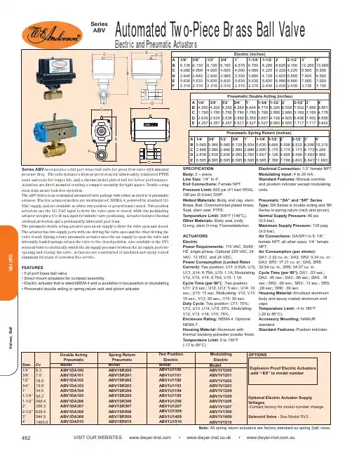
VISIT OUR WEBSITES: • • .auElectric and Pneumatic ActuatorsSeries ABV incorporates a full port brass ball valve for great flow rates with minimal pressure drop. The valve features a blowout proof stem for added safety, reinforced PTFE seats and seals for longer life, and a chrome/nickel plated ball for better performance.Actuators are direct mounted creating a compact assembly for tight spaces. Double o-ring stem seals assure leak free operation.The ABV Series is an economical automated valve package with either an electric or pneumatic actuator. Electric actuated models are weatherproof, NEMA 4, powered by standard 115VAC supply, and are available in either two-position or proportional control. Two-position actuators use the 115 VAC input to drive the valve open or closed, while the modulating actuator accepts a 4 to 20 mA input for infinite valve positioning. Actuator features thermal overload protection and a permanently lubricated gear train.The pneumatic double acting actuator uses an air supply to drive the valve open and closed.The actuator has two supply ports with one driving the valve open and the other driving the valve closed. Spring return pneumatic actuator uses the air supply to open the valve and internally loaded springs return the valve to the closed position. Also available is the SV3solenoid valve to electrically switch the air supply pressure between the air supply ports for opening and closing the valve. Actuators are constructed of anodized and epoxy coated aluminum for years of corrosion free service.FEATURES• Full port brass ball valve• Direct mount actuators for compact assembly• Electric actuator that is rated NEMA 4 and is available in two position or modulating • Pneumatic double acting or spring return rack and pinion actuatorCBA DEFSPECIFICATION Body:2 – piece.Line Size:1/4˝ to 4˝.End Connections:Female NPT.Pressure Limit:600 psi (41 bar) WOG,100 psi (6.9 bar) SWP .Wetted Materials:Body, end cap, stem:Brass; Ball: Chrome/nickel plated brass;Seat, stem seal: PTFE.Temperature Limit:300°F (148°C).Other Materials:Body seal, body O-ring, stem O-ring: Fluoroelastomer. ACTUATORS ElectricPower Requirements:115 VAC, 50/60HZ, single phase. Optional 220 VAC, 24VAC, 12 VDC, and 24 VDC.Power Consumption (Locked Rotor Current):Two position: U11: 0.55A; U12,U13, U14: 0.75A; U15: 1.1A; Modulating:V12, V13, V14: 0.75A; V15: 1.1A. Cycle Time (per 90°):Two position: U11: 2.5 sec.; U12, U13: 5 sec.; U14: 10sec.; U15: 15 sec. Modulating: V12, V13:10 sec.; V13: 20 sec.; V15: 30 sec.Duty Cycle:Two position: U11: 75%;U12, U13, U14, U15: 25%. Modulating:V12, V13, V14, V15: 75%.Enclosure Rating:NEMA 4. Optional NEMA 7.Housing Material:Aluminum withthermal bonding polyester powder finish.Temperature Limit:0 to 150°F (-17 to 65°C).Electrical Connection:1/2˝ female NPT.Modulating Input:4 to 20 mA.Standard Features:Manual override and position indicator except modulating units.Pneumatic “DA” and “SR” SeriesType:DA Series is double acting and SR Series is spring return (rack and pinion).Normal Supply Pressure:80 psi (5.5 bar).Maximum Supply Pressure:130 psig (9.0 bar).Air Connections:DA/SR1 to 5: 1/8˝female NPT, all other sizes: 1/4˝ female NPT.Air Consumption (per stroke):DA1: 2.32 cu. in.; DA2, SR2: 9.34 cu. in.;DA3, SR3: 17.21 cu. in.; DA5, SR5:39.54 cu. in.; SR6: 54.37 cu. in.Cycle Time (per 90°):DA1: .03 sec.;DA2: .05 sec.; DA3: .06 sec.; DA5: .18sec.; SR2: .09 sec.; SR3: .13 sec.; SR5:.28 sec.; SR6: .39 sec.Housing Material:Anodized aluminum body and epoxy coated aluminum end caps.Temperature Limit:-4 to 180°F (-20 to 85°C).Accessory Mounting:NAMUR standard.Standard Features: Position indicator.E CBADNote: All spring return actuators are factory standard as spring (fail) close.。
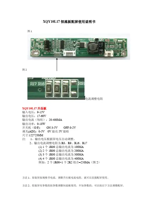
XQY10L17恒流板配屏使用说明书图1图2电流调整电阻XQY10L17升压板输入电压:9-15V输出电压:17-60V输出电流(每组):20-400MA输出功率:0-18W开关机(O/F):ON:3-5V OFF:0-2V调光(ADJ):0-5V0V最亮5V最暗尺寸:122*23MM注:1、输出电压根据屏电压自动调整。
2、输出电流调整电阻为R8、R9、R16、R17(1)1个1R00总输出电流为100MA(2)2个1R00总输出电流为200MA(3)3个1R00总输出电流为300MA(4)4个1R00总输出电流为400MA例如:2个1R00+1个2R2组合=250MA(图2)方法1、原装屏按规格书电流,调整升压板电流电阻,就可以直接配屏使用。
方法2、组装屏有参数的按参数调整恒流板使用,不知参数的,可以按以下方法调整配屏。
第一步,先用200MA的恒流板点亮屏,测试下恒流板供给屏的电压在17-40V的可配250MA恒流板,电压在40-60V的可配200MA恒流板。
(适用于18.5-23.6寸)。
第二步,配好后点亮1小时,用手摸下屏边灯条座置,确认温度,40-55度(能长期手摸为配屏正确,不能长期手摸的说明末配好屏,可以调小电流,再次重配。
方法3、组装屏不知参数的,可计算电流配屏。
18.5寸19寸宽屏正屏功率为7--10W21.5寸宽屏正屏功率为10---13W23.6寸宽屏正屏功率为13---15W功率W除以所测到电压V=电流A,就可调整恒流板配屏。
以上3个方法配好屏,都要经过方法2第二步温度确认为准。
以上配屏资料是按常规组装屏经验所得。
本文只供参考。
如有疑问请电话联系莫工:135********QQ:59938492适用屏如下:群创:MT185GW01V.1、MT185GW01V.3、MT185GW01V.4、MT190AW02V.3、MT190AW02V.4、MT190AW02V.W、MT190EN02V.W、MT200LW02V.0、MT200LW01V.1、MT215DW02V.0、MT215DW01V.1、MT215DW01V.3、MT220WW01V.T、MT220WW01V.7、MT230DW01V.1、MT230DW01V.2、MT230DW01V.3、MT230DW03V.0、MT230DW03V.1中华:CLAA185WA04、CLAA215FA04、CLAA215FA04V2、CLAA215FA04V4、CLAA215FS05、CLAA220UA01、CLAA220UA01A奇美:M185BGE-L21、M185BGE-L23、M185BGE-L22、M185B3-LC1、M185BGE-L10、M185B3-LA1、M185B3-L01、M185B3-L03、M190E6-L0E、M190E6-L01、M190CGE-L20、M190Z3-L06、M190Z3-L01、M190Z3-L02、M190Z3-L05、M200FGJ-L2U、M200FGE-L23、M200FGE-L1A、M200O3-LA3、M200FGE-L20、M200O3-LA1、M200O3-L01、M215HGJ-L2U、M215HGG-L10、M215HGE-L23、M215HGE-L21、M215HGJ-L21、M215H3-L03、M215H3-LA5、M215HGE-L1A、M215HGE-L10、M215H3-LA1、M215H3-L01、M220Z2-L02、M220J3-L01、M220Z3-L01、M220Z3-LA3、M220ZGE-L20、M220Z3-LA1、M220Z3-L07、M220Z3-L03、M220Z2-L01、M230HGE-L20、M236HGJ-L1U、M236HGE-L23、M236HGE-L20、M236HGJ-L11、M236HGE-L10、M236H3-LA3、M236H5-LA3、M236H3-L05、M236H3-LA2、M236H3-L02、M236H3-L01、M236HHF-L11、M236H5-L0A、M270HGE-L20、M270HGE-L10、M270H5-LA2、M270H3-L03、M270HHF-L10、M270H3-L01、、V185BG2-LE1、V185B1-LE2、V185B1-LE1、V215H1-LE1、V215H1-LE2、V236H1-LE6、V236H4-LE1、V236H3-LH3、V236H1-LE4、V236H1-LE3、V236H1-LE1、V236H3-LS1、V236H1-LE2、V236H1-DE01、TT260GW01V.0、V260B3-LE1、V260B3-LE2、V260H1-LE1、V260H1-LE2、V260B2-LE1、V260B2-DE03友达(AUO):M185XTN01.0、M185XW01VG、M185XW01VF、M185XW01VD、M185XW01 VE、M185XW01V3、M185HW01V6、M185HW01VD、M185XW01V6、M185XW01V7、M190EG02V9、M190PW01V8、M200RW01V6、M201UN02V0、M201SP01V2、M201EW02 VE、M215HW03V1、M215HW02V0、M215HW01VE、M215HW01VB、M215HW01V8、M215HW01V6、M230UW01V0、M240HW01VD、M240HW02V6、M240HW02V1、M240HW01VB、M240HW01V9、M240HW01V6、M240HW01V1、M270HW01V2、M270HW02V3、M270HW02V2、M270HW02V1、M270HW02V0、、T240XVN01.0、T240HW01V0、T260XVN01.4、T260XW06V4、T260XW06V5、T260XW06V1、T260XW06 V2、T260XW06V0、T260XW05V5、京东方(BOE):HM185WX1-400、HM185XW1-400、HM215WU1-500、HT185WX1-300、HT215F01-100、HT260WXC-200、LG:LM185WH2-TLA3、LM185WH2-TLC1、LM185WH2-TLA1、LM190E09-TLB2、LM190E09-TLC1、LM190E09-TLA1、LM190E09-TLB1、LM200WD3-TLC7、LM200WD3-TLA4、LM200WD4-SLB1、LM200WD3-TLC1、LM200WD3-TLA5、LM200WD3-TLA3、LM200WD3-TLA2、LM200WD3-TLA1、LM215WF8-TLA1、LM215WF5-SLA1、LM215WF3-SLC5、LM215WF3-SLC2、LM215WF4-TLA2、LM215WF3-SDC2、LM215WF3-SDB1、LM215WF4-TLE1、LM215WF4-TLE7、LM215WF3-SLC1、LM215WF4-TLA4、LM215WF4-TLA3、LM215WF4-TLA1、LM215WF3-SLA1、LM215WF3-SDA1、LM220WE5-TLC1、LM220WE5-TLA2、LM220WE5-TLA1、LM230WF3-SLD1、LM230WF5-TLB1、LM230WF8-TLA3、LM230WF3-SLB2、LM230WF5-TLD5、LM230WF5-TLD2、LM230WF5-TLD1、LM230WF5-TLC2、LM230WF5-TLC1、LM230WF5-TLA2、LM230WF5-TLA3、LM230WF8-TLA1、LM230WF6-SLA1、LM230WF3-SLB1、LM230WF5-TLA1、LM240WU8-SLA1、LM240WU8-SLA2、LM240WU6-SDA1、LM240WU5-SLA1、LM270WF5-SLB1、LM270WQ1-SDE3、LM270WQ1-SLA1、LM270WF3-TLA1、LM270WQ1-SDC2、LM270WF2-TLA5、LM270WF2-TLA1、LM270WQ1-SDA2、三星:LTM185AT05、LTM185AT04、LTM185AT04-V、LTM190BT08、LTM200KT10、LTM200KT08-W02、LTM200KT08-V、LTM200KT07、LTM200KT05、LTM215HT04、LTM215HT03、LTM220MT04、LTM220MT09、LTM230HL01、LTM230HT10、LTM230HT09、LTM230HT05、LTM230HT04、LTM240CL01、LTM240CT06、LTM240CS02、LTM270HT03、LTM270DL02、龙腾:M190MWW4R2、M236MWF2R0、M236MWF1R116L0354、组装屏:M190ID1WW3-1、T260B2-P03-L01、天马:TM190MDS01、TM240320A7NFWVGWC2-1、TM240320LNFWUG、TM240320INFWG1、TM240320C1NFWGWC、TM240320B9NFWUGWC、TM240320B8NFWGWC、夏普:LQ185K1LGN3、LQ185K1LGN1、LQ185T1LGN3、LQ185T1LGN2、LQ190E1LW52、LQ190E1LX51、LQ190E1LW51、LQ215M1LGN2、LQ215M1LXXX、LQ220AC9001、LQ230M1LW1110PM156B3-L01V260H1-LE2、V260H1-LE312PV260B3-LE1、V260H1-LE1、M236H3-L01、M185B3-L01LM215WF4-TLA1LM215WF4-TLA3LTM200KT08W01LTM200KT10LG236LM230WF5-TLA1LM200WD3-TLCCLM215WF4-TLE1LM215WF3-SLC5LM215WF4-TLE8LM185WH2-TLC1LM215WF4-TLE2LM215WF4-TLE7LM215WF4-TLE9M230WA01-EDLM220WE5-TLC1CLAA185WA04MT190AW02V.4 LM185WH2-TLA1 MT185GW01V.4 MT215DW02-V.0 TPM190A1-LOGM185XW01V7 CLAA215FA04 CLAA185WA04 CLAA215WA04-K CLAA185WA04-KMT190AW02-V.W MT200LW02V.0 M200FGE-L1ALM220WE5-TLA1 M185XW01-V6M215H3-LA1M215H3-LA5M185B3-LA1V216B1-LE1M22023-LA1LM220WE5-TLA1M236H3-LA2V236H1-LE2 HCGD19V236CDH11-2M236IDEWF1LTM170ET01A150XN01A150X1V01V2 PV200WLEDM-P21HM230WA01-ED TPM190A1-MWW3MTPV190WLEDM-V53H M215HW01V7TM104SDH01V1.0 LTM190BT08、TPM190A1-MWW3PV220WLEDM-P21H LTM185AT04M190MWW4AU M185XW01-VDM215HGE-L10AU M215HW01-VB LTM215HT03MT215DW01-V.1MT215DW01-V.3MT215DW01-V.2LQ215M1LGN2LQ215M1LXXXMT230DW01M215HW01-V6MT185GW01-V.1MT185GW01V0MT185GW01V2MT185GW01V3LQ185K1LXXXLQ185T1GN3M236H3-L01M185B3-L01M156B3-L01V260H1-LE1V260H1-LE3M240HW02V.1V216H1-LE1V215H1-LE1V215H3-LA1V236H1-L01M240HW01VBM240HW01V6LM230WF3-SLC1LM230WF5-TLA(C)1M215HGJ-L22M215HW01V6TPT260B2-TWR1M236MWF2M215HGE-L1AM215FGE-L1ALM230WF5-TLD1LM230WF5-TLA3M215HW03V.1M185BGE-L10AU M190PW01V8M215H1-P01-LE2M215HGJ-L21LM200WD3-TLC7(9) LTM270HT03M215HW02V.0LM230WF8-TLA1LM230WF5-TLF1LM230WF3-SLC1 LTM230HT10M236HGE-L10M236HGE-L20M230HGE-L20MT230DW03V.0M240HW01V1M236H1-P01M200TGE-L20M200O3-LA3M200O1-L07M200O1-L02LM215WF3-SLC5M190Z3-L06LTM200KT08-W01V260H1-LE2V260B3-LE1M185XW01V.3LM185EXNM200FGJ-L20REV.C1 LQ215M1LGN2LM270WF4-TLA1LM270WF6-SLC1CL2160000V236H1-LE4T260XW06V5M156B3-L01HT215F01-100M190CGE-L20LM200WD4-SLB2 LM200WD3-TLF1 LM215WF3-SLE1 LM230WF5-TLF1 LM230WF5-TLF2 LM230WF5-TLD1 LM230WF3-SSA1 LM270WF6-SSZ1 LM270WF6-SLZ1AUO A150XN01V.2M156BGE-L10M156BGE-L01M200FGE-L23T240XVN01.0HT185WX1-100LM215WF7-SLB1。
沃伦森电气(WARENSEN)多年来一直专注于输配电系统无功补偿、滤波及电力电子设备的研发、生产和工程实施。
公司引入德国先进制造工艺和技术,坚持“积木式设计理念模块化成套产品”的产品战略,全心全意打造行业最具价值品牌!公司所生产的:WUAPF、WRS-APF、WMPF-12系列有源滤波装置主要应用于谐波污染严重的工况下;WRS-IC(R)、WRS-CRT(S)、WMT(S)C、WMXC-12、WMC-12、WMC-35系列无功补偿装置主要应用于电网等无功负荷波动较小的工况下;WRS-SVG、WDSVG、WIDSVG、WMSVC、WTSVC主要应用于无功负荷波动剧烈、电压闪变严重的工况下。
以上系列产品均可针对单独工程具体设计并提供项目策划书。
公司坚持“产品如人品质量是生命”的质量理念,保证产品卓越品质,并把“完美的产品是艺术品”作为产品制造工艺的唯一准则。
沃伦森电气(WARENSEN)在引入德国技术发展的同时,更注重人才与自主技术的储备,坚持与科研院所合作,定向培训、学术交流,联合建立研发基地,不断进行技术创新,提高产品先进性,保持行业领先水平。
一流的团队,一流的质量,一流的服务是我们的动力和源泉。
沃伦森电气(WARENSEN)不仅要做一个制造高品质产品的生产商,还要做一个用户满意,高效反应机制,不断创新的服务提供商。
互惠互利,与用户共赢,是我们永远的追求和目标。
电容器+电抗器WRS-CR7-10/400V WRS-MKP10/400-3 WRS-CK-10/400-3WRS-CR7-15/400V WRS-MKP15/400-3 WRS-CK-15/400-3WRS-CR7-20/400V WRS-MKP20/400-3 WRS-CK-20/400-3WRS-CR7-25/400V WRS-MKP25/400-3 WRS-CK-25/400-3WRS-CR7-30/400V WRS-MKP30/400-3 WRS-CK-30/400-3WRS-CR7-40/400V WRS-MKP40/400-3 WRS-CK-40/400-3WRS-CR14-10/400V WRS-MKP10/400-3 WRS-CK-10/400-3WRS-CR14-15/400V WRS-MKP15/400-3 WRS-CK-15/400-3WRS-CR14-20/400V WRS-MKP20/400-3 WRS-CK-20/400-3WRS-CR14-25/400V WRS-MKP25/400-3 WRS-CK-25/400-3WRS-CR14-30/400V WRS-MKP30/400-3 WRS-CK-30/400-3WRS-CR14-40/400V WRS-MKP40/400-3 WRS-CK-40/400-3电容电抗模块产品(晶闸管)WRS-CRT7-30/2-400VWRS-CRT7-30/2-400VWRS-CRT7-30/1-400VWRS-CRT7-30/2-400VWRS-CRT7-60/2-400VWRS-CRT7-60/2-400VWRS-CRT7-60/1-400VWRS-CRT7-60/2-400VWRS-CRT7-60/1-400VWRS-CRT7-60/2-400VWRS-CRT7-90/1-400VWRS-CRT7-60/1-400VWRS-CRT7-90/1-400VWRS-CRT7-60/2-400VWRS-CRT7-60/1-400VWRS-CRT7-90/1-400VWRS-CRT7-60/1-400VWRS-CRT7-90/1-400VWRS-CRT7-60/1-400VWRS-CRT7-90/1-400VWRS-CRT7-90/1-400VWRS-CRT14-30/2-400VWRS-CRT14-30/2-400VWRS-CRT14-30/1-400VWRS-CRT14-30/2-400VWRS-CRT14-60/2-400VWRS-CRT14-60/2-400VWRS-CRT14-60/1-400VWRS-CRT14-60/2-400VWRS-CRT14-60/1-400VWRS-CRT14-60/2-400VWRS-CRT14-90/1-400VWRS-CRT14-60/2-400VWRS-CRT14-60/1-400VWRS-CRT14-90/1-400VWRS-CRT14-60/2-400VWRS-CRT14-60/1-400VWRS-CRT14-90/1-400VWRS-CRT14-60/1-400VWRS-CRT14-90/1-400VWRS-CRT14-60/1-400VWRS-CRT14-90/1-400VWRS-CRT14-90/1-400V电容电抗模块产品(接触器)WRS-CRS7-30/2-400VWRS-CRS7-30/2-400VWRS-CRS7-30/1-400VWRS-CRS7-30/2-400VWRS-CRS7-60/2-400VWRS-CRS7-60/2-400VWRS-CRS7-60/1-400VWRS-CRS7-60/2-400VWRS-CRS7-60/1-400VWRS-CRS7-60/2-400VWRS-CRS7-60/2-400V WRS-CRS7-60/1-400V WRS-CRS7-90/1-400V WRS-CRS7-60/2-400V WRS-CRS7-60/1-400V WRS-CRS7-90/1-400V WRS-CRS7-60/1-400V WRS-CRS7-90/1-400V WRS-CRS7-60/1-400V WRS-CRS7-90/1-400V WRS-CRS7-90/1-400V WRS-CRS7-400V WRS-CRS14-30/2-400V WRS-CRS14-30/2-400V WRS-CRS14-30/1-400V WRS-CRS14-30/2-400V WRS-CRS14-60/2-400V WRS-CRS14-60/2-400V WRS-CRS14-60/1-400V WRS-CRS14-60/2-400V WRS-CRS14-60/1-400V WRS-CRS14-60/2-400V WRS-CRS14-90/1-400V WRS-CRS14-60/2-400V WRS-CRS14-60/1-400V WRS-CRS14-90/1-400V WRS-CRS14-60/2-400V WRS-CRS14-60/1-400V WRS-CRS14-90/1-400V WRS-CRS14-60/1-400V WRS-CRS14-90/1-400V WRS-CRS14-60/1-400V WRS-CRS14-90/1-400V WRS-CRS14-90/1-400V 智能电容器WRS-IC-450/10WRS-IC-450/15WRS-IC-450/20WRS-IC-450/25WRS-IC-450/30WRS-IC-450/40WRS-IC-450/50WRS-IC-450/60WRS-IC-450/70智能电容器(电抗器)WRS-ICR7-480/10WRS-ICR7-480/15WRS-ICR7-480/20WRS-ICR7-480/24WRS-ICR7-480/30WRS-ICR7-480/35WRS-ICR7-480/40WRS-ICR7-480/45WRS-APF模块产品WRS-APF25/400VWRS-APF35/400VWRS-APF50/400VWRS-APF60/400VWRS-APF75/400VWRS-APF100/400VWRS-SVG模块产品WRS-SVG50/400VWRS-SVG100/400V静止无功发生器WRS-SVG WDSVG-12/1000-N WDSVG-12/2000-N磁控式动态补偿滤波装置WMSVC-12/600-600-N WMSVC-12/1000-1000-N WMSVC-12/1200-1200-N WMSVC-12/600-600-W WMSVC-12/1000-1000-W WMSVC-12/1200-1200-W 高压无功补偿装置WMC-12/1000-3NWMC-12/1200-4NWMC-12/1600-4NWMC-12/2000-5NWMC-12/1000-3WWMC-12/1200-4WWMC-12/1600-4WWMC-12/2000-5W高压线路装置WMXC-6/50+100JWMXC-6/100+100J WMXC-6/200+100J WMXC-6/100+200JWMXC-6/100+100 WMXC-12/50+100J WMXC-12/100+100J WMXC-12/200+100J WMXC-12/100+200J WMXC-12/100+100低压有源滤波装置WUAPF-480/50-2N WUAPF-480/75-2N WUAPF-480/100-3N WUAPF-480/125-3N WUAPF-480/150-3N WUAPF-480/200-4N低压无功补偿装置WMTC-400/90-4N WMTC-400/120-3N WMTC-400/180-4N WMTC-400/240-4N WMTC-400/300-5N WMTC-400/360-6N WMTC-400/480-6N低压无源滤波装置WTSF400-100/3-N WTSF400-200/4-N WTSF400-300/5-N低压控制器WRS-DK-12TWRS-DK-21TWRS-DK-12SWRS-DK-21S高压控制器WRS-HK-700智能电容器控制器WRS-IK-200电容器综合保护单元WRS-HB-1000电能质量在线监测装置WRS-600S动态补偿调节开关WRS-TD1永磁式电容投切真空开关WRS-ZNT12/630-Y。

SE2-hAND SERIESThe SAFeasy TM light curtains, according to the Iec 61496-1 e Iec 61496-2 standards, are suitable for hand protection of operators exposed to risks.Different models with eleven standard heights ranging from 150 to 1650 mm, 35 mm resolution and an operating distance reaching 15 m are available. specific dip-switches, that can be reached through a slot present on the front of the receiver protected by a lid and opened with a simple screwdriver, guarantee rapid and safe device setting. the operator is thus able to configure, according to the specific needs, the manual or automatic restart, as well as the muting and partial muting functions. the emitter-receiver units are optically synchronised and contain all the control circuits, inputs and outputs inside the housing.The SAFeasy TM light curtains have also integrated the test function, automatically activated every second, without stopping the machine’s working cycle.a wide range of industrial applications, requiring operator safety, can be solved by the SAFeasy TM light curtains, thanks to the extremely compact dimensions (35x40 mm) and easy connection and installation.SAFeTY LIGHT CURTAINSHAND PROTeCTIONSAFeTYPower supply: 24 vdc ± 20% (seLv/PeLv)Consumption:70 ma max. / 2.1 w (emitter)100 ma max. / 3 w (receiver without load)Light emission: infrared Led 880 nmOptic diameter:Ø 16 mm Number of controlled beams:refer to table 1Optic interaxis: refer to table 2Resolution:refer to table 21st beam installation height: refer to table 3Through beam operating distance:0.5 ... 25 m (Q vers.)4 ... 50 m (P vers.)Receiver inputs:external switches for muting, test, restart andoverrideReceiver indicators:green / red safe / break Led2 yellow aLIgnment Ledsgreen Power on Led emitter indicators:yellow blinking faILure Led green Power on Led Output type: 2 PnP Output current:0.7 a max.0.25 a max. (45°c - 55°c)short-circuit signalling and protectionResponse time:14 msSelectable functions:total / partial muting manual / automatic restartrefer to table 4Time-out period:muting: 10 minutes override: 2 minutesMuting signalling lamp:24 v3 w min. (125 ma), 7 w max. (300 ma)Receiver connection: 8-pole m12 connector emitter connection:4-pole m12 connectorCable length: 50 m max. (with 50 nf capacitive load)Safety category:type 4electrical protection: class 1Mechanical protection: IP65IP67 (connector part)Housing material:aluminium with Pc makrolon plastic capsWeight:1.2 kg max. / m of total heightOperating temperature: -10 ... +55 °c Storage temperature:-25 ... +70 °cReference standards:en 954-1, Iec 61496-1, Iec 61496-2Table 4: DIP-SWITCh SELECTIONTable 1: NUMBER OF BEAMSTable 2: CONTROLLED hEIGhT (mm)Table 3: RESPONSE TIME (ms)GReY dip-switches: total / partial muting selection WHITedip-switches: manual / auto. restart selectionDIMeNSIONSRX: M12 8-POLE CONNECTORTX: M12 4-POLE CONNECTORversIons L 1 L 2 se2-35-015-PP-w 256147se2-35-030-PP-w 403294se2-35-045-PP-w 550441PL (ref. en Iso 13849-1)d cat (ref. en 954-1)2sIL (ref. en Iec 61508)2sIL cL (ref. en Iec 62061)2Pfhd – Probability of danger failure (1/h)1,37e-08t1 – Life time (years)20mttfd - mean time to danger failure (years)309dc – diagnostic coverage (%)96,3%sff – safe failure fraction (%)97,83%hft – hardware fault tolerancencthe company endeavours to continuously improve and renew its products; for this reason the technical data and contents of this catalogue may undergo variations without prior notice. for correct installation and use, the company can guarantee only the data indicated in the instruction manual supplied with the products.ACCeSSORY SeLeCTION AND ORDeR INFORMATIONPlease refer also to Safety Device Accessories。

FAQ 04/2016Working with the 3SK2 diagnostic displayEasy diagnosis and transferring of safety programS i e m e n s A G 2016 A l l r i g h t s r e s e r v e dThis entry is from the Siemens Industry Online Support. The general terms of use (/terms_of_use ) apply.Security informa-tionSiemens provides products and solutions with industrial security functions that support the secure operation of plants, solutions, machines, equipment and/or networks. They are important components in a holistic industrial securityconcept. With this in mind, Siemens’ products and solutions undergo continuous development. Siemens recommends strongly that you regularly check for product updates.For the secure operation of Siemens products and solutions, it is necessary to take suitable preventive action (e.g. cell protection concept) and integrate each component into a holistic, state-of-the-art industrial security concept. Third-party products that may be in use should also be considered. For more information about industrial security, visit /industrialsecurity . To stay informed about product updates as they occur, sign up for a product-specific newsletter. For more information, visit .Table of contents1 Product overview ............................................................................................... 5 2Controlling and monitoring .............................................................................. 6 2.1 Preparation in the software .................................................................. 8 2.1.1 Filling in of project information ............................................................. 8 2.1.2 Preparation for detailed status information ........................................ 10 2.2 Displaying of plant information ........................................................... 11 2.2.1 Reading out of project information ..................................................... 11 2.2.2 Reading out of status information ...................................................... 12 2.3 Fault diagnostic .................................................................................. 14 3Transferring of projects by the help of the diagnostic display (15)3.1 Preconditions ...................................................................................... 15 3.2 Procedure ........................................................................................... 17 3.3 Use cases ........................................................................................... 20 3.3.1 Fast device exchange ........................................................................ 20 3.3.2 Fast commissioning of same application . (21)4 Contact/Support (22)S i e m e n s A G 2016 A l l r i g h t s r e s e r v e dQuestionWhich functionality can be realized by the 3SK2 diagnostic display (MLFB 3SK2611-3AA00)?S i e m e n s A G 2016 A l l r i g h t s r e s e r v e dAnswerThe diagnostic display offers easy fault location without PC/PG. It supports fast problem solution by detailed fault messages. There is no engineering in advance in the basic module necessary to connect the display. The connection outside of the control cabinet allows easy access.Furthermore with two integrated memory slots you can use the diagnostic display for saving and transferring of projects. This simplifies commissioning of identical machinery and allows quick device exchange in case of fault. It is especially helpful by use of the 22,5 mm width basic module which has no exchangeable memory module.S i e m e n s A G 2016 A l l r i g h t s r e s e r v e d1Product overviewBeside the 3SK2 diagnostic display (MLFB 3SK2611-3AA00) the 3RK3 diagnostic display (MLFB 3RK3611-3AA00) still exists. The following table shows an overview of compatibility and functionality.Table 1: Compatibility diagnostic display 3SK2 and 3RK3It is not possible to transfer projects with the 3RK3 diagnostic display.For both displays you need a connection cable, which is available in different lengths and flat and round version: MLFB 3UF793*-0*A00-0.S i e m e n s A G 2016 A l l r i g h t s r e s e r v e d2Controlling and monitoringBesides the fault detection via monitoring function within the software, the diagnostic display helps for easy problem analysis without connection of PC or PG by detailed error messages. Even in case of no failure project and status information are helpful which are available at the display.In the following image you can see a simplified menu overview of the diagnostic display.Figure 1: Menu structure diagnostic displayS i e m e n s A G 2016 A l l r i g h t s r e s e r v e dMenu items have no fixed numbering and can be hidden in the display depending on the connected device and current status. The menu items …Status Info“, …Status“ and …Configuration Transmission “ are shown in detail as they are more relevant for this FAQ.In the menu item …Status “ the state of all in- and outputs can be read out (e.g. “Switching output Switching ON Condition not satisfied ”). Comprehensive project information (e.g. Config-CRC, Project Engineer) can be found in the menu item …System Configuration “. In case of troubleshooting the menu item …Status Info “ is helpful. Here you can see detailed error messages and warnings. All status information which are available in Safety ES can be shown at the display. If no errors are present the menu item is empty.By means of an example with guard door monitoring and emergency stop theeasy diagnose in case of fault and no fault will be shown subsequently.Figure 2: Logic plan application exampleS i e m e n s A G 2016 A l l r i g h t s r e s e r v e d2.1 Preparation in the softwareThere is no previous engineering of the diagnosis display in the software necessary. The display can be plugged in without any effort in advance.For easy error tracking it is helpful to assign informative names to the function elements which will be shown in the diagnostic display. Furthermore all added project / hardware information can be read out in the display.2.1.1 Filling in of project informationIn …Identification“ and …Configuration“ information regarding project and hardware configuration can be filled in.Figure 3: Filling in of project informationS i e m e n s A G 2016 A l l r i g h t s r e s e r v e dFigure 4: Filling in of hardware informationIn the main system the diagnostic display can be added on system slot 1 optionally. This is only for documentation purpose and is not mandatory. All project information can be found in the diagnostic display in the menu item …System C onfiguration“.S i e m e n s A G 2016 A l l r i g h t s r e s e r v e d2.1.2 Preparation for detailed status informationFor easy diagnose it is advisable to name the function elements.Figure 5: Naming of function elementsBy double-clicking on the respective function element a symbolic name can be assigned in the window …properties“. T his name is displayed as further information in the diagnostic display. It is helpful to assign names for all input elements (e.g. “Emergency Stop”) as well for all output elements (e.g. “F -output”).S i e m e n s A G 2016 A l l r i g h t s r e s e r v e d2.2Displaying of plant informationTo read out information at the diagnostic display an active connection to the energised basic module must be established. There mustn’t be any additional connection from the PCs/PGs via the diagnostic display to basic module. In this case the display is locked.2.2.1Reading out of project informationInformation regarding the project or hardware can be found in the menu item …System Configuration “. In the menu item …Project“ details regarding Config- CRC, Time Stamp, Release and Project Engineer are listed. Certain information are provided automatically from the system. Other information like …Project Engineer “ are only available if the corresponding fields were filled in in thesoftware (see chapter 2.1.1 Filling in of project information).In the menu item …Slot 3“ details regarding the used basic module can be found.Table 1: Project- and HardwareinformationS i e m e n s A G 2016 A l l r i g h t s r e s e r v e d2.2.2 Reading out of status informationThe full information concerning input and output elements can be found in the menu item …Status“.The elements are displayed as follows:Figure 6: Displaying of status/status infoFor this example the guard door is opened, the Emergency Stop was pushed and released but not acknowledged yet. Thus the output is not activated. These information can be read out in …Status / Input Elements “ as well …Status / Output Elements “.E-Stop 1 (symbolic name of the element),S i e m e nsA G 2016 A l l r i g h t s r e s e r v e dProtective Door (type of function element)You can read out status information which are available as element status in the Safety ES (e.g. …Timer running “, …Wa iting for Start“).S i e m e n s A G 2016 A l l r i g h t s r e s e r v e d2.3Fault diagnosticTroubleshooting with the help of the diagnostic display will be explained by means of the application example of figure 2. There is a cross circuit between input 1 and input 2 of the emergency stop with element number 1.In case of fault detailed information can be found in the menu item “Status Info “. According to the default setting of the display the status info will be directly shown on the start screen in case of a fault (Setting adjustable in …Display Settings/ Statu s Info“)Table 2: Error messages in case of Cross-CircuitThe same procedure applies to other faults like discrepancy fault or fault within the feedback circuit. Below the element you find then the error message ‚Dis crepancy violated ‘ or ‚Feedback Circuit invalid ‘. All element messages which are available in Safety ES can be shown on the diagnostic display as well.S i e m e n s A G 2016 A l l r i g h t s r e s e r v e d3Transferring of projects by the help of the diagnostic displayThe 3SK2 diagnostic display (MLFB: 3SK2611-3AA00) has two internal memory slots at which Safety ES projects can be stored.NoteThis functionality is only available for the diagnostic display 3SK2611-3AA00. The 3RK3 diagnostic display (MLFB: 3RK3611-3AA00) has no internal memory slots and it is not possible to connect it to the 3SK2.3.1PreconditionsTo be able to transfer Safety ES projects from or to the display an activeconnection to the running basic module must be established. Furthermore it is not possible to have an additional connection from the basic module to the PG/PC via the diagnostic display. In this case the display is locked. Transferring of projects is possible with both types of 3SK2 basic modules (3SK2112, 22,5mm width/ 3SK2122, 45 mm width) as well as with the 3RK3 Advanced and 3RK3 ASIsafe.Preconditions for saving projects in the diagnostic display/ reading configurations from the deviceTo save projects within the diagnostic display 2 memory slots are available. If a project was already stored on the selected memory slot and you read out a new configuration on the same memory slot, the old one will be replaced. There are no restrictions for reading out configurations. It is possible to read out not approved and approved configurations. The device can be in configuration or safety mode. If the protection level ‚write protection‘ was selected by password for the project which will be read out from the basic module, the protection level will be copied to the configuration in the display as well.S i e m e n s A G 2016 A l l r i g h t s r e s e r v e dHinweisThe protection level ‚Read Protection ‘ should not be activated in the basicmodule (3SK“/3RK3). In this case it is not possible to read out any configuration. Thus it is not possible to copy a project with Read Protection. This can be set after download via the Safety ES Tool.Preconditions for transferring of projects to the basic module It is possible to transmit a project to the device on condition that: - Device is running in configuring mode. - No password for device access is set.- The configuration on the basic module is not approved or there is no configuration on the basic moduleIf one of these conditions is not fulfilled the download of the project fails. In case that the download fails it is possible to download the project by resetting thebasic module to factory settings via reset button (See manual 3SK2 chapter 8.1/ manual 3RK3 chapter 6.4.4.5). Afterwards the device runs up in configuring mode and the project can be downloaded.DANGERAccidentally start possibleThe operator has to ensure that the configuration is downloaded to the correct machine, otherwise it can lead to a dangerous situation.NoteThe menu …factory settings“ in the diagnostic display refers only to the diagnostic display and not to the basic module. By executing the command the configurations in the diagnostic display among others will be deleted.S i e m e n s A G 2016 A l l r i g h t s r e s e r v e d3.2 ProcedureFor reading out a configuration from the basic module an active connection to it is necessary. Downloading a project from Safety ES to the diagnostic display is not possible without the basic module.Saving a configuration in the diagnostic displaySelect the favoured Memory Slot e.g.Table 3: Backup of a projectThe project is now saved in the selected memory slot in the diagnostic display.S i e m e n s A G 2016 A l l r i g h t s r e s e r v e dThe project information of the saved project (Name, Project Engineer, Company, Config-CRC, Time Stamp, Approval, Cycle Time …) can be read out in the corresponding memory slot.Transmission of a configuration from the diagnostic display to the basic moduleTable 4 Write project to deviceThe configuration is now saved in the basic module.The project information of the downloaded project (Name, Project Engineer, Company, Config-CRC, Time Stamp, Approval, Cycle Time …) can be read out in “System Configuration/ Project”.S i e m e n s A G 2016 A l l r i g h t s r e s e r v e dNoteWhen downloading an approved configuration to the basic module the device first stays in configuring mode. To change to safety mode turn off and on the basic module. After running up, the device changes automatically to safety mode.S i e m e n s A G 2016 A l l r i g h t s r e s e r v e d3.3Use cases3.3.1 Fast device exchangeIn case of a faulty basic module the approved configuration can be transferred fast and easily to the new basic module by the help of the diagnostic display. Thus the plant operation can continue quickly.Figure 7: Fast device exchange NoteBack up the Safety ES project straight after successful commissioning of the safety application to the diagnostic display.3 Transferring of projects by the help of the diagnostic displayWorking with the 3SK2 Diagnostic displayEntry-ID: 109482844, V1.0, 04/201621S i e m e n s A G 2016 A l l r i g h t s r e s e r v e d3.3.2 Fast commissioning of same applicationBy help of the possibility to download projects from the diagnostic display the commissioning of identical machinery can be sped up. After successful function test and approving once the safety program can be downloaded to the other machinery.Figure 8: Fast commissioning of identical machinery4 Contact/SupportWorking with the 3SK2 Diagnostic displayEntry-ID: 109482844, V1.0, 04/201622Si emensA G2016Al lrigh tsr ese rv ed4 Contact/SupportSiemens AGTechnical AssistanceTel: +49 (911) 895-5900Fax : +49 (911) 895-5907Mail: ******************************** Internet: www.siemens.de/automation/support-request。
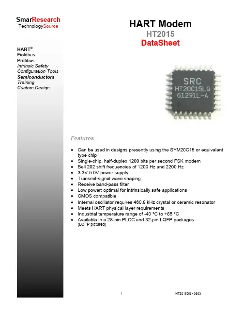
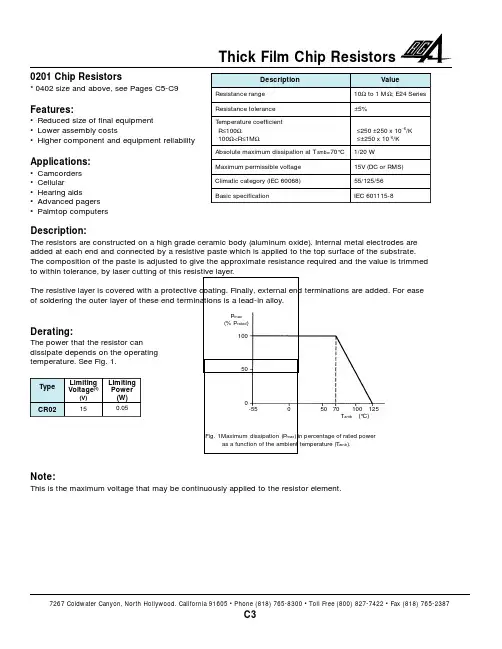
HART ® Fieldbus ProfibusIntrinsic SafetyConfiguration Tools Semiconductors TrainingCustom DesignSmar ResearchTechnology SourceFeatures• Can be used in designs presently using the SYM20C15 or equivalent type chip• Single-chip, half-duplex 1200 bits per second FSK modem • Bell 202 shift frequencies of 1200 Hz and 2200 Hz • 3.3V-5.0V power supply• Transmit-signal wave shaping • Receive band-pass filter• Low power: optimal for intrinsically safe applications • CMOS compatible• Internal oscillator requires 460.8 kHz crystal or ceramic resonator • Meets HART physical layer requirements• Industrial temperature range of -40 °C to +85 °C• Available in a 28-pin PLCC and 32-pin LQFP packages(LQFP pictured)HART ModemHT2015 DataSheetThe HT2015 is a single-chip, CMOS modem for use in Highway Addressable Remote Transducer (HART) field instruments and masters. The modem and a few external passive components provide all of the functions needed to satisfy HART physical layer requirements including modulation, demodulation, receive filtering, carrier detect and transmit-signal shaping. The HT2015 is pin-compatible with theSYM20C15. See the Pin Description and Functional Description sections for details on pin compatibility with the SYM20C15.The HT2015 uses Phase Continuous Frequency Shift Keying (FSK) at 1200 bits per second. To conserve power the receive circuits are disabled during transmit operations and vice versa. This provides the half-duplex operation used in HART communications.General DescriptionFig. 1 - 28 pin PLCC Pinout Package Fig. 2 - 32 pin LQFP Pinout PackageTable 1 - Pin DescriptionsSignalTypePLCC LQFP DescriptionTEST1 Input 1 28 Connect to Vss.TEST2 * 2 29 No connect. TEST3 * 3 31 No connect. TEST4 * 4 32 No connect.TEST5 Input 5 1 Connect to Vss.INRESETInput62Reset all digital logic when low.TEST7 Input 7 3 Connect to Vss. TEST8Input84Connect to Vss.TEST9 Input 9 5 Connect to Vss. OTXAOutput107Modulated output transmit analog. FSK modulated HARTtransmit signal to 4-20mA loop interface circuit.IAREF Input 11 8 Analog reference voltage. ICDREFInput129Carrier detect reference voltage.OCBIAS Output 13 10 Comparator bias current. TEST10Input1411Connect to Vss.VDDA Power 15 13 Analog supply voltage. IRXA Input 16 14 FSK modulated HART receive signal from 4-20mA loopinterface circuit. .ORXAF Output 17 15 Analog receiver filter input. IRXACInput1816Analog receive comparator input.OXTL Output 19 17 Crystal oscillator output. IXTLInput2018Crystal oscillator input.VSS Ground 21 6,20 Ground. VDDPower2221,30Digital supply voltage.INRTS Input 23 22 Request to send. ITXDInput2423Input transmit data. Transmitted HART data stream fromUART.TEST11 * 25 24 No connect. ORXD Output 26 25 Received demodulated HART data to UART. OCD Output 27 26 Carrier detect output. TEST12*2827No connect.VSSA Ground * 12,19 Analog ground.Pin Descriptions:IAREF: Analog Reference VoltageThis analog input sets the dc operating point of the operational amplifiers and comparators and is usually selected to split the dc potential between V DD and V SS. See IAREF in DC Characteristics on page 11.ICDREF: Carrier Detect Reference VoltageThis analog input controls at which level the carrier detect (OCD) becomes active. This is determined by the dc voltage difference between ICDREF and IAREF. Selecting ICDREF - IAREF equal to 0.08 V DC will set the carrier detect to a nominal 100 mV p-p.INRESET: Reset Digital LogicWhen at logic low (V SS) this input holds all the digital logic in Reset. During normal operation INRESET should be at V DD. INRESET should be held low for a minimum of 10 nS after V DD = 2.5 V as shown in Figure 3.INRTS: Request To SendThis active-low input selects the operation of the modulator. OTXA is enabled when this signal is low. This signal must be held high during power-up.IRXA*: Analog Receive InputThis input accepts the 1200/2200 Hz signals from the external filter. IRXAC: Analog Receive Comparator InputThis is the positive input of the carrier detect comparator and the receiver filter comparator.ITXD: Digital Transmit Input (CMOS) This input to the modulator accepts digital data in NRZ form. When ITXD is low, the modulator output frequency is 2200 Hz. When ITXD is high, the modulator output frequency is 1200 Hz.IXTL: Oscillator InputThis input to the internal oscillator must be connected to a parallel mode 460.8 kHz ceramic resonator when using the internal oscillator or grounded when using an external 460.8 kHz clock signal. OCBIAS: Comparator Bias CurrentThe current through this output controls the operating parameters of the internal operational amplifiers and comparators. For normal operation, OCBIAS current is set to 2.5 4A.OCD: Carrier Detect OutputThis output goes high when a valid input is recognized on IRXA. If the received signal is greater than the threshold specified on ICDREF for four cycles of the IRXA signal,the valid input is recognized. Figure 3 - Reset TimingO RXAF*: Analog Receive Filter OutputThis signal is the square wave output of the receiver high-pass filter.ORXD: Digital Receive Output (CMOS) This signal outputs the digital receive data. When the received signal (IRXA) is 1200 Hz, ORXD outputs logic high. When the received signal (IRXA) is 2200 Hz, ORXD outputs logic low. ORXD is qualified internally with OCD and is logic high when OCD is low.OTXA: Analog Transmit OutputThis output provides the trapezoidal signal controlled by ITXD. When ITXD is low, the output frequency is 2200 Hz. When ITXD is high, the output frequency is 1200 Hz. This output is active when INRTS is low and 0.5 V DC when INRTS is high. OXTL: Oscillator OutputThis output from the internal oscillator must be connected to an external 460.8 kHz clock signal or to a parallel mode 460.8 kHz ceramic resonator when using the internal oscillator. TEST(12:1): Factory TestThese are factory test pins. For normal operation, tie these signals as per Table 1.VDD: Digital PowerThis is the power for the digital modem circuitry.VDDA: Analog Supply VoltageThis is the power for the analog modem circuitry.VSS: GroundThis is the analog and digital ground. VSSA: Analog GroundThe HT2015 is a functional equivalent of the SYM20C15 HART Modem. It contains a transmit data modulator and signal shaper, carrier detect circuitry, analog receiver and demodulator circuitry and an oscillator, as shown in Figure 4.The internal HART modem modulates the transmit-signal and demodulates the receive signal. The transmit-signal shaper enables theHT2015 to transmit a HART compliant signal. The carrier is detected by comparing the receiver filter output with the difference between two external voltage references. The analog receive circuitry band-pass filters the received signal for input to the modem and the carrier detect circuitry. The oscillator provides the modem with a stable time base using either a simple external resonator or an external clock source.Functional DescriptionFigure 4 - HT2015 Block DiagramHT2015 LOGIC The modem consists of a modulator and demodulator. The modem uses shift frequencies of nominally 1200 Hz (for a 1) and 2200 Hz (for a 0). The bit rate is1200 bits/second.Modulator The modulator accepts digital data in NRZ form at the ITXD input and generates the FSK modulated signal at the OTXA output. INRTS must be a logic low for the modulator to be active.Demodulator The demodulator accepts an FSK signal at the IRXA input and reproduces the original modulating signal at the ORXD output. Thenominal bit rate is 1200 bits per second. Figure 5 illustrates the demodulation process. The output of the demodulator is qualified with the carrier detect signal (OCD), therefore, only IRXA signals large enough to be detected (100 mVp-p typically) by the carrier detect circuit produce received serial data at ORXD. Maximum demodulator jitter is 12 percent of one bit given input frequencies within HARTspecifications, a clock frequency of 460.8 kHz (±1.0 percent) and zero input (IRXA) asymmetry.Modem CharacteristicsFigure 5: Demodulator Signal TimingTRANSMIT–SIGNAL SHAPER The transmit-signal shaper generates a HART compliant FSKmodulated signal at OTXA. Figure 6 and Figure 7 show the transmit-signal forms of the HT2015. For IAREF = 1.235 V DC , OTXA will have a voltage swing from approximately 0.25 to 0.75 V DC .CARRIER DETECT CIRCUITRY The Carrier Detect Comparator shown in Figure 8 below generates logic low output if the IRXAC voltage is belowICDREF. The comparator output is fed into a carrier detect block (see Figure 4 on page 5). The carrier detect block drives the carrier detect output pin OCD high if INRTS is high and four consecutive pulses out of thecomparator have arrived. OCD stays high as long as INRTS is high and the next comparator pulse is received in less than 2.5 ms. Once OCD goesinactive, it takes four consecutive pulses out of the comparator to assert OCD again. Four consecutive pulses amount to 3.33 ms when the received signal is 1200 Hz and to 1.82 ms when the received signal is 2200 HZ.Figure 7 - OTXA Waveform (2200 Hz)Figure 6 - OTXA Waveform (1200 Hz)ANALOG RECEIVER CIRCUITRYVoltage References The HT2015 requires two voltage references, IAREF and ICDREF. IAREF sets the dc operating point of the internal operational amplifiers and comparators. A 1.235 V DC reference (Analog Devices AD589) is suitable as IAREF. The level at which OCD (carrier detect) becomes active is determined by the dc voltage difference (ICDREF - IAREF). Selecting a voltage difference of 0.08 V DC will set the carrier detect to a nominal 100 mV p-p .Bias Current Resistor The HT2015 requires a bias current resistor to beconnected between OCBIAS and V SS . The bias current controls the operating parameters of the internal operational amplifiers and comparators. The value of the bias current resistor is determined by the referencevoltage IAREF and the following formula:The recommended bias current resistor is 500 ohm; when IAREF is equal to 1.235 V DC . In Figure 8 all external capacitor values have a tolerance of ±5 percent and the resistors have a tolerance of ±1 percent, except the 3 ohm; which has a tolerance of ±5 percent. External to the HT2015, the filter exhibits a three-pole, high-pass filter at 624 Hz and a one-pole, low-pass filter at 2500 Hz.Internally, the HT2015 has a high-pass pole at 35 Hz and a low-pass pole at 90 kHz. The low-pass pole can vary as much as ±30 percent. The inputimpedance of the entire filter is greater than 150 ohm; at frequencies below 50 kHz.Figure 8 - Receive Filter SchematicR BIAS =OSCILLATOR The HT2015 requires a 460.8 kHz clock signal on OXTL. This can be provided by an external clock or external components may be connected to the HT2015 internal oscillator.Internal Oscillator Option The oscillator cell will function with either a 460.8 kHz crystal orceramic resonator. A parallel resonant ceramic resonator can be connected between OXTL and IXTL. Figure 9 illustrates the crystal option for clock generation using a 460.8 kHz (±I percent tolerance) parallel resonant crystal and two tuning capacitors. The actual values of the capacitors maydepend on the recommendations of the manufacturer of the resonator. Typically, capacitors in the range of 100 pF to 470 pF are used.External Clock Option It may be desirable to use an external 460.8 kHz clock as shown in Figure 10 rather than the internaloscillator because of the high cost and low availability of ceramic resonators. In addition, the HT2015 consumes less current when an external clock is used. Minimum current consumption occurs with the clock connected to OXTL and IXTL connected to V SS .Figure 10 -Oscillator with External ClockFigure 9 - Crystal OscillatorElectrical CharacteristicsT A Ambient -40 CABSOLUTE MAXIMUMS+85 T S Storage Temperature -55 150 CV DD Supply Voltage - .3 6.0 VV IN , V OUT DC Input, Output - .3 V DD + .3 VT L Lead Temperature (soldering) 250 CCautions:1. CMOS devices are damaged by high-energy electrostatic discharge. Devices must be stored in conductivefoam or with all pins shunted. Precautions should be taken to avoid application of voltages higher than themaximum rating. Stresses above absolute maximum ratings may result in damage to the device.2. Remove power before insertion or removal of this device. V IL Input Voltage, Low VDC CHARACTERISTICS(V DD = 3.0V to 5.5V, V SS = 0V, T A = -40C to +85C).3 * V DD V IH Input Voltage .7 * V DD VV OL Output Voltage, Low (IOL = .67mA) .4 VV OH Output Voltage, High (IOH = .67mA) 2.4 VC IN Input Capacitance Analog Input IRXA Digital InputpF3.0 - 5.5 3.0 - 5.5 3.0 - 5.5 3.0 - 5.5 2.9 253.5I IL/IH Input Leakage Current +/-500 nAI OLL Output Leakage Current +/-10 µAI DD Power Supply Current (RBIAS = 500k Ω, IAREF = 1.235V) 3.3 5.0 150 170 180 200µAIAREF Analog Reference 3.3 5.0 1.2 1.235 2.52.6 VICDREF * Carrier Detect Reference (IAREF = .08V)1.15 VOCBIAS Comparator Bias Current (RBIAS = 500k Ω, IAREF = 1.235V)2.5 µA* The HART specification requires Carrier Detect (OCD) to be active between 80 and 120 mV p-p.Setting ICDREF at IAREF—.08V DC will set the carrier detect to a nominal 100 mV p-p.Demodulator JitterConditions1. Input frequencies at 1200 Hz +/-10 Hz, 2200 Hz +/-20 Hz2. Clock frequency of 460.8 kHz +/-0.1%3. Input (HLXA) asymmetry, 0 % of 1 bitMODEM CHARACTERISTIC(V DD = 3.0V to 5.5V, V SS = OV, T A = -40 C to +85 C)12 ResonatorToleranceFrequency 460.8% kHzCERAMIC RESONATOR - EXTERNAL CLOCK SPECIFICATIONS(V DD = 3.0V to 5.5V, V SS = OV, T A = -40 C to +85 C)1.0ExternalClock Frequency Duty Cycle Amplitude456.240460.850V OH - V OL465.460kHz%V AC CHARACTERISTICS(V DD = 3.0V to 5.5V, V SS = 0V, T A = -40C to +85C)IRXA Receive Analog InputLeakage CurrentFrequency - Mark (Logic 1) Frequency - Space (Logic 0) 1190218012002200+/-15012102220nAHzHzORXAF Output of the High-pass FilterSlew RateGain Bandwidth (GBW) Voltage Range 150.15.025V DD - .15V/µskHzV/µsIRXAC Carrier Detect & Receive Filter InputLeakage Current+/-500 nA OTXA ModulatorOutputFrequency * - Mark (Logic 1)Frequency - Space (Logic 0)Amplitude (IAREF 1.235 V)SlopeLoading (IAREF = 1.235 V) 30 1196.92194.35002.79HzHzmV p-pmV/µskΩORXD ReceiveDigitalOutputRise/Fall Time 20nsOCD Carrier Detect OutputRise/Fall Time 20ns * The modular output frequencies are proportional to the input clock frequency (460.8 kHz)Mechanical SpecificationFigure 11 - 28-pin PLCC Mechanical SpecificationA .165 .172 .180A 1 .099 .101 .110D .485 .490 .495D 1 .450 .452 .455D 2 .390 .420 .430D 3E .485 .490 .495E 1 .450 .452 .455E 2 .390 .420 .430E 3 .300 REFe .050 BSC.300 REFFigure 12 - 32-pin LQFP Mechanical SpecificationA - - 1.60A 1 .05 .01 .15A 2 1.35 1.40 1.45D 9.00 BSCD /2 4.50 BSCD 1 7.00 BSCE 9.00 BSCE /2 4.50 BSCE 1 L .45 .60 .75e .80 BSCb .30 .37 .45c .09 - .20ccc - - .10ddd - - .207.00 BSCSmar Research Corporation4250 Veterans Memorial HighwayHolbrook, NY USA 11741Tel: 631.737.3111 Fax: 631.737.3892techinfo@Smar Research reserves the right to make changes to design and functionality of any product without notice. Smar Research does not assumeany liability arising out of the application or use of any product. Smar Research , Technology Source, and the SRC logo are registered trademarks of Smar Research Corporation. The HART, Fieldbus, and Profibus Foundation logos are trademarks of their respective owners.。
目前EDP信号液晶屏主要有以下型号:M116NWR1 R5 龙腾11.6"液晶屏1366×768N133HSG-DJ1 奇美13.3"液晶玻璃1920×1080B156XW02 V2 HW0A 友达15.6"液晶屏1366×768N156BGE-E21 奇美15.6"液晶屏1366×768B140XTN01.0 友达14.0"液晶屏1366×768LTN141AT16-003 002 001三星14.1"液晶屏1280×800LP140WD1-TPD1 LG14.0"液晶屏1600×900B131HW02 V0 友达13.1"液晶屏1920×1080B131HW01 V0 友达13.1"液晶屏1920×1080CLAA133UA03 中华映管13.3"液晶屏1600×900LP133WP1-TPB1 LG13.3"液晶屏1440×900LP116WH4-TJA1 TLA2 TPA1 LG11.6"液晶玻璃1366×768 LTN116AT01-A04 三星11.6"液晶屏1366×768B141PW04 V1 HW0A 友达14.1"液晶屏1440×900LP156WH6-TJA1 LG15.6"液晶玻璃1366×768B116XW05 V004 V001 V1 V6友达11.6"液晶1366×768B141EW05 V5 友达14.1"液晶屏1280×800B160HW02 V0 友达16.0"液晶屏1920×1080LP173WF2-TPB2 TPA1 LG17.3"液晶屏1920×1080LM215WF3-SDC2 LG21.5"液晶屏1920×1080B121EW09 V4 友达12.1"液晶屏1280×800LP141WP2-TPA1 LG14.1"液晶屏1440×900CLAA215FS05 中华映管21.5"液晶屏1920×1080LTN133AT17-102 三星13.3"液晶屏1366×768N141I6-D11 奇美14.1"液晶屏1280×800N173HHF-E21 奇美17.3"液晶屏1920×1080LP133WH1-TPD1 LG13.3"液晶屏1366×768LP156WH2-TPB1 LG15.6"液晶屏1366×768LP156WD1-TPB1 LG15.6"液晶屏1600×900LP156WF1-TPB1 LG15.6"液晶屏1920×1080LP141WX5-TPP1 LG14.1"液晶屏1280×800LP133WP1-TPA1 LG13.3"液晶屏1440×900LTM190BT02 三星19.0"液晶屏1440×900LP121WX3-TPB1 LG12.1"液晶屏1280×800HV121WX5-120 121 HYDIS12.1"液晶屏1280×800B140XW01 V4 友达14.0"液晶屏1366×768B140RW01 V2 友达14.0"液晶屏1600×900LTN141AT08-301 AT09-301 三星14.1寸液晶屏1280X800B156XTN03.1 友达15.6寸液晶屏1366X768CLAA156WA12 12A 中华映管15.6"液晶屏1366×768LM270WQ1-SDB1 SDC1 SDE3 SDC2 SDA1 SDA2 LG27.0"液晶屏2560×1440 LM300WQ5-SDA1 LG30.0"液晶屏2560×1600M190PP01 V0 友达19.0"液晶屏1440×900LM240WU6-SDA1 LG24.0"液晶屏1920×1200LM215WF3-SDA1 LG21.5"液晶屏1920×1080CLAA220WA11 中华映管21.6"液晶屏1680×1050CLAA173UA12 中华。
数据手册DATASHEET8022WS单键单输出LED调光触摸芯片(Rev:1.3)一、概述8022WS触摸感应IC是为实现人体触摸界面而设计的集成电路。
可替代机械式轻触按键,实现防水防尘、密封隔离、坚固美观的操作界面。
使用该芯片可以实现LED 灯光的触摸开关控制和亮度调节。
方案所需的外围电路简单,操作方便。
确定好灵敏度选择电容,IC就可以自动克服由于环境温度、湿度、表面杂物等造成的各种干扰,避免由于电阻、电容误差造成的按键差异。
二、特性1、工作电压范围:2.2~5.5V。
2、待机功耗低:V DD=5V,待机电流14uA;V DD=3V,待机电流7uA。
3、工作温度:-25℃~85℃。
4、HBM ESD:±4KV以上。
5、按键响应时间:小于100ms。
6、灯光亮度可根据需要随意调节,选择范围宽,操作简单方便。
7、控制信号输出频率达32KHz,无频闪现象。
8、封装类型:SOP8。
9、内置稳压源、上电复位、低压复位、环境自适应算法等多种措施,可靠性高。
10、抗电源干扰及手机干扰特性好,近距离、多角度手机干扰情况下触摸响应灵敏度及可靠性不受影响。
11、高灵敏度(用户可自行调节)。
12、高防水性能。
13、应用电路简单,外围器件少,成本低。
14、按键感应盘大小:大于3mm*3mm,根据不同面板材质跟厚度而定,可以直接用大面积金属片。
15、按键感应盘间距:大于2mm。
16、按键感应盘形状:任意形状(必须保证与面板的接触面积)。
17、按键感应盘材料:PCB铜箔,金属片,平顶圆柱弹簧,导电橡胶,导电油墨,导电玻璃的ITO层等。
18、面板厚度:0~12mm,根据不同的面板材质有所不同。
19、面板材质:绝缘材料,如有机玻璃,普通玻璃,钢化玻璃,塑胶,木材,纸张,陶瓷,石材等。
20、芯片内置防水工作模式。
在防水模式下,无论面板上有溅水、漫水甚至完全被水淹没,按键都可以正确快速的响应。
不同于目前一般感应按键在面板溅水、漫水时容易误动作,积水后反应迟钝或误响应的情况。
Thermal ImagerKT -80index:WMXXKT80Product features• a friendly interface that is easy to use without special training• a quick and inexpensive way to start performing infrared diagnostic tests • replaceable high-capacity Li-ion accumulator • over 4 hours of continuous operation• large 3.5-inch screen with high brightness • durable rubber-lined housing• micro USB interface for transmitting data and charging the accumulator • Wi-Fi wireless connectivity (optional)Measure temperature of objects with the KT-80 Thermal ImagerThermal specificationlens8 mm detector resolution ≤ 80 x 80 px spectral range 8-14 µm focusmanual focal length / FOV 8 mm / 18.5° x 18.5°thermal sensitivity ≤ 0.08°C @30°Cdigital zoom ―palette 4interfacemicro-USBApplicationThe Sonel KT-80 thermal imager is budget-friendly yet offers highly accurate temperature measurements. Robustly designed and constructed it is ideally suited for:• troubleshooting electrical installations, wiring, panels, motors, breakers, trans-formers, switchgear and electrical equipment,• monitoring the thermal performance of industrial manufacturing processes,• identifying overheating of mechanical and electro-mechanical components,• inspecting buildings for insulation leaks, energy audits, water damage, and pests,• locating hidden heat sources (of people, animals, objects) in dark / low-light conditions.Analytic software includedThe Sonel ThermoAnalyze 2 PC software is supplied with the camera. It allows to perform detailed analysis of the recorded thermal images, followed by gen-erating thermal inspection report.Single-hand operationThe user-friendly design and intuitive handling make the thermal imager a pleasure to use. Experienced or new users needing a professional diagnostic tool will find the user interface easy to use without training. The included Ther -moAnalyze 2 software for the PC allows further analysis and the preparationof reports.Display specificationdisplay high-brightness 3.5’’ LCD, three step backlitresolution 320 x 240 pxframe refresh50 HzTemperature measurement parametersaccuracy ±3.6°F (±2°C) or ±2% of reading for ambient temperaturefrom range 50...95°F (10…35°C),otherwise ±5.4°F (±3°C) or ±3% of reading;distance 3.3...16.4 ft (1...5 m)temp. range32...482°F (0...+250°C)measurement parameter calibration emissivity adjustable (0.01...1.00)min. distance4” (10 cm)Measurement functionspoint central point temperature max area auto trackingmin area auto trackingfile format / storage JPG / removable SD memorycardpower system3,7 V 4200 mAh Li-Ion battery,run time over 4 hourscharging system in-camera charging, externalbattery charger (option) power adapter110/230 VAC, 50/60 Hz Other technical dataingress protection acc. to EN 60529IP43 dimensions4.3” x 3.8” x 10.2”(103 mm x 98 mm x258 mm) weight 1.7 lbs (755 g)operating temperature12...122°F(-10...+50°C)storage temperature-4...140°F(-20...+60°C)humidity10%...95% withoutcondensation shock25G, IEC 68-2-29 vibration2G, IEC 68-2-6Li-ion rechargeablebattery3.7 V4.2 AhWAAKU13micro-USB data transmission cable WAPRZUSBMICROSonel ThermoAna-lyze 2 PC software WAPROTHERMOANALYZE2SD memory cardWAPOZSD1hand strapWAPOZPAS1Standard accessoriespower adapter100~240V (withadapters for dif-ferent sockets)Additional accessoriesPower supplyadaptor Z12WAZASZ12Wi-Fi SD card 4 GBWAPOZSDWIFI4L3 carrying caseWAWALL3Wi-Fi SD card 8 GBWAPOZSDWIFI8。