深海控制器DSE7320产品功能介绍
- 格式:pdf
- 大小:304.23 KB
- 文档页数:12
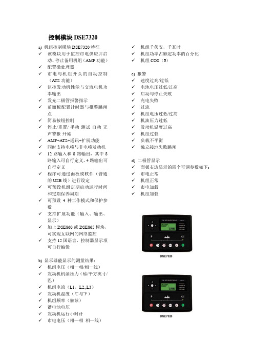
控制模块DSE7320a) 机组控制模块DSE7320特征✓该模块用于监控市电供应并启动、停止备用机组(AMF功能)✓配置微处理器✓市电与机组开头的自动控制(A TS功能)✓监控发动机性能与交流电机功率输出✓发光二极管报警指示✓前面板配置计时器与报警跳闸点✓简易按钮控制✓停止/重置/-手动-测试-自动-无声警报-开始✓AMF+A TS+通讯+扩展功能✓同时支持电喷与非电喷发动机✓12路输入和8路输出,其中8路输入可自行定义,4路输出可自行定义✓程序可通过面板或软件(普通的USB线)进行设定✓可预设机组定期启动运行时间和定期保养周期✓可预设4种工作模式和保护参数✓支持扩展功能(输入、输出、显示)✓加上DSE860或DSE865模块,可实现互联网的网络监控✓支持12国语言,控制器显示项可自行编辑b) 显示器能显示的测量结果:✓机组电压(相—相/相—线)✓发动机机油压力(磅/平方英寸/巴)✓机组电流(L1,L2.,L3)✓发动机温度(℃与℉)✓机组频率(赫兹)✓蓄电池电压✓发动机运行小时计✓市电电压(相—相相—线)✓机组千伏安,千瓦时✓机组功率占额定功率的百分比✓机组COS(δ)c) 报警✓速度过高/过低✓电池电压过低/过高✓启动与停止失败✓充电失败✓过流✓机组电压过低/过高✓机油压力过低✓发动机温度过高✓机组过载✓负载不平衡✓独立接地失败跳闸d) 二极管显示✓面板右边显示的四个可调参数如下:✓市电正常✓机组正常✓市电加载✓机组加载。
深海控制器 DSE8610模块功能介绍DSE POWER® 优控系列 DSE8610 自启动负载分配模块一、DSE8610功能介绍 二、DSE8610监控方式一、DSE8610功能介绍1、 多端口可同时使用- RS232、 RS485、USB和网络端口 2、 具有数据采集和分析功能(data logging ) 3、 超强的PLC逻辑功能 4、 DSE8610模块的兼容性 5、 模块与调速器、调压板直接相连 6、 负载分配特性 7、 其他功能1、 多端口可同时使用- RS232、 RS485、网络端口、USB和程序设定端口2、 具有数据采集和分析功能(data logging )3、 超强的PLC逻辑功能举例:①当发动机的水温大于100°C,机组以额定功率的60%输出②当发动机的水温小于95°C,机组以额定功率的90%输出4、 DSE8610模块的兼容性5、 模块与调速器、调压板直接相连5.1 模块与调速器、调压板直接相连5.2 模块与数字调速器、数字调压板直接相连6、 负载分配特性6.1 自动模式下三种启动方式 ① 远程启动信号设置为Remote start on load ,无论哪台机组如果远程信号有效,都会自启动,然后并联。
接线如下图:② 远程启动信号设置为Remote start on load demand,根据负载 的大小,自动调用或停止除主机之外其它机组 。
接线如下图:软件设置如下图:③ 远程启动信号设置为Remote start on load demand,刚开始启动时,启动 所有的机组,然后根据负载的大小,自动调用或停止除主机之外其它机 组 。
接线如下图:软件设置如下图:6.2 削峰调节白天傍晚/黄昏晚上/夜间白天傍晚/黄昏晚上/夜间DSE8610负载分配百分比DSE8610负载分配百分比7、 其他功能7.1 可设4套工作模式和保护参数可预设4种工作模式和保护参数。
1 概述本仪表为反渗透控制器和在线电导率仪表的组合式控制仪表。
可完成RO系统的运行检测、状态控制和水质电导率的在线监控(将PLC控制器和电导率仪合二为一);形象的流程图形控制面板,以LED指示灯镶嵌,界面友好;菜单式操作,多组参数设置,可满足自动运行的各项要求。
2 流程选择RO系统有以下两种典型工作模式(如图A、B),本RO控制器对图A、图B两种模式都能兼顾。
3 功能及主要技术指标无水保护功能:如原水断水,“LOW FEED PRESS”灯点亮,数码管显示“ALA”,蜂鸣器报警,控制器关闭整个RO系统。
此后控制器将不间断检测无水开关,如供水恢复则重新启动系统。
低压保护功能:如低压不足,“LOW PRESS”灯点亮,数码管显示“ALA”,蜂鸣器报警,控制器关闭整个RO系统,控制器1分钟后进行首次试启动,如水压满足则恢复制水过程。
如果3次启动不成功,系统进入死锁状态,复位CON或按复位键退出,重新启动。
高压保护功能:如高压超压,“HIGH PRESS”灯点亮,数码管显示“ALA”,蜂鸣器报警,控制器关闭整个RO系统,等待高压消除。
高压消除后,控制器1分钟后进行首次试启动,如水压正常则恢复制水过程。
如果3次启动不成功,系统进入死锁状态。
复位CON或按复位键退出,重新启动。
电导率越限报警功能:当被测溶液的电导率值大于限值时,面板上“HIGH”灯点亮,蜂鸣器报警,控制继电器吸合(此继电器可驱动打开旁路阀)。
小于限值时,报警解除。
主要技术指标:1)电源电压:AC 220V±15% 50Hz 功耗:≤3W2)环境条件:a)温度:0~50℃;b)湿度:≤85%RH3)测量范围: 0~200μS /cm4)准确度:1.5级5)输出接点负载能力:3A/250V AC (电磁阀须通过中间继电器驱动) 6)电导池工作压力:0~0.5Mpa7)介质温度:5~50℃8)温度补偿:以25℃为基准,自动温度补偿9)测量距离:不大于30m(除另有约定外,电极电缆出厂配置5m)10)显示方式:31-2位LED数字显示11)选配电极: 1.0cm-112)外形尺寸:96×96×110mm(高×宽×深)13)表盘开孔:92×92mm(高×宽)4 前面板说明图3 前面板显示板如上图,由上到下共分为I、II、III三个区域。
深海控制器说明书篇一:深海5110控制器5110使用说明书一、按钮符号说明二、状态/测量单位符号说明三、故障符号说明四、操作说明 1、手动模式:按动?按动?按动? 机组进入手动启动状态;机组正在手动运行状态 ?按动按动? 机组进入停车状态。
? 监测到模块端号102、自动模式:?按动的输入有效或常用电源故障 ? 机组进入自动启动状态;机组正在自动运行状态 ? 监测到模块端号10的输入无效或常用电源故障恢复 ? 机组进入冷机状态 ? 机组进入自动停车状态。
3、手动启动转自动模式:按动?按动?按动? 机组进入手动启动状态 ? 机组进入手动运行状态 ?按动按动? 机组进入自动运行状态。
4、故障清除及系统复位:? 清除故障报警状态,系统复位之后进入停车状态。
五、典型应用接线图篇二:深海7320控制器接线图深海7320控制器接线图:篇三:英国深海DSE5110控制器自动化控制器介绍(英国深海DSE51101、概述控制器)英国深海DSE5110是一个发动机自动控制模块,该模块可被OEM商用于大多数复杂的工业控制。
它能自动启动和停止发动机,指示发动机的工作状态和故障情况。
当发动机出现停机故障时,能自动停机并通过面板上的液晶显示屏和闪烁的LED指示灯来指示发动机的故障情况。
客户可在控制面板上进行编辑来改变操作定时时间和故障报警类型,而不需要其它的特别设备。
用户可通过面板上的“停机”、“自动”、和“手动”按钮来操作模块。
液晶显示屏旁边的向下翻页按钮用于滚动液晶显示屏来察看更多的仪表测量数据。
测量数据显示信息及测量数据报警显示图标该模块采用微处理器控制技术,并提供多个定时器和预设定程序清单,可使用户实现较复杂的控制功能。
控制器LCD液晶显示功能:发电机组三相相电压L1-N, L2-N, L3-N 发电机组三相线电压L1-L2, L2-L3, L3-L1 发电机组三相电流 L1, L2, L3 发电机组频率 Hz 发动机转速 RPM 发动机机油压力发动机冷却水温度电池电压发动机运行小时模块报警保护功能:超速/欠速充电(本文来自:小草范文网:深海控制器说明书)故障紧急停车低油压高水温启动失败恢复停车失败转速序号丢失另外,指示、告警或停机等可设定的报警输入均能通过液晶显示屏和LED指示灯来标识。

DSE POWER ®DSE7520 MK1 Mains Control ModuleDocument Number 057-090Author : Anthony MantonDeep Sea Electronics PlcHighfield HouseHunmanbyNorth YorkshireYO14 0PHENGLANDSales Tel: +44 (0) 1723 890099Sales Fax: +44 (0) 1723 893303E-mail: sales@Website: DSE Model 7520MK1 AMF controller operator manual© Deep Sea Electronics PlcAll rights reserved. No part of this publication may be reproduced in any material form (including photocopying or storing in any medium by electronic means or other) without the written permission of the copyright holder except in accordance with the provisions of the Copyright, Designs and Patents Act 1988. Applications for the copyright holder’s written permission to reproduce any part of this publication should be addressed to Deep Sea Electronics Plc at the address above.The DSE logo and the names DSEUltra, DSEControl, DSEPower, DSEExtra, DSEMarine and DSENet are UK registered trademarks of Deep Sea Electronics PLC.Any reference to trademarked product names used within this publication is owned by their respective companies.Deep Sea Electronics Plc reserves the right to change the contents of this document without prior notice. Amendments since last publicationAmd. No. Comments1 Converted 5520 V8 manual to 7520 V102 Update to wiring diagrams (issue10.1)2057-0907520 OPERATING MANUAL ISSUE 10.1 06/11/08 AMTABLE OF CONTENTSSection Page 1BIBLIOGRAPHY (5)2INTRODUCTION (6)3SPECIFICATIONS (7)3.1PART NUMBERING (7)3.1.1SHORT NAMES (7)3.1POWER SUPPLY REQUIREMENTS (8)3.2TERMINAL SPECIFICATION (8)3.3GENERATOR VOLTAGE / FREQUENCY SENSING (8)3.4INPUTS (8)3.4.1DIGITAL INPUTS (8)3.4.2CHARGE FAIL INPUT (9)3.4.3MAGNETIC PICKUP (9)3.5OUTPUTS (9)3.5.1OUTPUTS A & B (FUEL AND START) (9)3.5.2CONFIGURABLE OUTPUTS C & D (LOAD SWITCHING) (9)3.5.3CONFIGURABLE OUTPUTS E, F & G (9)3.6COMMUNICATION PORTS (10)3.7ACCUMULATED INSTRUMENTATION (10)3.8SOUNDER (10)3.9DIMENSIONS AND MOUNTING (11)3.9.1FIXING CLIPS (12)3.9.2CABLE TIE FIXING POINTS (13)3.9.3SILICON SEALING GASKET (13)3.10APPLICABLE STANDARDS (14)4INSTALLATION (15)4.1USER CONNECTIONS (15)4.1.1DC SUPPLY, FUEL AND START OUTPUTS, OUTPUTS E,F,G (16)4.1.2ANALOGUE SENSOR (16)4.1.3MAGNETIC PICKUP, CAN AND EXPANSION (17)4.1.4LOAD SWITCHING AND GENERATOR VOLTAGE SENSING (18)4.1.5BUS / MAINS VOLTAGE SENSING (18)4.1.6GENERATOR CURRENT TRANSFORMERS (19)4.1.7MAINS CURRENT TRANSFORMERS (19)4.1.8CONFIGURABLE DIGITAL INPUTS (20)4.1.9PC CONFIGURATION INTERFACE CONNECTOR (21)4.1.10EXPANSION INTERFACE CONNECTOR (21)4.1.11RS485 CONNECTOR (22)4.1.12RS232 CONNECTOR (22)4.1.13ENGINE CONTROL UNIT INTERFACE (23)4.1.14LED INDICATORS AND LOGO INSERT (24)4.2TYPICAL WIRING DIAGRAMS (25)4.2.1 3 PHASE, 4 WIRE WITH RESTRICTED EARTH FAULT PROTECTION (25)4.3ALTERNATIVE TOPOLOGIES (26)4.3.1 3 PHASE, 4 WIRE WITHOUT EARTH FAULT PROTECTION (26)4.3.2SINGLE PHASE WITH RESTRICTED EARTH FAULT (27)4.3.3SINGLE PHASE WITHOUT EARTH FAULT (27)4.3.4 2 PHASE (L1 & L2) 3 WIRE WITH RESTRICTED EARTH FAULT (28)4.3.5 2 PHASE (L1 & L2) 3 WIRE WITHOUT EARTH FAULT (28)4.3.6 2 PHASE (L1 & L3) 3 WIRE WITH RESTRICTED EARTH FAULT (29)4.3.7 2 PHASE (L1 & L3) 3 WIRE WITHOUT EARTH FAULT MEASURING (29)4.3.8 3 PHASE 4 WIRE WITH UNRESTRICTED EARTH FAULT MEASURING (30)5OPERATION (31)5.1CONTROL (31)057-0907520 OPERATING MANUAL ISSUE 10.1 06/11/08 AM 35.1.1DESCRIPTION OF CONTROLS (32)6CONTROL PUSH-BUTTONS (33)6.1AUTOMATIC OPERATION (35)6.1.1MAINS FAILURE (35)6.1.2REMOTE START IN ISLAND MODE (37)6.1.3REMOTE START ON LOAD (39)6.2MANUAL OPERATION (41)6.3TEST OPERATION (43)7PROTECTIONS (45)7.1WARNINGS (46)7.2ELECTRICAL TRIPS (47)7.3ROCOF / VECTOR SHIFT (48)7.3.1MAINS DECOUPLING TEST MODE (48)7.3.2SYNCHROSCOPE OPERATION (49)7.4COMPLETE INSTRUMENTATION LIST (50)7.4.1BASIC INSTRUMENTATION (50)7.5THE FRONT PANEL CONFIGURATION EDITOR (51)7.5.1ACCESSING THE FRONT PANEL CONFIGURATION EDITOR. (51)7.5.2LIST OF ADJUSTABLE PARAMETERS IN ‘MAIN CONFIGURATION EDITOR’ (52)7.6RUNNING EDITOR (53)7.6.1ACCESSING THE ‘RUNNING’ CONFIGURATION EDITOR (53)8COMMISSIONING (54)8.1COMMISSIONING SCREENS (54)8.1.1SCREEN 1 (54)8.1.2SCREEN 2 (54)8.1.3SCREEN 3 (54)9FAULT FINDING (55)10APPENDIX (56)10.17520MK1 IDMT TRIPPING CURVES (TYPICAL) (56)10.27520MK1 SHORT CIRCUIT TRIPPING CURVES (TYPICAL) (56)10.3ACCESSORIES (57)10.3.1OUTPUT EXPANSION (57)RELAY OUTPUT EXPANSION (157) (57)LED OUTPUT EXPANSION (548) (57)10.3.2INPUT EXPANSION (P130/P540/P541) (57)10.4COMMUNICATIONS OPTION (58)10.4.1DESCRIPTION (58)10.4.2CONTROLLER TO PC (DIRECT) CONNECTION (58)10.4.3CONTROLLER TO MODEM CONNECTION (59)10.4.4RS485 LINK TO CONTROLLER (60)TYPICAL BUILDING MANAGEMENT SCHEME USING RS485 MONITORING (61)10.4.5MODBUS (61)10.5ENCLOSURE CLASSIFICATIONS (62)IP CLASSIFICATIONS (62)NEMA CLASSIFICATIONS (63)10.6IEEE C37.2 STANDARD ELECTRICAL POWER SYSTEM DEVICE FUNCTION NUMBERS (64)4057-0907520 OPERATING MANUAL ISSUE 10.1 06/11/08 AM1 BIBLIOGRAPHYThis document refers to and is referred to by the following DSE publications which can be obtainedfrom the DSE website 053-053 DSE7520 installation instructions057-004 Electronic Engines and DSE wiring manual057-078 DSE7500 Series Configuration Suite manual057-046 DSE Guide to Synchronising and Load Sharing Part 2 – Governor and AVR Interfacing056-047 Load Share Design and Commissioning053-055 DSE850 installation instructions053-040 DSE157 expansion relay board installation instructions051-157 DSE130 input expansion module installation instructionsAdditionally this document refers to the following third party publicationsISBN 1-55937-879-4IEEE Std C37.2-1996 IEEE Standard Electrical Power System Device Function Numbers and Contact Designations. Institute of Electrical and Electronics Engineers IncISBN 0-7506-1147-2 Diesel generator handbook. L.L.J.MahonISBN 0-9625949-3-8 On-Site Power Generation. EGSA Education Committee.057-0907520 OPERATING MANUAL ISSUE 10.1 06/11/08 AM 52 INTRODUCTIONThis document details the installation and operation requirements of the DSE7500 Series modules, part of the DSEPower® range of products.The manual forms part of the product and should be kept for the entire life of the product. If the product is passed or supplied to another party, ensure that this document is passed to them for reference purposes.This is not a controlled document. You will not be automatically informed of updates. Any future updates of this document will be included on the DSE website at The DSE7520 Mk1 controller is an update to the popular DSE5520. It maintains all the functions and flexibility of the DSE5520 while being packaged in DSE7000 series styling bringing with it the advantages of the DSE7000 series terminal compatibility easing system upgrades.The DSE7520 is NOT for use in a multiple generator load share system.The DSE 7520MK1 Module allows the OEM to meet demand for increased capability within the industry. It allows the user to start and stop the generator and if required, transfer the load to the generator either manually or automatically. The user also has the facility to view the system operating parameters via the LCD display.Utilising the inbuilt synchronising, volts matching and paralleling functions, the controller is able to parallel with the mains supply for peak.The DSE 7520MK1 module also monitors the engine, indicating the operational status and fault conditions, automatically shutting down the engine. Exact failure mode information is indicated by the LCD display on the front panel.The powerful Microprocessor contained within the module allows for many features to be incorporated as standard;•Full Multilingual LCD display (including non-western character fonts).•True R.M.Ss. voltage monitoring.•Power measurement.•Communications capability (RS485 or RS232)•Check Sync capability•Automatic Sync capability•Load control capability•Fully configurable inputs for use as alarms or a range of different functions also available on P130 expansion inputs (optional)•Extensive range of output functions using built in relay outputs or relay expansion available. •Instrumentation and diagnostics from electronic engines when connected to an engine ECU. Selective operational sequences, timers and alarm trips can be altered by the customer via a PC using the 75xx For Windows ™ software and 810 interface or via the integral front panel configuration editor.Access to critical operational sequences and timers for use by qualified engineers, can be protected by a security code. Module access can also be protected by PIN code. Selected parameters can be changed from the module’s front panel.The module is housed in a robust plastic case suitable for panel mounting. Connections to the module are via locking plug and sockets.6057-0907520 OPERATING MANUAL ISSUE 10.1 06/11/08 AM057-090 7520 OPERATING MANUAL ISSUE 10.1 06/11/08 AM 73 SPECIFICATIONS3.1 PART NUMBERING-At the time of this document production, there have been no revisions to the module hardware.3.1.1 SHORT NAMESDescription DSE7000All modules in the DSE7000 Series DSE7500All modules in the DSE7500 sync/load share range DSE7520DSE7520 moduleDSE 7520 AMFcontroller andATS ModuleRevision 13.1 POWER SUPPLY REQUIREMENTS Minimum supply voltage 8V continuousCranking dropouts Able to survive 0V for 50mS providing the supply was at least 10V before the dropout and recovers to 5V afterwards.Maximum supply voltage 35V continuous (60V protection) Reverse polarity protection -35V continuousMaximum operating current TBAmA at 24V TBAmA at 12VMaximum standby current TBAmA at 24V TBAmA at 12VPlant supply instrumentation displayRange 0V-60V DC (note Maximum continuous operating voltage of 35V DC) Resolution 0.1VAccuracy 1% full scale3.2 TERMINAL SPECIFICATIONConnection type Screw terminal, rising clamp, no internal springMin cable size 0.5mm² (AWG 24)Max cable size 2.5mm² (AWG 10)3.3 GENERATOR VOLTAGE / FREQUENCY SENSINGMeasurement type True RMS conversionSample Rate 5KHz or betterHarmonics Up to 10th or betterInput Impedance 300K Ω ph-NPhase to Neutral 15V to 333V AC (max)Phase to Phase 25V to 576V AC (max)Common mode offsetfrom Earth100V AC (max)Resolution 1V AC phase to neutral2V AC phase to phaseAccuracy ±1% of full scale phase to neutral±2% of full scale phase to phaseMinimum frequency 3.5HzMaximum frequency 75.0HzFrequency resolution 0.1HzFrequency accuracy ±0.2Hz3.4 INPUTS3.4.1 DIGITAL INPUTSNumber 9Arrangement Contact between terminal and groundLow level threshold 40% of DC supply voltageHigh level threshold 60% of DC supply voltageMaximum input voltage DC supply voltage positive terminalMinimum input voltage DC supply voltage negative terminalContact wetting current 2.5mA @12V typical5mA @ 24V typicalOpen circuit voltage Plant supply8057-0907520 OPERATING MANUAL ISSUE 10.1 06/11/08 AM3.4.2 CHARGE FAIL INPUTMinimum voltage 0VMaximum voltage 35V (plant supply)Resolution 0.2VAccuracy ± 1% of max measured voltageExcitation Active circuit constant power outputOutput Power 2.5W Nominal @12V and 24VCurrent at 12V 210mACurrent at 24V 105mA3.4.3 MAGNETIC PICKUPType Single ended input, capacitive coupledMinimum voltage 0.5V RMSMax common mode voltage ±2VMaximum voltage Clamped to ±70V by transient suppressers, dissipation not to exceed 1W. Maximum frequency 10,000HzResolution 6.25 RPMAccuracy ±25 RPMFlywheel teeth 10 to 5003.5 OUTPUTS3.5.1 OUTPUTS A & B (FUEL AND START)Type Fuel (A) and Start (B) outputs. Supplied from DC supply terminal 2.Rating 3A @ 35VProtection Protected against over current & over temperature. Built in load dump feature.3.5.2 CONFIGURABLE OUTPUTS C & D (LOAD SWITCHING)Type Fully configurable volts free relays. Output C – Normally Closed, Output D –Normally OpenRating 8A @ 230V ACProtection Protected against over current & over temperature. Built in load dump feature.3.5.3 CONFIGURABLE OUTPUTS E, F & GType Fully configurable, supplied from DC supply terminal 2.Rating 3A @ 35VProtection Protected against over current & over temperature. Built in load dump feature.057-0907520 OPERATING MANUAL ISSUE 10.1 06/11/08 AM 910 057-090 7520 OPERATING MANUAL ISSUE 10.1 06/11/08 AM3.6 COMMUNICATION PORTS810 portFor connection to the DSE810 interface only Expansion portFor connection to DSE130, DSE157, DSE545, DSE548 expansion modules only DSENetDSE7510 Mk1 controller does nothave DSENet expansion capability CAN PortEngine CAN Port Standard implementation of ‘Slow mode’, up to 250K bits/s Non Isolated. Internal Termination provided (120Ω) RS485 SerialIsolated Data connection 2 wire + commonHalf DuplexData direction control for Transmit (by s/w protocol)Max Baud Rate 19200External termination required (120R)Max common mode offset 70V (on board protection transorb) Max distance 1.2km (¾ mile)3.7 ACCUMULATED INSTRUMENTATIONEngine hours runMaximum 99999 hrs 59 minutes (approximately 11yrs 4months) Number of starts1,000,000 (1 million)3.8 SOUNDERDSE7000 Series features an internal sounder to draw attention to warning, shutdown and electrical trip alarms.Sounder level 84db @ 1m057-090 7520 OPERATING MANUAL ISSUE 10.1 06/11/08 AM 113.9 DIMENSIONS AND MOUNTINGDIMENSIONS240.0mm x 181.1mm x 41.7mm (9.4” x 7.1” x 1.6”)PANEL CUTOUT220mm x 160mm (8.7” x 6.3”)WEIGHT0.7kg (1.4lb)12 057-090 7520 OPERATING MANUAL ISSUE 10.1 06/11/08 AM3.9.1 FIXING CLIPSThe module is held into the panel fascia using the supplied fixing clips.• Withdraw the fixing clip screw (turn anticlockwise) until only the pointed end is protrudingfrom the clip.• Insert the three ‘prongs’ of the fixing clip into the slots in the side of the 7000 series modulecase.• Pull the fixing clip backwards (towards the back of the module) ensuring all three prongs ofthe clip are inside their allotted slots.• Turn the fixing clip screws clockwise until they make contact with the panel fascia.• Turn the screws a little more to secure the module into the panel fascia. Care should betaken not to over tighten the fixing clip screws.057-090 7520 OPERATING MANUAL ISSUE 10.1 06/11/08 AM 133.9.2 CABLE TIE FIXING POINTSIntegral cable tie fixing points are included on the rear of the module’s case to aid wiring. This additionally provides strain relief to the cable loom by removing the weight of the loom from the screw connectors, thus reducing the chance of future connection failures.Care should be taken not to over tighten the cable tie (for instance with cable tie tools) to prevent the risk of damage to the module case.Cable tie fixing pointWith cable and tie in place3.9.3 SILICON SEALING GASKETThe supplied silicon gasket provides improved sealing between the 7000 series module and the panel fascia.The gasket is fitted to the module before installation into the panel fascia.Take care to ensure the gasket is correctly fitted to the module to maintain the integrity of the seal.3.10 APPLICABLE STANDARDSBS 4884-1 This document conforms to BS4884-1 1992 Specification for presentationof essential information.BS 4884-2 This document conforms to BS4884-2 1993 Guide to contentBS 4884-3 This document conforms to BS4884-3 1993 Guide to presentationBS EN 60068-2-1(Minimumtemperature)-30°C (-22°F)BS EN 60068-2-2(Maximumtemperature)+70°C (158°F)BS EN 60950Safety of information technology equipment, including electrical businessequipmentBS EN 61000-6-2EMC Generic Immunity Standard (Industrial)BS EN 61000-6-4EMC Generic Emission Standard (Industrial)BS EN 60529 (Degrees of protection provided by enclosures)IP65 (front of module when installed into the control panel with the supplied sealing gasket)IP42 (front of module when installed into the control panel WITHOUT being sealed to the panel)UL508 NEMA rating (Approximate) 12 (Front of module when installed into the control panel with the supplied sealing gasket).2 (Front of module when installed into the control panel WITHOUT being sealed to the panel)IEEE C37.2 (Standard Electrical Power System Device Function Numbers and Contact Designations)Under the scope of IEEE 37.2, function numbers can also be used to represent functions in microprocessor devices and software programs. The 7000 series controller is device number 11L-7000 (Multifunction device protecting Line (generator) – 7000 series module).As the module is configurable by the generator OEM, the functions covered by the module will vary. Under the module’s factory configuration, the device numbers included within the module are :2 – Time delay starting or closing relay27AC – AC undervoltage relay27DC – DC undervoltage relay30 – annunciator relay42 – Running circuit breaker50 – instantaneous overcurrent relay51 – ac time overcurrent relay52 – ac circuit breaker59AC – AC overvoltage relay59DC – DC overvoltage relay62 – time delay stopping or opening relay74– alarm relay81 – frequency relay86 – lockout relayIn line with our policy of continual development, Deep Sea Electronics, reserve the right to change specification withoutnotice.14057-0907520 OPERATING MANUAL ISSUE 10.1 06/11/08 AM057-090 7520 OPERATING MANUAL ISSUE 10.1 06/11/08 AM 154 INSTALLATIONThe DSE7000 Series module is designed to be mounted on the panel fascia. For dimension and mounting details, see the section entitled Specification, Dimension and mounting elsewhere in this document.4.1 USER CONNECTIONSTo aid user connection, icons are used on the rear of the module to help identify terminal functions. An example of this is shown below.16 057-090 7520 OPERATING MANUAL ISSUE 10.1 06/11/08 AM4.1.1 DC SUPPLY, FUEL AND START OUTPUTS, OUTPUTS E,F,G1DC Plant Supply Input (Negative)2.5mm² AWG 132 DC Plant Supply Input (Positive)2.5 mm² AWG 13 (Recommended Maximum Fuse 15A anti-surge)Supplies the module (2A anti-surge requirement) andOutput relays E,F,G & H3 Emergency Stop Input 2.5mm² AWG 13 Plant Supply Positive. Also supplies outputs 1 & 2.(Recommended Maximum Fuse 20A)4 Output relay A (FUEL) 2.5mm² AWG 13 Plant Supply Positive from terminal 3. 15 Amp rated. Fixed as FUEL relay if electronic engine is not configured.5 Output relay B (START) 2.5mm² AWG 13 Plant Supply Positive from terminal 3. 15 Amp rated. Fixed as START relay if electronic engine is not configured.6 Charge fail / excite 2.5mm² AWG 13 Do not connect to ground (battery negative).If charge alternator is not fitted, leave this terminal disconnected.7 Functional Earth 2.5mm² AWG 13 Connect to a good clean earth point.8 Output relay E 1.0mm² AWG 18 Plant Supply Positive from terminal 2. 3 Amp rated. 9 Output relay F 1.0mm² AWG 18 Plant Supply Positive from terminal 2. 3 Amp rated. 10Output relay G1.0mm² AWG 18Plant Supply Positive. from terminal 2. 3 Amp rated.4.1.2 ANALOGUE SENSORPIN NoDESCRIPTIONCABLE SIZENOTES15 Sensor Common Return 0.5mm² AWG 20 Return feed for sensors* 16 Oil Pressure Input 0.5mm² AWG 20 Connect to Oil pressure sensor17 Coolant Temperature Input 0.5mm² AWG 20 Connect to Coolant Temperature sensor 18 Fuel Level input0.5mm² AWG 20 Connect to Fuel Level sensor19Flexible sensor(not available on 7200 series controller)0.5mm² AWG 20Connect to additional sensor (user configurable)057-090 7520 OPERATING MANUAL ISSUE 10.1 06/11/08 AM 174.1.3 MAGNETIC PICKUP, CAN AND EXPANSION22 Magnetic pickup Positive 0.5mm² AWG 20 Connect to Magnetic Pickup device23 Magnetic pickup Negative 0.5mm² AWG 20 Connect to Magnetic Pickup device 24 Magnetic pickup screen Shield Connect to ground at one end only25 CAN port H 0.5mm² AWG 20 Use only 120ΩCAN approved cable 26 CAN port L 0.5mm² AWG 20 Use only 120Ω CAN approved cable 27CAN port Common0.5mm² AWG 20Use only 120ΩCAN approved cable4.1.4 LOAD SWITCHING AND GENERATOR VOLTAGE SENSING39 Output relay C1.0mmAWG 18Normally configured to control mains contactor coil(Recommend 10A fuse)40 Output relay C1.0mmAWG 18Normally configured to control mains contactor coil41 Output relay D1.0mmAWG 18Normally configured to control generator contactor coil(Recommend 10A fuse)42 Output relay D1.0mmAWG 18Normally configured to control generator contactor coil18057-0907520 OPERATING MANUAL ISSUE 10.1 06/11/08 AM4.1.6 GENERATOR CURRENT TRANSFORMERSPINNoDESCRIPTION CABLESIZENOTES7500seriesNo earth fault measuring54 DO NOT CONNECT55Common for CTs connected toL1,L2,L32.5mm²AWG 13 Restricted earth fault measuring54Common for CTs connected toL1,L2,L3,N2.5mm²AWG 1355Connect to CT on the neutralconductor2.5mm²AWG 13 Un-restricted earth fault measuring(Earth fault CT is fitted in the neutral toearth link)54Connect to CT on the neutral toearth link55Common for CTs connected toL1,L2,L32.5mm²AWG 13 4.1.7MAINS CURRENT TRANSFORMERSPINNoDESCRIPTIONCABLESIZENOTES56 CT Secondary for Mains L12.5mm²AWG 13Connect to s1 secondary of L1 monitoring CT57 CT Secondary for Mains L22.5mm²AWG 13Connect to s2 secondary of L2 monitoring CT057-0907520 OPERATING MANUAL ISSUE 10.1 06/11/08 AM 1920 057-090 7520 OPERATING MANUAL ISSUE 10.1 06/11/08 AMCT CONNECTIONS4.1.8CONFIGURABLE DIGITAL INPUTSDESCRIPTIONCABLE SIZENOTES60 Configurable digital input A 0.5mm² AWG 20 Switch to negative 61 Configurable digital input B 0.5mm² AWG 20 Switch to negative 62 Configurable digital input C 0.5mm² AWG 20 Switch to negative 63 Configurable digital input D 0.5mm² AWG 20 Switch to negative 64 Configurable digital input E 0.5mm² AWG 20 Switch to negative 65 Configurable digital input F 0.5mm² AWG 20 Switch to negative 66 Configurable digital input G 0.5mm² AWG 20 Switch to negative 67 Configurable digital input H 0.5mm² AWG 20 Switch to negative 68Configurable digital input I0.5mm² AWG 20Switch to negative057-090 7520 OPERATING MANUAL ISSUE 10.1 06/11/08 AM 214.1.9 PC CONFIGURATION INTERFACE CONNECTOR8-way connector allows connection to PC via 810 configuration interface. Module can then be re-configured utilising the 5xxx for Windows™ software.4.1.10 EXPANSION INTERFACE CONNECTOR4-way connector allows connection to the P130 inputexpansion, P157 relay expansion module or 545/548 LED expansion modules.A maximum of 2 relay or LED expansion modules may be connected in series to this port.22 057-090 7520 OPERATING MANUAL ISSUE 10.1 06/11/08 AM4.1.11 RS485 CONNECTORA Two core screened twisted pair cable. 120Ω impedance suitable for RS485 use. Recommended cable type - Belden 9841Max distance 1000m (1km) when using Belden 9841 or direct equivalent.B SCRRS232 CONNECTORNOTES1 Received Line Signal Detector (Data Carrier Detect)2 Received Data3 Transmit Data4 Data Terminal Ready5 Signal Ground6 Data Set Ready7 Request To Send8 Clear To Send9 Ring IndicatorView looking into the male connector on the 7000 series moduleLocation of RS485 connector4.1.13 ENGINE CONTROL UNIT INTERFACEThe module is capable of interfacing with the ECU fitted to electronically controlled engines. Different manufacturers of engines utilise various different interfaces and protocols. As this is a rapidly developing area, we recommend checking with DSE Support as to which engines are currently supported.The module will monitor the engines operating parameters such as engine speed, oil pressure, engine temperature (among others) in order to closely monitor and control the engine. The data gathered by the engine controller is transmitted via an industry standard communications interface. This allows generator controllers such as the DSE 75xxMK1 range to access these engine parameters with no physical connection to the sensor device.Utilising the technology present on the engine in this way gives fewer connections to the engine, higher reliability and better diagnosis of engine related problems.057-0907520 OPERATING MANUAL ISSUE 10.1 06/11/08 AM 2324 057-090 7520 OPERATING MANUAL ISSUE 10.1 06/11/08 AM4.1.14 LED INDICATORS AND LOGO INSERTUSER CONFIGURABLE LED’sThese LEDs can be configured by the user to indicate any one of 100+ different functions based around the following:-• INDICATIONS - Monitoring of a digital input and indicating associated functioning user’sequipment - Such as Battery Charger On or Louvre Open, etc .• WARNINGS and SHUTDOWNS - Specific indication of a particular warning or shutdowncondition, backed up by LCD indication - Such as Low Oil Pressure Shutdown, Low Coolant level, etc.• STATUS INDICATIONS - Indication of specific functions or sequences derived from themodules operating state - Such as Safety On, Pre-heating, Panel Locked, Generator Available, etc.These LEDs are annunciated using a removable insert card. Additionally the module’s logo can be changed to suit generator manufacturer’s requirements. This can be used for instance to give custom branding to the module, or even include the service telephone number.DSE have produced the ‘insert card creator’ software, shipped with the DSE SoftwareCD to ease the production of text and logo insert cards to suit your application.Removal and insertion of the LED text insert cardRemoval and insertion of the Logo insert card057-090 7520 OPERATING MANUAL ISSUE 10.1 06/11/08 AM 254.2 TYPICAL WIRING DIAGRAMS4.2.1 3 PHASE, 4 WIRE WITH RESTRICTED EARTH FAULT PROTECTION26 057-090 7520 OPERATING MANUAL ISSUE 10.1 06/11/08 AM4.3 ALTERNATIVE TOPOLOGIESThe 7000 controller is factory configured to connect to a 3 phase, 4 wire Star connected alternator. This section details connections for alternative AC topologies. Ensure to configure the 7000 series controller to suit the required topology.4.3.1 3 PHASE, 4 WIRE WITHOUT EARTH FAULT PROTECTION057-090 7520 OPERATING MANUAL ISSUE 10.1 06/11/08 AM 274.3.2 SINGLE PHASE WITH RESTRICTED EARTH FAULT4.3.3 SINGLE PHASE WITHOUT EARTH FAULT28 057-090 7520 OPERATING MANUAL ISSUE 10.1 06/11/08 AM4.3.4 2 PHASE (L1 & L2) 3 WIRE WITH RESTRICTED EARTH FAULT4.3.5 2 PHASE (L1 & L2) 3 WIRE WITHOUT EARTH FAULT057-090 7520 OPERATING MANUAL ISSUE 10.1 06/11/08 AM 294.3.6 2 PHASE (L1 & L3) 3 WIRE WITH RESTRICTED EARTH FAULT4.3.7 2 PHASE (L1 & L3) 3 WIRE WITHOUT EARTH FAULT MEASURING。
深海控制器DSE7320功能介绍
2011年5月(V04)
and
显示高压发电机组电压参数
可改为欠压
Graded protection: pre Graded protection: pre--alarm, shutdown and electrical trip, flexible
setting.
分级保护分级保护::预告警预告警、、停机保护和跳闸保护停机保护和跳闸保护,,灵活设定功能
停机保护
跳闸保护
预告警
R unning time can setting (Gen can setting (Gen--set needs to start regularly and maintenance operation) and maintenance cycle function (Engine is running 250hours, three filter was required and so on)
可预设运行时间可预设运行时间((机组需要定期启动机组需要定期启动,,进行保养运行进行保养运行))和保养周期功能保养周期功能((发动机运行发动机运行250250小时小时,,需换三滤等需换三滤等))
realized realized..
DSE7320DSE7320模块模块模块+DSE860+DSE860+DSE860或或DSE865DSE865模块模块模块,,可实现互联网的网络监控
+。
市电失效自启动控制模块
Remote start off load :远程启动,不带负载。
正常
情况下市电给负载供电,在自动模下,如果此信
号有效,仅让机组启动,却不带载。
低油压开关量报警
低油压开关量报警。
Remote start on load :远程启动,带负载。
正常情
况下市电给负载供电,在自动模式下,如果此
信号有效,不仅让机组启动,且让机组
带载运行(负载强制从市电侧切到机组侧)。
Mains Transient Delay :
显示高压机组电压参数
分级加虚拟负载(负载箱)的功能主要用在大功率的发电机组给很小的负载提供电源时,为了延长发电机组的使用寿命,而使用此功能分级加负载(负载箱)
开光完成动作。
分级甩载-加载的功能主要用发电机组额定功率和负载需求的功率大致相时,避免机组刚启动后马上给负载供电,实现分级加负载的功能(极为重要的先加载,其余的分级加载)
上图的含义是:在自定义输出端口分五级甩载-加载,当机组刚启动后先卸掉2
开光完成动作。
显示高压市电电压参数市电相序保护
需要保养检修需要保养检修,,请联系海汇公司
执行的动作执行的动作::报警报警、、电气
跳闸或停机
可在面板上直接选择另外一套保护参数。
单相/三相的电压超压保护,同理。
PLC逻辑功能
PLC执行的条件
PLC执行的动作
PLC计数器和计时器
从工具栏中拖动条件和动作到编辑区域建立新的梯形图。
深海控制器说明书篇一:深海5110控制器5110使用说明书一、按钮符号说明二、状态/测量单位符号说明三、故障符号说明四、操作说明 1、手动模式:按动?按动?按动? 机组进入手动启动状态;机组正在手动运行状态 ?按动按动? 机组进入停车状态。
? 监测到模块端号102、自动模式:?按动的输入有效或常用电源故障 ? 机组进入自动启动状态;机组正在自动运行状态 ? 监测到模块端号10的输入无效或常用电源故障恢复 ? 机组进入冷机状态 ? 机组进入自动停车状态。
3、手动启动转自动模式:按动?按动?按动? 机组进入手动启动状态 ? 机组进入手动运行状态 ?按动按动? 机组进入自动运行状态。
4、故障清除及系统复位:? 清除故障报警状态,系统复位之后进入停车状态。
五、典型应用接线图篇二:深海7320控制器接线图深海7320控制器接线图:篇三:英国深海DSE5110控制器自动化控制器介绍(英国深海DSE51101、概述控制器)英国深海DSE5110是一个发动机自动控制模块,该模块可被OEM商用于大多数复杂的工业控制。
它能自动启动和停止发动机,指示发动机的工作状态和故障情况。
当发动机出现停机故障时,能自动停机并通过面板上的液晶显示屏和闪烁的LED指示灯来指示发动机的故障情况。
客户可在控制面板上进行编辑来改变操作定时时间和故障报警类型,而不需要其它的特别设备。
用户可通过面板上的“停机”、“自动”、和“手动”按钮来操作模块。
液晶显示屏旁边的向下翻页按钮用于滚动液晶显示屏来察看更多的仪表测量数据。
测量数据显示信息及测量数据报警显示图标该模块采用微处理器控制技术,并提供多个定时器和预设定程序清单,可使用户实现较复杂的控制功能。
控制器LCD液晶显示功能:发电机组三相相电压L1-N, L2-N, L3-N 发电机组三相线电压L1-L2, L2-L3, L3-L1 发电机组三相电流 L1, L2, L3 发电机组频率 Hz 发动机转速 RPM 发动机机油压力发动机冷却水温度电池电压发动机运行小时模块报警保护功能:超速/欠速充电(本文来自: 小草范文网:深海控制器说明书)故障紧急停车低油压高水温启动失败恢复停车失败转速序号丢失另外,指示、告警或停机等可设定的报警输入均能通过液晶显示屏和LED指示灯来标识。
057-203 版本: 6英国深海电子有限公司DSEE800 软件设置说明书文件编号: 057-203作者: Fady Atallah海菲尔德亨曼比工业区北约克郡Array YO14 0PH英国销售电话: +44 (0) 1723 890099邮件:****************************网址 : DSEE800软件设置说明书© 英国深海电子有限公司版权所有。
未经版权所有人的书面允许,任何人不得以任何形式(包括复印,通过电子手段存储在任何媒介中或任何其他形式)转载此刊物任何章节,符合1988年版权、设计和专利法案相关规定的情况除外。
如需向版权所有人书面申请转载此刊物相关章节,请务必向英国深海电子有限公司的上述所列地址申请。
DSE logo是英国深海电子有限公司在英国的注册商标。
本出版物中提及到的各注册商标产品名称,归属于各公司。
英国深海电子有限公司保留更改本文件内容的权利,无需事先通知。
变更列表字体: 本文通用英文字体为Arial。
请注意不要混淆大写字母I 和数值1. 为避免混淆,数值 1 顶部带小斜勾。
057-203 版本: 6 第 2 / 135页目录1引言 (6)1.1参考文献 (6)1.1.1安装指导 (6)1.1.2说明书 (6)1.1.3其他 (6)1.2安装和使用DSE设置软件 (6)2编辑设置软件 (7)2.1屏幕排版 (7)2.2控制器 (8)2.2.1控制器选项 (8)2.2.1.1描述 (8)2.2.1.2LED 指示灯 (8)2.2.1.3其他选项 (9)2.2.1.4开机图片 (10)2.2.2自定义状态界面 (10)2.2.3事件记录 (12)2.2.3.1显示选项 (12)2.2.3.2事件记录选项 (12)2.2.4数据记录 (13)2.2.4.1软件设置 (13)2.2.4.2选项 (13)2.3应用 (14)2.4输入 (15)2.4.1模拟量输入的功能配置 (15)2.4.2灵活传感器 (16)2.4.2.1创建传感器曲线 (18)2.4.3数字量输入 (20)2.4.4输入的功能 (21)2.5输出 (24)2.5.1灵活性输出的功能配置 (24)2.5.2灵活性输出 (25)2.5.2.1PWM (25)2.5.2.2PWMI (26)2.5.2.3模拟量输出 (28)2.5.3数字量输出 (28)2.5.4输出源 (29)2.5.5虚拟LED指示灯 (35)2.6定时器 (36)2.6.1启动定时器 (36)2.6.2带载 / 停机定时器 (38)2.6.3控制器定时器 (39)2.7发动机 (40)2.7.1发动机保护 (41)2.7.1.1燃油中有水 (41)2.7.1.2燃油箱液位 (41)2.7.2油压 (42)2.7.3冷却液温度 (43)2.7.4冷却液温度报警 (43)2.7.5冷却液温度控制 (45)2.7.6燃油液位 (46)2.7.7DEF 液位 (48)2.7.8发动机选项 (49)2.7.8.1开机选项 (50)2.7.8.2预热 (50)2.7.8.3后热 (50)2.7.9ECU (ECM) 选项 (51)2.7.9.1发动机运行小时数 (51)2.7.9.2DPF 再生控制 (51)第 3 / 135 页057-203 版本: 62.7.9.5DTC 屏蔽列表 (52)2.7.9.6其他选项 (52)2.7.10ECU (ECM) 警报 (53)2.7.10.1ECU 数据失效 (53)2.7.10.2DM1信号 (53)2.7.10.3高级设置 (55)2.7.11燃气发动机选项 (56)2.7.12盘车 (56)2.7.13转速检测 (57)2.7.14转速设置 (58)2.7.14.1低速 (58)2.7.14.2超速 (59)2.7.14.3超速选项 (59)2.7.15发动机控制 (60)2.7.15.1发动机控制选项 (60)2.7.15.2手动模式下控制 (62)2.7.15.3自动模式下控制 (63)2.7.15.4加卸载控制 (72)2.7.16蓄电池 (72)2.7.17进气温度 (73)2.7.18调速器 (74)2.8通信 (75)2.8.1通讯选项 (75)2.8.2RS232 端口 (75)2.8.2.1基础设置 (76)2.8.2.2高级设置 (77)2.8.2.3连接设置 (79)2.8.3排除调制解调器通信故障 (79)2.8.3.1调制解调器通信转速设置 (79)2.8.3.2GSM 调制解调器连接 (79)2.8.4SMS 控制器控制 (80)2.8.5RS485 端口 (80)2.8.6以太网端口 (81)2.9预设启停器 (82)2.10维护保养报警 (83)2.11自定义CAN仪表参数 (84)2.11.1接收仪表参数 (1-10) (84)2.11.1.1信息地址 (85)2.11.1.2数据结构 (85)2.11.1.3显示 (86)2.11.1.4测试 (86)2.11.1.5功能 (87)2.11.2接收的仪表参数 (11-30) (88)2.11.2.1传输仪表参数 (89)2.11.2.2信息地址 (89)2.11.2.3数据结构 (90)2.11.2.4映射 (91)2.11.2.5测试 (91)2.11.3自定义CAN仪表参数导出/导入 (91)2.12扩展 (92)2.12.1DSE2130 输入扩展模块 (93)2.12.1.1数字量输入(A-D) (93)2.12.1.2模拟量输入 (E-H) (94)2.12.2DSE2131 比率式输入扩展模块 (95)2.12.3DSE2133 热电偶和热电阻输入扩展模块 (98)2.12.4DSE2152 模拟量输出扩展模块 (100)2.12.4.1编辑输出曲线 (101)2.12.5DSE2157 继电器扩展模块 (102)2.12.6DSE2548 LED 灯扩展模块 (103)2.13备用配置参数 (104)057-203 版本: 6 第 4 / 135页2.14高级 (106)2.14.1高级选项 (106)2.14.2PLC (107)2.14.2.1PLC 逻辑 (107)2.14.2.2PLC 功能 (108)2.14.3自定义GENCOMM 设置页 (109)2.14.4自定义界面编辑器 (110)3SCADA (111)3.1发动机 ID (112)3.2虚拟控制 (112)3.3数字量输入 (113)3.4数字量输出 (114)3.5灵活性输出 (115)3.6虚拟LED指示灯 (116)3.7发动机 (117)3.7.1发动机 (117)3.7.2转速控制 (118)3.7.3发动机控制 (119)3.8灵活传感器 (120)3.9警报 (121)3.10状态 (122)3.11事件记录 (123)3.12扩展帧CANBUS (124)3.13远程控制 (124)3.14维护保养 (125)3.14.1传感器校准 (125)3.14.1.1油压/ 温度 / 燃油 (125)3.14.1.2灵活传感器 (127)3.14.2转速控制校准 (127)3.14.3PWMI PID 校准 (128)3.14.4扩展模块校准 (128)3.14.5运行时长和启动次数 (129)3.14.6时间 (129)3.14.7维护保养警报复位 (130)3.14.8电喷发动机控制 (130)3.14.9控制器密码 (131)3.15数据记录 (131)3.16PLC (132)3.17扩展模块 (133)4警报类型 (134)第 5 / 135 页057-203 版本: 6引言1 引言DSE设置软件支持DSEE800控制器通过USB线连接电脑。
深海控制器DSE7320功能介绍
2011年5月(V04)
and
显示高压发电机组电压参数
可改为欠压
Graded protection: pre Graded protection: pre--alarm, shutdown and electrical trip, flexible
setting.
分级保护分级保护::预告警预告警、、停机保护和跳闸保护停机保护和跳闸保护,,灵活设定功能
停机保护
跳闸保护
预告警
R unning time can setting (Gen can setting (Gen--set needs to start regularly and maintenance operation) and maintenance cycle function (Engine is running 250hours, three filter was required and so on)
可预设运行时间可预设运行时间((机组需要定期启动机组需要定期启动,,进行保养运行进行保养运行))和保养周期功能保养周期功能((发动机运行发动机运行250250小时小时,,需换三滤等需换三滤等))
realized realized..
DSE7320DSE7320模块模块模块+DSE860+DSE860+DSE860或或DSE865DSE865模块模块模块,,可实现互联网的网络监控
+。