无线电制作仪说明书3_6
- 格式:pdf
- 大小:448.52 KB
- 文档页数:3

DH1121C型三厘米固态信号源 使用说明书北京大华无线电仪器厂目 录1概述2 主要技术特性3方框图及工作原理4仪器的面板及功能5仪器的具体操作步骤6故障现象及检查7成套性8质量保证1.概述DH1121C型 三厘米微波信号源由振荡器、可变衰减器、调制器、驱动电路及电源电路组成。
该信号源可在等幅波、窄带扫频、内方波调制方式下工作,并具有外调制功能。
在教学方式下,可实时显示体效应管的工作电压和电流关系。
仪器输出功率大,以数字形式直接显示工作频率,性能稳定可靠,可广泛应用于教学实验,科学研究及生产实践。
图 一:仪 器 的 外 形2 主要技术特性:2.1频率范围:8.6~9.6GHz2.2频率漂移:仪器预热30分钟后,≯±5×10⁻⁴/15min;(等幅波)2.3影响误差:当电源电压变化220V±10%时,频率变化 ≯±5×10⁻⁴; 2.4频率显示误差:±40MHz2.5输出功率:>20mW2.6衰减调节范围:>20dB,2.7工作状态及参数2.7.1等幅波2.7.2内方波调制: 重复频率:1000Hz; 精度±15%,不对称度:±20%;2.7.3外调制a) 极性: 正或负b) 幅度:(5~40V)P-Pc) 宽度:0.2~3μSd) 频率:300~3000Hz2.7.4窄带扫频:扫频宽度不小于50 MHz,连续可调。
2.8 RF输出接口: N型50Ω同轴接头座2.9 扫描输出:BNC型接头座,锯齿波输出,幅度1~10V2.10 电源电压 220V±10% 50Hz 50VA2.11 连续工作时间:8h2.12 平均无故障时间:MTBF≥1000h2.13 环境条件:符合按电子测量仪器环境试验总纲(GB6587.1-86)第 二组标准的规定2.14 仪器体积:425×410×160(毫米)2.15 仪器重量:约12公斤3.方框图及工作原理3.1 方框图图二整 机 方 框 图3.2工作原理整机方框图见图二,其主要部件的简单工作原理及特点如下:3.2.1 振荡器:仪器采用工作于TEM模的二分之一波长同轴腔作为体效应管的谐振腔体。

机架: 65mm PP材质机架重量:32.5g(含电池)飞控:Tiny lite FC遥控器:Tiny lite RC电机:17600KV(*************)桨叶:31mm四叶桨FPV摄像头图传:25mW/120°广角/800TVL动力电接口:JST-PH2.0锂电池:300mAh /3.8V/1S/Lipo飞行时间:4分20秒最大飞行距离: 100 m产品参数产品配件清单感谢您购买本产品,请严格遵守本手册要求使用您的产品。
Makefire官方网站www.makerfi有indoor FPV brushless相关产品的专题网页,您可以通过该页面获取最新的产品信息及用户手册。
使用产品前请到本产品专题网页依据版本号确认是否为最新版本手册,如果不是,请下载并使用最新版本手册。
本手册如有更新,恕不另行通知。
NotFastEnuf/NFE_Silverware摇杆模式(RCgroup烧录指导)(Makerfire wiki)(NFE_Silverware)本产品是一款多旋翼飞行器,建议16岁以上的青少年使用。
未满16岁青少年须在专业人士陪同和监督下使用本产品,在有儿童出现的场景操作时请务必特别小心注意。
使用本产品之前,请仔细阅读本文档。
本声明对安全使用本产品以及您的合法权益有着重要指导作用。
在电源正常工作及各部件未损坏的情况下将提供轻松自如的飞行体验。
务必在使用产品之前仔细阅读本文档,了解您的合法权益、责任和安全说明并清楚使用本产品过程中可能带来财产损失、安全事故和人身安全隐患。
一旦使用本产品,即视为您已理解、认可和接受本声明全部条款和内容。
使用者承诺对自己的未按规定操作行为及因此而产生的所有后果负责。
使用者承诺仅出于正当目的使用本产品,并且同意本条款及我司可能制定的任何相关政策或者准则。
我司不承担因不按照本安全指引使用本产品所造成的任何直接或 间接的人身伤害及财产损失的相关赔偿责任。
高速旋转的螺旋桨会给人和物带来不同程度的伤害和破坏,请时刻铭记安全意识于心。

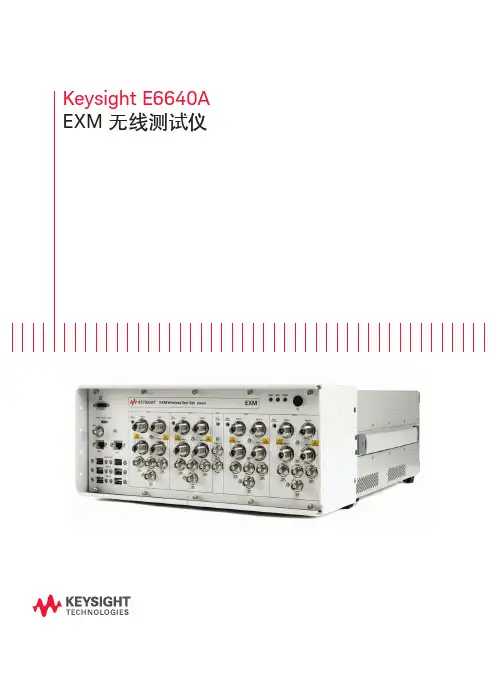
Keysight E6640A EXM 无线测试仪目录从容应对当前挑战,轻松满足未来需求 (2)根据您的生产需求进行扩展. (3)加速从新产品导入到全面量产的过程. (4)以更快的速度和更强的信心推出新产品系列. (5)为大批量制造创建灵活的系统. (7)测试场景 (10)推动芯片组获得更广泛的接受 (13)丰富经验支持 (13)产品导览 (14)相关文献 (16)从容应对当前挑战,轻松满足未来需求如今在无线行业中,智能手机和平板电脑相融合的技术数量令人难以置信。
支持蜂窝和无线连通性的多天线、多制式终端正在快速发展,满足最终用户对快速数据吞吐量、通用存取和即时共享的需要。
这给正在开发和生产最新的芯片组和用户设备(UE)的制造商带来重大挑战。
成功的制造商需要使用适当的工具,以便满足日渐严格的目标和紧凑日程。
制造商能够访问最好的资源,有助于应对技术、业务和运营风险,实行谨慎的风险管理可确保成功。
当这些风险因素得到控制时,企业就能实现几个关键目标:– 快速启动试生产– 实现并优化全面量产过程– 最大限度地降低总体测试成本– 满足预算要求– 降低损耗当前,多制式、多频段终端给制造商带来了巨大的测量挑战——找到效率更高而且效果更好的测试方法是成功的关键。
在此情况下,Keysight E6640A EXM 无线测试仪沿袭了之前测试仪中的非信令和排序功能。
根据您的生产需求进行扩展EXM 是基于 PXI 标准的平台,它的体系结构可以支持并行测试功能,并提供极高的可扩展性。
EXM 测试仪获得出色灵活性的关键是其功能丰富的发射/接收模块(TRX )。
您可以自由选择一个 TRX 模块并在今后添加多达三个 TRX 模块,您也可以升级 TRX 的频率或分析带宽,这样您能够经济有效地满足当前的生产要求,在今后生产需求扩张时保护您的投资。
2-TRX3-TRX4-TRX图 1. EXM 平台能够逐步扩大您的生产能力TRX 与 TRX 之间以及 RFIO 之间的高隔离度满足了用户对测试站支持密集度不断增加的天线和器件的需要。
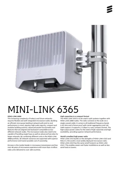
MINI-LINK 6365MINI-LINK 6000The increasing complexity of today’s and future networks requires flexible and well-integrated microwave nodes. Building an efficient microwave backhaul network with end-to-end performance in mind, requires high node capacity, compact and modular building practice, advanced packet functionality and features that are aligned and backward-compatible across different network nodes. The microwave nodes also need to be capable of handling single hops as well as advanced hub sites for larger networks. By combining different units in the MINI-LINK 6000 portfolio, all network scenarios are supported with superior performance and lowest possible cost of ownership.Ericsson is the market leader in microwave transmission and has over 40 years of microwave experience with more than 4 million radio units delivered to over 180 countries. High capacities in a compact formatThe MINI LINK 6365 is to be used in split systems together with MINI-LINK 6000 nodes. The radio connects to the node via a single coaxial cable. It comes in all traditional frequency bands 6-42 GHz and is future proof with carrier aggregation and 16k QAM support. It supports 2.5 Gbps in a very compact format. The high output power caters for the need of high capacities and high availability, providing superior network performance.World’s smallest high power radioMINI-LINK 6365 builds on the strengths of MINI-LINK 6363 and RAU2 X, the world´s most widely deployed microwave radio. MINI-LINK 6365 has the same small footprint as MINI-LINK 6363. This enables easier and faster installations as well as less wind load on towers.Ericsson ABSE-417 56 Göteborg, Sweden 287 01-FGC 101 3676 Rev B© Ericsson AB 2020Carrier aggregation – 2x 112 MHz and 2.5 GbpsMINI-LINK 6365 is a 1T1R radio supporting carrier aggregation. It can transmit two channels, up to 2x 112 MHz, in the same polarization,doubling the capacity vs MINI-LINK 6363. The channels can be adjacent or non-adjacent, for maximum utilization of available spectrum. 2x 112 MHz carrier aggregation provides a capacity of 2.5 Gbps, to support the ever-growing need for higher capacities. Carrier aggregation is available as a SW license, making it possible to double the capacity without changing the hardware.Highest modulation scheme – 16k QAMThe radio supports the highest modulation scheme in the market 16k QAM, increasing capacity by 15% vs 4k QAM and 25% vs 2k QAM.Superior system gainMINI-LINK 6365, in combination with MINI-LINK 6000 nodes, has the highest system gain in the split mount market, maintained also for higher modulations. The high system gain is crucial to enable the use of the high modulations and carrier aggregation. A high system gain means more capacity, higher availability and smaller antennas. High output power is available as a SW license, which makes it possible to step up in modulation and capacity when needed.Modular antennas and flat panel antennasMINI-LINK 6365 uses the same antenna portfolio as MINI-LINK 6363. The 0.3-1.8 m reflector antennas are modular, making them upgradeable from single to dual polarization without the need for realignment. This is done by replacing the interface only. With high focus on visual appearance and minimized size, Ericsson has created the world's smallest outdoor unit (radio+antenna) in traditional bands with a range of flat panel antennas. Since antenna performance is key to secure network performance, the flat panel antennas are guaranteed to be ETSI class 3 compliant and typically close to ETSI class 4 compliance.Scalable multi-carrier solutions, with hardware protectionA scalable upgrade path from single to multi-carrier is supported:1+0 → 2+0 → 4+0 → 8+0. Investments can be taken as the need for more capacity arises, following a pay as you grow approach. With MINI-LINK 6365, a single type of radio be can be used throughout the network. This simplifies network rollout and reduces operation costs. Transceivers in separate housings also gives better hardware protection and ensures no downtime during replacement of faulty hardware.Backward compatibilityMINI-LINK 6365 is hop compatible with MINI-LINK 6363 and MINI-LINK RAU2 X, in single carrier mode. If a radio unit needs to be upgraded, the antenna and radio cable can be reused.Ingress protectionThe radio unit can be installed in very harsh environments as it fulfills IP66 protection against dust and water.ATEX certifiedWith ATEX certification MINI-LINK 6365 can be used in potentially explosive atmospheres (Zone 2).Technical Specification MINI-LINK 6365RADIO LINKCapacity: 2.5 GbpsChannel: 7 – 112 MHzCarrier aggregation: 2x 28 – 2x 112 MHzModulation:4 QAM – 16k QAMTX power: -10 to +30 dBmFREQUENCIES 6 – 42 GHzWEIGHT 2.5 kg / 5.5 lbsDIMENSIONS (H × W × D) 179 × 197 × 79 mm (2.8 l) 7.0 × 7.8 × 3.1 in (170 in 3)POWER SUPPLY +57 VDCPOWER CONSUMPTION 24 WREFLECTOR ANTENNAS 0.2 – 3.7 m / 9 in – 12 ft HP and HPX SHP and SHPXFLAT PANEL ANTENNAS 0.1 m SHP28 – 42 GHz, 30 – 34 dBiINTEGRATEDCONFIGURATIONS 1+0, 1+1, 2+0, 4+0 and 8+0INTERFACES Coaxial (modem)Waveguide (antenna) Alignment portSTANDARDS AND RECOMMENDATIONS ETSI, ECC, FCC, IC, IEC, ITU, ATEXENVIRONMENTAL SPECIFICATIONS -45 to +60 °C / -49 to +140 °F IP66NODES MINI-LINK 6000NETWORK MANAGEMENTServiceOn Element Manager IP Transport NMSEricsson Network Manager。
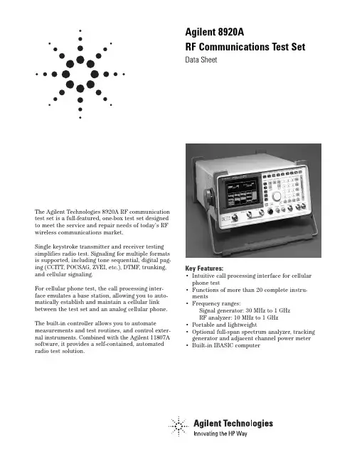
The Agilent Technologies 8920A RF communication test set is a full-featured, one-box test set designed to meet the service and repair needs of today’s RF wireless communications market.Single keystroke transmitter and receiver testing simplifies radio test. Signaling for multiple formats is supported, including tone sequential, digital pag-ing (CCITT, POCSAG, ZVEI, etc.), DTMF, trunking, and cellular signaling.For cellular phone test, the call processing inter-face emulates a base station, allowing you to auto-matically establish and maintain a cellular link between the test set and an analog cellular phone. The built-in controller allows you to automate measurements and test routines, and control exter-nal instruments. Combined with the Agilent 11807A software, it provides a self-contained, automated radio test solution.Key Features:•Intuitive call processing interface for cellular phone test•Functions of more than 20 complete instru-ments•Frequency ranges:Signal generator: 30 MHz to 1 GHzRF analyzer: 10 MHz to 1 GHz•Portable and lightweight•Optional full-span spectrum analyzer, tracking generator and adjacent channel power meter •Built-in IBASIC computerAgilent 8920ARF Communications Test SetData SheetAgilent 8920A RF Communications Test Set SpecificationsSpecifications describe the instrument’s warranted performance and are valid over the entire operating/environmental range unless otherwise noted.Supplemental Characteristics are intended to provide additional information useful in applying the instrument by giving typical, but non-warranted performance parameters. These characteristics are shown in italics or labeled as “typical,” “usable to,” or “nominal.”Signal Generator SpecificationsRF FrequencyFrequency Range:Standard: 30 MHz to 1 GHzOption 055:250 kHz to 1 GHzAccuracy and Stability:Same as reference oscillator ±0.015 Hz Reference Oscillator SpecificationsTCXO(Agilent 8920A standard)Temperature:1 ppm (0 to +55 °C)Aging:<2 ppm/yearWarm-Up time:<30 sec. to be ±2 ppm of final freq. Supplemental CharacteristicsSwitching Speed: <150 ms to within 100 Hz of the carrier frequencyMinimum Resolution:1 HzOutputRF IN/OUT ConnectorLevel Accuracy:±1.8 db (level ≥–127 dBm),Typically ±1.0 dB for all levelsLevel RangeStandard:Level Range:–137 to –20.5 dBm into 50 ΩReverse Power:60 watts continuous,100 watts for 10 seconds/minuteWith Option 007:Level Range:–137 to –6.5 dBm into 50 ΩReverse Power:2.4 watts continuous,4 watts for 10 seconds/minuteWith Option 008:Level Range:–137 to –10.5 dBm into 50 ΩReverse Power:6 watts continuous,10 watts for 10 seconds/minuteWith Option 016:Level Range:–137 to –22.5 dBm into 50 ΩReverse Power:100 watts continuous,125 watts for 10 seconds/minute Option 055:Level Range:–137 to –19 dBm into 50 ΩReverse Power:60 watts continuous,100 watts for 10 seconds/minuteWith Option 007:Level Range:–137 to –5 dBm into 50 ΩReverse Power:2.4 watts continuous,4 watts for 10 seconds/minuteWith Option 008:Level Range:–137 to –9 dBm into 50 ΩReverse Power:6 watts continuous,10 watts for 10 seconds/minuteWith Option 016:Level Range:–137 to –21 dBm into 50 ΩReverse Power:100 watts continuous,125 watts for 10 seconds/minuteDUPLEX OUT ConnectorStandard:Level Accuracy:±1.5 dB, typically ±1.0 dB for all levelsLevel Range:–127 to +5 dBm into 50 ΩReverse Power:200 mW maxOption 055:Level Range:–127 to +7 dBm into 50 ΩSWR:RF In/Out:<1.5:1Duplex Out:<2.0:1 (level <–4 dBm)Supplemental CharacteristicsMinimum Resolution:0.1 dBSpectral PuritySpurious Signals:For specified output levels at DUPLEX OUT port or specified output level at RF IN/OUT port.Option DUPLEX OUT RF IN/OUT Standard≤–2.5 dBm≤–26.5 dBm007≤–2.5 dBm≤–12.5 dBm007 with Opt. 055≤–1.0 dBm≤–11.0 dBm008≤–2.5 dBm≤–16.5 dBm008 with Opt. 055≤–1.0 dBm≤–15.0 dBm016≤–2.5 dBm≤–28.5 dBm016 with Opt. 055≤–1.0 dBm≤–27.0 dBm055≤–1.0 dBm≤–25.0 dBmHarmonics:<–30 dBcNon-Harmonic Spurious:<–60 dBc (at >5 kHz from carrier) Residual FM (rms, CCITT):Frequency Range8920A Standard8920A Opt. 050 250 kHz ≤f c<249 MHz<20 Hz<7 Hz249 MHz ≤f c<501 MHz<10 Hz<4 Hz501 MHz ≤f c≤1000 MHz<20 Hz<7 Hz2SSB Phase Noise: (For >20 kHz offsets at 1 GHz)8920A <–110 dBc/Hz8920A Opt. 050 <–116 dBc/HzFMFM Deviation Maximum (For rates >25 Hz)Standard and Options 007, 008, 016:100 kHz for f c from 30 MHz to <249 MHz50 kHz for f c from 249 MHz to <501 MHz100 kHz for f c from 501 MHz to 1000 MHzOption 055:100 kHz for f c from 0.25 MHz to <249 MHz50 kHz for f c from 249 MHz to <501 MHz100 kHz for f c from 501 MHz to 1000 MHzFM Rate (1 kHz reference)Internal:DC to 25 kHz (1 dB BW)External:AC Coupled: 20 Hz to 75 kHz (typically 3 dB BW)DC Coupled: DC to 75 kHz (typically 3 dB BW)FM Accuracy:(1 kHz rate)≤10 kHz dev: ±7.5% (3.5%*) of setting ±50 Hz>10 kHz dev: ±7.5% (3.5%*) of setting ±500 HzFM Distortion:(THD + Noise, in a 0.3 to 3 kHz BW)<1% (0.5 %*) at > 4 kHz deviation and 1 kHz rateCenter Frequency Accuracy in DC FM Mode:(External source impedance <1 kΩ) ±500 Hz(after DC FM zero), typically ±50 HzSupplemental CharacteristicsExternal Modulation Input Impedance: 600 Ωnominal Resolution: 50 Hz for <10 kHz deviation, 500 Hz for >10 kHz deviationAMStandard:Frequency Range:30 MHz to 1 GHzAM Depth:0 to 90% (usable to 99%) for DUPLEX OUT level ≤–2.5 dBm or RF IN/OUT level ≤–26.5dBm; 0 to 70% (usable to 90%*)Option 055:Frequency Range:1.5 MHz to 1 GHz (usable to 250kHz)AM Depth:0 to 90% (usable to 99%) for DUPLEX OUT level ≤+1 dBm or RF IN/OUT level ≤–27dBm; 0 to 70% (usable to 90%*)AM Rate:20 Hz to 25 kHz (3 dB BW)AM Accuracy:(1 kHz rate)≤10% AM: ±5% of setting ±1.0% AM>10% AM: ±5% of setting ±1.5% AMAM Distortion:(THD+Noise 0.3 to 3 kHz BW)<2% at 1 kHz rate, <30% AM<3% at 1 kHz rate, ≤90% AM External Mod. Input Impedance:600 ΩnominalResidual AM: <0.1% in a 50 Hz to 15 kHz BWResolution: 0.05% AM from 0 to 10% AM, 0.5% AM from 10 to 100% AMAudio Source Specifications(Applicable to both internal sources)FrequencyRange:dc to 25 kHzAccuracy:0.025% of settingSupplemental CharacteristicsMinimum Resolution: 0.1 HzOutput LevelRange:0.1 mV to 4 VrmsMaximum Output Current:20 mA peakOutput Impedance:<1 Ω(1 kHz)Accuracy:±2% of setting plus resolutionResidual Distortion:0.125%(THD plus noise, for amplitudes >200 mVrms), for tones 20 Hz to 25 kHz measured in an 80 kHz BWSupplemental CharacteristicsResolution:Level <0.01V: ±50 µVLevel <0.1V: ±0.5 mVLevel <1V: ±5 mVLevel <10V: ±50 mVOffset in DC Coupled Mode: <50 mVRF Analyzer MeasurementsRF Frequency MeasurementsMeasurement Range:Standard:30 MHz to 1 GHzOption 055:400 kHz to 1 GHzLevel Range:RF In/Out:Standard:1 mW to 60 W continuous 100 W for10 seconds/minuteOption 007:40 mW to 6 W continuous 4 W for10 seconds/minuteOption 008:0.1 mW to 6 W continuous 10 W for10 seconds/minuteOption 016:1.6 mW to 100 W continuous 150 W for10 seconds/minuteANT IN:–36 dBm to +20 dBmAccuracy:±1 Hz plus timebase accuracy3Minimum Frequency Resolution: 1 HzRF Power MeasurementsFrequency Range:Standard:30 MHz to 1 GHzOption 055:400 kHz to 1 GHzSWR:<1.5:1 for standard and all optionsRF IN/OUT Measurement Range:Standard:1 mW to 60 W continuous or to 100 W for10 sec/minuteAccuracy:±10% of reading ±1 mWOption 007:40 µW to 2.4 W continuous 4 W for10 seconds/minuteAccuracy:±10% of reading ±40 µWOption 008:0.1 mW to 6 W continuous 10 W for10 seconds/minuteAccuracy:±10% of reading ±0.1 mWOption 016:1.6 mW to 100 W continuous 125 W for10 seconds/minuteAccuracy:±10% of reading ±1 mWSupplemental CharacteristicsResolution: P >10 W: 10 mW, P <10 W: 1 mW; P <100 mW: 0.1 mW, P <10 mW: 0.01 mWFM MeasurementFrequency Range:Standard:10 MHz to 1 GHzOption 055:5 MHz to 1 GHz (Usable to 400 kHz) Deviation:20 Hz to 75 kHzSensitivity:2 µV (15 kHz IF BW, high sensitivity mode, 0.3 to 3 kHz BW, 12 SINAD, fc >10 MHz) Typically:<1 µVAccuracy:±4% of reading plus residual FM and noise contribution (20 Hz to 25 kHz rates, deviation ≤25kHz)Bandwidth (3 dB):2 Hz to 70 kHz (DC FM measurements also available)Input Level Range for Specified Accuracy:Standard:–50 dBm to +14 dBm at ANT IN –18 to +50 dBm at RF IN/OUT (0.16 mW to 100 W*)Option 007:–32 to +36 dBm at RF IN/OUT (0.63 µW to 4 W*) Option 008:–28 to +40 dBm at RF IN/OUT (1.58 µW to 10 W*) Option 016: –16 to +51 dBm at RF IN/OUT (0.25 µW to 125 W*) *Note: The accuracy shown is for the complete range of power. The maximum power levels shown are only usable for 10sec/min.Residual FM and Noise:20 Hz (0.3 to 3 kHz, rms), <7Hz (with Agilent 8920A Opt 050)Resolution: 1 Hz, f <10 kHz; 10 Hz, f ≥10 kHzAM MeasurementFrequency Range:10 MHz to 1 GHz (usable to 400 kHz) Depth:0 to 95%Accuracy:±5% of reading ±1.5% AM (50 Hz to 10 kHz rates, mod-ulation ≤80%)THD + Noise:<2% rms for modulation ≤80% AM (at 1 kHz rate in a 0.3 to 3 kHz BW)Input Level Range for Specified Accuracy:Standard:–50 dBm to +14 dBm at ANT IN –18 to +50 dBm at RF IN/OUT (0.16 mW to 100 W*)Option 007:–32 to +36 dBm at RF IN/OUT (0.63 µW to 4 W*) Option 008:–28 to +40 dBm at RF IN/OUT (1.58 µW to 10 W*) Option 016:–16 to +51 dBm at RF IN/OUT (0.25 µW to 125 W*) *Note: The accuracy shown is for the complete range of power. The maximum power levels shown are only usable for 10 sec/min. Residual AM:<0.2% in a 0.3 to 3 kHz bwSupplemental CharacteristicsResolution: 0.1%SSB MeasurementFrequency Range:Standard:10 MHz to 1 GHzOption 055:400 kHz to 1 GHzBandwidth (3 dB):20 Hz to 70 HzDistortion and Noise:<3% (at 1 kHz rate in a 0.3 to 3 kHz BW)AF Analyzer SpecificationsFrequency MeasurementMeasurement Range:20 Hz to 400 kHzAccuracy:±0.02% plus resolution plus timebase accuracy External Input:20 mV to 30 VrmsSupplemental CharacteristicsResolution:0.01 Hz, f <10 kHz; 0.1 Hz, f <100 kHz; and 1 Hz forf ≥100 kHzAC Voltage MeasurementMeasurement Range:0 to 30 VrmsAccuracy:±3% of reading (20 Hz to 15 kHz, inputs >1 mV) Residual Noise:150 µV (15 kHz bandwidth)43 dB Bandwidth: Typically 2 Hz to 100 kHzNominal Input Impedance: Switchable between1 MW in parallel with 95 pF or 600 ΩfloatingMinimum Resolution:4 digits for inputs ≥100 mV; three digits for inputs <100 mVDC Voltage MeasurementVoltage Range:100 mV to 42 VAccuracy:±1% of reading plus DC offsetDC Offset:±45 mVSupplemental CharacteristicsResolution:1 mVDistortion MeasurementFundamental Frequency:1 kHz ±5 HzOption 019 Frequency Range:0.3 to 10 kHz ±5%Input Level Range:30 mV to 30 VrmsDisplay Range:0.1% to 100%Accuracy:±1 dB (0.5 to 100% distortion) for tones from 300 to 1500 Hz measured with the 15 kHz LPF±1.5 dB (1.5 to 100% distortion) for tones from 300 Hz to 10 kHz measured with the >99 kHz LPF)Residual THD + Noise:–60 dBc or 150 µV whichever is greater, for tones from 300 to 1500 Hz measured with the 15 kHz LPF–57 dBc or 450 µV, whichever is greater, for tones from 300 Hz to 10 kHz measured with >99 kHz LPF)Supplemental CharacteristicsResolution: 0.1% distortionSINAD MeasurementFundamental Frequency:1 kHz ±5 HzOption 019 Frequency Range:0.3 to 10 kHz ±5%Input Level Range:30 mV to 30 VrmsDisplay Range:0 to 60 dBAccuracy:±1 dB (0 to 46 dB SINAD) for tones from 300 to 1500 Hz measured with the 15 kHz LPF±1.5 dB (0 to 36 dB SINAD) for tones from 300 Hz to 10 kHz meas-ured with the >99 kHz LPFResidual THD + Noise:–60 dBc or 150 mV, whichever is greater, for tones from 300 to 1500 Hz measured with the 15 kHz LPF–57 dBc or 450 mV, whichever is greater, for tones from 300 Hz to 10 kHz measured with >99 kHz LPF Resolution: 0.01 dBAudio FiltersStandard:<20 Hz HPF, 50 Hz HPF, 300 Hz HPF 300 Hz LPF, 3 kHz LPF, 15 kHz LPF, >99 kHz LPF, and 750 µsec de-emphasisFixed Notch:1 kHz, (Agilent 8920A standard)Variable Notch:300 Hz to 10 kHz (Option 019)Optional:C-Message, CCITT, 400 Hz HPF, 4 kHz BPF, 6 kHz BPF (see options)Audio Detectors: RMS, RMSxSQRT2, Pk+, Pk–, Pk+hold, Pk–hold, Pk±/2, Pk±/2 hold, Pk±max and Pk±max hold Oscilloscope SpecificationsFrequency Range:2 Hz to 50 kHz (3 dB BW)Scale/Division:10 mV to 10 VAmplitude Accuracy:±1.5% of reading ±0.1 division(20 Hz to 10 kHz)Time/Division:1 µsec to 200 msecSupplemental Characteristics3 dB Bandwidth: Typically >100 kHzInternal DC Offset: ≤0.1 div (≥50 µV/div sensitivity)Input and Output SpecificationsDigital Interface PortRS-232 port:2 wayConnector: RJ-11connector (6 pins; 2 addressable serial ports with single connector; Agilent 8920A rear panel)Baud Rates:300/600/1200/2400/4800/9600/19200Reference In PortConnector:BNC female (8920A rear panel)Input frequency:1/2/5/10 MHzInput Level Range:>0.15 VrmsReference Out PortConnector:BNC female (8920A rear panel)Output Frequency:10 MHzOutput Level: >0.5 VrmsStandard User Memory, RAMApproximately 1 Mbyte of RAM is available for nonvolatilesave/recall of settings. This typically will allow you to save >1000 sets of instrument settings; depending on the type of information saved.5Option SpecificationsOption 001: High Stability TimebaseOCXO: (Oven controlled crystal oscillator)Temperature:0.05 ppm (0 to +55 °C)Aging:<0.5 pm/year (<1 ppm in first year)Warm-up Time:<15 minutes to be within ±0.1 ppm of finalfrequencySupplemental CharacteristicsRear Panel BNC Connectors:Input Frequency: 1, 2, 5, and 10 MHzInput Level: >0.15 VrmsOutput Frequency: 10 MHzOutput Level: >0.5 VrmsOption 004: Tone/Digital SignallingCapability for generating and analyzing the formats listed here: CDCSS, DTMF, 1-TONE, 2-TONE, 5/6 TONE SEQUENTIAL, RPC1, POCSAG, EIA, CCITT, CCIR, ZVEI, DZVEI, GOLAY, EEA, NMT-450, NMT-900, LTR, AMPS/EAMPS/NAMPS, TACS/ETACS,JTACS/NTACS, EDACS, and MPT 1327.A General Purpose function generator with the following wave forms included:Sine, square, triangle, ramp, Gaussian white noise, uniform white noiseFrequency Range/Level:Same as audio sourceOption 007 and Low-Level RF Power MeasurementsOption 007 removes a 14 dB attenuator at the RF IN/OUT port allowing lower-level, higher sensitivity measurements. This option reduces the maximum continuous input power of the Agilent 8920A from 60 watts to 2.4 watts. Specifications for Option 007 are included in the appropriate sections of: Signal Generator out-put, RF Analyzer, Frequency and Power Measurement Ranges, FM and AM Measurement Input Level Ranges.Option 008 Cellular Mobile RF Power Measurement RangeOption 008 removes 10 dB attenuation at the RF IN/OUT port allowing lower-level, higher sensitivity measurements specifically for the range of cellular telephones testing. This option reduces the maximum continuous input power of the 8920A from 60 watts to 6 watts. Specifications for Option 008 are included in the appro-priate sections of: Signal generator output, RF analyzer, frequency and power measurement ranges, FM and AM measurement input level ranges.Option 010: 400 Hz High Pass FilterOption 011: CCITT Weighting FilterOption 012: 4 kHz Bandpass Filter Option 013: C-Message Weighted FilterOption 014: 6 kHz Bandpass FilterOption 016 High-Level RF Power Measurements Option 016 for the 8920A supports high-power transmitter meas-urement applications. Option 016 can only be ordered on a new instrument at the time of purchase. Option 016 can only be installed at the factory.Option 019: Variable Notch FilterFrequency Range:300 Hz to 10 kHzNotch Depth:>60 dBNotch Width:Typically ±5%Option 020: Radio Interface CardThe Option 020 for the 8920A is a built-in radio interface card for automating module and radio board test. It contains 16 parallel data lines, two interrupts, and brings the audio in/out lines and a relay closure out from the MIC/ACC connector on the front panel. These are controlled by the 8920A BASIC control language. Line Levels:5 volts or 12 voltsOption 050: Improved Residual FM Performance Includes high stability timebase (Option 001), improved residual FM performance.Option 102: Spectrum Analyzer with Tracking Generator and ACPFrequency Range:10 MHz to 1 GHzFrequency Span/Resolution Bandwidth:(coupled)Span Bandwidth<50 kHz300 Hz<200 kHz 1 kHz<1.5 MHz 3 kHz<18 MHz30 kHz>18 MHz300 kHz, plus full span capabilityDisplay:Log with 1, 2, and 10 dB/divDisplay Range:80 dBReference Level Range:+50 to –50 dBmResidual Responses:<–70 dBm (no input signal, 0 dB attenuation)Image Rejection:>50 dBmSupplemental CharacteristicsNon-Harmonic Spurious Responses: >70 dB down (for input sig-nals ≤–30 dBm)6Level Accuracy: ±2.5 dBDisplayed Average Noise Level: <–114 dBm for <50 kHz spans Log Scale Linearity: ±2 dB (for input levels ≤–30 dBm and/or 60 dB rangeTracking Generator (In Option 102)Frequency Range:30 MHz to 1 GHzFrequency Offset:Frequency span endpoints ±frequency offset cannot be <30 MHz or ≥1 GHzOutput Level Range:Same as signal generatorSweep Modes:Normal and invertedAdjacent Channel Power (In Option 102) Relative Measurements:Level Range:Antenna IN:–40 dBm to +20 dBmRF/Input:0.16 mW (–8 dBm) to 60 W (47.8 dBm)continuous; or up to 100 mW (50 dBm) for 10 sec/min Dynamic Range:Typical values for channel offsetsChannel Offset Res. BW Dyn. Range12.5 kHz8.5 kHz–65 dBc20 kHz14 kHz–68 dBc25 kHz16 kHz–68 dBc30 kHz16 kHz–68 dBc60 kHz30 kHz–65 dBcRelative Accuracy:±2 dBAbsolute Level Measurements:Level:(Results of absolute power in watts or dBm are met by adding the ACP ratio from the SA to the carrier power from the input section RF power detector).Level Range:Antenna:N/ARF/Input:1 mW (0 dBm) to 60 W (47.8 dBm) continuous; or up to 100 W (50 dBm) for 10 sec/minDynamic Range:Typical values for channel offsetsChannel Offset Res. BW Dyn. Range12.5 kHz 8.5 kHz–65 dBc20 kHz 14 kHz–68 dBc25 kHz 16 kHz–68 dBc30 kHz 16 kHz–68 dBc60 kHz 30 kHz–65 dBcAbsolute Accuracy:RF power measurement accuracy found in the RF Analyzer section and ACP relative accuracy of ±2 dB Option 103: DC Current Sensing and I/O:GPIB/RS-232/Parallel (Centronics)DC Current MeterMeasurement Range:0 to 10 A (usable to 20 A)Accuracy:The greater of ±10% of reading after zeroing or 30 mA (levels >100 mA)Remote ProgrammingGPIB:Agilent’s implementation of IEEE Standard 488.2 Functions Implemented:SH1, AH1, T6, L4, SR1, RL1, LE0, TE0, PP0, DC1, DT1, C4, C11, E2RS-232:Two serial ports through RJ-11 connector used for serial data in and outBaud Rates:150, 300, 600, 1200, 2400, 4800, 9600 and 19200 Hz Parallel (Centronics) Connector: A standard 25-pin, sub-min D female connector with right-angle adapter is includedNote: Retrofittable only for 8920A units with serial prefix numbers of 3501 or greaterGeneral Specifications8920A Dimensions:H ϫW ϫD in inches and (mm): 7.5 H ϫ13 W ϫ19 D (188 H ϫ330 W ϫ456 D)8920A Weight:(fully optioned) 37 lbs. (16.8 kgs)8920A Power:AC: 100 V to 240 V, 48 to 440 Hz, nominally 80 wattsDC: 11 to 28 V, nominally 120 watts8920D Power:AC: 100 V to 240 V ±10%, 48 Hz to 440 Hz, nominally 100 watts CRT Size:7 ϫ10 cmOperating Temperature:0 to +55 °CStorage Temperature:–55 to +75 °CCalibration Interval:Two yearsSupplemental CharacteristicsLeakage: At signal generator output frequency and level <–40 dBm, typical leakage is <0.5 µV induced in a resonant dipole antenna one inch from any surface except the rear panel. Spurious leakage levels are typically <1 µV in a resonant dipole antenna.7H i g h S t a b i l i t y T i m e b a s eS i g n a l i n gL o w -P o w e r M e a s u r e m e n tC e l l u l a r M S R F P o w e r R a n g e400 H z H i g h -P a s s F i l t e rC C I T T W e i g h t i n g F i l t e r4 k H z B a n d p a s s F i l t e rC -M e s s a g e W e i g h t i n g F i l t e r6 k H z B a n d p a s s F i l t e rV a r i a b l e F r e q u e n c y F i l t e rM e c h a n i c a l A t t e n u a t o rS p e c r u m A n a l y ./T r a c k i n g G e nG P I B /R S -232 P a r a l l e l11807A R a d i o T e s t S o f t w a r e (O p t i o n s )Automated FM Radio Test 3O O O O O O 001Automated φm Radio Test 3O OOOO 002Automated AM Radio Test OO003Testing Communications Bandwidths <30 MHz XCordless Phone Test 3OOXOFrequency Scanning O Cable Fault Location 2X O Field Strength Measurement XO 100Intermodulation Prod. Cal.O Save/Recall Procedure OLTR Trunked Radio Test 3(Includes FM radio tests)O X X O O O 010EDACS Trunked Radio Test 3(Includes FM radio tests)O X O O O O 011MPT 1327 Trunked Radio Test 3O X OO OO 012AMPS/EAMPS/NAMPS O X OO O O 004TACS/ETACS O X O OO O 005NMT 450/900O X O OO O 006JTACS/NTACSOXOOO007Configuration InformationX = Required Option O = Recommended Option 8920A Options00100400710081010011012013014019055102103M e a s u r i n g C a p a b i l i t yT r u n k e d R a d i oC e l l u l a r P h o n e T e s t1.Options 007 and 008 reduce the maximum input power of the 8920A from 60 watts to2.4 and 6 watts respectively. Option 008 is recommended for applications where the 8920A is used for cellular phone test only.2.Requires an external power divider and 50 ohm load to make measurement.3.Testing frequencies below 30 MHz will require ordering Option 055 (400 kHz to 1 GHz).By internet, phone, or fax, get assistance with all your test and measurement needs.Online Assistance/find/assistProduct specifications and descriptions in this document subject to change without notice.Copyright © 1994, 2000 Agilent Technologies Printed in U.S.A. 10/005968-5385EFor more information, visit our website at:/find/8920support/。
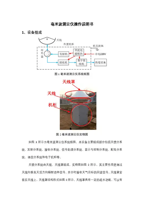
毫米波测云仪操作说明书1、设备组成图1毫米波测云仪系统框图图2毫米波测云仪实物图如图1所示为毫米波测云仪系统框图,本设备主要组成部分包括天馈分系统、发射分系统、接收分系统、信号处理分系统、显示与控制分系统、配电分系统、通信分系统和电子机柜等。
天馈分系统由天线、天线罩组成,实物图如图2所示。
其主要作用是通过天线向垂直天顶方向辐射功率信号,并分时接收天气目标的回波信号。
天线罩安装在天线上,天线罩结构形式如图2所示。
天线罩具有一定的疏水功能,可以有效减少雨滴雪花附着到天线表面,降低雨雪天气过程对设备的影响。
图3发射机和接收机分系统实物图发射分系统实物图如图3所示,其主要作用是将频综产生的激励信号功率放大,以达到系统所要求的发射功率,并经环行器送往天线,由天线将射频功率信号辐射至外部空间。
接收分系统实物图如图3所示,其主要作用是将天线接收到的射频信号经过低噪放、混频、滤波、放大,输出60MHz 中频信号至数字接收机。
数字接收机实物图如图4所示,其主要作用是将60MHz 中频信号数字化,完成数字下变频、脉冲压缩、相干积累、FFT 和非相干积累等一系列信号处理流程,生成I/Q 信息、功率谱数据等原始数据,并将原始数据通过光纤传输给终端设备。
电源模块实物图如图4所示,其主要作用是将220V 市电转化为适合各个分系统工作的直流电源,并提供一定用电保护功能。
发射机至天线接收机图4电源模块和数字接收机分系统实物图图5电子机柜实物图如图5所示为电子机柜实物图,两个柜门位于电子机柜两侧,风机排风口和外接电缆接口上下排列于机柜正面。
其中发射分系统、接收分系统、数字接收机和电源模块全部位于电子机柜内部。
电子机柜内部装有风机可以起到风冷作用,同时具备防风沙、防雨水的作用。
电子机柜为内部电子模块提供相对稳定的工作环境,提高系统运行稳定性。
数字接收机图6终端设备实物图如图6所示为终端设备实物图,终端设备包括带有光电转换模块的交换机、终端工控机和显示器。
SAFETY, ENVIRONMENT AL, AND REGULA TORY INFORMA TIONUSRP-2930/293220 MHz Bandwidth, 1 Gigabit Ethernet, GPS-Disciplined OCXO, USRP Software Defined Radio DeviceRead this document and the documents listed in the additional resources section about installation, configuration, and operation of this equipment before you install, configure, operate, or maintain this product. Users are required to familiarize themselves with installation and wiring instructions in addition to requirements of all applicable codes, laws, and standards.Regulatory IconsNotice Take precautions to avoid data loss, loss of signal integrity, degradation of performance, or damage to the model.Caution Take precautions to avoid injury. Consult the model documentation for cautionary statements when you see this icon printed on the model.ESD Sensitive Take precautions to avoid damaging the model with electrostatic discharge.SafetyCaution Observe all instructions and cautions in the user documentation. Using the model in a manner not specified can damage the model andcompromise the built-in safety protection. Return damaged models to NI for repair.Attention Suivez toutes les instructions et respectez toutes les mises en garde de la documentation utilisateur. L'utilisation d'un modèle de toute autrefaçon que celle spécifiée risque de l'endommager et de compromettre la protection de sécurité intégrée. Renvoyez les modèles endommagés à NI pour réparation.Caution The protection provided by the model can be impaired if it is used in a manner not described in the user documentation.Attention La protection apportée par le modèle risque d'être endommagée s'il est utilisé d'une autre façon que celle décrite dans la documentationutilisateur.Safety Compliance StandardsThis product is designed to meet the requirements of the following electrical equipment safety standards for measurement, control, and laboratory use:•IEC 61010-1, EN 61010-1•UL 61010-1, CSA C22.2 No. 61010-1Note For UL and other safety certifications, refer to the product label or the Product Certifications and Declarations section.Electromagnetic and Radio Equipment Compatibility GuidelinesThis product was designed to support an efficient use of the radio spectrum to avoid harmful interference. This product was tested and complies with the regulatory requirements and limits for electromagnetic compatibility (EMC) as stated in the product specifications. These requirements and limits are designed to provide reasonable protection against harmful interference when the product is operated in its intended operational electromagnetic environment.This product is intended for use in commercial and light-industrial locations. However, harmful interference may occur in some installations, when the product is connected to a peripheral device or test object, or if the product is used in residential areas. To minimize interference with radio and television reception and prevent unacceptable performance degradation, install and use this product in strict accordance with the instructions in the product documentation. Furthermore, any changes or modifications to the product not expressly approved by NI could void your authority to operate it under your local regulatory rules.Electromagnetic and Radio Performance NoticesRefer to the following notices for cables, accessories, and prevention measures necessary to ensure the specified electromagnetic and radio performance.Notice Operate this product only with shielded cables and accessories. The DC power input cables may be unshielded.Notice To ensure the specified electromagnetic and radio performance, the length of all I/O cables except those connected to the Ethernet and GPS antenna ports must be no longer than 3 m.Notice This product is not approved or licensed for transmission over the air using an antenna. As a result, operating this product with an antenna may violate local laws. This product is approved for signal reception using a GPS antenna in the appropriate port. Ensure that you are in compliance with all local laws before operating this product with an antenna other than a GPS receive antenna.Notice The performance of this product can be disrupted if subjected to Electrostatic Discharge (ESD) during operation. To prevent damage,industry-standard ESD prevention measures must be employed during installation, maintenance, and operation. Electromagnetic Compatibility StandardsThis product meets the requirements of the following EMC standards for electrical equipment for measurement, control, and laboratory use:•EN 61326-1 (IEC 61326-1): Class A emissions; Basic immunity•EN 55011 (CISPR 11): Group 1, Class A emissions•AS/NZS CISPR 11: Group 1, Class A emissions•FCC 47 CFR Part 15B: Class A emissions•ICES-003: Class A emissionsNote Group 1 equipment (per CISPR 11) is any industrial, scientific, or medical equipment that does not intentionally generate radio frequencyenergy for the treatment of material or inspection/analysis purposes.Note In the United States (per FCC 47 CFR), Class A equipment is intended for use in commercial, light-industrial, and heavy-industrial locations. InEurope, Canada, Australia and New Zealand (per CISPR 11) Class A equipment is intended for use only in non-residential locations.Note For EMC declarations, certifications, and additional information, refer to the Product Certifications and Declarations section.Radio Equipment Compatibility StandardsThis product meets the requirements of the following Radio Equipment standards:•ETSI EN 301 489-1: Common Technical Requirements for Radio Equipment•ETSI EN 301 489-19: Specific conditions for GNSS receivers operating in the RNSS band (ROGNSS) providing positioning, navigation, and timing data •ETSI EN 303 413: Satellite Earth Stations and Systems (SES); Global Navigation Satellite System (GNSS) receiversThis radio equipment is for use in accordance with the following parameters:Antenna 5 V GPS receiver antenna, part number 783480-01Software LabVIEW, LabVIEW NXG, LabVIEW Communications System Design Suite Frequency band(s)1,575.42 MHzNotice Every country has different laws governing the transmission and reception of radio signals. Users are solely responsible for using their USRP system in compliance with all applicable laws and regulations. Before you attempt to transmit and/or receive on any frequency, National Instruments recommends that you determine what licenses may be required and what restrictions may apply. National Instruments does not accept any responsibility for the user's use of our products. The user is solely responsible for complying with local laws and regulations.Environmental GuidelinesNotice This model is intended for use in indoor applications only.Environmental CharacteristicsTemperature and HumidityOperating Temperature0 °C to 45 °COperating Humidity10% to 90% relative humidity, noncondensingPollution Degree2Maximum altitude2,000 m (800 mbar) (at 25 °C ambient temperature)Shock and VibrationOperating shock30 g peak, half-sine, 11 ms pulseRandom VibrationOperating 5 Hz to 500 Hz, 0.3 g rmsNonoperating 5 Hz to 500 Hz, 2.4 g rmsEnvironmental ManagementNI is committed to designing and manufacturing products in an environmentally responsible manner. NI recognizes that eliminating certain hazardous substances from our products is beneficial to the environment and to NI customers.2| | USRP-2930/2932For additional environmental information, refer to the Commitment to the Environment web page at /environment. This page contains the environmental regulations and directives with which NI complies, as well as other environmental information not included in this document.Waste Electrical and Electronic Equipment (WEEE)EU Customers At the end of the product life cycle, all NI products must be disposed of according to local laws and regulations. For moreinformation about how to recycle NI products in your region, visit /environment/weee.电子信息产品污染控制管理办法(中国RoHS)中国客户National Instruments符合中国电子信息产品中限制使用某些有害物质指令(RoHS)。
无线电制作仪用户说明书V2.0仪表经过多次改进,能测量大电感,大电容;小电感,小电容;高频频率,低频频率;直流电压;高频交流电压。
仪器特点:能同时显示线圈的电阻分量,电感分量;能同时显示电源的直流分量和交流分量;电容,电感,频率的量程大。
仪器使用额定5V电源,电源杂波越小越好。
一、参数:大电感:900uH----------100H大电容:5nF--------------1F小电感:50nH------------2mH小电容:1pF--------------10nF高频频率:1MHz---------2GHz低频频率:2KHz---------12MHz直流电压:0V-------------15V(X1);0V---------------55V(X10)交流电压(有效值):0V-------------1.8V(X1);0V---------------18V(X10)二、使用方法:如下图所示:图中是仪表的正视图,各个按键的功能有图中的表格列出。
仪器的基本使用方法是接入5V电源,打开电源开关,中间的单刀三掷拨动开关选择测量电容,电感;频率;电压三类功能。
表格中每一行表示仪表的一类功能下,仪表各个按钮,端口的功能。
空白表示该按钮或端口和本行表示的功能无关。
因为仪器中间有两个按键,表格的中间用突出部分表示上面的按键。
一般在进入某功能时不要接入测试元件,因为进入功能时,仪器根据外部情况进行校正。
A.电感电容首先中间的功能选择开关拨到最右边。
测量大电感:中间扭子开关向左,左边拨动开关向左,元件接入大电容电感测量端子即可测量。
仪器显示电感分量和串联电阻分量。
测量大电容:中间扭子开关向右,左边拨动开关向左,元件接入大电容电感测量端子即可测量。
(测量端子左正有负;当仪器显示“R=Can’t Measure”不可接入电阻,因为此时电阻默认为无穷大)仪器显示电容分量和并联电阻分量。
测量小电感:中间扭子开关向左,左边拨动开关向右,元件接入小电容电感测量端子即可测量。
80GHz 雷达 (FMCW) 物位变送器用于含内部干扰件的狭窄罐体应用OPTIWAVE 7500 C操作手册© KROHNE 09/2018 - 4007101701 - MA OPTIWAVE 7500 R01 zh保留所有权。
未经KROHNE Messtechnik GmbH 公司事先书面授权,不得复制此文件及其任何部分。
如有更改,恕不通知。
2 09/2018 - 4007101701 - MA OPTIWAVE 7500 R01 zh版权所有 2018KROHNE Messtechnik GmbH - Ludwig-Krohne-Str. 5 - 47058 Duisburg (德国): 版本说明3 09/2018 - 4007101701 - MA OPTIWAVE 7500 R01 zh 1 安全须知61.1 软件历史 (6)1.2 用途 (6)1.3 认证 (7)1.4 电磁兼容性 (7)1.5 无线电批准证书 (8)1.5.1 欧盟 (EU) (8)1.5.2 美国 (10)1.5.3 加拿大 (11)1.6 来自制造厂家的安全须知 (13)1.6.1 版权及数据保护.............................................................131.6.2 免责条款...................................................................131.6.3 产品责任及质保.............................................................141.6.4 有关文档的信息.............................................................141.6.5 警告与符号使用 (15)1.7 操作者的安全须知........................................................152 设备描述162.1 供货范围 (16)2.2 仪表说明................................................................172.3 外观检查. (18)2.4 铭牌 (19)2.4.1 铭牌 (示例)..............................................................193 安装203.1 通用安装提示 (20)3.2 存储 (20)3.3 运输 (21)3.4 安装前要求 (21)3.5 压力和温度范围 (22)3.6 推荐的安装位置 (22)3.6.1 通用说明 (23)3.6.2 具有盘状和锥形底部的储罐 (24)3.7 安装限制 (24)3.7.1 通用说明 (25)3.7.2 过程连接 (26)3.7.3 LPR 仪表:对于在井坑和非导电材质罐体的安装建议 (29)3.8 如何旋转或移除显示模块(选件) (30)3.9 防护罩 (31)3.9.1 如何将防护罩连接至仪表上 (31)3.9.2 如何打开防护罩.............................................................334 电气连接344.1 安全须知 (34)4.2 电气安装:2线制,回路供电 (34)4.3 电流输出的电气连接 (38)内容4 09/2018 - 4007101701 - MA OPTIWAVE 7500 R01 zh4.3.1 非防爆仪表 (38)4.3.2 用于危险区域的仪表 (38)4.4 防护等级 (38)4.5 网络 (39)4.5.1 基本信息...................................................................394.5.2 点到点连接.. (39)4.5.3 多点网络...................................................................405 启动415.1 启动检查列表 (41)5.2 如何启动仪表 (41)5.3 操作概念 (41)5.4 数显屏幕 (42)5.4.1 显示屏布局 (42)5.4.2 键盘按钮 (43)5.5 通过PACTware ™远程通讯 (45)5.6 通过AMS ™设备管理器进行远程通讯........................................466 操作476.1 用户模式 (47)6.2 常规模式 (47)6.3 程序模式 (50)6.3.1 常规注意事项...............................................................506.3.2 仪表设置保护(访问级别)...................................................506.3.3 如何访问快速设置菜单.......................................................526.3.4 键盘功能...................................................................536.3.5 如何保存程序模式中更改的设置...............................................566.3.6 菜单一览...................................................................576.3.7 功能说明...................................................................626.4 程序模式下仪表配置的更多信息 (77)6.4.1 标准设置...................................................................776.4.2 空频谱记录.................................................................796.4.3 HART ® 网络设置............................................................826.4.4 距离测量...................................................................826.4.5 物位测量...................................................................846.4.6 如何设置仪表测量体积或质量.................................................856.4.7 如何在弯曲或锥形底部的储罐中进行正确测量...................................876.4.8 如何制作滤波器以去除雷达信号干扰...........................................876.5 状态消息和诊断数据......................................................887 服务947.1 周期性维护 (94)7.1.1 常规注意事项 (94)7.1.2 维护外壳盖的O 形圈 (94)7.1.3 如何清洁仪表的顶部表面 (95)7.2 服务保修 (95)7.3 备件可用性 (95)7.4 可提供的服务 (96)5 09/2018 - 4007101701 - MA OPTIWAVE 7500 R01 zh 7.5 仪器送返生产厂家........................................................967.5.1 基本信息. (96)7.5.2 送返仪器时附带的表格(可复印) (97)7.6 处理....................................................................978 技术数据988.1 测量原理 (98)8.2 技术数据 (100)8.3 最小供电电压 (105)8.4 测量精度 (106)8.5 最大操作压力指令 (110)8.6 尺寸和重量.............................................................1129 HART 接口1189.1 综述 (118)9.2 软件历史 (118)9.3 连接变量 (119)9.3.1 点到点连接 - 模拟/数字模式 (119)9.3.2 多点连接 (2线制连接) (119)9.4 HART ® 仪表变量 (119)9.5 手操器 475 (FC 475) (120)9.5.1 安装......................................................................1209.5.2 操作. (120)9.6 资产管理系统 (AMS ®) (120)9.6.1 安装 (120)9.6.2 操作 (121)9.6.3 基本配置参数..............................................................1219.7 现场仪表工具 / 仪表类型管理器 (FDT / DTM) (121)9.7.1 安装 (121)9.7.2 操作 (121)9.8 过程设备管理(PDM) (121)9.8.1 安装......................................................................1219.8.2 操作. (121)9.9 AMD 的HART ®菜单结构 (122)9.9.1 AMS 菜单结构总览(菜单结构中的位置) (122)9.9.2 AMS 菜单结构(具体设置)..................................................1229.10 PDM 的HART ® 树形菜单..................................................1249.10.1 PDM 菜单树总览(菜单树中的位置).. (124)9.10.2 PDM 菜单结构(具体设置).................................................12510 附录12810.1 订货代码..............................................................12810.2 备件..................................................................13410.3 附件..................................................................13610.4 术语表................................................................13611 笔记13916 09/2018 - 4007101701 - MA OPTIWAVE 7500 R01 zh1.1 软件历史“固件版本符合”NAMUR NE 53。
S-2000TECSUN使用说明调频立体声/长波/中波/短波 单边带/航空波段无线电接收机中国驰名商标东莞市德生通用电器制造有限公司功能特点TECSUN S-2000段无线电接收机,它能满足您收听全球广播的大部分需要。
是德生工程师结合多年的设计经验,精心制作的一款数字调谐全波● 本机可接收调频立体声、中波、长波、国际短波广播、短波单边带(SSB)通讯信号以及民用航空波段信号,灵敏度高,选择性好;实用功能多,操作非常人性化 ● 调频接收频率范围76~108MHz ,可设定成中国、日本、欧美的频率覆盖范围, 高放电路采 用了5连调谐电路,用MCU 控制跟踪调谐,选择性高,抗干扰能力强,可选择中频电路的 宽/窄带宽,非常适合做FM 远距离接收(FM DX) ● 调幅接收电路应用了二次变频、场效应管平衡混频、高频增益(RF)控制、可变中频宽/窄通 带、多级自动增益控制(AGC)等技术,大大地提高了接收能力● 本机采用二级天线输入衰减控制,可抑制来自天线的超强信号干扰,防止过饱和失真,改善收听效果 ● 有背景噪声抑制(SQUELCH)功能,可抑制收听过程中的背景噪声,此功能在收听调频广播 和守听航空波段信号时特别实用 ● 设有内/外天线选择开关和独立的调频/调幅专用插口 ● 特设455kHz 中频输出(AM IF OUT)插口,供无线电爱好者用于DIY 外置的同步检波器、软 件无线电(DSP)解调器、DRM 解调用的455/12kHz 变频器等实验 ● 设有非常实用的多功能数码调节旋钮,可用来设置时间、调节频率、选择存储页面和地址 ● 六种选台方式:手动搜索电台频率、直接输入频率数字、手动搜索预存电台或直接输入预存电台地址数字、自动搜索预览电台频率、自动搜索预览已存储的电台 ● 利用本机的ATS 功能,可全自动搜索存储调频、中波及长波电台频率。
还可利用自动浏览 电台功能,快速浏览和存储您喜欢的电台频率 ● 本机设有“按波段”和“跨波段”两种存储电台方法,共可存储多达1000 个电台频率, 其中500个位置用于“按波段”存储电台(调频、短波、单边带、航空波段各可存100个, 中波和长波各存50个);另外500个位置用于“跨波段”存储电台频率,还可灵活地分成 10、20、25、50个页面,按你的喜好分类存储频率 ● 本机采用4寸优质喇叭,用耳机可听调频立体声广播,您还可调整高、低音音调,改善音 质,满足收听不同节目的需要● 设有左/右声道立体声线路输出插口,可外接功率放大器或录音装置 ● 本机时钟显示采用24小时制,设有双定时闹响功能,您可以定时开/关机,收听预先设定 的电台节目,也可以定时蜂鸣闹响,并可设定在1~90分钟内自动停止闹响功能● 您可以随时启动智能睡眠自动关机功能(1~120分钟)● 本机可使用四节大号干电池或充电电池供电,也可使用机内220V 交流电源,或外接直流 电源供电感谢您 购买 。
1.主要特点:✓AD9361✓70MHz-6GHz✓12bit ADC&12bitADC✓支持半双工全双工,TDD/FDD模式✓RF阻抗匹配50Ω✓RX最大56MHz实时带宽✓TX最大56MHz实时带宽✓集成功率放大器(14dB@2GHz),支持发射功率最高10dBm输出✓支持内部或者外部参考时钟✓并行数字端口✓选配GPS模块,通过GPS提供参考时钟和脉冲同步信号。
2.应用场景:✓3G/4G micro and macro base stations(BTS)✓FDD and TDD active antenna systems✓Portable test equipment3.简介:FL6000高集成RF模块,可以覆盖70MHz~6GHz频段,并集成了双通道收发链路。
发送实时带宽最大56MHz,接收带宽最大56MHz。
AD9361和传统射频前端相比,可以实现低功耗,小体积等优势,并且可以保证灵敏度、动态范围性能。
FL6000比较适合应用于通用软件无线电平台。
威视锐科技提供FL6000的FPGA参考代码,用户可以方便的通过SDK软件修改射频工作状态。
4.系统结构:射频前端包括功率放大器,天线开关,balun等组件,提升了设备的实用性,FL6000与ADI的AD9361开发板主要区别如下:✓发送端,增加PA⏹支持最高发射功率10dBm✓板载双天线开关支持TDD与FDD模式切换⏹IO控制ns级切换速度⏹高隔离度,单个开关40dB隔离度✓灵活的参考时钟,通过TI时钟芯片(CDCM6028)实现可变参考图1整体框图图2收发切换射频开关名称10TRX-SW TX->TRX TRX->MUX2FDD-TDD-SWRX<-RXMUX1->RX名称10REF_SELREFINGPS module5.射频指标:表1射频指标No.Items Specifications RemarkTx 1Frequency70~6000MHz2Interface SMB3Bandwidth Up to56MHz Tx real-time bandwidth,tunable 4Transmission Power10dBm2500MHz,CW5EVM<2%6Gain Control Range89dB7Gain Step0.25dB8ACLR<-45dBc@10dBm output9Spurious TBD10SSB Suppression35dBc11LO Suppression45dBc12DAC Sample Rate(max)61.44MS/s13DAC Resolution12bitsRx 1Frequency70~6000MHz2Interface SMB3Bandwidth Up to56MHz real-time bandwidth,tunable 4Sensitivity:-90dBm@20MHz5EVM<1.5%6Gain Control Range>60dB7Gain Step1dB8Noise Figure<6dB Maximum RX gain9IIP3(@typ NF)-15dBm10ADC Sample Rate(max)61.44MS/s11ADC Resolution12bits1Voltage 3.3V&12V2ON/OFF TIME<6uS TDD model3Duplexing Model TDD/FDD4Power Consumptions<3W6管脚列表:表2管脚列表信号名称FMC管脚名称FMC管脚方向备注AD9361芯片信号CLOCKOUT LA20_N G22输出可配置时钟输出CTRL_IN0LA26_P D26输出可配置控制信号CTRL_IN1LA22_N G25输出可配置控制信号CTRL_IN2LA21_P H25输出可配置控制信号CTRL_IN3LA25_P G27输出可配置控制信号CTRL_OUT0LA25_N G28输入可配置控制信号CTRL_OUT1LA24_N H29输入可配置控制信号CTRL_OUT2LA21_N H26输入可配置控制信号CTRL_OUT3LA22_P G24输入可配置控制信号CTRL_OUT4LA23_N D24输入可配置控制信号CTRL_OUT5LA24_P H28输入可配置控制信号CTRL_OUT6LA26_N D27输入可配置控制信号CTRL_OUT7LA16_N G19输入可配置控制信号EN_AGC LA16_P G18输入AGC使能控制ENABLE LA19_N H23输入TDD切换控制RESETB LA23_P D23输入低电平复位TXNRX LA17_N_CC D21输入TDD切换控制SPI_CLK LA18_N_CC C23输入SPI总线时钟SPI_CS#LA19_P H22输入SPI总线片选SPI_MISO LA20_P G21输入SPI总线数据SPI_MOSI LA18_P_CC C22输出SPI总线数据SYNC_IN LA17_P_CC D20输入同步触发信号RX_CLK_N CLK0_M2C_N H5输出LVDS数据时钟RX_CLK_P CLK0_M2C_P H4输出LVDS数据时钟RX_FRAME_N LA06_N C11输出LVDS数据帧同步RX_FRAME_P LA06_P C10输出LVDS数据帧同步RXD_N0LA08_N G13输出LVDS数据RXD_N1LA10_N C15输出LVDS数据RXD_N2LA04_N H11输出LVDS数据RXD_N3LA03_N G10输出LVDS数据RXD_N4LA05_N D12输出LVDS数据RXD_N5LA02_N H8输出LVDS数据RXD_P0LA08_P G12输出LVDS数据RXD_P1LA10_P C14输出LVDS数据RXD_P2LA04_P H10输出LVDS数据RXD_P3LA03_P G9输出LVDS数据RXD_P4LA05_P D11输出LVDS数据RXD_P5LA02_P H7输出LVDS数据FB_CLK_N CLK1_M2C_N G3输入LVDS数据回环时钟FB_CLK_P CLK1_M2C_P G2输入LVDS数据回环时钟TX_FRAME_N LA07_N H14输入LVDS数据帧同步TX_FRAME_P LA07_P H13输入LVDS数据帧同步TXD_N0LA12_N G16输入LVDS数据TXD_N1LA11_N H17输入LVDS数据TXD_N2LA13_N D18输入LVDS数据TXD_N3LA14_N C19输入LVDS数据TXD_N4LA15_N H20输入LVDS数据TXD_N5LA09_N D15输入LVDS数据TXD_P0LA12_P G15输入LVDS数据TXD_P1LA11_P H16输入LVDS数据TXD_P2LA13_P D17输入LVDS数据TXD_P3LA14_P C18输入LVDS数据TXD_P4LA15_P H19输入LVDS数据TXD_P5LA09_P D14输入LVDS数据FL6000附加信号CDCM_SPI_CLK LA29_N G31输入CDCM6208SPI配置总线CDCM_SPI_CS LA30_P H34输入CDCM6208SPI配置总线CDCM_SPI_MISO LA31_N G34输入CDCM6208SPI配置总线CDCM_SPI_MOSI LA30_N H35输出CDCM6208SPI配置总线CDCM_SYNC LA33_P G36输入CDCM6208同步触发GPIO_SCL SCL C30双向I2C eeprom AT24CM01GPIO_SDA SDA C31双向I2C eeprom AT24CM01PPS_1SR LA32_N H38输出GPS模块的1ppsREF_SELECT LA29_P G30输入1=外参考,0=内部GPS模块参考REF_SELECT2LA31_P G33输入0=内部VCTCXO晶振,1=外参考或GPS FDDTDD_SW LA28_N H32输入射频开关双工切换TRX_SW LA27_N C27输入射频开关双工切换TXD_GPSR LA32_P H37输出GPS模块UARTRXD_GPSR LA33_N G37输入GPS模块UART所有单端信号电平范围1.8V~2.5V7.FMC供电:扩展模块需要三种电源供电:12V:1A3.3V:1AVADJ:1A1.8V~2.5V8.FL6000尺寸图:图4FMC子板图9.FL6000实物图:图5实物图片10.FL6000典型指标测试:表3P1dB 输出功率频点(MHz)衰减值(mdB)txatt输出功率(dBm)5008e313.110008e312.615006e312.120005e312.925005e31230004e3 6.835002e37.540002e310.445002e310.250002e39.455002e3 6.358002e34.7表4接收5dB增益P1dB输入功率频点(MHz)P1dB输入(dBm) 500-10.81000-11.21500-12.12000-11.82500-73000-2.43500 2.240007.24500-3.15000-3.45500-2.5表5接收70dB增益P1dB输入功率频点(MHz)P1dB输入(dBm)500-65.81000-66.21500-67.12000-66.82500-673000-62.43500-62.34000-57.84500-53.15000-53.45500-58.8表6灵敏度频点(MHz)灵敏度(dBm)500-85.81000-88.21500-87.12000-86.82500-873000-84.43500-84.34000-81.84500-81.15000-82.45500-83.8注:带宽30.72MHz,载噪比门限3.5dB,Y520_50接收增益rx_gain=71表7相位噪声Y520_50200MHz400M1000M2000M2500M3000M3800M4500M5000M5500M 100Hz-86-82-75-71-68-66-6363-62-611KHz-103-99-92-86-85-82-81-80-79-78 10KHz-105-102-95-89-88-85-84-82-81-80 100KHz-115-112-106-99-99-95-94-92-91-901MHz-132-130-127-123-115-116-118-113-114-112。
AV4945B/C无线电通信综合测试仪用户手册中电科仪器仪表有限公司前言非常感谢您选择、使用中电科仪器仪表有限公司研制、生产的A V4945B/C无线电通信综合测试仪!本产品集高、精、尖于一体,在同类产品中有较高的性价比。
我们以最大限度满足您的需求为己任,为您提供高品质的测量仪器,同时带给您一流的售后服务。
我们的一贯宗旨是“质量优良,服务周到”,提供满意的产品和服务是我们对用户的承诺,我们竭诚欢迎您的垂询,联系方式:网 址 电子信箱***************地 址 山东省青岛市经济技术开发区香江路98号邮 编 266555本手册介绍了中电科仪器仪表有限公司研制、生产的A V4945B/C无线电通信综合测试仪的用途、性能特性、基本工作原理、使用方法、使用注意事项等内容,以帮助您尽快熟悉和掌握仪器的操作方法和使用要点。
为方便您熟练使用该仪器,请仔细阅读本手册,并正确按照手册指导操作。
由于时间紧迫和笔者水平有限,文字中疏漏和不当之处,恳请各位用户批评指正!由于我们的工作失误给您造成的不便我们深表歉意。
声明:本手册是《AV4945B/C无线电通信综合测试仪用户手册》第二版,版本号是A.2。
本手册中的内容如有变更,恕不另行通知。
本手册内容及所用术语解释权属于中电科仪器仪表有限公司。
本手册版权属于中电科仪器仪表有限公司,任何单位或个人非经本所授权,不得对本手册内容进行修改或篡改,并且不得以赢利为目的对本手册进行复制、传播,中电科仪器仪表有限公司保留对侵权者追究法律责任的权利。
编者2015年12月04日目 录第一章概述 ------------------------------------------------------------------------- 1第一篇使用说明 --------------------------------------------------------------------- 5第二章仪器基本说明 ----------------------------------------------------------------- 6第一节初次加电说明 -----------------------------------------------------------------------------------------6第二节仪器外观和前面板说明 -----------------------------------------------------------------------------------6第三节后面板说明--------------------------------------------------------------------------------------------------8第三章按键菜单说明 ---------------------------------------------------------------- 11第一节数据输入键------------------------------------------------------------------------------------------------ 11第二节功能键------------------------------------------------------------------------------------------------------ 11第三节用户界面介绍--------------------------------------------------------------------------------------------- 12第四章操作指南 -------------------------------------------------------------------- 26第一节射频发射--------------------------------------------------------------------------------------------------- 26第二节射频接收--------------------------------------------------------------------------------------------------- 28第三节宽带功率测量--------------------------------------------------------------------------------------------- 30第四节扫频频谱--------------------------------------------------------------------------------------------------- 31第五节实时信号分析--------------------------------------------------------------------------------------------- 32第六节音频发生--------------------------------------------------------------------------------------------------- 33第七节音频分析--------------------------------------------------------------------------------------------------- 34第八节误码测量--------------------------------------------------------------------------------------------------- 34第九节示波器------------------------------------------------------------------------------------------------------ 35第十节自动测试--------------------------------------------------------------------------------------------------- 36第二篇技术说明 -------------------------------------------------------------------- 38第五章工作原理 -------------------------------------------------------------------- 39第一节整机工作原理--------------------------------------------------------------------------------------------- 39第二节射频变频模块工作原理 --------------------------------------------------------------------------------- 42第三节数字处理模块工作原理 --------------------------------------------------------------------------------- 43第六章技术指标及测试方法----------------------------------------------------------- 45第一节主要技术指标--------------------------------------------------------------------------------------------- 45第二节测试方法--------------------------------------------------------------------------------------------------- 50第三节指标测试结果对照表 ------------------------------------------------------------------------------------ 67第三篇维修说明 -------------------------------------------------------------------- 72第七章维护和维修 ------------------------------------------------------------------ 73第一节维护保养--------------------------------------------------------------------------------------------------- 73第二节一般维修--------------------------------------------------------------------------------------------------- 73附录 A --------------------------------------------------------------------------- 75第一章 概述欢迎您使用中电科仪器仪表有限公司研制生产的A V4945B/C无线电通信综合测试仪。
1一、概述2三、安全操作准则VC890E 系列仪表是一种性能稳定、用电池驱动的高可靠性数字万用表。
仪表采用28mm字高LCD 显示器,读数清晰、更加方便使用。
此系列仪表可用来测量直流电压和交流电压、直流电流和交流电流、电阻、电容、二极管、三极管、通断测试、自动关机开启与关闭,背光功能等参数。
整机以高性能大规模集成电路为核心,是一台性能优越的工具仪表,是实验室、工厂、无线电爱好者及家庭理想工具。
二、开箱检查打开包装箱,取出仪表,请仔细检查下列附件是否缺少或损坏:1.电池9V 一只2.说明书 一本3.合格证 一张4.防伪标识 一张5.表笔 一副6.序号纸 一张7.彩盒 一个 如发现有任何一项缺少或损坏,请立即与您的供应商联系。
四.电气符号警告!高压危险! 大地双重绝缘 电池低电压直流 交流 交直流符合欧洲工会指令 保险丝五.综合特性六.外观结构(图1)该系列仪表在设计上符合IEC 61010相关条款(国际电工委员会颁布的安全标准或等效的GB4793.1-2007标准的要求),在使用之前,请先认真阅读说明书。
1.各量程测量时,禁止输入超过量程的极限值;2.36V以下的电压为安全电压,在测高于36V直流、25V交流电压时,要检查表笔是否可靠接触,是否正确连接、是否绝缘良好等,以避免电击;3.换功能和量程时,表笔应离开测试点;4.选择正确的功能和量程,谨防误操作,该系列仪表虽然有全量程保护功能,但为了安全起见,仍请您多加注意;5.在电池没有装好和后盖没有上紧时,请不要使用此表进行测试工作;6.测量电阻、电容、二极管、通断测试,请勿输入电压信号;7.在更换电池或保险丝前,请将测试表笔从测试点移开,并关闭电源开关;8.安全符号说明:“ ”存在危险电压,“ ”接地,“ ”双绝缘,“ ”操作者必须参阅说明书 ,“ ”电池低电压提示;1-1.显示方式:LCD液晶显示;1-2.最大显示:5999(3 5/6位)自动极性显示;1-3.测量方式:Sigma-Delta (∑-△)AD转换测量;1-4.操作不断电功能;1-5.采用面板校准技术;1-6.采样速率:约每秒钟3次;1-7.超量程显示:最高位显“OL ”1-8.低电压显示:“ ”符号出现;1-9.工作环境:(0~40)℃,相对湿度<75%RH ;1-10.电源:一只9V电池(NEDA1604/6F22或同等型号);1-11.体积(尺寸):186×89×49.5 mm (长×宽×高);1-12.重量:约 400g(包括9V电池);1. 型号栏;2.液晶显示器:显示仪表测量的数值;3. 发光二极管:通断检测时报警用;4.量程开关:用于改变测量功能、量程以及控制开关机;5.20A电流测试插座;6.600mA电流测试插座正端;7.电容、“-”极插座及公共地;8.电压、电阻、二极管“+”极插座;9.三极管测试座:测试三极管输入口。