SA36-11YWA, 规格书,Datasheet 资料
- 格式:pdf
- 大小:253.25 KB
- 文档页数:6

POWER: 500 Wa t VOLTAGE RANGE: 5.0- 17 0 VAXIAL LEADED TRANSIENT VOLTAGE SUPPRESSORS DIODESA5.0A(CA) - SA170A(CA)Glass Passivated Die ConstructionUni- and Bi-Directional Versions AvailableExcellentClamping Capability Fast Response TimePlastic Case Material has UL FlammabilityMechanical DataCase: JEDEC DO-15 Low Profile Molded Plastic Terminals: Axial Leads, Solderable per MIL-STD-750, Method 2026Polarity: Cathode Band or Cathode Notch Marking:Unidirectional – Device Code and Cathode Band Bidirectional – Device Code Only Weight: 0.40 grams (approx.)FeaturesMaximum Ratings and Electrical Characteristics@T A =25°C unless otherwise specifiedCharacteristicSymbol Value Unit Peak Pulse Power Dissipation at T A = 25°C (Note 1, 2, 5) Figure 3P PPM 500 MinimumW Peak Forward Surge Current (Note 3)I FSM 70A Peak Pulse Current on 10/1000µS Waveform (Note 1) Figure 1I PPM See Table 1A Steady State Power Dissipation (Note 2, 4)P M(AV) 1.0W Operating and Storage Temperature RangeT j , T STG-65 to +175°CNote: 1. Non-repetitive current pulse, per Figure 1 and derated above T A = 25°C per Figure 4.2. Mounted on 40mm 2 copper pad.3. 8.3ms single half sine-wave duty cycle = 4 pulses per minutes maximum.4. Lead temperature at 75°C = T L .5. Peak pulse power waveform is 10/1000µS.!!!!!!!!!!29.586.073.771.266.362.758.955.350.0 52.849.144.240.636.834.431.926.925.523.321.720.519.217.916.5 15.37.786.676.40 (uA)R RMW RMW@V leakage Reverse CurrentPulse Peak (A)Vc(V)(mA)BR MAX CurrentMax.BR MIN @I Min.Volgtage Breakdown (V)(BI)(Uni)Voltage Stand-Off Reverse Maximum Clamping V T PP(V)V @I Volgtage Breakdown Test (V)V T Volgtage @I PP SA6.0A SA6.0CA 6.0 7.67 10 10.3 49.5 600.0 SA5.0A SA5.0CA 5.0 7.25 10 9.2 55.4 600.0 SA6.5A SA6.5CA 6.5 7.22 8.30 10 11.2 45.5 400.0 SA7.0A SA7.0CA 7.0 8.95 10 12.0 42.5 150.0 SA7.5A SA7.5CA 7.5 8.33 9.58 1.0 12.9 39.5 50.0 SA8.0A SA8.0CA 8.0 8.89 10.23 1.0 13.6 37.5 25.0 SA8.5A SA8.5CA 8.5 9.44 10.82 1.0 14.4 35.4 10.0 SA9.0A SA9.0CA 9.0 10.0 11.5 1.0 15.4 33.1 5.0 SA10A SA10CA 10 11.1 12.8 1.0 17.0 30.0 3.0SA11A SA11CA 11 12.2 14.0 1.0 18.2 28.0 3.0SA12A SA12CA 12 13.3 1.0 19.9 25.6 3.0SA13A SA13CA 13 14.4 1.0 21.5 23.7 3.0SA14A SA14CA 14 15.6 1.0 23.2 22.0 3.0SA15A SA15CA 15 16.7 1.0 24.4 20.9 3.0SA16A SA16CA 16 17.8 1.0 26.0 19.6 3.0SA17A SA17CA 17 18.9 1.0 27.6 18.5 3.0SA18A SA18CA 18 20.0 1.0 29.2 17.5 3.0SA20A SA20CA 20 22.2 1.0 32.4 15.7 3.0SA22A SA22CA 22 24.4 1.0 35.5 14.4 3.0 SA24A SA24CA 24 26.7 1.0 38.9 13.1 3.0 SA26A SA26CA 26 28.9 1.0 42.1 12.1 3.0 SA28A SA28CA 28 31.1 1.0 45.4 11.2 3.0SA30A SA30CA30 33.3 1.0 48.4 10.5 3.0 SA33A SA33CA 33 36.7 1.0 53.3 9.6 3.0 SA36A SA36CA 36 40.0 1.0 58.1 8.8 3.0 SA40A SA40CA 40 44.4 1.0 64.5 7.9 3.0 SA43A SA43CA 43 47.8 1.0 69.4 7.3 3.0 SA45A SA45CA 45 1.0 72.7 7.0 3.0 SA48A SA48CA 48 53.3 1.0 77.4 6.6 3.0 SA51A SA51CA 51 56.7 1.0 82.4 6.2 3.0SA54ASA54CA 54 60.0 1.0 87.1 5.9 3.0 SA58A SA58CA 58 64.4 1.0 93.6 5.4 3.0 SA60A SA60CA 60 66.7 1.0 96.8 5.3 3.0 SA64A SA64CA 64 71.1 78.6 1.0 103 5.0 3.0 SA70A SA70CA 70 77.8 1.0 113 4.5 3.0 SA75A SA75CA 75 83.0 92.1 1.0 121 4.2 3.0 SA78A SA78CA 78 86.0 95.8 1.0 126 4.0 3.0 SA85A SA85CA 85 94.0 104 1.0 137 3.7 3.0 SA100A SA100CA 100 111 123 1.0 162 3.1 3.0 SA110A SA110CA 110 122 135 1.0 177 2.9 3.0 SA120A SA120CA 120 133 147 1.0 193 2.6 3.0 SA130A SA130CA 130 144 159 1.0 209 2.4 3.0 SA150A SA150CA 150 167 185 1.0 243 2.1 3.0 SA160A SA160CA 160 178 197 1.0 259 2.0 3.0SA170A SA170CA 170 189 209 1.0 275 1.9 3.0TYPERating at = 25 °C ambient temperature unless otherwise specified255075100125150175200100755025T ,AMBIENT TEMPERATURE (°C)Fig.4Pulse Derating CurveA P K P U L S E D E R A T I N G (%P K P W R O R C U R R E N T )2550751001251501752000001.0T ,LEAD TEMPERATURE (°C)Fig.5,Steady State Power DeratingL P ,S T E A D Y S T A T E P O W E R D I S S I P A T I O N (W )d 0.11.0T ,PULSE WIDTH (µs)Fig.3Pulse Rating Curvep 0.1101001.010100100010000P ,P E A K P U L S E P O W E R (k W )P 0123I ,P E A K P U L S E C U R R E N T (%)P p pt,TIME (ms)Fig.1Pulse Waveform110100100010100100010,000V ,REVERSE STANDOFF VOLTAGE (V)Fig.2Typical Junction CapacitanceRWM C ,C A P A C I T A N C E (p F )j。

YE3皖南电机样本系列xxxxxxxx(新版)YE3系列是一种超高效率三相异步电动机,适用于需要节能连续运行的一般使用场所,如风机、水泵等。
这些电动机的机座号为63至355,功率范围为0.12至375千瓦,采用工作制S1和冷却方式IC411.它们符合中国GB-2012标准的2级能效等级(IEC3级)。
这些电动机外形美观,高效节能,采用F级绝缘,防护等级为IP55,电机噪声低、振动小,运行可靠。
这些电动机有许多优点,包括美观的外观、高效节能、F 级绝缘、IP55防护等级、低噪声、小振动和平稳运行。
这些电动机的性能数据如下:型号Type 功率额定电流转速效率功率因数额定转矩千瓦)(安培)(转/分)(牛顿·米)0.53 0.63 0.80 0.81 0.630.70 0.88 0.81 0.81 0.881.0 1.29 0.82 0.81 1.291.4 1.92 0.82 0.82 1.921.72.50 0.83 0.82 2.502.43.65 0.84 0.83 3.653.24.97 0.85 0.84 4.974.6 7.30 0.87 0.85 7.306.0 9.95 0.88 0.87 9.957.8 13.1 0.88 0.88 13.110.6 17.9 0.88 0.88 17.914.4 24.4 0.89 0.89 24.420.6 35.6 0.89 0.89 35.627.9 48.6 0.90 0.89 48.634.2 60.0 0.90 0.89 60.040.5 71.2 0.91 0.89 71.254.9 96.6 0.92 0.89 96.667.4 119 0.92 0.89 11980.8 145 0.93 0.89 145这些电动机的转速、效率、功率因数和额定转矩随功率的增加而增加。
这些电动机的额定电流和额定转矩也随功率的增加而增加。
Performance Data for 380V50Hz MotorsModel Type Power kW Rated Current A Speed ___ YE3-315S-2 195 0.45 1.8 96.5 0.95 1147YE3-315M-2 234 0.64 1.8 97.2 0.95 1376YE3-315L1-2 279 0.81 1.8 97.5 0.95 1640YE3-315L-2 323 1.1 1.8 97.7 0.95 1903YE3-315L2-2 349 1.4 1.8 97.8 0.95 2059YE3-315L3-2 383 1.8 1.8 97.9 0.95 2262YE3-355M1-2 383 2.6 1.6 97.9 0.95 2262YE3-355M-2 436 3.5 1.6 98.1 0.95 2574YE3-355L1-2 488 4.8 1.6 98.2 0.95 2886YE3-355L-2 549 6.3 1.6 98.3 0.95 3249YE3-355L2-2 619 8.4 1.6 98.4 0.95 3669YE3-355L3-2 654 11.2 2.1 98.5 0.95 3872YE3-63M1-4 0.45 21.5 2.1 84.4 0.87 3.2YE3-63M2-4 0.64 28.8 2.1 86 0.87 4.5YE3-71M1-4 0.81 35.3 2.1 87.6 0.88 5.7YE3-71M2-4 1.1 41.8 2.1 88.5 0.88 7.7YE3-80M1-4 1.4 56.6 2.3 89.2 0.89 9.8YE3-80M2-4 1.8 69.6 2.3 90 0.89 12.5YE3-90S-4 2.6 84.4 2.3 91.1 0.89 18.1YE3-90L-4 3.5 103 2.3 92 0.89 24.4YE3-100L1-4 4.8 136 2.3 92.6 0.89 33.3YE3-100L2-4 6.3 163 2.3 93.1 0.89 43.6Note: The table above shows the performance data for motors with a voltage of 380V and frequency of 50Hz。


潮流网络CL3611系列网络半球用户说明书非常感谢您购买我公司的产品,如果您有什么疑问或需要请随时联系我们。
本手册可能包含技术上不准确的地方、或与产品功能及操作不相符的地方、或印刷错误。
本手册的内容将根据产品功能的增强而更新,并将定期改进或更新本手册中描述的产品,更新的内容将会在本手册的新版本中加入,恕不另行通知。
安全须知此内容的目的是确保用户正确使用本产品,以避免危险或财产损失。
在使用此产品之前,请认真阅读此说明手册并妥善保存以备日后参考。
如下所示,预防措施分为“警告”和“注意”两部分:警告:无视警告事项,可能会导致死亡或严重伤害。
注意:无视注意事项,可能会导致伤害或财产损失。
警告:1.请使用满足SELV(安全超低电压)要求的电源,并按照IEC60950-1符合Limited Power Source(有限电源)的额定电压为12V 直流电源供应。
2.如果设备工作不正常,请联系购买设备的商店或最近的服务中心,不要以任何方式拆卸或修改设备(未经许可的修改或维修所导致的问题,责任自负)。
3.为减少火灾或电击危险,请勿让本产品受到雨淋或受潮。
4.本安装应该由专业的服务人员进行,并符合当地法规规定。
5.应该在建筑物安装配线中组入易于使用的断电设备。
6.有关在天花板上安装设备的指示:安装后,请确保该连接至少可承受向下50牛顿(N)的拉力。
警告事项提醒用户防范潜在的死亡或严重伤害危险。
注意事项提醒用户防范潜在的伤害或财产损失危险。
注意:1.在让摄像机运行之前,请检查供电电源是否正确。
2.请勿将此产品摔落地下或受强烈敲击。
3.在对相机进行清洁时,请使用鼓风器除去镜头或滤光片上的尘埃;使用柔软、干燥的布清洁摄像机的外表面。
对于顽固的污迹,可使用蘸有少许清洁剂的软布将其拭去,然后将其擦干。
请勿使用挥发性溶剂,如酒精、苯、稀释剂等,以免损坏表面涂层。
4.避免对准强光(如灯光照明、太阳光等处)聚焦,否则容易引起过亮或拉光现象(这并非摄像机故障),也将影响CMOS寿命。


Addendum-Page 1PACKAGING INFORMATIONOrderable Device Status(1)Package Type PackageDrawingPins Package QtyEco Plan(2)Lead/Ball Finish MSL Peak Temp (3)Samples (Requires Login)5962-87595013A ACTIVE LCCC FK 281TBD Call TI Call TI 5962-8759501KA ACTIVE CFP W 241TBD Call TI Call TI 5962-8759501LA ACTIVE CDIP JT 241TBD Call TI Call TI 5962-89956013A ACTIVE LCCC FK 281TBD Call TI Call TI 5962-8995601LA ACTIVE CDIP JT 241TBD Call TI Call TI 5962-9052301LA ACTIVE CDIP JT 241TBD Call TI Call TISN54AS646JT ACTIVE CDIP JT 241TBDA42N / A for Pkg TypeSN74ALS646A-1DW ACTIVE SOIC DW 2425Green (RoHS & no Sb/Br)CU NIPDAU Level-1-260C-UNLIM SN74ALS646A-1DWE4ACTIVE SOIC DW 2425Green (RoHS & no Sb/Br)CU NIPDAU Level-1-260C-UNLIM SN74ALS646A-1DWG4ACTIVE SOIC DW 2425Green (RoHS & no Sb/Br)CU NIPDAU Level-1-260C-UNLIM SN74ALS646A-1DWR ACTIVE SOIC DW 24Green (RoHS & no Sb/Br)CU NIPDAU Level-1-260C-UNLIM SN74ALS646A-1DWRE4ACTIVE SOIC DW 24Green (RoHS & no Sb/Br)CU NIPDAU Level-1-260C-UNLIM SN74ALS646A-1DWRG4ACTIVE SOIC DW 24Green (RoHS & no Sb/Br)CU NIPDAU Level-1-260C-UNLIM SN74ALS646A-1NT ACTIVE PDIP NT 2415Pb-Free (RoHS)CU NIPDAU N / A for Pkg Type SN74ALS646A-1NTE4ACTIVE PDIP NT 2415Pb-Free (RoHS)CU NIPDAU N / A for Pkg Type SN74ALS646ADW ACTIVE SOIC DW 2425Green (RoHS & no Sb/Br)CU NIPDAU Level-1-260C-UNLIM SN74ALS646ADWE4ACTIVE SOIC DW 2425Green (RoHS & no Sb/Br)CU NIPDAU Level-1-260C-UNLIM SN74ALS646ADWG4ACTIVE SOIC DW 2425Green (RoHS & no Sb/Br)CU NIPDAU Level-1-260C-UNLIM SN74ALS646ADWR ACTIVE SOIC DW 242000Green (RoHS & no Sb/Br)CU NIPDAU Level-1-260C-UNLIM SN74ALS646ADWRE4ACTIVE SOIC DW 242000Green (RoHS & no Sb/Br)CU NIPDAU Level-1-260C-UNLIM SN74ALS646ADWRG4ACTIVESOICDW242000Green (RoHS & no Sb/Br)CU NIPDAU Level-1-260C-UNLIM芯天下--/Addendum-Page 2Orderable Device Status(1)Package Type PackageDrawingPins Package QtyEco Plan(2)Lead/Ball FinishMSL Peak Temp(3)Samples (Requires Login)SN74ALS646ANT ACTIVE PDIP NT 2415Pb-Free (RoHS)CU NIPDAU N / A for Pkg Type SN74ALS646ANTE4ACTIVE PDIP NT 2415Pb-Free (RoHS)CU NIPDAU N / A for Pkg Type SN74ALS648ADW ACTIVE SOIC DW 2425Green (RoHS & no Sb/Br)CU NIPDAU Level-1-260C-UNLIM SN74ALS648ADWE4ACTIVE SOIC DW 2425Green (RoHS & no Sb/Br)CU NIPDAU Level-1-260C-UNLIM SN74ALS648ADWG4ACTIVE SOIC DW 2425Green (RoHS & no Sb/Br)CU NIPDAU Level-1-260C-UNLIM SN74ALS648ANT ACTIVE PDIP NT 2415Pb-Free (RoHS)CU NIPDAU N / A for Pkg Type SN74ALS648ANTE4ACTIVE PDIP NT 2415Pb-Free (RoHS)CU NIPDAU N / A for Pkg Type SN74AS646DW ACTIVE SOIC DW 2425Green (RoHS & no Sb/Br)CU NIPDAU Level-1-260C-UNLIM SN74AS646DWE4ACTIVE SOIC DW 2425Green (RoHS & no Sb/Br)CU NIPDAU Level-1-260C-UNLIM SN74AS646DWG4ACTIVE SOIC DW 2425Green (RoHS & no Sb/Br)CU NIPDAU Level-1-260C-UNLIM SN74AS646NT ACTIVE PDIP NT 2415Pb-Free (RoHS)CU NIPDAU N / A for Pkg Type SN74AS646NTE4ACTIVE PDIP NT 2415Pb-Free (RoHS)CU NIPDAU N / A for Pkg Type SN74AS648DW ACTIVE SOIC DW 2425Green (RoHS & no Sb/Br)CU NIPDAU Level-1-260C-UNLIM SN74AS648DWE4ACTIVE SOIC DW 2425Green (RoHS & no Sb/Br)CU NIPDAU Level-1-260C-UNLIM SN74AS648DWG4ACTIVE SOIC DW 2425Green (RoHS & no Sb/Br)CU NIPDAU Level-1-260C-UNLIM SN74AS648NT ACTIVE PDIP NT 2415Pb-Free (RoHS)CU NIPDAU N / A for Pkg Type SN74AS648NT3OBSOLETE PDIP NT 24TBD Call TICall TISN74AS648NTE4ACTIVE PDIP NT 2415Pb-Free (RoHS)CU NIPDAU N / A for Pkg Type SNJ54ALS646FK ACTIVE LCCC FK 281TBD POST-PLATE N / A for Pkg TypeSNJ54ALS646JT ACTIVE CDIP JT 241TBD A42N / A for Pkg Type SNJ54ALS646W OBSOLETE CFP W 24TBD Call TI Call TI SNJ54ALS648FK OBSOLETE LCCC FK 24TBDCall TI Call TISNJ54ALS648JT ACTIVE CDIP JT 241TBD A42N / A for Pkg Type SNJ54ALS648WOBSOLETECFPW24TBDCall TICall TI芯天下--/Addendum-Page 3Orderable Device Status(1)Package Type PackageDrawingPins Package QtyEco Plan(2)Lead/Ball FinishMSL Peak Temp(3)Samples (Requires Login)SNJ54AS646FK ACTIVE LCCC FK 281TBD POST-PLATE N / A for Pkg TypeSNJ54AS646JT ACTIVE CDIP JT 241TBD A42N / A for Pkg Type SNJ54AS646WACTIVECFPW241TBDA42N / A for Pkg Type(1)The marketing status values are defined as follows:ACTIVE: Product device recommended for new designs.LIFEBUY: TI has announced that the device will be discontinued, and a lifetime-buy period is in effect.NRND: Not recommended for new designs. Device is in production to support existing customers, but TI does not recommend using this part in a new design.PREVIEW: Device has been announced but is not in production. Samples may or may not be available.OBSOLETE: TI has discontinued the production of the device.(2)Eco Plan - The planned eco-friendly classification: Pb-Free (RoHS), Pb-Free (RoHS Exempt), or Green (RoHS & no Sb/Br) - please check /productcontent for the latest availability information and additional product content details.TBD: The Pb-Free/Green conversion plan has not been defined.Pb-Free (RoHS): TI's terms "Lead-Free" or "Pb-Free" mean semiconductor products that are compatible with the current RoHS requirements for all 6 substances, including the requirement that lead not exceed 0.1% by weight in homogeneous materials. Where designed to be soldered at high temperatures, TI Pb-Free products are suitable for use in specified lead-free processes.Pb-Free (RoHS Exempt): This component has a RoHS exemption for either 1) lead-based flip-chip solder bumps used between the die and package, or 2) lead-based die adhesive used between the die and leadframe. The component is otherwise considered Pb-Free (RoHS compatible) as defined above.Green (RoHS & no Sb/Br): TI defines "Green" to mean Pb-Free (RoHS compatible), and free of Bromine (Br) and Antimony (Sb) based flame retardants (Br or Sb do not exceed 0.1% by weight in homogeneous material)(3)MSL, Peak Temp. -- The Moisture Sensitivity Level rating according to the JEDEC industry standard classifications, and peak solder temperature.Important Information and Disclaimer:The information provided on this page represents TI's knowledge and belief as of the date that it is provided. TI bases its knowledge and belief on information provided by third parties, and makes no representation or warranty as to the accuracy of such information. Efforts are underway to better integrate information from third parties. TI has taken and continues to take reasonable steps to provide representative and accurate information but may not have conducted destructive testing or chemical analysis on incoming materials and chemicals.TI and TI suppliers consider certain information to be proprietary, and thus CAS numbers and other limited information may not be available for release.In no event shall TI's liability arising out of such information exceed the total purchase price of the TI part(s) at issue in this document sold by TI to Customer on an annual basis.OTHER QUALIFIED VERSIONS OF SN54ALS646, SN54ALS648, SN54AS646, SN74AS646 :•Catalog: SN74ALS646, SN74ALS648, SN74AS646•Military: SN54AS646NOTE: Qualified Version Definitions:芯天下--/PACKAGE OPTION ADDENDUM16-Aug-2012Addendum-Page 4•Catalog - TI's standard catalog product•Military - QML certified for Military and Defense Applications芯天下--/TAPE AND REELINFORMATION*Alldimensions are nominalDevicePackage Type Package Drawing Pins SPQReel Diameter (mm)Reel Width W1(mm)A0(mm)B0(mm)K0(mm)P1(mm)W (mm)Pin1Quadrant SN74ALS646A-1DWR SOIC DW 240330.024.410.7515.7 2.712.024.0Q1SN74ALS646ADWRSOICDW242000330.024.410.7515.72.712.024.0Q116-Aug-2012*Alldimensions are nominalDevicePackage TypePackage DrawingPins SPQ Length (mm)Width (mm)Height (mm)SN74ALS646A-1DWR SOIC DW 240367.0367.045.0SN74ALS646ADWRSOICDW242000367.0367.045.016-Aug-2012IMPORTANT NOTICETexas Instruments Incorporated and its subsidiaries(TI)reserve the right to make corrections,enhancements,improvements and other changes to its semiconductor products and services per JESD46C and to discontinue any product or service per JESD48B.Buyers should obtain the latest relevant information before placing orders and should verify that such information is current and complete.All semiconductor products(also referred to herein as“components”)are sold subject to TI’s terms and conditions of sale supplied at the time of order acknowledgment.TI warrants performance of its components to the specifications applicable at the time of sale,in accordance with the warranty in TI’s terms and conditions of sale of semiconductor products.Testing and other quality control techniques are used to the extent TI deems necessary to support this warranty.Except where mandated by applicable law,testing of all parameters of each component is not necessarily performed.TI assumes no liability for applications assistance or the design of Buyers’products.Buyers are responsible for their products and applications using TI components.To minimize the risks associated with Buyers’products and applications,Buyers should provide adequate design and operating safeguards.TI does not warrant or represent that any license,either express or implied,is granted under any patent right,copyright,mask work right,or other intellectual property right relating to any combination,machine,or process in which TI components or services are rmation published by TI regarding third-party products or services does not constitute a license to use such products or services or a warranty or endorsement e of such information may require a license from a third party under the patents or other intellectual property of the third party,or a license from TI under the patents or other intellectual property of TI.Reproduction of significant portions of TI information in TI data books or data sheets is permissible only if reproduction is without alteration and is accompanied by all associated warranties,conditions,limitations,and notices.TI is not responsible or liable for such altered rmation of third parties may be subject to additional restrictions.Resale of TI components or services with statements different from or beyond the parameters stated by TI for that component or service voids all express and any implied warranties for the associated TI component or service and is an unfair and deceptive business practice. TI is not responsible or liable for any such statements.Buyer acknowledges and agrees that it is solely responsible for compliance with all legal,regulatory and safety-related requirements concerning its products,and any use of TI components in its applications,notwithstanding any applications-related information or support that may be provided by TI.Buyer represents and agrees that it has all the necessary expertise to create and implement safeguards which anticipate dangerous consequences of failures,monitor failures and their consequences,lessen the likelihood of failures that might cause harm and take appropriate remedial actions.Buyer will fully indemnify TI and its representatives against any damages arising out of the use of any TI components in safety-critical applications.In some cases,TI components may be promoted specifically to facilitate safety-related applications.With such components,TI’s goal is to help enable customers to design and create their own end-product solutions that meet applicable functional safety standards and requirements.Nonetheless,such components are subject to these terms.No TI components are authorized for use in FDA Class III(or similar life-critical medical equipment)unless authorized officers of the parties have executed a special agreement specifically governing such use.Only those TI components which TI has specifically designated as military grade or“enhanced plastic”are designed and intended for use in military/aerospace applications or environments.Buyer acknowledges and agrees that any military or aerospace use of TI components which have not been so designated is solely at the Buyer's risk,and that Buyer is solely responsible for compliance with all legal and regulatory requirements in connection with such use.TI has specifically designated certain components which meet ISO/TS16949requirements,mainly for automotive ponents which have not been so designated are neither designed nor intended for automotive use;and TI will not be responsible for any failure of such components to meet such requirements.Products ApplicationsAudio /audio Automotive and Transportation /automotiveAmplifiers Communications and Telecom /communicationsData Converters Computers and Peripherals /computersDLP®Products Consumer Electronics /consumer-appsDSP Energy and Lighting /energyClocks and Timers /clocks Industrial /industrialInterface Medical /medicalLogic Security /securityPower Mgmt Space,Avionics and Defense /space-avionics-defense Microcontrollers Video and Imaging /videoRFID OMAP Mobile Processors /omap TI E2E Community Wireless Connectivity /wirelessconnectivityMailing Address:Texas Instruments,Post Office Box655303,Dallas,Texas75265Copyright©2012,Texas Instruments Incorporated。

Ra-01S规格书版本V1.1版权©2020免责申明和版权公告本文中的信息,包括供参考的URL地址,如有变更,恕不另行通知。
文档“按现状”提供,不负任何担保责任,包括对适销性、适用于特定用途或非侵权性的任何担保,和任何提案、规格或样品在他处提到的任何担保。
本文档不负任何责任,包括使用本文档内信息产生的侵犯任何专利权行为的责任。
本文档在此未以禁止反言或其他方式授予任何知识产权使用许可,不管是明示许可还是暗示许可。
文中所得测试数据均为安信可实验室测试所得,实际结果可能略有差异。
文中提到的所有商标名称、商标和注册商标均属其各自所有者的财产,特此声明。
最终解释权归深圳市安信可科技有限公司所有。
注意由于产品版本升级或其他原因,本手册内容有可能变更。
深圳市安信可科技有限公司保留在没有任何通知或者提示的情况下对本手册的内容进行修改的权利。
本手册仅作为使用指导,深圳市安信可科技有限公司尽全力在本手册中提供准确的信息,但是深圳市安信可科技有限公司并不确保手册内容完全没有错误,本手册中的所有陈述、信息和建议也不构成任何明示或暗示的担保。
文件制定/修订/废止履历表版本日期制定/修订内容制定核准V1.02020.8.12首版徐V1.12020.8.19更新部分参数徐目录一、产品概述 (5)二、电气参数 (6)三、外观尺寸 (8)四、管脚定义 (10)五、原理图 (11)六、设计指导 (12)七、回流焊曲线图 (14)八、包装信息 (15)九、联系我们 (15)一、产品概述安信可LoRa系列模块(Ra-01S)由安信可科技设计开发。
该模组用于超长距离扩频通信,其射频芯片SX1268主要采用LoRa™远程调制解调器,用于超长距离扩频通信,抗干扰性强,能够最大限度降低电流消耗。
借助SEMTECH的LoRa™专利调制技术,SX1268具有超过-148dBm的高灵敏度,+22dBm的功率输出,传输距离远,可靠性高。
同时,相对传统调制技术,LoRa™调制技术在抗阻塞和选择方面也具有明显优势,解决了传统设计方案无法同时兼顾距离、抗干扰和功耗的问题。

Series WREnvironmentally Sealed RockersB124I n d i c a t o r s A c c e s s o r i e sS u p p l e m e n tT a c t i l e sK e y l o c k s R o t a r i e s P u s h b u t t o n sI l l u m i n a t e d P BS l i d e sP r o g r a m m a b l eT o u c hT i l t T o g g l e sGeneral SpecificationsElectrical Capacity (Resistive Load)Power Level:15A @ 125/250V AC or 15A @ 30V DCOther RatingsContact Resistance: 10 milliohms maximum for solder lug, screw & quick connect terminal models 30 milliohms maximum for wire lead terminal models Insulation Resistance: 200 megohms minimum @ 500V DC Dielectric Strength: 1,250V AC minimum between contacts for 1 minute minimum 3,750V AC minimum between contacts & case for 1 minute minimum Mechanical Life: 30,000 operations minimum Electrical Life: 15,000 operations minimum for circuit 11 and 12 models 10,000 operations minimum for circuit 13, 15, 18, 19 models Angle of Throw: 24°Materials & FinishesRocker: Phenylene oxideOuter Housing: Polyamide (UL94V-0) Inner Case: Melamine (UL94V-0)Cover for Wire Lead Models: Glass fiber reinforced polyamide (UL94V-0) Flange Gasket: Nitrile butadiene rubber Movable Contactor: Copper with silver platingMovable Contacts: Silver alloy plus copper with silver plating Stationary Contacts: Silver alloy plus copper with silver platingTerminals: Copper with tin plating for solder lug & wire lead Brass with silver plating for screw lug Brass with tin plating for quick connectWire Lead Covers: Heat resistant polyvinyl chloride (Leads are AWG 14)Environmental DataOperating Temp Range: –25°C through +85°C (–13°F through +185°F) Humidity: 90 ~ 95% humidity for 96 hours @ 40°C (104°F)Vibration: 10 ~ 55Hz with peak-to-peak amplitude of 1.5mm traversing the frequency range & returning in 1 minute; 3 right angled directions for 2 hoursShock: 50G (490m/s 2) acceleration (tested in 6 right angled directions, with 5 shocks in each direction) Front Panel Seal: IP67 of IEC60529, dust tight & water protected during temporary immersion for all models Behind Panel Seal: IP60 of IEC60529, dust tight but not water protected for solder lug, screw & quick connect models IP67 of IEC60529, dust tight & water protected during temporary immersion for wire lead modelsInstallationSoldering Time & Temp: Manual Soldering: See Profile A in Supplement section. Cleaning:Hand clean locally using alcohol based solution.S tandards & Certifications Flammability Standards: UL94V-0 outer housing, inner case, & outer cover on wire lead models UL: File No. E44145 - Recognized only when ordered with marking on switch.Add “/U” or “/CUL” to end of part number to order UL recognized switch.Solder & screw lug models recognized at 15A @ 125/250V AC & 15A @ 30V DC.VDE: License No. 126501 - Approved only when ordered with marking on switch. Add “/V” to end of part number to order VDE approved switch. All models approved at 15A @ 250V AC (pending for quick connect). EN:No. 61058-1WR11 & WR12 models meet European Norm for 3mm contact gap to prevent contact welds.Wiring Material Standards: UL AWM 1015 Recognized at Flammability VW-1. Temperature Range –20°C ~ +105°C; Maximum Load 600V; AWG 14. CSA TEW 105 Certified at Temperature Range –20°C ~ +105°C; Maximum Load 600V./Series WREnvironmentally Sealed Rockers B125I n d i c a t o r sA c c e s s o r i e s S u p p l e m e n tT a c t i l e s K e y l o c k s R o t a r i e s P u s h b u t t o n s I l l u m i n a t e d P B S l i d e s P r o g r a m m a b l e T o g g l esT o u c h T i lt Distinctive CharacteristicsSingle unit construction of the flange and outer housing gives added protection from environmental elements.Specially designed contact mechanism for breaking light welds.Minimal contact bounce achieved with specially designed interlocked switching mechanism.Heat resistant resin used for outer housing, inner case, and cover on wire lead models meets UL94V-0 flammability standard and provides high arc and tracking resistance.Available with solder lug, screw, quick connect, and wire lead terminations.Actual SizeSealed Construction Meets IP60 & IP67 StandardsSolder lug, screw, and quick connect terminal models meet IP67 of IEC60529 Standards at front panel (dust tight and water protected for temporary immersion, patent pending). Behind panel standard is IP60 (dust tight but not water protected).Wire lead models conform fully to IP67 of IEC60529 Standards at front and behind panel (dust tight and water protected for temporary immersion). Switch base is epoxy sealed and covered by an outer case for further protection from dust and water. (Switches cannot be operated under water. Contact factory forfurther details regarding operating environment.)/Series WREnvironmentally Sealed RockersB126I n d i c a t o r sA c c e s s o r i e sS u p p l e m e n t T a c t i l e sK e y l o c k sR o t a r i e sP u s h b u t t o n sI l l u m i n a t e d P B S l i d e sP r o g r a m m a b l eT o u c hT i l t T o g g l e sTYPICAL SWITCH ORDERING EXAMPLESPDT ON-NONE-ON CircuitDESCRIPTION FOR TYPICAL ORDERING EXAMPLEWR12BSSolder Lug Terminals with Epoxy SealIvory Rocker* Wire harness & cable assemblies offered only in AmericasIMPORTANT:Switches are supplied without UL, cULus & VDE marking unless specified.UL, cULus & VDE recognized only when ordered with marking on the switch.Specific models, ratings, & ordering in-structions are noted on General Specifi-cations page./Series WREnvironmentally Sealed RockersB127I n d i c a t o r sA c c e s s o r i e sS u p p l e m e n tT a c t i l e s K e y l o c k sR o t a r i e s P u s h b u t t o n s I l l u m i n a t e d P B S l i d e s P r o g r a m m a b l e T o g g l esT o u c hT i l tTYPICAL SWITCH DIMENSIONSWR11 model does not have terminal 1.WR12ASScrew Lug TerminalsSolder Lug TerminalsWR11 model does not have terminal 1.WR12ATPanel Thickness .039” ~ .157” (1.0mm ~ 4.0mm)Panel Thickness .039” ~ .157” (1.0mm ~ 4.0mm)/Series WREnvironmentally Sealed RockersB128I n d i c a t o r sA c c e s s o r i e sS u p p l e m e n tT a c t i l e sK e y l o c k sR o t a r i e sP u s h b u t t o n sI l l u m i n a t e d P BS l i d e sP r o g r a m m a b l eT o u c hT i l tT o g g l e sTYPICAL SWITCH DIMENSIONSWR13AF WR11 model does not have terminal 1..250” (6.35mm) Quick Connect TerminalsWR15BLWR11 model does not have terminal 1.Wire Lead TerminalsPanel Thickness .039” ~ .157” (1.0mm ~ 4.0mm)Panel Thickness .039” ~ .157” (1.0mm ~ 4.0mm)STANDARD WIRE COLOR SCHEMETerminal Numbers & Wire Colors1a11b WR11Black White WR12-19WhiteBlack RedWire leads are covered with heat resistant vinyl in accordance with UL 1015 and CSA TEW 105 Standards for Appliance Wiring Material (AWM)./分销商库存信息:NKK-SWITCHWR11AF WR12AS WR11BL/U WR11BS WR11AS WR11BT WR13AF WR15AF WR15AS WR18ATN WR18AF WR18AS WR18AT WR11BL WR12AL WR13AL WR15AL WR18AL WR19AL WR11AFN WR12BS WR12AFN WR12ASN WR12AF WR11AT WR11ATN WR13AFN WR13ATN WR13AS WR13BS WR12BT WR12AT WR13AT WR13BT WR15AFN WR19AF WR15AT WR19AFN WR18AFN WR19AS WR18BS WR18BT WR11AL WR12BL WR13BL。
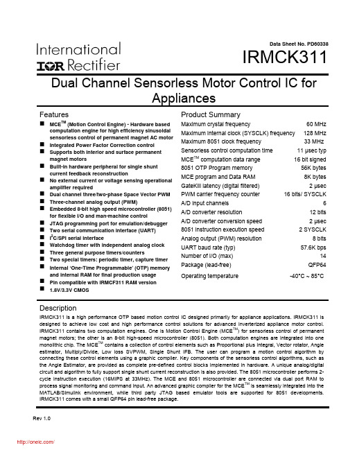
Data Sheet No. PD60338IRMCK311 Dual Channel Sensorless Motor Control IC forAppliancesFeaturesMCE TM (Motion Control Engine) - Hardware based computation engine for high efficiency sinusoidal sensorless control of permanent magnet AC motor Integrated Power Factor Correction controlSupports both interior and surface permanent magnet motorsBuilt-in hardware peripheral for single shunt current feedback reconstructionNo external current or voltage sensing operational amplifier requiredDual channel three/two-phase Space Vector PWM Three-channel analog output (PWM)Embedded 8-bit high speed microcontroller (8051) for flexible I/O and man-machine controlJTAG programming port for emulation/debugger Two serial communication interface (UART)I2C/SPI serial interfaceWatchdog timer with independent analog clockThree general purpose timers/countersTwo special timers: periodic timer, capture timer Internal ‘One-Time Programmable’ (OTP) memory and internal RAM for final production usagePin compatible with IRMCF311 RAM version1.8V/3.3V CMOS Product SummaryMaximum crystal frequency 60 MHz Maximum internal clock (SYSCLK) frequency 128 MHz Maximum 8051 clock frequency 33 MHz Sensorless control computation time 11 μsec typ MCE TM computation data range 16 bit signed 8051 OTP Program memory 56K bytes MCE program and Data RAM 8K bytes GateKill latency (digital filtered) 2 μsec PWM carrier frequency counter 16 bits/ SYSCLK A/D input channels 6 A/D converter resolution 12 bits A/D converter conversion speed 2 μsec 8051 instruction execution speed 2 SYSCLK Analog output (PWM) resolution 8 bits UART baud rate (typ) 57.6K bps Number of I/O (max) 14 Package (lead-free) QFP64 Operating temperature -40°C ~ 85°CDescriptionIRMCK311 is a high performance OTP based motion control IC designed primarily for appliance applications. IRMCK311 is designed to achieve low cost and high performance control solutions for advanced inverterized appliance motor control. IRMCK311 contains two computation engines. One is Motion Control Engine (MCE TM) for sensorless control of permanent magnet motors; the other is an 8-bit high-speed microcontroller (8051). Both computation engines are integrated into one monolithic chip. The MCE TM contains a collection of control elements such as Proportional plus Integral, Vector rotator, Angle estimator, Multiply/Divide, Low loss SVPWM, Single Shunt IFB. The user can program a motion control algorithm by connecting these control elements using a graphic compiler. Key components of the sensorless control algorithms, such as the Angle Estimator, are provided as complete pre-defined control blocks implemented in hardware. A unique analog/digital circuit and algorithm to fully support single shunt current reconstruction is also provided. The 8051 microcontroller performs 2-cycle instruction execution (16MIPS at 33MHz). The MCE and 8051 microcontroller are connected via dual port RAM to process signal monitoring and command input. An advanced graphic compiler for the MCE TM is seamlessly integrated into the MATLAB/Simulink environment, while third party JTAG based emulator tools are supported for 8051 developments. IRMCK311 comes with a small QFP64 pin lead-free package.TABLE OF CONTENTS1 Overview (5)2 IRMCK311 Block Diagram and Main Functions (6)3 Pinout (8)4 Input/Output of IRMCK311 (9)4.1 8051 Peripheral Interface Group (10)4.2 Motion Peripheral Interface Group (10)4.3 Analog Interface Group (11)4.4 Power Interface Group (11)4.5 Test Interface (12)5 Application Connections (13)6 DC Characteristics (14)6.1 Absolute Maximum Ratings (14)6.2 System Clock Frequency and Power Consumption (14)6.3 Digital I/O DC Characteristics (15)6.4 PLL and Oscillator DC Characteristics (15)6.5 Analog I/O DC Characteristics (16)6.6 Under Voltage Lockout DC Characteristics (17)6.7 AREF Characteristics (17)7 AC Characteristics (18)7.1 PLL AC Characteristics (18)7.2 Analog to Digital Converter AC Characteristics (19)7.3 Op Amp AC Characteristics (19)7.4 SYNC to SVPWM and A/D Conversion AC Timing (20)7.5 GATEKILL to SVPWM AC Timing (21)7.6 Interrupt AC Timing (21)7.7 I2C AC Timing (22)7.8 SPI AC Timing (23)7.8.1 SPI Write AC timing (23)7.8.2 SPI Read AC Timing (24)7.9 UART AC Timing (25)7.10 CAPTURE Input AC Timing (26)7.11 JTAG AC Timing (27)7.12 OTP Programming Timing (28)8 I/O Structure (29)9 Pin List (32)Dimensions (35)10 Package11 Part Marking Information (36)Information (36)12 OrderingTABLE OF FIGURESFigure 1. Typical Application Block Diagram Using IRMCK311 (5)Figure 2. IRMCK311 Internal Block Diagram (6)Figure 3. IRMCK311 Pin Configuration (8)Figure 4. Input/Output of IRMCK311 (9)Figure 5. Application Connection of IRMCK311 (13)Figure 6. Clock Frequency vs. Power Consumption (14)Figure 7 Crystal oscillator circuit (18)Figure 8 Voltage droop of sample and hold (19)Figure 9 SYNC to SVPWM and A/D conversion AC Timing (20)Figure 10 GATEKILL to SVPWM AC Timing (21)Figure 11 Interrupt AC Timing (21)Figure 12 I2C AC Timing (22)Figure 13 SPI AC Timing (23)Figure 14 SPI Read AC Timing (24)Figure 15 UART AC Timing (25)Figure 16 CAPTURE Input AC Timing (26)Figure 17 JTAG AC Timing (27)Figure 18 OTP Programming Timing (28)Figure 19 All digital I/O except motor PWM output (29)Figure 20 RESET, GATEKILL I/O (29)Figure 21 Analog input (30)Figure 22 Analog operational amplifier output and AREF I/O structure (30)Figure 23 VPP programming pin I/O structure (30)Figure 24 VSS and AVSS pin structure (31)Figure 25 VDD1 and VDDCAP pin structure (31)Figure 26 XTAL0/XTAL1 pins structure (31)TABLE OF TABLESTable 1. Absolute Maximum Ratings (14)Table 2. System Clock Frequency (14)Table 3. Digital I/O DC Characteristics (15)Table 4. PLL DC Characteristics (15)Table 5. Analog I/O DC Characteristics (16)Table 6. UVcc DC Characteristics (17)Table 7. AREF DC Characteristics (17)Table 8. PLL AC Characteristics (18)Table 9. A/D Converter AC Characteristics (19)Table 10. Current Sensing OP Amp AC Characteristics (19)Table 11. SYNC AC Characteristics (20)Table 12. GATEKILL to SVPWM AC Timing (21)Table 13. Interrupt AC Timing (21)Table 14. I2C AC Timing (22)Table 15. SPI Write AC Timing (23)Table 16. SPI Read AC Timing (24)Table 17. UART AC Timing (25)Table 18. CAPTURE AC Timing (26)Table 19. JTAG AC Timing (27)Table 20. OTP Programming Timing (28)Table 21. Pin List (32)1 OverviewIRMCK311 is a new International Rectifier integrated circuit device primarily designed as a one-chip solution for complete inverter controlled appliance dual motor control applications. Unlike a traditional microcontroller or DSP, the IRMCK311 provides a built-in closed loop sensorless control algorithm using the unique Motion Control Engine (MCE TM) for permanent magnet motors. The MCE TM consists of a collection of control elements, motion peripherals, a dedicated motion control sequencer and dual port RAM to map internal signal nodes. IRMCK311 also employs a unique single shunt current reconstruction circuit to eliminate additional analog/digital circuitry and enables a direct shunt resistor interface to the IC. The sensorless control is the same for both motors with a single shunt current sensing capability. Motion control programming is achieved using a dedicated graphical compiler integrated into the MATLAB/Simulink TM development environment. Sequencing, user interface, host communication, and upper layer control tasks can be implemented in the 8051 high-speed 8-bit microcontroller. The 8051 microcontroller is equipped with a JTAG port to facilitate emulation and debugging tools. Figure 1 shows a typical application schematic using IRMCK311.IRMCK311 is intended for volume production purpose and contains 64K bytes of OTP (One Time Programming) ROM, which can be programmed through a JTAG port. For a development purpose use, IRMCF311 contains a 48k byte of RAM in place of program OTP to facilitate an application development work. Both IRMCF311 and IRMCK311 come in the same 64-pin QFP package with identical pin configuration to facilitate PC board layout and transition to mass productionFigure 1. Typical Application Block Diagram Using IRMCK3112 IRMCK311 Block Diagram and Main FunctionsM o t i o n C o n t r o l B u sFigure 2. IRMCK311 Internal Block DiagramIRMCK311 contains the following functions for sensorless AC motor control applications:• Motion Control Engine (MCE TM )o Proportional plus Integral block o Low pass filtero Differentiator and lag (high pass filter) o Ramp o Limito Angle estimate (sensorless control) o Inverse Clark transformation o Vector rotator o Bit latch o Peak detect o Transitiono Multiply-divide (signed and unsigned)o Divide (signed and unsigned)o Addero Subtractoro Comparatoro Countero Accumulatoro Switcho Shifto ATAN (arc tangent)o Function block (any curve fitting, nonlinear function)o16-bit wide Logic operations (AND, OR, XOR, NOT, NEGATE)o MCE TM program and data memory (6K byte). Note 1o MCE TM control sequencer• 8051 microcontrollero Three 16-bit timer/counterso16-bit periodic timero16-bit analog watchdog timero16-bit capture timero Up to 36 discrete I/Oso Eleven-channel 12-bit A/DFive buffered channels (0 – 1.2V input)One unbuffered channel (0 – 1.2V input)o JTAG port (4 pins)o Up to three channels of analog output (8-bit PWM)o Two UARTo I2C/SPI porto 64K byte Note 1program One-Time Programmable memoryo2K byte data RAM. Note 2Note 1: Total size of OTP memory is 64K byte, however MCE program occupiesmaximum 8K byte which will be loaded into internal RAM at a powerup/bootprocess. Therefore only 56K byte OTP memory area is usable for 8051microcontroller.Note 2: Total size of RAM is 8K byte including MCE program, MCE data, and 8051data. Different sizes can be allocated depending on applications.3 PinoutXTAL0XTAL1P1.1/RXD P1.2/TXDVDD1VSS VDD2P1.3/SYNC/SCKP1.4/CAPP 3.6/R X D 1P 3.7/T X D 1FPWMVL FPWMUL V S SV D D 2A V D DA V S SA I N 0A R E FP 2.7/A O P W M 1P 2.6/A O P W M 0CPWMUH CPWMVH CPWMWH CPWMUL CPWMVL CPWMWL CGATEKILL VDD1VSS I F B C OI F B C +I F B C -P L L V S SP L L V D DR E S E TN CT C KP 5.3/T D IP 5.2/T D OP 5.1/T M SS D A /C S 0S C L /S O -S I /V P PP 5.0/P F C G K I L LP F C P W M V S SFGATEKILL FPWMWL VAC-VAC+VACO IPFCO IPFC+IPFC-I F B F OI F B F +I F B F -P3.0/INT2/CS1C M E X TFPWMVH FPWMUHFPWMWH A I N 1P 3.2/I N T 0Figure 3. IRMCK311 Pin Configuration4 Input/Output of IRMCK311All I/O signals of IRMCK311 are shown in Figure 4. All I/O pins are 3.3V logic interface except A/D interface pins.Figure 4. Input/Output of IRMCK3114.1 8051 Peripheral Interface GroupUART InterfaceP1.1/RXD Input, Receive data to IRMCK311, can be configured as P1.1P1.2/TXD Output, Transmit data from IRMCK311, can be configured as P1.22nd channel Receive data to IRMCK311, can be configured as P3.6 P3.6/RXD1 Input,P3.7/TXD1 Output,2nd channel Transmit data from IRMCK311, can be configured as P3.7Discrete I/O InterfaceP1.3/SYNC/SCK Input/output port 1.3, can be configured as SYNC output or SPI clock P1.4/CAP Input/output port 1.4, can be configured as Capture Timer inputP3.0/INT2/CS1 Input/output port 3.0, can be configured as external interrupt 2 or SPIchip select 1P3.2/INT0 Input/output port 3.2, can be configured as external interrupt 0Analog Output InterfaceP2.6/AOPWM0 Input/output, can be configured as 8-bit PWM output 0 withprogrammable carrier frequencyP2.7/AOPWM1 Input/output, can be configured as 8-bit PWM output 1 withprogrammable carrier frequencyCrystal InterfaceXTAL0 Input, connected to crystalXTAL1 Output, connected to crystalReset InterfaceRESET Inout, system reset, needs to be pulled up to VDD1 but doesn’t requireexternal RC time constantI2C/SPI InterfaceSCL/SO-SI/VPP Output, I2C clock output, SPI SO-SII2C Data line, Chip Select 0 of SPISDA/CS0 Input/output,P3.0/INT2/CS1 Input/output port 3.0, can be configured as external interrupt 2 or SPIchip select 1P1.3/SYNC/SCK Input/output port 1.3, can be configured as SYNC output or SPI clock 4.2 Motion Peripheral Interface GroupPWMCPWMUH Output, motor 1 PWM phase U high side gate signalCPWMUL Output, motor 1 PWM phase U low side gate signalCPWMVH Output, motor 1 PWM phase V high side gate signalCPWMVL Output, motor 1 PWM phase V low side gate signalCPWMWH Output, motor 1 PWM phase W high side gate signalCPWMWL Output, motor 1 PWM phase W low side gate signalFPWMUH Output, motor 2 PWM phase U high side gate signalFPWMUL Output, motor 2 PWM phase U low side gate signal分销商库存信息: IRIRMCK311TR。

DATASHEETDataOrdering dataProduct type description BNS 36-11ZG-ST-L101190048 Article number (ordernumber)4030661359687 EAN (European ArticleNumber)eCl@ss number, version 11.027-27-24-02eCl@ss number, version 9.027-27-24-02 ETIM number, version 7.0EC002544ETIM number, version 6.0EC002544Approvals - StandardsCertificates TÜVBGcULusGeneral dataStandards BG-GS-ET-14EN IEC 60947-5-3Coding level according to ENISO 14119LowWorking principle Magnetic driveInstallation conditions(mechanical)quasi-flushEnclosure material Glass-fibre, reinforced thermoplastic Gross weight38 gGeneral data - FeaturesIntegral system diagnostics,statusYesNumber of normally closed(NC)1Number of normally open(NO)1Number of safety contacts2Safety classificationStandards EN ISO 13849-1Mission time20 Year(s)Safety classification - Safety outputsB10D - Value Normally-closedcontact/Normally opencontact (NC/NO)25,000,000 OperationsMechanical dataActuating element MagnetDoor hinge LeftDirection of motion Head-on to the active surfaceMechanical data - Switching distances according EN IEC 60947-5-3Note (Switching distance Sn)Axial misalignment, a horizontal and vertical misalignment of the safety sensorand the actuator are tolerated. The possible misalignment depends on thedistance of the active surfaces of the sensor and the actuator. The sensorremains active within the tolerance range.7 mmAssured switching distance"ON" SaoAssured switching distance17 mm"OFF" SarMechanical data - Connection techniqueTermination Connector M8, 4-pole, Latching interlockingMechanical data - DimensionsLength of sensor13 mmWidth of sensor88 mmHeight of sensor25 mmAmbient conditionsDegree of protection IP67Ambient temperature-25 ... +70 °CStorage and transport-25 °Ctemperature, minimum+70 °CStorage and transporttemperature, maximumResistance to vibrations10 … 55 Hz, amplitude 1 mmRestistance to shock30 g / 11 msElectrical dataSwitching voltage, maximum24 VDCSwitching current, maximum0.01 ASwitching capacity, maximum0.2 WSwitching frequency,maximum5 HzStatus indicationNote (Integral SystemDiagnostics, status )The LED is illuminated when the guard is closed.Scope of deliveryScope of delivery Actuator must be ordered separately.AccessoryRecommendation (actuator)BPS 36-2Recommended safety switchgear SRB-E-301ST SRB-E-201LCNoteNote (General)The number in brackets indicate the PIN number of the connector.Ordering codeProduct type description:BNS 36-(1)(2)Z(3)-(4)-(5)(1)11 1 NO contacts/1 NC contact02 2 NC contact(2)without with diagnostic output/01 1 NC contact10 1 NO contact(3)without without LED switching conditions displayG with LED switching conditions display(4)without Pre-wired cableST with connector(5)L Door hinge on left-hand sideR Door hinge on right-hand side(6)2750Version with extended switching distance (incombination with actuator) BPS 36-1-2750 or BPS 36-2-2750)DocumentsOperating instructions and Declaration of conformityBNS 36(364.1 kB, 21.11.2022)UL CertificateBNS 36(385.0 kB, 01.08.2019)SISTEMA-VDMA library(659.5 kB, 23.03.2023)PicturesProduct picture (catalogue individual photo)ID: kbns3f33| 285.3 kB | .jpg | 352.778 x 115.006 mm - 1000 x 326 px - 72 dpi| 23.3 kB | .png | 74.083 x 23.989 mm - 210 x 68 px - 72 dpiDimensional drawing basic componentID: 1bns3g14| 24.1 kB | .cdr || 3.0 kB | .png | 74.083 x 51.506 mm - 210 x 146 px - 72 dpi| 60.6 kB | .jpg | 352.778 x 245.181 mm - 1000 x 695 px - 72 dpiDiagramID: kbns2k03| 18.7 kB | .cdr || 59.6 kB | .jpg | 352.778 x 57.503 mm - 1000 x 163 px - 72 dpi| 3.0 kB | .png | 74.083 x 11.994 mm - 210 x 34 px - 72 dpiCharacteristic curveID: kbns3a29| 165.7 kB | .jpg | 352.778 x 215.9 mm - 1000 x 612 px - 72 dpi| 110.2 kB | .png | 50.038 x 30.649 mm - 591 x 362 px - 300 dpi| 165.7 kB | .jpg | 352.778 x 215.9 mm - 1000 x 612 px - 72 dpiCharacteristic curveID: kbns3a30| 16.9 kB | .png | 74.083 x 45.156 mm - 210 x 128 px - 72 dpi| 164.2 kB | .jpg | 352.778 x 215.547 mm - 1000 x 611 px - 72 dpiContact arrangementID: km8--k4b| 17.0 kB | .cdr || 4.3 kB | .png | 74.083 x 73.025 mm - 210 x 207 px - 72 dpi| 110.6 kB | .jpg | 352.778 x 347.133 mm - 1000 x 984 px - 72 dpiOperating principleID: kbn36c02| 20.3 kB | .cdr || 52.8 kB | .jpg | 352.778 x 248.356 mm - 1000 x 704 px - 72 dpi| 1.8 kB | .png | 74.083 x 52.211 mm - 210 x 148 px - 72 dpi System componentsConnectorBNS-Y-11enables the interconnection and the connection of BNS safety sensors to acommon safety monitoring modulefor BNS 33, BNS 36, BNS 260 (with 1 NC/1 NO)A-K4P-M8-R-W-5M-GY-1-X-X-4Pre-wired cable4-poleA-K4P-M8-R-W-2M-GY-1-X-X-4Pre-wired cable4-poleA-K4P-M8-R-W-10M-GY-1-X-X-4Pre-wired cable4-poleA-K4P-M8-R-G-5M-GY-1-X-X-4Pre-wired cable4-poleA-K4P-M8-R-G-2M-GY-1-X-X-4Pre-wired cable4-poleA-K4P-M8-R-G-10M-GY-1-X-X-4Pre-wired cable4-poleAccessoriesSPACER BNS 36 SPACERto mount the magnetic safety sensor and actuator on ferromagnetic materialActuatorBPS 36-1Actuator and sensor on a mounting levelBPS 36-2Actuator 90 ° attached to the sensorControl-ModulPlug-in screw terminals with codingSTOP 0 Function1 oder 2-channel controlStart button / Auto-start2 Safety outputs 2 A1 Signalling outputPlug-in screw terminals with codingSTOP 0 FunctionMonitoring of 4 sensorsStart button / Auto-start2 Safety outputs4 Signalling outputsPlug-in screw terminals with codingSTOP 0 Function1 oder 2-channel controlStart button / Auto-start1 Auxiliary contact3 safety contactsK.A. Schmersal GmbH & Co. KG, Möddinghofe 30, 42279 WuppertalThe details and data referred to have been carefully checked. Images may diverge from original. Further technicaldata can be found in the manual. Technical amendments and errors possible.Generated on: 26/07/2023, 06:48。

产品特色大幅简化离线式LED驱动器设计●单级功率因数校正(PFC)与精确恒流(CC)输出相结合●输入/输出电容和变压器体积小●一次侧反馈控制,无需光耦电路,简化了电路设计●简化初级侧PWM调光接口●符合IEC61000-3-2标准高效节能和高兼容性●大幅提升效率,可达到85%以上●减少元件数量●总谐波失真<15%且PF>0.95●前沿、后沿和数字调光器●传感器和定时器精确稳定的性能●LED负载恒流精度不低于±5%●支持LED负载热插拔●1%-100%宽范围调光,调光无闪烁先进的保护及安全特性●通过自动重启动提供短路保护●开路故障检测模式●自动热关断重启动无论在PCB板上还是在封装上,都保证高压漏极引脚与其他所有信号引脚之间满足高压爬电要求应用●LED离线固态照明说明G7617 是一款的适用于LED调光控制的离线式两级交流/直流电源控制器,是适用于25W 输出功率的可调光LED 灯具的最优之选。
G7617符合电磁兼容性(EMC) IEC61000-3-2 标准,在120V AC或230V AC输入电压下其功率因数(PF) 可达到0.95 以上。
采用先进的数控技术来检测调光器的类型和相位,为调光器提供动态阻抗的同时可调节LED发光亮度,自动检测调光器类型和相位,从而实现了业内与模拟及数字调光器最广泛的兼容性。
G7617工作于准谐振工作模式,工作效率高,可工作于前沿后沿调光模式,也可工作于R 型、R-C型或R-L型调光控制模式。
G7617 符合热插拔LED 模块的固态照明行业标准Zhaga,同时还集成了调光功能的映射选项(位于白炽灯替代灯的NEMA SSL6 调光曲线内)。
G7617 系列有两个版本:针对120V AC输入应用进行优化的G7617-00 和针对230V AC 应用进行优化的G7617-01。
订购信息应用框图图1典型应用内部框图Vcc VinVcbVT CFGASU BisenseBdrvFdrvFisensePGNDAGND C O R E图2 内部框图引脚功能描述BV SENSE V IN BI SENSE B DRV CFG ASU V CCV CBV TFV SENSEFI SENSEF DRVAGNDPGND 图3. 引脚布局BV SENSE引脚:PFC电感电压反馈点,用于感知Boost电感的磁通状态。

SA5.0A Series500 Watt Peak Power MiniMOSORB t Zener Transient Voltage SuppressorsUnidirectionalThe SA5.0A series is designed to protect voltage sensitive components from high voltage, high energy transients. They have excellent clamping capability, high surge capability, low zener impedance and fast response time. The SA5.0A series is supplied in ON Semiconductor’s exclusive, cost-effective, highly reliable Surmetic t axial leaded package and is ideally-suited for use in communication systems, numerical controls, process controls, medical equipment, business machines, power supplies and many other industrial/consumer applications.Features•Working Peak Reverse V oltage Range − 5.0 to 170 V •Peak Power − 500 Watts @ 1.0 ms•ESD Rating of Class 3 (>16 kV) per Human Body Model •Maximum Clamp V oltage @ Peak Pulse Current•Low Leakage < 1 m A above 8.5 V•UL 497B for Isolated Loop Circuit Protection •Maximum Temperature Coefficient Specified •Response Time is typically < 1.0 ns•Pb−Free Packages are Available*Mechanical Characteristics:CASE:V oid-free, Transfer-molded, Thermosetting Plastic FINISH:All external surfaces are corrosion resistant and leads are readily solderableMAXIMUM LEAD TEMPERATURE FOR SOLDERING:230°C,1/16 in. from the case for 10 secondsPOLARITY:Cathode indicated by polarity bandMOUNTING POSITION:Any*For additional information on our Pb−Free strategy and soldering details, please download the ON Semiconductor Soldering and Mounting Techniques Reference Manual, SOLDERRM/D.Device Package Shipping†ORDERING INFORMATIONSAxxxA Axial Lead1000 Units / Box SAxxxAG Axial Lead(Pb−Free)1000 Units / Box†For information on tape and reel specifications, including part orientation and tape sizes, please refer to our T ape and Reel Packaging Specifications Brochure, BRD8011/D.SAxxxARL*Axial Lead5000 / Tape & Reel SAxxxARLG*Axial Lead(Pb−Free)5000 / Tape & Reel SAxxxALF**Axial Lead2000 Units / Box SAxxxALFG**Axial Lead(Pb−Free)2000 Units / Box*SA8.0A, SA130A, and SA160A Not Available in 5000/ Reel.** Lead formed device.MAXIMUM RATINGSRating Symbol Value Unit Peak Power Dissipation (Note 1)@ T L≤ 25°CP PK500WSteady State Power Dissipation@ T L≤ 75°C, Lead Length = 3/8 in Derated above T L = 75°C P D 3.030WmW/°CThermal Resistance, Junction−to−Lead R q JL33.3°C/W Forward Surge Current (Note 2)@ T A = 25°CI FSM70A Operating and Storage T emperature Range T J, T stg−55 to +175°CStresses exceeding Maximum Ratings may damage the device. Maximum Ratings are stress ratings only. Functional operation above the Recommended Operating Conditions is not implied. Extended exposure to stresses above the Recommended Operating Conditions may affect device reliability.1.Nonrepetitive current pulse per Figure 4 and derated above T A = 25°C per Figure2.2.1/2 sine wave (or equivalent square wave), PW = 8.3 ms, duty cycle = 4 pulses per minute.ELECTRICAL CHARACTERISTICS (T A = 25°C unlessotherwise noted, V F = 3.5 V Max. @ I F (Note 6) = 35 A)Symbol ParameterI PP Maximum Reverse Peak Pulse CurrentV C Clamping Voltage @ I PPV RWM Working Peak Reverse VoltageI R Maximum Reverse Leakage Current @ V RWMV BR Breakdown Voltage @ I TI T Test CurrentQ V BR Maximum Temperature Variation of V BRI F Forward CurrentV F Forward Voltage @ I FELECTRICAL CHARACTERISTICS (T A = 25°C unless otherwise noted, V F = 3.5 V Max. @ I F (Note 6)= 35 A)Device*DeviceMarkingV RWM(Note 3)I R @ V RWMBreakdown Voltage V C @ I PP(Note 5)Q V BRV BR (Note 4) (Volts)@ I T V C I PP Volts m A Min Nom Max mA Volts A mV/°CSA5.0A, G SA5.0A5600 6.4 6.77109.254.35 SA6.0A, G SA6.0A6600 6.677.027.371010.348.55 SA7.0A, G SA7.0A71507.788.198.6101241.76 SA7.5A, G SA7.5A7.5508.338.779.21112.938.87 SA8.0A, G†SA8.0A8258.899.369.83113.636.77 SA8.5A, G SA8.5A8.559.449.9210.4114.434.78 SA9.0A, G SA9.0A911010.5511.1115.432.59 SA10A, G SA10A10111.111.712.311729.410 SA11A, G SA11A11112.212.8513.5118.227.411 SA12A, G SA12A12113.31414.7119.925.112 SA13A, G SA13A13114.415.1515.9121.523.213 SA14A, G SA14A14115.616.417.2123.221.514 SA15A, G SA15A15116.717.618.5124.420.616 SA16A, G SA16A16117.818.7519.712619.217 SA17A, G SA17A17118.919.920.9127.618.119 SA18A, G SA18A1812021.0522.1129.217.220 SA20A, G SA20A20122.223.3524.5132.415.423 SA22A, G SA22A22124.425.6526.9135.514.125 SA24A, G SA24A24126.728.129.5138.912.828 SA26A, G SA26A26128.930.431.9142.111.930 SA28A, G SA28A28131.132.7534.4145.41131 SA30A, G SA30A30133.335.0536.8148.410.336 SA33A, G SA33A33136.738.6540.6153.39.439 SA36A, G SA36A3614042.144.2158.18.641 SA40A, G SA40A40144.446.5549.1164.57.846 SA43A, G SA43A43147.850.352.8169.47.250 SA45A, G SA45A4515052.6555.3172.7 6.952 SA48A, G SA48A48153.356.158.9177.4 6.556 SA51A, G SA51A51156.759.762.7182.4 6.161 SA58A, G SA58A58164.467.871.2193.6 5.370 SA60A, G SA60A60166.770.273.7196.8 5.271 SA64A, G SA64A64171.174.8578.61103 4.976 SA64ALF, G SA64A64171.174.8578.61103 4.976 SA70A, G SA70A70177.881.9861113 4.485 SA78A, G SA78A78186.791.2595.81126 4.095 SA90A, G SA90A901100105.51111146 3.4110 SA100A, G SA100A10011111171231162 3.1123 SA110A, G SA110A1101122128.51351177 2.8133 SA120A, G SA120A12011331401471193 2.5146 SA130A, G†SA130A1301144151.51591209 2.4158 SA150A, G SA150A15011671761851243 2.1184 SA160A, G†SA160A1601178187.51971259 1.9196 SA170A, G SA170A17011891992091275 1.8208 NOTE:Devices listed in bold, italic are ON Semiconductor Preferred devices. Preferred devices are recommended choices for future use and best overall value.3.MiniMOSORB t transients suppressor is normally selected according to the maximum working peak reverse voltage (V RWM), whichshould be equal to or greater than the dc or continuous peak operating voltage level.4.V BR measured at pulse test current I T at an ambient temperature of 25°C.5.Surge current waveform per Figure 4 and derate per Figures 1 and 2.6.1/2 sine wave (or equivalent square wave), PW = 8.3 ms, duty cycle = 4 pulses per minute*The “G’’ suffix indicates Pb−Free package available.†Not Available in the 5000/Tape & Reel.1001010.11ms 10msP P , P E A K P O W E R (k W )t p , PULSE WIDTHFigure 1. Pulse Rating Curve 1008060402000255075100125150175200P E A K P U L S E D E R A T I N G I N % O F P E A K P O W E R O R C U R R E N T @ T A = 25C T A , AMBIENT TEMPERATURE (°C)Figure 2. Pulse Derating Curve10,0001000C, C A P A C I T A N C E (p F )V BR , BREAKDOWN VOLTAGE (VOLTS)Figure 3. Capacitance versus Breakdown Voltage t, TIME (ms)Figure 4. Pulse Waveform543210P D , S T E A D Y S T A T E P O W E R D I S S I P A T I O N (W A T T S )T L , LEAD TEMPERATURE (°C)Figure 5. Steady State Power DeratingK °UL RECOGNITION*The entire series including the bidirectional CA suffix has Underwriters Laboratory Recognition for the classification of protectors (QVGV2) under the UL standard for safety 497B and File #E 116110. Many competitors only have one or two devices recognized or have recognition in a non-protective category. Some competitors have no recognition at all. With the UL497B recognition, our parts successfully passed several tests including Strike V oltage Breakdown test, Endurance Conditioning, Temperature test, Dielectric V oltage-Withstand test, Discharge test and several more.Whereas, some competitors have only passed a flammability test for the package material, we have been recognized for much more to be included in their protector category.*Applies to SA5.0A, CA − SA170A, CA.PACKAGE DIMENSIONSAXIAL LEADCASE 59AA−01ISSUE O(Similar to DO−204AC or DO−15)MiniMOSORB and Surmetic are trademarks of Semiconductor Components Industries, LLC.ON Semiconductor and are registered trademarks of Semiconductor Components Industries, LLC (SCILLC). SCILLC reserves the right to make changes without further notice to any products herein. SCILLC makes no warranty, representation or guarantee regarding the suitability of its products for any particular purpose, nor does SCILLC assume any liability arising out of the application or use of any product or circuit, and specifically disclaims any and all liability, including without limitation special, consequential or incidental damages.“Typical” parameters which may be provided in SCILLC data sheets and/or specifications can and do vary in different applications and actual performance may vary over time. All operating parameters, including “Typicals” must be validated for each customer application by customer’s technical experts. SCILLC does not convey any license under its patent rights nor the rights of others. SCILLC products are not designed, intended, or authorized for use as components in systems intended for surgical implant into the body, or other applications intended to support or sustain life, or for any other application in which the failure of the SCILLC product could create a situation where personal injury or death may occur. Should Buyer purchase or use SCILLC products for any such unintended or unauthorized application, Buyer shall indemnify and hold SCILLC and its officers, employees, subsidiaries, affiliates, and distributors harmless against all claims, costs, damages, and expenses, and reasonable attorney fees arising out of, directly or indirectly, any claim of personal injury or death associated with such unintended or unauthorized use, even if such claim alleges that SCILLC was negligent regarding the design or manufacture of the part. SCILLC is an Equal Opportunity/Affirmative Action Employer. This literature is subject to all applicable copyright laws and is not for resale in any manner.PUBLICATION ORDERING INFORMATION。

Easy temperature and humidity management using an SD card•Unparalleled measurement accuracy•A large amount of data can be stored on a single SD card.•Alarm output for immediate response when trouble occurs•Bundled with PC software for easy conversions of logging data to graphs.Ordering InformationMain unitSensor heads*Please choose this form when you buy with the calibrationcertificate.Contents of Certificate of Calibration Set: Calibration Certificate, Inspection Result, and Traceability ChartLoggers Options (Order separately)or less. (Two logger installation screws are attached.) Calibration serviceNote:1.As the sensor head and station are digitally connected, only the sensor head is subject to calibration.2.It is necessary to ship the product back to OMRON inJapan.For the most recent information on models that have been certified forsafety standards, refer to your OMRON website.Be sure to read “Safety Precautions” onpage 3.Appearance Item ModelSensor head 1.5 m type ZN-THS11-S ZN-THS11C-S *Sensor head Anchored type ZN-THS17-S ZN-THS17C-S *Appearance Item Model Power supplyLogger ZN-THX11-SA Battery/DC cableItem ModelSensor head1.5 m type Calibration Certificate,Inspection Result,Traceability chart ZN-THS11-CALSensor headAnchored typeZN-THS17-CALRatings and SpecificationsSensor headNote:1.As performance may deteriorate through the adhesion of impurities or contaminants in the environment on the sensor surface, calibration is recommended once a year.2.When ZN-THS1@@-S is exposed over a long period of time at a high humidity of 80% or higher, the humidity measurement value may be offset.In that case, expose the product at room temperature and humidity for 24 hours prior to use.3.When ZN-THS1@@-S is transferred rapidly between the places where temperature difference is large, condensation may occur on the sensor surface. In that case, the ZN-THS1@@-S may not work properly. When the product becomes wet due to condensation, allow the product to dry in dry, room temperature environment before use.4.When using the ZN-THS1@@-S under conditions with temperature of -20︒C or less or with humidity of 90% or more, acceleration of sensor deterioration may occur.5.To avoid deterioration of sensor, avoid storing the product under high temperature and high humidity for a long period of time.6.Please don’t use the product in the environment to which organic chemistry material disperses.Logger*1.Power saving mode. The indicator is always OFF in default setting. (Turns ON with button operation.)*2.It automatically writes data to the SD card when reaching the upper limit of the internal memory, and keeps recording until the capacity limit of the SD card. If the SD card is not inserted when the internal memory reaches the upper limit, recording stops. (Data can be output to the SD card by pressing the button after inserting the SD card.)*3.This mode always records the latest measured values for the upper limit of the internal memory. (When the measured values exceed the upper limit of the internal memory, the data items will be deleted beginning with the oldest data item.)*4.An alarm is output when exceeding the upper limit value or lower limit value that has been set in threshold setting mode.*5.If you use an SD card from another manufacturer, use an SDHC Class 4 or higher card. (You must confirm the operation of the SD card yourself.)*6.Nickel hydride battery and alkaline battery can be used. Manganese batteries cannot be used.*7.Battery life differs depending on measurement environment, sampling, operating mode, battery type or performance.*8.System Requirements for Enclosed PC Software (Station Utility: Setup Tool, Logging Tool, and SD Viewer ES) OS: Windows XP / Windows Vista / Windows 7 (64 Bit not supported) CPU: compatible Intel processors, 1 GHz or higher. Memory: 1 GB or more (2 GB or more recommended)Microsoft, Windows, and Windows 7 are registered trademarks of Microsoft Corporation in the United States and/or other countries.*9.The connector is type XW4B-02B1-H1, made by OMRON.ModelItem1.5 m typeAnchored typeZN-THS11-S ZN-THS11C-SZN-THS17-S ZN-THS17C-STemperatureMeasurement range-25 to 60︒C 0 to 60︒CMeasurement precision ±0.3︒C (at 25)Resolution 0.1︒C Relative humidityMeasurement range0% to 99%20% to 85%Measurement precision ±2.5% (at 25 , 10 to 85%)Resolution0.1%Weight (packaged)Approx. 300 gAccessories 1Instruction sheet, Mounting screw (M3 ⨯ 8) x 1Instruction sheet, Mounting screw (M3 ⨯ 8) ⨯ 1, Caps to secure cable Accessories 2--Calibration Certificate,Inspection Result Traceability chart --Calibration Certificate,Inspection Result Traceability chartItem ModelZN-THX11-SASensor that can be connectedThermo-Humidity Sensor Head (ZN-THS @@-S)DisplayLCD 7-segment 5-digit 2-step displayMeasurement interval 10 s, 20 s, 30 s, 1 min, 2 min, 5 min, 10 min, 20 min, 30 min, 1 h Calculation function Instantaneous value, maximum value, minimum value, average value Operating mode Normal mode, sleep mode *1Recording mode Continue *2, ring *3External output Alarm output *4 (Photocoupler output)Internal storage device Internal memory: Approx. 8,500 data itemsExternal storage device SD card (to save measured values and to save/read set values), Recommended SD card: HMC-SD291 (manufactured by OMRON) *5Power supply voltage DC input: 24 VDC ±10%, AC adapter: 100 to 240 VAC/50 to 60 Hz, Battery: 2 AAA batteries *6Battery lifeApprox. 1 year *7 (sleep mode, measurement interval of 10 minutes, with 2 AAA nickel metal hydride batteries, with SD card not inserted)Operating temperature range Main unit: 0 to 60︒COperating humidity range 20% to 85% (no condensation)Weight (packaged)Approx. 500 gAccessories Instruction Sheet, Startup Guide, Utility disk (CD-ROM) *8, Alarm output connector *9, DC cable (straight type), Ferrite coreSafety PrecautionsFor technical information and product FAQs, refer to the “Technical Guide” on your OMRON website.DimensionsSensor headWARNINGThis product is not designed or rated for ensuring safety of persons either directly or indirectly. Do not use it for such purposes.(Unit: mm)Tolerance class IT16 applies to dimensions in this data sheet unless otherwise specified.T erms and Conditions AgreementRead and understand this catalog.Please read and understand this catalog before purchasing the products. Please consult your OMRON representative if you have any questions or comments.Warranties.(a) Exclusive Warranty. Omron’s exclusive warranty is that the Products will be free from defects in materials and workmanship for a period of twelve months from the date of sale by Omron (or such other period expressed in writing by Omron). Omron disclaims all other warranties, express or implied.(b) Limitations. OMRON MAKES NO WARRANTY OR REPRESENTATION, EXPRESS OR IMPLIED, ABOUT NON-INFRINGEMENT, MERCHANTABILITY OR FITNESS FOR A PARTICULAR PURPOSE OF THE PRODUCTS. BUYER ACKNOWLEDGES THAT IT ALONE HAS DETERMINED THAT THEPRODUCTS WILL SUITABLY MEET THE REQUIREMENTS OF THEIR INTENDED USE.Omron further disclaims all warranties and responsibility of any type for claims or expenses based on infringement by the Products or otherwise of any intellectual property right. (c) Buyer Re medy. Omron’s sole obligation hereunder shall be, at Omron’s election, to (i) replace (in the form originally shipped with Buyer responsible for labor charges for removal or replacement thereof) the non-complying Product, (ii) repair the non-complying Product, or (iii) repay or credit Buyer an amount equal to the purchase price of the non-complying Product; provided that in no event shall Omron be responsible for warranty, repair, indemnity or any other claims or expenses regarding the Products unless Omron’s analysis confirms that the Products were properly handled, stored, installed and maintained and not subject to contamination, abuse, misuse or inappropriate modification. Return of any Products by Buyer must be approved in writing by Omron before shipment. Omron Companies shall not be liable for the suitability or unsuitability or the results from the use of Products in combination with any electrical or electronic components, circuits, system assemblies or any other materials or substances or environments. Any advice, recommendations or information given orally or in writing, are not to be construed as an amendment or addition to the above warranty.See /global/or contact your Omron representative for published information.Limitation on Liability; Etc.OMRON COMPANIES SHALL NOT BE LIABLE FOR SPECIAL, INDIRECT, INCIDENTAL, OR CONSEQUENTIAL DAMAGES, LOSS OF PROFITS OR PRODUCTION OR COMMERCIAL LOSS IN ANY WAY CONNECTED WITH THE PRODUCTS, WHETHER SUCH CLAIM IS BASED IN CONTRACT, WARRANTY, NEGLIGENCE OR STRICT LIABILITY.Further, in no event shall liability of Omron Companies exceed the individual price of the Product on which liability is asserted. Suitability of Use.Omron Companies shall not be responsible for conformity with any standards, codes or regulations which apply to the combination of the Product in the Buyer’s application or use of the Product. At Buyer’s request, Omron will provide applicable third party certification documents identifying ratings and limitations of use which apply to the Product. This information by itself is not sufficient for a complete determination of the suitability of the Product in combination with the end product, machine, system, or other application or use. Buyer shall be solely responsible for determining appropriateness of the particular Product with respect to Buyer’s application, product or system. Buyer shall take application responsibility in all cases.NEVER USE THE PRODUCT FOR AN APPLICATION INVOLVING SERIOUS RISK TO LIFE OR PROPERTY OR IN LARGE QUANTITIES WITHOUT ENSURING THAT THE SYSTEM AS A WHOLE HAS BEEN DESIGNED TO ADDRESS THE RISKS, AND THAT THE OMRON PRODUCT(S) IS PROPERLY RATED AND INSTALLED FOR THE INTENDED USE WITHIN THE OVERALL EQUIPMENT OR SYSTEM.Programmable Products.Omron Companies shall not be responsible for the user’s programming of a programmable Product, or any consequence thereof.Performance Data.Data presented in Omron Company websites, catalogs and other materials is provided as a guide for the user in determining suitability and does not constitute a warranty. It may represent the result of Omron’s test conditions, and the user must correlate it to actual application requirements. Actual performance is subject to the Om ron’s Warranty and Limitations of Liability.Change in Specifications.Product specifications and accessories may be changed at any time based on improvements and other reasons. It is our practice to change part numbers when published ratings or features are changed, or when significant construction changes are made. However, some specifications of the Product may be changed without any notice. When in doubt, special part numbers may be assigned to fix or establish key specifications for your application. Please consult with your Omron’s representative at any time to confirm actual specifications of purchased Product.Errors and Omissions.Information presented by Omron Companies has been checked and is believed to be accurate; however, no responsibility is assumed for clerical, typographical or proofreading errors or omissions.2013.11In the interest of product improvement, specifications are subject to change without notice. OMRON CorporationIndustrial Automation Company/(c)Copyright OMRON Corporation 2013 All Right Reserved.。

Series CWMiniature Power RockersB12I n d i c a t o r sA c c e s s o r i e sS u p p l e m e n tT a c t i l e sK e y l o c k sR o t a r i e sP u s h b u t t o n sI l l u m i n a t e d P BS l i d e s P r o g r a m m a b l eT o u c hT i l tT o g g l e sGeneral SpecificationsElectrical CapacityPower Level: For Resistive Load 6A @ 250V ACOther RatingsContact Resistance: 20 milliohms maximumInsulation Resistance: 500 megohms minimum @ 500V DCDielectric Strength: 1,500V AC minimum between contacts for 1 minute minimum3,000V AC minimum between contacts & case for 1 minute minimum Mechanical Life: 30,000 operations minimumElectrical Life: 10,000 operations minimum with Resistive Load & 6,000 operations with Inductive Load N ominal Operating Force: 2.50N Angle of Throw: 30° Operating Temperature Range: –10°C ~ +70°C (+14°F ~ +158°F)Materials & FinishesRocker: Polycarbonate Stationary Contacts:Silver alloyHousing:PolyamideBase:Laminated thermosetting sheets Movable Contactor: Brass w/silver alloy plating Contact Terminals: Copper with silver platingMovable Contacts:SilverCommon Terminals:Brass with silver platingElectrical CapacityPower Level: For Resistive Load 6A @ 250V ACOther RatingsContact Resistance:20 milliohms maximumInsulation Resistance: 500 megohms minimum @ 500V DCDielectric Strength: 1,500V AC minimum between contacts for 1 minute minimum3,000V AC minimum between contacts & case for 1 minute minimum Mechanical Life: 30,000 operations minimumElectrical Life: 10,000 operations minimum with Resistive Load & 6,000 operations with Inductive Load N ominal Operating Force: 6.50N for single pole models; 10.0N for double pole models Angle of Throw: 30° Operating Temperature Range: –10°C ~ +70°C (+14°F ~ +158°F)Materials & FinishesRocker: Polycarbonate Stationary Contacts: Silver alloy Housing:Polyamide Base: Laminated thermosetting sheets Movable Contactor: Beryllium copper w/silver alloy plating Terminals: Brass with silver platingMovable Contacts:SilverElectrical CapacityPower Level: For Resistive Load 6A @ 125V AC; 3A @ 250V AC; 4A @ 30V DCOther RatingsContact Resistance:20 milliohms maximumInsulation Resistance: 1,000 megohms minimum @ 500V DCDielectric Strength: 1,000V AC minimum between contacts for 1 minute minimum1,500V AC minimum between contacts & case for 1 minute minimum Mechanical Life: 50,000 operations minimum Electrical Life: 25,000 operations minimum N ominal Operating Force: 2.0N Angle of Throw:30° Operating Temperature Range: –25°C ~ +70°C (–13°F ~ +158°F)Materials & FinishesRocker: Glass fiber reinforced polyamide Base: LCP (Liquid Crystal Polymer) Housing:Polyamide Contact Terminals: Brass + silver with silver plating Movable Contactor: Phosphor bronze w/silver plating Common Terminals: Brass with silver platingMovable Contacts:Silver alloyCWSB CWT CWSA/Series CWMiniature Power Rockers B13I n d i c a t o r s A c c e s s o r i e s S u p p l e m e n t T a c t i l e s K e y l o c k s R o t a r i e s P u s h b u t t o n s I l l u m i n a t e d P B S l i d e s P r o g r a m m a b l e T o g g l esT o u c h T i lt Distinctive CharacteristicsCWSALow cost molded rocker.See-saw contact mechanismStable stationary contact construction for high reliability.Easily installed with snap-in mounting.Large terminal hole dimensioned .067” x .098” (1.7mm x 2.5mm) simplifies wiring and soldering.Wave Soldering (PC version): See Profile A in Supplement section. Manual Soldering: See Profile A in Supplement section.CWSBLow cost molded rocker.Snap-acting contact mechanism gives smooth actuation and audible feedback.Stable stationary contact construction for high reliability.Front panel, snap-in mounting for labor-saving installation.Solder lug/quick connect terminals can be used with connectors.Manual Soldering: See Profile B in Supplement section.CWTLow cost molded rocker in compact, slim design.See-saw contact mechanismOutstanding insulation resistance and dielectric strength.Dust proof construction protects contact area.Stable stationary contact construction for high reliability.Front panel, snap-in mounting for labor-saving installation.Terminals are molded in and epoxy sealed to lock out flux, dust, and other contaminants.Manual Soldering: See Profile A in Supplement section./Series CWMiniature Power RockersB14I n d i c a t o r sA c c e s s o r i e s S u p p l e m e n tT a c t i l e sK e y l o c k sR o t a r i e sP u s h b u t t o n sI l l u m i n a t e d P B S l i d e sP r o g r a m m a b l eT o u c h T i l t T o g g l e sSTANDARDS & CERTIFICATIONSCWSASpecific CWSA models listed below are qualified for Underwriters Laboratories Inc. recognition and Canadian Standards Association certification. cULus marking on case is standard as noted in following table.Model Ratings @ AC cULus File No. Marking on CaseCWSA11 6A @ 250V E44145 StandardCWSA126A @ 250VE44145StandardCWSBSpecific CWSB models listed below are qualified for Underwriters Laboratories Inc. recognition and Canadian Standards Association certification. cULus marking on case is standard as noted in following table.Model Ratings @ AC cULus File No. Marking on CaseCWSB11 6A @ 250V E44145 StandardCWSB216A @ 250VE44145StandardCWTSpecific CWT model listed below is qualified for Underwriters Laboratories Inc. recognition and Canadian Standards Association certification. cULus marking on case is standard as noted in following table.Model Ratings @ AC cULus File No. Marking on CaseCWT126A @ 125V E44145Standard3A @ 250V/Series CWMiniature Power RockersB15I n d i c a t o r sA c c e s s o r i e s S u p p l e m e n t T a c t i l e s K e y l o c k s R o t a r i e s P u s h b u t t o n s I l l u m i n a t e d P BS l i d e s P r o g r a m m a b l e T o g g l esT o u c hT i ltTYPICAL ORDERING EXAMPLECWSA11AANSTYPICAL SWITCH ORDERING EXAMPLESFor SPST & SPDTNo CodeNoneFor SPST 1Horizontal 2Vertical 3Dot MarkingTYPICAL ORDERING EXAMPLECWSB21AA2FCWT12AAS1* Wire harness & cable assemblies offered only in Americas* Wire harness & cable assemblies offered only in Americas* Wire harness & cable assemblies offered only in Americas/Series CWMiniature Power RockersB16I n d i c a t o r s A c c e s s o r i e sS u p p l e m e n tT a c t i l e sK e y l o c k sR o t a r i e s P u s h b u t t o n sI l l u m i n a t e d P B S l i d e sP r o g r a m m a b l eT o u c hT i l t T o g g l e sTYPICAL SWITCH DIMENSIONS FOR CWSACWSA12AANSRight Angle Single Pole • Horizontal On-Off InscriptionSolder LugSingle Pole • No InscriptionCWSA11AAN1HINSCRIPTIONSNoneNot available in double pole.No CodeHorizontal OrientationOnly On-None-Off models are available with the horizontal inscription.1Vertical OrientationOnly On-None-Off models are available with the vertical inscription.2Dot MarkingOnly Single Pole On-None-Off models are available with the dot inscription.3The IEC symbols for On-Off are supplied with Single Throw models only. Orientation of inscription must be selected.Inscription color is white ink on black.Panel Thickness .030” ~ .079” (0.75mm ~ 2.0mm)Terminal numbers are on side of switch body Terminal numbers areon side of switch bodySingle throw model doesnot have terminal 1b /Series CWMiniature Power RockersB17I n d i c a t o r s A c c e s s o r i e s S u p p l e m e n tT a c t i l e sK e y l o c k sR o t a r i e sP u s h b u t t o n sI l l u m i n a t e d P B S l i d e sP r o g r a m m a b l e T o g g l esT o u c hT i l tCWT12AAS1Single Pole • No InscriptionSolder LugTYPICAL SWITCH DIMENSIONS FOR CWSBCWSB21AA2FSingle Pole • Dot Inscription Right AngleDouble Pole • Vertical On-Off InscriptionQuick ConnectCWSB11AA3HFootprint DPSTPanel Thickness .030” ~ .079” (0.75mm ~ 2.0mm)TYPICAL SWITCH DIMENSIONS FOR CWTPanel Thickness .030” ~ .079” (0.75mm ~ 2.0mm)FootprintSPSTTerminal numbers are on bottom of switchTerminal numbers are on bottom of switchTerminal numbers are on side of switch body /分销商库存信息:NKK-SWITCHCWSB11AA2F CWSB21AA1F CWSB21AA2F CWSA11AANS CWSA11AAN1S CWSA11AAN2S CWSA11AAN3S CWSB11AAF CWSA12AANS CWT12AAS1CWSA11AAN1H CWSB11AA1F CWSB11AA3F CWT12AAS1/U CWSA12AANH CWSA11AANH CWSB11AAH CWSA11AAN2H CWSB11AA1H CWT12AAS1/UC CWSB11AA3H CWSB21AA1H CWSB21AA2H。