TENTEC气动泵
- 格式:doc
- 大小:1.34 MB
- 文档页数:8

Pressure switch based jockey pump controller2 BR124002EN June 2018 Jockey Lite pump controllers Product descriptionAcross the lineJockey pump controllersThe JOCKEY Lite - Jockey Pump Controllers operate across-the-line. Full voltage is applied to the motor for starting bythe use of a single motor starter. Starting inrush current isapproximately 600% of rated full load amperes.Product featuresCombination Motor Controllers - All JOCKEY Lite controllersare supplied with EATON combination motor controllers,which combine the circuit breaker and overload inone device.Sealed rotary handleMechanismThe rotary handle mechanism can be padlocked in theOFF position. The rotary handle mechanism does not allowthe door to be opened when turned to the ON position.XT Power controlsThe JOCKEY Touch - Jockey PumpControllers incorporateEaton’s XT Power Controls which are designed for theglobal marketplace. The XT controls carry global ratings, aresmall in size and are available in a wide variety of operatingvoltages. They are easy to install and maintain, due to their modular, plug-in design.120V Control power transformer All JOCKEY Lite pump controllers are wired with a 120V control power transformer as standard.NEMA 2 enclosures Enclosures have an oven baked powder paint finish and are supplied with NEMA 2 rating, unless otherwise ordered. Available options include: NEMA 3R, 3, 4, 4X, 12.Starting methods There are two methods of starting the controller: Auto and Hand.Dual Setting Pressure Switch A dual setting 15-290 PSI pressure switch is used to sense a drop in pressure which actuates the jockey pump contac-tor. The setting adjustment screws are used for setting the pressure range and differential. There is one set of form-Coutput contacts rated at 10A.3Jockey Lite pump controllersBR124002EN June 2018 Technical dataAcross-the-line (direct on line)Jockey pump controllersLine voltage200-208V220-240V380-415V 440-480V 550-600V 120V-1Ph 240V-1Ph Motor horsepower 1/3-20Hp1/3-20Hp 1/3-40Hp 1/3-50Hp 1/3-50Hp 1/3-2Hp 1/3-5Hp Standards & certifi cationThe JOCKEY Lite - Jockey Pump Controllers meet the requirements of the latest edition of NFPA 20 as well as meeting CE mark requirements. They meet or exceed the requirements of UL 508 [Underwriters Laboratories (UL)] and are approved by [Canadian Standards Association (CSA)].200-208V220-240V380-415V440-480V550-600VMotor HP WithstandRating (kA)Motor HP WithstandRating (kA)Motor HP WithstandRating (kA)Motor HP WithstandRating (kA)Motor HP WithstandRating (kA)15 - 2010015 - 2010020 - 4010025 - 5010040 - 5025 120V 1ph208V 1ph240V 1ph Approx. WeightMotor HP WithstandRating (kA)Motor HP WithstandRating (kA)Motor HP WithstandRating (kA)Lbs (Kg)3 - 5100 5 - 101007.5 - 1010055 (25)200-208V220-240V380-415V440-480V550-600VMotor HP WithstandRating (kA)Motor HP WithstandRating (kA)Motor HP WithstandRating (kA)Motor HP WithstandRating (kA)Motor HP WithstandRating (kA)15 - 2010015 - 2010020 - 4010025 - 5010040 - 5025 120V 1ph208V 1ph240V 1ph Approx. WeightMotor HP WithstandRating (kA)Motor HP WithstandRating (kA)Motor HP WithstandRating (kA)Lbs (Kg)3 - 5100 5 - 101007.5 - 1010055 (25)Line terminals (incoming cables)Line voltage Qty. & cable sizes Qty. & cable sizes200 - 208220 - 240380 - 415*440 - 480550 - 600Ground lugMax HP1010152030(1) #14 - 6 (CU/AL)(4) #14 - 2 (CU/AL) 2020405050(1) #14 - 1/0 (CU/AL)(4) #14 - 2 (CU/AL)Load terminals (to motor)Line voltage Qty. & cable sizes200 - 208220 - 240380 - 415*440 - 480550 - 600Single Run Double RunMax HP23557.5(1) #18 - 14 (CU/AL)(2) #18 - 14 (CU/AL) 1010152030(1) #14 - 8 (CU/AL)(2) #14 - 8 (CU/AL)2020405050(1) #14 - 2 (CU/AL)For proper cable size, refer to the most recent edition of the National Electric Code (NEC - NFPA 70)Option Selection GuideTD124016ENXTJL Jockey pump controllersFeaturesPS124001ENXTJL Jockey pump controllersT ypical specificationsApprovalsThe Jockey Pump Controller shall meet the requirements of the latest edition of NFPA 20 as well as meetingCE mark requirements. It shall meet or exceed therequirements of UL 508 [Underwriters Laboratories(UL)] standards and approved by [Canadian StandardsAssociation (CSA)].Starting typeThe controller shall be Across-the-Line type for full voltage starting.RatingsThe Controller shall have a withstand rating of 10,000symmetrical amperes @ [208V] [240V] [380V] [400V][415V] [480V] [600V] [120V single phase] [240V singlephase]The horsepower rating of the controller shall not exceed 50Hp for three (3) phase units or 10Hp for single (1) phase units.ConstructionThe controller shall include a combination Circuit Breaker/ Overload Motor Protector.The motor circuit protector shall be mechanicallyinterlocked such that the enclosure door cannot be opened when the handle is in the ON position except by a tooloperated defeater mechanism.The controller manufacturer shall manufacture thecontactor, circuit breaker, pushbuttons, and enclosures.Brand labeled components will not be accepted.Supply VoltageThe jockey pump controller shall be available in following supply voltages:A 200-208V50/60HzB 220-240V50/60HzC 380V50/60HzD 440-480V50/60HzE 550-600V50/60HzF 415V50/60HzG1 120V single phaseG2 240V single phaseJ 400V50HzK400V60Hz EnclosureThe controller shall be housed in a NEMA Type 2 (IEC IP11) drip-proof, powder baked finish, freestanding enclosure.Optional Enclosures:NEMA 3R (IEC IP14) rain-tight enclosureNEMA 4 (IEC IP66) watertight enclosureNEMA 4X (IEC IP66) watertight 304 stainless steelenclosureNEMA 4X (IEC IP66) watertight 316 stainless steelenclosureNEMA 4X (IEC IP66) watertight corrosion resistantenclosureNEMA 12 (IEC IP52) dust-tight enclosureRun Period TimerAn optional Run Period Timer shall be available.LanguagesThe controller shall be available in a variety of languages including, but not limited to:English, French, Spanish, Portuguese, Turkish.OptionsThe jockey pump controller shall have provisions to besupplied with the following options:C1 Extra Contacts “Pump Run”C2 Extra Contacts “AC Power Failure”E1 NEMA 3R - Raintight EnclosureE2 NEMA 4 - Watertight EnclosureE3 NEMA 12 - Industrial Dust Tight EnclosureE5 NEMA 4X - 304 Stainless Steel EnclosureE8 TropicalizationE9 NEMA 4X - Painted SteelE10 NEMA 4X - 316 Stainless SteelEX Export CratingPOL “Power On” LightPRL “Pump Run” LightP7 Low Suction Pressure Switch and LightP8 Low Suction ShutdownR1 Space Heater (120/240V)R2 Space Heater c/w ThermostatR3 Space Heater c/w HumidistatS SequentialStartTimerT RunPeriodTimerZ ElapsedTimeMeterJockey Lite pump controllerFeaturesManufacturerThe controller shall be of the XT JL Across-the-Line type as manufactured by EATON.2 PS124001EN June 2018 。

您与运动和控制技术领域的先行者合作,就是希望促进您的业务发展和全球的发展。
从微型电磁阀到高集成型自动化系统,我们的产品对于用于药物研发和病原体检测的救生医疗设备和科学仪器至关重要。
并且对于缩短上市时间和降低总体拥有成本也十分关键。
因此,请与派克合作,准备改变这一切吧!/precisionfluidics 1 603 595-1500目录页T2-05Helix124高效和紧凑型 13.5mm 宽泵 – 高达 800 mLPM高压泵 – 超过5.5 LPM 和高达100 PSI 的压力T2-0320高性能与尺寸比率泵 – 高达2.5 LPMLTC 系列76液体系列传送泵 – 高达 650 mLPMEZ 底座92振动隔离安装系统小型活塞泵(空气)微型泵(空气/气体)微型泵(液体)T2-0494超紧凑型、高效泵 – 高达 7.5LPMBTC-IIS 系列62应用广泛的多功能双头泵系列产品 – 高达 11 LPMBTC 系列52应用广泛的多功能泵系列产品 – 高达6 LPMLTC-IIS 系列84液体系列双头传送泵 – 高达1.5 LPMCTS 系列BTX-Connect 2836高性能紧凑型 20 mm 宽泵 – 高达 2.5 LPM多功能双头和单头泵系列,适合多种应用-高达10 LPMTTC 系列74紧凑、高效、低压泵 – 高达 6 LPMTTC-IIS 系列84紧凑、高效、低压双头泵 - 高达 11 LPM附件4Helix 微型高压泵高达100 PSI (6.9 bar)压力Parker Helix 是一款紧凑型高压泵,旨在实现小型即时临床护理仪器。
Helix 可在挑战性的高海拔环境和无法使用外部压缩空气的应用中实现高压操作。
Helix 泵可提供5.5 LPM 以上的流量和高达100 PSI (6.9 bar)的压力,为性能至关重要且空间有限的台式诊断设备提供了出色的解决方案。
• 集成了用于卸荷的X 阀,可实现高压重启• 内部飞轮可在高压下低速运行• 无油活塞• 简单的安装特性• 带有推入式接头的快速流体连接• 符合RoHS 指令和REACH 标准产品特性• 液上空气• 气动驱动•微流控芯片• 即时临床护理检验• 分子诊断• 核酸纯化•基因组学典型应用典型市场产品规格物理特性电子5微型隔Helix 微型高压泵典型流量曲线• 曲线展示了0.080"偏移泵的流量性能• 使用5.0 Vdc 控制输入时,泵将以大约4400 RPM 的转速和高达8.5 LPM的流量的状态运行,但不建议连续工作。


全国隔膜泵十大品牌气动隔膜泵品牌前十排名1.上海沈泉泵阀制造有限公司上海沈泉泵阀制造有限公司是一家专业生产,销售管道泵,排污泵,消防泵,化工泵等给排水设备的厂家,产品涉及工矿企业、农业、城市供水、石油化工、电站、船舶、冶金、高层建筑、消防供水、工业水处理和纯净水、食品、制药、锅炉、空调循环系统等行业领域。
2. 欧隆泵业股份有限公司欧隆泵业股份有限公司成立于2009年,本公司是一家专业生产泵类产品的企业;高品质的生产设备,完善的检测标准,专业的技术力量,形成了集研发设计、生产、销售和服务为一体的现代化企业。
公司主营污水泵、油浸泵、管道泵、潜水泵等产品。
产品广泛应用于农林灌溉、区域防汛、城市排水、建筑工程、污水处理的相关领域,深受客户好评。
3. 射阳县苏工泵阀厂射阳县苏工泵阀厂(始创于一九七五年)是一家专业制造泵类产品现代化企业,经过多年的创业发展,并拥有现代化最先进的电脑微机测试系统,现在是国内最先进单位。
技术力量雄厚,吸收国内外最先进的技术,采用国内和国外相结合的材料,铸铁、耐热耐腐钢、不锈钢、耐腐耐磨氟塑料合金、增强聚丙烯、耐腐蚀、耐高温、无泄露、研制成高效节能产品填补了国内外的空白。
替代了进口泵。
产品广泛用于:化工、冶金、制药、印染、电力、石油、食品、制冷、消防、暖通、国防军工、污水处理等。
并为国家一些重点工程、工业、农业、给排、环保、交通与能源开采等做出贡献。
专业生产FS型塑料离心泵、FP型增强聚炳烯离心泵、FSB-L型氟塑料合金离心泵、AFB型耐腐蚀离心泵、IHF、IH 型化工离心泵、UHB-ZK型耐腐耐磨砂浆泵、HTB-ZK型耐酸陶瓷泵、FYS型耐腐耐磨液下泵、W型旋涡泵、GC型多级离心泵、IS、IR型清水离心泵、NWL、GWL型立式泥浆泵等、泵用配件及泵用机械密封.。
开拓.奋进中的苏工泵阀厂坚持奉行以人为本的理念,诚实守信,以质取胜,薄利多销,供货及时的经营方针及完善的售后服务,深受广大客商的一致好评。

中国最新气动隔膜泵十大品牌排行榜
①上海沈泉泵业(中国水泵行业后起之秀,不锈钢泵品质好,在化工、市政、建筑、暖通、电厂等领域业绩不错,上海沈泉泵阀制造有限公司)
②连成 (中国驰名商标,上海市名牌产品,在市政、建筑、暖通、电厂等领域业绩不错,上海连成(集团)有限公司)
③凯泉(中国驰名商标,上海市著名商标,在市政、建筑、暖通、电梁禅轿厂等领域业绩不错,上海凯泉泵业(集团)有限公司)
④南方(中国驰名商标,浙江省著名商标,特泵、不锈钢多级泵做的很不错,南方泵业股份有限公司)
⑤东方(上海市著名商标,在建筑领域近两年销量很大,上海东方泵业(集团)有限公司)
⑥博山(驰名商标,山东省著名商标,在钢铁、电力、煤炭等领域业绩不错,山东博泵科技股份有限公司)
⑦新界(中国驰名商标,浙江名牌,农用水泵行业龙头企业,浙江新界泵业股份有限袭伍公司)
⑧熊猫(上海市著名商标,在建筑领域近两年销量很大,上海熊猫机械(集团)有限公司)
⑨双轮(中国驰名商标,山东省著名商标,在油田、石化、矿山、热电等领域业绩不错,上山东双轮股份有限公司)
⑩肯富来(广东省著名商标,广东省名牌,液环真空泵的始创者,广东省佛山水泵厂有限公司)
国产泵业其它品牌:广一、沈阳水泵厂、重庆水泵厂、湘电长沙水泵厂、利欧、化成HCH、凌霄、深蓝、开利、亚梅、安波、兴齐、奥利、石家庄泵业、大耐泵业、三鱼
世界十大水泵品牌
1、美国FLOWSERVE
2、德国威乐
3、美国滨特尔
4、德国凯士比(KSB)
5、日本荏原
6、德国普罗名特
7、美国ITT
8、意大利艾格尔集团
9、丹麦格兰富
10、德国耐驰集团。

Solenoid/pneumatic valves, Tiger 20002d Internet: /catalogue/...Subject to change – 2023/05Solenoid/pneumatic valves, Tiger 2000Key featuresGeneral• A complete and comprehensive range with 5/2-way and 5/3-way valves• Poppet valve for monostable func-tions or piston spool for more com-plex versions with air spring and 5/3-way valves• With flow-optimised internal func -tions for higher flow rates with the same width• Pneumatic connections G1/8, G1/4, G3/8• Diverse and flexible, side and front mounting• Pneumatic or electrical actuation • Versatile electrical connection tech-nology with F or V solenoid coil with low power consumption, can also be used with valve terminals• Functional and timeless design,enclosed front housingSolenoid coils F solenoid coilsVoltage:• 12 to 230 V DC• 12 to 240 V AC (50 to 60 Hz)Power consumption:• 4.1 to 5.5 W DC • 3.85 to 9 VA AC• For all MFH valves• Selected types conform to the ATEX Directive for potentially explosive atmospheres• Solenoid coil can be easily exchanged later• Solenoid coil not included in scope of deliveryV solenoid coils Voltage: • 24 V DCPower consumption:• 2.5 W • For all MVH valves • Low heating • Solenoid coil included in scope of deliveryManifold assembly With manifold rail PALWith manifold block PRSThe valves Tiger 2000 (without an ATEX category) can be mounted on manifold rails PAL with a common supply port or on manifold blocks PRS with a common supply port and common exhausts.The manifold rail and manifold block have 2 to 10 valve positions.H- -NoteValves for potentially explosiveatmospheres (ATEX category) are not suitable for mounting on manifold rails PAL or manifold blocks PRS.Block mounting of Tiger 2000 valves in potentially explosive atmospheres is only recommended in combination with PRS-... manifold rails.Solenoid/pneumatic valves, Tiger 2000 Product range overview3 2023/05 – Subject to change d Internet: /catalogue/...4d Internet: /catalogue/...Subject to change – 2023/05Solenoid valves, Tiger 2000Peripherals overviewMounting on manifold block14Variants MFH-5-...-BMVH-5-...-BSolenoid valves, Tiger 2000 Peripherals overview5 2023/05 – Subject to change d Internet: /catalogue/...6d Internet: /catalogue/...Subject to change – 2023/05Solenoid valves, Tiger 2000Peripherals overviewMounting on manifold rail14Variants MFH-5-...-BMVH-5-...-BSolenoid valves, Tiger 2000 Peripherals overview7 2023/05 – Subject to change d Internet: /catalogue/...Solenoid valves, Tiger 2000Type codes8d Internet: /catalogue/...Subject to change – 2023/05Solenoid valves MFH-B, Tiger 2000 Technical data – 5/2-way valves-M-Flow rate Array 750 ... 2000 l/min-P- Voltage12, 24, 42, 48 V DC24, 42, 48, 110, 230,240 V ACSets of wearing partspage 13a1)9 2023/05 – Subject to change d Internet: /catalogue/...10d Internet: /catalogue/...Subject to change – 2023/05Solenoid valves MFH-B, Tiger 2000Technical data – 5/2-way valves1)For non-reversible valves2)Corrosion resistance class CRC 1 to Festo standard FN 940070Low corrosion stress. Dry indoor application or transport and storage protection. Also applies to parts behind coverings, in the non-visible interior area, and parts which are covered in the application (e.g. drive trunnions).1)For reversible valvesMaterialsSectional view11) F solenoid coils a page 64-M-Flow rate1000 ... 2000 l/min -P- Voltage12, 24, 42, 48 V DC24, 42, 48, 110, 230,240 V AC1)ATEX valve1)Corrosion resistance class CRC 1 to Festo standard FN 940070Low corrosion stress. Dry indoor application or transport and storage protection. Also applies to parts behind coverings, in the non-visible interior area, and parts which are covered in the application (e.g. drive trunnions).1)For reversible valvesMaterialsSectional view11) F solenoid coils a page 64Technical data – 5/3-way valves -M-Flow rate1000 ... 2600 l/min-P- Voltage12, 24, 42, 48 V DC24, 42, 48, 110, 230,240 V AC1)ATEX valve1)Corrosion resistance class CRC 1 to Festo standard FN 940070Low corrosion stress. Dry indoor application or transport and storage protection. Also applies to parts behind coverings, in the non-visible interior area, and parts which are covered in the application (e.g. drive trunnions).1)With external pilot air supply and/or ATEX valves2)After long electrical actuation (> 16h), the switch-off time of 5/3-way valves can increase to max. 50 ms.3)After long electrical actuation (> 16h), the switch-off time of 5/3-way valves can increase to max. 100 ms.4)After long electrical actuation (> 16h), the switch-off time of 5/3-way valves can increase to max. 150 ms.MaterialsSectional view11) F solenoid coils a page 641) F solenoid coils a page 64-M-Flow rate750 ... 2000 l/min -P- Voltage24 V DCSets of wearing partsa page 381)Corrosion resistance class CRC 1 to Festo standard FN 940070Low corrosion stress. Dry indoor application or transport and storage protection. Also applies to parts behind coverings, in the non-visible interior area, and parts which are covered in the application (e.g. drive trunnions).1)Values for MVH-5-1/4-B-VI-XMaterialsSectional view1-M-Flow rate1000 ... 2000 l/min-P- Voltage24 V DCSets of wearing partsa page 371)Corrosion resistance class CRC 1 to Festo standard FN 940070Low corrosion stress. Dry indoor application or transport and storage protection. Also applies to parts behind coverings, in the non-visible interior area, and parts which are covered in the application (e.g. drive trunnions).MaterialsSectional view 1-M-Flow rate1000 ... 2600 l/min -P- Voltage24 V DC1)Solenoid valve MVH-5/3G-3/8-B1)Corrosion resistance class CRC 1 to Festo standard FN 940070Low corrosion stress. Dry indoor application or transport and storage protection. Also applies to parts behind coverings, in the non-visible interior area, and parts which are covered in the application (e.g. drive trunnions).1)With external pilot air2)After long electrical actuation (> 16h), the switch-off time of 5/3-way valves can increase to max. 50 ms.3)After long electrical actuation (> 16h), the switch-off time of 5/3-way valves can increase to max. 100 ms.4)After long electrical actuation (> 16h), the switch-off time of 5/3-way valves can increase to max. 150 ms.MaterialsSectional view 1Solenoid valves MVH-B, Tiger 2000 Technical data – 5/3-way valvesSolenoid valves MVH-B, Tiger 2000 Technical data – 5/3-way valvesSolenoid valves MVH-B, Tiger 2000 Technical data – 5/3-way valvesPneumatic valves, Tiger 2000Peripherals overviewMounting on manifold block Mounting on manifold rail5Pneumatic valves, Tiger 2000Type codesPneumatic valves VL, Tiger 2000 Technical data – 5/2-way valves -M-Flow rate750 ... 2000 l/minSets of wearing partsa page 49Pneumatic valves VL, Tiger 2000 Technical data – 5/2-way valves1)Corrosion resistance class CRC 1 to Festo standard FN 940070Low corrosion stress. Dry indoor application or transport and storage protection. Also applies to parts behind coverings, in the non-visible interior area, and parts which are covered in the application (e.g. drive trunnions).Pneumatic valves VL, Tiger 2000 Technical data – 5/2-way valvesPneumatic valves VL, Tiger 2000 Technical data – 5/2-way valvesPneumatic valves J, Tiger 2000Technical data – 5/2-way valves, double pilot valves-M-Flow rate1000 ... 2000 l/min1)Corrosion resistance class CRC 1 to Festo standard FN 940070Low corrosion stress. Dry indoor application or transport and storage protection. Also applies to parts behind coverings, in the non-visible interior area, and parts which are covered in the application (e.g. drive trunnions).。

气动泵用途
气动泵是一种通过压缩空气进行工作的泵类设备,其工作原理是利用空气做动力源,通过压缩和弹性等特性实现液体输送。
气动泵广泛应用于化工、石化、制药、食品、污水处理和环保等领域。
具体来说,它可以泵送各种腐蚀性介质、高温介质、易燃介质和高粘度介质等。
同时,气动泵的安全性能比较高,由于其驱动部分不使用电动点火设备,因此在易燃易爆环境下使用更加安全可靠。
此外,气动泵还适用于矿井、隧道、水利、地铁、建筑、桥梁等施工地点的注浆堵水、填充空隙、加固破碎岩层等工程,配合多组分化工类系列产品进行施工。
请注意,气动泵的具体用途可能因实际的应用场景和需求而有所不同。
在选择和使用气动泵时,需要根据实际需求和用途选择合适的泵体材料、最大扬程、最大流量、供气压力和耐用性等参数。
气动泵的主要用途包括但不限于以下方面:
1. 工程应用:在矿井、隧道、水利、地铁、建筑和桥梁等施工地点,气动泵用于注浆堵水、填充空隙以及加固破碎岩层,配合专用的化学材料(如卡弗尼填充剂、尤卡尼岩层加固剂等)进行施工。
2. 废水处理:输送废水,进行固液分离操作。
3. 化工生产:在化工厂中,气动泵可以用于输送各种流体,例如在肥皂、清洁剂、粘合剂、油墨等产品的生产和加工过程中。
4. 汽配行业:用于输送密封剂、粘结剂和其他溶剂,以及在汽车制造和维修过程中排放液体。
5. 煤矿行业:在煤矿作业中,气动泵可用来输送稀泥浆或混水等物料。
6. 通用空气动力传输:由于气动泵利用压缩空气作为动力源,它们也可以适用于需要无火花环境或者需要远距离传输且无需电源的场合。
总之,气动泵以其安全可靠、防爆性能好、可在恶劣环境下工作等优点,在许多工业领域得到了广泛应用。

DISASSEMBLY PROCEDURE1)WARNING: All air pressure in unit must be relieved prior to disassemblyof cylinder.2)During disassembly, be careful to avoid scratching sealing areas.3)Mark top of tool plate to ensure proper orientation to housing forreassembly. Locate wrench on piston rod flats and remove screw.Remove tool plate and guide rod assembly (guide rods can remain attached to tool plate.)4)Remove foot mount brackets if present.5) Remove retaining rings at both ends.6) Press on rod end to remove plug (opposite rod).7) Pull on rod to remove bushing, noting orientation of components andtheir relationship to ports. (FIGURE 1)8) Remove all seals, noting orientation.9) Clean and inspect all components. Worn or damaged componentsshould be replaced.PHD, Inc. makes no warranty as to the fitness of its products or as to the length of service life after being repaired or parts replaced by anyone other than authorized employees of PHD, Inc. be liable for loss of profits, indirect, consequential, or incidental damages arising out of the use of PHD products.REASSEMBLY PROCEDURE1)Be careful to avoid damaging seals during assembly.2) A petroleum-based oil or grease used for lubrication of air cylindersshould be used during assembly.3)Retaining rings should always be installed with sharp edge outwardfrom cylinder.continued on reverse side1)Lubricate o-ring and place into second groove of body. (FIGURE 2)2) For standard units, place bore plug into body and secure withretaining ring.3) For shock pad units, place shock pad at bottom of cylinder grooves,making sure shock pad is flat and cannot slide into bore. Then install bore plug onto shock pad and secure with retaining ring.BUSHING1) Replace and lubricate seals. Care should be taken to ensure properorientation of rod seal and bushing. (FIGURE 3)PISTON1) Lubricate and replace piston seal.PISTON AND ROD TO BODY (single rod units only)1) Lubricate cylinder bore, piston rod, seals, and bushings.2) Lubricate o-ring and place into second groove in body for bushing end.(FIGURE 2)3) Assemble bushing onto rod using a turning motion to work rod sealover rod end. Check for proper orientation.4) Place piston rod assembly into cylinder bore and press bushing ontostatic o-ring seal and secure with retaining ring.PISTON AND ROD TO BODY (double rod units only)1) Lubricate cylinder bore, piston rod, seals, and bushings.2) Lubricate o-ring and place into second groove in body for bushing end.(FIGURE 2)3) Assemble one bushing onto rod using a turning motion to work rodseal over rod end. Check for proper orientation.4) Place piston rod assembly into cylinder bore and press bushing ontostatic o-ring seal and secure with retaining ring.5) Place the other bushing onto rod using a turning motion to work rodseal over rod end. Check for proper orientation.6) Press second bushing static o-ring seal and secure with retaining ring.PART NO: 6441-539SERIES CT CYLINDER REPAIR PROCEDURES (continued)TOOL PLATE TO ROD AND GUIDE RODS1)If used, ensure that foot mount brackets are attached to body prior to attaching the tool plate and guide rod assembly to the piston rod.2) Lubricate guide rod bushings in body (FIGURE 4).3) Apply thread locker to guide rod screws and loosely assemble guide rods to tool plate. Assemble guide rods and tool plate to body (ifrebuilding unit, tool plate and guide rods must be reassembled with the same orientation to body as when originally assembled at factory).4) Apply thread locker to piston rod screw and loosely assemble rod to tool plate.5) With tool plate in retracted position , torque guide rod screws to tool plate per CHART 1. Hand cycle unit to check for free movement. Loosen and re-torque guide rod screws if binding occurs.6) With tool plate in retracted position , torque piston rod screw to tool plate per CHART 1. Loosen and re-torque screw if binding prevents unit from cycling at 20 psi [1.4 bar].BORE SIZE 12/1620/2532/4050/63in-lb 416060130Nm 4.67715GUIDE ROD SCREW TORQUE in-lb 41110300450Nm 4.612.53451PISTON RODSCREW TORQUE CHART 1。

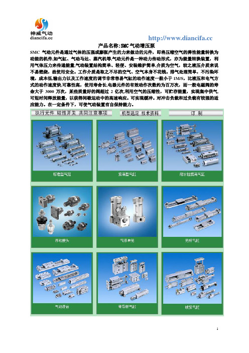
产品名称:SMC气动增压泵
SMC气动元件是通过气体的压强或膨胀产生的力来做功的元件,即将压缩空气的弹性能量转换为动能的机件,如气缸、气动马达、蒸汽机等,气动元件是一种动力传动形式,亦为能量转换装置,利用气体压力来传递能量,气动装置结构简单、轻便、安装维护简单,介质为空气,较之液压介质来说不易燃烧,故使用安全。
工作介质是取之不尽的空气、空气本身不花钱。
排气处理简单,不污染环境,成本低,输出力以及工作速度的调节非常容易气缸的动作速度一般小于1M/S,比液压和电气方式的动作速度快,可靠性高,使用寿命长,电器元件的有效动作次数约为百万次,而一般电磁阀的寿命大于3000万次,某些质量好的阀超过2亿次,利用空气的压缩性,可贮存能量,实现集中供气,可短时间释放能量,以获得间歇运动中的高速响应。
可实现缓冲。
对冲击负载和过负载有较强的适应能力。
在一定条件下,可使气动装置有自保持能力。

0914 • © Titan Tool Inc. All Rights Reserved. Form No. 0552841HNOTE: This manual contains importantwarnings and instructions. Please read and retain for reference.Owner’s ManualDo not use this equipment before reading this manual!ADVANTAGE 400Electric Piston PumpRegister your product online at:Serial Number*_ _ _ _ _ _ _ _ _ _* See page 3 for location0552054Model 0552072Model 05520712 © Titan Tool Inc. All rights reserved.© Titan Tool Inc. All rights reserved. 34 © Titan Tool Inc. All rights reserved.© Titan Tool Inc. All rights reserved.56 © Titan Tool Inc. All rights reserved.© Titan Tool Inc. All rights reserved.78 © Titan Tool Inc. All rights reserved.© Titan Tool Inc. All rights reserved.9© Titan Tool Inc. All rights reserved.© Titan Tool Inc. All rights reserved.11ProblemA. The unit will not run.B. The unit will not prime.C. The unit will not build ormaintain pressure.D. Fluid leakage at the upper endof the fluid section.E. Excessive surge at the spraygun.F. Poor spray pattern.G. The unit lacks power.cause1. The unit is not plugged in.2. Tripped breaker.3. The pressure is set too low (pressurecontrol knob set at minimum setting doesnot supply power to unit).4. Faulty or loose wiring.5. Excessive motor temperature.1. The PRIME/SPRAY valve is in the SPRAYposition.2. Air leak in the siphon tube/suction set.3. The pump filter and/or inlet screen isclogged.4. The siphon tube/suction set is clogged.1. The spray tip is worn.2. The spray tip is too large.3. The pressure control knob is not setproperly.4. The pump filter, gun filter, or inlet screen isclogged.5. Material flows from the return hose whenthe PRIME/SPRAY valve is in the SPRAYposition.6. Air leak in the siphon tube/suction set.7. There is external fluid leak.8. There is an internal fluid section leak(packings are worn and/or dirty, valve ballsare worn).9. Worn valve seats10. Motor powers but fails to rotate1. The upper packings are worn.2. The piston rod is worn.1. Wrong type of airless spray hose.2. The spray tip worn or too large.3. Excessive pressure.1. The spray tip is too large for the materialbeing used.2. Incorrect pressure setting.3. Insufficient fluid delivery.4. The material being sprayed is too viscous.1. The pressure adjustment is too low.2. Improper voltage supply.Solution1. Plug the unit in.2. Reset the breaker.3. Turn the pressure control knob clockwise to supplypower to the unit and increase the pressure setting.4. Inspect or take to a Titan authorized service center.5. Allow motor to cool.1. Rotate the PRIME/SPRAY valve clockwise to thePRIME position.2. Check the siphon tube/suction set connection andtighten or re-tape the connection with PTFE tape.3. Remove the pump filter element and clean. Removethe inlet screen and clean.4. Remove the siphon tube/suction set and clean.1. Replace the spray tip following the instructions thatcame with the spray gun.2. Replace the spray tip with a tip that has a smallerorifice following the instructions that came with thespray gun.3. Turn the pressure control knob clockwise to increasethe pressure setting.4. Remove the pump filter element and clean. Removethe gun filter and clean. Remove the inlet screenand clean.5. Clean or replace the PRIME/SPRAY valve.6. Check the siphon tube/suction set connection andtighten or re-tape the connection with PTFE tape.7. Check for external leaks at all connections. Tightenconnections, if necessary.8. Clean the valves and service the fluid sectionfollowing the “Servicing the Fluid Section” procedurein the Maintenance section of this manual.9. Reverse or replace the valve seats following the“Servicing the Fluid Section” procedure in theMaintenance section of this manual.10. Take unit to a Titan authorized service center.1. Repack the pump following the “Servicing the FluidSection” procedure in the Maintenance section of thismanual.2. Replace the piston rod following the “Servicing theFluid Section” procedure in the Maintenance sectionof this manual.1. Replace hose with a minimum of 50’ of 1/4”grounded textile braid airless paint spray hose.2. Replace the spray tip following the instructions thatcame with the spray gun.3. Rotate the pressure control knob counterclockwise todecrease spray pressure.1. Replace the spray tip with a new or smaller spray tipfollowing the instructions that came with the spraygun.2. Rotate the pressure control knob to adjust thepressure for a proper spray pattern.3. Clean all screens and filters.4. Add solvent to the material according to themanufacturer’s recommendations.1. Rotate the pressure control knob clockwise toincrease the pressure setting.2. Reconnect the input voltage for 120V AC.Troubleshooting© Titan Tool Inc. All rights reserved.Notes© Titan Tool Inc. All rights reserved.13Parts ListMain Assembly17181916131415Item Part # Description Quantity1 0551540 Motor assembly (includes items 2–7and items 25, 29, and 30 in theGear Box Assembly parts list) (1)2 770-099 Tie wrap (1)3 704-206 Capacitor (1)Suction Set Assembly1234567Item Part # Description Quantity 1 0558672A Siphon tube assembly(includes items 1-7) (1)2 0558659A Return hose (1)3 0279459 Hose clip (1)4 700-805 Inlet screen (1)5 9871105 O-ring (2)6 9822526 Retaining ring (1)7 9850638 Tie wrap (2)704-109 O-ring (for hot solvents, optional)LabelsPart # Description0552720 Logo label, front0552722 Logo label, left0552722 Logo label, right0551485 Warning label, explosion/injection0295805 Shock hazard label0507856 PRIME/SPRAY labelItem Part # Description Quantity4 704-285A Fan shroud (2)5 9802891 Screw (2)6 704-250 Fan (1)7 9804916 Fan screw (1)0508645 Motor Brush Kit© Titan Tool Inc. All rights reserved.19Gear Box Assembly© Titan Tool Inc. All rights reserved.Item Part #Description Quantity 1 700-139 Screw ........................................................4 2 0558301 Front cover ...............................................1 3 0508208 Slider assembly ........................................1 4 0508572 Crankshaft/gear assembly ........................1 5 704-174 Thrust washer ...........................................1 6 704-176 Second stage gear ...................................1 7 0509219 Screw ........................................................1 8 700-771 Pressure control knob ...............................1 9 0551522 Knob housing ............................................1 10 02712 Knob spring ..............................................1 11 9822522 Washer .....................................................1 12 806-032 Plunger .....................................................1 13 800-741 Power cord assembly (stand) ...................1 806-213 Power cord assembly (low boy and upright cart)Item Part #Description Quantity 14 9800340 Ground screw ...........................................1 15 0551112 Transducer assembly (includes o-ring) ....1 16 704-211A Circuit breaker ..........................................1 17 9850936 ON/OFF switch .........................................1 18 03662 Microswitch insulator ................................1 19 0295490 Microswitch ...............................................1 20 9800604 Screw ........................................................2 21 704-281 Port plug ...................................................1 22 700-139 Screw ........................................................4 23 0523527A Heat sink / relay assembly........................1 24 806-100A Housing assembly (includes item 17).......1 0551520 Mechanical control assembly (includes items 9–12)Stand Assembly 21354678109 Item Part # Description Quantity 1 700-761 Cord wrap .................................................1 2 9885546 Plug ..........................................................4 3 0551526 Left leg assembly(includes items 1, 2, and 7) ......................1 4 704-244 Clip assembly ...........................................1 5 0551434 Screw ........................................................1 6 700-1041 Drip cup ....................................................1 7 700-069 Screw ........................................................2 8 226-001 Nut ............................................................1 9 0551524 Right leg assembly(includes items 2, 4, 5, 6, 8, and 10)109805230Screw (1)Upright Cart assembly (P/N 0551110)12354 Item Part # Description Quantity 1 0551660 Cart weldment (includes item 5) ...............1 2 9890104 Cap ...........................................................2 3 0294534 Spacer ......................................................4 4 0278373 Wheel .......................................................2 5 9885546 Plug . (4)Low Boy cart AssemblyElectrical Schematic91011121314151617182019123467835 Item Part # Description Quantity 1 0551608 Cart weldment (includes items6 and 14) .1 2 704-291 Roll pin ......................................................2 3 0294534 Wheel spacer ............................................4 4 0270394 Wheel .......................................................2 5 9890104 Cap ...........................................................2 6 9885546 Plug ..........................................................27 0295615 Lock nut ....................................................28 9805230 Screw ........................................................19 773-918 Screw ........................................................2 10 0551551 Mounting bracket, left ...............................1 110551552Mounting bracket, right (1)Item Part # Description Quantity 12 856-921 Screw ........................................................4 13 856-002 Washer .....................................................4 14 806-033 Plug ..........................................................2 15 590-506 Handle washer ..........................................2 16 590-508 Roll pin ......................................................2 17 9841504 Snap button ..............................................2 18 590-504 Sleeve .......................................................2 19 0551609 Handle asssembly(includes items 12, 13, and 15–18............1 20700-1041Drip cup (1)NOTE: All electrical work should be performed bya Titan authorized service center.WarrantyTitan Tool, Inc., (“Titan”) warrants that at the time of delivery to the original purchaser for use (“End User”), the equipment covered by this warranty is free from defects in material and workmanship. With the exception of any special, limited, or extended warranty published by Titan, Titan’s obligation under this warranty is limited to replacing or repairing without charge those parts which, to Titan’s reasonable satisfaction, are shown to be defective within twelve (12) months after sale to the End User. This warranty applies only when the unit is installed and operated in accordance with the recommendations and instructions of Titan.This warranty does not apply in the case of damage or wear caused by abrasion, corrosion or misuse, negligence, accident, faulty installation, substitution of non-Titan component parts, or tampering with the unit in a manner to impair normal operation.Defective parts are to be returned to an authorized Titan sales/service outlet. All transportation charges, including return to thefactory, if necessary, are to be borne and prepaid by the End User. Repaired or replaced equipment will be returned to the End User transportation prepaid.THERE IS NO OTHER EXPRESS WARRANTY. TITAN HEREBY DISCLAIMS ANY AND ALL IMPLIED WARRANTIES INCLUDING, BUT NOT LIMITED TO, THOSE OF MERCHANTABILITY AND FITNESS FOR A PARTICULAR PURPOSE, TO THE EXTENT PERMITTED BY LAW. THE DURATION OF ANY IMPLIED WARRANTIES WHICH CANNOT BE DISCLAIMED IS LIMITED TO THE TIME PERIOD SPECIFIED IN THE EXPRESS WARRANTY. IN NO CASE SHALL TITAN LIABILITY EXCEED THE AMOUNT OF THE PURCHASE PRICE. LIABILITY FOR CONSEQUENTIAL, INCIDENTAL OR SPECIAL DAMAGES UNDER ANY AND ALL WARRANTIES IS EXCLUDED TO THE EXTENT PERMITTED BY LAW.TITAN MAKES NO WARRANTY AND DISCLAIMS ALL IMPLIED WARRANTIES OF MERCHANTABILITY AND FITNESS FOR A PARTICULAR PURPOSE WITH RESPECT TO ACCESSORIES, EQUIPMENT, MATERIALS OR COMPONENTS SOLD BUT NOT MANUFACTURED BY TITAN. THOSE ITEMS SOLD, BUT NOT MANUFACTURED BY TITAN (SUCH AS GAS ENGINES, SWITCHES, HOSES, ETC.) ARE SUBJECT TO THE WARRANTY, IF ANY, OF THEIR MANUFACTURER. TITAN WILL PROVIDE THE PURCHASER WITH REASONABLE ASSISTANCE IN MAKING ANY CLAIM FOR BREACH OF THESE WARRANTIES.Material Safety Data Sheets (MSDS) are available on Titan’s website or by calling Customer Service.United States Sales & Service 1770 Fernbrook Lane Minneapolis, MN Phone:Fax:1-800-526-53621-800-528-48261770 Fernbrook Lane Minneapolis, MN 55447Fax:1-763-519-3509International***************************。

胜佰德说明书
1、用内六角圆柱头螺钉将四个承脚固定在支撑板上。
2、用内角圆柱头螺钉将两个支撑脚固定在支撑上,保持支撑脚稳定。
3、将塑料隔膜泵放在支撑板上,用六角螺钉栓M8X25,I型六角螺母将隔膜泵固定在支撑板上。
4、进气阀总成接口拧紧隔膜泵的进气口接头上,保证进气阀总成水平。
5、从隔膜泵上取下密封套,将过滤总成进料口插入隔膜泵的进料扣上。
6、将过滤总成泄压管连接在出料阀门下的出料口,并拧紧,完整机安装。
7、将涂料输送管与隔膜泵的涂料出口阀门总成连接。
8、将过滤总成进料管与泄压管放入容器内。
9、检查进料阀门总成与进气开关总成保持关闭状态。
10、将隔膜泵进气开关总成与气源连接。
11、打开进气开关总成。
12、打开出料阀门总成,进入工作状态。
13、正确调节隔膜泵的工作气压,可以通过隔膜泵的进气开关总成的调压旋钮,进行调节工作压力,顺时针是加压,逆时针是减压。
14、作业完毕,必须将隔膜泵内的溶液排尽;(先关闭出料阀
门,打开泄压阀们,将储料桶溶液排尽,关闭进气开关总成进行清洗程序)。
15、将过滤总成放入盛有清洗溶液的容器内,打开出料阀门下的出料口,关闭左右出料口。
16、打开隔膜泵的进气开关总成,是泵工作5-10分钟。
17、从容器内提起进料管,使机器正常运转,排完泵内清洗的溶液,关闭进气开关总成,断开气源,清洗完成。

• Turbo-Flo ™•T1 - 1/2" (12.7 mm) 金属泵 • T2 - 1" (25.4 mm) 金属泵• T4 - 1 1/2" (38.1 mm) 金属泵 • T8 - 2" (50.8 mm) 金属泵 • T15 - 3" (76.2 mm) 金属泵 • T20 - 4" (101.6 mm) 金属泵威尔顿 T1 - 1/2" (12.7 mm) 金属泵 技术参数口径:1/2"最大流量:14.5GPM (53.9LPM) 最大工作压力:125PSI (8.6BAR)接液部结构材质:铝合金、316不锈钢、镍基合金干吸:5' (1.6m)可通过最大颗粒:1/16" (1.6mm)弹性体:聚氨脂、丁晴橡胶、氟化橡胶、SaniFlex ™、特氟龙PTFE 、Wil-Flex ™各种材质的温度范围 聚丙烯0°C(32°F) ~ +79°C(+175°F) 碳充乙缩醛-28.9°C(-20°F) ~ + 65.6°C(+150°F) 聚偏二氟乙烯-12.2°C(-10°F) ~ + 107.2°C(+225°F) 特氟龙®PFA(½" UPII&UPIII)-28.9°C(-20°F) ~ + 148.9°C(+300°F) 特氟龙®PFA(½" & 1½")-28.9°C(-20°F) ~ + 107.2°C(+225°F)尺寸- T1 Array(金属泵)序号公制(mm) 英制(inch)A 28.6 1 1/8B 115.9 4 9/16C 198.5 7 13/16D 203.2 8E 207.2 8 5/32F 222.3 8 3/4G 174.6 6 7/8H 139.7 5 1/2 J 111.9 4 13/32 K 82.6 3 1/4 L 101.6 4M 30.2 1 3/16 N 30.2 1 3/16 P 7.1 9/32* 进出水口可供BSP英制螺纹口径:1"最大流量:35GPM (132.5LPM)最大工作压力:125PSI (8.6BAR)接液部结构材质:铝合金、316不锈钢、镍基合金干吸:17' (5.2m)可通过最大颗粒:1/8" (3.17mm)弹性体:聚氨脂、氯丁橡胶、丁晴橡胶、三元橡胶、氟化橡胶、SaniFlex™、特氟龙PTFE、Wil-Flex™各种材质的温度范围聚丙烯0°C(32°F) ~ +79°C(+175°F)碳充乙缩醛-28.9°C(-20°F) ~ + 65.6°C(+150°F)聚偏二氟乙烯-12.2°C(-10°F) ~ + 107.2°C(+225°F)特氟龙®PFA(½" UPII&UPIII)-28.9°C(-20°F) ~ + 148.9°C(+300°F)特氟龙®PFA(½" & 1½")-28.9°C(-20°F) ~ + 107.2°C(+225°F)尺寸- T2 Array(金属泵)序号公制(mm) 英制(inch)A 267.5 10 17/32B 36.5 1 7/16C 138.0 5 7/16D 254.0 10E 279.4 11F 28.6 1 1/8G 47.6 1 7/8H 95.3 3 3/4 J 77.0 3 1/32 K 184.2 7 1/4 L 209.6 8 1/4 M 171.5 6 3/4 N 106.4 4 3/16 P 127.0 5R 7.9 5/16S 51.6 2 1/32 T 31.8 1 1/4* 进出水口可供BSP英制螺纹威尔顿T4 - 1 1/2" (38.1 mm) 金属泵技术参数口径:1 1/2"最大流量:81GPM (306.6LPM)最大工作压力:125PSI (8.6BAR)接液部结构材质:铝合金、316不锈钢、铸铁、镍基合金干吸:18' (5.5m)可通过最大颗粒:3/16" (4.76mm)弹性体:聚氨脂、氯丁橡胶、丁晴橡胶、三元橡胶、氟化橡胶、SaniFlex™、特氟龙PTFE、Wil-Flex™各种材质的温度范围聚丙烯0°C(32°F) ~ +79°C(+175°F)碳充乙缩醛-28.9°C(-20°F) ~ + 65.6°C(+150°F)聚偏二氟乙烯-12.2°C(-10°F) ~ + 107.2°C(+225°F)特氟龙®PFA(½" UPII&UPIII)-28.9°C(-20°F) ~ + 148.9°C(+300°F)特氟龙®PFA(½" & 1½")-28.9°C(-20°F) ~ + 107.2°C(+225°F)尺寸- T4 Array(金属泵)序号公制(mm) 英制(inch)A 369.1 14 17/32B 62.7 2 15/32C 224.6 8 27/32D 428.6 16 7/8E 287.4 11 5/16F 261.9 10 5/16G 223.8 8 3/16H 152.4 6J 177.8 7K 50.8 2L 11.7 3 1/32 M 335.7 13 7/32 N 222.3 8 3/4 P 150.8 5 15/16 R 194.5 7 21/32 S 48.4 1 29/32 T 12.7 1/2* 进出水口可供BSP英制螺纹口径:2"最大流量:163GPM (617.0LPM)最大工作压力:125PSI (8.6BAR)接液部结构材质:铝合金、316不锈钢、铸铁、镍基合金干吸:21' (6.4m)可通过最大颗粒:1/4" (6.35mm)弹性体:聚氨脂、氯丁橡胶、丁晴橡胶、三元橡胶、氟化橡胶、SaniFlex™、特氟龙PTFE、Wil-Flex™各种材质的温度范围聚丙烯0°C(32°F) ~ +79°C(+175°F)碳充乙缩醛-28.9°C(-20°F) ~ + 65.6°C(+150°F)聚偏二氟乙烯-12.2°C(-10°F) ~ + 107.2°C(+225°F)特氟龙®PFA(½" UPII&UPIII)-28.9°C(-20°F) ~ + 148.9°C(+300°F)特氟龙®PFA(½" & 1½")-28.9°C(-20°F) ~ + 107.2°C(+225°F)尺寸- T8 Array(金属泵)序号公制(mm) 英制(inch)A 404.0 15 29/32B 47.6 1 7/8C 628.7 24 3/4D 669.2 26 11/32E 372.3 14 21/32F 57.2 2 1/4G 61.7 2 7/16H 270.7 10 21/32 J 342.9 13 1/2 K 229.4 9 1/32 L 254.0 10M 255.6 10 1/16 N 313.5 12 11/32 P 14.3 9/16R 63.5 2 1/2 S 51.6 2 1/32 T 281.8 11 3/32 U 101.6 4V 280.2 11 1/32 W 386.6 15 7/32 X Ø14.3 Ø9/16* 进出水口可供BSP英制螺纹口径:3"最大流量:232GPM (878.1LPM)最大工作压力:125PSI (8.6BAR)接液部结构材质:铝合金、316不锈钢、铸铁、镍基合金干吸:19' (5.8m)可通过最大颗粒:3/8" (9.5mm)弹性体:聚氨脂、氯丁橡胶、丁晴橡胶、三元橡胶、氟化橡胶、SaniFlex™、特氟龙PTFE、Wil-Flex™各种材质的温度范围聚丙烯0°C(32°F) ~ +79°C(+175°F)碳充乙缩醛-28.9°C(-20°F) ~ + 65.6°C(+150°F)聚偏二氟乙烯-12.2°C(-10°F) ~ + 107.2°C(+225°F)特氟龙®PFA(½" UPII&UPIII)-28.9°C(-20°F) ~ + 148.9°C(+300°F)特氟龙®PFA(½" & 1½")-28.9°C(-20°F) ~ + 107.2°C(+225°F)尺寸- T15 Array(金属泵)序号公制(mm) 英制(inch)A 505.2 19 29/32B 59.5 2 11/32C 760.6 29 31/32D 821.7 32 3/8E 419.1 16 1/2F 71.4 2 13/16G 82.6 3 1/4H 312.5 12 5/16 J 425.5 16 3/4 K 360.4 14 3/16 L 304.8 12M 257.8 10 5/32 N 281.8 11 3/32 P 15.9 5/8R 69.9 2 3/4 S 65.8 2 19/32 T 305.4 12 1/32 U 42.9 1 11/16 V 305.4 12 1/32 W 475.9 18 3/4 X Ø15.9 Ø5/8* 进出水口可供BSP英制螺纹威尔顿T20 - 4" (101.6 mm) 金属泵技术参数口径:4"最大流量:275GPM (1040.0LPM)最大工作压力:125PSI (8.6BAR)接液部结构材质:铸铁干吸:12' (3.7m)可通过最大颗粒:1 3/8" (35mm)弹性体:聚氨脂、三元橡胶、氟化橡胶、SaniFlex™、特氟龙PTFE、Wil-Flex™各种材质的温度范围聚丙烯0°C(32°F) ~ +79°C(+175°F)碳充乙缩醛-28.9°C(-20°F) ~ + 65.6°C(+150°F)聚偏二氟乙烯-12.2°C(-10°F) ~ + 107.2°C(+225°F)特氟龙®PFA(½" UPII&UPIII)-28.9°C(-20°F) ~ + 148.9°C(+300°F)特氟龙®PFA(½" & 1½")-28.9°C(-20°F) ~ + 107.2°C(+225°F)威尔顿T20 - 4" (101.6 mm) 金属泵结构图尺寸- T20 Array(金属泵)序号公制(mm) 英制(inch)A 943 37.13B 825 32.50C 552 21.75D 438 17.25E 330 13F 118 4.63G 156 6.13H 158 6.25J 210 8.25K 229 9L 102 4M 190 7.5N 19 0.75P 454 17.88 R 375 14.75 S 330 13T 279 11U 14 0.56。

HI-FORCE HTWP21系列气动扳手泵操作手册Hi-Force HTWP21 系列气动扳手泵是特别为操作工作压力为700 bar (10 000 psi) 的双作用高压液压扭矩扳手设计,本使用说明适用于以下型号:HTWP2140P –气源压力7.0 bar气动扳手泵使用前请仔细查看泵上铭牌的产品信息。
安全说明在操作泵之前请认真仔细阅读这些操作说明和安全事项否则可能会导致人身伤亡或设备损坏●请确认连接到设备上的泵是完好无损的,并且是在700 Bar压力下进行操作。
●在操作泵时,总是放置在平坦的水平面上。
●在使用或者运输时,不要将泵倒置,侧放。
●检查软管是否损坏或者磨损。
不要使用已经磨损,弯折,损坏和泄露的软管。
●不要使用软管来拖拉泵或者扭矩扳手。
●不要使用已经大幅度弯折和扭曲的软管。
●不要手拉带有压力的软管。
从软管中漏出的带有压力的液压油可以穿透皮肤。
如果液压油进入皮肤,这是十分严重的医疗紧急情况。
需要立即看医生。
●在液压软管和TWS/TWH还没有连接到泵的时候,请不要启动泵。
●在操作泵时,请配带好眼,耳和手的防护设备。
●当需要对泵进行维护保养或者调试时,请断开气源。
(除了压力释放阀的调试)HI-FORCE HTWP21系列气动扳手泵操作手册零件识别请参考下图:1. 油箱2. 油温/位表3. 注油呼吸盖4. 电机5. 油压力表6. 可调式压力释放阀7. 扳手前进接头 (最大工作压力700Bar)8. 扳手回缩接头 (最大工作压力700Bar)9. 放油塞10. 空气压力表11. 线控信号连接12. 线控气源连接13. 空气压力调节器14. 空气润滑器控制15. 空气润滑存储杯16. 线控软管17. 控制面板18. 排气消声器19. 气源进口G3/8” (3/8” BSP)HI-FORCE HTWP21系列气动扳手泵操作手册HI-FORCE HTWP21系列气动扳手泵操作手册操作前准备打开包装后立即检查泵是否无损坏,一旦发现损坏请立即联系承运商。

气动泵的种类气动泵,又称空气动力泵,是一种以压缩空气为动力源的输送机械。
根据不同的应用场景和需求,气动泵可以分为多种类型。
按照工作压力和流量的不同,气动泵可以分为手动气动泵、气动膜泵、手推气动泵和气动隔膜泵。
其中,手动气动泵的压力和流量较小,适用于小容量的充气、排气、泵送、点胶等操作。
气动膜泵则具有较大的压力和流量,适用于输送粘度较高的介质、泵送污水、糊状物等。
手推气动泵则可带移动,适用于需要频繁操作的场合。
气动隔膜泵则具有结构简单、密封性能好等特点,适用于输送腐蚀性介质、易燃易爆介质等。
另外,根据泵的具体结构和用途,气动泵还可以分为隔膜泵、柱塞泵、活塞泵、离心泵、涡轮泵、偏心泵等类型。
其中,隔膜泵是一种双向泵,通过气驱动泵体内的隔膜向左右往复运动,从而吸入和排出介质,它广泛应用于输送不同性质的液体、不含固体颗粒和纤维的介质。
柱塞泵主要由一个或多个柱塞组成,通过气压驱动柱塞在缸体内做往复运动来完成吸入、压缩、排出液体的过程,它能适应高粘度液体和复杂介质的输送。
活塞泵的结构和工作原理类似于柱塞泵,它通过活塞在缸体内的往复运动来完成吸入、压缩和排出液体,适用于输送高粘度液体,且输送过程中稳定性较高。
除了以上分类,气动泵还可以根据材质进行分类,常见的有塑料、铝合金、铸铁、不锈钢、特氟龙等。
其中,气动隔膜泵有塑料、铝合金、铸铁、不锈钢四种类型,可以根据介质性质和应用环境选择不同材质。
以上仅为简要介绍,如需了解更多关于气动泵的信息,建议查阅相关书籍或咨询专业工程师。
空气压缩机是一种将原动机(通常是电动机)的机械能转换成气体压力能的装置,种类众多,以下列举一些常见的分类方式:1.按工作原理:可分为容积型、动力型(速度型或透平型)、热力型压缩机。
容积型压缩机依靠改变气体容积来提高气体压力,如活塞式压缩机和回转式压缩机。
动力型压缩机依靠高速旋转的叶片使通过它的气体加速,从而将速度能转化为压力,如离心式压缩机和轴流式压缩机。

相信大家对于隔膜泵的工作原理都知道一些吧,但是呢,今天上海沈泉隔膜泵厂家为大家带来的是非常全面的气动隔膜泵工作原理介绍,顺带给大家讲解一下隔膜泵的日常维护与保养。
好让大家能够更加的了解气动隔膜泵。
下面就请大家跟着小编一起来看看吧。
气动隔膜泵是一种新型输送机械,是G内Z新颖的一种泵类。
采用压缩空气为动力源,对于各种腐蚀性液体均可使用。
气动隔膜泵其有四种材质:工程塑料、铝合金、不锈钢、铸铁。
气动隔膜泵根据不同液体介质分别采用丁腈橡胶、氯丁橡胶、氟橡胶、聚四氟乙烯、聚四六乙烯等,以满足不同用户的需要。
安置在各种特殊场合,用来抽送各种常规泵不能抽吸的介质,均取得了满意的效果。
一、气动隔膜泵工作原理:气动隔膜泵工作原理是靠空压机将压缩空气输入隔膜泵的配气阀来驱动隔膜泵中间体内链接轴来带动隔膜泵泵体介质室内的隔膜泵膜片做横向拉伸运动来达到自吸流体的作用的容积式往复泵。
在泵的两个对称工作腔中,各装有一块有弹性的隔膜,联杆将两块隔膜结成一体,压缩空气从泵的进气接头进入配气阀后,推动两个工作腔内的隔膜,驱使联杆联接的两块隔膜同步运动。
与此同时,另一工作腔中的气体则从隔膜的背后排出泵外。
气动隔膜泵由气流结构和液流结构两大部分构成,通过两侧膜片完全隔离。
气源压力只需大于每平方厘米两公斤即能工作。
在5到8公斤工作压力下,气阀室中的高压气体通过气流疏导系统带动连杆轴做左右往复运动,同时,消耗后的低压气体通过排气口快速排出。
在两侧高、低压气体交替作用下,连杆轴带动两侧膜片左右运动,使两边容积腔内气压发生交替变化,从而实现液体的连续吸入与排出。
气动隔膜泵工作原理动态图配气机构则自动地将压缩空气引入另一个工作腔,推动隔膜朝相反方向运动,这样就形成了两个隔膜的同步往复运动。
每个工作腔中设置有两个单向球阀,隔膜的往复运动,造成工作腔内容积的改变,迫使两个单向球阀交替地开启和关闭,从而将液体连续地吸入和排出。
气动隔膜泵工作原理3D拆解图流体在通过隔膜泵时,软密封球芯和阀座一开一关这使得每个外隔膜室交替地填充和排出,球芯和阀座对通过的压力差做出反应。

®®操作手册气动泵控制台机型 07569-00(U S & C a n a d a o n l y ) T o l l F r e e 1-800-M A S T E R F L E X • 1-800-637-3739(O u t s i d e U S & C a n a d a ) 1-847-549-7600 • 1-847-381-7050w w w .m a s t e r fl e x .c o m • t e c h i n f o @m a s t e r fl e x .c o mA -1299-0105B 版本12®保修仅以 M A S T E R F L E X 精密管材与 M A S T E R F L E X 泵配套使用,以确保优异性能。
若使用其他管材可能导致保修失效。
制造商保证本产品与发布的规格标准不会产生重大偏差。
如在保修期内,确认由于制造商的原因,并非使用不当或滥用导致设备需要进行维修或调整,则将为您免费进行维修。
在保修期外产生的维修费用、或因使用不当或滥用造成的设备维修费用,可为您开具发票。
本产品的保修期为自购买之日起的 2 年之内。
产品退回无论在保修期内,还是在保修期外,在退回产品之前应就授权及发货规程等事宜与销售或制造商联络,以便减少费用和延误。
退回产品时,请说明退回理由。
为了维护您的利益,请小心地包装退回产品,并针对可能发生的损坏和丢失为该产品上保险。
任何因不恰当的包装而引起的损坏将由你方负责。
技术支持若对该产品的使用有任何问题,请与制造商或授权经销商联系。
87规格输出:泵速: 60 至 600 r p m最大输出扭矩:180 o z -i n (13 k g -c m )负载误差:± 15 r p m (60 至 150 r p m )± 20 r p m (150 至 600 r p m ) 输出功率:3/4 马力(560 W ) 输入:压缩空气: 10 c f m (0.28 m 3 / m i n )@ 150 p s i g (10.3 b a r )结构:尺寸(宽×长×高):4-13 / 16 英寸×8-13 / 16 英寸×9-7 / 8英寸(12.2 c m × 22.4 c m × 25.1 c m )重量:14磅(6.35千克)机箱评级:不适用环境:操作温度: 1°C 至 40°C (34°F 至 104°F )存储温度: –10°C 至 65°C (+14°F 至 149°F )湿度:(无凝结): 20% 至 80%海拔高度:低于2000 m北美评级:I 级,2 类,A ,B ,C ,D 和T 6组A T E X 防爆等级:C EI I 3 G c I I C T 6组:I I (非采矿设备)类:3(无点火源)区:2(不经常暴露)气体类型:G (可燃气体)气体组别 I I C (氢气/乙烯)防护方法:“c ”(非电气设备施工)温度组别:T 6(表面温度最高85°C )抗化学腐蚀性:外部材料为刷过油漆的C R S 、铜、铝和塑料合规性(C E 标志):E N 809(欧盟机器指令)E N 13463-1和E N 13463-5 (欧盟A T E X 规程)2安全防范警告:管道断裂可能会导致液体从泵内喷出。

气动隔膜泵国产品牌排行榜国产十大名牌气泵1、上海沈泉泵阀制造有限公司上海沈泉泵阀制造有限公司是一家专业生产,销售管道泵,排污泵,消防泵,化工泵等给排水设备的厂家,产品涉及工矿企业、农业、城市供水、石油化工、电站、船舶、冶金、高层建筑、消防供水、工业水处理和纯净水、食品、制药、锅炉、空调循环系统等行业领域。
上海沈泉泵阀制造有限公司是集研究、开发、生产、销售和服务为一体的泵阀生产企业。
产品涉及工矿企业、农业、城市供水、石油化工、电站、船舶、冶金、高层建筑、消防供水、工业水处理和纯净水、食品、制药、锅炉、空调循环系统等行业领域。
2、开平市开顺泵业制造有限公司开平市开顺泵业制造有限公司(原开平市水泵厂)品牌老厂家,始建于1956年,具有悠久的泵生产历史和丰富的研发制造经验,是一家集生产、科研、销售、服务于一体的泵类及通用设备生产的国内重点骨干企业。
是广东省机械设备进出口集团公司水泵主要生产基地之一。
1993年,由国家经贸委、对外贸易经济合作部批准为扩大机电产品出口生产企业。
公司坐落在广东省著名侨乡开平市325国道,水陆交通十分方便。
距广州市只有一小时车程。
厂房占地面积19000平方米,职工人数488人,拥有泵行业的高级工程师及泵业精选专业人才。
公司拥有先进的生产设备和检测设备。
固定资产8500多万元,年生产水泵19000多台(套),机械非标设备1800吨。
并具有水泵生产许可证,产品质量免检证书,是中国通用机械协会、泵业协会会员。
3、浙江扬子江泵业有限公司浙江扬子江泵业有限公司(A级纳税人)是专业从事各类水泵及附属产品生产和销售的企业,公司落座于具有"泵阀之乡"美称的温州瓯北。
公司实力雄厚,注册资金2000万元,积国内水泵大企业的技术、人才、管理等资源优势,进行有效合理的整合,并辅以现代企业管理模式、科学高效的公司管理体制制度,通过近几年的快速发展,已成为国内大型水泵生产厂家之一。
公司实施先进的人才储备战略,引进了大批具有专业和中高级职称的技术与管理人才,加快了企业的发展进程。
超高压气动泵操作说明书
气动液压泵操作手册
最大工作压力=2275bar (33000 psi)
主要部件名称
1- 泵架 2- 出油口(快插母接头) 3- 卸压阀
4- 空气流量调节阀 5- 泵总成 6- 油箱
7- 空气滤清器 8- 气源入口
9- 气动两联件(压力表、压力调节和过滤器) 10- 液压表
超高压气动泵操作说明书
安全须知
始终确保回油阀完全开启,确保开关处于水平关闭状态。
请勿加压未连接装有快插公接头的管线。
压力不能超过压力表读数的90%。
时刻检查最大工作压力。
请勿把压力表最大读数作为最大安全压力值。
若对设备安装或使用有任何疑问,请勿尝试操作设备。
确保使用Tentec提供的设备,且确保设备运转正常
严禁使用非Tentec公司修改或加工的螺栓拉伸设备
随时佩带保护镜和保护手套。
确保施工现场附件人员都意识到正在进行高压作业
确保拉伸器和螺栓之间有足够的螺纹啮合长度,必要时可咨询TENTEC 确保压力值达到稳定时才能靠近已加压的拉伸器
加压时决不要解决泄露问题。
不能超过最大工作压力(参看工具表面数值)
不能超过最大活塞行程(参看工具表面数值)
不要站在正对拉伸器轴线方向,预料外的螺栓失效高度危险
超高压气动泵操作说明书
若对此操作说明有任何疑问,请及时联系TENTEC 公司。
简介
此操作维修保养手册旨在帮助操作者安全有效地使用设备。
预防措施
施工人员连接液压泵和任何螺栓拉伸设备之前,请务必确认:
·液压泵的工作压力应和拉伸工具相匹配
·油箱容积足够拉伸工具所需 ·液压油标号应与拉伸器相匹配
气动马达
海泰斯气动马达简便、高效。
由相对较大活塞驱动较小活塞,从而提供高压流量。
所有海泰斯气动泵钢管结构外观,便于携带。
此系列气动泵可配各种液压表,并配有空气调节器针对具体拉伸工具将泵设定为其所需压力值。
技术参数
海泰斯公司可提供各类压力和流量的气动液压泵,
此操作说明主要介绍拉伸器气动泵。
此标准气动泵最大工作压力为1500bar ,安装了合适的压力表和输出连接。
尺寸-36cm ×38cm ×38cm 重量(无油)-26kg 油箱容积---9L
液压活塞直径---6.35mm
液压活塞面积---31.67mm
2
每行程排量---999.6 mm
2
建议用油
粘度级别 ISO 10级,32级和68级 壳牌万利得10#润滑油
耗气量
当压力表盘读数从零到所需压力值时,气源压力为100PSI 时耗气量大概是28ft 3/Min.若减少气源压力,增加液压压力,耗气量将随流量成比例减少。
若对此操作说明有任何疑问,请及时联系
超高压气动泵操作说明书
TENTEC 公司
简介
此操作维修保养手册旨在帮助操作者安全有效地使用设备。
预防措施
施工人员连接液压泵和任何螺栓拉伸设备之前,请务必确认:
·液压泵的工作压力应和拉伸工具相匹配
·油箱容积足够拉伸工具所需 ·液压油标号应与拉伸器相匹配
气动马达
海泰斯气动马达简便、高效。
由相对较大活塞驱动较小活塞,从而提供高压流量。
所有海泰斯气动泵钢管结构外观,便于携带。
此系列气动泵可配各种液压表,并配有空气调压阀。
针对具体拉伸工具将泵设定为其所需压力值。
气压表
连接气源前
超高压气动泵操作说明书
强烈建议先将液压泵的压力设为拉伸器所
需的压力值。
调整空气调压阀来完成此操作。
注意
连接气源前,必须检查:
·卸压阀已完全开启。
·空气流量调节阀处于水平关闭状态。
·油箱有足够油量(液压油级别ISO10,32,68)
设定泵压力值
步骤1
连接泵和主气源。
缓慢打开空气流量调节阀,泵开始运转。
此时没有压力值显示因为回油阀出于开启状态。
泵输出的液压油又流回到油箱。
步骤2
调压前,将空气调压阀旋钮往上提,逆时针旋转,直到压力值降为零,气压降到零时泵停止运行。
步骤3
完全关闭回油阀。
液压表上有少量读数。
步骤4
顺时针旋转空气压力调压阀调节旋钮,缓慢增加气源压力供给。
此时液压表显示读数也随之增加。
当液压表显示已达到所需压力值时,则停止调节空气压力。
步骤5
关闭开关,缓慢打开泄压阀泄压。
压力表读数降为零,将空气压力调节阀调节旋钮往下摁锁紧。
若需要,再次运行泵并设定压力值,检测压力,再次调节。
当确定泵设定的压力值正确时,可进行拉伸操作。
准备工作
超高压气动泵操作说明书
步骤1
逆时针旋转泄压阀确保其处于开启状态。
。
步骤2
确保空气流量调节阀处于关闭状态
步骤3
将气管线与泵的进气口连接。
步骤4
将液压管线与母接头连接。
步骤5
确保油箱内油量足够。
超高压气动泵操作说明书
液压泵的操作
步骤1
顺时针旋转关闭回油阀。
注:不要拧得过紧(若持续拧紧会对回油阀造成损害)
步骤2
缓慢打开空气流量调节阀。
液压表将缓慢显示读数。
步骤3
一旦达到所需压力值则关闭开关。
压力表显示读数保持稳定(在靠近任何加压设备前请确保压力值已保持稳定)
超高压气动泵操作说明书
步骤4
拉伸器紧固完成后,缓慢打开(逆时针旋转)泄压阀泄压。
将压力值缓慢降到0。
注意事项
建议压力值不要超过油压表最大读数的90%。
关闭程序
切断主气源
打开泄压阀
打开空气流量调节阀(排掉系统内空气余压)
关闭空气流量调节阀
将空气过滤器中的水排尽
将油箱加满
妥善存放油泵。