SSF-LXH42103ID;中文规格书,Datasheet资料
- 格式:pdf
- 大小:64.94 KB
- 文档页数:2

T h e i n f o r m a t i o n p r o v i d e d i n t h i s d o c u m e n t a t i o n c o n t a i n s g e n e r a l d e s c r i p t i o n s a n d /o r t e c h n i c a l c h a r a c t e r i s t i c s o f t h e p e r f o r m a n c e o f t h e p r o d u c t s c o n t a i n e d h e r e i n .T h i s d o c u m e n t a t i o n i s n o t i n t e n d e d a s a s u b s t i t u t e f o r a n d i s n o t t o b e u s e d f o r d e t e r m i n i n g s u i t a b i l i t y o r r e l i a b i l i t y o f t h e s e p r o d u c t s f o r s p e c i f i c u s e r a p p l i c a t i o n s .I t i s t h e d u t y o f a n y s u c h u s e r o r i n t e g r a t o r t o p e r f o r m t h e a p p r o p r i a t e a n d c o m p l e t e r i s k a n a l y s i s , e v a l u a t i o n a n d t e s t i n g o f t h e p r o d u c t s w i t h r e s p e c t t o t h e r e l e v a n t s p e c i f i c a p p l i c a t i o n o r u s e t h e r e o f .N e i t h e r S c h n e i d e r E l e c t r i c I n d u s t r i e s S A S n o r a n y o f i t s a f f i l i a t e s o r s u b s i d i a r i e s s h a l l b e r e s p o n s i b l e o r l i a b l e f o r m i s u s e o f t h e i n f o r m a t i o n c o n t a i n e d h e r e i n .Product data sheetCharacteristicsXUSL4E14F031NXUSL type 4 - Finger protection - Std sensingrange - Hp = 310 mm, R=14mmProduct availability: Non-Stock - Not normally stocked in distribution facilityMainRange of product Preventa Safety detection Product or component typeSafety light curtain type 4Device short name XUSL4EOutput type2 safety outputs OSSD solid-state PNP arc suppres-sion)Product specific applica-tionFor finger protection [R] Resolution 0.55 in (14 mm)[Sn] nominal sensing distance3.28…19.69 Ft (1…6 m) by cabling 0.00…9.84 ft (0…3 m) by cabling [Hp] Height protected 12.20 in (310 mm)Number of beams 30Type of start / restart Manual Automatic External Device Moni-toring (EDM)Selected by wiringComplementaryDetection system Transmitter-receiver system Response time 5.5 msKit compositionAdjustable mounting bracket(s)1 receiver(s)1 transmitter(s)1 user guide with certificate of conformity on CD-ROM [EAA] effective aperture angle 2.5 ° at 3 mEmissionIR LED 0.000037402 in (950 nm)[Us] rated supply voltage 24 V DC +/- 20 %SupplyPower supply IEC 61496-1Power supply IEC 60204-1[Ie] rated operational current 2 ACurrent consumption42 mA no-load transmitter 83 mA no-load receiver 42 mA transmitter900 mA with maximum load receiver Output current limits 0.4 A safety outputs OSSD Output voltage 24 V Output circuit type DC Maximum voltage drop <0.5 VLocal signalling 1 multi-colour LED transmitter 2 dual colour LEDs receiverElectrical connection 1 male connector M12 5 pins transmitter 1 male connector M12 8 pins receiverFunction availableTestMuting through external safety module XPSLCMUT1160LED display of operating modes and faults Marking CEMaterialAluminium casingPolycarbonate front panel Polypropylene end caps Housing colourRed RAL 3000Fixing mode By fixing bracketsNet weight 1.54 lb(US) (0.7 kg)Offer type Standard distanceEnvironmentDirectives89/336/EEC - electromagnetic compatibility2002/95/EC - RoHS directive98/37/EEC - machinery89/655/EEC - work equipment2002/96/EC - WEEE directiveProduct certifications CULusCETÜVSafety level (correctly wired)Type 4 IEC 61496-1SIL 3 IEC 61508SILCL 3 IEC 62061Category 4 EN/ISO 13849-1PL = e EN/ISO 13849-1Optical characteristic Resistance to light disturbance EN/IEC 61496-2Mission time20 year(s)Safety reliability data PFHd = 1.27E-8 1/h IEC 61508Ambient air temperature for operation-10…55 °C (14…131 °F)-4…131 °F (-20…55 °C)Ambient air temperature for storage-31…158 °F (-35…70 °C)-25…70 °C (-13…158 °F)Relative humidity0…95 % without condensationIP degree of protection IP65IP67Shock resistance10 gn 16 ms IEC 61496-1Vibration resistance0.35 +/- 0.05 mm 10…55 Hz)IEC 61496-1Ordering and shipping detailsCategory22455 - LIGHT CURTAINS - XUSLDiscount Schedule DS2GTIN00785901735632Package weight(Lbs) 1.58 kg (3.49 lb(US))Returnability YesCountry of origin ITOffer SustainabilitySustainable offer status Green Premium productREACh Regulation REACh DeclarationEU RoHS Directive Pro-active compliance (Product out of EU RoHS legal scope)EU RoHS Decla-rationToxic heavy metal free YesMercury free YesRoHS exemption information YesEnvironmental Disclosure Product Environmental ProfileCircularity Profile End Of Life InformationContractual warrantyWarranty18 monthsDimensions Drawings DimensionsBrackets DimensionsMounting and Clearance Mounting and Clearance(1)Insert(2)Bracket(3)Washer(4)Spring washer(5)NutConnections and SchemaWiring DiagramsTransmitter Connections(1)+24 Vdc(2)Configuration_0(3)0 Vdc(4)Configuration_1(5)FEReceiver Connections(1)OSSD1(2)+ 24 V(3)OSSD2(4)Configuration_A(5)K1_K2 Feeback/Restart(6)Configuration_B(7)0 Vdc(8)FEReceiver Configurations and Operating ModesAutomatic Start/RestartWithout External Device Monitoring (EDM) feedback loopWith External Device Monitoring (EDM) feedback loopManual Start/RestartWithout External Device Monitoring (EDM) feedback loop(1)RestartWith External Device Monitoring (EDM) feedback loop(1)RestartConnecting to a Safety Interface1 :Click on Download & Documents2 :Click on Application solutionsTo have all connection schematics concerning our safety module, select "download and document" and download the file "Safety lightcurtains association with safety interfaces"。

1.Product profile1.1General descriptionDual P-channel enhancement mode Field-Effect Transistor (FET) in a very small SOT363 (SC-88) package using Trench MOSFET technology.1.2Features and benefitsLogic-level compatible Very fast switchingTrench MOSFET technologyESD protection up to 1 kV AEC-Q101 qualified1.3ApplicationsRelay driverHigh-speed line driverHigh-side loadswitch Switching circuits1.4Quick reference data[1]Device mounted on an FR4 Printed-Circuit Board (PCB), single-sided copper, tin-plated, mounting pad for drain 1 cm 2.BSS84AKS50 V, 160 mA dual P-channel Trench MOSFETRev. 1 — 23 May 2011Product data sheetTable 1.Quick reference data Symbol ParameterConditions Min Typ Max Unit Per transistorV DS drain-source voltage T j =25°C---50V V GS gate-source voltage -20-20VI D drain currentV GS =-10V;T amb =25°C [1]---160mA Static characteristics (per transistor)R DSondrain-source on-state resistanceV GS =-10V;I D =-100mA; T j =25°C-4.57.5Ω2.Pinning information3.Ordering information4.Marking[1]% = placeholder for manufacturing site codeTable 2.Pinning information Pin Symbol Description Simplified outline Graphic symbol1S1source 1SOT363 (TSSOP6)2G1gate 13D2drain 24S2source 25G2gate 26D1drain 1132456sym147G1G2Table 3.Ordering informationType numberPackage NameDescriptionVersion BSS84AKSTSSOP6plastic surface-mounted package; 6 leadsSOT363Table 4.Marking codesType number Marking code [1]BSS84AKS%VY5.Limiting valuesTable 5.Limiting valuesIn accordance with the Absolute Maximum Rating System (IEC 60134).Symbol Parameter Conditions Min Max Unit Per transistorV DS drain-source voltage T j=25°C--50VV GS gate-source voltage-2020VI D drain current V GS=-10V; T amb=25°C[1]--160mAV GS=-10V; T amb=100°C[1]--100mA I DM peak drain current T amb=25°C; single pulse; t p≤10µs--640mA P tot total power dissipation T amb=25°C[2]-280mW[1]-320mWT sp=25°C-990mW Per deviceP tot total power dissipation T amb=25°C[2]-445mW T j junction temperature-55150°C T amb ambient temperature-55150°C T stg storage temperature-65150°C Source-drain diodeI S source current T amb=25°C[1]--160mA ESD maximum ratingV ESD electrostatic discharge voltage HBM[3]-1000V[1]Device mounted on an FR4 Printed-Circuit Board (PCB), single-sided copper, tin-plated, mounting pad for drain 1 cm2.[2]Device mounted on an FR4 Printed-Circuit Board (PCB), single-sided copper, tin-plated and standard footprint.[3]Measured between all pins.6.Thermal characteristicsTable 6.Thermal characteristicsSymbol Parameter Conditions Min Typ Max Unit Per deviceR th(j-a)thermal resistance from junction to ambient in free air[1]--300K/W Per transistorR th(j-a)thermal resistance from junction to ambient in free air[1]-390445K/W[2]-340390K/W R th(j-sp)thermal resistance from junction to solder point--130K/W[1]Device mounted on an FR4 PCB, single-sided copper, tin-plated and standard footprint.[2]Device mounted on an FR4 Printed-Circuit Board (PCB), single-sided copper, tin-plated, mounting pad for drain 1 cm2.7.CharacteristicsTable 7.CharacteristicsSymbol Parameter Conditions Min Typ Max Unit Static characteristics (per transistor)V(BR)DSS drain-source breakdownvoltageI D=-10µA; V GS=0V;T j=25°C-50--VV GSth gate-source thresholdvoltageI D=-250µA; V DS=V GS; T j=25°C-1.1-1.6-2.1VI DSS drain leakage current V DS=-50V; V GS=0V; T j=25°C---1µAV DS=-50V; V GS=0V; T j=150°C---2µA I GSS gate leakage current V GS=-20V;V DS=0V; T j=25°C---10µAV GS=20V;V DS=0V; T j=25°C---10µAR DSon drain-source on-stateresistance V GS=-10V;I D=-100mA; T j=25°C- 4.57.5ΩV GS=-10V;I D=-100mA; T j=150°C-813.5ΩV GS=-5V; I D=-100mA; T j=25°C- 5.78.5Ωg fs forward transconductance V DS=-10V; I D=-100mA; T j=25°C-150-mS Dynamic characteristics (per transistor)Q G(tot)total gate charge V DS=-25V; I D=-200mA; V GS=-5V;T j=25°C -0.260.35nCQ GS gate-source charge-0.12-nC Q GD gate-drain charge-0.09-nCC iss input capacitance V DS=-25V; f=1MHz; V GS=0V;T j=25°C -2436pFC oss output capacitance- 4.5-pF C rss reverse transfercapacitance- 1.3-pFt d(on)turn-on delay time V DS=-30V; R L=250Ω; V GS=-10V;R G(ext)=6Ω; T j=25°C -1326nst r rise time-11-ns t d(off)turn-off delay time-4896ns t f fall time-25-ns Source-drain diode (per transistor)V SD source-drain voltage I S=-115mA; V GS=0V; T j=25°C-0.48-0.85-1.2V分销商库存信息: NXPBSS84AKS,115。

March 2010Doc ID 6121 Rev 91/12STS4DNF60LN-channel 60 V , 0.045 Ω, 4 A, SO-8STripFET™ Power MOSFETFeatures■Standard outline for easy automated surface mount assembly ■Low threshold driveApplication■Switching applicationsDescriptionThis Power MOSFET is the latest development of STMicroelectronics unique “single feature size” strip-based process. The resulting transistor shows extremely high packing density for low on-resistance, rugged avalanche characteristics and less critical alignment steps therefore a remarkable manufacturing reproducibility.Type V DSS R DS(on)I D STS4DNF60L60V<0.055Ω4ATable 1.Device summaryOrder code Marking Package Packaging STS4DNF60L4DF60LSO-8Tape & reelContents STS4DNF60LContents1Electrical ratings . . . . . . . . . . . . . . . . . . . . . . . . . . . . . . . . . . . . . . . . . . . . 32Electrical characteristics . . . . . . . . . . . . . . . . . . . . . . . . . . . . . . . . . . . . . 42.1Electrical characteristics (curves) . . . . . . . . . . . . . . . . . . . . . . . . . . . . . 6 3Test circuits . . . . . . . . . . . . . . . . . . . . . . . . . . . . . . . . . . . . . . . . . . . . . . 8 4Package mechanical data . . . . . . . . . . . . . . . . . . . . . . . . . . . . . . . . . . . . . 9 5Revision history . . . . . . . . . . . . . . . . . . . . . . . . . . . . . . . . . . . . . . . . . . . 112/12Doc ID 6121 Rev 9STS4DNF60L Electrical ratingsDoc ID 6121 Rev 93/121 Electrical ratingsTable 2.Absolute maximum ratingsSymbol ParameterValue Unit V DS Drain-source voltage (V GS = 0)60V V GS Gate- source voltage± 15V I D Drain current (continuous) at T C = 25 °C 4A I D Drain current (continuous) at T C = 100 °C 2.5A I DM (1)1.Pulse width limited by safe operating area Drain current (pulsed)16A P TOT (2)2.P TOT =1.6 W for single operation T otal dissipation at T C = 25 °C 2W E AS (3)3.Starting T J = 25 °C, I D = 4 A, V DD = 30 VSingle pulse avalanche energy 80mJ T jT stgOperating junction temperature Storage temperature- 55 to 150°CTable 3.Thermal dataSymbolParameterValue Unit Rthj-pcb Thermal resistance junction-pcb D.O.(1)1.When mounted on inch² FR-4 board, 2 Oz Cu, t < 10sec, dual operation62.5°C/WElectrical characteristics STS4DNF60L4/12Doc ID 6121 Rev 92 Electrical characteristics(T C = 25 °C unless otherwise specified)Table 4.On /off statesSymbol Parameter Test conditionsMin.Typ.Max.Unit V (BR)DSS Drain-sourcebreakdown voltageI D = 250 µA, V GS = 060V I DSS Zero gate voltagedrain current (V GS = 0)V DS = Max rating V DS = Max rating, T C =125 °C 110µA µA I GSS Gate-body leakage current (V DS = 0)V GS = ± 15 V± 100nA V GS(th)Gate threshold voltage V DS = V GS , I D = 250 µA 11.72.5V R DS(on)Static drain-source on resistance V GS = 10 V , I D = 2 A V GS = 4.5 V , I D = 2 A0.0450.0500.0550.065ΩΩTable 5.DynamicSymbol Parameter Test conditionsMin.Typ.Max.Unit g fs Forwardtransconductance V DS =25 V , I D =2 A-25-S C issC oss C rss Input capacitance Output capacitance Reverse transfer capacitance V DS = 25 V , f = 1 MHz, V GS = 0-103014040-pF pF pF Q g Q gs Q gdT otal gate charge Gate-source charge Gate-drain chargeV DD = 48 V , I D = 4 A,V GS = 4.5 V (see Figure 13)-1544-nC nC nCSTS4DNF60L Electrical characteristicsDoc ID 6121 Rev 95/12Table 6.Switching timesSymbol ParameterTest conditions Min.Typ.Max.Unit t d(on)t r Turn-on delay time Rise timeV DD = 30 V , I D = 2.2 A, R G = 4.7 Ω, V GS = 10 V (see Figure 12)-1528-ns ns t d(off)t fTurn-off delay time Fall time-4510-ns nsTable 7.Source drain diodeSymbol ParameterTest conditionsMin.Typ.Max.Unit I SD I SDM (1)1.Pulse width limited by safe operating area Source-drain currentSource-drain current (pulsed)-416A A V SD (2)2.Pulsed: Pulse duration = 300 µs, duty cycle 1.5%Forward on voltage I SD = 4 A, V GS = 0- 1.2V t rr Q rr I RRMReverse recovery time Reverse recovery charge Reverse recovery currentI SD = 4 A, di/dt = 100 A/µs V DD = 20 V (see Figure 17)-85852ns nC AElectrical characteristics STS4DNF60L6/12Doc ID 6121 Rev 92.1 Electrical characteristics (curves)Figure 2.Safe operating area Figure 3.Thermal impedanceFigure 4.Output characteristics Figure 5.Transfer characteristicsFigure 6.Source-drain diode forwardFigure 7.Static drain-source on resistanceSTS4DNF60L Electrical characteristicsDoc ID 6121 Rev 97/12Figure 8.Gate charge vs gate-source voltage Figure 9.Capacitance variationsFigure 10.Normalized gate threshold voltageFigure 11.Normalized on resistance vsTest circuits STS4DNF60L8/12Doc ID 6121 Rev 93 Test circuitsFigure 12.Switching times test circuit forFigure 13.Gate charge test circuitFigure 14.Test circuit for inductive loadFigure 15.Unclamped Inductive load testFigure 16.Unclamped inductive waveformFigure 17.Switching time waveformSTS4DNF60L Package mechanical data 4 Package mechanical dataIn order to meet environmental requirements, ST offers these devices in different grades ofECOPACK® packages, depending on their level of environmental compliance. ECOPACK®specifications, grade definitions and product status are available at: . ECOPACKis an ST trademark.Doc ID 6121 Rev 99/12Package mechanical data STS4DNF60L10/12Doc ID 6121 Rev 9分销商库存信息: STMSTS4DNF60L。

GenX3TM 600V IGBTHigh Speed PT IGBT for 40-100kHz SwitchingCES I C110= 60A V CE(sat) ≤ 2.5V t fi (typ)= 50nsSymbol Test Conditions Characteristic Values (T J = 25°C, Unless Otherwise Specified) Min. Typ. Max.BV CES I C = 250μA, V GE = 0V 600V V GE(th)I C= 250μA, V CE = V GE3.05.5VI CES V CE = V CES, V GE = 0V50μAT J = 125°C 1 mA I GES V CE = 0V, V GE = ±20V ±100 nAV CE(sat)I C= 40A, V GE = 15V2.2 2.5 V T J = 125°C1.7 VSymbol Test ConditionsMaximum Ratings V CES T J = 25°C to 150°C600V V CGR T J = 25°C to 150°C, R GE = 1M Ω 600V V GES Continuous ±20V V GEM Transient±30V I C25T C = 25°C (Limited by Leads) 75A I C110T C = 110°C 60A I CM T C = 25°C, 1ms 360A I A T C = 25°C 40A E AST C = 25°C400mJ SSOA V GE = 15V, T VJ = 125°C, R G = 3ΩI CM = 125A (RBSOA) Clamped Inductive Load V CE ≤ V CES P C T C = 25°C380W T J -55 ... +150°C T JM 150°C T stg -55 ... +150°CT LMaximum Lead Temperature for Soldering 300°CT SOLD 1.6 mm (0.062in.) from Case for 10s 260 °C M d Mounting Torque 1.13/10Nm/lb.in.Weight6gFeaturesz Optimized for Low Switching Losses z Square RBSOA z Avalanche ratedzInternational Standard PackageAdvantagesz High Power DensityzLow Gate Drive RequirementApplicationszHigh Frequency Power Inverters z UPSz Motor Drives z SMPSz PFC Circuits z Battery Chargers z Welding Machines zLamp BallastsG = Gate C = Collector E = Emitter Tab = CollectorTO-247 ADTabIXYS Reserves the Right to Change Limits, Test Conditions, and Dimensions.Symbol Test Conditions Characteristic Values (T J = 25°C, Unless Otherwise Specified)fs I C = 40A, V CE ies oes V CE = 25V, V GE res Q g Q ge I C = 40A, V GE Q gc d(on)Notes:1. Pulse test, t ≤ 300μs, duty cycle, d ≤ 2%.2. Switching times & energy losses may increase for higher V CE (Clamp), T J or R G .Inductive Load, TFig. 1. Output Characteristics @ T 304050607080I C - A m p e r e sIXYS Reserves the Right to Change Limits, Test Conditions, and Dimensions.Fig. 7. Transconductance3040506070g f s - S i e m e n sFig. 12. Inductive Switching Energy Lossvs. Gate Resistance1.52.02.53.03.54.0E o f f - M i l l i J o u l e sE off E on - - - -T J = 125ºC , V GE = 15V V CE = 480VIXYS Reserves the Right to Change Limits, Test Conditions, and Dimensions.Fig. 18. Inductive Turn-on Switching Timesvs. Gate Resistance6080100120140 r - N a n o s e c o n d st r t d(on) - - - -T J = 125ºC, V GE = 15V V CE = 480V分销商库存信息: IXYSIXGH60N60C3。


DataOrdering dataProduct type descriptionSHG01.103Article number (order number)101009662EAN (European Article Number)4030661520971eCl@ss number, Version 9.027-27-26-02eCl@ss number, Version 11.027-27-26-02Approval - StandardsCertificates cULusCCC CNCAGeneral dataProduct nameSHG StandardsBG-GS-ET-15 EN 60947-5-1 EN ISO 14119 Enclosure materialAluminium Enclosure coating materialpainted Material of the contacts, electricalSilver Gross weight 250 g General data - FeaturesNumber of auxiliary contacts1Number of safety contacts 1SHG01.103/90Long lifeMetal enclosure40 mm x 108,5 mm x 43 mmHead positioned to the frontSafety appraisalStandards EN ISO 13849-1 Mission Time20 Year(s)Safety appraisal - Safety outputsB10d Normally-closed contact (NC)2,000,000 Operations B10d Normally open contact (NO)1,000,000 OperationsMechanical dataMechanical life, minimum1,000,000 Operations positive break travel11 mmPositive break force, minimum 5 NNote (Positive break force)per NCMechanical data - Connection techniqueTerminal Connector Screw connection Cable section, minimum0.5 mm²Cable section, maximum 2.5 mm²Note (Cable section)All indications about the cable section are including the conductor ferrules.Mechanical data - DimensionsLength of sensor43 mmWidth of sensor40 mmHeight of sensor108.5 mmAmbient conditionsDegree of protection IP 67 to IEC/EN 60529 Ambient temperature, minimum-25 °CAmbient temperature, maximum+70 °CAmbient conditions - Insulation valueRated insulation voltage U i400 VRated impulse withstand voltage U imp 2.5 kVElectrical dataThermal test current10 AUtilisation category AC-15230 VACUtilisation category AC-158 AUtilisation category DC-1324 VDCUtilisation category DC-13 5 ASwitching element NO contact, NC contactSwitching principle Creep circuit elementScope of deliveryIncluded in delivery Actuators must be ordered separately.Ordering codeProduct type description:SHG(1)/(2)(1)01Head positioned to the front02Head positioned to the left03Head positioned to the right04Head positioned to the rear(2)103/90 1 NC contact / 1 NO contact slow action switching contact220/1102 NC contacts slow action switching contact92/90 1 NC contact / 1 NO contact snap switching elementNotice Not all variations can be supplied. The available order code used to convert the product part name. PicturesProduct picture (catalogue individual photo)ID: kshg-f07| 81,4 kB | .png | 74.083 x 132.644 mm - 210 x 376Pixel - 72 dpi| 757,8 kB | .jpg | 278.694 x 499.886 mm - 790 x 1417Pixel - 72 dpiDimensional drawing basic componentID: kshg-g01| 3,9 kB | .png | 74.083 x 50.447 mm - 210 x 143 Pixel- 72 dpi| 27,1 kB | .cdr || 111,7 kB | .jpg | 352.778 x 240.594 mm - 1000 x 682Pixel - 72 dpiSwitch travel diagramID: kshg-s02| 19,6 kB | .cdr || 1,5 kB | .png | 74.083 x 17.992 mm - 210 x 51 Pixel -72 dpi| 33,4 kB | .jpg | 352.778 x 85.019 mm - 1000 x 241Pixel - 72 dpiDiagramID: ktzg-k01| 53,1 kB | .jpg | 352.778 x 128.058 mm - 1000 x 363Pixel - 72 dpi| 17,6 kB | .cdr |K.A. Schmersal GmbH & Co. KG, Möddinghofe 30, D-42279 WuppertalThe details and data referred to have been carefully checked. Images may diverge from original. Further technical data can be found in the manual. Technical amendments and errors possible.Generated on 27/05/2021 03:04:00。


CALIPERS • For detailed information, please visit ...Range Order No. 6"/150mm Range303-1502$34.95Left Hand Electronic CaliperWater-Proof IP67 Electronic Caliper• Large 5digit LCD Numbers large display,(1.5"L×0.51"H)for easy reading.• Measurements: O.D.,I.D., depth,stepLarge LCD Electronic CaliperHeavy Duty Long Jaw ElectronicCalipers AB• .0005" /.01mm • LCD Display • Preset/zero button • Stainless steel Order No.Price(D)Price(D).0005"/.01mmor 64 ths resolution.• Metal CasingElectronic CaliperInch,Metric and Fractions• Four - key type: Absolute, On/off, Inch/mm, Zero set.• Resolution:.0005"/0.01mm • OD, ID, step and depth measurements• Stainless steel frame • Integrated interface with a 9-pin male end (for SPC Cables) and 9-pin female end (for SPC Con ports) interface.• Interface software easy to use on digital dro scales and calipers.• SPC connection cables:4-pin fiat4 - Key Digimatic CalipersMini Computer Interface Kiton one end (for connecting digital measuring • Stainless steel frameProof IP54 Electronic CalipersElectronic Digital Caliper Range Order No. 6"/150 mm 8"/200mm 12"/300mm 303-1522303-1523303-1524$34.95 44.95 69.95Accuracy .001".0012.0015Price • Meets DIN862• Hardened Stainless beam body can endure exhausting usage andmaintain accuracy over the years• Caliper jaw’s measuring surface hardened to 53 HRC• Large easy to read display• Resolution: 0.0005"/0.01mm • Inch / Metric, on/off, Zero key • Accuracy: 6",8" .001" 12" .0015"• Accuracy: 4",6",8".001" 12" .0015"• On/off power switch • Locking device• mm/inch conversion • Remarkable strength, 0-12"/0-300。

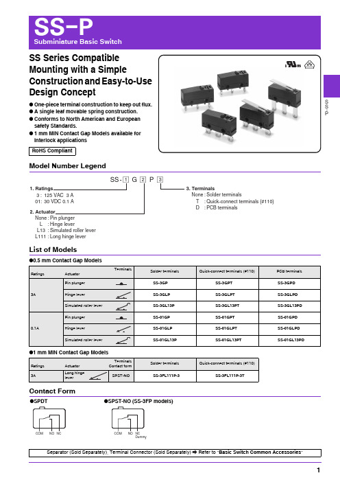
S S -PSS Series Compatible Mounting with a SimpleConstruction and Easy-to-Use Design Concept●One-piece terminal construction to keep out flux. ●A single leaf movable spring construction. ●Conforms to North American and European safety Standards.●1 mm MIN Contact Gap Models available for Interlock applicationsRoHS CompliantModel Number LegendList of Models●0.5 mm Contact Gap Models●1 mm MIN Contact Gap ModelsContact FormSS -@@@1. Ratings3 : 125 VAC 3 A 01 : 30 VDC 0.1 A2. ActuatorNone : Pin plunger L : Hinge leverL13 : Simulated roller lever L111 : Long hinge lever123 3. TerminalsNone : Solder terminalsT : Quick-connect terminals (#110) D : P CB terminalsG P Dummy●SPDT●SPST-NO (SS-3FP models)Separator (Sold Separately), Terminal Connector (Sold Separately)Refer to "Basic Switch Common Accessories "SS-P Subminiature Basic SwitchS S-P Contact Specifications*Please refer to "Using Micro Loads" in "●Precautions" for moreinformation on the minimum applicable load.RatingsNote 1.The above rating values apply under the following test conditions.(1) Ambient temperature: 20±2°C(2) Ambient humidity: 65±5%(3) Operating frequency: 20 operations/minNote 2.Consult your OMRON sales representative for information on modelsfor other loads.Approved Safety StandardsUL (UL1054/CSA C22.2 No.55)VDE (EN61058-1)Testing conditions: 5E4 (50,000 operations) T55 (0 to 55°C) CharacteristicsNote.The data given above are initial values.*1.The values for dielectric strength shown are for models with a Separator (refer to "Micro Switch Common Accessories").*2.The values are at Free Position and Total Travel Position values for pin plunger, and Total Travel Position value for lever.Close or open circuit of the contact is 1 ms max.*3.For testing conditions, consult your OMRON sales representative.Item Model SS-3P models SS-01P models SS-3FP modelsContactSpecification Rivet Crossbar RivetMaterial SilverGoldalloySilverGap(standardvalue)0.5 mm 0.5 mm 1 mm min.InrushcurrentNC9 A max. -9 A max.NOMinimum applicable load(reference value) *5 VDC 160 mA 5 VDC 1 mA 5 VDC 160 mAModelSS-3P /SS-3FP modelsSS-01P modelsRated voltage Item Resistive load125 VAC 3 A 0.1 A30 VDC 3 A 0.1 AModel SS-3P / SS-3FP SS-01PRated voltage Item Resistive load125 VAC 3 A 0.1 A30 VDC 3 A 0.1 ARated voltage Model SS-3P / SS-3FP SS-01P125 VAC 3 A 0.1 A30 VDC 3 A 0.1 AItem Model SS-3P models SS-01P models SS-3FP modelsPermissible operating speed 0.1 mm to 1 m/s (for pin plunger models)PermissibleoperatingfrequencyMechanical 300operations/min Electrical 30operations/min Insulation resistance 100 MΩ min. (at 500 VDC with insulation tester)Contact resistance (initial value) 50 mΩ max. 100 mΩ max. 50 mΩ max.Dielectricstrength *1Between terminals of thesame polarity1,000 VAC 50/60 Hz for 1 minBetween current-carryingmetal parts and ground1,500 VAC 50/60 Hz for 1 minBetween each terminalsand non-current-carryingmetal parts1,500 VAC 50/60 Hz for 1 minVibrationresistance *2Malfunction 10 to 55 Hz, 1.5 mm double amplitudeShockresistanceDurability 1,000m/s2 {approx. 100G} max.Malfunction *2300 m/s2 {approx. 30G} max.Durability *3Mechanical 1,000,000 operations min. (60 operations/min)100,000 operations min.(60 operations/min)Electrical70,000 operations min.(20 operations/min, 125 VAC) 200,000 operations min.(20 operations/min)100,000 operations min.(20 operations/min, 30 VDC)100,000 operations min.(20 operations/min, 30 VDC)Degree of protection IEC IP40Degree of protection against electricshockClass IProof tracking index (PTI) 250Ambient operating temperature -25°C to +85°C (at ambient humidity of 60% max.) (with no icing or condensation)Ambient operating humidity 85% max. (for +5 to +35°C)Weight Approx. 1.6 g (pin plunger models)SS-PSubminiature Basic SwitchS S -PTerminals/Appearances (Unit: mm)Mounting Holes (Unit: mm)Dimensions (Unit: mm) and Operating CharacteristicsThe illustrations and dimensions are for models with solder terminals. Refer to "Terminals/Appearances" for details on models with quick connect terminals (#110) or PCB terminals.Note 1.Unless otherwise specified, a tolerance of ±0.4 mm applies to all dimensions. Note 2.The operating characteristics are for operation in the A direction ().●Solder terminals●Quick Connect Terminals (#110)●PCB terminals<PCB Mounting Dimensions (Reference)>2-2.4 dia. mounting holes ●Pin plunger SS-3GP SS-01GPOperating characteristics Model SS-3GP SS-01GPOperating ForceOF Max. Releasing ForceRFMin.1.50 N {153 gf}0.2 N {20 gf}Pretravel PT Max. Overtravel OT Min. Movement Differential MD Max. 0.6 mm 0.4 mm 0.15 mm Operating PositionOP8.4±0.3 mm●Hinge leverSS-3GLP SS-01GLPOperating characteristics Model SS-3GLP SS-01GLPOperating ForceOF Max.Releasing ForceRFMin.0.5 N {51 gf}0.05 N {5 gf}Overtravel OT Min. Movement Differential MD Max. 1.0 mm 0.8 mmFree PositionFP Max.Operating Position OP13.6 mm 8.8±0.8 mm●Long hinge lever SS-3FL111P-3Operating characteristicsModel SS-3FL111P-3Operating Force OF Max.Releasing Force RFMin.0.55 N {56 gf}0.01 N {1 gf}Overtravel OT Min. Movement Differential MD Max. 1.0 mm 3.0 mm Free PositionFPMax.Operating PositionOP16.8 mm 8.8±1.5 mmSS-PSubminiature Basic SwitchS S -PNote 1.Unless otherwise specified, a tolerance of ±0.4 mm applies to all dimensions. Note 2.The operating characteristics are for operation in the A direction ().Precautions★Please refer to "Common Precautions" for correct use.●Soldering•Connecting to Solder TerminalsComplete the soldering at the iron tip temperature of 350 to 400°C within 5 seconds, and do not apply any external force for 1 minute after soldering. Soldering at an excessively high temperature or soldering for more than 5 seconds may deteriorate the characteristics of the Switch. •Connecting to PCB terminalsWhen using automatic soldering baths, we recommend soldering at 260±5°C within 5 seconds. Make sure that the liquid surface of the solder does not flow over the edge of the board.When soldering terminals manually, complete the soldering at the iron tip temperature between 350 to 400°C within 3 seconds, and do not apply any external force for 1 minute after soldering. When applying solder, keep the solder away from the case of the Switch and do not allow solder or flux to flow into the case.●MountingUse M2.3 mounting screw with plane washers or spring washers to securely mount the Switch. Tighten the screws to a torque of 0.23 to 0.26 N·m {2.3 to 2.7 kgf·cm}.●Using Micro LoadsUsing a model for ordinary loads to open or close the contact of a micro load circuit may result in faulty contact. Use models that operate in the following range. However, even when using micro load models within the following operating range, if inrush current occurs when the contact is opened or closed, it may increase the contact wear and so decrease durability. Therefore, insert a contact protection circuit where necessary. The N-level reference value applies for the minimum applicable load. This value indicates the malfunction reference level for the reliability level of 60% (λ60).(JIS C5003)The equation, λ60=0.5×10⁻⁶/operation indicates that theestimated malfunction rate is less than operations with a reliability level of 60%.●Simulated roller lever SS-3GL13PSS-01GL13POperating characteristicsModel SS-3GL13P SS-01GL13P Operating Force OF Max.Releasing Force RFMin.0.5 N {51 gf}0.05 N {5 gf}Overtravel OT Min. Movement Differential MD Max. 1.0 mm 0.8 mm Free PositionFPMax.Operating PositionOP15.5 mm 10.7±0.8 mmCautionsCorrect Use12,000,000Current (mA)V o l t a g e (V )SS-PSubminiature Basic SwitchS S -P• Application examples provided in this document are for reference only. In actual applications, confirm equipment functions and safety before using the product.• Consult your OMRON representative before using the product under conditions which are not described in the manual or applying the product to nuclear control systems, railroad systems, aviation systems, vehicles, combustion systems, medical equipment, amusement machines, safety equipment, and other systems or equipment that may have a serious influence on lives and property if used improperly. Make sure that the ratings and performance characteristics of the product provide a margin of safety for the system or equipment, and be sure to provide the system or equipment with double safety mechanisms.Cat. No.B108-E1-050716(0207)(O)Note: Do not use this document to operate the Unit.OMRON CorporationElectronic and Mechanical Components CompanyContact: /ecb。


Contents1.Overview (3)2.Product Specification (4)2.1Nomenclature (4)2.2Product Line (4)2.3Compressor specification table (4)2.4Operating range graph (6)3.Construction & Functions (8)3.1Design Features (8)3.2Capacity modulation system (8)3.2.1Step type capacity modulation system (10)3.2.2Stepless type capacity modulation system (14)3.2.3The Location of the Solenoid Valves (19)4.Lubricant (21)4.1Lubricant Specification (21)4.2The Replacement of Lubricant (22)4.3.1Oil Change Schedule (22)4.3.2Pre-cautions for changing oil (22)5.System Application (24)5.1Piping Design (24)5.1.1Suction and Discharge Piping Layout (24)5.1.2Economizer Piping Layout (26)5.1.3Minimum pressure valve (26)5.1.4Liquid Line Filter Dryer (27)5.1.5Sight Glass with Moisture Indicator (27)5.2Oil Line (28)5.2.1Oil Supply (28)5.2.2Lubrication and Capacity Control Modulation (28)5.2.3Compressor chamber injection system (28)5.2.4Protection in Oil Circuit (29)1)Oil temperature (29)2)Oil filter (30)3)Oil pressure differential (31)4)Oil level protection (31)5.2.5Oil cooling system (31)1)Air cooling type (33)2)Water cooling type (33)3)Refrigerant oil cooling (34)5.3Motor Liquid Injection Cooling (34)5.4Economizer System (35)5.4.1Economizer System with Sub Cooler (35)5.4.2Economizer System with Flash Type Subcooler (36)5.5Recommended System Layout (38)Figure 5-14. High Temperature Heat Pump Recommend System Layout (38)6.Electrical Design (39)6.1Electrical parameters and design (39)6.1.1Y-Δ Start (39)6.1.2Power requirements (40)6.1.3MCC&LRA (41)pressor Installation (45)7.1Open compressor wooden crate (45)7.2Compressor Lifting (45)7.3Compressor installation (46)8.Operation and Maintenance (48)8.1Compressor commissioning check (48)1.1.1Check list before Start (48)8.1.2Check list during operation (49)8.2rouble shooting table (50)9.Dimensions (53)10.Accessories (60)10.1Accessory List (60)10.2Accessory for gas refrigerant line (61)10.2.1Shut-off valve (61)10.2.2Tube (62)10.2.3Check valve (64)10.2.4Minimum pressure valve (66)10.3Oil line accessory (68)10.3.1Oil flow switch (68)10.3.2Oil Line Solenoid Valve (70)10.3.3Oil Pressure Differential Switch (70)10.4Electrical Accessory (71)10.4.1INT69 HBY Diagnose Protection module (71)10.4.2300Woil heater (74)10.5Other accessories (77)10.5.1Cushion (77)1.OverviewFor conventional single-stage screw compressors, Its evaporation temperature can only reach -40~-50°C during freezing application. If you want to break this application limitation, it is required to use two-stage compressor or cascade system. Meanwhile, the working condition of high pressure ratio brings problems to the traditional single-stage compressors during compression process, such as excessive gas leakage and high exhaust temperature etc., which leads to low efficiency and poor reliability when it is working is such harsh conditions.The compound two-stage compressor well solves above problems. Compared with the two-stage compressors or cascade system, the compund two-stage compressors occupy less space and the system is easy to control, so it's more efficiency and reliable.LT Series compound two-stage compressor’s evaporation temperature can be as low as -60~-65°C , Its full load evaporating temperature can be -25°C, LT-S-L Series compound two-stage low temperature compressor is based on the LT-S series which modified the internal structure and optimized the motor matching to increase the compressor full-load evaporation temperature to -10 °C, So that LT-S-L series can meet the requirements of industrial refrigeration、quick freezing tunnel and freezing library without pre-coolingFor above reasons, Therefore The Shanghai Hanbell Precise Machinery Co., Ltd. developed the LT series high temperature compressors. High efficiency and reliability under big pressure differential and compression ratio working condition is the main demand in designing. It is a elitist product which accumulates Shanghai Hanbell's rich technology and extensive application experience. It can be widely used in many industries such as high temperature hot water, central heating and so on.2. Product Specification2.1 NomenclatureTable 2-1.LT series low temperature compressor nomenclature 2.2 Product LineTable 2-2.LT low temperature series product specification★2.3 Compressor specification tableTable 2-3.LT series compressor specification2.4Operating range graph图2-1. R22运行范围图图2-2.R404A运行范围图3.Construction & Functions3.1Design Features1)Starting loadStarting with light load; its starting load is similar to ordinary single stage compressor, so as to avoid greater impact on power grid.2)Motor cooling channelExcellent motor cooling channel design which ensures the high efficiency of the compressor, while realizing the reliable cooling of the motor, so that the compressor can operate in a very wide range, and a more extensive scope of application.3)integrated design of system partsPre-installed medium pressure check valves, shut off valves and economizer filters that ensure reliable protection of compressors and simplify customer system configuration.4)Motor temperature visualizationThe embedded temperature sensor of motor, PT100, PT1000 and NTC, are optional, which can directly read the motor temperature to control the motor temperature.3.2Capacity modulation systemLT series screw compressor is equipped with 3/4 step capacity modulation system or continuous (stepless) capacity modulation system.Both of the two capacity modulation systems are composed of slide valve, piston rod, piston cylinder and piston. As shown in Figure 3-1 below.When the spool is fully in contact with the suction side, the screw rotor is in full-load suction state, at which time the working volume of the compressor is maximized. As the spool is separated from the suction side, it moves toward the exhaust side. A bypass cavity is formed between the slider and the suction side.Its presence causes the compressed gas in this range to be bypassed directly to the low pressure, and the actual suction volume of the screw rotor is reduced.The more the slide valve moves toward the exhaust side, the smaller the actual suction volume of the compressor will be.And the system cooling capacity will also reduce The slide valve is driven by the pressure differential among the internal capacity modulation system.The lubricant comes from the external oil separator and passes through the oil filter then enters into the oil inlet port of the compressor, and at last divided to bothsides of the piston. As a result, the piston can be controlled by discharging the high pressure lubricant at one side to low pressure, letting it flow to the low pressure side so that the slide valve will move with the piston to realize the loading and unloading of the compressor.The purpose of the piston spring is to push the piston to its initial position (min. load position), so as to realize the automatic unloading start. It not only reduces the mechanical impact on the compressor's moving parts, but also reduces the electrical current during compressor start up.Stepless capacity control, solenoid valve(SV1:unloading, SV3:50%, SV5:100%) is controlled by a micro controller or a thermal switch to adjust the piston smoothly to stably control cold output. If the oil filter capillary or solenoid valve of the capacity modulation system don't work properly, it will cause the capacity modulation system to be abnormal and fail.Figure 3-1.Capacity Modulation System3.2.1 Step type capacity modulation system1) Step type control logicY: Energize the solenoid valve N: Do not energize the solenoid valveTable 3-1. Step Type Capacity Modulation Control Logic2) Step type capacity modulation graphFigure 3-2. Step Type Capacity Modulation3)Step type control logic description10% loadFigure 3-3. 10% LoadWhen starting up thecompressor, SV1(unload) &SV2 (10%) need to beenergized to make the pistonkeep at the 10% position(leftside)In this state, the highpressure oil passes throughSV1(unload) then goes to theright side of the piston. At thesame time, the oil from left side of the piston passes through SV2 (10%) then discharge to the low pressure side. By doing so, the piston can be held at the 10% load position.★ Note: 10% load is for start up only. Running the compressor at 10% load for a long time is not recommended.50% loadAt this time, the capacity adjustment solenoid valves SV1 (unload) and SV3 (50%) are active.Under 50% load, SV1(unload) &SV3 (50%) are energized.In this state, the high pressure oil passes to the left side of the piston continuously. At the same time, the oil passes through SV1 (unload) then goes to the right side of the piston.If the piston is at the left side of the 50% hole (the loading is less than 50%), the oil at the right side of the piston will pass through SV3 (50%) and discharge to the low pressure side then the piston will move to right side until the position blocks the 50% hole. Thus the compressor is loaded to 50% smoothly.Vice versa, if the piston is at the right side of the 50% hole (the loading is more than 50%), the oil in the left side of the piston will pass through SV3 (50%) and go out to the low pressure side then the piston will move to left until the position blocks the 50% hole. Thus the compressor is loaded to 50% smoothly.75% LoadUnder 75% load, SV1(unload)&SV4 (75%)are energized.The logic of 75% load issimilar to that of 50%. Thepiston can be held around75% position by 75% holeto make the compressorrun under 75% load.Figure 3-5.75% Load100%LoadUnder 100% load, SV5(100%) is energized. In this state,the high pressure oil passes to theleft side of the piston continuously.At the same time, the oil in theright side of the piston passesthrough SV5 (100%) then goes tothe low pressure side to make thepiston be held at 100% position.fig3-6.100% Load4) Step type capacity modulation and water temperature controlFigure 3-7.Step type capacity modulation and water temperature control★Note: T & T' should be adjusted by system designer’s experience and practical application.Time启动Set point + 2TSet point + TSet pointSet point – T'Storage temperaturet1 t21~3min 60~90 sec3.2.2Stepless type capacity modulation systemStepless type is suitable when the refrigeration system needs to achieve precise control of cooling capacity.1)Stepless type control logicTable 3-2. Stepless Type Capacity Modulation Control Logic 50%~100%2)Stepless type capacity modulation graphFigure 3-8.Stepless Type Capacity Modulation3)Stepless type control logic descriptionIn stepless type capacity modulation system, the oil keeps going to the left side of the piston. The oil bypass in the left side of the piston is controlled by SV3 (50%). The oil inlet in the right side of the piston is controlled by SV1 (unload) and oil bypass in the right side of the piston is controlled by SV5 (100%). These three solenoid valves are controlled by temperature controller or PLC.Through the three solenoid valves, the cooling capacity can be controlled at any position from 50%~100%, so through periodical adjustment of SV1、SV3、SV5, the energy output can controlled stably.★Note: SV2(10%) can only be used for machine start and stop. Don't run the machine at 10% load for long time once the machine is started. It shall be switched to load model directly.The stepless type capacity modulation system shall be connected to the micro controller(optional), eg. PLC etc. in order to control the system at the target working condition.LoadDuring load process, the SV5 (100%) adopts pulse activating, and the rest solenoid valve are not energized.In this kind ofsituation, the highpressure oil goes into theleft side of the pistoncontinuously and the oilin the right side of thepiston bypasses throughSV5 (100%) to the lowpressure side.The piston willcontinue to move to theright side and thecompressor completeload process.Figure 3-9. LoadUnloadDuring unload process,the SV2(50%) stays active,and SV1 (unload) adopts pulseactivating, and the restsolenoid valve are notenergized.The high pressure oilcontinues to go to the left sideof the piston and goes into theright side of the piston passingthrough SV1(unload).Through SV3(50%), it Figure 3-10. Unload bypasses to the low pressure side, so that the piston continues to move to the left side, and the compressor will load to 50% piston.Keep load stateFigure 3-11. Keep Load StateDuring this process, all S/V are not energized. The high pressure oil coming continues to go to the left side of the piston. The left side oil inlet of the piston SV1(unload) and SV5(100%) are closed to keep the oil amount in the right side of the piston. The piston will not be able to move and stay at its original position, so that the compressor capacity will not change as well.Stepless type capacity modulation and water temperature controlBelow picture shows the load control of single compressor in the application of stepless type capacity modulation.Figure 3-12. Stepless Type Capacity Modulation★Note :X ′Upper Limit ;X 〞Lower Limit ;X Set Point ;H Control Range ;Y Actual valve❆ Description:● The actual water temperature exceeds the upper limit between A & B. Itmeans the compressor ought to unload until the actual value is within the control range.● The real value is smaller than the bottom line between C & D. It means therequired cooling capacity is decreasing and the compressor needs to be unloaded until the real value returns to the control range.Figure 3-13. Solenoid Valve Action Intervals-Stepless Type★Note :For detail stepless type capacity modulation control logic, please refer toTable 3-2Load/Unload functions between A and B, C and D.Energized :Solenoid valve is powered and energized Close : Solenoid valve is not energized T1,T3:Pulse time 0.5~1.5 seconds T2,T4:Pause time 10~20 secondsTime3.2.3The Location of the Solenoid Valves1)LT-83/41<-65/32Figure 3-14.LT-83/41<-65/32 solenoid valve location2)LT-20/10<-30/12<-45/20<-55/25Figure 3-15.LT-20/10<-30/12<-45/20<-55/25 Solenoid Valve Location3)Compressor unloading for startup, and stopTo decrease the mechanical loading to compressor’s parts and decrease the starting current during start up. Hanbell designs for LT compressor the function of unloading startup. To ensure compressor loads steadily, please follow Figure 3-16 to load step by step during the whole loading process.When compressor is about to shut down, it is also required to unload to ensure that the slide valve is at lowest loading position during next startup and compressor could have an unloading startup. Thus Hanbell requires no matter what load condition of the compressor is, it should be unloaded step by step till minimum load before stop according to below Figure 3-16.Figure 3-16. Compressor Startup and Stop ProcessCaution:1)A fter startup, keep the minimum load for 10 seconds. Before shut down, keep the minimum load for 30 seconds(Time can be set to 10~60seconds).2)A fter startup, when the pressure difference between high pressure and middle pressure is less than 3.5bar, the compressor shall be run at 10% load at low pressure stage. Don't load and open ECO.3)t=30 seconds(Time can be set to 30~60seconds).4)A fter the compressor shut down, the SV1 (unload) & SV2(10%) need to be still energized for 3 minutes, so as to ensure the compressor can still at min load position at next startup.5)H anbell strongly recommends that the compressor start-up and shutdown control logic shall refer to above graph. For detail informationplease refer to the regulations written in LT-S Control Requirements.4.LubricantTable 4-1. Lubricant SpecificationCaution:1)P lease refer to the table above to select the suitable lubricant and refrigerant and its operation range need to be taken into consideration as well.2)H anbell strongly recommends do not use the lubricant which isn’t certified by Hanbell since it may damage the compressor seriously.3)T his specification table is for LT series compressors only.4)T he oil temperature at the point when the compressor starts is suggested to be 5K higher than the corresponding saturation temperature of the oil separator in order to avoid too much oil containing in the refrigerant which may affect the lubricant. 5)A fter compressor stops, please turn on the oil heater of the external oil separator.If the compressor shuts down for a long time, please turn off the oil heater. Please heat the lubricant for more than 2 hours before next start up.1)B e sure to make the system clean and no welding spatter and other impurities before lubricant filling2)I n order to ensure that the system is dry enough, it should be dehumidified before filling. It is advisable to fill the system with dry nitrogen first and then vacuum the system. The vacuum time should be as long as possible. It is strongly recommended to repeat the above steps several times to minimize the water contained in the system.Caution1)D o not use the lubricant which is not approved by Hanbell, otherwise it may causeserious damage to the compressor2)D o not mix different brands of lubricants, otherwise they may cause serious damage to the compressor. Pay attention to it when replacing lubricating oil for the system.4.2The Replacement of Lubricant4.3.1Oil Change Schedule1)C heck lubricant every 10,000 hours after continuous running. For the first operation of the compressor, it is recommended to change the oil and clean the external oil filter after running 2,000 hours. Check the system whether clean or not and then change oil every 20,000 hours or after 4 years continuous running if the system operates in good condition.2)T he oil will deteriorate if the compressor runs at high discharging temperature (above 95℃) in the long term. Please avoid this situation, but if it’s necessary to run in this condition, please shorten the intervals of oil changing.4.3.2Pre-cautions for changing oil1)I t is recommended to check the quality of oil periodically in order to maintain the lubrication performance.2)T he lubricant absorbs moisture in the air. Avoid to expose it to the air for a long timeIf the compressor motor is burned, the acid and harmful substances and burned debris will be brought into the system. Therefore, the oil filters and lubricants must be replaced repeatedly. It is suggested to replace the lubricating oil again after 72 hours of operation until the quality of the lubricating oil in the system returns to standard valve.3)T he foreign body in the oil will block the oil line, so it is necessary to install an oil filter in the external oil line. Also, the pressure differential sensor need to be installed before and after the oil filter. If the pressure differential valve between these two sensors reaches 1.5 bar, the oil filter need to be changed.4)T he acidity of oil will directly affect the life of the motor, and it is recommended to change the oil when PH≤6. (Please also change the filter drier at the same time to make sure the system is dry.)5)I t is important to replace the oil, especially when the motor is burnt because the acidity remains in the system. By replacing the oil can help check the status of thesystem. Check the acidity of the lubricant, and re-change the oil after the system runs for 72 hours until the acidity of the lubricant reaches the standard valve.6)I n case of motor burned out, please not only change the compressor, but also change the oil and check the condition of the oil periodically. If the acidity excesses the standard, please change it immediately and always be aware of the cleanliness and moisture contained in the system.5. System Application★Note :Please consult Hanbell for parallel application and heat pump application.5.1 Piping Design5.1.1 Suction and Discharge Piping Layout1)Material and structure of suction and discharge pipeThe vibration of the compressor is small in normal operation, so it is not necessary to use flexible joints for suction and discharge tubes, but the pipes need to have enough flexible length to ensure the suction and discharge pipes won't cause any stress to the compressor. It is recommended to use copper tube for the suction and discharge piping in order to decrease the piping vibration when the compressor is in operation.2)The dimensions of suction and discharge piping:It is suggested to design the dimension of suction and discharge piping according to Hanbell recommendation (refer to 10.2.2).3)Piping for parallel systemTo improve the system operation efficiency, it’s necessary to reduce the gas -flow resistance and consider the oil return of suction piping. The recommended piping of suction and discharge side for parallel system is shown below:Be aware of the area of the main pipe should not be less than the area of the other pipes to make sure the pressure drops could be controlled in reasonable range. ❆ Piping at discharge side❆ x x xFigure 5-2 Suction Piping for Parallel SystemDetail Drawing 2 4) Suction filterThis model of compressor has a built-in suction filter, but it is only used as a final protection. It should not be used as an suction filter that needs to be cleaned regularly.So It is necessary to install a suction filter (25μm) which is easy to remove and clean it regularly.When the system is first used, it may need to be cleaned up frequently. If the pressure drop is bigger than 0.5 bar, the filter element should be replaced or cleaned until the system is clean. When the filter is disassembled, if the filter is found to be damaged, it needs to be replaced in time, and the impurities in the pipeline should be cleaned up. Ensure that the filter is oriented correctly during installation and it is recommended to add a shut-off valve at the inlet and outlet for easy maintenance.Hanbell The recommended suction filter design is shown in Figure 5-3 below.Figure 5-3.suction filterx xx Detail Drawing 2★Note:External suction filter should be used for cryogenic refrigeration systems。

2007-11-011TOSHIBA Diode Silicon Epitaxial Planar Type1SV323TCXO/VCO• High capacitance ratio: C 1 V /C 4 V = 4.3 (typ.)• Low series resistance: r s = 0.4 Ω (typ.)• Useful for small size tuner.Absolute Maximum Ratings (Ta = 25°C) Characteristics Symbol RatingUnitReverse voltageV R 10 V Junction temperatureT j 125 °C Storage temperature range T stg −55~125 °CNote: Using continuously under heavy loads (e.g. the application of hightemperature/current/voltage and the significant change intemperature, etc.) may cause this product to decrease in thereliability significantly even if the operating conditions (i.e.operating temperature/current/voltage, etc.) are within theabsolute maximum ratings.Please design the appropriate reliability upon reviewing theToshiba Semiconductor Reliability Handbook (“HandlingPrecautions”/“Derating Concept and Methods”) and individualreliability data (i.e. reliability test report and estimated failure rate,etc).Electrical Characteristics (Ta = 25°C)Characteristics Symbol Test Condition Min Typ. Max UnitReverse voltageV R I R = 1 μA 10 ⎯ ⎯ V Reverse current I R V R = 10 V⎯ ⎯ 3 nA Capacitance C 1 V V R = 1 V, f = 1 MHz26.5 ⎯ 29.5pF Capacitance C 4 VV R = 4 V, f = 1 MHz 6.0 ⎯ 7.1 pF Capacitance ratioC 1 V /C 4 V ⎯ 4.0 4.3 ⎯ ⎯ Series resistance r s V R = 4 V, f = 100 MHz ⎯ 0.4 0.8 Ω Note: Signal level when capacitance is measured: Vsig = 500 mVrmsMarkingUnit: mm JEDEC ― JEITA ― TOSHIBA 1-1G1A Weight: 0.0014 g (typ.)/2007-11-012h t t p ://o n e i c .c o m /2007-11-013RESTRICTIONS ON PRODUCT USE• Toshiba Corporation, and its subsidiaries and affiliates (collectively “TOSHIBA”), reserve the right to make changes to the information in this document, and related hardware, software and systems (collectively “Product”) without notice.• This document and any information herein may not be reproduced without prior written permission from TOSHIBA. Even with TOSHIBA’s written permission, reproduction is permissible only if reproduction is without alteration/omission.• Though TOSHIBA works continually to improve Product’s quality and reliability, Product can malfunction or fail. Customers areresponsible for complying with safety standards and for providing adequate designs and safeguards for their hardware, software and systems which minimize risk and avoid situations in which a malfunction or failure of Product could cause loss of human life, bodily injury or damage to property, including data loss or corruption. Before creating and producing designs and using, customers must also refer to and comply with (a) the latest versions of all relevant TOSHIBA information, including without limitation, this document, the specifications, the data sheets and application notes for Product and the precautions and conditions set forth in the “TOSHIBA Semiconductor Reliability Handbook” and (b) the instructions for the application that Product will be used with or for. Customers are solely responsible for all aspects of their own product design or applications, including but not limited to (a) determining theappropriateness of the use of this Product in such design or applications; (b) evaluating and determining the applicability of any information contained in this document, or in charts, diagrams, programs, algorithms, sample application circuits, or any other referenced documents; and (c) validating all operating parameters for such designs and applications. TOSHIBA ASSUMES NO LIABILITY FOR CUSTOMERS’ PRODUCT DESIGN OR APPLICATIONS.• Product is intended for use in general electronics applications (e.g., computers, personal equipment, office equipment, measuring equipment, industrial robots and home electronics appliances) or for specific applications as expressly stated in this document. Product is neither intended nor warranted for use in equipment or systems that require extraordinarily high levels of quality and/or reliability and/or a malfunction or failure of which may cause loss of human life, bodily injury, serious property damage or serious public impact (“Unintended Use”). Unintended Use includes, without limitation, equipment used in nuclear facilities, equipment used in the aerospace industry, medical equipment, equipment used for automobiles, trains, ships and other transportation, traffic signaling equipment, equipment used to control combustions or explosions, safety devices, elevators and escalators, devices related to electric power, and equipment used in finance-related fields. Do not use Product for Unintended Use unless specifically permitted in this document.• Do not disassemble, analyze, reverse-engineer, alter, modify, translate or copy Product, whether in whole or in part.• Product shall not be used for or incorporated into any products or systems whose manufacture, use, or sale is prohibited under any applicable laws or regulations.• The information contained herein is presented only as guidance for Product use. No responsibility is assumed by TOSHIBA for any infringement of patents or any other intellectual property rights of third parties that may result from the use of Product. No license to any intellectual property right is granted by this document, whether express or implied, by estoppel or otherwise.• ABSENT A WRITTEN SIGNED AGREEMENT, EXCEPT AS PROVIDED IN THE RELEVANT TERMS AND CONDITIONS OF SALE FOR PRODUCT, AND TO THE MAXIMUM EXTENT ALLOWABLE BY LAW, TOSHIBA (1) ASSUMES NO LIABILITYWHATSOEVER, INCLUDING WITHOUT LIMITATION, INDIRECT, CONSEQUENTIAL, SPECIAL, OR INCIDENTAL DAMAGES OR LOSS, INCLUDING WITHOUT LIMITATION, LOSS OF PROFITS, LOSS OF OPPORTUNITIES, BUSINESS INTERRUPTION AND LOSS OF DATA, AND (2) DISCLAIMS ANY AND ALL EXPRESS OR IMPLIED WARRANTIES AND CONDITIONS RELATED TO SALE, USE OF PRODUCT, OR INFORMATION, INCLUDING WARRANTIES OR CONDITIONS OF MERCHANTABILITY, FITNESS FOR A PARTICULAR PURPOSE, ACCURACY OF INFORMATION, OR NONINFRINGEMENT.• Do not use or otherwise make available Product or related software or technology for any military purposes, including without limitation, for the design, development, use, stockpiling or manufacturing of nuclear, chemical, or biological weapons or missile technology products (mass destruction weapons). Product and related software and technology may be controlled under theJapanese Foreign Exchange and Foreign Trade Law and the U.S. Export Administration Regulations. Export and re-export of Product or related software or technology are strictly prohibited except in compliance with all applicable export laws and regulations.• Please contact your TOSHIBA sales representative for details as to environmental matters such as the RoHS compatibility of Product. Please use Product in compliance with all applicable laws and regulations that regulate the inclusion or use of controlled substances, including without limitation, the EU RoHS Directive. TOSHIBA assumes no liability for damages or losses occurring as a result of noncompliance with applicable laws and regulations./分销商库存信息: TOSHIBA1SV323(TPH3,F)。

R e l e a s e d a t e : 2017-02-13 13:30D a t e o f i s s u e : 2017-02-13202091_e n g .x m lRefer to “General Notes Relating to Pepperl+Fuchs Product Information”.R e l e a s e d a t e : 2017-02-13 13:30D a t e o f i s s u e : 2017-02-13202091_e n g .x m lRefer to “General Notes Relating to Pepperl+Fuchs Product Information”.Technical dataGeneral specifications Effective detection range 0.4 ... 8 m Light source IREDLight typemodulated infrared light , 850 nm Protection field height see Table 1, max. 1200 mmOperating mode Startup/restart disable, deactivateable Optical resolution 14 mm Angle of divergence 5 °Ambient light limit Not sensitive to ambient light in accordance with EN 61496-2UL File NumberE215245Functional safety related parameters Safety Integrity Level (SIL) SIL 3Performance level (PL) PL e Category Cat. 4Mission Time (T M ) 20 a PFH d Depending on the protection field height; see Manual Type 4Indicators/operating means Operation indicator green: Power onFunction indicator Green: OSSD ON , Red: OSSD OFFStatus indicator Transmitter unit: LED yellow: Mode, test or errorReceiver: LED yellow: Start readiness, function reserve or errorElectrical specifications Operating voltageU B 24 V DC (-20%, +30%) ; Power supply with safe isolation: 24 V DC No-load supply current I 0Transmitter unit:≤ 150 mAReceiver: ≤ 150 mA (without outputs)Protection class III , IEC 61140Power consumptionP 0Transmitter unit: 5 W Receiver: 15 W Input 1Input type Transmitter unit test Input formatBreak contact Switching voltage 24 V DC Input current 5 mAInput 2Input type Transmitter unit, mode A/B Function Beam Code A: open or 0 V Beam Code B: 24 V DC, 5 mA Input 3Input type Receiver unit relay monitor Input formatBreak contact Switching voltage 24 V DC Input current 5 mAInput 4Input type Receiver unit, start release Input format Break contact Input current 5 mAInput 5Input type Receiver unit, mode A/B (see transmitter unit, mode A/B)OutputResponse time see Table 1, max. 54 msOutput 1Output type Receiver unit OSSDSignal output PNP semiconductor , monitored for short and cross circuits Switching voltage ON: U B - 2 V; OFF: < 1 V Switching current ON: max. 0.1 A; OFF: < 5 µAOutput 2Output type Receiver signal output start readinessSignal output PNP-semiconductor, short-circuit protected, 0.1A Ambient conditions Ambient temperature -30 ... 60 °C (-22 ... 140 °F)Storage temperature -30 ... 70 °C (-22 ... 158 °F)Relative humidity max. 95 %, not condensingMechanical specifications Housing length L see table 2Degree of protection IP65 , For indoor use onlyConnectionTransmitter unit: 4-pin, M12 x 1 connector Receiver: 8-pin, M12 x 1 connector Cable cross section min. 0.25 mm 2 Max. cable length 50mMaterialHousing extruded aluminum section , gold anodized Optical facePlastic pane , Transparent polycarbonateR e l e a s e d a t e : 2017-02-13 13:30D a t e o f i s s u e : 2017-02-13202091_e n g .x mlRefer to “General Notes Relating to Pepperl+Fuchs Product Information”.Table 1 - Response time:Table 2 - Total length and weight:Mounting aid OMH-SLCT-01Press & Release q u ick clamp and adj u stment systemOMH-SLCT-02Attachment aid for Press &Release q u ick clamp and adj u stment systemOMH-SLCT-03Mo u nting aid w ith fixed bearing (long) for mo u nting or u sed to connect 2 light gids OMH-SLCT-04Mo u nting aid w ith loose bearing (narro w )Other accessories TR 14/30/50/60Test rod for 14mm, 30mm, 50mm or 60mm resol u tionAA SLCT-01Alignment aid (box le v el to snapped into the lateral groo v es), Angle error: < 1°Masssee table 2Compliance with standards and directi-vesDirective conformity CE Machinery Directive 2006/42/EC EN ISO 13849-1:2008 ; EN 61496-1:2013EMC Directive 2004/108/EC EN 61000-6-3:2007+A1:2010 ; EN 61000-6-4:2007+A1:2011Standard conformity Functional safety IEC 61508:2010 part 1-4Standards IEC 61496-2:2013Approvals and certificates CE conformity CEUL approval cULus ListedCCC approval CCC approval / marking not required for products rated ≤36 V TÜV approvalTÜVAdditional informationHeight of the protected area[mm]Response time[ms]100112001530019400235002660030700348003890042100046110050120054Height of the protected area[mm]Total length oftransmitter/recei v er u nit[mm]Weight oftransmitter/recei v er u nit[g]1002191402003192003004192504005193105006193706007194307008194808009195409001019600100011196501100121971012001319760System accessoriesR e l e a s e d a t e : 2017-02-13 13:30D a t e o f i s s u e : 2017-02-13202091_e n g .x m lRefer to “General Notes Relating to Pepperl+Fuchs Product Information”.V1-G-BK2M-PUR-U:Cable, M12, 4-pin, 2m, UL-connector V1-G-BK5M-PUR-U:Cable, M12, 4-pin, 5m, UL-connector V1-G-BK10M-PUR-U:Cable, M12, 4-pin, 10m, UL-connector V19-G-BK2M-PUR-U:Cable, M12, 8-pin, 2m, UL-connector V19-G-BK5M-PUR-U:Cable, M12, 8-pin, 5m, UL-connector V19-G-BK10M-PUR-U:Cable, M12, 8-pin, 10m, UL-connector。

安徽富信半导体科技有限公司ANHUI FOSAN SEMICONDUCTOR TECHNOLOGY CO.,LTD.SS115-SS120SMA Schottky Barrier Rectifier Diode肖特基势垒整流二极管■Features 特点Low forward voltage drop 低正向压降High current capability 高电流能力Surface mount device 表面贴装器件Case 封装:SMA(DO-214AC)■Maximum Rating 最大额定值(T A =25℃unless otherwise noted 如无特殊说明,温度为25℃)Characteristic 特性参数Symbol 符号SS115SS120Unit 单位Peak Reverse Voltage 反向峰值电压V RRM 150200V DC Reverse Voltage 直流反向电压V R 150200V RMS Reverse Voltage 反向电压均方根值V R(RMS)105140V Forward Rectified Current 正向整流电流I F 1A Peak Surge Current 峰值浪涌电流I FSM 30AThermal Resistance J-A 结到环境热阻R θJA 50℃/WJunction Temperature 结温T J 150℃Storage Temperature 储藏温度T stg-65to+150℃℃■Electrical Characteristics 电特性(T A =25℃unless otherwise noted 如无特殊说明,温度为25℃)Characteristic 特性参数Symbol 符号SS115SS120Unit 单位Condition 条件Forward Voltage 正向电压V F 0.92V I F =1A Reverse Current 反向电流I R (25℃)(100℃)0.0510mA V R =V RRM Diode Capacitance 二极管电容C D110pFV R =4V,f=1MHzANHUI FOSAN SEMICONDUCTOR TECHNOLOGY CO.,LTD.SS115-SS120■Typical Characteristic Curve典型特性曲线ANHUI FOSAN SEMICONDUCTOR TECHNOLOGY CO.,LTD.SS115-SS120■Dimension外形封装尺寸。

H40-60XT SERIESTECHNICAL GUIDE15151011372235C38E7XWDT HEAD CLEARANCESEE CHART 182019H40-50XT 44.4 (1129)H60XT 45.2 (1149)17b 2116Circled dimensions correspond to the line numbers on the tabulated chart inside the Technical Guide. Dimensions are in inches (mm).DIMENSIONS151011372235C 38E 7XWDTHEAD CLEARANCESEE CHART182019H40-50XT 44.4 (1129)H60XT 45.2 (1149)17a17b2116TRUCKMODEL C D E TW X in (mm)percentpercentin (mm)in (mm)in (mm)H40XT 17.1 (434)7053 6.6 (168)13.7 (349)27.6 (702)H50XT 19.5 (495)5553 6.6 (168)13.7 (349)27.6 (702)H60XT20.4 (518)58587.4 (168)14.5 (369)28.4 (722)HEAD CLEARANCESeat TypeStandard OHG*Optional OHG*Non-Suspension 46.9 (1192)43.0 (1092)36.9 (939)Full-Suspension46.9 (1192)N/AN/A* Seat in depressed position* This model may be equipped with an optional load weight system with an auxiliary display. The system must be calibrated for best results. The mast must be vertical and the forks at 350mm (14”). If these procedures are met the weight indicated on the display will be +/- 8%.CERTIFICATION: Hyster lift trucks meet the design and construction requirements of B56.1-1969, per OSHA Section 1910.178(a)(2), and also comply with the B56.1 revision in effect at time of manufacture. Certification of compliance with the applicable ANSI standards appears on the lift truck.Performance specifications / ratings are for truck equipped as described under Standard Equipment in this Technical Guide. Performance specifications are affected by the condition of the vehicle and how it is equipped, as well as by the nature and condition of the operating area. Specifications are subject to change and the proposed application should be discussed with your authorized Hyster Company Dealer.Limited by traction. For further information on this dimension, please contact your local Hyster ® dealer.G E N E R A L1Manufacturer Name Hyster Company 2Model H40XT*H50XT*H60XT*EnginePSI 2.4L 3Rated Capacitylb (kg)4000 (1814)5000 (2268)6000 (2722)4Load Center, Distance in (mm)24 (610)5Power Type - LPG, Dual Fuel LPGDual FuelLPG Dual FuelLPGDual Fuel6Operator Type Sit-Down Rider7Step Heightin (mm)16.3 (415)17.1 (435)8Tire Type - Cushion, Solid, Pneumatic Pneumatic 9Wheels, Number - Front/ Rear 2x/2D I ME N S I O N S 10Lift Height, Top of Fork (TOF)in (mm)129 (3292)126 (3209)11Lift Heights, Standard Limited Free Lift (LFL) w/LBR (TOF)in (mm) 5 (140)Lift Heights, Optional Full Free Lift (FFL) with LBR (TOF)in (mm)58 (1490)12Standard Carriage Widthin (mm)42 (1067)13Forks, Thickness x Width x Length in (mm) 1.6 X 3.9 X 42 (40 X 100 X 1067)15Mast Tilt Angles, Forward/Backward degrees 6/616Length To Face of Forksin (mm)99.5 (2528)101.9 (2589)106.3 (2701)17a Overall Width, Standard Tread in (mm)45.7 (1162)46.9 (1191)17b Overall Width, Wide Treadin (mm)52 (1322)52.2 (1326)18Height, Standard Mast - Loweredin (mm)86 (2170)89 (2245)19Height, Standard Mast - Extended with LBRin (mm)147 (3715)175 (4330)Height, Standard Mast - Extended without LBR in (mm)154 (3904)154 (3905)20Height, Standard Overhead Guardin (mm)87.7 (2228)88.6 (2250)Height, Optional Overhead Guard in (mm)83.8 (2128)84.6 (2150)21Turning Radius, Minimum Outside (OTR)in (mm)85.7 (2178)88 (2236)91.5 (2324)22Length, Center of Wheel to Face of Forksin (mm)18.5 (471)19 (483)23Aisle Width, Right Angle Stack (Add Length of Load) in (mm)104.3 (2649)106.6 (2707)110.3 (2802)24Equal Aisle, 90-Degree Intersecting Aisle in (mm)79.9 (2030)80.9 (2056)83 (2108)P E R F O R M A N C E25Travel Speed, Powershift Transmission RL/NL mph (km/h)11.4/11.6 (18.4/18.6)12.3/12.4 (19.8/20)26Lift Speed, Standard 2-Stage LFL RL/NLft/min (m/s)128/134 (0.65/0.68)112/118 (0.57/0.60)Lift Speed, Optional 3-Stage FFL RL/NLft/min (m/s)120/126 (0.61/0.64)106/112 (0.54/0.57)27Lowering Speed, Standard 2-Stage LFL RL/NLft/min (m/s)114/98 (0.58/0.50)Lowering Speed, Optional 3-Stage FFL RL/NL ft/min (m/s)114/98 (0.58/0.50)28Maximum drawbar pull RL/NLlb (kg)4947/2282 (2244/1035)4916/2217 (2230/1006)4438/2534 (2013/1149)Drawbar Pull, Standard Transmission @ 1 mph RL/NL lb (kg)4186/2282 (1899/1035)4154/2217 (1884/1006)3792/2534 (1720/1149)29Gradeability, Standard Transmission @ 1 mph RL/NL Percent 35.9/31.530.2/27.623.5/27.6W T .31Weight, Standard Truck (2-Stg. LFL 84/127) NLlb (kg)8170 (3705)8910 (4040)10300 (4671)Weight, Standard Truck (2-Stg. LFL 84/127) RL lb (kg)12170 (5520)13910 (6308)16300 (7392)32Axle Loading, Static Front/Rear NLlb (kg)3855/4311 (1748/1955)3695/5210 (1676/2363)4207/6089 (1908/2761)Axle Loading, Static Front/Rear RL lb (kg)10518/1648 (4770/747)12024/1881 (5453/853)14064/2232 (6378/1012)T I R E S & W H E E L S33Tire Size, Front 7.00 x 12 - 1228 x 9 - 1534Tire Size, Rear 6.00 x 9 6.50 x 1035Wheelbasein (mm) 63.9 (1623)66.9 (1700)37Ground Clearance, Lowest Point NL (w/RL subtract-6mm)in (mm) 3.3 (84) 4.1 (104)38Ground Clearance, Center of Wheelbase NL in (mm)7.5 (190)8.3 (210)39Service Brake - Method of Control/Operation Foot/Hydraulic 40Parking Brake - Method of Control/Operation Hand/Mechanical P O W E R T R A I N41Battery TypeMaintenance Free42Volts/Cold Cranking Amps v/cca 12/47543Engine, Manufacturer/Model PSI 2.4L44Permanent Output @ Rated RPM hp (kw)62 (46) @ 2700 RPM 45Torque @ Rated RPMft/lbs (kg/m)124 (17.1) @ 1600 RPM46Number of Cylinders/Displacement No/cc (ci)4/2351 (143)47Transmission Type, StandardElectronic PowershiftStandard Speeds, Forward - Reverse 1-149Hydraulic Tank Capacity (Drain and Refill)gal (liter)11.1 (42)50Fuel Tank Capacity (LPG & Duel Fuel Powered Units Only)gal (liter)18.2 (69)51Auxiliary Hydraulic Pressure Relief for AttachmentsPSI (Mpa)2550 (17.6)SPECIFICATIONSMAST SPECIFICATIONSH40-50XT MAST SPECIFICATIONSMaximum Fork Height (TOF) †OverallLoweredHeightOverall Extended Height Free-Lift (TOF)Approximate Total Weight ofStandard Equipped Truck* w/ Load Backrest w/o Load Backrest w/ Load Backrest w/o Load Backrest H40XT H50XTin (mm)in (mm)in (mm)in (mm)in (mm)in (mm)lbs (kg)lbs (kg) 2-STAGE LIMITED FREE-LIFT (LFL) VISTA™PLUS MAST129 (3290)86 (2170)178 (4515)154 (3904) 5 (140) 5 (140)7990 (3624)8720 (3955) 3-STAGE FULL FREE-LIFT (FFL) VISTA™PLUS MAST171 (4350)78 (1970)220 (5570)195 (4935)29 (750)54 (1390)8270 (3751)9000 (4082) 189 (4800)84 (2120)237 (6020)213 (5385)35 (900)60 (1540)8340 (3783)9080 (4119) 194 (4950)86 (2170)243 (6170)218 (5535)37 (950)62 (1590)8370 (3797)9110 (4132) 200 (5100)90 (2270)249 (6320)224 (5685)41 (1050)66 (1690)8410 (3815)9150 (4150) 218 (5550)96 (2420)267 (6770)242 (6135)47 (1200)72 (1840)8500 (3856)9240 (4191)†Lift heights over 171.5” (4356 mm) max. fork height are considered highlifts and require reduced capacity and restricted back tilt.* Total approximate weights listed include mast, standard carriage, load backrest extension, pneumatic tires and 70 lbs. LP tank and tank bracket.RL = Rated Load NL = No LoadH60XT MAST SPECIFICATIONSMaximum Fork Height (TOF) †OverallLoweredHeightOverall Extended Height Free-Lift (TOF)Approximate Total Weight ofStandard Equipped Truck* w/ Load Backrest w/o Load Backrest w/ Load Backrest w/o Load Backrest H60XTin (mm)in (mm)in (mm)in (mm)in (mm)in (mm)lbs (kg) 2-STAGE LIMITED FREE-LIFT (LFL) VISTA™PLUS MAST126 (3209)89 (2245)175 (4430)154 (3905) 5 (150) 5 (150)10050 (4559) 3-STAGE FULL FREE-LIFT (FFL) VISTA™PLUS MAST181 (4615)87 (2195)230 (5840)208 (5260)37 (965)63 (1600)10410 (4722) 187 (4768)91 (2295)236 (5990)213 (5410)41 (1065)65 (1655)10460 (4745) 211 (5368)101 (2545)260 (6590)237 (6010)51 (1315)75 (1905)10590 (4804) 228 (5815)107 (2695)278 (7040)256 (6495)57 (1465)80 (2055)10770 (4885)†Lift heights over 171.5” (4356 mm) max. fork height are considered highlifts and require reduced capacity and restricted back tilt.* Total approximate weights listed include mast, standard carriage, load backrest extension, pneumatic tires and 70 lbs. LP tank and tank bracket.RL = Rated Load NL = No LoadPSI 2.4L LPG engineElectronic powershift transmissionMonotrol® pedal directional control2-stage LFL VISTA TM PLUS mast42" wide hook-type carriage with 48" tall load backrest 42" forks6° forward / 6° back tilt3-function hydraulic control valveIntegrated dashboard displayHydrostatic power steeringNon-suspension vinyl seat with non-cinch seat belt Electronic hornKeyswitch startAdjustable steer columnPSI 2.4L dual fuel engineColumn-mounted directional shift leverHigh air intake with pre-cleanerAccumulatorKeyless start (with auxiliary key switch)Front and rear halogen or LED work lightsAnti-clog plus radiatorFire extinguisherLoad weight displaySwing-out LPG tank bracketTouchPoint mini-lever hydraulic controlsReturn-to-set-tilt (cowl mounted mechanical levers only) Rear drive handle with horn button10° forward / 6° back tiltClamping hydraulic control with detent4-function hydraulic control valve84" overhead guardOperator cab kit with heater12-volt power supplyBelly screenFrame mounted external tie downs Rubber floor matHigh air intakeIntegral tie downsOperator restraint systemAluminum core, anti-clog radiatorSingle pedal inch brakeHyster Stability System (HSS®)Cowl-mounted mechanical hydraulic control levers Fixed LPG tank bracket88" overhead guardUL classification LPCounterweight exhaust1 year / 2,000 hour full truck warranty3 years / 6,000 hour powertrain warrantySTANDARD EQUIPMENTOPTIONAL EQUIPMENTFull suspension seat – vinyl or clothRed, high-visibility, non-cinch seat beltGlass or polycarbonate overhead guard rain topIntegral sideshifterIntegral sideshifting fork positionerDual inch brake pedalsDual side view mirrorsAudible alarm – reverse activatedVisible alarm – amber strobeVisible alarm – blue spot lightVarious light packagesOverhead exhaustPneumatic shaped solid tiresNon-marking pneumatic shaped solid tiresWide treadTilt cylinder bootsTraction speed limiterTelemetry (3 levels)L1: Wireless monitoring (cellular or WiFi)L2: Wireless access (for use with operator swipe cards)L3: Wireless verification (facilitates operator checklistfunctionality)FEATURES AND OPTIONSHyster Company P .O. Box 7006Greenville, North Carolina 27835-7006Part No. H40-60XT/TG 2/2018 Litho in U.S.A.Trucks may be shown with optional equipment. © 2018 Hyster Company. All rights reserved.Hyster, , and STRONG PARTNERS. TOUGH TRUCKS. and MONOTROL are registered trademarks in the United States and certain other jurisdictions. Hyster products are subject to change without notice.Visit us online at or call us at 1-800-HYSTER-1.。

TINA-RS~13° spot beam optimized for CREE XP-E.Assembly with holder and installation tape.TECHNICAL SPECIFICATIONS:DimensionsØ 16.1 mmHeight9.7 mmFastening tapeColour whiteBox size470 x 240 x 105 mmBox weight 4 kgQuantity in Box2016 pcsROHS compliant yesMATERIAL SPECIFICATIONS:Component Type Material Colour TINA-XP-RS Single lens PMMA clear TINA-XP-H-TAPE-WHT Holder PC white TINA-TAPE3Tape PU tape blackPHOTOMETRIC DATA (MEASURED):LED XP-EFWHM10.0°Efficiency93 %Peak intensity18.300 cd/lmLEDs/each optic1Light colour WhiteRequired components:LED XP-GFWHM15.0°Efficiency94 %Peak intensity11.100 cd/lmLEDs/each optic1Light colour WhiteRequired components:PHOTOMETRIC DATA (SIMULATED):LED XD16FWHM12.0°Efficiency92 %Peak intensity13.170 cd/lmLEDs/each optic1Light colour WhiteRequired components:LED XP-G3FWHM16.0°Efficiency87 %Peak intensity7.300 cd/lmLEDs/each optic1Light colour WhiteRequired components:LED Z5FWHM11.0°Efficiency %Peak intensity cd/lmLEDs/each optic1Light colour WhiteRequired components:LED Z5M1/Z5M2FWHM14.0°Efficiency94 %Peak intensity10.790 cd/lmLEDs/each optic1Light colour WhiteRequired components:GENERAL INFORMATION:NOTE: The typical beam angle will be changed by different color, chip size and chip position tolerance. The typical total beam angle is the full angle measured where the luminous intensity is half of the peak value.MATERIALS:As part of our continuous research and improvement processes, and to ensure the best possible quality and availability of our products, LEDiL reserves the right to change material grades without notice.PRODUCT DATA USER AGREEMENT AND DISCLAIMER:The measured data in the provided downloadable LEDiL Product Datasheets and Mechanical 2D-Drawings is rounded and provided as reference for planning. LEDiL Oy's optical specifications have been verified by conducting performance testing of the products in accordance with the company's quality system. The reported data are averaged results of multiple measurements with typical variation. LEDiL Oy reserves the right to without prior notification make changes and improvements to its products.LEDiL Oy assumes neither warranty, nor guarantee nor any other liability of any kind for the contents and correctness of the provided data. The provided data has been generated with highest diligence but the provided data may in reality not represent the complete possible variation range of all intrinsic parameters. Therefore, in certain cases a deviation from the provided data could occur.LEDiL Oy reserves the right to undertake technical changes of its products without further notification which could lead to changes in the provided data. LEDiL Oy assumes no liability of any kind for the possible deviation from any provided data or any other damage resulting from the usage of the provided data.The user agrees to this disclaimer and user agreement with the download or usage of the provided files.LEDiL OyJoensuunkatu 13FI-24240 SALOFinlandLEDiL Inc.228 West Page Street Suite DSycamore IL 60178USALocal sales and technical support/where_to_buyShipping locations Salo, FinlandHong Kong, ChinaDistribution Partners /where_to_buy。