王聪生:电力系统安全及信息和通信技术的作用(英文)
- 格式:pdf
- 大小:562.41 KB
- 文档页数:14
电子信息工程专业英语课文翻译Unit20译文Unit 20 人为错误和系统设计Unit 20-1第一部分:从灾难中学习虽然泰坦尼克号和兴登堡的灾难已经过去了几十年,但它们却开始引起人们对于现代系统安全工程的极大关注。
两者都是当时规模最大的,最先进的技术,相当于今天正在开发并用于许多行业,对安全要求很高的基于计算机控制的系统。
这些灾难的例子最可怕之处也许不是那些在事后分析中看到的明显错误,而是它们和近期所发生事故之间的相似之处。
泰坦尼克号沉没最令人震惊之处在于卷入这起事件的人们竟自鸣得意到难以置信的地步。
爱德华时代末年是对工程和科学进步充满信心的年代,将如此多生命送上绝路的决定也许正是这种极度自信的结果。
然而,曾于1985年发现失事的皇家油轮泰坦尼克号的著名海洋学家罗伯特巴拉德博士,将泰坦尼克号和发生于1986年1月的挑战者号航天飞机失事这两起事件划上等号,指出正是对技术的过分自信和对自然环境力量的藐视导致了两起事件中指挥者的疏忽。
甚至官方报告也反映出一种毫无根据的自信,报告中讨论了救生艇准备的不足,除了委婉地指出这些救生艇已陈旧之外没有提出任何明显的批评。
同样地,报告提到望远镜,泛光灯和其他瞭望员的辅助设备达不到与泰坦尼克号的级别,却没有承认这些是设备上的缺陷。
“发生了令人遗憾的事故,但责任在其他方面”这样的基调可以在更近期的许多事故报告中看到。
泰坦尼克号的灾难也提出了一些技术问题。
船体外壳的结构是如何定下来的?船舱的数量,舱壁的高度和保证生存的所需设施是依赖什么分析数据决定的?也许对当时的技术水平来说提出这样的问题不公平,但是现代也有相似的案例。
例如,(我们可以)把(船)可能发生正面冲撞的假设与汽车制造厂对新车进行撞车试验这种几乎完全一样的假设相比较,对撞车试验的规定直到1997年才得到加强。
兴登堡事件还强调了其他一些同样挑战着现代工程师们的安全工程问题。
这些问题中最明显的一个可能就是改变设计后需对安全性做重新评估。
UNIT 1 Microelectronics and Electronic Circuits1-1Introduction to Microelectronics首先学习KEY WORDS.学习课文英文翻译成中文,并注意学习专业词汇。
Para. 1对太空的探索以及人造地球卫星的发展,增强了人们对减少电子电路的重量和体积的重要性的认识。
另外,即使电流在计算机中流得相当快,但是由于电子元器件之间的互联所导致的信号的时间延迟是不能不考虑的。
如果这种互联在尺寸上能减小,无疑会使计算机的运行速度更快。
Para. 2微电子学主要是使常规电路微型化。
比如一个运算放大器,包括许多彼此互连的分立器件,有二极管,电阻,象这样一个完整的电路,可以制作在一个很小的基片上。
这个完整的微型化的电路就称之为集成电路(IC)。
Para. 3IC体积小,重量轻,坚固耐用,稳定可靠。
它们比同等宏观电路(分立元件电路)需要更少的功耗和更低的电压。
因此,它们可以工作在更低的温度下,而在这种温度下,分立器件可能都不能正常工作,因为温度没有达到正常工作温度范围。
相应地,几乎不会产生寄生电容和延时,因为在IC中,器件之间地互联非常短。
维护起来跟简单,因为,如果在一个IC里边地器件坏了,通常用一个新的IC来替换坏的。
表面技术的大规模生产技术已经降低了许多IC的成本,因此,它们就跟单个晶体管一样便宜。
最后的结果就是,大部分常用的分立器件电路被IC所取代。
Para. 4有两种基本类型的IC:一种是独立IC,一种是薄或厚的膜状IC. 独立IC是构建在单个的半导体晶体的基片里边,通常用的是硅。
薄或厚的膜状IC是形成在一种绝缘材料的表面,像玻璃或者陶器。
还有一种混合的IC所包含的不仅仅是单个的基片。
在这里,这个词“混合”同样也指独立IC和薄或厚的膜状IC结合体。
Para. 5也可根据其功能不同对集成电路进行分类。
数字IC(也称为逻辑IC)通常用作开关,表示接通或关闭。
南京工程学院期末考查报告书电气工程专业外语B院(系、部、中心)电力工程学院专业电气工程及其自动化班级电气071学生姓名赵程磊学号*********任课教师朱建忠2010 年7 月南京目录Page1 Production of Electrical Energy(电能生产) (3)1 English text (3)2 中文翻译及分析 (4)3 长难句分析及专业词汇 (5)4 中心思想 (5)Page2 Electrical energy transmission(电能输电) (6)1 English text (6)2 中文翻译及分析 (8)3 长难句分析及专业词汇 (9)4 中心思想 (9)Page3 Protective relays(继电) (10)1 English text (10)2 中文翻译及分析 (12)3 长难句分析及专业词汇 (14)4 中心思想 (15)Page4 Motor(电动机) (16)1 English text (16)2 中文翻译及分析 (19)3 长难句分析及专业词汇 (21)4 中心思想 (22)Page5 报告体会 (23)Page1 Production of Electrical Energy(电能生产)1 English textFrom referenceHydrogen can be recovered by fermentation of organic material rich in carbohydrates, but much of the organic matter remains in the form of acetate and butyrate. An alternative to methane production from this organic matter is the direct generation of electricity in a microbial fuel cell (MFC). Electricity generation using a single-chambered MFC was examined using acetate or butyrate. Power generated with acetate (800 mg/L) (506 mW/m2 or 12.7 mW/L) was up to 66% higher than that fed with butyrate (1000 mg/L) (305 mW/m2 or 7.6 mW/L), demonstrating that acetate is a preferred aqueous substrate for electricity generation in MFCs. Power output as a function of substrate concentration was well described by saturation kinetics, although maximum power densities varied with the circuit load. Maximum power densities and half-saturation constants were Pmax = 661 mW/m2 and Ks = 141 mg/L for acetate (218 Ω) and Pmax = 349 mW/m2 and Ks = 93 mg/L for butyrate (1000 Ω). Similar open circuit potentials were obtained in using acetate (798 mV) or butyrate (795 mV). Current densities measured for stable power output were higher for acetate (2.2 A/m2) than those measured in MFCs using butyrate (0.77 A/m2). Cyclic voltammograms suggested that the main mechanism of power production in these batch tests was by direct transfer of electrons to the electrode by bacteria growing on the electrode and not by bacteria-produced mediators. Coulombic efficiencies and overall energy recovery were 10?31 and 3?7% for acetate and 8?15 and 2?5% for butyrate, indicating substantial electron and energy losses to processes other than electricity generation. These results demonstrate that electricity generation is possible from soluble fermentation end products such as acetate and butyrate, but energy recoveries should be increased to improve the overall process performance.Keywords:electricity generation,acetate,butyrate,energy2 中文翻译及分析出自文献:氢可以被富有的发酵碳水化合物有机材料获得,但是许多有机物以醋酸盐和丁酸盐的形式。

增强管理电力系统的信息基础设施的可靠性和安全性Frances Cleveland, IEEE Member, PES-PSCC摘要--在电力行业,人们把焦点几乎都专门放在保证电力系统的可靠性的实施设备。
直到最近,通讯信息流被认为是外围的重要性。
但是,保障电力系统监控的信息基础设施对电网的可信度来说日益成为关键。
通信协议是电力系统运行最关键的部分之一,它负责检索来自现场作业设备的信息,发送控制命令。
尽管它们的关键功能,至今这些通信协议很少整合任何安全措施,包括针对一时疏忽的错误、电力系统设备失灵、通信设备故障或者有意破坏的防护措施。
因为这些通信协议专业化,“通过隐藏来实现安全”成为了基本途径。
但是,这方法不再是一个有效的概念。
尤其电力市场正在迫使市场参与者获得任何他们能有的优势。
一点微量的信息都能将一副坏牌起死回生----或者掌握来自你的竞争对手的信息能让他们由处于优势变为劣势。
破坏电力系统运作的原因可能是粗心的错误到单纯是青少年的声张虚势,再到在电子竞技市场的竞争,甚至到实际的恐怖主义。
随着电力行业越来越依赖于运转电力系统的信息,两大基础设施现在必须管理起来:不仅是电力系统基础设施,还有信息基础设施。
电力系统基础设施的管理已经依赖于信息基础设施,因为自动化不断取代人工操作,市场需要更加精确、及时的信息,以及电力系统设备年限。
因此,电力系统的可靠逐渐受到任何信息基础设可能会面临问题的影响。
这篇论文主要讲述强调信息基础设施的可靠性和安全性的IEC TC57 WG15 工作安全标准。
索引----安全,可靠性,信息基础设施,通讯,IEC,电力系统操作,IEC61850,DNP,ICCP,IEC60870-5I.双重基础设施:电力系统和信息体系在电力行业,人们把焦点几乎都专门放在保证电力系统的可靠性的实施设备。
直到最近,通讯信息流被认为是外围的重要性。
但是,保障电力系统监控的信息基础设施对电网的可信度来说日益成为关键。

第1篇Ladies and gentlemen,Good morning/afternoon/evening. It is my great honor to stand before you today to discuss a topic that affects us all – electrical safety. Electricity is an integral part of our daily lives, providing us with convenience, comfort, and countless opportunities. However, with great power comes great responsibility. Electrical hazards can lead to severe injuries, property damage, and even loss of life. Therefore, it iscrucial that we all understand the importance of electrical safety and take the necessary precautions to prevent accidents.Firstly, let us delve into the statistics. According to the NationalFire Protection Association (NFPA), electrical distribution and lighting accounted for 43% of reported home structure fires in the United States in 2019. These fires resulted in 405 civilian deaths, 1,655 civilian injuries, and $1.5 billion in direct property damage. These figures are a stark reminder of the potential dangers associated with electrical systems.Now, let us examine some common causes of electrical accidents:1. Faulty Wiring: Over time, electrical wiring can deteriorate due to age, wear and tear, or exposure to moisture. This can lead to short circuits, overheating, and even fires.2. Overloaded Circuits: Plugging too many appliances into a singleoutlet or circuit can overload the system, causing overheating and potential damage to the wiring.3. Improperly Installed or Maintained Appliances: Faulty appliances can pose a significant risk, as they may have exposed wires, broken insulation, or other hazardous defects.4. Electrocution: Direct contact with live electrical wires or equipment can result in severe injuries or death.5. Water and Electricity: Water is an excellent conductor of electricity. Therefore, the combination of water and electricity can be lethal.To ensure electrical safety, we must take the following measures:1. Regular Inspections: Have a qualified electrician inspect your home's electrical system at least once every ten years. They can identify potential hazards and recommend necessary repairs or upgrades.2. Use the Right Appliances: Always use appliances that are suitable for your home's electrical system. Avoid purchasing counterfeit or second-hand electrical items, as they may not meet safety standards.3. Properly Install and Maintain Appliances: Follow the manufacturer's instructions for installing and maintaining appliances. Do not modify or alter electrical appliances without proper knowledge.4. Avoid Overloading Circuits: Distribute your appliances acrossmultiple outlets and circuits to prevent overloading. Unplug appliances that are not in use to save energy and reduce the risk of fire.5. Waterproof Electrical Outlets: Install ground fault circuit interrupters (GFCIs) in areas where water is present, such as bathrooms, kitchens, and outdoor areas. GFCIs can prevent electrocution by quickly shutting off the power when a ground fault is detected.6. Educate Yourself and Others: Familiarize yourself with electrical safety practices and share this knowledge with your family, friends, and colleagues. This can help create a safer environment for everyone.7. Emergency Preparedness: Keep a first aid kit readily available in case of electrical accidents. Learn basic first aid techniques and call emergency services immediately if an accident occurs.In conclusion, electrical safety is a critical issue that we cannot afford to ignore. By taking proactive measures, we can significantly reduce the risk of electrical accidents and protect ourselves, our loved ones, and our property. Let us all commit to promoting electrical safety in our communities and raising awareness about the importance of this vital issue.Thank you for your attention, and I hope that this speech has inspired you to take action and prioritize electrical safety in your daily lives.[End of speech]第2篇Ladies and Gentlemen,Good morning/afternoon/evening. It is my great pleasure to stand before you today to discuss a topic that is often overlooked yet holds immense importance in our daily lives: electrical safety. As we navigate through the modern era, electricity has become an integral part of our existence, influencing almost every aspect of our lives. However, with great power comes great responsibility. In this speech, I will highlight the significance of electrical safety, discuss common hazards, and provide essential tips to ensure the well-being of ourselves and our loved ones.First and foremost, let us understand why electrical safety is so crucial. Electricity has revolutionized the world, providing us with convenience, comfort, and efficiency. However, it is also a powerful force that, if mishandled, can lead to tragic consequences. Accidents caused by electrical faults result in thousands of injuries andfatalities every year. Therefore, it is our collective responsibility to prioritize electrical safety to safeguard lives and property.To begin with, we must recognize the common hazards associated with electricity. Some of the most prevalent risks include:1. Electrical shocks: When exposed to live wires or faulty appliances, individuals can suffer severe injuries or even death. It is essential to ensure that all electrical equipment is in good working condition andthat individuals are aware of the potential dangers.2. Arc flashes: Arc flashes occur when an electrical fault causes an electric arc to jump across a gap. These events can generate intense heat, pressure, and radiation, leading to burns, hearing loss, and even blindness. Proper safety measures, such as wearing appropriate personal protective equipment (PPE), are crucial to prevent such accidents.3. Fire hazards: Electrical faults can cause fires, which can quickly spread and result in devastating losses. To mitigate this risk, it isvital to install smoke detectors, maintain electrical systems, and avoid overloading circuits.4. Electrical burns: Contact with live wires or faulty appliances can cause severe burns. Ensuring that all electrical equipment is properly grounded and that individuals are educated on safe handling practices is crucial to prevent such injuries.Now that we understand the risks, let us explore some essential tips to ensure electrical safety:1. Regular maintenance: Schedule periodic inspections of electrical systems and appliances by qualified professionals. This will help identify and rectify potential hazards before they cause accidents.2. Proper installation: Ensure that all electrical installations are carried out by licensed electricians. Improper installation can lead to faulty connections, which can cause accidents.3. Use of surge protectors: Protect your electrical equipment from power surges by using surge protectors. This will safeguard your devices and prevent damage to your electrical system.4. Grounding: Ensure that all electrical appliances and systems are properly grounded. Grounding provides a safe path for electrical currents, reducing the risk of shocks and fires.5. Safe handling: Always turn off the power before working on electrical equipment or outlets. Use insulated tools and avoid touching live wires with wet hands or feet.6. Education and awareness: Educate yourself and your family members about electrical safety. Teach them the importance of avoiding contact with live wires, using appliances correctly, and recognizing potential hazards.7. Emergency preparedness: Be prepared for electrical emergencies by having a fire extinguisher and a first aid kit readily available. Familiarize yourself with the location of circuit breakers and how to shut off the power in case of an emergency.8. Childproofing: To protect children from electrical hazards, install safety covers on electrical outlets and keep appliances away from the reach of children.In conclusion, electrical safety is a vital aspect of modern life that cannot be taken lightly. By being aware of the risks, implementing proper safety measures, and educating ourselves and our loved ones, we can minimize the chances of accidents and ensure a safe and secure environment for all. Let us all commit to prioritizing electrical safety and work together to create a safer world.Thank you for your attention, and I hope that this speech has emphasized the importance of electrical safety in our daily lives. May we all take the necessary steps to ensure our safety and the safety of those around us.Thank you.第3篇Ladies and Gentlemen,Good morning/afternoon/evening. It is my great honor to stand before you today to address an issue that affects us all – electrical safety. In the modern world, electricity has become an indispensable part of our daily lives. From the moment we wake up to the time we go to bed, werely on electricity for our comfort, convenience, and survival. However, with this convenience comes the risk of electrical hazards that can cause severe injuries or even fatalities. Therefore, it is crucial that we understand the importance of electrical safety and take necessary precautions to prevent accidents.First and foremost, let us acknowledge the significant role electricity plays in our lives. Electricity powers our homes, businesses, and industries, making it possible for us to enjoy a wide range of amenities such as heating, cooling, lighting, and communication. It is the backbone of our technological advancements, driving innovations in healthcare, transportation, and entertainment. In essence, electricityis the lifeline of our modern society.Despite its numerous benefits, electricity can also be dangerous if not handled with care. Every year, countless accidents occur due toelectrical hazards, resulting in injuries, property damage, and loss of life. Some of the most common electrical hazards include:1. Overloading circuits: When too many electrical devices are connected to a single outlet or circuit, it can cause overheating, fires, and electrical fires.2. Damaged electrical wiring: Frayed, exposed, or worn-out wiring can lead to shocks, fires, and electrical shorts.3. Faulty appliances: Defective electrical appliances can pose serious risks, as they may overheat, leak electricity, or even cause explosions.4. Lack of grounding: Grounding electrical systems is essential for preventing electrical shocks and fires. Without proper grounding, the risk of accidents increases significantly.To ensure electrical safety, we must be aware of the following guidelines and practices:1. Regular maintenance: Schedule routine electrical inspections and maintenance to identify and rectify potential hazards. This includes checking for damaged wiring, loose connections, and outdated electrical systems.2. Proper installation: Hire licensed electricians for all electrical installations and repairs. Unqualified individuals may not possess the necessary skills and knowledge to handle electrical work safely.3. Overcurrent protection: Install circuit breakers or fuses to protect your electrical system from overloading. These devices can interrupt the flow of electricity when the circuit exceeds its safe capacity, preventing damage and fires.4. Grounding: Ensure that all electrical systems are properly grounded. Grounding provides a safe path for electrical currents to flow, minimizing the risk of electrical shocks.5. Safe usage of electrical appliances: Always follow the manufacturer's instructions when using electrical appliances. Regularly inspect appliances for signs of damage and replace them if necessary.6. Childproofing: Protect children from electrical hazards by using childproof outlets, securing electrical cords, and keeping appliances out of reach.7. Emergency preparedness: Familiarize yourself with the location of your home's main electrical panel and know how to shut off the power in case of an emergency. Keep a fire extinguisher and a first-aid kit handy.8. Safety education: Educate yourself and your family on electrical safety. By understanding the risks and taking appropriate precautions, you can significantly reduce the likelihood of accidents.In conclusion, electrical safety is a critical aspect of modern life. As we rely increasingly on electricity, it is essential that we remain vigilant and take all necessary measures to prevent accidents. By adhering to these guidelines and fostering a culture of electrical safety, we can create a safer environment for ourselves, our families, and our communities.Thank you for your attention, and let us all work together to ensurethat electricity remains a source of comfort and convenience, rather than a hazard.。
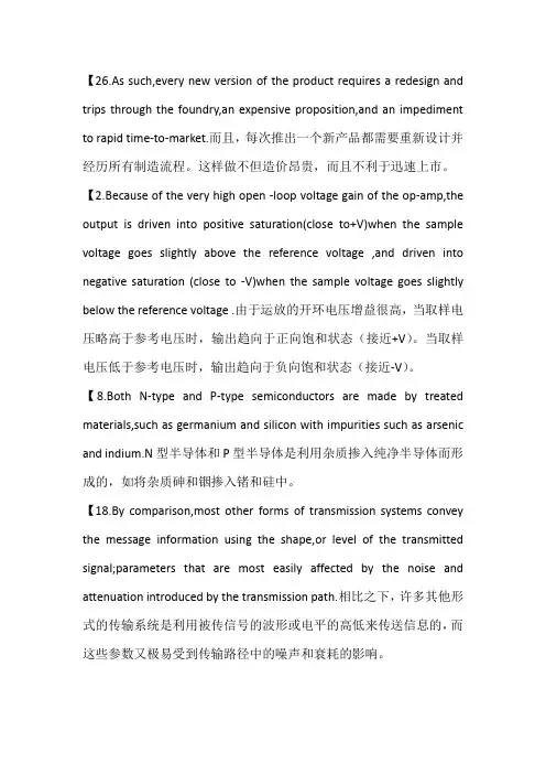
【26.As such,every new version of the product requires a redesign and trips through the foundry,an expensive proposition,and an impediment to rapid time-to-market.而且,每次推出一个新产品都需要重新设计并经历所有制造流程。
这样做不但造价昂贵,而且不利于迅速上市。
【2.Because of the very high open -loop voltage gain of the op-amp,the output is driven into positive saturation(close to+V)when the sample voltage goes slightly above the reference voltage ,and driven into negative saturation (close to -V)when the sample voltage goes slightly below the reference voltage .由于运放的开环电压增益很高,当取样电压略高于参考电压时,输出趋向于正向饱和状态(接近+V)。
当取样电压低于参考电压时,输出趋向于负向饱和状态(接近-V)。
【8.Both N-type and P-type semiconductors are made by treated materials,such as germanium and silicon with impurities such as arsenic and indium.N型半导体和P型半导体是利用杂质掺入纯净半导体而形成的,如将杂质砷和铟掺入锗和硅中。
【18.By comparison,most other forms of transmission systems convey the message information using the shape,or level of the transmitted signal;parameters that are most easily affected by the noise and attenuation introduced by the transmission path.相比之下,许多其他形式的传输系统是利用被传信号的波形或电平的高低来传送信息的,而这些参数又极易受到传输路径中的噪声和衰耗的影响。

电子信息与通信工程专业英语课文翻译2.1————————————————————————————————作者:————————————————————————————————日期:2电路系统与设计2.1电路和系统1.基础概念电荷和导电性在Bohr的原子理论中(以Niels Bohr命名,1885-1962),电子围绕着质子和种子运动。
在相反极性电子和质子的电荷之间的吸引力使得原子连在一起。
具有同种电荷的粒子将会相互排斥。
电荷的测量值是库伦。
一个单独的电子或质子的电荷远小于一库伦,一个电子是—1.6×1(-19)库伦,一个质子是1.6×10(-19)库伦。
自然表明,只有一个质子的电荷和电子是反极性的。
这里没有固有的负极电子,只是很容易被称为正极的和质子负极的。
原子不同形态的电子有不同程度的自由度。
一些材料的形态,例如金属,最外层的电子受到很弱的约束使得它们能够在室温热能量的影响下载原子空间中自由运动。
因为这些事实上不受约束的电子式可以在自身的原子中自由运动的,也可以漂浮在临近的原子周围的空间中,它们常被称为自由电子。
在其他一些形态的材料中如玻璃,它的原子的电子几乎不能自由移动。
当外部的力量如物理摩擦时,能够强迫一些电子离开它们自身的原子,移动到其他物质的原子中,它们在材料的原子中不能很容易的移动。
这些在材料中电子的移动性的关系被认为是电子的导电性。
导电性决定于材料中原子的形态(每个原子核的栀子数,决定他的化学特性。
)和原子是怎样与另一个原子连接在一起的。
有高度灵活电子的材料(许多自由电子)被称为导体,而有很少灵活电子的材料(几乎或是没有自由电子)的材料被称为绝缘体。
必须知道,一些物质的化学特性将在不同环境下改变。
例如,玻璃在室温下是一个非常好的绝缘体,但当把它加热到相当高的温度时它就变成一个导体。
气体如空气,常态下是绝缘体,但如果加热到很高的温度也会变成导体。
大部分金属被加热时导电性能会下降,而被冷制的时候导电性能会更好。
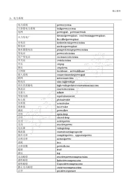
精心整理1、电力系统电力系统powersystem大容量电力系统bulkpowersystem电网powergrid;powernetwork火力发电厂thermalpowerplant;coal-burningpowerplant;fossilfuelpowerplant水电站hydroelectricpowerstation核电站nuclearpowerplant抽水蓄能电站pumpedstoragepowerstation变电站powersubstation用户变电站customersubstation开关站switchstation升压stepup降压stepdown主网架backbone;networkframe接入系统connectiontothepowergrid联网interconnection特高压ultra-highvoltage高压直流输电high-voltagedirect-currenttransmission 换流站converterstation无量大infinite等值电路equivalentcircuit标么值perunitvalue实质值actualvalue基准值basevalue潮流powerflow开环open-loop合环closed-loop有功activepower无功reactivepower电压降voltagedrop载流量currentcarryingcapacity视在功率complexpower;apparentpower自然功率naturalpower消耗loss功率因数powerfactor超前lead滞后lag无功赔偿reactivepowercompenstaion感性赔偿Inductivecompensator容性赔偿Capacitivecompensator静止无功赔偿staticvarcompensation正序positivesequence精心整理负序零序电感电容电抗电阻电纳电导导纳阻抗正弦稳态暂态次暂态绕组抽头有载无载中性点电压比容量比negativesequence zerosequence inductance capacitor reactance resistance susceptance conductance admittance impedance sinusoidalsteadystate transientstate subtransientstate windingtapon-loadoff-loadnetural voltageratio capacityratio过电压负荷中心峰荷基荷居民负荷商业负荷甩负荷过载;过负荷负荷特征负荷曲线负荷率发电输电配电用电用电量停电电力系统稳固功角稳固电压稳固扰动同步不稳固靠谱性收敛overvoltage;surge loadcenter peakload baseload residentialload commercialload loadshedding overload loadcharacteristics loadcurve loadfactor powergeneration powertransmission powerdistribution powerutilization powerconsumption blackout powersystemstability anglestability voltagestability disturbance synchronism instabilityreliabilityconverge精心整理定子转子励磁系统空载惯量三相对称故障单相接地故障短路开路接地临界的均衡感觉电动机振荡谐波电磁感觉充电功率出线进线架空线路电缆建设规模线路输送容量调相调压负荷展望电力系统规划输电规划电磁环网经济电流密度statorrotorexcitationsystemno-loadinertiabalancedthreephasefault singlelinetogroundfaultshort-circuitopen-circuitgroundingcriticalequilibriuminductionmotoroscillationharmonic electromagneticinduction chargingcapacityoutgoinglineincominglineoverheadlinecableconstructionscale transmissioncapacity adjustingthevoltagephaseandmagnitude loadforecasting powersystemplanning transmissionplanning electromagneticloopnetwork economicalcurrentdensity解列disconnection;powersystemseparation 运转方式operatingmode电力电量powerloadandconsumption容载比capacityandloadratio经济比较economiccomparison导线截面选择selectionofconductorcross-section选址选线selectionofsubstationsiteandlinecorridor输变电工程transmissionanddistributionproject电气主接线ElectricalPrimarySystem常用电力专业英语( 1)元件设施三绕组变压器:three-columntransformerThrClnTrans双绕组变压器:double-columntransformerDblClmnTrans电容器: Capacitor并联电容器:shuntcapacitor电抗器: Reactor母线: Busbar输电线: TransmissionLine发电厂: powerplant断路器: Breaker刀闸 ( 隔走开关 ) :Isolator分接头: tap电动机: motor(2)状态参数有功: activepower无功: reactivepower电流: current容量: capacity电压: voltage档位: tapposition有功消耗: reactiveloss无功消耗: activeloss功率因数: power-factor功率: power功角: power-angle电压等级: voltagegrade空载消耗: no-loadloss铁损: ironloss铜损: copperloss空载电流: no-loadcurrent阻抗: impedance正序阻抗: positivesequenceimpedance负序阻抗: negativesequenceimpedance 零序阻抗: zerosequenceimpedance电阻: resistor电抗: reactance电导: conductance电纳: susceptance无功负载: reactiveload或许QLoad有功负载 :activeloadPLoad遥测: YC(telemetering)遥信: YX励磁电流 ( 转子电流 ) : magnetizingcurrent 定子: stator功角: power-angle上限 :upperlimit下限: lowerlimit并列的: apposable高压 :highvoltage低压: lowvoltage中压: middlevoltage单位标准:电能:千瓦时kW.hk,h 小写 W大写有功功率千瓦kWk小写 W大写无功功率千乏kvark,v,a,r均小写视在功率千伏安kVAk 小写 V、 A 大写电压千伏kVk 小写 V 大写长度千米kmk,m 均小写电流安培AA大写电力系统powersystem发电机 generator励磁 excitation励磁器 excitor电压 voltage电流 current母线 bus变压器 transformer升压变压器step-uptransformer高压侧 highside输电系统powertransmissionsystem输电线 transmissionline固定串连电容赔偿fixedseriescapacitorcompensation 稳固 stability电压稳固voltagestability功角稳固anglestability暂态稳固transientstability电厂 powerplant能量输送powertransfer沟通 AC装机容量installedcapacity电网 powersystem落点 droppoint开关站 switchstation双回同杆并架double-circuitlinesonthesametower变电站 transformersubstation赔偿度 degreeofcompensation高抗 highvoltageshuntreactor无功赔偿reactivepowercompensation故障 fault调理 regulation裕度 magin三相故障threephasefault故障切除时间faultclearingtime极限切除时间criticalclearingtime切机 generatortriping高顶值 highlimitedvalue强行励磁reinforcedexcitation线路赔偿器LDC(linedropcompensation)机端 generatorterminal静态 static(state)动向 dynamic(state)单机无量大系统onemachine-infinitybussystem 机端电压控制AVR电抗 reactance电阻 resistance功角 powerangle有功(功率)activepower无功(功率)reactivepower功率因数powerfactor无功电流reactivecurrent降落特征droopcharacteristics斜率 slope额定 rating变比 ratio参照值 referencevalue电压互感器PT分接头 tap降落率 drooprate仿真剖析simulationanalysis传达函数transferfunction框图 blockdiagram受端 receive-side裕度 margin同步 synchronization失掉同步lossofsynchronization阻尼 damping摇晃 swing保护断路器circuitbreaker电阻: resistance电抗: reactance阻抗: impedance电导: conductance电纳: susceptance导纳: admittance电感: inductance电容 :capacitance精心整理热工自动化常用英文缩写词ABCAutomaticboilercontrol锅炉自动控制ACAlternatingcurrent沟通(电)ACCAutomaticcombustioncontrol焚烧自动控制ACPAuxiliarycontrolpanel协助控制盘ACSAutomaticcontrolsystem自动控制系统ACTactuator 履行机构A/DAnalog/digital(conversion)模 / 数(变换)ADPAnnunciationdisplaypanel报警显示板AEHAnalogelectro-模拟式电液调理AFCAirflowcontrol`送风控制AGCAutomaticgenerationcontrol自动发电量控制AIAnaloginput模拟量输入A/MAutomatic/manul 自动/ 手动AOAnalogoutput模拟量输入APCAutomaticplantcontrol电厂自动控制ASSAutomaticsynchronizedsystem自动同期系统ARPAuxiliaryrelaypanel协助继电器盘ATCAutomaticturbinestartuporshutdowncontrolsystem汽轮机自启停系统BCSBurnercontrolsystem焚烧器控制系统BFBoilerfollow锅炉追踪BFCBoilerfuelcontrol锅炉燃料控制BPSBy-passcontrolsystem旁路控制系统BTGBoilerturbinegenerator(panel)锅炉、汽轮机、发电机(控制盘)CCRCentralcontrolroom单元(中央)控制室CHSCoalhandingsystem 输煤控制系统CJCColdjunctioncompensator冷端赔偿器CPUCentralprocessingunit中央办理器CRTCathode-raytube阴极射线管屏幕显示器D/ADigtal/analog(conversion)数 / 模(变换)DASDataacquisitionsystem 计算机监督系统或数据收集系统DCDirectcurrent 直流(电)DCEDatacircuit-terminatingequipment数据电路终端设施DCSDistributedcontrolsystem分别控制系统DDCDirectdigitalcontrol直接数字控制DDPDistributeddatdprocessing分别数据办理DEHDigitalelectro-hydrauliccontrolsystem数字式电液控制系统DIDigitalinput数字量输入DMPDamper挡板、风门DODigitaloutput数字量输出DSBDistributedswitch-board配电盘DTEDataterminalequipment数据中端设施EEPROMElectrically-erasableprogrammablereadonlymrmory电可擦写只读储存器E/PElectro/pneumatic(converter)电/ 气(变换器)EPROMElectricallyprogrammablereadonlymemory 电可编程只读储存器ESExpertsystem 专家系统ETSEmergencytripsystem紧迫停机系统EWSEngineerwokstation工程师工作站FAFullarc全周进汽FBFieldbus现场总线FCBFastcutback (机组)迅速甩负荷FDCFurnacedraftcontrol炉膛压力控制FSSFurnacesafetysystem炉膛安全系统FSSSFurnacesafeguardsupervisorysystem锅炉炉膛安全监控系统GVGovernorvalve调理阀门HBPHigh-pressureby-passvalve高压旁路I&CInstrumentation&control仪表与控制INTInterlock I/OInput/output 连锁输入/输出IDPIntegrateddataprocessing集中数据办理KBKeyboard 键盘LBPLow-pressureby-passvalve低压旁路LCDLiquid-crystaldisplay液晶显示器LEDLightemittingdiode发光二极管LSLimitswitch限位开关LSLevelswitch液位开关M/AManual/automatic 手动/自动MAXMaximum最大值MCCMotorcontrolcenter电动机控制中心MCRMaximumcontinuousrating最大连续运转负荷MCSModulatingcontrolsystem模拟量控制系统MEH(BFTP)micro-electro-hydrauliccontrolsystem(锅炉给水泵汽轮机)电液控制系统MFTMasterfueltrip总燃料跳闸MHCMechanicialhydrauliccontrol机械液压式控制MINMinimum最小值MISManagementinformationsyrtem管理信息系统MTBFMeantimebetweenfailures均匀无故障工作时间MTTFMeantimetofailure无效(故障)前均匀工作时间MTTRMeantimetorepair均匀故障修复时间NCNormallyClosed常闭NONormallyopen 常开OCSOn-offcontrolsystem开关量控制系统OEIOpticelectricinterface光电接口OFTOilfueltrip燃油跳闸OPCOverspeedprotectionCONTROL 超速保护控制OSOperatorstation操作员站PAPartialarc部分进汽PCProgrammablecontroller可编程控制器PCSPulverizercontrolsystem磨煤机控制系统PIPurseinput脉冲量输入PIDProportionalintegralderivative比率 -积分-微分PLCProgrammablelogiccontroller可编程序逻辑控制器POPulseoutput脉冲量输出RAMRandomaccessmemory随机存取储存器RBRunback(辅机故障)迅速甩负荷ROMReadonlymemory只读储存器RTCReheatsteamtemperaturecontrol再热气温控制SBCSootblowercontrolsystem吹灰控制系统SCMSinglechipmicrocomputer单片机SCSSequencecontrolsystem次序控制系统SERSequenceeventsrecorder事件次序记录仪SOESequenceofevents 事件次序记录STSmarttransmitter智能变送器STCSuperheatedsteamtemperaturecontrol过热气温控制TASTurbineautomaticsystem汽轮机自动控制系统TBPTuibineby-passsystem汽轮机旁路系统TCSTurbinecontrolsystem汽轮机控制系统TFTurbinefollow汽轮机追踪TSITurbinesupervisoryinstrument汽轮机监督仪表UCCUnitcoordinatedcontrol机组协调控制ULDUnitloaddemand(command) 机组负荷指令UPSUninterruptedpowersystem不中断电源WTSWatertreatmentcontrdsystem水办理控制系统。
1 Power Electronic ConceptsPower electronics is a rapidly developing technology. Components are tting higher current and voltage ratings, the power losses decrease and the devices become more reliable. The devices are also very easy tocontrol with a mega scale power amplification. The prices are still going down pr. kVA and power converters are becoming attractive as a mean to improve the performance of a wind turbine. This chapter will discuss the standard power converter topologies from the simplest converters for starting up the turbine to advanced power converter topologies, where the whole power is flowing through the converter. Further, different park solutions using power electronics arealso discussed.1.1 Criteria for concept evaluationThe most common topologies are selected and discussed in respect to advantages and drawbacks. Very advanced power converters, where many extra devices are necessary in order to get a proper operation, are omitted.1.2 Power convertersMany different power converters can be used in wind turbine applications. In the case of using an induction generator, the power converter has to convert from a fixed voltage and frequency to a variable voltage and frequency. This may be implemented in many different ways, as it will be seen in the next section. Other generator types can demand other complex protection. However, the most used topology so far is a soft-starter, which is used during start up in order to limit the in-rush current and thereby reduce the disturbances to the grid.1.2.1 Soft starterThe soft starter is a power converter, which has been introduced to fixedspeed wind turbines to reduce the transient current during connection or disconnection of the generator to the grid. When the generator speed exceeds the synchronous speed, the soft-starter is connected. Using firing angle control of the thyristors in the soft starter the generator is smoothly connected to the grid over a predefined number of grid periods. An example of connection diagram for the softstarter with a generator is presented in Figure1.Figure 1. Connection diagram of soft starter with generators.The commutating devices are two thyristors for each phase. These are connected in anti-parallel. The relationship between the firing angle (﹤) and the resulting amplification of the soft starter is non-linear and depends additionally on the power factor of the connected element. In the case of a resistive load, may vary between 0 (full on) and 90 (full off) degrees, in the case of a purely inductive load between 90 (full on) and 180 (full off) degrees. For any power factor between 0 and 90 degrees, w ill be somewhere between the limits sketched in Figure 2.Figure 2. Control characteristic for a fully controlled soft starter.When the generator is completely connected to the grid a contactor (Kbyp) bypass the soft-starter in order to reduce the losses during normal operation. The soft-starter is very cheap and it is a standard converter in many wind turbines.1.2.2 Capacitor bankFor the power factor compensation of the reactive power in the generator, AC capacitor banks are used, as shown in Figure 3. The generators are normally compensated into whole power range. The switching of capacitors is done as a function of the average value of measured reactive power during a certain period.Figure 3. Capacitor bank configuration for power factor compensation ina wind turbine.The capacitor banks are usually mounted in the bottom of the tower or in thenacelle. In order to reduce the current at connection/disconnection of capacitors a coil (L) can be connected in series. The capacitors may be heavy loaded and damaged in the case of over-voltages to the grid and thereby they may increase the maintenance cost.1.2.3 Diode rectifierThe diode rectifier is the most common used topology in power electronic applications. For a three-phase system it consists of six diodes. It is shown in Figure 4.Figure 4. Diode rectifier for three-phase ac/dc conversionThe diode rectifier can only be used in one quadrant, it is simple and it is notpossible to control it. It could be used in some applications with a dc-bus.1.2.4 The back-to-back PWM-VSIThe back-to-back PWM-VSI is a bi-directional power converter consisting of two conventional PWM-VSI. The topology is shown in Figure 5.To achieve full control of the grid current, the DC-link voltage must be boosted to a level higher than the amplitude of the grid line-line voltage. The power flow of the grid side converter is controlled in orderto keep the DC-link voltage constant, while the control of the generator side is set to suit the magnetization demand and the reference speed. The control of the back-to-back PWM-VSI in the wind turbine application is described in several papers (Bogalecka, 1993), (Knowles-Spittle et al., 1998), (Pena et al., 1996), (Yifan & Longya, 1992), (Yifan & Longya, 1995).Figure 5. The back-to-back PWM-VSI converter topology.1.2.4.1 Advantages related to the use of the back-to-back PWM-VSIThe PWM-VSI is the most frequently used three-phase frequency converter. As a consequence of this, the knowledge available in the field is extensive and well established. The literature and the available documentation exceed that for any of the other converters considered in this survey. Furthermore, many manufacturers produce components especially designed for use in this type of converter (e.g., a transistor-pack comprising six bridge coupled transistors and anti paralleled diodes). Due to this, the component costs can be low compared to converters requiring components designed for a niche production.A technical advantage of the PWM-VSI is the capacitor decoupling between the grid inverter and the generator inverter. Besides affording some protection, this decoupling offers separate control of the two inverters, allowing compensation of asymmetry both on the generator side and on the grid side, independently.The inclusion of a boost inductance in the DC-link circuit increases the component count, but a positive effect is that the boost inductance reduces the demands on the performance of the grid side harmonic filter, and offers some protection of the converter against abnormal conditions on the grid.1.2.4.2 Disadvantages of applying the back-to-back PWM-VSIThis section highlights some of the reported disadvantages of the back-to-back PWM-VSI which justify the search for a more suitable alternative converter:In several papers concerning adjustable speed drives, the presence of the DC link capacitor is mentioned as a drawback, since it is heavy and bulky, it increases the costs and maybe of most importance, - it reduces the overall lifetime of the system. (Wen-Song & Ying-Yu, 1998); (Kim & Sul, 1993); (Siyoung Kim et al., 1998).Another important drawback of the back-to-back PWM-VSI is the switching losses. Every commutation in both the grid inverter and the generator inverter between the upper and lower DC-link branch is associated with a hard switching and a natural commutation. Since the back-to-back PWM-VSI consists of two inverters, the switching losses might be even more pronounced. The high switching speed to the grid may also require extra EMI-filters.To prevent high stresses on the generator insulation and to avoid bearing current problems (Salo & Tuusa, 1999), the voltage gradient may have to be limited by applying an output filter.1.2.5 Tandem converterThe tandem converter is quite a new topology and a few papers only have treated it up till now ((Marques & Verdelho, 1998); (Trzynadlowski et al., 1998a); (Trzynadlowski et al., 1998b)). However, the idea behind the converter is similar to those presented in ((Zhang et al., 1998b)), where the PWM-VSI is used as an active harmonic filter to compensate harmonic distortion. The topology of the tandem converter is shown inFigure 6.Figure 6. The tandem converter topology used in an induction generator wind turbine system.The tandem converter consists of a current source converter, CSC, in thefollowing designated the primary converter, and a back-to-back PWM-VSI, designated the secondary converter. Since the tandem converter consists of four controllable inverters, several degrees of freedom exist which enable sinusoidal input and sinusoidal output currents. However, in this context it is believed that the most advantageous control of the inverters is to control the primary converter to operate in square-wave current mode. Here, the switches in the CSC are turned on and off only once per fundamental period of the input- and output current respectively. In square wave current mode, the switches in the primary converter may either be GTO.s, or a series connection of an IGBT and a diode.Unlike the primary converter, the secondary converter has to operateat a high switching frequency, but the switched current is only a small fraction of the total load current. Figure 7 illustrates the current waveform for the primary converter, the secondary converter, is, and the total load current il.In order to achieve full control of the current to/from the back-to-back PWMVSI, the DC-link voltage is boosted to a level above the grid voltage. As mentioned, the control of the tandem converter is treated in only a few papers. However, the independent control of the CSC and the back-to-back PWM-VSI are both well established, (Mutschler & Meinhardt, 1998); (Nikolic & Jeftenic, 1998); (Salo & Tuusa, 1997); (Salo & Tuusa, 1999).Figure 7. Current waveform for the primary converter, ip, the secondary converter, is, and the total load current il.1.2.5.1Advantages in the use of the Tandem ConverterThe investigation of new converter topologies is commonly justifiedby thesearch for higher converter efficiency. Advantages of the tandem converter are the low switching frequency of the primary converter, and the low level of the switched current in the secondary converter. It is stated that the switching losses of a tandem inverter may be reduced by 70%, (Trzynadlowski et al., 1998a) in comparison with those of an equivalent VSI, and even though the conduction losses are higher for the tandem converter, the overall converter efficiency may be increased.Compared to the CSI, the voltage across the terminals of the tandem converter contains no voltage spikes since the DC-link capacitor of the secondary converter is always connected between each pair of input- and output lines (Trzynadlowski et al., 1998b).Concerning the dynamic properties, (Trzynadlowski et al., 1998a) states that the overall performance of the tandem converter is superior to both the CSC and the VSI. This is because current magnitude commands are handled by the voltage source converter, while phase-shift current commands are handled by the current source converter (Zhang et al., 1998b).Besides the main function, which is to compensate the current distortion introduced by the primary converter, the secondary converter may also act like an active resistor, providing damping of the primary inverter in light load conditions (Zhang et al., 1998b).1.2.5.2 Disadvantages of using the Tandem ConverterAn inherent obstacle to applying the tandem converter is the high number of components and sensors required. This increases the costs and complexity of both hardware and software. The complexity is justified by the redundancy of the system (Trzynadlowski et al., 1998a), however the system is only truly redundant if a reduction in power capability and performance is acceptable.Since the voltage across the generator terminals is set by the secondary inverter, the voltage stresses at the converter are high.Therefore the demands on the output filter are comparable to those when applying the back-to-back PWM-VSI.In the system shown in Figure 38, a problem for the tandem converter in comparison with the back-to-back PWM-VSI is the reduced generator voltage. By applying the CSI as the primary converter, only 0.866% of the grid voltage can be utilized. This means that the generator currents (and also the current through the switches) for the tandem converter must be higher in order to achieve the same power.1.2.6 Matrix converterIdeally, the matrix converter should be an all silicon solution with no passive components in the power circuit. The ideal conventional matrix converter topology is shown in Figure 8.Figure 8. The conventional matrix converter topology.The basic idea of the matrix converter is that a desired input current (to/from the supply), a desired output voltage and a desired output frequency may be obtained by properly connecting the output terminals of the converter to the input terminals of the converter. In order to protect the converter, the following two control rules must be complied with: Two (or three) switches in an output leg are never allowed to be on at the same time. All of the three output phases must be connected to an input phase at any instant of time. The actual combination of the switchesdepends on the modulation strategy.1.2.6.1 Advantages of using the Matrix ConverterThis section summarises some of the advantages of using the matrix converter in the control of an induction wind turbine generator. For a low output frequency of the converter the thermal stresses of the semiconductors in a conventional inverter are higher than those in a matrix converter. This arises from the fact that the semiconductors in a matrix converter are equally stressed, at least during every period of the grid voltage, while the period for the conventional inverter equals the output frequency. This reduces thethermal design problems for the matrix converter.Although the matrix converter includes six additional power switches compared to the back-to-back PWM-VSI, the absence of the DC-link capacitor may increase the efficiency and the lifetime for the converter (Schuster, 1998). Depending on the realization of the bi-directional switches, the switching losses of the matrix inverter may be less than those of the PWM-VSI, because the half of the switchings become natural commutations (soft switchings) (Wheeler & Grant, 1993).1.2.6.2 Disadvantages and problems of the matrix converterA disadvantage of the matrix converter is the intrinsic limitation of the output voltage. Without entering the over-modulation range, the maximum output voltage of the matrix converter is 0.866 times the input voltage. To achieve the same output power as the back-to-back PWM-VSI, the output current of the matrix converter has to be 1.15 times higher, giving rise to higher conducting losses in the converter (Wheeler & Grant, 1993).In many of the papers concerning the matrix converter, the unavailability of a true bi-directional switch is mentioned as one of the major obstacles for the propagation of the matrix converter. In the literature, three proposals for realizing a bi-directional switch exists. The diode embedded switch (Neft & Schauder, 1988) which acts like a truebi-directional switch, the common emitter switch and the common collector switch (Beasant et al., 1989).Since real switches do not have infinitesimal switching times (which is not desirable either) the commutation between two input phases constitutes a contradiction between the two basic control rules of the matrix converter. In the literature at least six different commutation strategies are reported, (Beasant et al., 1990); (Burany, 1989); (Jung & Gyu, 1991); (Hey et al., 1995); (Kwon et al., 1998); (Neft & Schauder, 1988). The most simple of the commutation strategies are those reported in (Beasant et al., 1990) and (Neft & Schauder, 1988), but neither of these strategies complies with the basic control rules.译文1 电力电子技术的内容电力电子技术是一门正在快速发展的技术,电力电子元器件有很高的额定电流和额定电压,它的功率减小元件变得更加可靠、耐用.这种元件还可以用来控制比它功率大很多倍的元件。
2024年2月Electric Power Information and Communication Technology Feb. 2024 中图分类号:TP394.1文献标志码:A文章编号:2095-641X(2024)02-034-06DOI:10.16543/j.2095-641x.electric.power.ict.2024.02.05著录格式:李建康,韩帅,陈没,等.基于深度学习的输电通道入侵物体识别方法研究[J].电力信息与通信技术,2024,22(2):34-39.基于深度学习的输电通道入侵物体识别方法研究李建康1,韩帅2,陈没2,廖思卓2,王道累1,赵文彬1(1.上海电力大学能源与机械工程学院,上海市浦东新区201306;2.中国电力科学研究院有限公司,北京市海淀区100192)Research on Intrusion Object Recognition Method of Transmission CorridorBased on Deep LearningLI Jiankang1, HAN Shuai2, CHEN Mo2, LIAO Sizhuo2, WANG Daolei1, ZHAO Wenbin1(1. College of Energy and Mechanical Engineering, Shanghai University of Electric Power, Pudong New Area, Shanghai 201306, China;2. China Electric Power Research Institute, Haidian District, Beijing 100192, China)摘要:针对输电通道在线监测过程中入侵物体大小差异巨大、部分图像对比度低等问题,结合异物图像的特征,提出了一种基于目标检测算法的输电通道入侵物体识别方法。
电子科学与技术专业英语(English for Electronic Science andtechnology)同样,一个离散时间系统-就是一个系统,将离散输入输出-离散描述如图3-1-5(B)。
其中x(n)是输入,y(n)是输出,h(n)是系统单元样本响应。
2009 8 28 6年月日时56分电子信息与通信工程专业英语我们可以通过采样的概念把连续时间和离散时间系统结合在一起,我们可以开发一些关于离散时间系统用于处理连续时间信号的见解。
2009 8 28 6年月日时56分电子信息与通信工程专业英语目前,许多数字信号处理方法已广泛应用于科学技术领域。
因此我们以数字信号系统为例,在下一节中描述了一些系统性能。
2009 8 28 6年月日时56分电子信息与通信工程专业英语3、数字信号系统的一些特性系统的线性度T { AX1(N)+ BX2(n)} = 1可引起肿瘤(n)+ 2(N)系统的时间不变性被定义为t x(n?)N0)} = y(n?N0)线性时不变的是独立的属性。
2009 8 28 6年月日时56分电子信息与通信工程专业英语Communtative:x(n)?y(n)=y(n)?x(n)联想:x(n)y(n)?* w(n)=x(n)*?y(n)*w(n)?????分配:x(n)*?y(n)+w(n)?=?x(n)y(n)x(n)* w(n)?????2009 8 28 6年月日时56分电子信息与通信工程专业英语4。
信号能量与功率在有限总能量下,即信号的最小值为零。
②信号③信号①信号是有限平均功率的。
P∞是不是p或不是的信号。
E∞是有限的。
2009 8 28 6年月日时56分电子信息与通信工程专业英语练习1。
请下列短语译成汉语。
?2。
请下列短语译成英语。
2009 8 28 6年月日时56分电子信息与通信工程专业英语正文3.2数字信号处理1。
简介2。
傅立叶分析3。
FIR数字滤波器设计4。
窗函数2009 8 28 6年月日时56分电子信息与通信工程专业英语术语忠诚,保真度,(收音机,录音设备等的)逼真度,保真度,重现精度?感官的。
32Int. J. Critical Infrastructures, Vol. 4, Nos. 1/2, 2008Copyright © 2008 Inderscience Enterprises Ltd.The security of power systems and the role of information and communication technologies: lessons from the recent blackoutsAlberto Stefanini* and Marcelo MaseraInstitute for the Protection and Security of the Citizen Joint Research Centre of the European Commission Via E. Fermi, 1, 21020 Ispra (VA), Italy E-mail: Alberto.Stefanini@jrc.it E-mail: Marcelo.Masera@jrc.it *Corresponding authorAbstract: This paper analyses the impact of information and communication technologies upon the security of networked infrastructures, making specific reference to the situation of the electric power sector. It discusses the lessons learnt from the recent blackouts, and concludes with the identification of the main technological security challenges faced in this field. In recent years, both Europe and the USA have experienced a significant number of huge blackouts, whose frequency and impact looks to be progressively growing. This paper shows that these events had common roots in the fact that current risk assessment methodologies and current system controls no longer appear to be adequate. Beyond the growing complexity of the electrical system as a whole, two main reasons can be listed: (1) system analysis procedures based on these methodologies did not identify security threats emerging from failures of critical physical components; and (2) online controls were not able to avoid system collapse.Keywords: electric power infrastructure; security; risk assessment; control systems; standards; R&D issues.Reference to this paper should be made as follows: Stefanini, A. and Masera, M. (2008) ‘The security of power systems and the role of information and communication technologies: lessons from the recent blackouts’, Int. J. Critical Infrastructures , Vol. 4, Nos. 1/2, pp.32–45.Biographical notes: Alberto Stefanini graduated in Electronic Engineering at the University of Bologna in 1974. He is currently with the Joint Research Centre of the European Commission, Institute for the Protection and Security of the Citizen, where he is involved in studies on critical infrastructure vulnerabilities, and in the coordination of research activities EU-wide on this subject. Until September 2005, he was with CESI, an electrical engineering and research company based in Milan, where he coordinated research on power system security and diffusion of R&D results. His background includes marketing of engineering and software services in the energy sector, research in artificial intelligence, and design of telecommunications devices and micro systems. He is the author of over 30 scientific and technical publications and one book.Marcelo Masera has been an Electronics and Electrical Engineer since 1980, and an Officer of the European Commission at the Joint Research Centre since November 2000. He is in charge of the Information Security of Critical Networked Infrastructures area within the Institute for the SecurityThe security of power systems and the role of ICTs 33and Protection of the Citizen. His interests are in the dependability andsecurity of complex socio-technical systems, and specifically those relatedto critical infrastructures, large-scale systems-of-systems, information andcommunication technologies and the information society. He has publishedmore than 60 papers in the fields of dependability, security and risk.The content of this paper is the sole responsibility of the authors and in no wayrepresents the view of the European Commission or its services.1 The changing power infrastructure: the E+I paradigmAs discussed in Gheorghe et al. (2006), networked infrastructures, and in particular the power systems, are experiencing fundamental changes in the way they are controlled and monitored. One of the main factors behind this evolution is the pervasive and intensive use of Information and Communication Systems (ICS).The application of electronic technologies to power systems began as soon as those technologies were available, because they appeared as an effective means of implementing control and protection mechanisms. The massive incorporation of digital solutions has changed the character of power systems. In Gheorghe et al. (2006), this industrial phenomenon is denominated the E+I paradigm: this designates the new reality of the power infrastructure characterised by the integration of two elements, namely, ‘Electricity plus Information’.The use of ICS has two sides: on the one side it provides new means of improving the operational and monitoring capabilities, but on the other it opens up dangerous risks of cyber threats. Therefore, the assessment of the risks of the electricity infrastructure cannot ignore the information security aspects of ICS.Taking as an example the evolution of the electricity systems in Europe, it is possible to appreciate how the two main structural changes of the last decade (i.e., unbundling of the generation, transmission and distribution sectors, and use of international interconnections for increasing flows supporting the electricity market) would not have been possible without the parallel application of ICS. Within each country, the application of the regulations over the infrastructure depends on the flow of information between actors: be it the application of connectivity rules or tariffs, electricity and information go together.All aspects of the power infrastructure – from the commercial operations in electricity exchanges, to enhanced services to end users, to the assessment and management of risk and costs, etc. – all aspects of electric power are infused with information. The infrastructure will see the amalgamation of electricity and information. This is the emergence of an E+I scenario. Its reality is central to the understanding of the security risks, and the effective use of ICS. Four phases can be identified in the evolution towards the E+I paradigm (see Figure 1, Gheorghe et al. (2006)):1 During the 1950s and 1960s, power systems worked on their own, evolving fromisolated systems to the first networks. The application of electronics and the firstanalogue computer devices closely followed their availability (e.g., frequency relays and offline tools such as analogue simulators). E was isolated, and the loop with Ipassed through human beings.34 A. Stefanini and M. Masera2 In the 1970s, digital electronics began to replace the functions that were previouslyperformed by electromechanical and analogue equipment, e.g., direct control over some functions. Analogue and digital equipment coexisted for some time. In parallel, computing centres were implemented for data storage and business administrative functions. Power systems evolved networking whole regions. E received directsupport from I, first at the equipment level, then linked to entire installations.3 By the mid-1980s, power systems became wired and computerised, and thepossibility of having remote access to distant facilities pushed the development of communication networks. Power systems were nationally integrated andinternational interconnections were developed. Dispatch centres rapidly developed their capabilities. The diffusion of the internet affected all business processes. Itransformed into an indispensable partner of E.4 From the late 1990s onward, companies and national infrastructures became fullydigitalised. Data flows grew profusely between the industrial and the business sides of companies. Energy markets functioned online. International power networksfurther developed and cross-border flows increased following the requirements of the markets. The vast interconnection among national grids was not just accompanied but also enabled by ICS. Sensors and actuators could be reached through a variety of communication means. On the other hand, the pervasiveness of information allowed new functions across systems. E and I became fused into a single reality: E+I.Figure 1 Evolution towards E+ISource:Derived from Gheorghe et al., 2006The E+I scenario presents security challenges that are not only more numerous or more complex than in the previous periods, but are also different in nature. The E branch of security cannot be analysed or solved without consideration of the I branch. The E and I parts cannot be aggregated, but the compound infrastructure E+I requires a joint security approach.The security of power systems and the role of ICTs 35 2 Networked infrastructure failures: lessons from the summer2003 blackoutsNetwork-shaped, highly distributed infrastructures have to take into consideration a greater diversity of threats than single systems. For instance, in addition to local technical faults, human errors and natural disasters, one has to add systemic failures emerging from the topological and organisational structure of the infrastructure. Moreover, since infrastructural networks are typically geographically distributed, natural forces might affect them owing to the accumulation of dispersed events; and owing to the relevance of infrastructures to national security, deliberate attacks take on a new and important significance.Threats against the electrical system are also growing from the point of view of its adequacy: demand is always growing, and, although this growth may be forecast, it cannot be easily faced anytime, also because the public often withstands construction of new power-generating plants and transmission lines (UCTE, 2004a). Interconnections among national power systems have been developed in the past 50 years so as to ensure mutual assistance between national subsystems, by allowing exchanges between these systems. Today’s market development, with its high level of cross-border exchanges, was out of the scope of the original system design. Transactions are increasing, following electrical system liberalisation, and this involves operating the whole infrastructure closer to security limits (Eurelectric, 2004). As discussed in Gheorghe et al. (2006), this discrepancy between the physical infrastructure and the requirements put to its operation has been described as ‘evolutionary unsuitability’ for emphasising this evolving mismatch.In recent years, both Europe and the USA have experienced a significant number of huge blackouts, whose frequency and impact looks to be progressively growing. Summer 2003 especially was characterised by electricity supply disruption events that had a wide impact on a number of key economies; these events contributed to directing attention to how crucially modern societies depend upon the correct operation of the electric infrastructure. They evidenced the extent to which all technological infrastructures depend on electricity, although most interdependencies are usually not perceived, not only by the public at large, but also by most infrastructure operators. These events had common roots in the emerging vulnerabilities of electrical system controls (intended as the procedures for system management, and the related information and communication infrastructure, comprehensive of monitoring, actuation and protection devices). They also evidenced the inadequacy, in that respect, of current risk assessment methodologies. Most recent incidents arose from a pattern where an initial fault of the electrical infrastructure was not confined because protection systems acted on a purely local basis, and the monitoring equipment failed to alarm human operators in a timely manner:• 14 August 2003 – Eastern North AmericaAccording to the joint US-Canada Task Force (2005), in a way this event wasinduced and, above all, inappropriately managed because of some pending problems affecting the monitoring and control equipment. The state estimator used to preview the likely system evolution was out of order for approximately four hours and was restarted a few minutes before the blackout. Another fault in the SCADA server36 A. Stefanini and M. Maseraput alarm management out of operation and slowed down the entire SCADAfunctionality, to the effect of making control room operators almost totally blindregarding the event.• 28 August 2003 – South London, UKThe cause of this incident was the incorrect rating of a protection relay, undiscovered by the extensive quality control and commissioning procedures. Following an alarm caused by a low oil level in a shunt reactor, a transformer was disconnected from the distribution system, as is the normal practice in this case. Unexpectedly, automatic protection equipment interpreted the change in power flow due to the transformer disconnection as a fault, and disconnected 410 000 customers, including parts of the London Underground and Network Rail (National Grid, 2003).• 23 September 2003 – Southern Sweden and eastern DenmarkThe root cause of this incident was the combination of the initial loss of a largenuclear unit with the double bus-bar fault in the substation on the West coast,which drove the system beyond its security criteria (N-3 situation). Approximately five min after the initial fault (loss of a 1250 MW generation unit), a doublebus-bar fault in a substation on the west coast disconnected four out of five 400 kV transmission lines. Increasing flows on the remaining lines and low voltage insouthern Sweden caused protection relays to trip, and southern Sweden and eastern Denmark were completely disconnected after 90 seconds.• 28 September 2003 – ItalyThe root cause of the event was the trip of the Lukmanier line in Switzerland, due toa tree flashover. In that situation, the Swiss operator had to rely on countermeasuresavailable outside Switzerland, but lacked a sense of urgency regarding the overload of a second line connecting the Swiss system to Italy, and called for inadequatecountermeasures in Italy (UCTE, 2004a). According to the Italian Authority (AEEG, 2003; 2004), the subsequent degradation of the Italian system and its long restoration were mostly due to either inadequate or inappropriate performance of protectionequipment. All three categories of protection systems – critical section control, load relief equipment and load rejection equipment – failed for different reasons. It is also remarkable that 21 out of 52 power plants failed to compensate for the lack ofimported power, because most of them rejected load at about 49 Hz, well above the stated threshold of 47.5 Hz (AEEG, 2003; 2004).3 Open questionsMarket liberalisation and the creation of a single European market have changed the conditions for ensuring a secure electricity supply. The European grid is hosting the transit of commercial flows over long distances, driving system operators to become more and more interdependent, while at the same time substantial commercial interests have appeared and the number of market actors has significantly increased. The major political question raised by recent power outages is whether liberalisation did trigger aThe security of power systems and the role of ICTs 37 process of mismanagement of the electrical infrastructure, whose final outcome is an increase in the frequency and severity of power outages. As pointed out by the authoritative Eurelectric (2004) report ‘Power Outages in 2003’:“major power outages are viewed by consumers as a failure of the wholeelectricity industry, irrespective of the actual reasons and contributing factors(…) The power outage events may increase scepticism to liberalisation incitizens, and have already done so in some officials both at national andEuropean levels.”The main lesson implied by the blackouts is that neither electrical system management, nor its operating procedures, nor system automation was revised so as to adequately cope with the liberalisation scenario. By comparing the two major events discussed in Section 2, the Eastern North America and the Italian blackout, we may recognise a common pattern:• Regarding the Italian case, the UCTE (2004a) report points out that, as an accident originating in Switzerland, it required the timely intervention by the Italian operator to be adequately dealt with. However, the Italian operator did not have directvisibility on the events that happen in other countries, and therefore had to bewarned on the phone by the Swiss operator (!).• Similarly, the US system lacks a governing body that may effectively coordinate operators’ activities. Although NERC (2005a), the North American coordinatingbody, did advance a proposal to that effect, this initially met the opposition of several regional operators.1 Moreover, the malfunction of critical supervisory equipment, which were to act as a common reference for the operators involved in the triggering event, was a crucial factor, in that it deceived operators on the likely progression of events.• In the Italian case, restoration was further compounded by critical infrastructure interdependency. After two hours, the emergency supply to several vital information and communication equipment ceased to work, hence the equipment could no longer operate. This required turning to a backup satellite facility for communication with on-site personnel, who had to manually operate all the remotely controlledequipment, thus making restoration far longer and more cumbersome (AEEG, 2004). • In the US case, restoration was even longer and more cumbersome, owing to the inherent complexity and the extension of the crisis, the plethora of actorsinvolved, and inadequacies of automation and support equipment (US-CanadaTask Force, 2005).The Italian case clearly outlines how the two basic attributes of power service reliability, i.e., adequacy and security, could in some cases be somewhat contrasting. During the summer crisis of 26 June 2003, owing to exceptional weather conditions, the Italian operator was unable to meet demand requirements (failure to provide adequate service), while the September blackout scenario is one where the Italian system, crucially dependent on power imports, failed when this import was suddenly cut off owing to a fault, thus showing a lack of overall security. The system operator was driven to crucially rely on imports for several reasons, among them pressure from public opinion after the summer crisis, thus operating the system closer to its capacity and security limits. Also, the deployment of the Italian crisis is largely due to premature tripping of protection38 A. Stefanini and M. Maserarelays, made to protect specific assets, like power plants, transformers and lines; in this case, security in asset protection prevailed over adequacy, i.e., caused a total failure to meet demand.In conclusion, there is a drive towards integration of the European electricity market, huge opportunities for advanced ICS in this domain and a need to address new vulnerabilities. The main open questions appear to be twofold, as discussed next.3.1 Inadequacy of the current practices to assess power system reliabilityMany incidents arise from a pattern where the initial fault of a power system is compounded by the failure of monitoring equipment and/or incorrect tripping of automatic protection devices (CIGRÉ, 2001). The general industry practice for security assessment has been to use a deterministic approach (CIGRÉ, 2005): the power system is designed and operated to withstand a set of contingencies referred to as ‘normal contingencies’, selected on the basis that they have a significant likelihood of occurrence. This is usually referred to as the N-1 criterion because it examines the behaviour of an N-component grid following the loss of any one of its major components (UCTE, 2004b). Techniques such as load flow analysis are then applied to evaluate the resulting grid conditions. There is no holistic methodology, however, for evaluating risks arising from the power system failures and the automation system together, so as to join physical power system risk assessment with testing/compliance control procedures for automation and protection equipment.3.2 Vulnerabilities of power systems controlsMarket liberalisation involves multiple operators exchanging critical information so as to jointly operate the system; hence a number of key control systems need drastic reviews in order to be fit for operation in a market context. The electrical system depends substantially and increasingly upon its supporting information and communication infrastructure, because almost all vital system functions are remotely controlled, so that an increased control systems complexity, required for secure system operation, may in turn raise system vulnerability, owing to both accidental faults and malicious attacks. Critical infrastructures, and primarily the electrical system, are well-known to be a privileged target in warfare, as well as of terrorist attacks. Unless appropriate measures are taken, this risk will increase with the adoption of open and public information and communication infrastructures for automation support.4 Non-holistic approach to power system reliability assessmentAs discussed in the previous section, many incidents arise from a pattern where the initial fault of a power system is compounded by the failure of monitoring equipment and/or incorrect tripping of automatic protection devices. However, there is no way to join the assessment of risks arising from physical system failures with those arising from failures or attacks to system controls. On the contrary, even the conceptual framework concerning systems security and reliability of power system engineering appears to be quite different from the control systems one.The security of power systems and the role of ICTs 39 Computer systems security was defined by Laprie (1992) as “dependability with respect to the prevention of unauthorised access and/or handling of information”. Computer science views dependability as a global concept, encompassing such properties as availability, reliability, safety, confidentiality, integrity and maintainability. The widespread use of information and communication technologies made the above terminology to be accepted in many sectors of industry, starting from the safety-critical ones – automotive, aerospace, railways, ships, etc., – so that it may be considered a global concept nowadays in control system engineering.Unfortunately, this conceptual framework was not accepted in the power sector, where a different perspective emerged long before the introduction of computer systems to practical applications. Reliability is basically defined in terms of continuity of correct service in power systems engineering, while dependability has no formal meaning, although some authors take it as a synonym of reliability. Power system security is defined as “the ability to withstand sudden disturbances such as electric short circuits or non-anticipated loss of system components” IEEE/CIGRÉ (2004).The practical consequence of these different conceptions is that there exists no holistic approach to risk assessment in power systems, able to evaluate the impact of control system failures together with the impact of physical failures. “Devices used to protect individual equipment may respond to variations in system variables and cause tripping of the equipment, thereby weakening the system and possibly leading to system instability” IEEE/CIGRÉ (2004), thus making automated protection equipment a key vulnerability factor in power systems. However, risk assessment methods in power systems disregard control systems failures: the N-1 criterion takes into account only failures of major electrical components.5 Revision of electrical system controls may increase their vulnerabilities An electric system comprising interconnected power grids (regional, national and supernational) needs complex controls, intended as the procedures for system management, and the related information and communication infrastructure, comprising monitoring, actuation and protection devices, to ensure that the delivery of electrical power anywhere in the system meets certain specified criteria (IEC, 2003). As discussed in the Introduction, such infrastructure has grown together with the electrical system since the 1950s, and in most respects it did not go through a thorough revision after liberalisation to cope with the new security challenges. In summary, these controls appear to be no longer adequate because:• Alarms are not displayed on the screen of the operators who would have to manage them, owing to inappropriate procedures and jurisdictional issues (e.g., alongfrontiers, as in the Switzerland/Italy case, (CRE AEEG, 2004)).• Critical apparatuses are not duplicated so as to remove the effects of their malfunction (North America).• The defence plans of both the North American and the European systems failed.Automatic protection devices were not able to avoid system collapse.40 A. Stefanini and M. Masera• In the Italian case, restoration was made long and cumbersome by inadequacies of the supporting information and communication infrastructure, as far as emergency supply systems are concerned.As a result, there is now a growing consensus about the inadequacy of the European system controls:“The lack or inadequacy of communication, coordination and/or data exchangebetween system operators seems to have played a major role in the escalationof some of the examined events. (…) Binding rules for coordination amongsystem operators both in normal operation and in other situations are desirable.These rules must take account of the new challenges imposed by theliberalisation and integration of the European markets. (...) Tools and means tointensify collection and availability of real-time data should be examined andestablished.” (Eurelectric, 2004)In the aftermath of the 2003 events, the former UC(P)TE non-binding recommendations were transformed into the standards and requirements of the UCTE Operation Handbook and were made binding to all UCTE members via an inter-TSOs Multilateral Agreement signed on 1 July 2005 (UCTE, 2005b). The North American operational procedures alike are being revised by NERC (2005b). In summary, blackouts have triggered a rather hastened overhauling of the whole control system, which may in turn bring about new vulnerabilities. Power systems are multi-jurisdictional infrastructures; hence the real challenge is how to design and implement such a substantial amendment, which involves most of the various private and state entities that participate in some way or another in the operation of the electrical system. In most of the affected countries, particularly the USA and Italy, such process is already in progress so as to reflect changes in the regulatory agreements between TSOs.Meanwhile, new control technologies (Anderson and LeReverend, 1996) are emerging (adaptive protection systems (Jonsson, 2003; Wilks, 2002; Zima,2002), dynamic security assessment (Kundur et al., 2000; Kamwa et al., 2003), wide area measurement systems (Kamwa and Grondin, 2003)). All these systems are inherently based on collecting data in different places, and possibly over an extended period of time, so as to detect an impending malfunction affecting a large portion of the overall system; hence, they are inherently based on fast processing and communication techniques (Naduvathuparambil et al., 2002). Although most of these technologies started to be introduced in the mid-1980s, they are not yet fully mature:• Several issues specifically concerning technology performance are to be addressed, like the criteria for PMU positioning, the reliability of their synchronisation process, the performances of the algorithms (Kamwa and Grondin, 2003).• The potential of innovative technologies for smart local control at the substation level, like adaptive relaying (Phadke and Horowitz, 1990), need to be fully exploited.Their appropriate integration into a multi-level/multi-area hierarchical controlstructure must be investigated.According to a recent workshop among experts of the sector (Stefanini and Servida, 2005), the main challenges implied by the current review of the control systems can be summarised as follows:。