Improving fine-grained irregular shared-memory benchmarks by data reordering
- 格式:pdf
- 大小:188.89 KB
- 文档页数:13
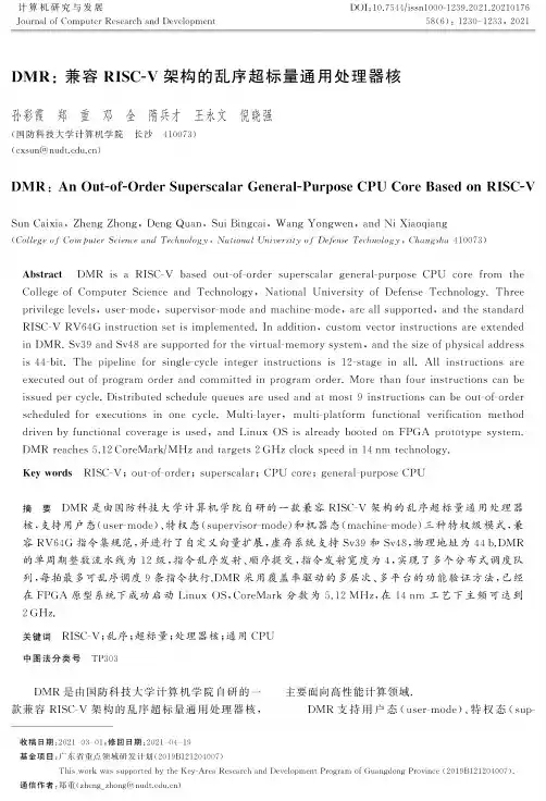
DOI : 10.7544/issnl000-1239.2021.2021017658(6) : 1230 1233, 2021计算机研究与发展Journal of Computer Research and DevelopmentDMR :兼容RISC-V 架构的乱序超标量通用处理器核孙彩霞郑重邓全隋兵才王永文倪晓强(国防科技大学计算机学院 长沙410073)(cxsun@ nudt. edu. cn)DMR : An Out-of-Order Superscalar General-Purpose CPU Core Based on RISC-VSun Caixia, Zheng Zhong, Deng Quan, Sui Bingcai, Wang Yongwen, and Ni Xiaoqiang{College of Computer Science and Technology , National University of Defense Technology , Changsha 410073)Abstract DMR is a RISC-V based out-of-order superscalar general-purpose CPU core from theCollege of Computer Science and Technology, National University of Defense Technology. Three privilege levels , user-mode, supervisor-mode and machine-mode , are all supported, and the standardRISC-V RV64G instruction set is implemented. In addition, custom vector instructions are extended in DMR. Sv39 and Sv48 are supported for the virtual-memory system , and the size of physical addressis 44-bit. The pipeline for single-cycle integer instructions is 12-stage in all. All instructions are executed out of program order and committed in program order. More than four instructions can be issued per cycle. Distributed schedule queues are used and at most 9 instructions can be out-of-orderscheduled for executions in one cycle. Multi-layer, multi-platform functional verification method driven by functional coverage is used, and Linux OS is already booted on FPGA prototype system. DMR reaches 5.12 CoreMark/MHz and targets 2 GHz clock speed in 14 nm technology.Key words RISC-V ; out-of-order ; superscalar ; CPU core ; general-purpose CPU摘 要 DMR 是由国防科技大学计算机学院自研的一款兼容RISC-V 架构的乱序超标量通用处理器核,支持用户态(user-mode)、特权态(supervisor-mode)和机器态(machine -mode)三种特权级模式,兼容RV64G 指令集规范,并进行了自定义向量扩展,虚存系统支持Sv39和Sv48,物理地址为44b.DMR 的单周期整数流水线为12级,指令乱序发射、顺序提交,指令发射宽度为4,实现了多个分布式调度队列,每拍最多可乱序调度9条指令执行.DMR 采用覆盖率驱动的多层次、多平台的功能验证方法,已经 在FPGA 原型系统下成功启动Linux OS^CoreMark 分数为5.12 MHz,在14 nm 工艺下主频可达到2GHz.关键词 RISC-V ;乱序;超标量;处理器核;通用CPU中图法分类号TP303DMR 是由国防科技大学计算机学院自研的一 主要面向高性能计算领域.款兼容RISC-V 架构的乱序超标量通用处理器核,DMR 支持用户态(user-mode).特权态(sup-收稿日期=2021-03-01;修回日期:2021—04—19基金项目:广东省重点领域研发计划(2019B121204007)This work was supported by the Key-Area Research and Development Program of Guangdong Province (2019Bl 21204007).通信作者:关郑重(********************.cn )孙彩霞等:DMR:兼容RISC-V架构的乱序超标量通用处理器核1231ervisor-mode)和机器态(nachin—mode)三种特权级模式,兼容RV64G指令集规范⑴,并进行了自定义向量扩展,虚存系统支持Sv39和Sv48[],物理地址为44b.1微架构DMR的微架构如图1所示.取指宽度为256b,即8条32b指令;译码宽度、寄存器重命名宽度和指令分派宽度都是4;寄存器重命名采用统一的物理寄存器文件方式,如果没有足够的空闲物理寄存器,重命名过程将会发生阻塞;分派后的指令根据指令类型进入相应的指令调度队列,同时也会进入重定序缓冲(reorder buffer,ROB);采用分布式调度队列,根据指令类型设置了整数调度队列、访存调度队列和浮点调度队列;调度队列中的指令就绪后,就会被乱序调度执行,每拍最多可以调度9条指令,其中3条整数指令、1条分支指令、2条load指令、1条store 指令和2条浮点指令;指令被调度执行时读取寄存器文件获取源操作数,源操作数也可能来自旁路的数据;指令提交按序进行;指令Cache和数据Cache 均为64KB,路组相联,Cache行大小均为64B.Fig.1DMR microarchitecture 图1DMR的微体系结构2流水线DMR的流水线如图2所示.单周期整数流水线共有12级,取指4拍,然后是2拍的译码.第1拍进行预译码并处理指令拆分和指令融合,第2拍译码出指令中的操作数信息,以供寄存器重命名时使用;REN为重命名站,DS为指令分派站,根据指令类型,将指令顺序分派到相应的指令调度队列;ISS为指令发射站,发射后进入RF站,读取寄存器文件,读出数据和旁路数据进行选择后送到执行站EX,执行结果在WB站被写回到寄存器文件•Fig.2DMR pipeline 图2DMR的流水线数据Cache命中时的Load-to-use延时是4拍;为了实现较高主频,浮点流水线在读寄存器文件之后增加了一拍MUX用于数据选择.3分支预测DMR采用TAGE(tagged geometric history length)[⑷算法预测分支方向,所实现的TAGE结构包含5个组件(component),即除了基本预测器组件外,还包含4个具有标记的用不同历史长度生成索引的预测组件;2K项的BTB(branch target buffer)、48项的RSB(return stack buffer)和512项的IPB (indirect prediction buffer)分别被用于预测不同类型的分支的目标地址.1232计算机研究与发展2021,58(6)4指令拆分和指令融合DMR在译码阶段将整数和浮点之间的转换指令拆分成2个内部操作,转换操作在浮点单元完成,而读取整数寄存器文件或写入整数寄存器文件的操作在访存部件完成,使得浮点执行单元不需要读写整数寄存器文件,从而可以减少整数寄存器文件的读写端口数目、简化整数数据旁路网络的设计,同时也有利于物理实现•DMR在指令译码阶段将某些指令组合融合成一条指令,然后进行重命名、发射和执行,从而提高指令实际发射宽度,并且可以减少指令占用的乱序执行资源数目和降低调度开销囚.根据RISC-V架构手册的描述⑴,结合DMR 微架构的特点,DMR实现了指令组合的融合,如表1所示.auipc指令和load指令融合,可以实现PC (program counter)相对的32b偏移寻址的数据加载,auipc指令和air指令融合,可以实现PC相对的32b偏移的分支跳转•表1DMR中的指令融合组合Table1Instruction Fusion in DMR组合指令融合组合1auipc rd,imm20;addi rd,rd,imml2组合2auipc rd,imm20;l{b|h|w|d}rd,imml2(rd)组合3auipc rd,imm20;jalr rd,imml2(rd)组合4lui rd,imm20;addi rd,rd,imm12组合5lui rd,imm20;l{b|h|w|d}rd,imm12(rd)组合6lui rd,imm20;jalr rd,imm12(rd)前瞻映射表即可•而分支误预测一旦发生,需要立即清除后续前瞻执行的指令,这时前瞻映射表一般通过重建的方式进行恢复,重建完成前不能进行寄存器的重命名,从而可能造成流水线停顿.DMR在分支指令进行重命名时,会对当前的前瞻映射表进行备份,分支误预测发生时使用该分支对应的备份数据对前瞻映射表进行快速恢复,避免重命名映射表重建导致的流水线停顿.6自定义向量扩展DMR面向高性能计算进行了浮点向量的自定义扩展,该扩展中浮点向量和浮点标量共用一套体系结构寄存器,标量占用寄存器的低位部分•如图3所示,其中D表示双精度浮点,S表示单精度浮点•31o255D63__,S,S,S,S,S,S.s.S .D.D.D.DFig.3Vector formats图3向量格式除了基本的单、双精度浮点计算操作和访存操作外,自定义扩展指令集还支持单、双精度浮点向量乘加操作以及gather load/scatter store操作.向量长度支持动态配置为128b或256b.DMR 的浮点执行单元实现了2条256b流水线,双精度浮点峰值运算性能可达到每个时钟周期16个操作. 7功能验证和性能结果5处理器状态的恢复当发生异常或分支误预测、需要清除前瞻执行的指令时,被清除指令对处理器有关状态的影响同样需要被清除,以恢复到前瞻指令未执行之前的状态•前瞻寄存器重命名映射表就是需要被恢复的处理器状态之一.DMR维护了2个寄存器重命名映射表:前瞻映射表和体系结构映射表.指令重命名时更新前瞻映射表,指令提交时更新体系结构映射表.DMR在指令提交时才报告该指令触发的异常,所以发生异常时,异常指令之前的所有指令都已经完成对体系结构映射表的修改,直接使用体系结构映射表恢复DMR采用覆盖率驱动的多层次、多平台功能验证方法,如图4所示.验证分为3个层次:单元级、核级和系统级.在单元级,针对不同的功能单元搭建了基于UVM (universal verfication methodology)的软模拟平台和形式化验证平台,在核级,搭建了基于trace实时对比的软模拟平台,在系统级搭建了硬件仿真平台.对单元级的软模拟平台和形式化验证平台收集的覆盖率以及核级软模拟平台收集的覆盖率进行合并,统一管理.DMR已经在FPGA原型系统下成功启动Linux OS^CoreMark分数为5.12MHz,在14nm工艺下主频可达到2GHz.孙彩霞等:DMR :兼容RISC-V 架构的乱序超标量通用处理器核1233硬件仿真平台系统级UBOOT, OS应用测试用例验证计划核级Trace 实时对比的 软模拟(随机激励(RISC-V-DV/In-house)](RISC-V 兼容性测试包]覆盖率 收集(手写定向激励]V丿验 证 管 理基于UVM 的软模拟形式化验证单元级□ C □ C覆盖率收集覆盖率收集参 考 文 献[1] RISC-V International. The RISC-V Instruction Set ManualVolume I, Unprivileged ISA, v20191214 [OL]. [2021-0205]. [2]RISC-V International .The RISC-V Instruction Set ManualVolume II : Privileged Architecture, v1.12 [OL]. [2021-0205]. [] Seznec A. A new case for the TAGE branch predictor [C] //Proc of the 44th Annual IEEE/ACM Int Symp on Micro architecture. Piscataway, NJ : IEEE, 2011: 117 227[4] The Journal of Instruction-Level Parallelism. TAGE-SC-L Branch Predictor [OL]. [2020-01-05]. / cbp2014[5] AnandTech. Intel Core versus AMD' K8 architecture [OL].[2021-02-27]. http : //www.anandtech . comSun Caixia , born in 1979. PhD, associate professor . Her main research interests include processor architecture and micro processor design .孙彩霞,1979年生.博士,副研究员.主要研究方向为处理器体系结构和微处理器设计.Zheng Zhong , born in 1986. PhD, assistant professor His main research interestsincludeprocessor microarchitectureandhighperformancecomputing郑 重,1986年生.博士,助理研究员.主要研 究方向为处理器微体系结构和高性能计算.Fig. 4 Functional verification图4功能验证方法2Deng Quan , born in 1989. PhD, assistantprofessor His mainresearchinterestsinclude processing in memory and non-volatilememory .邓 全,1989年生.博士,助理研究员.主要研 究方向为存内计算和非易失性存储器.Sui Bingcai , born in 1981. PhD, associateprofessor His mainresearchinterestsincludemicro-processor architecture , design and optimization .隋兵才,1981年生.博士,副研究员.主要研究方向为微处理器体系结构及其设计与优化.Wang Yongwen , born in 1977. PhD,professor Senior member of CCF His mainresearch interests include processor microarc hitecture and high performance computing.王永文,1977年生.博士,研究员,CCF 高级会员.主要研究方向为处理器微体系结构和高性能计算Ni Xiaoqiang , born in 1974. PhD, associate professor MemberofCCF His mainresearchinterestsincludeprocessorarchitecture ,design andverification倪晓强,1974年生.博士,副研究员,CCF 会 员.主要研究方向为处理器体系结构及其设计与验证.。

0引言随着人工智能的快速发展,卷积神经网络越来越受到人们的关注。
由于它的高适应性和出色的识别能力,它已被广泛应用于分类和识别、目标检测、目标跟踪等领域[1]。
与传统算法相比,CNN 的计算复杂度要高得多,并且通用CPU 不再能够满足计算需求。
目前,主要解决方案是使用GPU 进行CNN 计算。
尽管GPU 在并行计算中具有自然优势,但在成本和功耗方面存在很大的缺点。
卷积神经网络推理过程的实现占用空间大,计算能耗大[2],无法满足终端系统的CNN 计算要求。
FPGA 具有强大的并行处理功能,灵活的可配置功能以及超低功耗,使其成为CNN 实现平台的理想选择。
FPGA 的可重配置特性适合于变化的神经网络网络结构。
因此,许多研究人员已经研究了使用FPGA 实现CNN 加速的方法[3]。
本文参考了Google 提出的轻量级网络MobileNet 结构[4],并通过并行处理和流水线结构在FPGA 上设计了高速CNN 系统,并将其与CPU 和GPU 的实现进行了比较。
1卷积神经网络加速器的设计研究1.1卷积神经网络的介绍在深度学习领域中,卷积神经网络占有着非常重要的地位,它的图像识别准确率接近甚至高于人类的识别水平。
卷积神经网络是同时具有层次结构性和局部连通性的人工神经网络[5]。
卷积神经网络的结构都是类似的,它们采用前向网络模型结构,节点使用神经元来实现分层连接。
并且,相邻层之间的节点是在局部区域内相连接,同一层中的一些神经元节点之间是共享连接权基于FPGA 的卷积神经网络并行加速器设计王婷,陈斌岳,张福海(南开大学电子信息与光学工程学院,天津300350)摘要:近年来,卷积神经网络在许多领域中发挥着越来越重要的作用,然而功耗和速度是限制其应用的主要因素。
为了克服其限制因素,设计一种基于FPGA 平台的卷积神经网络并行加速器,以Ultra96-V2为实验开发平台,而且卷积神经网络计算IP 核的设计实现采用了高级设计综合工具,使用Vivado 开发工具完成了基于FPGA 的卷积神经网络加速器系统设计实现。


mixed_precision的作用mixed_precision是一种用于加速深度学习训练的技术,通过使用低精度的数据类型来代替传统的单精度浮点数,可以在保持模型精度的同时提高训练速度和节省内存空间。
本文将从mixed_precision的原理、优势和应用场景等方面进行探讨。
mixed_precision的核心思想是将计算中所使用的浮点数数据类型从单精度浮点数(float32)降低到半精度浮点数(float16)或者混合精度(mixed precision)。
这是因为深度学习模型中大量的计算都是浮点数运算,而较低的精度可以减少计算量和内存占用。
同时,由于模型参数和梯度的传播过程中也会涉及到浮点数运算,因此将这些数据类型也转换为半精度浮点数可以进一步提高计算效率。
使用mixed_precision可以带来多方面的优势。
首先,降低精度可以减少计算量,从而加速模型的训练过程。
这对于大规模的深度学习模型尤为重要,因为这些模型通常具有巨大的参数量和复杂的计算图。
其次,低精度的数据类型可以节省内存空间,使得可以加载更大的模型或者使用更大的批量大小进行训练。
此外,由于深度学习模型通常具有一定的冗余性,降低精度对于保持模型的精度影响较小。
因此,使用mixed_precision可以在不过多牺牲模型性能的前提下提高训练效率。
mixed_precision的应用场景主要包括两个方面。
首先,在拥有大规模数据集和复杂模型的情况下,mixed_precision可以显著提高训练速度和内存利用率。
例如,在图像分类、目标检测和语音识别等领域,深度学习模型通常需要处理大量的数据和复杂的计算图,使用mixed_precision可以加速训练过程。
其次,在边缘设备和移动设备上,由于计算和存储资源有限,使用mixed_precision可以更好地适应硬件资源的限制,并且提供更高效的推理和部署效果。
为了实现mixed_precision训练,深度学习框架提供了相应的工具和库。

Improving Fine-Grained IrregularShared-Memory Benchmarks by Data ReorderingY.Charlie Hu,Alan Cox and Willy ZwaenepoelDepartment of Computer ScienceRice UniversityHouston,Texas77005ychu,alc,willy@AbstractWe demonstrate that data reordering can substantiallyimprove the performance offine-grained irregular shared-memory benchmarks,on both hardware and softwareshared-memory systems.In particular,we evaluate two dis-tinct data reordering techniques that seek to co-locate inmemory objects that are in close proximity in the physicalsystem modeled by the computation.The effects of thesetechniques are increased spatial locality and reduced falsesharing.We evaluate the effectiveness of the data reordering tech-niques on a set offive irregular applications from SPLASH-2and Chaos.We implement both techniques in a smalllibrary,allowing us to enable them in an application byadding less than10lines of code.Our results on one hard-ware and two software shared-memory systems show that,with data reordering during initialization,the performanceof these applications is improved by12%–99%on the Ori-gin2000,30%–366%on TreadMarks,and14%–269%onHLRC.1.IntroductionOver the last few years we have seen the development ofseveral benchmark suites for shared-memory parallel sys-tems[25,26,30,33].These benchmark suites have provento be invaluable research tools,providing a basis for com-parison between various shared-memory architectures(e.g.,[13,25]).Results from these benchmark suites have,how-ever,also been taken as a measure of the performance thatcan be obtained on shared-memory architectures for theclasses of applications that these benchmark programs rep-resent.parallel systems.The new benchmarks and data reordering library will be made available,and should prove more accu-rate in predicting the performance of shared-memory archi-tectures forfine-grained irregular applications.The paper also makes contributions in the area of optimization tech-niques for shared-memory parallel programming,showing that data reordering techniques can be applied with sub-stantial benefit tofine-grained irregular shared memory pro-grams,and presenting guidelines for the choice of the ap-propriate reordering technique.The rest of this paper is organized as follows.Section2 describes the class offine-grained irregular applications that we are concerned with in this paper and the problems oc-curring with the standard benchmark programs on shared-memory architectures.Section3describes the data reorder-ing techniques that we use.Section4describes the exper-imental environment.We present the results of our exper-iments in Section5.We discuss related work in Section6 and conclude in Section7.2.Fine-grained Irregular ApplicationsThe applications considered in this paper solve some computational problemsq in some given physical domains. The laws of physics cause these applications to have good locality in physical space:the objects interact mostly with other objects close to them in physical space.For instance, the gravitational force quickly decays with the distance,and approximations using only short-range interactions produce accurate results.Such applications are typically parallelized in one of two ways.Thefirst approach,which we refer to as Category1,tries to partition the computation between the processors in an intelligent way,in particular,in such a way that physically close objects are handled by the same processor.This ap-proach reduces the number of interactions between the pro-cessors,but requires a separate data structure to maintain the physical proximity relationships,in addition to the ob-ject array that records the relevant characteristics of each object.This additional data structure typically consists of a collection of cells,each one corresponding to a physically contiguous region,and maintained either in a tree or in a grid.A tree is used in Barnes-Hut and FMM;a grid is used in Water-Spatial.The second approach does not make an attempt at so-phisticated computation partitioning.Instead,it typically uses a simple block partitioning of the object array.The object array entry for a specific object maintains a list of objects in physical proximity,with which interactions are computed.This computational structure occurs in the moldyn and the unstructured benchmarks from the Chaos benchmark set.For both categories of programs,data reordering,i.e.,re-ordering the locations in memory of the objects in the ob-ject array,achieves substantial benefits.Although for both categories the benefits arise from better memory locality, more detailed inspection reveals that the nature of this im-provement in spatial locality is different for both categories. Therefore,different reordering methods achieve the best re-sults for each category.2.1.Category1:Sophisticated Computation Parti-tionThefirst category covers hierarchical N-body algorithms such as the Barnes-Hut method and the Fast Multipole Method[16]and grid-based applications such as Water-Spatial.In these applications,the computation is partitioned using an additional data structure,such as the tree in hierar-chical N-body algorithms or the grid in grid-based N-body algorithms,as opposed to directly partitioned on the object array.The computation is partitioned to have each processor work on some subtrees or subgrids corresponding to some physically contiguous domain.Since objects interact with physically close objects,each processor updates particles or mesh points located within and near the boundary of that physically contiguous domain.The objects are,however, often initialized and stored in the shared address space in some random order,and physically adjacent particles are scattered all through memory.The combination of random placement in memory and computation partitioning grouping physically adjacent bod-ies has two harmful effects.First,the bodies updated by a particular processor are spread throughout memory,giving rise to serious false sharing,especially in page-based soft-ware shared memory systems.False sharing occurs when two or more processors access different locations in the same consistency unit,and at least one of these accesses is a write.It is particularly serious in page-based software shared memory systems,because the consistency unit,a page,contains many bodies,but it is also present on hard-ware shared memory systems where a cache line may con-tain multiple bodies.Second,in order to update its own ob-jects,a processor needs to read its(physically)neighboring objects.These neighboring objects are spread over many different consistency units,which gives rise to a large num-ber of access misses.This effect is more pronounced on systems with a small consistency unit.We use the Barnes-Hut benchmark to illustrate the prob-lem on a4-processor software shared memory system. Barnes-Hut[29]is an-body simulation code using the hi-erarchical Barnes-Hut method[2].A shared tree data struc-ture is used to represent the recursively decomposed sub-domains(cells)of the three-dimensional physical domain containing all the particles.The other shared data structure is an array of particles corresponding to the leaves of theP0P1P2P3Page 0Page 1Page 2Page 3ParticlesFigure 1:Locations of the 168particles in each of the four 4-kilobyte pages to be updated by the four processors.We assume particles do not cross page boundary,and a page contains 4296-byte particles.tree.Each iteration is divided into two steps with barrier synchronization after each.1.Build tree:a single processor reads all of the particles and rebuilds the tree.12.Force evaluation:the processors first divide up the par-ticles in parallel through an in-order traversal of the tree.Specifically,the th processor assigns itself the th subset of contiguous subtrees weighted according to the workload recorded from the previous iteration.The force evaluation for each of the particles then in-volves some partial traversal of the tree.In this step each processor reads a large portion of the tree.The input particles are often generated and stored in the shared particle array in random order,unrelated to their physical location.The Barnes-Hut method is typically used in astrophysics to simulate the evolution of galaxies.Therefore,we fo-cus on the three-dimensional two-Plummer distribution test case of the benchmark here.A single Plummer particle dis-tribution is used to model a single galaxy of stars where the density of stars grows exponentially in moving towards the center of the galaxy.This example consists of 168stars,each represented by a 96-byte record in the object array,oc-cupying in total 44Kbyte pages.The actual generation of the coordinates of the particles uses a random number gen-erator.Figure 1shows the locations in memory to be up-dated by each processor during the second iteration:each processor needs to update locations in several pages.In another example,we ran the code with 32768bod-ies which collectively occupy 3848Kbyte virtual memory pages.We then plot the number of processors sharing each of the 384pages when running on 2,4,8,and 16proces-sors,respectively.The plot,shown in Figure 2,shows that each page is falsely shared by more than half of processors!constructs a sorting key for every object(a particle,a mesh point,etc.)and sorts the keys to generate the rank;second, the actual objects are reordered according to the rank.Since the second step is the same for all reordering methods,wefocus on different ways of generating sorting keys.Figure3 shows the two types of ordering:space-filling curves(Mor-ton or Hilbert)and row or column ordering.3.1Space-Filling CurvesMorton[27]or Hilbert[17]space-filling curves create a linear ordering of points in a higher-dimensional space that preserves the physical adjacency of the points.The Mor-ton ordering is achieved by constructing keys for sorting the subdomains by interleaving the bits of the subdomain coordinates.For Hilbert curves,algorithms based on bit manipulation[5]andfinite-state diagrams[3]exist.An ele-gant recursive algorithm can be found in[18].We focus on Hilbert reordering because it traverses only contiguous sub-domains and thus potentially results in better data locality in the reordered data structure.3.2Column and Row OrderingThe sorting keys for row or column ordering are gen-erated by simply concatenating the bits of the z–,y–, and x–coordinates of data units.For column ordering,z-coordinates form the least significant bits,and for row or-dering,x-coordinates form the least significant bits.3.3Category1ApplicationsTo combat poor spatial locality resulting from the mis-match between the random data ordering of the main data structure and the physical locality desired by the computa-tion partition,we reorder the main data structure once using some space-filling curve.Going back to the example from Section2,the locations of the particles to be updated by each processor after Hilbert reordering are shown in paring Figure4with Figure1,one can see that most particles in the same pages will be updated by the same processors.The effectiveness of this data reordering on re-ducing false sharing can be dramatic.For example,if we reorder the particle array in the Barnes-Hut benchmark de-scribed in Section2.1using the Hilbert ordering,the degree of false sharing on the same384pages containing the32768 particles is drastically reduced,as shown in Figure5.On16 processors,the average number of processors sharing a page is reduced from9.5to3.3.4Category2ApplicationsFor irregular applications in Category2,reordering the main data structure using space-filling curves does not al-P0P1P2P3Page 0Page 1Page 2Page 3ParticlesFigure4:Locations of the168particles in each of the four 4-kilobyte pages to be updated by the four processors after Hilbert reordering.ways produce the best result.Recall from the discussion in Section2that because of the block partitioning of the object array,these applications already exhibit good spatial locality for writes.The goal of reordering here is to im-prove the spatial locality for reads.To do so,we need to co-locate physically close particles as before,because that makes most of the interactions through the interaction list local.Having done that,however,we also want,for each processor,to reduce the number of consistency units con-taining particles assigned to other processors but on the in-teraction lists of particles assigned to.Intuitively,row or column reordering tends to partition the3-D space into slices,whereas space-filling curves tends to partition the space into cubes(see Figure6).As a result, with column reordering,the objects on the partner list of the objects assigned to processor tend to be assigned to fewer processors than with Hilbert reordering.For large consistency units,as in page-based software shared mem-ory systems,column ordering produces the best results,be-cause the objects on the interaction list tend to be on a few consistency units on these neighboring processors.In con-trast,with Hilbert reordering,consistency units need to be fetched from a larger number of processors.For smaller consistency units,as on hardware shared memory systems, the larger surface of the slice produced by column reorder-ing compared to the surface of the cube generated by Hilbert reordering produces the opposite effect.Here,column re-ordering spreads out the objects on the interaction list over more consistency units,and therefore Hilbert reordering works better.3.5.Programming InterfaceColumn(or row)ordering is trivial to generate.The space-filling curves are more involved to compute,even though the Hilbert[17]space-filling curves have been known for over a century,and algorithms based on bit ma-nipulation[5]have existed for almost three decades.We therefore implement both reorderings as library functions. Both functions consists of three steps:generating keys,Column major Row majorMortonHilbert Figure 3:Data reordering methods:space-filling curves (Morton and Hilbert)and column or row major ordering.ranking the keys,and reordering data according to the ranks.Including all three steps,the Hilbert curve reordering func-tion is about 100lines of C code.The data reordering func-tions provided are sequential,and can be called by a single processor as often as necessary.In order to implement data reordering primitives that are applicable to arbitrary data types,the interface to each func-tion includes a pointer to the object array,the size of an object,the number of objects,the dimensionality of the co-ordinates,and a function for obtaining the th coordinate of the th element.Specifically,the C interfaces to the two reordering primitives are:void column_reorder(void *object,int object_size,int num_of_objects,int num_of_dim,double (*coord)(...));void hilbert_reorder(void *object,int object_size,int num_of_objects,int num_of_dim,double (*coord)(...));The following code segment shows the original data structure for particles in Barnes-Hut and the added code for calling the hilbert reordering function./*struct definition for a body */typedef struct {short type;real mass;double pos[3];...}body,*bodyptr;bodyptr bodytab;/*program provided coord function */double coord(bodyptr btab,int i,int dim){return btab[i].pos[dim];}main(){/*serial initialization of particles */hilbert_reorder(bodytab,sizeof(*bodytab),num_bodies,3,coord);/*parallel executions */}4.Experimental Environment4.1.PlatformsWe evaluate the effectiveness of the data reordering tech-niques presented in this paper on both software distributed shared memory systems and the newest generation of hard-ware shared memory machine –the SGI Origin 2000.4.1.1SGI Origin 2000Our hardware shared memory platform is an SGI Origin 2000[23]with a total of 16300Mhz MIPS R12000pro-cessors,configured as two boxes of 4nodes each.The two boxes are connected with a CrayLink.Each node consists of two processors.Within a node,each processor has separate 32KB first level instruction and data caches,and a unified 8MB of second-level cache and 128byte block size.The machine has 10GB of main memory and a 16KB page size.4.1.2Software DSMsWe use the TreadMarks system [1]from Rice and a mod-ified version of TreadMarks that implements Princeton’s home-based LRC (HLRC)protocol [35].Both systems are page-based and use multiple-writer protocols and lazy re-lease consistency to alleviate the worse effects of false shar-ing.The two protocols differ in the location where modifi-cations are kept and in the method by which they get prop-agated.A detailed comparison between the two protocols can be found in [10].Both DSM systems run on a switched,full-duplex 100Mbps Ethernet network of 16300MHz Pentium II-based computers.Each computer has a 512K byte sec-ondary cache and 256M bytes of memory.All of the com-puters were running FreeBSD 2.2.6and communicating246810121416050100150200250300350N u m b e r o f P r o c s S h a r i n g t h e p a g ePage idP=1624681012141650100150200250300350N u m b e r o f P r o c s S h a r i n g t h e p a g ePage idP=8Figure 5:Number of processors sharing each of the 384pages for the particle array of Barnes-Hut with reordering particles with 32K particles on 8and 16processors.through UDP sockets.On this platform,the round-trip la-tency for a 1-byte message is 126microseconds.The time to acquire a lock varies from 178to 272microseconds.The time for an 16-processor barrier is 643microseconds.The time to obtain a diff varies from 313to 1,544microseconds,depending on the size of the diff.The time to obtain a full page is 1,308microseconds.4.2.ApplicationsWe used five irregular applications in this study:Barnes-Hut with sequential tree building,Fast Multipole Method,and Water-Spatial from the SPLASH-2benchmark suite [33],Moldyn and Unstructured from the Chaos bench-mark suite [11].2Size/Iter.Object Size65536,6104Fast Multipole Methodb,l32768,1068032000,4072Unstructuredb,l them to our shared-memory platforms.Water-Spatial481216Figure 7:Speedup comparison among random,original,and reordered versions of the applications on Origin 2000with 16processors.Application VersionCost of 1Processor16ProcessorsReorderTimeTLBTimeTLBoriginal45726722847060.26117.254693078.995705782original917772266152430.2863.75672414.61699619original975403621701700.47235.937024215.1249131original1207030860612410.0931.91160953.31134301column112136943923060Unstructured34.73574528.2302240hilbert3697262903560.0534.73603714.6245782On16processors,compared with the original versions of the benchmarks,all benchmarks except Water-Spatial achieve benefits from reordering,ranging from12.4%for Barnes-Hut to99%for Unstructured.Data reordering improves the performance even on a single processor of the Origin.Specifically,the execution times of the reordered versions are between1.6%to8.3% lower than those of the original versions for four out of thefive benchmarks.For these four benchmarks,the im-provement comes either from significant reductions in TLB misses,e.g.,a factor of9.15for Barnes-Hut and a factor of38.7for FMM,or from a reduction in L2cache misses, e.g.,4.6%for Moldyn(using Hilbert reordering)and a fac-tor of4.9for Unstructured(using Hilbert reordering).For Water-Spatial,there is no improvement in execution time since the object(molecule)size,680bytes,is much larger than the L2cache line size.In fact,there is a slight increase in the L2cache misses and TLB misses.This is because on a single processor,the traversal on the3-D grids degen-erates to column ordering,which conforms well with the initial molecular ordering from initialization.Table2shows that for the four benchmarks which show improvement as a result of reordering,the additional im-provements for16processors on top of those already seen on a single processor,come mainly from reduced L2cache misses.Specifically,the reduction in L2cache misses ranges between a factor of2.0for Barnes-Hut and a factor of2.2for FMM.Data reordering makes little difference for Water-Spatial.Since the data object size in Water-Spatial is much larger than the L2cache line size,there is little false sharing regardless of how the data is ordered.5.2.Overall results on software DSMsFigures8and9show the speedup comparison among the various versions of each benchmark under TreadMarks and HLRC on16processors.Table3presents sequential exe-cution time,parallel execution time(excluding reordering), execution time of the reordering routine,number of mes-sages,and amount of data on16processors for the various versions of the benchmarks on TreadMarks and HLRC.On TreadMarks,the reordered versions of the bench-marks achieved from30%to366%better speedups than the original versions.On HLRC,the reordered versions of the benchmarks achieved from14%to269%better speedups than the original versions.In both cases,Moldyn benefited the least and FMM the most.The improvements in the reordered versions of the benchmarks come from reduced false sharing,which results in dramatic reductions in both the amount of data transmit-ted and the number of messages.On TreadMarks,compared with the original versions,the reordered versions of the benchmarks send from2.0(Moldyn)to3.7(FMM)times less data,and from1.4(Unstructured)to12.3(Barnes-Hut) times fewer messages.On HLRC,compared to the original versions,the re-ordered versions of the benchmarks send from1.2(Mol-dyn)to5.0(FMM)times less data,and from1.4(Moldyn and Unstructured)to3.5(FMM)times fewer messages.The reason reduced false sharing results in a larger per-formance improvement in TreadMarks than in HLRC is be-cause compared to in HLRC,TreadMarks sends many more messages(though with the same amount of total data)for the same degree of false sharing.The detailed explanation for this can be found in[10].5.3.Detailed Discussions5.3.1Category1ApplicationsBarnes-Hut simulates the evolution of a system of particles under the influence of gravitational forces,as described in detail in Section2.1.It is modified from the SPLASH-2 Barnes-Hut benchmark by changing the parallel tree build-ing step into a sequential tree building phase.The code implements a hierarchical(also called tree-based)N-body algorithm.Reads and writes are to individual particles and thus occur with veryfine granularity.The high degree of false sharing comes from the mismatch between the ran-dom ordering of particles in the shared particle array and the spatial locality among particles accessed by each processor. The mismatch is largely removed by a Hilbert reordering of the particles in the particle array which to a large extent brings particles updated by the same processor to the same pages.Fast Multiple Method from SPLASH-2,like Barnes-Hut,also simulates the evolution of a system of particles under the influence of gravitational forces.However,it sim-ulates interactions in two-dimensions and uses a different hierarchical n-body algorithm called the adaptive Fast Mul-tipole Method[16].It has the same major data structures as ly,it has particles and tree cells,but dif-fers from Barnes-Hut in that the tree is not traversed once per particle.There is only a single upward traversal fol-lowed by a single downward traversal which together com-pute interactions between the cells and propagate their ef-fects down to each leaf cell.The effect on each leaf cell is then applied to the particles inside that cell.The false sharing in FMM is similar in nature to that in Barnes-Hut.On one hand,computation(i.e.the tree)is par-titioned using some space-filling curve and has good spatial locality in the tree cells,which are created independently by the processors and stored in some per-processor(though shared)arrays.On the other hand,the particles are gener-ated and stored in random order in the shared array without any locality between particles adjacent in space.This cre-ates false sharing at the various stages of FMM that access24681012Figure 8:Speedup comparison among the various versions of the benchmarks on TreadMarks on 16processors.24681012Figure 9:Speedup comparison among the various versions of the benchmarks on HLRC on 16processors.particles.Our solution is to reorder particles in the particle array using the Hilbert ordering.Table 4shows that the im-provement in the reordered version compared with the ran-dom or original versions is seen at various steps that access the particles.Version OriginalBuild tree 6.782.53Partition 0.401.60Inter particle 25.10.07Other 8.16Total61.8Application Version Seq.Cost of TreadMarks HLRCData Data(Mbytes)(Mbytes)original58.0313294046.8401864reordered0.5737.425430433.0142682original60.2269310425.0586870reordered0.6813.2360485 6.77167519original106.01261510168.51018155reordered0.9770.5428450117.0411725original24.243587223.3343755column0.1315.824452620.5241431hilbert0.2444.4135062457.8817931original148.62749052136.02637236column0.1271.8195568879.61924864hilbert0.1684.62019822102.62063634lose the aggregation effect of large consistency units,which our system maintains while still considerably reducing false sharing.Jiang et al.[22,21,20]have studied how to re-structure some of the SPLASH-2benchmarks for software DSM on networks of uniprocessors and multiprocessors,and on large hardware DSMs.Their restructuring techniques fall into three categories:padding and alignment,data structure changes,and algorithmic changes.Padding and alignment cause only limited fragmentation on hardware shared mem-ory machines,but for page-based software shared memory, where a page can be100times larger than a data object,the fragmentation cost quickly becomes prohibitive.Their data structure changes consist mainly of changing2-D arrays into4-D arrays to block data elements in dense matrix com-putations.While similar in its goals to our data reordering, the applications that benefit from it are different.The algo-rithmic changes are by nature application-specific and re-quire extensive knowledge about the applications.Our data reordering techniques are less intrusive in terms of source code modifications and require less knowledge of the appli-cation.We intend to study whether some of their proposed optimizations can be combined with data reordering for ad-ditional performance improvement.Data locality has long been recognized as one of the most significant performance issues for modern uniprocessor ar-chitectures.There has been a large body of research on loop transformations for dense matrix codes,e.g.[14,32,7,31]. Recently,several works have focused on array and pointer-based data structures in irregular applications.Ding and Kennedy[12]and Mellor-Crummey et al.[24]looked at irregular applications which perform irregular accesses of array elements via interaction(indirection)arrays.Such ap-plications fall into our Category2.The basic idea in Ding and Kennedy[12]is to examine the contents of indirection array and generate a new ordering for the array elements based on the access affinity implied by the indirection array. They then reorder data in memory and adjust the contents of the indirection arrays.The technique does not require the geometric coordinates of the physical quantities that array elements are modeling.Like our work,Mellor-Crummey et al.[24]use of space-filling curves to reorder data and/or computation,but they focus on the uniprocessor memory hierarchy.There have been several semi-automatic data placement approaches to improving cache performance on uniproces-sors for heap objects.Calder et al.proposed cache con-scious data placement[6].They use profile information tofind temporal locality between data objects,and reorder them in memory accordingly.Chilimbi et al.improve the performance of trees by clustering parent and child nodes in memory[9].They developed a tree optimization routine to adjust the memory layout of a tree for improved local-ity for a given traversal,and a memory allocator that allo-cates memory close to a user specified heap location.They also proposed two techniques,structure splitting andfield reordering,that improve temporal locality by changing the internal organization offields of a data structure[8].These optimizations are targeted at applications with data struc-tures larger than a cache block.7.ConclusionsThis paper has demonstrated that data reordering can achieve substantial improvements in the performance of fine-grained irregular applications on shared memory sys-tems.These data reordering techniques attempt to co-locate in memory the data that represents physically close ob-jects.The result is improved spatial locality and reduced false sharing.Hilbert reordering is appropriate for hardware shared memory machines and for applications with sophis-ticated computation partitioning on page-based software shared memory systems.Column reordering works bet-ter for block-partitioned computations on software shared memory systems.We have provided a library which imple-ments both reordering methods,and we have demonstrated that it can be used with very little modification to the bench-mark programs.These libraries are also independent of the specific platform used.The revised programs should serve as better benchmarks for this class of applications on shared-memory machines.AcknowledgementWe thank Doug Moore for contributing a highly opti-mized Hilbert ordering code.References[1] C.Amza,A.Cox,S.Dwarkadas,P.Keleher,H.Lu,R.Ra-jamony,W.Yu,and W.Zwaenepoel.TreadMarks:Shared memory computing on networks of workstations.IEEE Computer,29(2):18–28,Feb.1996.[2]J.Barnes and P.Hut.A hierarchical force cal-culation algorithm.Nature,324:446–449,1986.[3]T.Bially.Space–filling curves:Their generation and theirapplication to bandwidth reduction.IEEE rm.Theory,IT-15:658–664,November1969.[4] B.Brooks,R.Bruccoleri,B.Olafson,D.States,S.Swami-nathan,and M.Karplus.Charmm:A program for macro-molecular energy,minimization,and dynamics calculations.Journal of Computational Chemistry,4:187,1983.[5] A.R.Butz.Convergence with Hilbert’s spacefilling curve.J.of Computer and System Sciences,3:128–146,May1969.。