Features
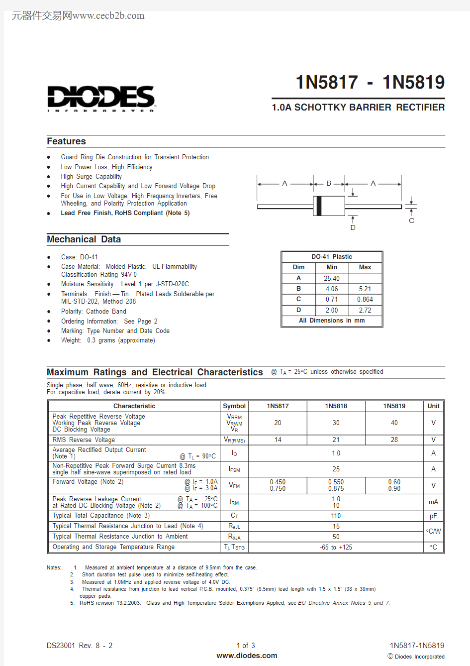
1N5817 - 1N5819
1.0A SCHOTTKY BARRIER RECTIFIER
Maximum Ratings and Electrical Characteristics
@ T A = 25°C unless otherwise specified
·Guard Ring Die Construction for Transient Protection ·Low Power Loss, High Efficiency ·High Surge Capability
·High Current Capability and Low Forward Voltage Drop ·For Use in Low Voltage, High Frequency Inverters, Free Wheeling, and Polarity Protection Application ·
Lead Free Finish,RoHS Compliant (Note 5)
Mechanical Data
·Case: DO-41
·Case Material: Molded Plastic. UL Flammability Classification Rating 94V-0
·Moisture Sensitivity: Level 1 per J-STD-020C
·Terminals: Finish ?Tin. Plated Leads Solderable per MIL-STD-202, Method 208·Polarity: Cathode Band
·Ordering Information: See Page 2·Marking: Type Number and Date Code ·
Weight: 0.3 grams (approximate)
Single phase, half wave, 60Hz, resistive or inductive load.For capacitive load, derate current by 20%.
Notes: 1. Measured at ambient temperature at a distance of 9.5mm from the case.
2. Short duration test pulse used to minimize self-heating effect.
3. Measured at 1.0MHz and applied reverse voltage of
4.0V DC.
4. Thermal resistance from junction to lead vertical P.C.B. mounted, 0.375" (9.5mm) lead length with 1.5 x 1.5" (38 x 38mm)
copper pads.
5.RoHS revision 13.2.2003. Glass and High Temperature Solder Exemptions Applied, see EU Directive Annex Notes 5 and 7.
Notes: 6. For packaging details, visit our website at https://www.doczj.com/doc/fc16861778.html,/datasheets/ap02008.pdf
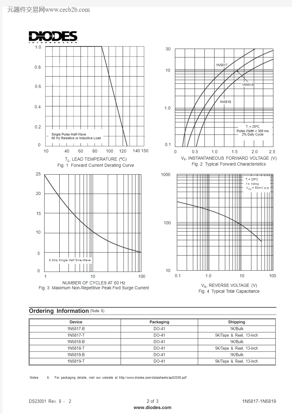
I ,A V E R A G E O U T P U T C U R R E N T (A )
(A V )00.2
0.4
0.6
0.8
1.0
10
40
60
80
100
120
140150
T ,LEAD TEMPERATURE (oC)Fig.1Forward Current Derating Curve
L
10
100
1000
0.1
1.0
10
100
C ,T O T A L C A P A C I T A N C E (p F )
T V ,REVERSE VOLTAGE (V)Fig.4
Typical Total Capacitance
R 0
5
10
15
20
25
1
10
100
I ,P E A K F O R W A R D S U R G E C U R R E N T (A )
F S M NUMBER OF CYCLES AT 60
Hz
Fig.3Maximum Non-Repetitive Peak Fwd Surge Current
0.1
1.0
10
30
0.5
1.0
1.5
2.0
2.5
I ,N S T A N T A N E O U S F O R W A R D C U R R E N T (A )
F V ,INSTANTANEOUS FORWARD VOLTAGE (V)
Fig.2Typical Forward Characteristics
F
Ordering Information
(Note 6)