机械外文文献及翻译
- 格式:doc
- 大小:459.50 KB
- 文档页数:13
翻译部分英文原文High-speed machining and demand for the development ofHigh-speed machining is contemporary advanced manufacturing technology an important component of the high-efficiency, High-precision and high surface quality, and other features. This article presents the technical definition of the current state of development of China's application fields and the demand situation.High-speed machining is oriented to the 21st century a new high-tech, high-efficiency, High-precision and high surface quality as a basic feature, in the automobile industry, aerospace, Die Manufacturing and instrumentation industries gained increasingly widespread application, and has made significant technical and economic benefits. contemporary advanced manufacturing technology an important component part.HSC is to achieve high efficiency of the core technology manufacturers, intensive processes and equipment packaged so that it has a high production efficiency. It can be said that the high-speed machining is an increase in the quantity of equipment significantly improve processing efficiency essential to the technology. High-speed machining is the major advantages : improve production efficiency, improve accuracy and reduce the processing of cutting resistance.The high-speed machining of meaning, at present there is no uniform understanding, there are generally several points as follows : high cutting speed. usually faster than that of their normal cutting 5 -10 times; machine tool spindle speed high, generally spindle speed in -20000r/min above 10,000 for high-speed cutting; Feed at high velocity, usually 15 -50m/min up to 90m/min; For different cutting materials and the wiring used the tool material, high-speed cutting the meaning is not necessarily the same; Cutting process, bladed through frequency (Tooth Passing Frequency) closer to the "machine-tool - Workpiece "system the dominant natural frequency (Dominant Natural Frequency), can be considered to be high-speed cutting. Visibility high-speed machining is a comprehensive concept.1992. Germany, the Darmstadt University of Technology, Professor H. Schulz in the 52th on the increase of high-speed cutting for the concept and the scope, as shown in Figure 1. Think different cutting targets, shown in the figure of the transition area (Transition), to be what is commonly called the high-speed cutting, This is also the time of metal cutting process related to the technical staff are looking forward to, or is expected to achieve the cutting speed.High-speed machining of machine tools, knives and cutting process, and other aspects specific requirements. Several were from the following aspects : high-speed machining technology development status and trends.At this stage, in order to achieve high-speed machining, general wiring with high flexibility of high-speed CNC machine tools, machining centers, By using a dedicated high-speed milling, drilling. These equipment in common is : We must also have high-speed and high-speed spindle system feeding system, Cutting can be achieved in high-speed process. High-speed cutting with the traditional cutting the biggest difference is that "Machine-tool-workpiece" the dynamic characteristics of cutting performance is stronger influence. In the system, the machine spindle stiffness, grip or form, a long knife set, spindle Broach, torque tool set, Performance high-speed impact are important factors.In the high-speed cutting, material removal rate (Metal Removal Rate, MRR), unit time that the material was removed volume, usually based on the "machine-tool-workpiece" whether Processing System "chatter." Therefore, in order to satisfy the high-speed machining needs, we must first improve the static and dynamic stiffness of machine spindle is particularly the stiffness characteristics. HSC reason at this stage to be successful, a very crucial factor is the dynamic characteristics of the master and processing capability.In order to better describe the machine spindle stiffness characteristics of the project presented new dimensionless parameter - DN value, used for the evaluation of the machine tool spindle structure on the high-speed machining of adaptability. DN value of the so-called "axis diameter per minute speed with the product." The newly developed spindle machining center DN values have been great over one million. To reduce the weight bearing, but also with an array of steel products than to the much more light ceramic ball bearings; Bearing Lubrication most impressive manner mixed with oil lubrication methods. In the field of high-speed machining. have air bearings and the development of magnetic bearings and magnetic bearings and air bearings combined constitute the magnetic gas / air mixing spindle.Feed the machine sector, high-speed machining used in the feed drive is usually larger lead, multiple high-speed ball screw and ball array of small-diameter silicon nitride (Si3N4) ceramic ball, to reduce its centrifugal and gyroscopic torque; By using hollow-cooling technology to reduce operating at high speed ball screw as temperature generated by the friction between the lead screw and thermal deformation.In recent years, the use of linear motor-driven high-speed system of up to'' Such feed system has removed the motor from workstations to Slide in the middle of all mechanical transmission links, Implementation of Machine Tool Feed System of zero transmission. Because no linear motor rotating components, from the role of centrifugal force, can greatly increase the feed rate. Linear Motor Another major advantage of the trip is unrestricted. The linear motor is a very time for a continuous machine shop in possession of the bed. Resurfacing of the very meeting where avery early stage movement can go, but the whole system of up to the stiffness without any influence. By using high-speed screw, or linear motor can greatly enhance machine system of up to the rapid response. The maximum acceleration linear motors up to 2-10G (G for the acceleration of gravity), the largest feed rate of up to 60 -200m/min or higher.2002 world-renowned Shanghai Pudong maglev train project of maglev track steel processing, Using the Shenyang Machine Tool Group Holdings Limited McNair friendship company production plants into extra-long high-speed system for large-scale processing centers achieve . The machine feeding system for the linear guide and rack gear drive, the largest table feed rate of 60 m / min, Quick trip of 100 m / min, 2 g acceleration, maximum speed spindle 20000 r / min, the main motor power 80 kW. X-axis distance of up to 30 m, 25 m cutting long maglev track steel error is less than 0.15 mm. Maglev trains for the smooth completion of the project provided a strong guarantee for technologyIn addition, the campaign machine performance will also directly affect the processing efficiency and accuracy of processing. Mold and the free surface of high-speed machining, the main wiring with small cut deep into methods for processing. Machine requirements in the feed rate conditions, should have high-precision positioning functions andhigh-precision interpolation function, especially high-precision arc interpolation. Arc processing is to adopt legislation or thread milling cutter mold or machining parts, the essential processing methods. Cutting Tools Tool Material developmenthigh-speed cutting and technological development of the history, tool material is continuous progress of history. The representation ofhigh-speed cutting tool material is cubic boron nitride (CBN). Face Milling Cutter use of CBN, its cutting speed can be as high as 5000 m / min, mainly for the gray cast iron machining. Polycrystalline diamond (PCD) has been described as a tool of the 21st century tool, It is particularly applicable to the cutting aluminum alloy containing silica material, which is light weight metal materials, high strength, widely used in the automobile, motorcycle engine, electronic devices shell, the base, and so on. At present, the use of polycrystalline diamond cutter Face Milling alloy, 5000m/min the cutting speed has reached a practical level. In addition ceramic tool also applies to gray iron of high-speed machining; Tool Coating : CBN and diamond cutter, despite good high-speed performance, but the cost is relatively high. Using the coating technology to make cutting tool is the low price, with excellent mechanical properties, which can effectively reduce the cost. Now high-speed processing of milling cutter, with most of the wiring between the Ti-A1-N composite technology for the way of multi-processing, If present in the non-ferrous metal or alloy material dry cutting, DLC (Diamond Like Carbon) coating on thecutter was of great concern. It is expected that the market outlook is very significant;Tool clamping system : Tool clamping system to support high-speed cutting is an important technology, Currently the most widely used is a two-faced tool clamping system. Has been formally invested as a commodity market at the same clamping tool system are : HSK, KM, Bigplus. NC5, AHO systems. In the high-speed machining, tool and fixture rotary performance of the balance not only affects the precision machining and tool life. it will also affect the life of machine tools. So, the choice of tool system, it should be a balanced selection of good products.Process ParametersCutting speed of high-speed processing of conventional shear velocity of about 10 times. For every tooth cutter feed rate remained basically unchanged, to guarantee parts machining precision, surface quality and durability of the tool, Feed volume will also be a corresponding increase about 10 times, reaching 60 m / min, Some even as high as 120 m / min. Therefore, high-speed machining is usually preclude the use of high-speed, feed and depth of cut small cutting parameters. Due to the high-speed machining cutting cushion tend to be small, the formation of very thin chip light, Cutting put the heat away quickly; If the wiring using a new thermal stability better tool materials and coatings, Using the dry cutting process for high-speed machining is the ideal technology program. High-speed machining field of applicationFlexible efficient production lineTo adapt to the needs of new models, auto body panel molds andresin-prevention block the forming die. must shorten the production cycle and reduce the cost of production and, therefore, we must make great efforts to promote the production of high-speed die in the process. SAIC affiliated with the company that : Compared to the past, finishing, further precision; the same time, the surface roughness must be met, the bending of precision, this should be subject to appropriate intensive manual processing. Due to the extremely high cutting speed, and the last finishing processes, the processing cycle should be greatly reduced. To play for machining centers and boring and milling machining center category represented by the high-speed machining technology and automatic tool change function of distinctions Potential to improve processing efficiency, the processing of complex parts used to be concentrated as much as possible the wiring process, that is a fixture in achieving multiple processes centralized processing and dilute the traditional cars, milling, boring, Thread processing different cutting the limits of technology, equipment and give full play to the high-speed cutting tool function, NC is currently raising machine efficiency and speed up product development in an effective way. Therefore, the proposed multi-purpose tool of the new requirements call for a tool to complete different partsof the machining processes, ATC reduce the number of ATC to save time, to reduce the quantity and tool inventory, and management to reduce production costs. More commonly used in a multifunctional Tool, milling, boring and milling, drilling milling, drilling-milling thread-range tool. At the same time, mass production line, against the use of technology requires the development of special tools, tool or a smart composite tool, improve processing efficiency and accuracy and reduced investment. In the high-speed cutting conditions, and some special tools can be part of the processing time to the original 1 / 10 below, results are quite remarkable. HSC has a lot of advantages such as : a large number of materials required resection of the workpiece with ultrafine, thin structure of the workpiece, Traditionally, the need to spend very long hours for processing mobile workpiece and the design of rapid change, short product life cycle of the workpiece, able to demonstrate high-speed cutting brought advantages.中文译文高速切削加工的发展及需求高速切削加工是当代先进制造技术的重要组成部分,拥有高效率、高精度及高表面质量等特征。

机械外文文献翻译Overall position of Agricultural Mechanization inTurkeyAgricultural equipment and machinery are the indispensable part of agricultural activities. If these instruments, which are used in various stages of production, are not used properly, there may be some problems. So, how can we use them properly ? As the proverb goes, “It is the want of care that makes the field bare”. They return the money and efforts invested in them if they are maintained well.Ploughs, which were being used in our country up until recently, resemble those ploughs of the various tribes that lived in Anatolia long time ago. It is becauseone society gets use of societies that lived before. Some of the black ploughs that were being used up until recently resemble the ploughs that had been used in the ancient Rome.The first agricultural school was established in the Ottoman Empire in 1846. The first domestic heavy ploughs was manufactured i n Izmir 90 years ago, andtractor was introduced 80 years ago. However, it was only the foundation of the Republic that the tractor began to be used in agricultural activities. Agricultural mobilization began with modern agricultural practices in the Atatürk Forest Farm, which was founded by the Great Atatürk. Use of modern agricultura l equipment was encouraged,workshops and factories were established, and agricultural machinery was manufactured. Introduction of tractor and particularly its use in agricultural production began in 1938. In those years, tractor use in State Production Farms increased, and farmers recognized the benefits of tractor in agricultural productivity and labor. State production farms became places which clearly showed the importance of agricultural mechanization.Agricultural mechanization is a production technology which enables the appropriate use of energy and equipment required for high production in agricultural area.Warehousing, transporting and marketing the products have become faster and more economic with the help of agricultural mechanization.Tractor is the basic equipment that enables the use of other agricultural equipment. These equipment items are also produced in Turkey. As tractor and other mechanization equipment are expensive, they should be used in a way to achieve the highest productivity and managed by informed and efficient people.Agricultural production in Turkey is Cereal-BasedAgricultural production in Turkey is cereal-based. There are serious nutrition problems in more than the half of the developing countries. Every year, millions of people die of hunger. For this reason, agricultural production is highly important. Turkey is out of it’s available planting areas. They do not have any new places left for plantation. The only thing they can do is to increase productivity. Inorder to increase productivity, they need to use some imputs. The only way to increase these inputs such as fertilizers, chemicals, irrigation and high quality seedling is agricultural mechanization. It is achieved through ploughing the soil in the right time, planting with a particular plantation row and particular distance in order to utilize equally from all parts of soil, applying chemicals and fertilizers at the requested time and amount, harvesting in a short period and without loss of any grains, and storing the product.Necessary support is given to Turkey’s companiesAgricultural mechanization tools are expensive. However, if they are maintained well and used economically, they return their cost. State provides some opportunities such as low-interest rates for the procurement of Agricultural Mechanization Machineries. The equipment and machinery, which can be purchased with credits, are examined by theunits established by the Ministry of Agriculture and Rural Affairs to be approved for the agricultural technique. In these institutions, allkinds of tools and machinery, including tractors, go under various tests. It is determined if these machines are appropriate for Turkey’s environment. Necessary support is given to Turkey’s companies and farmers in order to remove the deficiencies determined.As for the maintenance of these equipment and machinery, it is agreat chance that via the improvement of technology, Turkey’s producers are provided withopportunities that will help them in agricultural activities. According to researches,if the maintenance of a machine is done right and on time, purchasing cost decreasedby 1/5.农业机械化在土耳其的整体地位农业设备和机械在农业活动中是不可或缺的组成部分。
常用研磨机外文文献翻译、中英文翻译、外文翻译Grinding machine is a crucial n processing method that offers high machining accuracy and can process a wide range of materials。
It is suitable for almost all kinds of material processing。
and can achieve very high n and shape accuracy。
even reaching the limit。
The machining accuracy of grinding device is simple and does not require complex ___.2.Types of Grinding MachinesGrinding machines are mainly used for n grinding of workpiece planes。
cylindrical workpiece surfaces (both inside and outside)。
tapered faces inside。
spheres。
thread faces。
and other types of ___ grinding machines。
including disc-type grinding machines。
shaft-type grinding machines。
ic grinding machines。
and special grinding machines.3.Disc-type Grinding MachineThe disc-type grinding machine is a type of grinding machine that uses a grinding disc to grind the ___。
附录翻译部分Lathe and TurningThe Lathe and Its ConstructionA lathe is a machine tool used primarily for producing surfaces of revolution flat edges. Based on their purpose ,construction , number of tools that can simultaneously be mounted , and degree of automation ,lathes or, more accurately, lathe-type machine tools can be classified as follows:(1) Engine lathes(2) Toolroom lathes(3) Turret lathes(4) Vertical turning and boring mills(5) Automatic lathes(6) Special-purpose lathesIn spite of that diversity of lathe-type machine tools, they all have all have common features with respect to construction and principle of operation .These features can best be illustrated by considering the commonly used representative type, the engine lathe. Following is a description of each of the main elements of an engine lathe , which is shown in Fig.11.1.Lathe bed . The lathe bed is the main frame , involving a horizontal beam on two vertical supporis. It is usually made of grey or nodular cast iron to damp vibrations and is made by casting . It has guideways to allow the carriage to slide easily lengthwise. The height of the lathe bed should be appropriate to enable the technician to do his or her jib easily and comfortably.Headstock. The headstock is fixed at the left hand side of the lathe bed and includes the spindle whose axis is parallel to the guideways (the silde surface of the bed) . The spindle is driven through the gearbox , which is housed within the headstock. The function of the gearbox is to provide a number of different spindle speeds (usually 6 up to 18 speeds) . Some modern lathes have headstocks with infinitely variable spindle speeds, which employ frictional , electrical , or hydraulic drives.The spindle is always hollow , I .e ,it has a through hole extending lengthwise. Bar stocks can be fed througth that hole if continous production is adopted . A lso , that hole has a taperedsurface to allow mounting a plain lathe center . The outer surface of the spindle is threaded to allow mounting of a chuck , a face plate , or the like .Tailstock . The tailstock assembly consists basically of three parts , its lower base, an intermediate part, and the quill . The lower base is a casting that can slide on the lathe bed along the guidewayes , and it has a clamping device to enable locking the entire tailstock at any desired location , depending upon the length of the workpiece . The intermediate parte is a casting that can be moved transversely to enable alignment of the axis of the the tailstock with that of the headstock . The third part, the quill, is a hardened steel tube, which can be moved longitudinally in and out of the intermediate part as required . This is achieved through the use of a handwheel and a screw , around which a nut fixed to the quill is can be locked at any point along its travel path by means of a clamping device.The carriage. The main function of the carriage is mounting of the cutting tools and generating longitudinal and /or cross feeds. It is actually an H-shaped block that slides on the lathe bed between the headstock and tailstock while being guided by the V-shaped guideways of the bed . The carriage can be moved either manually or mechanically by means of the apron and either the feed rod or the lead screw.When cutting screw threads, power is provided to the gearbox of the apron by the lead screw. In all other turning operations, it is the feed rod that drives the carriage. The lead screw goes through a pair o half nuts , which are fixed to the rear of the apron . When actuating a certain lever, the half nuts are clamped together and engage with the rotating lead screw as a single nut, which is fed , together with carriage, along the bed . when the lever is disengaged , the half nuts are released and the carriage stops. On the other hand , when the feed rod is used, it supplies power to the apron through a wrom gear . The latter is keyed to feed rod and travels with the apron along the feed rod , which has a keyway extending to cover its whole length. A modern lathe usually has a quick-change gearbox located under the headstock and driven from the spindle through a train of gears. It is connected to both the feed rod and the lead screw and enables selecting a variety of feeds easily and rapidly by simply shifting the appropriate levers, the quick-change gearbox is employed in plain turning, facing and thread cutting operations. Since that gearbox is linked to spindle, the distance that the apron (and the cutting tool) travels for each revolution of the spindle can be controlled and is referred to as the feed.Lathe Cutting ToolsThe shape and geometry of the lathe tools depend upon the purpose for which they are employed. Turning tools can be classified into tow main groups,namely,external cutting tools andinternal cutting tools , Each of these groups include the following types of tools: Turning tools. Turing tools can be either finishing or rough turning tools . Rough turning tools have small nose radii and are used for obtaining the final required dimensions with good surface finish by marking slight depth of cut . Rough turning tools can be right –hand or left-hand types, depending upon the direction of feed. They can have straight, bent, or offset shanks.Facing tools . Facing tools are employed in facing operations for machining plane side or end surfaces. There are tools for machining left-hand-side surfaces and tools for right-hand-side surfaces. Those side surfaces are generated through the use of the cross feed, contrary to turning operations, where the usual longitudinal feed is used.Cutoff tools. Cutoff tools ,which are sometimes called parting tools, serve to separate the workpiece into parts and/or machine external annual grooves.Thread-cutting tools. Thread-cutting tools have either triangular, square, or tranpezoidal cutting edges, depending upon the cross section of the desired thread .Also , the plane angles of these tools must always be identical to those of the thread forms. Thread-cutting tools have straight shanks for external thread cutting and are of the bent-shank type when cutting internal threads .Form tools. Form tools have edges especially manufactured to take a certain form, which is opposite to the desired shape of the machined workpiece . An HSS tools is usually made in the form of a single piece ,contrary to cemented carbides or ceramic , which are made in the form of tipes. The latter are brazed or mechanically fastened to steel shanks. Fig.1indicates an arrangement of this latter type, which includes the carbide tip , the chip breaker ,the pad ,the clamping screw (with a washer and a nut ) , and the shank.. As the name suggests, the function of the chip breaker is to break long chips every now and then , thus preventing the formation of very long twisted ribbons that may cause problems during the machining operations . The carbide tips ( or ceramic tips ) can have different shapes, depending upon the machining operations for which they are to be employed . The tips can either be solid or with a central through hole ,depending on whether brazing or mechanical clamping is employed for mounting the tip on the shank.Fig.1Lathe OperationsIn the following section , we discuss the various machining operations that can be performed on a conventional engine lathe. It must be borne in mind , however , that modern computerized numerically controlled lathes have more capabiblities and do other operations ,such as contouring , for example . Following are conventional lathe operations.Cylindrical turning . Cylindrical turning is the the simplest and the most common of all lathe operations . A single full turn of the workpiece generate a circle whose center falls on the lathe axis; this motion is then reproduced numerous times as a result of the axial feed motion of the tool. The resulting machining marks are , therefore ,a helix having a very small pitch, which is equal to the feed . Consequently , the machined surface is always cylindrical.The axial feed is provided by the carriage or the compound rest , either manually or automatically, whereas the depths of cuts is controlled by the cross slide . In roughing cuts , it is recommended that large depths of cuts (up to 0.25 in. or 6 mm, depending upon the workpiece material) and smaller feeds would be used. On the other hand , very fine feeds, smaller depth of cut (less than 0.05in. , or 0.4 mm) , and high cutting speeds are preferred for finishing cuts.Facing . The result of a facing operation is a flat surface that is either the whole end surface of the workpiece or an annular intermediate surface like a shoulder . During a facing operation ,feed is provided by the cross slide, whereas the depth of cut is controlled by the carriage or compound rest . Facing can be carried out either from the periphery in ward or from the center of the workpiece outward . It is obvious that the machining marks in both cases tack the form of a spiral. Usually, it is preferred to clamp the carriage during a facing operation, since the cutting force tends to push the tool ( and , of course , the whole carriage ) away from the workpiece . In most facing operations , the workpiece is held in a chuck or on a face plate.Groove cutting. In cut-off and groove-cutting operations ,only cross feed of the tool isemployed. The cut-off and grooving tools , which were previously discussed, are employed.Boring and internal turning . Boring and internal are performed on the internal surfaces by a boring bar or suitable internal workpiece is solid, a drilling operation must be performed first . The drilling tool is held in the tailstock, and latter is then fed against the workpiece.Taper turning . Taper turning is achieved by driving the tool in a direction that is not paralled to the lathe axis but inclined to it with an angle that is equal to the desired angle of the taper . Following are the different methods used in taper-turning practice:(1)Rotating the disc of the compound rest with an angle to half the apex angle of the cone . Feed is manually provided by cranking the handle of the compound rest . This method is recommended for taper turning of external and internal surfaces when the taper angle is relatively large.(2)Employing special form tools for external , very short ,conical surfaces . The width of the workpiece must be slightly smaller than that of the tool ,and the workpiece is usually held in a chuck or clamped on a face plate . I n this case , only the cross feed is used during the machining process and the carriage is clamped to the machine bed .(3)Offsetting the tailstock center . This method is employed for esternal tamper turning of long workpiece that are required to have small tamper angles (less than 8 ) . The workpiece is mounted between the two centers ; then the tailstock center is shifted a distance S in the direction normal to the lathe axis.(4)Using the taper-turning attachment . This method is used for turning very long workpoece , when the length is larger than the whole stroke of the compound rest . The procedure followed in such cases involves complete disengagement of the cross slide from the carriage , which is then guided by the taper-turning attachment . During this process, the automatic axial feed can be used as usual . This method is recommend for very long workpiece with a small cone angle , i.e. , 8 through 10 .Thread cutting . When performing thread cutting , the axial feed must be kept at a constant rate , which is dependent upon the rotational speed (rpm) of the workpiece . The relationship between both is determined primarily by the desired pitch of the thread to be cut .As previously mentioned , the axial feed is automatically generated when cutting a thread by means of the lead screw , which drives the carriage . When the lead screw rotates a single revolution, the carriage travels a distance equal to the pitch of the lead screw rotates a single revolutional speed of the lead screw is equal to that of the spindle ( i. e . , that of the workpiece ),the pitch of the resulting cut thread is exactly to that of the lead screw . The pitch of the resulting thread being cut therefore always depends upon the ratio of the rotational speeds of the lead scew and the spindle :workpiece of pitch screw lead the of Pitch Desired = screwlead of workpiece the of rpm rpm = spindle-to-carriage gearing ratio This equation is usefully in determining the kinematic linkage between the lathe spindle and the lead screw and enables proper selection of the gear train between them .In thread cutting operations , the workpiece can either be held in the chuck or mounted between the two lathe centers for relatively long workpiece . The form of the tool used must exactly coincide with the profile the thread to be cut , I . e . , triangular tools must be used for triangular threads , and so on .Knurling . knurling is mainly a forming operation in which no chips are prodyced . Tt involves pressing two hardened rolls with rough filelike surfaces against the rotating workpiece to cause plastic deformation of the workpiece metal.Knurling is carried out to produce rough , cylindrical ( or concile )surfaces , which are usually used as handles . Sometimes , surfaces are knurled just for the sake of decoration ; there are different types of patterns of knurls from which to choose .Cutting Speeds and FeedsThe cutting speed , which is usually given in surface feet per minute (SFM), is the number of feet traveled in circumferential direction by a given point on the surface (being cut ) of the workpiece in one minute . The relationship between the surface speed and rpm can be given by the following equation :SMF=πDNWhereD= the diameter of the workpiece in feetN=the rpmThe surface cutting speed is dependent primarily upon the machined as well as the material of the cutting and can be obtained from handbooks , information provided by cutting tool manufacturera , and the like . generally , the SFM is taken as 100 when machining cold-rolled or mild steel ,as 50 when machining tougher metals , and as 200 when machining sofer materials . For aluminum ,the SFMis usually taken as 400 or above . There are also other variables that affect the optimal value of the surface cutting speed . These include the toolgeometry, the type of lubricant or coolant , the feed , and the depth of cut . As soon as the cutting sped is decided upon , the rotational speed (rpm) of the spindle can be obtained as follows :N = DSFW π The selection of a suitable feed depends upon many factors , such as the required surface finish , the depth of cut , and the geometry of the tool used . Finer feeds produce better surface finish ,whereas higher feeds reduce the machining time during which the tool is in direct contact with the workpiece . Therefore ,it is generally recommended to use high feeds for roughing operations and finer feeds for finishing operations. Again, recommend values for feeds , which can be taken as guidelines , are found in handbooks and information booklets provided by cutting tool manufacturers.Here I want to introduce the drilling:Drilling involves producing through or blind holes in a workpiece by forcing a tool , which rotates around its axis , against the workpiece .Consequently , the range of cutting from that axis of rotation is equal to the radius of the required hole .In practice , two symmetrical cutting edges that rotate about the same axis are employed .Drilling operations can be carried out by using either hand drills or drilling machines . The latter differ in size and construction . nevertheless , the tool always rotates around its axis while the workpiece is kept firmly fixed . this is contrary to drilling on a lathe .Cutting Tool for Drilling OperationsIn drilling operations , a cylindrical rotary-end cutting , called a drill , is employed . The drill can have either one or more cutting edges and corresponding flutes , which can be straight or helical . the function of the flutes is to provide outlet passages for the chips generated during the drilling operation and to allow lubricants and coolants to reach the cutting edges and the surface being machined . Following is a survey of the commonly used drills.Twist drill . The twist drill is the most common type of drill .It has two cutting edges and two helical flutes that continue over the length of the drill body , The drill also consist of a neck and a shake that can be either straight or tapered .In the latter case , the shank is fitted by the wedge action into the tapered socket of the spindle and has a tang , which goes into a slot in the spindle socket ,thus acting as a solid means for transmitting rotation . On the other hand , straight –shank drills are held in a drill chuck that is , in turn , fitted into the spindle socket in the same way as tapered shank drills.The two cutting edges are referred to as the lips , and are connected together by a wedge , which is a chisel-like edge . The twist drill also has two margins , which enable proper guidance and locating of the drill while it is in operation . The tool point angle (TPA) is formed by the lips and is chosen based on the properties of the material to be cut . The usual TAP for commercial drills is 118 , which is appropriate for drilling low-carbon steels and cast irons . For harder and tougher metals , such as hardened steel , brasss and bronze , larger TPAs (130 OR 140 ) give better performance . The helix angle of the flutes of the commonly used twist drills ranges between 24 and 30 . When drilling copper or soft plastics , higher values for the helix angle are recommended (between 35 and 45).Twist drills are usually made of high speed steel ,although carbide tipped drills are also available . The size of twist drills used in industrial range from 0.01 up to 3.25 in . (i.e.0.25 up to 80 mm ) .Core drills . A core drill consists of the chamfer , body , neck ,and shank . This type of drill may be have either three or four flutes and an equal number of margins , which ensure superior guidance , thus resulting in high machining accuracy . It can also be seen in Fig 12.2 that a core drill has flat end . The chamfer can have three or four cutting edges or lips , and the lip angle may vary between 90 and 120 . Core drills are employed for enlarging previously made holes and not for originating holes . This type of drill is characterized by greater productivity , high machining accuracy , and superior quality of the drilled surfaces .Gun drills . Gun drills are used for drilling deep holes . All gun drills are straight fluted , and each has a single cutting edge . A hole in the body acts as a conduit to transmit coolant under considerable pressure to the tip of the drill .There are two kinds of gun drills , namely , the center cut gun drill used for drilling blind holes and the trepanning drill . The latter has a cylindrical groove at its center , thus generating a solid core , which guides the tool as it proceeds during the drilling operation.Spade drills . Spade drills are used for drilling large holes of 3.5 in .(90 mm ) or more . Their design results in a marked saving in cost of the tool as well as a tangible reduction in its weight , which facilitates its handling . moreover , this type of drill is easy to be ground .[13]车床和车削车床及它的结构车床是一个主要用来生产旋转表面和端面的机床。
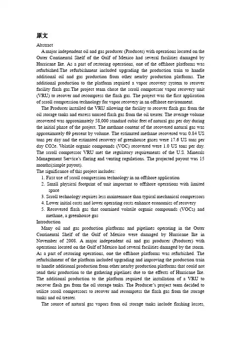
原文AbstractA major independent oil and gas producer (Producer) with operations located on the Outer Continental Shelf of the Gulf of Mexico had several facilities damaged by Hurricane Ike. As a part of restoring operations, one of the offshore platforms was refurbished.The refurbishment included upgrading the production train to handle additional oil and gas production from other nearby production platforms. The additional production to the platform required a vapor recovery system to recover facility flash gas.The project team chose the scroll compressor vapor recovery unit (VRU) to recover and recompress the flash gas. The project was the first application of scroll compression technology for vapor recovery in an offshore environment.The Producer installed the VRU allowing the facility to recover flash gas from the oil storage tanks and excess unused flash gas from the oil treater. The average volume recovered was approximately 58,000 standard cubic feet of natural gas per day during the initial phase of the project. The methane content of the recovered natural gas was approximately 69 percent by volume. The estimated methane recovered was 0.84 US tons per day and the estimated recovery of greenhouse gases were 17.6 US tons per day CO2e. V olatile organic compounds (VOC) recovered were 1.0 US tons per day. The scroll compressor VRU met the regulatory requirements of the U.S. Minerals Management Service’s flaring and venting regulations. The projected payout was 15 months(simple payout).The significance of this project includes:1. First use of scroll compression technology in an offshore application2. Small physical footprint of unit important to offshore operations with limitedspace3. Scroll technology requires less maintenance than typical mechanical compressors4. Lower initial costs and lower operating costs enhance economics of recovery5. Recovered flash gas that contained volatile organic compounds (VOCs) andmethane, a greenhouse gasIntroductionMany oil and gas production platforms and pipelines operating in the Outer Continental Shelf of the Gulf of Mexico were damaged by Hurricane Ike in November of 2008. A major independent oil and gas producer (Producer) with operations located on the Gulf of Mexico had several facilities damaged by the storm. As a part of restoring operations, one the offshore platforms was refurbished. The refurbishment of the platform included upgrading and improving the production train to handle additional production from other nearby production platforms that could not send their production to the gathering pipelines due to the effects of Hurricane Ike. The additional production to the platform required the installation of a VRU to recover flash gas from the oil storage tanks. The Producer’s project team decided to utilize scroll compressors to recover and recompress the flash gas from the storage tanks and oil treater.The source of natural gas vapors from oil storage tanks include flashing losses,working losses and breathing losses. Flashing for a pressure vessel (e.g., separator, heater treater) or oil storage tank occurs when the crude oil or condensate with dissolved gases moves from a higher pressure to a lower pressure. As the pressure of the oil drops some of the lighter components dissolved in the oil are released or “flashed.” Working losses are due to displacement of the natural gas vapors within the storage tank vapor space as a tank is filled. Breathing losses are due to displacement of natural gas vapor within the storage tank vapor space due to changes in the tank temperature and pressure throughout the day. For this paper we refer to the vent gas from the oil storage tanks collectively as flash gas.Often flash gases from offshore production platforms are either vented directly to the atmosphere or burned by a flare. Historically VRUs have been used to recover flash gas when there is sufficient quantity to justify the investment and to meet air emission standards. The typical type of vapor recovery compressors used for vent flash gas has been natural gas driven rotary screw compressors and rotary vane compressors.The United States Minerals Management Service (MMS) is the regulatory agency with jurisdiction over venting of natural gas in the central and western areas of the Gulf of Mexico. MMS regulations require a facility to recover natural gas volumes over 50,000 standard cubic feet per day rather than venting directly to the atmosphere or burning in a flare. For offshore production platforms, deck space requirements are a significant consideration for vapor recovery units. To accommodate this limitation, the scroll compressor package has a footprint one-third the size of a traditional VRUs used. In addition, lower overall maintenance costs were a significant factor in the decision to utilize scroll compressor technology. The scroll compressor requires oil changes once per year compared to quarterly for the typical mechanical compressor. Equipment used in the offshore environment required capital upgrades to the typical onshore compression package due to the saltwater corrosive environment and additional safety controls required for operating offshore. For this project the standard onshore VRU was upgraded to meet specifications for the offshore conditions and regulations.Description and Application of Equipment and ProcessesScroll Compression Technology.Scroll compression technology is a positive displacement machine that uses two interleaved spiral-shaped scrolls to compress natural gas. With scroll compression technology, one of the scrolls is fixed, while the other orbits eccentrically, thereby trapping and pumping or compressing gas between through successively smaller scroll volume “pockets” until the gas reaches maximum pressure at the center. At the center, the gas is released through a discharge point in the fixed scroll. Compression is continuous since during orbit of the orbiting scroll, multiple gas pockets are compressed simultaneously.The driver for the compressor is an electric motor. The scroll compressor is a hermetic compressor designed for use with high-pressure refrigerants. It has a broad range of operation and is intrinsically leak free. Scroll compressor technology has been widely used in cooling system applications.The scroll compressor VRU installed had a horizontal design that has a low profile, low noise, low vibration, and uses variable speed control motors. Depending on the application, the range of inlet pressures of gas to the scroll compressor VRUs may vary from -10.4 to 101.3 pounds per square inch gage and the discharge pressures can range from 43.5 to 363 pounds per square inch gage. The compression ratio ranges from 3 to 15.Scroll compression technology has been used in oil and gas vapor recovery applications since 2004.Application of Scroll Technology.In May of 2009, COMM and the Producer began working together to modify a typical onshore scroll compressor VRU for the platform that was damaged and being refurbished.The scroll compressor VRU consisted of two stacked modules each 8-foot long by 4-foot wide by 4-foot high steel skids each with an inlet gas scrubber. Each module contained two 15-horsepower scroll compressors and an aftercooler. Each module also included a control panel with Programmable Logic Control (PLC) and variable frequency drive (VFD). The design recovery capacity of this twin module package used was 200,000 standard cubic feet per day.A suction line connected to the oil storage tanks’ common vent and to the oil treater (i.e., heater treater) vent was installed to the inlet scrubber of the scroll compressor VRU. The suction line to the oil treater was used to collect excess gas from the oil treater that was not used as platform fuel gas. A flow meter was placed on the suction line prior to the inlet of the scroll compressor VRU to measure the amount of natural gas recovered. The discharge of the scroll compressor package was piped to the suction separator/scrubber of the onsite main compressor. This main compressor compresses natural gas for ultimate injection into the sales pipeline.A purge gas system was installed and used to recycle gas through the scroll compressor VRU when there is insufficient pressure from flash gas in the storage tanks. The purpose of the purge gas system is to keep VRU operating to maintain the scroll compressor’s oil temperature at a minimum of 235 degrees Fahrenheit. By maintaining the oil temperature at or above 235 degrees F, the flash gas will remain in a gas phase.As a safety measure, a blanket gas system was installed on the storage tanks to maintain approximately 0.5 ounce per square inch of pressure on the tanks to keep oxygen from entering the tanks.Figure 1 contains a simplified process flow for the VRU.The control panels with VFD’s were located in the motor control center (MCC) and wiring was run to the scroll compressor VRU which was located on a lower deck of the platform.Functionally, the scroll compressor operates normally in the recycle mode at 2400 revolutions per minute (rpm). When the pressure builds in the oil storage tanks, a pressure transmitter sends a signal enabling the speed of the compressor to increase to 4800 rpms and the flash gas is recovered and compressed. Once the flash gas from the storage tanks is recovered and the pressure drops in the storage tanks, the VFD rampsthe compressor speed down to 2400 rpms. Then the VRU is in recycle mode again. Any liquids recovered by the gas scrubber are pumped back to the oil storage tanks. Modifications to VRU Package.To meet offshore specification, the structural components of the scroll compressor package were already hot dipped galvanized and suitable for offshore installation but other components required refinishing to withstand the corrosive saltwater environment. The compressors and several other components were removed from the modules and specially coated with a three part epoxy coating to withstand the corrosive environment.In addition to the special coatings needed for offshore, there was a number of safety system modifications needed to make the scroll compressor VRU compliant with the United States Minerals Management Service (MMS) regulations. Offshore operators are required to abide by the American Petroleum Institute (API) Recommended Practices 14C (RP 14C). API RP 14C contains the criteria for designing, installing and testing a safety system on an offshore platform. It identifies each undesirable event that could affect a process component and discusses safety device selection criteria for each component type.Failure to meet RP 14C requirements can result in fines to the operators and in some cases, require an interruption of production which could result in losses of income to the operator until compliance is restored.Specifically, the modifications in response to RP-14C were:1. Installation of test circuit for monthly testing of high level alarm/shutdown on the gas scrubber2. Installation of test circuit for monthly testing of high discharge pressurealarm/shutdown on compressor discharge line3. Installation of test circuit for monthly testing of low pressure alarm/shutdown on oil storage tanks4. Addition on redundant oil storage tank pressure transmitter. Installation of test circuit for monthly testing of high pressure alarm/shutdown on oil storage tanks. Additionally, the Producer’s offshore specifications required the repla cement of several valves to steel construction rather than brass.The scroll compressor VRU was shipped to the platform in July 2009. The interconnecting piping to and from the scroll compressor VRU was completed in August 2009. Once the installation was completed and the platform was placed into operation, the scroll compressor VRU was brought into operation.Presentation of Data and ResultsFor this installation, the scroll compressor VRU had an average recovery of tank flash gas over the initial operating period of 58,000 standard cubic feet per day. Thepeak flowrate documented was 215,000 standard cubic feet of flash gas per day. A sample of the recovered flash gas that was chemically analyzed had a molecular weight of 26.6 and contained approximately 69 percent by volume of methane. V olatile organic compounds (nonmethane, nonethane hydrocarbons) amounted to approximately 29 percent by volume. The higher heating value was approximately 1540 British Thermal Units (BTU) per standard cubic feet.The hydrogen sulfide content of the flash gas was considered de minimus based on the facility processing sweet natural gas.The calculated simple payout of this scroll compressor VRU based on the average recovery and gas price of USD 5/MMBTU is 15 months.The estimated methane emissions recovered were 0.84 US tons per day and the estimated recovery of greenhouse gases were 17.6 US tons per day CO2e. V olatile organic compound (VOC) emissions recovered were 1.0 US tons per day.The Producer is in the process of modifying the scroll compressor VRU control system. These modifications include the installation of a single programmable logic controller (PLC) to control both modules, replacement of pressure switches with transmitters and the installation of a touch screen control panel next to the VRU. The modifications are needed to meet the Producer’s operating standards. The cost of this modification will result in an extra initial cost of USD 8,000.ConclusionsThe application of scroll based compression technology in the harsh offshore environment is a cost effective and most efficient solution for vapor recovery. By utilizing scroll compression technology for vapor recovery, offshore operators can meet regulatory requirements to reduce emissions, improve their carbon footprint and economically recover flash gas.AcknowledgmentsOur sincerest thanks go to Mr. James Welsh and Mr. Ron Damron for their expertise and diligence in making this project successful.Reference List1. Emerson Climate Technologies. April 2008. A Hermetic Scroll Compressor For Application To High Heat-Of-Compression Gases,/oil_gas/PDF/HermeticScrollCompressorWhitePap er.pdf.2. RP 14C, Recommended Practice for Analysis, Design, Installation and Testing of Basic Surface Safety Systems on Offshore Production Platforms, sixth edition. March 1998. Washington, DC: API.第一篇:在海上生产平台上使用滚动压缩技术回收储存罐内闪发气体G.B.(比尔)施耐德,SPE, 布莱恩E. 博耶,SPE,马克A.古德伊尔,商科工程摘要位于墨西哥湾外大陆架的一个独立的石油天然气生产操作遭到飓风艾克的袭击并损坏了一些设施。
外文出处:《Manufacturing Engineering and Technology—Machining》附件1:外文原文ManipulatorRobot developed in recent decades as high-tech automated production equipment. I ndustrial robot is an important branch of industrial robots. It features can be program med to perform tasks in a variety of expectations, in both structure and performance a dvantages of their own people and machines, in particular, reflects the people's intellig ence and adaptability. The accuracy of robot operations and a variety of environments the ability to complete the work in the field of national economy and there are broad p rospects for development. With the development of industrial automation, there has be en CNC machining center, it is in reducing labor intensity, while greatly improved lab or productivity. However, the upper and lower common in CNC machining processes material, usually still use manual or traditional relay-controlled semi-automatic device . The former time-consuming and labor intensive, inefficient; the latter due to design c omplexity, require more relays, wiring complexity, vulnerability to body vibration inte rference, while the existence of poor reliability, fault more maintenance problems and other issues. Programmable Logic Controller PLC-controlled robot control system for materials up and down movement is simple, circuit design is reasonable, with a stron g anti-jamming capability, ensuring the system's reliability, reduced maintenance rate, and improve work efficiency. Robot technology related to mechanics, mechanics, elec trical hydraulic technology, automatic control technology, sensor technology and com puter technology and other fields of science, is a cross-disciplinary integrated technol ogy.First, an overview of industrial manipulatorRobot is a kind of positioning control can be automated and can be re-programmed to change in multi-functional machine, which has multiple degrees of freedom can be used to carry an object in order to complete the work in different environments. Low wages in China, plastic products industry, although still a labor-intensive, mechanical hand use has become increasingly popular. Electronics and automotive industries thatEurope and the United States multinational companies very early in their factories in China, the introduction of automated production. But now the changes are those found in industrial-intensive South China, East China's coastal areas, local plastic processin g plants have also emerged in mechanical watches began to become increasingly inter ested in, because they have to face a high turnover rate of workers, as well as for the workers to pay work-related injuries fee challenges.With the rapid development of China's industrial production, especially the reform and opening up after the rapid increase in the degree of automation to achieve the wor kpiece handling, steering, transmission or operation of brazing, spray gun, wrenches a nd other tools for processing and assembly operations since, which has more and mor e attracted our attention. Robot is to imitate the manual part of the action, according to a given program, track and requirements for automatic capture, handling or operation of the automatic mechanical devices.In real life, you will find this a problem. In the machine shop, the processing of part s loading time is not annoying, and labor productivity is not high, the cost of producti on major, and sometimes man-made incidents will occur, resulting in processing were injured. Think about what could replace it with the processing time of a tour as long a s there are a few people, and can operate 24 hours saturated human right? The answer is yes, but the robot can come to replace it.Production of mechanical hand can increase the automation level of production and labor productivity; can reduce labor intensity, ensuring product quality, to achieve saf e production; particularly in the high-temperature, high pressure, low temperature, lo w pressure, dust, explosive, toxic and radioactive gases such as poor environment can replace the normal working people. Here I would like to think of designing a robot to be used in actual production.Why would a robot designed to provide a pneumatic power: pneumatic robot refers to the compressed air as power source-driven robot. With pressure-driven and other en ergy-driven comparison have the following advantages: 1. Air inexhaustible, used late r discharged into the atmosphere, does not require recycling and disposal, do not pollu te the environment. (Concept of environmental protection) 2. Air stick is small, the pipeline pressure loss is small (typically less than asphalt gas path pressure drop of one-thousandth), to facilitate long-distance transport. 3. Compressed air of the working pre ssure is low (usually 4 to 8 kg / per square centimeter), and therefore moving the mate rial components and manufacturing accuracy requirements can be lowered. 4. With th e hydraulic transmission, compared to its faster action and reaction, which is one of th e advantages pneumatic outstanding. 5. The air cleaner media, it will not degenerate, n ot easy to plug the pipeline. But there are also places where it fly in the ointment: 1. A s the compressibility of air, resulting in poor aerodynamic stability of the work, resulti ng in the implementing agencies as the precision of the velocity and not easily control led. 2. As the use of low atmospheric pressure, the output power can not be too large; i n order to increase the output power is bound to the structure of the entire pneumatic s ystem size increased.With pneumatic drive and compare with other energy sources drive has the followin g advantages:Air inexhaustible, used later discharged into the atmosphere, without recycling and disposal, do not pollute the environment. Accidental or a small amount of leakage wo uld not be a serious impact on production. Viscosity of air is small, the pipeline pressu re loss also is very small, easy long-distance transport.The lower working pressure of compressed air, pneumatic components and therefor e the material and manufacturing accuracy requirements can be lowered. In general, re ciprocating thrust in 1 to 2 tons pneumatic economy is better.Compared with the hydraulic transmission, and its faster action and reaction, which is one of the outstanding merits of pneumatic.Clean air medium, it will not degenerate, not easy to plug the pipeline. It can be saf ely used in flammable, explosive and the dust big occasions. Also easy to realize auto matic overload protection.Second, the composition, mechanical handRobot in the form of a variety of forms, some relatively simple, some more complic ated, but the basic form is the same as the composition of the , Usually by the implem enting agencies, transmission systems, control systems and auxiliary devices composed.1.Implementing agenciesManipulator executing agency by the hands, wrists, arms, pillars. Hands are crawlin g institutions, is used to clamp and release the workpiece, and similar to human finger s, to complete the staffing of similar actions. Wrist and fingers and the arm connecting the components can be up and down, left, and rotary movement. A simple mechanical hand can not wrist. Pillars used to support the arm can also be made mobile as needed .2. TransmissionThe actuator to be achieved by the transmission system. Sub-transmission system c ommonly used manipulator mechanical transmission, hydraulic transmission, pneuma tic and electric power transmission and other drive several forms.3. Control SystemManipulator control system's main role is to control the robot according to certain p rocedures, direction, position, speed of action, a simple mechanical hand is generally not set up a dedicated control system, using only trip switches, relays, control valves a nd circuits can be achieved dynamic drive system control, so that implementing agenc ies according to the requirements of action. Action will have to use complex program mable robot controller, the micro-computer control.Three, mechanical hand classification and characteristicsRobots are generally divided into three categories: the first is the general machinery does not require manual hand. It is an independent not affiliated with a particular host device. It can be programmed according to the needs of the task to complete the oper ation of the provisions. It is characterized with ordinary mechanical performance, also has general machinery, memory, intelligence ternary machinery. The second category is the need to manually do it, called the operation of aircraft. It originated in the atom, military industry, first through the operation of machines to complete a particular job, and later developed to operate using radio signals to carry out detecting machines suc h as the Moon. Used in industrial manipulator also fall into this category. The third cat egory is dedicated manipulator, the main subsidiary of the automatic machines or automatic lines, to solve the machine up and down the workpiece material and delivery. T his mechanical hand in foreign countries known as the "Mechanical Hand", which is t he host of services, from the host-driven; exception of a few outside the working proc edures are generally fixed, and therefore special.Main features:First, mechanical hand (the upper and lower material robot, assembly robot, handlin g robot, stacking robot, help robot, vacuum handling machines, vacuum suction crane, labor-saving spreader, pneumatic balancer, etc.).Second, cantilever cranes (cantilever crane, electric chain hoist crane, air balance th e hanging, etc.)Third, rail-type transport system (hanging rail, light rail, single girder cranes, doubl e-beam crane)Four, industrial machinery, application of handManipulator in the mechanization and automation of the production process develo ped a new type of device. In recent years, as electronic technology, especially comput er extensive use of robot development and production of high-tech fields has become a rapidly developed a new technology, which further promoted the development of ro bot, allowing robot to better achieved with the combination of mechanization and auto mation.Although the robot is not as flexible as staff, but it has to the continuous duplication of work and labor, I do not know fatigue, not afraid of danger, the power snatch weig ht characteristics when compared with manual large, therefore, mechanical hand has b een of great importance to many sectors, and increasingly has been applied widely, for example:(1) Machining the workpiece loading and unloading, especially in the automatic lat he, combination machine tool use is more common.(2) In the assembly operations are widely used in the electronics industry, it can be used to assemble printed circuit boards, in the machinery industry It can be used to ass emble parts and components.(3) The working conditions may be poor, monotonous, repetitive easy to sub-fatigue working environment to replace human labor.(4) May be in dangerous situations, such as military goods handling, dangerous go ods and hazardous materials removal and so on..(5) Universe and ocean development.(6), military engineering and biomedical research and testing.Help mechanical hands: also known as the balancer, balance suspended, labor-saving spreader, manual Transfer machine is a kind of weightlessness of manual load system, a novel, time-saving technology for material handling operations booster equipment, belonging to kinds of non-standard design of series products. Customer application ne eds, creating customized cases. Manual operation of a simulation of the automatic ma chinery, it can be a fixed program draws ﹑ handling objects or perform household to ols to accomplish certain specific actions. Application of robot can replace the people engaged in monotonous ﹑ repetitive or heavy manual labor, the mechanization and a utomation of production, instead of people in hazardous environments manual operati on, improving working conditions and ensure personal safety. The late 20th century, 4 0, the United States atomic energy experiments, the first use of radioactive material ha ndling robot, human robot in a safe room to manipulate various operations and experi mentation. 50 years later, manipulator and gradually extended to industrial production sector, for the temperatures, polluted areas, and loading and unloading to take place t he work piece material, but also as an auxiliary device in automatic machine tools, ma chine tools, automatic production lines and processing center applications, the comple tion of the upper and lower material, or From the library take place knife knife and so on according to fixed procedures for the replacement operation. Robot body mainly b y the hand and sports institutions. Agencies with the use of hands and operation of obj ects of different occasions, often there are clamping ﹑ support and adsorption type of care. Movement organs are generally hydraulic pneumatic ﹑﹑ electrical device dri vers. Manipulator can be achieved independently retractable ﹑ rotation and lifting m ovements, generally 2 to 3 degrees of freedom. Robots are widely used in metallurgic al industry, machinery manufacture, light industry and atomic energy sectors.Can mimic some of the staff and arm motor function, a fixd procedure for the capture, handling objects or operating tools, automatic operation device. It can replace hum an labor in order to achieve the production of heavy mechanization and automation th at can operate in hazardous environments to protect the personal safety, which is wide ly used in machinery manufacturing, metallurgy, electronics, light industry and nuclea r power sectors. Mechanical hand tools or other equipment commonly used for additio nal devices, such as the automatic machines or automatic production line handling an d transmission of the workpiece, the replacement of cutting tools in machining centers , etc. generally do not have a separate control device. Some operating devices require direct manipulation by humans; such as the atomic energy sector performs household hazardous materials used in the master-slave manipulator is also often referred to as m echanical hand.Manipulator mainly by hand and sports institutions. Task of hand is holding the wor kpiece (or tool) components, according to grasping objects by shape, size, weight, mat erial and operational requirements of a variety of structural forms, such as clamp type, type and adsorption-based care such as holding. Sports organizations, so that the com pletion of a variety of hand rotation (swing), mobile or compound movements to achie ve the required action, to change the location of objects by grasping and posture. Robot is the automated production of a kind used in the process of crawling and mo ving piece features automatic device, which is mechanized and automated production process developed a new type of device. In recent years, as electronic technology, esp ecially computer extensive use of robot development and production of high-tech fiel ds has become a rapidly developed a new technology, which further promoted the dev elopment of robot, allowing robot to better achieved with the combination of mechani zation and automation. Robot can replace humans completed the risk of duplication of boring work, to reduce human labor intensity and improve labor productivity. Manipu lator has been applied more and more widely, in the machinery industry, it can be use d for parts assembly, work piece handling, loading and unloading, particularly in the a utomation of CNC machine tools, modular machine tools more commonly used. At pr esent, the robot has developed into a FMS flexible manufacturing systems and flexibl e manufacturing cell in an important component of the FMC. The machine tool equipment and machinery in hand together constitute a flexible manufacturing system or a f lexible manufacturing cell, it was adapted to small and medium volume production, y ou can save a huge amount of the work piece conveyor device, compact, and adaptabl e. When the work piece changes, flexible production system is very easy to change wi ll help enterprises to continuously update the marketable variety, improve product qua lity, and better adapt to market competition. At present, China's industrial robot techno logy and its engineering application level and comparable to foreign countries there is a certain distance, application and industrialization of the size of the low level of robo t research and development of a direct impact on raising the level of automation in Ch ina, from the economy, technical considerations are very necessary. Therefore, the stu dy of mechanical hand design is very meaningful.附件1:外文资料翻译译文机械手机械手是近几十年发展起来的一种高科技自动化生产设备。
附件1:外文资料翻译译文一个复杂纸盒的包装机器人Venketesh N。
Dubey英国设计学院,工程和计算机,伯恩茅斯大学,普尔Jian S。
Dai伦敦大学国王学院,英国伦敦大学,伦敦摘要目的—为了展示设计一种可以折叠复杂几何形状的纸盒的多功能包装机的可行性。
设计/方法/方式—这项研究对各种几何形状的纸盒进行研究,将纸盒分为适当的类型以及机器可以实现的操作;把能加工这些纸盒,并进行机械建模和仿真,且最终可以设计和开发的包装机概念化。
研究结果-这种多功能包装机已经被证明是可能的。
只需将这种多功能包装机小型化,并对它投资以促进其发展,这种机器可以成为现实。
研究限制因素/问题-本研究的目的是证明这种包装机的原理,但实际应用需要考虑结合传感器给出了一个紧凑的、便携式系统。
创意/价值—这项设计是独一无二的,并已被证明可以折叠各种复杂形状的纸盒。
关键字:机器人技术包装自动化文章类型:研究论文1 简介产品包装是关键的工业领域之一,以自动化为首要权益.任何产品流通到消费者手中需要某种形式的包装,无论是食品、礼品或医疗用品。
因此,对高速的产品包装有持续的需求。
对于周期性消费品和精美礼品,这项需求更是大大增加.它们要求包装设计新颖且有吸引力,以吸引潜在客户。
通常这类产品用外观精美、形状复杂的纸盒递送。
如果采用手工方法进行包装,不仅令工人感到乏味且操作复杂,也费时和单调。
对于简单的纸盒包装,通过使用沿传送带布置的专用机器,已经获得了实现。
这些机器只能处理固定类型的纸盒,任何形状和结构的变化很难纳入到系统之中。
在大多数情况下,它们需要进行超过40种变化以适应同种类型但大小不同的纸盒,这就意味着每一个特定类型的纸盒需要一条包装生产线。
从一种类型到另一种类型的纸盒折叠组装生产线的转换将会使资本支出增加。
因为这些限制因素和转换生产线的相关成本,包装的灵活性将会失去。
因此,作为一种补充,手工生产线被引进以适应不同类型的纸盒的生产,从而解决转换生产线的问题.它们承担了大约10%的工作订单,并被用作生产促销产品的组装生产线.但是,问题仍然存在,手工生产线上的管理员和操作工需要一个长时间的学习过程,而且与机器生产线不同,劳动伤害主要是源于扭手动作.此外,手工生产线通常被认为是一个季节性的生产力,仍然需要专门的机器长年运行,以节约成本和时间。
机械手臂外文文献翻译、中英文翻译、外文翻译外文出处:《Manufacturing Engineering and Technology—Machining》附件1:外文原文XXXRobot XXX decades as high-XXX branch of industrial robots. It features can be programmed to perform tasks in a variety of expectations, in both structure and performance advantages of their own people and machines, in particular, XXX the work in the field of national economy and there are broad prospects for development. With the development of industrial automation, there has been CNC machining center, it is in reducing labor intensity, XXX, the upper and lower common in CNC machining processesmaterial, usually still use XXX relay-controlled semi-automatic device. The former time-consuming and labor intensive, inefficient; XXX, require more relays, XXX, XXX interference, XXX, XXX Programmable Logic Controller PLC-controlled robot control system formaterials up and down movement is simple, circuit design is reasonable, with a strong anti-jamming capability, ensuring the system'XXX, reduced maintenance rate,and XXXmechanics, mechanics, XXX, XXX, XXX and other fields of science, is a cross-disciplinary XXX.First, an overview of industrial manipulatorRobot is a kind of positioning control can be automated and can be re-programmedto change in multi-functional machine, which has multiple degrees of freedom can beused to carry an object in order to XXX China, plastic products industry, although still a labor-intensive, XXX1Europe and the United XXX, XXX-intensive South China, East China's coastal areas, XXX, because they have to face a high turnover rate of workers, as well as for theworkers to pay work-related injuries XXX.With the rapid development of China's industrial production, especially the reformand XXX workpiece handling, steering, XXX brazing, spray gun, wrenches and other tools for processing and assembly operations since, which has more and more attracted our attention. Robot is to imitate the manual part of the action,according toa given program, track and requirements for automatic capture, XXX.In real life, you will find this a problem. In the machine shop, the processing of parts loading time is not annoying, and labor productivity is not high, the cost of production major, and sometimes man-made incidents will occur, resulting in processing wereinjured. Think about what could replace it with the processing time of a tour as long as there are a few people, and can operate 24 hours saturated human right? The answeris yes, but the robot can come to replace it.XXX can increase XXX; XXX, ensuring product quality, to achieve safe production; particularly in the high-temperature, high pressure, low temperature, low pressure, dust, explosive, XXX the normal working people. Here I would like to think of designing a robot tobe used in actual production.XXX power: pneumatic robot refersto the compressed air as power source-driven robot. With pressure-driven and other energy-driven comparison have the following advantages: 1. Air inexhaustible, used XXX, does not require recycling and disposal,do not pollute the XXX. (Concept of environmental protection) 2. Air stick is small, the pi2peline pressure loss is small (typically less than asphalt gas path pressure drop of one-thousandth), to facilitate long-distance transport. 3. Compressed air of the working pressure is low (usually 4 to 8 kg / per square centimeter), and therefore moving the material components and XXX. With the hydraulic transmission, compared to its faster action and reaction, which is one of the advantages pneumatic outstanding. 5. The air cleaner media, it will not degenerate, not easy to plug the pipeline. But there are also places where it fly in the ointment: 1. As the compressibility of air, XXX the work, XXX as the precision of the velocity and not easily controlled. 2. As the use of low atmospheric pressure, the output power can not be too large; in order to increase the output power is bound to the structure of the entire pneumatic system size increased.With pneumatic drive and compare with other energy sources drive has the following advantages:Air inexhaustible, used XXX, without recycling anddisposal, do not pollute the XXX or a small amount of leakage would not be a XXX of air is small, the pipeline pressure loss also is very small, easy long-distance transport.The lower working pressure of compressed air, XXX general, reciprocating thrust in 1 to 2 tons XXX.Compared with the hydraulic transmission, and its faster action and reaction, XXX.Clean air medium, it will not degenerate, not easy to plug the pipeline. It can be safely used in flammable, XXX.Second, XXX, mechanical handRobot in the form of a variety of forms, some relatively simple, some more complicated, but the basic form is the same as the composition of the , Usually by the implementing agencies, transmission systems, control systems and auxiliary devices compose3d.1.Implementing agenciesXXX hands, wrists, arms, pillars. Hands are crawling institutions, is used to clamp and release the workpiece, and similar to human fingers, XXXXXX used to support the arm can also be made mobile as needed.2. TransmissionXXX, hydraulic transmission, XXX.3. Control SystemManipulator control system's main role is to control the robot according to certain procedures, direction, position, speed of action, a simple mechanical hand is generallynot set up a dedicated control system, using only trip switches, relays, control valves and circuits can be achieved dynamic drive system control, so that XXX of action. Action will have to use complex programmable robot controller, the micro-computer control.Three, XXX characteristicsXXX: the first is the general machinerydoes not require manual hand. It is an independent not affiliated with a particular hostdevice. It can be programmed according to the needs of thetask to complete the operation of the provisions. It is XXX, alsohas general machinery, memory, XXX second categoryis the need to manually do it, called the operation of aircraft. It originated in the atom,military industry, first through the operation of machines to complete a particular job,XXX such as the Moon. Used in industrial manipulator also fall into this category. The third category is dedicated manipulator, the XXX auto4matic lines, to solve the machine up and down the XXX known as the "Mechanical Hand", which is the host of services, from the host-driven; exception of a few outside the XXX, XXX.Main features:First, mechanical hand (the upper and lower material robot, assembly robot, handling robot, stacking robot, help robot, vacuum handling machines, vacuum suction crane,labor-saving spreader, pneumatic balancer, etc.).Second, cantilever cranes (cantilever crane, electric chain hoist crane, air balance the hanging, etc.)Third, rail-type transport system (hanging rail, light rail, single girder cranes, double-beam crane)Four, industrial machinery, application of handXXX of the production process developed a new type of device. In recent years, as electronic technology, especially computer extensive use of robot development and production of high-tech fields has XXX, XXX, XXX.Although the robot is not as flexible as staff, but it has to the continuous duplicationof work and labor, I do not know fatigue, not afraid of danger, XXX characteristics when compared with manual large, therefore, mechanical hand has been of great importance to many sectors, and increasingly has been applied widely, forexample:(1) Machining the workpiece loading and unloading, especially in the automatic lathe, combination machine tool use is more common.(2) XXX industry, it can beused to assemble printed circuit boards, XXX industry It can be used to assemble parts and components.(3) The working conditions may be poor, monotonous, repetitive easy to sub-fatigu5XXX.(4) XXX, XXX, XXX..(5) XXX.(6), XXX and testing.Help mechanical hands: also known as the balancer, balance suspended, labor-savingspreader, manual Transfer machine is a kind of weightlessness of manual load system,a novel, time-XXX,belonging to kinds of non-standard design of series products. Customer application needs, XXX of the automatic machinery, it can be a fixed program draws﹑XXX. Application of robot can replace the peopleengaged in monotonous﹑XXX, XXX of production, instead of people in hazardous XXX, XXX personal safety. The late 20th century, 40, the United XXX experiments, the first use of radioactive material handling robot, human robot in a safe room to XXX 50 years later, XXX, for the temperatures, polluted areas, and loading and unloading to take place the work piece material, but also as an auxiliary device in automaticmachine tools, machine tools, automatic production lines and processing center applications, the completion of the upper and lower material, or From the library take place XXX operation. Robot body mainly by the hand and sports XXX with the use of hands and operation of objects of different occasions, often there are clamping﹑XXX﹑﹑XXX﹑XXX, generally 2 to 3 degrees of XXX industry, machinery manufacture, XXX some of the staff and arm motor function, a fixd procedure for the captu6re, handling objects or operating tools, automatic operation device. It can replace human labor in order to achieve the production of heavy XXX the personal safety, which is XXX, metallurgy, electronics, light industry and nuclear power sectors. Mechanical hand tools or other XXX used for additional devices, such as the automatic machines or automatic production line handling and transmission of the workpiece, XXX centers, etc. generally do not have a separate control device. Some operating devices XXX.XXX and sports XXX. Task of hand is holding the workpiece (or tool) components, according to grasping objects by shape, size,weight, material and XXX structural forms, such as clamp type,type and adsorption-based care such as holding. Sports organizations, XXX (swing), XXX the required action, to change the location of objects by grasping and posture.Robot is the automated production of a kind used in the process of crawling and moving piece features automatic device, which is XXX a new type of device. In recent years, as electronic technology, especially computer extensive use of robot development and production of high-tech fields has XXX, XXX, XXX. Robot can replace humans completed the risk of duplication ofboring work, to reduce human XXX widely, in the machinery industry, it can be used for parts assembly, work piece handling, loading and unloadingXXX component of the FMC. The machine tool equip7XXX a flexible manufacturing cell, it was adapted to small and medium volume production, you can save a huge amount of the work piece conveyor device, compact, and adaptable. When the work piece changes, flexible production system is very easy to change will help XXX, improve product quality, and better adapt to market XXX, China'XXX isa certain distance, application andindustrialization of the size of the low level of robot research and development of a direct impact on raising the level of automation in China, from the economy, XXX, the study of mechanical hand design is very meaningful.8附件1:外文资料翻译译文呆板手机械手是近几十年发展起来的一种高科技自动化生产设备。

毕业设计(论文)外文资料翻译系部:专业:姓名:学号:外文出处:English For Electromechanical(用外文写)Engineering附件:1.外文资料翻译译文;2.外文原文。
附件1:外文资料翻译译文机床机床是用于切削金属的机器。
工业上使用的机床要数车床、钻床和铣床最为重要。
其它类型的金属切削机床在金属切削加工方面不及这三种机床应用广泛。
车床通常被称为所有类型机床的始祖。
为了进行车削,当工件旋转经过刀具时,车床用一把单刃刀具切除金属。
用车削可以加工各种圆柱型的工件,如:轴、齿轮坯、皮带轮和丝杠轴。
镗削加工可以用来扩大和精加工定位精度很高的孔。
钻削是由旋转的钻头完成的。
大多数金属的钻削由麻花钻来完成。
用来进行钻削加工的机床称为钻床。
铰孔和攻螺纹也归类为钻削过程。
铰孔是从已经钻好的孔上再切除少量的金属。
攻螺纹是在内孔上加工出螺纹,以使螺钉或螺栓旋进孔内。
铣削由旋转的、多切削刃的铣刀来完成。
铣刀有多种类型和尺寸。
有些铣刀只有两个切削刃,而有些则有多达三十或更多的切削刃。
铣刀根据使用的刀具不同能加工平面、斜面、沟槽、齿轮轮齿和其它外形轮廓。
牛头刨床和龙门刨床用单刃刀具来加工平面。
用牛头刨床进行加工时,刀具在机床上往复运动,而工件朝向刀具自动进给。
在用龙门刨床进行加工时,工件安装在工作台上,工作台往复经过刀具而切除金属。
工作台每完成一个行程刀具自动向工件进给一个小的进给量。
磨削利用磨粒来完成切削工作。
根据加工要求,磨削可分为精密磨削和非精密磨削。
精密磨削用于公差小和非常光洁的表面,非精密磨削用于在精度要求不高的地方切除多余的金属。
车床车床是用来从圆形工件表面切除金属的机床,工件安装在车床的两个顶尖之间,并绕顶尖轴线旋转。
车削工件时,车刀沿着工件的旋转轴线平行移动或与工件的旋转轴线成一斜角移动,将工件表面的金属切除。
车刀的这种位移称为进给。
车刀装夹在刀架上,刀架则固定在溜板上。
溜板是使刀具沿所需方向进行进给的机构。
数控加工中心技术开展趋势与对策原文来源:Zhao Chang-ming Liu Wang-ju(C Machining Processand equipment,2002,China)一、摘要Equip the engineering level, level of determining the whole national economy of the modernized degree and modernized degree of industry, numerical control technology is it develop new developing new high-tech industry and most advanced industry to equip (such as information technology and his industry, biotechnology and his industry, aviation, spaceflight, etc. national defense industry) last technology and getting more basic most equipment.Numerical control technology is the technology controlled to mechanical movement and working course with digital information, integrated products of electromechanics that the numerical control equipment is the new technology represented by numerical control technology forms to the manufacture industry of the tradition and infiltration of the new developing manufacturing industry,Keywords:Numerical ControlTechnology, E quipment,industry二、译文数控技术和装备开展趋势与对策装备工业的技术水平和现代化程度决定着整个国民经济的水平和现代化程度,数控技术与装备是开展新兴高新技术产业和尖端工业〔如信息技术与其产业、生物技术与其产业、航空、航天等国防工业产业〕的使能技术和最根本的装备。
英文资料High-speed millingHigh-speed machining is an advanced manufacturing technology, different from the traditional processing methods. The spindle speed, cutting feed rate, cutting a small amount of units within the time of removal of material has increased three to six times. With high efficiency, high precision and high quality surface as the basic characteristics of the automobile industry, aerospace, mold manufacturing and instrumentation industry, such as access to a wide range of applications, has made significant economic benefits, is the contemporary importance of advanced manufacturing technology. For a long time, people die on the processing has been using a grinding or milling EDM (EDM) processing, grinding, polishing methods. Although the high hardness of the EDM machine parts, but the lower the productivity of its application is limited. With the development of high-speed processing technology, used to replace high-speed cutting, grinding and polishing process to die processing has become possible. To shorten the processing cycle, processing and reliable quality assurance, lower processing costs.1 One of the advantages of high-speed machiningHigh-speed machining as a die-efficient manufacturing, high-quality, low power consumption in an advanced manufacturing technology. In conventional machining in a series of problems has plagued by high-speed machining of the application have been resolved.1.1 Increase productivityHigh-speed cutting of the spindle speed, feed rate compared withtraditional machining, in the nature of the leap, the metal removal rate increased 30 percent to 40 percent, cutting force reduced by 30 percent, the cutting tool life increased by 70% . Hardened parts can be processed, a fixture in many parts to be completed rough, semi-finishing and fine, and all other processes, the complex can reach parts of the surface quality requirements, thus increasing the processing productivity and competitiveness of products in the market.1.2 Improve processing accuracy and surface qualityHigh-speed machines generally have high rigidity and precision, and other characteristics, processing, cutting the depth of small, fast and feed, cutting force low, the workpiece to reduce heat distortion, and high precision machining, surface roughness small. Milling will be no high-speed processing and milling marks the surface so that the parts greatly enhance the quality of the surface. Processing Aluminum when up Ra0.40.6um, pieces of steel processing at up to Ra0.2 ~ 0.4um.1.3 Cutting reduce the heatBecause the main axis milling machine high-speed rotation, cutting a shallow cutting, and feed very quickly, and the blade length of the workpiece contacts and contact time is very short, a decrease of blades and parts of the heat conduction. High-speed cutting by dry milling or oil cooked up absolute (mist) lubrication system, to avoid the traditional processing tool in contact with the workpiece and a lot of shortcomings to ensure that the tool is not high temperature under the conditions of work, extended tool life.1.4 This is conducive to processing thin-walled partsHigh-speed cutting of small cutting force, a higher degree of stability, Machinable with high-quality employees compared to the company may be very good, but other than the company's employees may Suanbu Le outstanding work performance. For our China practice, we use the models to determine the method of staff training needs are simple and effective. This study models can be an external object, it can also be a combination of internal and external. We must first clear strategy for the development of enterprises. Through the internal and external business environment and organizational resources, such as analysis, the future development of a clear business goals and operational priorities. According to the business development strategy can be compared to find the business models, through a comparative analysis of the finalization of business models. In determining business models, a, is the understanding of its development strategy, or its market share and market growth rate, or the staff of the situation, and so on, according to the companies to determine the actual situation. As enterprises in different period of development, its focus is different, which means that enterprises need to invest the manpower and financial resources the focus is different. So in a certain period of time, enterprises should accurately selected their business models compared with the departments and posts, so more practical significance, because the business models are not always good, but to compare some aspects did not have much practical significance, Furthermore This can more fully concentrate on the business use of limited resources. Identify business models, and then take the enterprise of the corresponding departments and staff with the business models for comparison, the two can be found in the performance gap, a comparative analysis to find reasons, in accordance with this business reality, the final identification of training needs. The cost of training is needed, if not through an effective way to determine whether companies need to train and the training of the way, but blind to training, such training is difficult to achieve the desired results. A comparison only difference between this model is simple and practical training.1.5 Can be part of some alternative technology, such as EDM, grinding high intensity and high hardness processingHigh-speed cutting a major feature of high-speed cutting machine has the hardness of HRC60 parts. With the use of coated carbide cutter mold processing, directly to the installation of ahardened tool steel processing forming, effectively avoid the installation of several parts of the fixture error and improve the parts of the geometric location accuracy. In the mold of traditional processing, heat treatment hardening of the workpiece required EDM, high-speed machining replace the traditional method of cutting the processing, manufacturing process possible to omit die in EDM, simplifying the processing technology and investment costs .High-speed milling in the precincts of CNC machine tools, or for processing centre, also in the installation of high-speed spindle on the general machine tools. The latter not only has the processing capacity of general machine tools, but also for high-speed milling, a decrease of investment in equipment, machine tools increased flexibility. Cutting high-speed processing can improve the efficiency, quality improvement, streamline processes, investment and machine tool investment and maintenance costs rise, but comprehensive, can significantly increase economic efficiency.2 High-speed millingHigh-speed milling the main technical high-speed cutting technology is cutting the development direction of one of it with CNC technology, microelectronic technology, new materials and new technology, such as technology development to a higher level. High-speed machine tools and high-speed tool to achieve high-speed cutting is the prerequisite and basic conditions, in high-speed machining in the performance of high-speed machine tool material of choice and there are strict requirements.2.1 High-speed milling machine in order to achieve high-speed machiningGeneral use of highly flexible high-speed CNC machine tools, machining centers, and some use a dedicated high-speed milling, drilling. At the same time a high-speed machine tool spindle system and high-speed feeding system, high stiffness of the main characteristics of high-precision targeting and high-precision interpolation functions, especially high-precision arc interpolation function. High-speed machining systems of the machine a higher demand, mainly in the following areas:General use of highly flexible high-speed CNC machine tools, machining centers, and some use a dedicated high-speed milling, drilling. At the same time a high-speed machine tool spindle system and high-speed feeding system, high stiffness of the main characteristics of high-precision targeting and high-precision interpolation functions, especially high-precision arc interpolation function. High-speed machining systems of the machine a higher demand, mainly in the following areas:High-speed milling machine must have a high-speed spindle, the spindle speed is generally 10000 ~ 100000 m / min, power greater than 15 kW. But also with rapid speed or in designated spots fast-stopping performance. The main axial space not more than 0 .0 0 0 2 m m. Often using high-speed spindle-hydrostatic bearings, air pressure-bearing, mixed ceramic bearings, magneticbearing structure of the form. Spindle cooling general use within the water or air cooled.High-speed processing machine-driven system should be able to provide 40 ~ 60 m / min of the feed rate, with good acceleration characteristics, can provide 0.4 m/s2 to 10 m/s2 acceleration and deceleration. In order to obtain good processing quality, high-speed cutting machines must have a high enough stiffness. Machine bed material used gray iron, can also add a high-damping base of concrete, to prevent cutting tool chatter affect the quality of processing. A high-speed data transfer rate, can automatically increase slowdown. Processing technology to improve the processing and cutting tool life. At present high-speed machine tool manufacturers, usually in the general machine tools on low speed, the feed of the rough and then proceed to heat treatment, the last in the high-speed machine on the half-finished and finished, in improving the accuracy and efficiency at the same time, as far as possible to reduce processing Cost.2.2 High-speed machining toolHigh-speed machining tool is the most active one of the important factors, it has a direct impact on the efficiency of processing, manufacturing costs and product processing and accuracy. Tool in high-speed processing to bear high temperature, high pressure, friction, shock and vibration, such as loading, its hardness and wear-resistance, strength and toughness, heat resistance, technology and economic performance of the basic high-speed processing performance is the key One of the factors. High-speed cutting tool technology development speed, the more applications such as diamond (PCD), cubic boron nitride (CBN), ceramic knives, carbide coating, (C) titanium nitride Carbide TIC (N) And so on. CBN has high hardness, abrasion resistance and the extremely good thermal conductivity, and iron group elements between the great inertia, in 1300 ℃ would not have happened significant role in the chemical, also has a good stability. The experiments show that with CBN cutting toolHRC35 ~ 67 hardness of hardened steel can achieve very high speed. Ceramics have good wear resistance and thermal chemical stability, its hardness, toughness below the CBN, can be used for processing hardness of HRC <5 0 parts. Carbide Tool good wear resistance, but the hardness than the low-CBN and ceramics. Coating technology used knives, cutting tools can improve hardness and cutting the rate, for cutting HRC40 ~ 50 in hardness between the workpiece. Can be used to heat-resistant alloys, titanium alloys, hightemperature alloy, cast iron, Chungang, aluminum and composite materials of high-speed cutting Cut, the most widely used. Precision machining non-ferrous metals or non-metallic materials, or the choice of polycrystalline diamond Gang-coated tool.2.3 High-speed processing technologyHigh-speed cutting technology for high-speed machining is the key. Cutting Methods misconduct, will increase wear tool to less than high-speed processing purposes. Only high-speed machine tool and not a good guide technology, high-speed machining equipment can not fullyplay its role. In high-speed machining, should be chosen with milling, when the milling cutter involvement with the workpiece chip thickness as the greatest, and then gradually decreased. High-speed machining suitable for shallow depth of cut, cutting depth of not more than 0.2 mm, to avoid the location of deviation tool to ensure that the geometric precision machining parts. Ensure that the workpiece on the cutting constant load, to get good processing quality. Cutting a single high-speed milling path-cutting mode, try not to interrupt the process and cutting tool path, reducing the involvement tool to cut the number to be relatively stable cutting process. Tool to reduce the rapid change to, in other words when the NC machine tools must cease immediately, or Jiangsu, and then implement the next step. As the machine tool acceleration restrictions, easy to cause a waste of time, and exigency stop or radical move would damage the surface accuracy. In the mold of high-speed finishing, in each Cut, cut to the workpiece, the feed should try to change the direction of a curve or arc adapter, avoid a straight line adapter to maintain the smooth process of cutting.3 Die in high-speed milling processing ofMilling as a highly efficient high-speed cutting of the new method,inMould Manufacturing has been widely used. Forging links in the regular production model, with EDM cavity to be 12 ~ 15 h, electrodes produced 2 h. Milling after the switch to high-speed, high-speed milling cutter on the hardness of HRC 6 0 hardened tool steel processing. The forging die processing only 3 h20min, improve work efficiency four to five times the processing surface roughness of Ra0.5 ~ 0.6m, fully in line with quality requirements.High-speed cutting technology is cutting technology one of the major developments, mainly used in automobile industry and die industry, particularly in the processing complex surface, the workpiece itself or knives rigid requirements of the higher processing areas, is a range of advanced processing technology The integration, high efficiency and high quality for the people respected. It not only involves high-speed processing technology, but also including high-speed processing machine tools, numerical control system, high-speed cutting tools and CAD / CAM technology. Die-processing technology has been developed in the mold of the manufacturing sector in general, and in my application and the application of the standards have yet to be improved, because of its traditional processing with unparalleled advantages, the future will continue to be an inevitable development of processing technology Direction.4 Numerical control technology and equipping development trend and countermeasureEquip the engineering level, level of determining the whole national economy of the modernized degree and modernized degree of industry, numerical control technology is it develop new developing new high-tech industry and most advanced industry to equip (such as information technology and his industry, biotechnology and his industry, aviation, spaceflight, etc. national defense industry) last technology and getting more basic most equipment. Marx has ever said "the differences of different economic times, do not lie in what is produced, and lie in how to produce,produce with some means of labor ". Manufacturing technology and equipping the most basic means of production that are that the mankind produced the activity, and numerical control technology is nowadays advanced manufacturing technology and equips the most central technology. Nowadays the manufacturing industry all around the world adopts numerical control technology extensively, in order to improve manufacturing capacity and level, improve the adaptive capacity and competitive power to the changeable market of the trends. In addition every industrially developed country in the world also classifies the technology and numerical control equipment of numerical control as the strategic materials of the country, not merely take the great measure to develop one's own numerical control technology and industry, and implement blockading and restrictive policy to our country in view of " high-grade, precision and advanced key technology of numerical control " and equipping. In a word, develop the advanced manufacturing technology taking numerical control technology as the core and already become every world developed country and accelerate economic development in a more cost-effective manner, important way to improve the overall national strength and national position. Numerical control technology is the technology controlled to mechanical movement and working course with digital information, integrated products of electromechanics that the numerical control equipment is the new technology represented by numerical control technology forms to the manufacture industry of the tradition and infiltration of the new developing manufacturing industry, namely the so-called digitization is equipped, its technological range covers a lot of fields: (1)Mechanical manufacturing technology; (2)Information processing, processing, transmission technology; (3)Automatic control technology; (4)Servo drive technology;(5)Technology of the sensor; (6)Software engineering ,etc..Development trend of a numerical control technologyThe application of numerical control technology has not only brought the revolutionary change to manufacturing industry of the tradition, make the manufacturing industry become the industrialized symbol , and with the constant development of numerical control technology and enlargement of the application, the development of some important trades (IT , automobile , light industry , medical treatment ,etc. ) to the national economy and the people's livelihood of his plays a more and more important role, because the digitization that these trades needed to equip has already been the main trend of modern development. Numerical control technology in the world at present and equipping the development trend to see, there is the following several respect [1- ] in its main research focus.5 A high-speed, high finish machining technology and new trend equippedThe efficiency, quality are subjavanufacturing technology. High-speed, high finish machining technology can raise the efficiency greatly , improve the quality and grade of the products, shorten production cycle and improve the market competitive power. Japan carries the technological research association first to classify it as one of the 5 great modern manufacturing technologies forthis, learn (CIRP) to confirm it as the centre in the 21st century and study one of the directions in international production engineering.In the field of car industry, produce one second when beat such as production of 300,000 / vehicle per year, and many variety process it is car that equip key problem that must be solved one of; In the fields of aviation and aerospace industry, spare parts of its processing are mostly the thin wall and thin muscle, rigidity is very bad, the material is aluminium or aluminium alloy, only in a situation that cut the speed and cut strength very small high, could process these muscles, walls. Adopt large-scale whole aluminium alloy method that blank " pay empty " make the wing recently, such large-scale parts as the fuselage ,etc. come to substitute a lot of parts to assemble through numerous rivet , screw and other connection way, make the intensity , rigidity and dependability of the component improved. All these, to processing and equipping the demand which has proposed high-speed, high precise and high flexibility.According to EMO2001 exhibition situation, high-speed machining center is it give speed can reach 80m/min is even high , air transport competent speed can up to 100m/min to be about to enter. A lot of automobile factories in the world at present, including Shanghai General Motors Corporation of our country, have already adopted and substituted and made the lathe up with the production line part that the high-speed machining center makes up. HyperMach lathe of U.S.A. CINCINNATI Company enters to nearly biggest 60m/min of speed, it is 100m/min to be fast, the acceleration reaches 2g, the rotational speed of the main shaft has already reached 60 000r/min. Processing a thin wall of plane parts, spend 30min only, and same part general at a high speed milling machine process and take 3h, the ordinary milling machine is being processed to need 8h; The speed and acceleration of main shaft of dual main shaft lathes of Germany DMG Company are up to 120000r/mm and 1g.In machining accuracy, the past 10 years, ordinary progression accuse of machining accuracy of lathe bring 5μm up to from 10μm already, accurate grades of machining center from 3~5μm, rise to 1~1.5μm, and ultraprecision machining accuracy is i t enter nanometer grade to begin already (0.01μm).In dependability, MTBF value of the foreign numerical control device has already reached above 6 000h, MTBF value of the servo system reaches above 30000h, demonstrate very high dependability .In order to realize high-speed, high finish machining, if the part of function related to it is electric main shaft, straight line electrical machinery get fast development, the application is expanded further .5.2 Link and process and compound to process the fast development of the lathe in 5 axesAdopt 5 axles to link the processing of the three-dimensional curved surface part, can cut with the best geometry form of the cutter , not only highly polished, but also efficiency improves by a large margin . It is generally acknowledged, the efficiency of an 5 axle gear beds can equal 2 3 axle gearbeds, is it wait for to use the cubic nitrogen boron the milling cutter of ultra hard material is milled and pared at a high speed while quenching the hard steel part, 5 axles link and process 3 constant axles to link and process and give play to higher benefit. Because such reasons as complicated that 5 axles link the numerical control system , host computer structure that but go over, it is several times higher that its price links the numerical control lathe than 3 axles , in addition the technological degree of difficulty of programming is relatively great, have restricted the development of 5 axle gear beds.At present because of electric appearance of main shaft, is it realize 5 axle complex main shaft hair structure processed to link greatly simplify to make, it makes degree of difficulty and reducing by a large margin of the cost, the price disparity of the numerical control system shrinks. So promoted 5 axle gear beds of head of complex main shaft and compound to process the development of the lathe (process the lathe including 5).At EMO2001 exhibition, new Japanese 5 of worker machine process lathe adopt complex main shaft hair, can realize the processing of 4 vertical planes and processing of the wanton angle, make 5 times process and 5 axles are processed and can be realized on the same lathe, can also realize the inclined plane and pour the processing of the hole of awls. Germany DMG Company exhibits the DMUVoution series machining center, but put and insert and put processing and 5 axles 5 times to link and process in once, can be controlled by CNC system or CAD/CAM is controlled directly or indirectly.5.3 Become the main trend of systematic development of contemporary numerical control intelligently, openly, networkedly.The numerical control equipment in the 21st century will be sure the intelligent system, the intelligent content includes all respects in the numerical control system: It is intelligent in order to pursue the efficiency of processing and process quality, control such as the self-adaptation of the processing course, the craft parameter is produced automatically; Join the convenient one in order to improve the performance of urging and use intelligently, if feedforward control , adaptive operation , electrical machinery of parameter , discern load select models , since exactly makes etc. automatically; The ones that simplified programming , simplified operating aspect are intelligent, for instance intelligent automatic programming , intelligent man-machine interface ,etc.; There are content of intelligence diagnose , intelligent monitoring , diagnosis convenient to be systematic and maintaining ,etc..Produce the existing problem for the industrialization of solving the traditional numerical control system sealing and numerical control application software. A lot of countries carry on research to the open numerical control system at present, such as NGC of U.S.A. (The Next Generation Work-Station/Machine Control), OSACA of European Community (Open System Architecture for Control within Automation Systems), OSEC (Open System Environment for Controller) of Japan, ONC (Open Numerical Control System) of China, etc.. The numerical control system melts tobecome the future way of the numerical control system open. The so-called open numerical control system is the development of the numerical control system can be on unified operation platform, face the lathe producer and end user, through changing, increasing or cutting out the structure target(numerical control function), form the serration, and can use users specially conveniently and the technical know-how is integrated in the control system, realize the open numerical control system of different variety , different grade fast, form leading brand products with distinct distinction. System structure norm of the open numerical control system at present, communication norm , disposing norm , operation platform , numerical control systematic function storehouse and numerical control systematic function software development ,etc. are the core of present research.The networked numerical control equipment is a new light spot of the fair of the internationally famous lathe in the past two years. Meeting production line , manufacture system , demand for the information integration of manufacturing company networkedly greatly of numerical control equipment, realize new manufacture mode such as quick make , fictitious enterprise , basic Entrance that the whole world make too. Some domestic and international famous numerical control lathes and systematic manufacturing companies of numerical control have all introduced relevant new concepts and protons of a machine in the past two years, if in EMO2001 exhibition, " Cyber Production Center " that the company exhibits of mountain rugged campstool gram in Japan (Mazak) (intellectual central production control unit, abbreviated as CPC); The lathe company of Japanese big Wei (Okuma ) exhibits " IT plaza " (the information technology square , is abbreviated as IT square ); Open Manufacturing Environment that the company exhibits of German Siemens (Siemens ) (open the manufacturing environment, abbreviated as OME),etc., have reflected numerical control machine tooling to the development trend of networked direction.5.4 Pay attention to the new technical standard, normal setting-up5.4.1 Design the norm of developing about the numerical control systemAs noted previously, there are better common ability, flexibility, adaptability, expanding in the open numerical control system, such countries as U.S.A. ,European Community and Japan ,etc. implement the strategic development plan one after another , carry on the research and formulation of the systematic norm (OMAC , OSACA , OSEC ) of numerical control of the open system structure, 3 biggest economies in the world have carried on the formulation that nearly the same science planned and standardized in a short time, have indicated a new arrival of period of change of numerical control technology. Our country started the research and formulation of standardizing the frame of ONC numerical control system of China too in 2000.5.4.2 About the numerical control standardThe numerical control standard is a kind of trend of information-based development of manufacturing industry. Information exchange among 50 years after numerical control technology was born was all because of ISO6983 standard, namely adopt G, M code describes how processes,。
农业用机械设备外文文献翻译、中英文翻译、外文翻译在公元前1世纪,中国已经开始推广使用耧,这是世界上最早的条播机具,在北方旱作区仍然得到应用。
1636年,希腊制造了世界上第一台播种机。
1830年,俄国人在畜力多铧犁上加装播种装置制成了犁播机。
1860年后,英美等国开始大量生产畜力谷物条播机。
20世纪后,牵引和悬挂式谷物条播机以及运用气力排种的播种机相继出现。
50年代,精密播种机开始得到发展。
中国从20世纪50年代开始引进谷物条播机、棉花播种机等。
60年代,中国先后研制成了悬挂式谷物播种机、离心式播种机、通用机架播种机和气吸式播种机等多种类型,并研制成了磨纹式排种器。
到70年代,中国已经形成了播种中耕通用机和谷物联合播种机两个系列,并成功研制出了精密播种机。
播种机具有播种均匀、深浅一致、行距稳定、覆土良好、节省种子、工作效率高等特点。
正确使用播种机应注意以下10个要点:1)在进田作业前,要清理播种箱内的杂物和开沟器上的缠草、泥土,确保状态良好。
对拖拉机及播种机的各传动、转动部位,按照说明书的要求加注润滑油,尤其是每次作业前要注意传动链条润滑和张紧情况以及播种机上螺栓的紧固情况。
2)机架不能倾斜,播种机与拖拉机挂接后,不得倾斜,工作时应使机架前后呈水平状态。
3)搞好各种调整,按照使用说明书的规定和农艺要求,将播种量、开沟器的行距、开沟覆土镇压轮的深浅调整适当。
Seeder Tips1.Pay n to adding good quality seeds to the seed box to XXX。
Make sure there are no small。
broken。
or impure seeds。
Also。
XXX.2.Before large-scale seeding。
conduct a 20-XXX.3.Choose a suitable route for the seeding machine to move ina straight line at a constant speed。
附录Ⅱ钻孔机是指利用比目标物更坚硬、更锐利的工具通过旋转切削或旋转挤压的方式,在目标物上留下圆柱形孔或洞的机械和设备统称。
也有称为钻机、打孔机、打眼机、通孔机等。
通过对精密部件进行钻孔,来达到预期的效果,钻孔机有半自动钻孔机和全自动钻孔机,随着人力资源成本的增加;大多数企业均考虑全自动钻孔机作为发展方向。
随着时代的发展,自动钻孔机的钻孔技术的提升,采用全自动钻孔机对各种五金模具表带钻孔表带钻孔首饰进行钻孔优势明显。
中国是全世界生产和输出的最大国家,占全球制表行业90%以上,全自动高速表带钻孔机彻底解决表带行业目前投入人力最多,产出最少的手工钻孔工艺现状的困难,全面取代现有的手工钻孔工艺,也间接解决了企业招收熟练钻孔工人困难的严重问题。
同时为企业节约了大量的人力成本开支。
钻孔机是指利用比目标物更坚硬、更锐利的工具通过旋转切削或旋转挤压的方式,在目标物上留下圆柱形孔或洞的机械和设备统称。
也有称为钻机、打孔机、打眼机、通孔机等。
通过对精密部件进行钻孔,来达到预期的效果,钻孔机有半自动钻孔机和全自动钻孔机,随着人力资源成本的增加;大多数企业均考虑全自动钻孔机作为发展方向。
随着时代的发展,自动钻孔机的钻孔技术的提升,采用全自动钻孔机对各种五金模具表带钻孔表带钻孔首饰进行钻孔优势明显。
手动钻孔机,包括一个手动传递机构,一个轴向进给机构,一个导向机构,一个间隙调整机构,手动传递机构由主轴、与主轴上端部相连的扳手及与主轴下端部相连的钻头、套钻构成;轴向进给机构由手轮、蜗杆、蜗轮、螺母、丝杆构成;导向机构由上端通过箱与螺母配合下端与丝杆相连接的护箱构成间隙调整机构由螺母上方的与主轴相连的调整螺母、设在螺母上端部两侧的两平面轴承构成。
产品密封性能良好,工作稳定,劳动强度低、可一机多用。
它可用作在输送液体或气体的管道上,不停止其输送工作进行带压钻孔以便安装分支管道的装置。
但是手动钻孔的弊端就是占用过多的劳动力与工作时间。
中英文翻译原文:Comment on medicines and chemical reagents package machineryconceptual designIn recent years, Carry out GMP (medicines and chemical reagents produces specifications of quality) attestation system because of sustained our country economic situation rise and country to pharmacy industry mandatory. Medicines and chemical reagents package machinery has got quite great progress. The new product increases by gradually. Engineering level has had very big improvement. But be returning very big gaps back to existence compared with international standards. Level being close to 60%'s product cannot to reach upper developed country century eighties. Large-scale advanced equipment is dependent on entrance mainly. Low our country medicines and chemical reagents package machinery engineering level is that the design designing personnel low level from our country enterprise arouses to a great extent.One, our country medicines and chemical reagents package machinery current situation analysesOur country medicines and chemical reagents package machinery still has bigger gap compared with advanced international level. What time is insufficient on domestic medicines and chemical reagents package machinery design under main existence1) Backward domestic mechanical performance medicines and chemical reagents package machinery mostly, accuracy low velocity, is slow, stationarity dispatches package machinery travel process to contain large amount of dyadic complicated intermittence motion. Come to come true mainly from the cam, the connecting rod. But, many design that the personnel is unable to require that the independence designs the parameter calculating cam bar linkage kinematics and dynamics according to job cycle picture and accuracy. Be only the surveying and mapping carrying out a piecemeal that the abroad model machine cam connecting rod part is dismantled down simplely. Bring about actuating mechanism error is very big. That domestic medicines and chemical reagents package machinery runs speed mostly is more general than hanging down according to cutting frequency if the aluminium moulds bubble coverpacker's for 100 one 300 mins, full-automatic medicine box packer dress box speed 50- 200 boxes/ ms in. But, on the international, the advanced aluminium moulds rushing steeping cover packer cutting frequency be able to reach 600 mins. Full-automatic medicine box packer dress box speed is able to reach 600 ~ 800 box/ mins. Not only working speed of domestic medicines and chemical reagents package machinery is slow. And, the partner has bigger noise.2) Is under the control of horizontal backward. Domestic medicines and chemical reagents package machinery controls low, automation of level difference mostly , the malfunction leads height. (Main package machinery finger box dress controls domestic medicines and chemical reagents with drinking wine holding machinery with) adopt PLC to do a scene mostly. But, advanced medicines and chemical reagents package machinery realizes supervisory control abroad mostly from computer system. Under the control of horizontal relatively backward. Great majority domestic medicines and chemical reagents package machinery automation sex is relatively poor. Adopt a single to produce a pattern first commonly. The full-automatic production line is few. Two is that full-automation works cannot to achieve. Require that the manpower feeds in raw material. Hand movement enchases. If in a little paper box packer, Page, paper box all needs medicine board , specifications paper to move charging personally. And require specially-assigned person to pay attention to if specifications, medicine board, paper box already finish using at any time. Happen to avoid bringing about machine racing or bringing about incomplete specifications, medicine board, and medicine box phenomenon. Other, domestic medicines and chemical reagents package mechanic failure rates are higher. Control a component (if the relay, electromagnetic valve, contactor, breaker etc.) etc. are often easy to damage. Halt also to frequently occur the malfunction.3) Functions are unitary, expansion sex is bad. Medicines and chemical reagents package machinery is that the form designs that specifically for specially appointed package. The general specification range inner in regulation is adjustable. But, a lot of our country medicines and chemical reagents package machinery considers insufficiency when designing that. Be not that reforming going a step further sets apart sufficient space. Cause the machinery designing that to be able to only adapt to the form board in several kinds simplicities. Change not adapting to wrapping material or the form board dimension. Fit in with even. The package finished product mass giving birth to a child is neither nice.4) Considers deficiency synthetically. Resource does not fully utilize. Our country medicines and chemical reagents there exists the chaos phenomenon in package machinery design. A lot of machinery designs that the personnel drags to the electric motor moving the synchrony technology, the servo drive technology do not knows. The problem simple electrical equipment available is resolved uses complicated mechanism to come to come true but. Some though the control organ works to come having adopt the synchrony electric motor to wait for a device. But choose block of wood ding-dang. The maximum having brought about resource not only wastes this condition. And make machinery function designing that low.5) Model is inflexible. Model seldom considering machinery time medicines and chemical reagents of our country package machinery design. Many machine molding that the manufacturer produces is not beautiful do not have model even. Give person feeling to rigid, to inflexible, not to have vigor. A few medicine box packers are middle. The nut all assembles screw on the machine outside board. But, the oil cup and flow nipple that a little lubrication uses also can be seen everywhere. Be stained fully with a greasy dirt easy to use machine everywhere time oiling. Impression is rough to person. No beautiful.Two, medicines and chemical reagents package machinery conceptual design contentPeople long-term study passes. Define conceptual design being: "Have been ascertaining the mission queen. Pass abstract-relation. Design the function structure. Explore appropriate effect principle and their combination waiting. Ascertain out basic finding the solution approach. Reach find the solution scheme. This part of the conceptual design designing that the job is called conceptual design is referred to make the queen who designs purpose and now has condition clear. The designer searches for many-sided knowledge. Analysis abstracts the solution on generating dyadic broad frame significance the day after tomorrow. Medicines and chemical reagents package machinery conceptual design demands according to each product life cycle stages. Carrying out the product function creates , the function breaks up as well as the function and son are functional physical design: That conception and systematization carrying out the scheme satisfying the operating principle that the function and structure demand finding the solution and carrying out the operating principle carrier realizing the function structure's design the conceptual design process is that one finds the solution realizing a function's , satisfies the various technologyand various there existing in economic target's , possibility scheme well ultimate for sure synthetically optimum scheme process. The conceptual design effect embodies in the product design early phase stage mainly. Chief architect is based on functional need of product but primitive conception and impulsion sprouting out form the product main body frame. And, it responds to every main module and module including. In order to accomplishing overall layout and the exterior, the first step designs that. And then carry out the optimization appraising a sum. Ascertain the overall design plan. Design that the personnel carries out the chief architect design thought going to designing middle concretely again from every part. Detail designs realization. The conceptual design putting medicines and chemical reagents package machinery into practice demands to design that the personnel reinforces the cognition to medicines and chemical reagents package first. Deepen the connotation understanding medicines and chemical reagents packages. Introduce modern package idea. Be in line with the international conventions actively. Modern package is to ensure the product safety not only. Make product transportation convenient. And be getting up propagate, environmental protection, defends against false. Attractive looks waits for the many-sided effect. Wrap up contents additional information. The medicines and chemical reagents package machinery design personnel should show solicitude for development of package system closely. Go deep into the handicraft studying package. Know demand of development of wrapping material and the person to machinery product very well. Only when such ability designs that out satisfy the high tone machinery product that the consumer demands. Medicines and chemical reagents package machinery conceptual design content has mainly:1) Makes the design mission clear. Be ready for feasibility analysis. The designer designs initial stage working in being in progress. Respond to the feasibility considering a product sufficiently. One aspect is the marketplace thinking. Include the production marketing, product raw material, the fabricating cost thinking: Another aspect is thinking that the product processes. Include thinking now having a working ability, processing handicraft, processing the function and periphery supporting industry. Periphery supporting environment thinking points to the local enterprise working ability mainly processes level, heat treatment handicraft and the infrastructural facilities construction etc.2) Function design. Great majority our country medicines and chemical reagents package machinery is the same kind model copying to abroad. But peculiar nationalconditions because of our country existence. Must carry out appropriate reforming on the product. To satisfy request of our country. But fault blindly copy blindly. The machinery designing that is packed in, irrigates the dress function outside except needing to satisfy a box. We must consider the additional function packing machinery. If in package box should add a counting cup. The medicine spoon waits an utensil down. Be put into use with convenience of customers. In machine, kind of aspect developing can design comparatively advanced machinery. If sterile pack machinery, the package machinery retaining freshness etc.Can develop the corollary equipment selling complete sets of equipment and the post-processing at reduced prices in the medicines and chemical reagents package front.3) Functions decomposition. Medicines and chemical reagents package machinery belongs to the integration of machinery with electronics product. Should consider every function all round time design. Sort Er Yan. The medicines and chemical reagents package machinery function may divide 3 major parts being that organization moves, monitors biography feel, the information processing and controlling a function basically. The function subdivides organization motion according to may not kind with machine , packer may be molding , heat-seal , pressure trace mark, according to cutting 4 big functions if the aluminum moulds bubble cover. But, paper box package machinery may be that the box opens, paper box transfers, breaks tongue , functions such as inserting tongue , flattening and putting a batch number up mark poison board under paper folding, deducing paper feed. Want to consider machinery lubrication, safe functions such as running, packing hygiene of machinery too in the process of design. This demands the technology designing that the personnel considers detecting sufficiently. Brightness, machine, electricity integration technology, computer art. Intersection between the pneumatic technology, the logistics technology connection.4) Organization is designed. Be to realize the predetermined function. We need to use different organization. This needs the part synthesizing each considering a complete machine among one process. Use the product designing that while satisfying the usage request. Structure is simple, pragmatic. Medicines and chemical reagents package machinery organization designs time. Respond to the principle choosing appropriate organization motion and constituting. Think sufficiently to realize what specially appointed motion needs organization. If cam organization. Bar linkage. Cam bar linkage. Respond to the technology wielding separation drive at the same time.Think that the transmission shaft designs a problem (if castellated shaft and ladder axis etc.) and drive are systematic synthetically. Design that process middle should cut down the effect that the uncertainty factor brings about to the full. Messenger organization operation is stable. Design that machinery carries out kinetic methods of analysis answering now and then. With lifting, machinery runs speed and stationarity. Should think that various packing machinery, adjustable, holds the mistake, but expansion, stationarity as well as beautiful-rization besides. Run after machinery is deft but stable. Design process but consult package machinery design of all kinds strong point. Draw other machinery (if plastic machinery, prints machinery) merit at the same time. Design the outside except carrying out organization. Return approach back to the realization should think that every function is other. If vacuum, electrical equipment waits under the control of. To expect that optimum combination is a product's turn.5) System under the control of schemes design. In medicines and chemical reagents package machinery, a very important part is that real time detecting is back-off to every organization. To ensure that equipment operation is smooth. Now many machinery products has selected and used large amount of photo electricity switch being the detecting component. Equipment has such as PC detecting bubble cover system on some machinery and the like system. This need all designs that meticulously. And, the general naval company is an integral whole.Three, concluding remarksThe thought a concept is designed melts to enter medicines and chemical reagents package machinery design being able to fall off designing a fault. Shorten a design cycle. Accelerate the product exploitation. Make the product designing that more rational, have affinity, more suitable man-machine project more. It is also that the main means costing down and improving enterprise competition is short of passive competition aspect backward for improving medicines and chemical reagents package machinery design at the same time. To adapt to the challenge that "queen GMP times" brings about. Design that the personnel must take product conceptual design seriously. Deepen the significance understanding conceptual design's.译文论药品包装机械的概念设计近年来,由于我国经济形势的持续高涨和国家对制药行业强制性推行GMP(药品生产质量规范)认证制度,药品包装机械取得了长足的进步。
外文原文MACHINABILITYThe machinability of a material usually defined in terms of four factors:1、Surface finish and integrity of the machined part;2、Tool life obtained;3、Force and power requirements;4、Chip control.Thus, good machinability good surface finish and integrity, long tool life, and low force And power requirements. As for chip control, long and thin (stringy) cured chips, if not broken up, can severely interfere with the cutting operation by becoming entangled in the cutting zone.Because of the complex nature of cutting operations, it is difficult to establish relationships that quantitatively define the machinability of a material. In manufacturing plants, tool life and surface roughness are generally considered to be the most important factors in machinability. Although not used much any more, approximate machinability ratings are available in the example below.1、Machinability Of SteelsBecause steels are among the most important engineering materials (as noted in Chapter 5), their machinability has been studied extensively. The machinability of steels has been mainly improved by adding lead and sulfur to obtain so-calledfree-machining steels.Resulfurized and Rephosphorized steels. Sulfur in steels forms manganese sulfide inclusions (second-phase particles), which act as stress raisers in the primary shear zone. As a result, the chips produced break up easily and are small; this improves machinability. The size, shape, distribution, and concentration of these inclusions significantly influence machinability. Elements such as tellurium and selenium, which are both chemically similar to sulfur, act as inclusion modifiers in resulfurized steels.Phosphorus in steels has two major effects. It strengthens the ferrite, causing increased hardness. Harder steels result in better chip formation and surface finish.Note that soft steels can be difficult to machine, with built-up edge formation and poor surface finish. The second effect is that increased hardness causes the formation of short chips instead of continuous stringy ones, thereby improving machinability.Leaded Steels. A high percentage of lead in steels solidifies at the tip of manganese sulfide inclusions. In non-resulfurized grades of steel, lead takes the form of dispersed fine particles. Lead is insoluble in iron, copper, and aluminum and their alloys. Because of its low shear strength, therefore, lead acts as a solid lubricant (Section 32.11) and is smeared over the tool-chip interface during cutting. This behavior has been verified by the presence of high concentrations of lead on thetool-side face of chips when machining leaded steels.When the temperature is sufficiently high-for instance, at high cutting speeds and feeds (Section 20.6)—the lead melts directly in front of the tool, acting as a liquid lubricant. In addition to this effect, lead lowers the shear stress in the primary shear zone, reducing cutting forces and power consumption. Lead can be used in every grade of steel, such as 10xx, 11xx, 12xx, 41xx, etc. Leaded steels are identified by the letter L between the second and third numerals (for example, 10L45). (Note that in stainless steels, similar use of the letter L means “low carbon,” a condition that improves their corrosion resistance.)However, because lead is a well-known toxin and a pollutant, there are serious environmental concerns about its use in steels (estimated at 4500 tons of lead consumption every year in the production of steels). Consequently, there is a continuing trend toward eliminating the use of lead in steels (lead-free steels). Bismuth and tin are now being investigated as possible substitutes for lead in steels.Calcium-Deoxidized Steels. An important development is calcium-deoxidized steels, in which oxide flakes of calcium silicates (CaSo) are formed. These flakes, in turn, reduce the strength of the secondary shear zone, decreasing tool-chip interface and wear. Temperature is correspondingly reduced. Consequently, these steels produce less crater wear, especially at high cutting speeds.Stainless Steels. Austenitic (300 series) steels are generally difficult to machine. Chatter can be s problem, necessitating machine tools with high stiffness. However, ferritic stainless steels (also 300 series) have good machinability. Martensitic (400 series) steels are abrasive, tend to form a built-up edge, and require tool materials with high hot hardness and crater-wear resistance. Precipitation-hardening stainless steelsare strong and abrasive, requiring hard and abrasion-resistant tool materials.The Effects of Other Elements in Steels on Machinability. The presence of aluminum and silicon in steels is always harmful because these elements combine with oxygen to form aluminum oxide and silicates, which are hard and abrasive. These compounds increase tool wear and reduce machinability. It is essential to produce and use clean steels.Carbon and manganese have various effects on the machinability of steels, depending on their composition. Plain low-carbon steels (less than 0.15% C) can produce poor surface finish by forming a built-up edge. Cast steels are more abrasive, although their machinability is similar to that of wrought steels. Tool and die steels are very difficult to machine and usually require annealing prior to machining. Machinability of most steels is improved by cold working, which hardens the material and reduces the tendency for built-up edge formation.Other alloying elements, such as nickel, chromium, molybdenum, and vanadium, which improve the properties of steels, generally reduce machinability. The effect of boron is negligible. Gaseous elements such as hydrogen and nitrogen can have particularly detrimental effects on the properties of steel. Oxygen has been shown to have a strong effect on the aspect ratio of the manganese sulfide inclusions; the higher the oxygen content, the lower the aspect ratio and the higher the machinability.In selecting various elements to improve machinability, we should consider the possible detrimental effects of these elements on the properties and strength of the machined part in service. At elevated temperatures, for example, lead causes embrittlement of steels (liquid-metal embrittlement, hot shortness; see Section 1.4.3), although at room temperature it has no effect on mechanical properties.Sulfur can severely reduce the hot workability of steels, because of the formation of iron sulfide, unless sufficient manganese is present to prevent such formation. At room temperature, the mechanical properties of resulfurized steels depend on the orientation of the deformed manganese sulfide inclusions (anisotropy). Rephosphorized steels are significantly less ductile, and are produced solely to improve machinability.2、Machinability of Various Other MetalsAluminum is generally very easy to machine, although the softer grades tend to form a built-up edge, resulting in poor surface finish. High cutting speeds, high rakeangles, and high relief angles are recommended. Wrought aluminum alloys with high silicon content and cast aluminum alloys may be abrasive; they require harder tool materials. Dimensional tolerance control may be a problem in machining aluminum, since it has a high thermal coefficient of expansion and a relatively low elastic modulus.Beryllium is similar to cast irons. Because it is more abrasive and toxic, though, it requires machining in a controlled environment.Cast gray irons are generally machinable but are. Free carbides in castings reduce their machinability and cause tool chipping or fracture, necessitating tools with high toughness. Nodular and malleable irons are machinable with hard tool materials.Cobalt-based alloys are abrasive and highly work-hardening. They require sharp, abrasion-resistant tool materials and low feeds and speeds.Wrought copper can be difficult to machine because of built-up edge formation, although cast copper alloys are easy to machine. Brasses are easy to machine, especially with the addition pf lead (leaded free-machining brass). Bronzes are more difficult to machine than brass.Magnesium is very easy to machine, with good surface finish and prolonged tool life. However care should be exercised because of its high rate of oxidation and the danger of fire (the element is pyrophoric).Molybdenum is ductile and work-hardening, so it can produce poor surface finish. Sharp tools are necessary.Nickel-based alloys are work-hardening, abrasive, and strong at high temperatures. Their machinability is similar to that of stainless steels.Tantalum is very work-hardening, ductile, and soft. It produces a poor surface finish; tool wear is high.Titanium and its alloys have poor thermal conductivity (indeed, the lowest of all metals), causing significant temperature rise and built-up edge; they can be difficult to machine.Tungsten is brittle, strong, and very abrasive, so its machinability is low, although it greatly improves at elevated temperatures.Zirconium has good machinability. It requires a coolant-type cutting fluid,however, because of the explosion and fire.3、Machinability of Various MaterialsGraphite is abrasive; it requires hard, abrasion-resistant, sharp tools.Thermoplastics generally have low thermal conductivity, low elastic modulus, and low softening temperature. Consequently, machining them requires tools with positive rake angles (to reduce cutting forces), large relief angles, small depths of cut and feed, relatively high speeds, andproper support of the workpiece. Tools should be sharp.External cooling of the cutting zone may be necessary to keep the chips frombecoming “gummy” and sticking to the tools. Cooling can usually be achieved with a jet of air, vapor mist, or water-soluble oils. Residual stresses may develop during machining. To relieve these stresses, machined parts can be annealed for a period of time at temperatures ranging from C ︒80 to C ︒160 (F ︒175to F ︒315), and then cooled slowly and uniformly to room temperature.Thermosetting plastics are brittle and sensitive to thermal gradients duringcutting. Their machinability is generally similar to that of thermoplastics.Because of the fibers present, reinforced plastics are very abrasive and aredifficult to machine. Fiber tearing, pulling, and edge delamination are significant problems; they can lead to severe reduction in the load-carrying capacity of the component. Furthermore, machining of these materials requires careful removal of machining debris to avoid contact with and inhaling of the fibers.The machinability of ceramics has improved steadily with the development of nanoceramics (Section 8.2.5) and with the selection of appropriate processingparameters, such as ductile-regime cutting (Section 22.4.2).Metal-matrix and ceramic-matrix composites can be difficult to machine,depending on the properties of the individual components, i.e., reinforcing orwhiskers, as well as the matrix material.4、Thermally Assisted MachiningMetals and alloys that are difficult to machine at room temperature can bemachined more easily at elevated temperatures. In thermally assisted machining (hot machining), the source of heat —a torch, induction coil, high-energy beam (such as laser or electron beam), or plasma arc —is forces, (b) increased tool life, (c) use ofinexpensive cutting-tool materials, (d) higher material-removal rates, and (e) reduced tendency for vibration and chatter.It may be difficult to heat and maintain a uniform temperature distribution within the workpiece. Also, the original microstructure of the workpiece may be adversely affected by elevated temperatures. Most applications of hot machining are in the turning of high-strength metals and alloys, although experiments are in progress to machine ceramics such as silicon nitride.SUMMARYMachinability is usually defined in terms of surface finish, tool life, force and power requirements, and chip control. Machinability of materials depends not only on their intrinsic properties and microstructure, but also on proper selection and control of process variables.中文翻译机械加工一种材料的机械加工性通常以四种因素的方式定义:1、分的表面光滑度和表面完整性。
body dynamic and yields the input current vector of the servovalve, the dynamic gravity term including the gravity of platform, load and hydraulic cylinders is used to compensate the influence of gravity of parallel manipulator platform. 入电流矢量的伺服阀,动态重力项包括重力平台,负载和液压缸,用于补偿重力的影响,对并联机器人平台。
In analytical, the steady state errors converge asymptotically to zero, independent of load variation. 在分析,稳态误差渐近收敛于零,独立的负载变化。
The model-based controller, PD control with gravity compensation, is developed to reduce the effect of load variety of platform and eliminate steady state error of hydraulic driven parallel manipulator. 基于模型的控制器,控制重力补偿,以减少开发影响负载多种平台和消除稳态误差的液压驱动并联机器人。
MATHEMATICAL MODEL 数学模型The 6-DOF hydraulic driven parallel manipulator consist of a fixed base (down platform) and a moveable platform (upper platform) with six cylinders supporting it, all the cylinders are connected with movement platform and base with Hooke joints, as shown in Fig.1. 六自由度液压驱动并联机器人包括一个固定基地(下)和一个可移动的平台(平台)六缸支持它,所有气缸的运动平台和基地连接万向接头,如图1所示。
中英文对照外文翻译文献(文档含英文原文和中文翻译)Low Power Magnetic Bearing Design For High Speed Rotating MachineryP. E. Allaire, E. H. Maslen, and R. R. Humphris, Department of Mechanical and Aerospace Engineering University of Virginia Charlottesville, VA 22901C. K. Sortore Aura Systems, Inc. EI Segundo, CA 90245 P. A. Studer Magnetic Concepts Silver Springs, MD 20901 317SUMMARYAgnetic suspension technology has advanced to the point of being able to offer a number of advantages to a variety of applications in the rotating machinery and aerospace fields. One strong advantage of magnetic bearings over conventional bearings is the decrease in power consumption. The use of permanent magnets, along with electromagnets, is one appealing option which can further reduce the power consumption of the bearing.The design and construction of a set of permanent magnet biased, actively controlled magnetic bearings for a flexible rotor is presented. Both permanent magnets and electromagnets are used in a configuration which effectively provides the necessary fluxes in the appropriate air gaps, while simultaneously keeping the undesirable destabilizing forces to a minimum. The design includes two radial bearings and a thrust bearing.The theoretical development behind the design is briefly discussed. Experimental performance results for a set of operating prototype bearings is presented. The results include measurements of load capacity, bearing stiffness and damping and the dynamic response of the rotor. With few exceptions, the experimental measurements matched very well with the predicted performance. The power consumption of these bearings was found to be significantly reduced from that for a comparable set of all electromagnetic bearing.INTRODUCTIONMagnetic bearings have a number of strong advantages. One most obvious advantage is their non~ontacting, virtually friction-free characteristics. Entire lubrication systems and the need for mechanical oil seals, which add to friction losses and instabilities associated with cross coupled bearing coefficients, can be eliminated by using these types of bearings. The life expectancy of a magnetic bearing, in many cases, can be much higher than that of conventional bearing. Due to the non~ontacting nature of the bearings, mechanical parts do not wear out. This can obviously increase system reliability and decrease costly repairs and necessary maintenance which interrupt profitable machine operation. If designed properly, a magnetic bearing can perform under much harsher conditions and environments for extended periods of time which would not be possible with other types of bearings. One further advantage of the frictionless characteristic of these bearings is that of power loss. The power consumption of a conventional fluid-film bearing is in many cases much more than for a magnetic bearing. Power loss reductions of one order of magnitude or more canbe expected when a machine is converted from using conventional bearings to magnetic bearings.A variety of work has been accomplished on a number of different applications and aspects of magnetic bearings. An extensive amount of research has been performed by a number of university and industry researchers on the development of magnetic bearings in an· industrial canned motor pump [1]. A number of other successful industrial applications of magnetic bearings has been reported by Weise [21. Burrows et. al. [3] presents the development and application of a magnetic bearing specifically designed for the vibration control of a flexible rotor. Keith, et. al. [4] successfully developed a PC-based digital controller for magnetic bearings. Continuing research is being performed in the areas of digital and adaptive controls for magnetic bearings. In researching the use of permanent magnets in combination with electromagnets, of particular interest are two patents credited to Philip Studer [5, 6]. These patents contain a number of features, primarily dealing with permanent magnets, which have useful application to the bearings discussed in this paper. Wilson and Stu~er [7] have also applied the permanent magnet bias concept to a linear motion bearing. Ohkami et. al. [8] have performed some interesting comparison studies of magnetic bearings of various configurations which use permanent magnets. Another paper by Tsuchiya et. al. [9] studies and comments on the stability of a high speed rotor which is suspended in magnetic bearings biased with permanent magnets. Meeks [10] has also performed a comparison of the various magnetic bearing design approaches and concludes that the combining of actively controlled electromagnets with permanent magnets results in a superior magnetic bearing in terms of size, weight and power consumption. The rare earth permanent magnets of today, in particular Sm-Co and Nd-Fe-Bo magnets, offer very high performance characteristics in terms of magnetic strength, energy product and thermal qualities. The magnet designer is able to concentrate a very large amount of magnetic energy in a small package, making more efficient use of available space.The design concept for the permanent magnet biased magnetic bearing design discussed in this paper is a variation on research and development reported by Studer [5, 6]. The following two sections give a brief description of how the bearings conceptually operate.Radial MagnetiC Bearing DescriptionA diagram of a permanent magnet biased radial magnetic bearing is shown in Figure 1. This bearing is designed to operate at one end of the rotor and control radial forces only. Four axially magnetized arc segment magnets are positioned circumferentially adjacent to the stator. The bias flux generated by the permanent magnets passes down the laminatedstator pole leg, through the working air gap, axially along the shaft, then returns to the permanent magnet via . a radial bias pole piece. The active control flux generated by the coils also passes down the stator pole leg and through the working air gap. The return path for the active flux is then circumferentially around the stator, as shown in Figure 1. This design requires only four poles and four coils, unlike an all electromagnetic design which generally requires eight. In addition, since the coils for each bearing axis are connected in series, the bearing control system requires only five current amplifier channels, which is half as many as required of the all electromagnetic bearing.Combination Radial/Thrust Magnetic Bearing DescriptionA schematic of this bearing design, revealing the various magnetic paths, is shown in Figure 2. This bearing combines control of both radial and thrust forces. The radial portion of the bearing is identical to that which was described in the previous section. The thrust control however, is implemented by a unique magnetic flux configuration. The permanent magnet bias flux passing along the shaft splits equally between the two thrust poles before returning to the permanent magnet. A single active coil produces a magnetic flux, in the shape of a toroid, which symmetrically adds or subtracts to the bias flux in the working air gaps between the thrust disk and thrust poles.Design ConceptThe bearings designed for this project are different from all electromagnetic bearing designs in that they employ both permanent magnets and electromagnets. Permanent magnets generate the bias flux in the working air gaps and electromagnets are used to modulate this flux.The purpose of establishing a bias flux in the working air gaps is to linearize the governing force equation of the magnetic actuator. The bias flux is a nominal flux density about which the control flux is varied. If a bias flux of zero is used, (only one opposing actuator is operated at a time,) then the force generated by the actuator on the rotor follows a quadratic force law, i.e., the force will be proportional to the square of the flux density in the air gaps. Consequently, the force slew rate will be zero when the rotor is in the nominal balanced position and the transient response will be adversely effected. If, however, the bearing fluxes are modulated about a non-zero bias flux, (with opposing actuators symmetrically perturbed,) it is easily shown that the force becomes linearly related to the control flux. The following section demonstrates this important relation.Force RelationshipsThe force generated in an air gap of area Ag and length g by a magnetic actuator can be expressed by the direct relationwhere Bg is the flux density in the air gap and J.Lo is the permeability of free space. If only a single axis of the bearing is considered, then the net force acting on the shaft will be the difference of the two opposite acting actuator forces. Assuming the areas of the two opposing air gaps are the same, the force acting on the shaft by the magnetic bearing can be expressed asThe flux density in the air gaps is being supplied by two sources, i.e., the permanent magnet and the coil. In order to properly provide differential control, the fluxes in the two gaps are symmetrically perturbed so that the flux in one gap is increased while the flux in the opposite gap is decreased by the same amount. This implies thatwhere Bpm is the flux density generated by' the permanent magnet and Be is the flux density generated by the coil. Substituting Eqs. l3, 4) into Eq. (2), expanding and simplifying, the force acting on the shaft can now be expressed asBy expressing the equation for the force on the shaft in this form, it is interesting to note that the force is not only proportional to the bias level, Bpm, but it is also linearized with respect to the control flux, Be. .Open Loop Stiffness and Actuator Gain The force generated by the bearing in the horizontal direction, F x, can be accurately approximated by the truncated Taylor series expansion in the following way:If tne magnetic circuit is balanced, then the first term in Eq. (6) is equal to zero andwhere x represents the rotor displacement and ie represents the control current in the electromagnetic coil. The parameters Kx and Ki are defined ashe quantity Kx is referred to as the open loop stiffness and represents the change in the horizontal force due to horizontal displacement. The open loop stiffness is always negative which implies that the bearing is unstable in the open loop control configuration. Unlike a actual spring with a positive stiffness, a positive dispacement of the rotor toward the magnet will increase the attractive force. The quantity Ki represents the actuator gain of the bearing. It represents changes in the horizontal force due to control current, ie. Equivalent expressions exist for the components of the vertical force expression. Expressions for the open loop stiffness and the actuator gain are determined by performing the appropriate differentiation of the force expression. These expressions take on the formwhere Land H represent the length and demagnetization force, respectively, of the permanent magnet and N is the number of turns in the electromagnetic coil.Control System DescriptionThe control elements of this system are those components which detect the motion of the shaft, determine the required control force and generate a coil current required by the magnetic bearing to generate this force. The magnetic bearing system consists of four distinct components: the magnetic actuator, the displacement sensors and associated conditioning circuits, the analog PID controller and the power amplifier.The actual magnetic bearing mainly consists of the electromagnetic coils, iron polepieces, rotor and permanent magnets. The signal conditioning component consists of the eddy current induction displacement sensors, signal amplification and coordinate transformation circuits. The analog controller primarily consists of three separate components. The components take the form of proportional (P), integral (I) and derivative (D) compensation networks. These three parallel stages are added together through a summing amplifier to produce the output of the analog controller. The last component in the control loop is the power amplifier. The amplifier, upon request of the controller, supplies the required current to magnetic coils to produce the necessary fluxes in the bearing.The dynamics of the bearing-rotor system can be combined with the operating characteristics of the control electronics to form a closed-loop control system. This control system is shown in a simplified block diagram form in Figure 3. The displacement sensor characteristics, analog controller and amplifier make up the relatively complex transfer function of the feedback controller, Gc(s). The feedback controller relates the rotor position to the actuator current. The closed-loop transfer function for this magnetic bearing system, as determined from this block diagram, is given bywhere m is the mass of the rotor supported by the bearing.Prototype Bearing ConstructionThe four-pole radial bearing stators, as shown in the diagrams of Figures 1 and 2, were designed to be identical for both bearings. The stators and rotors were constructed of 3% silicon-iron lamination material which had a thickness of 0.007 inches. Each laminated component consists of approximately 100 laminations. The laminations were glued together using a two part activator/resin adhesive and the shape was machined by wire EDM (electric discharge machining.) The bearing stators have an outside diameter of approximately 3.0 inches and an axial length of approximately 0.7 inches. The outside diameter of the laminated rotor is approximately 1.5 inches. The thrust bearing components were machined from soft magnet iron. The high energy permanent magnets, made out of a geodymium-Iron-Boron alloy, have a maximum energy product of 30 MG-Oe. The bearings support a shaft weighing approximately 3.7 Ibm.Load CapacityMeasurements of the maximum load applied to the shaft, before falling out of support,are plotted as a function of proportional controller gain, Kp, in Figure 4. The force in this test was applied by hanging weights on the shaft. A pulley system was constructed in such a way that the force could be applied in the desired direction. The force in the plots represents forces applied along the bearing axes.The variation of the maximum load at lower proportional gains is actually a measure of the stability threshold of the system. It is noted in Eq. t 8) that the open loop stiffness, Kx is defined at a nominal operating point, i.e., rotor position and control current equal to zero. However, as the bearing is loaded with a static force, the steady state current begins to increase. It can be shown analytically that Kx is a function of the operating point of the control current. That is, as the control current current increases, Kx also increases. Increasing proportional gain has the effect of compensating for this increase in Kx and consequently increasing the stability of the system.The measurements made at higher proportional gains represent a more accurate measure of the actual load capacity of the bearing. Enough stability is provided so that magnetic saturation is reached in the bearing pole structures. The maximum predicted loads in the plots of Figure 4 are calculated at the point of magnetic saturation.Equivalent Bearing Stiffness and DampingMeasurements of the equivalent stiffness of the bearings are shown in Figure 5. This simple measurement was performed by applying a constant force, ~F , and noting the displacement, ~x , of the shaft (controller integrators turned off.) The stiffness then is given simply by Keq= ~F / ~x. A linear regression was performed on the measured data, which resulted in very good correlation, as can be observed in the plots. It is noted that the proportional gain has a direct effect on the stiffness of the bearings, as has been previously demonstrated by Humphris, et. al. [11].Relative damping in the bearings was investigated from a white noise frequency response analysis of the bearing and rotor. The analysis was performed by injecting noise, composed of all frequencies of interest, into one axis of the turbine-end radial bearing, and performing a FFT (Fast Fourier Transform) analysis on the vibration response of that axis. This linear frequency response, composed of 100 averages, is shown in Figure 6. The derivative controller gain, Kr was varied through a range of values as noted in the plot. As expected, the derivative gain had a direct effect on the damping in the bearings [11]. The first large spike represents the first two modes of shaft vibration. They are very close together in frequency and essentially indistinguishable. The frequency of the second spike is the third mode of vibration and the third small spike at approximately 60,000 cpm is the fourth mode. It is noted that the variation of the derivative gain strongly effects the firsttwo modes, has a small effect on the third mode and virtually no influence on the vibration amplitude of the fourth mode.Critical Speeds and Rotor ResponseThe damped synchronous critical speeds of the flexible shaft supported by these bearings can be approximately determined from the white noise frequency response plots of Figure 6. These values, however, represent the zero speed natural frequencies, and the gyroscopic stiffening effects of any attached disks would not be included. Since the natural frequency is given by ,where k is the shaft stiffness and m in the modal mass of the rotor, it is of course expected that the observed critical speeds, when the shaft was spinning, would be higher.Plots showing the vibration magnitude and phase for the shaft speeds that were obtained is included in Figure 7. Amplitude information was taken directly from the magnetic bearing sensors and a key-phase sensor was used to provide the phase information. According to the maximum vibration amplitudes observed in Figure 7, the first vibration mode is observed to occur at approximately 10,000 rpm and the second at approximately 13,000 rpm.Power ConsumptionFinally, a number of power consumption measurements were made. Measurements of the power were taken with a wattmeter for a number of cases. This meter is used with the assumption that the measured voltage and current being supplied to the control electronics is sinusoidal in nature. In addition, it is realized that it represents a somewhat gross measurement as it includes all the inefficiencies of the various electronic components. Table 1 summarizes the results. The non~ssential electronic diagnostic components of the bearing system were observed to consume only about 7 watts. These measurements represent a significant improvement over the 500 watts of approximate total power consumed by a comparable current biased all electromagnetic bearing design.CONCLUSIONSThe brief theory which was presented in this paper established the basic electromagnetic and mechanical relationships necessary to develop a set of permanent magnet biased magnetic bearings. The design involved both radial and thrust bearings. The availability of newer rare-earth high energy permanent magnets made it possible to effectively provide the necessary bias fluxes in the bearing.The bearings and rotor were successfully constructed and operated. A number of tests and experiments were performed on the bearing-rotor system. The tests consisted of loadcapacity, stiffness and damping measurements. The results proved to be very positive in that the theoretical predictions and the observed performance matched reasonably well, giving credibility to the models which were used to perform the analysis. Of particular interest for this study was the measured power consumption of the bearings. It clearly demonstrates that the use of permanent magnets can improve the operating efficiency of an active magnetic bearing.It was successfully observed and demonstrated that these bearings have strong potential for future use as efficient, reliable bearings. However, further research and development is required in the areas of controls, magnetic materials and actuator design before it is possible to install them into a useful industrial application.R EFERENCES1. Allaire P.; Imlach, J.; McDonald, J.; Humphris, R.; Lewis, D.; Banerjee, B.; Blair, B.;Clayton, J.; Flack, R.: "Design, Construction and Test of Magnetic Bearings in an Industrial Canned Motor Pump," Pump Users Symposium, Texas A & M, Houston, TX, May 1989.2. Weise, D. A.: "Present Industrial Applications of Active Magnetic Bearings," Presentedat the 22nd Intersociety Energy Conversion Engineering Conference, Philadelphia, Pennsylvania, August 1987.3. Burrows, C. R., Sahinkaya, N.; Traxler, A.; and Schweitzer, G.: "Design andApplication of a Magnetic Bearing for Vibration Control and Stabilization of a Flexible Rotor," Proceedings of the First International Magnetic Bearings Symposium, ETH Zurich, Switzerland, June 1988.4. Keith F. J., Williams, R. D.; Allaire, P. E.; and Schafer, R. M.: "Digital Control ofMagnetic Bearings Supporting a Multimass Flexible Rotor," Presented at the Magnetic Suspension Technology Workshop, Hampton, Virginia, February 1988.5. Studer. P. A.: NASA, Magnetic Bearing, Patent 3865442, Patent Application 100637,February 1975. 6. Studer, P. A.: NASA, Linear Magnetic Bearing, Patent 4387935, Patent Application 214361, December 1980.7. Wilson, M.; and Studer, P. A.: "Linear Magnetic Bearings," Presented at the InternationalWorkshop on Rare Earth-Cobalt Magnets and Their Applications, Roanoake, Virginia, June 1981.8. Ohkami, Y., Okamato, 0.; Kida, T.; Murakami, C.; Nakajima, A.; Hagihara, S.; andYabuuchi, K.: "A Comparison Study of Various Types of Magnetic Bearings Utilizing Permanent Magnets," Presented at the International Workshop on Rare Earth-Cobalt Permanent Magnets and Their Applications, Roanoake, Virginia, June 1981.9. Tsuchiya, K; Inoue, M.; Nakajima, A.; Ohkami, Y.; and Murakami, C.: "On Stability ofMagnetically Suspended Rotor at High Rotational Speed,." Presented at the Aerospace Sciences Meeting, Reno, Nevada, January 1989.10. Meeks, C.: "Trends in Magnetic Bearing Design," Paper presented at Naval SeaSystems Command Magnetic Bearing Forum, Washington, D. C., July 1989.高速旋转机械的低功率磁力轴承设计总结:磁悬液研究具有先进的研发技术,有一定的优势,广泛应用于旋转机械和航空航天等领域。
内蒙古工业大学本科毕业设计外文翻译 1 与机械相关的外文及翻译 Multidisciplinary Design Optimization of Modular Industrial Robots by Utilizing High Level CAD Templates 1、Introduction In the design of complex and tightly integrated engineering products, it is essential to be able to handle interactions between different subsystems of multidisciplinary nature [1]. To achieve an optimal design, a product must be treated as a complete system instead of developing subsystems independently [2]. MDO has been established as a convincing concurrent design optimization technique in development of such complex products [3,4]. Furthermore, it has been pointed out that, regardless of discipline, basically all analyses require information that has to be extracted from a geometry model [5]. Hence, according to Bow-cutt [1], in order to enable integrated design analysis and optimization it is of vital importance to be able to integrate an automated parametric geometry generation system into the design framework. The automated geometry generation is a key enabler for so-called geometry-in-the-loop[6] multidisciplinary design frameworks, where the CAD geometries can serve as framework integrators for other engineering tools. To eliminate noncreative work, methods for creation and automatic generation of HLCt have been suggested by Tarkian [7].The principle of high HLCts is similar to high level primitives(HLP) suggested by La Rocca and van Tooren [8], with the exception that HLCts are created and utilized in a CAD environment.Otherwise, the basics of both HLP and HLCt can, as suggested byLa Rocca, be compared to parametric LEGOV Rblocks containing a set of design and analysis parameters. These are produced and stored in libraries, giving engineers or a computer agent the possibility to first topologically select the templates and then modify the morphology, meaning the 内蒙古工业大学本科毕业设计外文翻译 2 shape,of each template parametrically. 2、Multidisciplinary Design Framework MDO is a “systematic approach to design space exploration”[17], the implementation of which allows the designer to map the interdisciplinary relations that exist in a system. In this work, the MDO framework consists of a geometry model, a finite element(FE) model, a dynamic model and a basic cost model. The geometry model provides the analysis tools with geometric input. The dynamic model requires mass properties such as mass, center of gravity, and inertia. The FE model needs the meshed geometry of the robot as well as the force and torque interactions based on results of dynamic simulations. High fidelity models require an extensive evaluation time which has be taken into account. This shortcoming is addressed by applying surrogate models for the FE and the CAD models. The models are briefly presented below. 2.1 High Level CAD Template—Geometry Model
Traditionally, parametric CAD is mainly focused on morphological modifications of the geometry. However, there is a limit to morphological parameterization as follows: •The geometries cannot be radically modified. •Increased geometric complexity greatly increases parameterization complexity. The geometry model of the robot is generated with presaved HLCts, created in CATIA V5. These are topologically instantiated with unique internal design variables. Topological parameterization allows deletion, modification, and addition of geometricelements which leads to a much greater design space captured.Three types of HLCts are used to define the industrial robot topologically; Datum HLCt which includes wireframe references required for placement for the Actuator HLCTs and Structure HLCts, as seen Fig.2. 内蒙古工业大学本科毕业设计外文翻译 3 Fig. 2 An industrial robot (left) and a modular industrial robot(right) The names of the references that must be provided for each HLCt instantiation are stored in the knowledge base (see Appen-dix A.4), which is searched through by the inference engine. In Appendix A, pseudocode examples describes how the references are retrieved and how they are stored in the knowledge base. The process starts by the user defining the number of degrees of freedom (DOF) of the robot (see Fig. 3) and is repeated until the number of axis (i) is equal to the user defined DOF.In order to instantiate the first Structure HLCt, two Datum and two actuator instances are needed. References from the two Datum instances help orienting the structure in space, while the geometries of the actuator instances, at both ends of the link, are used to construct the actuator attachments, as seen in Figs. 2 and 3. For the remaining links, only one new instance of both datum and actuator HLCts are required, since the datum and actuator instances from adjacent links are already available.Appendix A.2 shows a pseudocode example of an instantiation function. The first instantiated datum HLCt is defined with reference to the absolute coordinate system. The remaining datum HLCt instances are placed in a sequential order, where the coordinate system of previous instances is used as reference for defining the position in space according to user inputs (see also AppendixA.3). Furthermore, the type of each actuator and structure instance is user defined.