三相电机维护手册MaintenanceManual_e
- 格式:pdf
- 大小:1.90 MB
- 文档页数:35
三相异步电动机的使用与维护使用方面:1.选型与安装:在使用三相异步电动机之前,需要根据具体的工作要求选择合适的型号和规格的电动机。
安装过程中需要注意保证电动机与负载之间的适配性,并确保电机底脚牢固固定。
2.电源与控制:三相异步电动机通常使用交流电源供电,因此需要确定电源的电压和频率,并连接电动机的对应线缆。
同时还需要选择合适的控制方式,如启停控制器、变频器等。
3.运行与检测:在正常使用三相异步电动机时,应注意保持电机通风良好的工作环境,并确保电机轴承润滑良好。
运行过程中,还需要注意电动机的电流、温度等参数的检测,以及异常情况的及时处理。
4.故障排除:三相异步电动机可能会出现一些故障,如电缆接触不良、电机绕组短路、电机轴承损坏等。
在遇到故障时,可以通过检查电机的供电电压、电流以及外部接线等方法,逐步排除故障。
维护方面:1.清洁与检查:定期清洁电动机外壳和散热器,以保证电机通风良好。
另外,还需要定期检查电机的电缆、接线端子和电机周围的绝缘情况,防止绝缘老化或损坏。
2.轴承润滑:三相异步电动机的轴承需要定期加润滑油,以保证轴承的正常工作。
在加润滑油之前,应先将原有的润滑油清理干净,并根据电机型号和使用情况选择合适的润滑油。
3.电机维护:定期检查电机的转子绕组、定子绕组和绝缘状况,如发现有电机绕组老化、破损或绝缘破损等情况,需要及时更换或修理。
另外,还应定期检查电机的风扇、风道、散热器等附件设备,确保其正常运行。
4.定期维护:除了上述日常维护工作,还应定期进行专业的维护,如清理定子和转子绕组、检查电机的对称性和动平衡状况等。
这些维护工作可以延长三相异步电动机的使用寿命,并提高其工作效果。
总结起来,三相异步电动机的使用和维护需要根据具体情况来进行操作。
正确的使用和维护可以确保电机的正常运行,并延长其使用寿命。
对于不熟悉电机维护的用户来说,最好将维护工作交给专业的电机维修人员进行。
电机维护保养作业指导书1.范围本标准规定了100KW及以下功率的交流三相异步电动机的检修方法。
适用于xxxx大厦所有100KW及以下功率的交流三相异步电动机的检修作业。
本作业指导书不适用于非三相交流异步电动机的检修工作。
1编制依据/引用文件2.1 国家《电气装置安装工程旋转电机施工及验收规范》(GB50170-92)2.2 电动机随机技术文件2术语2.1电动机:又称感应电动机,是一种将电能转变为机械能的电气设备。
按使用电能的种类不同,电动机可分为直流电动机和交流电动机,按电源相数分,交流电动机又可分为单相和三相电动机。
4 检修作业必须具备的条件4.1 经检测确定为电动机内部故障。
4.2 电动机与机械设备完全脱离。
4.3 查看电动机铭牌,了解电动机的有关参数及运行状况。
4.4 具备相应的起吊设备和工作场地。
4.5 作业场所光线充足,通风良好。
5 检修作业程序5.1 检修作业程序方框图5.2 检修作业程序5.2.1 检修5.2.1.1 解体前检查5.2.1.2 检修项目(1)检查电动机外壳是否完好,无锈蚀。
(2)检查引出线连接及绝缘状况,对地绝缘电阻应大于1MΩ,定子绕组绝缘应大于0.5 MΩ。
(3)测量定子、转子线圈及电缆线路的绝缘电阻。
(4)检查电动机的起动装置及附属设备。
(5)外观检查电动机外壳接地应紧固无锈蚀。
(6)通电试验,测空载电流,听运转声音。
测空载电流的方法如下:①断开要测试的电动机负载,若是离心水泵,可以关闭进水阀门;若是风机,可以关闭进风阀;若是潜水泵,则需将泵体提出水面;②若电动机没有与设备直接分离,对泵类,空载运行时间不得超过5min;若电动机与设备已经分离,则要注意转轴上及附近应无杂物,电动机要放在平坦的地面,根据电动机铭牌上的额定电压和额定电流值,选用合适的控制开关,接通电源;③启动电动机进行测试,用万用表检测电源电压,三相额定电压波动<±5%为合格。
电压正常后,用钳形电流表检测电动机各相电流,检测值应在本作业指导书6.4条表中数值范围内。
高压高压鼠笼及绕线型鼠笼及绕线型鼠笼及绕线型三相异步电动机三相异步电动机三相异步电动机使用使用维护维护维护说明书说明书说明书代号代号::04600460--0000090909中电电机股份有限公司中电电机股份有限公司二零一二零一二年六二年六二年六月月尊敬的用户:欢迎您选用中电电机股份有限公司生产的高压鼠笼及绕线转子型三相异步电动机。
本说明书向您提供了有关本电机在收货、贮存、安装、运行和维护等方面的说明和指导。
收到电机后,请详细阅读本说明书的内容,严格按照本说明书和相关外形图的要求来安装、使用电机,我公司的“质量承诺”才能生效。
本说明书不可能包括在收货、贮存、安装、运行和维护方面所发生的一切问题,如果发生的问题未包括在本说明书或外形图中,请您及时与本公司联系。
请您来电(函)中,务必说明电机铭牌上的出品编号、型号、功率、电压、电流、出厂日期和所发生问题的详细情况,以便我们采取措施尽快帮助您解决。
中电电机股份有限公司SEC Electric Machinery CO., Ltd.中国江苏无锡市滨湖经济技术开发区高浪东路777号NO.777 Gaolang East Road,Binhu Economic Technology Development Area Wuxi City Jiangsu Province, China电话 Tel: (0510)-85628118 售后服务电话 Tel: (0510)-85628119 传真 Fax: (0510)85620333 ( 每天上午8:00~下午5:00 ) 邮编 P.C.: 214131 传真 Fax: (0510)85628999 ( 24小时 ) E-mail:*********************目录1. 概述 (3)2. 结构说明 (3)3. 安装 (5)4. 电气连接及启动 (11)5. 检查及维护 (15)6. 附件 (24)7. 故障和排除 (25)1 1 概述概述概述1.1 本说明书适用于Y、YR、YKK、YRKK、YKS、YRKS 等系列高压三相异步电动机(以下简称电机),以及派生的立式电机。
三相异步电动机的保养
三相异步电动机是工业中常见的电机类型,为了确保其高效运行和延长使用寿命,需要进行定期的保养和维护。
以下是三相异步电动机的保养要点:
1.清洁:定期清洁电机的外部表面和冷却风扇。
确保电机周围没有积尘和杂物,以保持良好的散热效果。
2.轴承润滑:检查轴承的润滑情况,确保润滑油或脂充足。
根据制造商的建议定期更换润滑剂。
3.绝缘检查:定期检查电机的绝缘系统,包括绝缘电阻和绝缘电压。
如果发现问题,应及时修复。
4.紧固件检查:检查电机的螺栓和紧固件,确保它们紧固牢固,防止松动或脱落。
5.换向器检查:如果电机采用碳刷换向器,定期检查碳刷的磨损情况,及时更换磨损严重的碳刷。
6.冷却系统维护:确保电机的冷却系统正常运作,清洁冷却风扇和散热器,确保电机的工作温度在安全范围内。
7.电机运行监控:定期检查电机的运行参数,如电流、电压和振动,以便及时发现异常情况。
8.维护记录:建立电机的维护记录,记录维护日期、维护项目和维护人员,以便追踪维护历史和计划下一次维护。
9.定期检查:定期进行全面的电机检查,以发现潜在问题并及时修复。
10.安全检查:确保电机的安全装置正常运作,如温度保护开关、过载继电器等。
请注意,三相异步电动机的具体保养要求可能因型号和使用环境而异,因此建议参考制造商提供的维护手册和建议,并根据实际情况进行维护。
定期的保养可以确保电机的稳定性和可靠性,降低故障率,延长使用寿命。
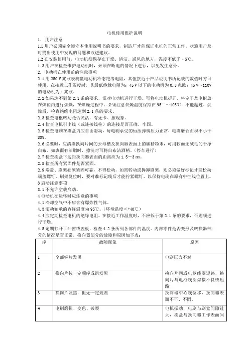
电机使用维护说明1.用户注意1.1用户必须完全遵守本使用说明书的要求,制造厂才能保证电机的正常工作。
欢迎用户及时提出使用中发现的问题和改进建议。
1.2在安装使用前,电动机须保存在干燥、清洁、通风的地方,温度不低于﹣5℃。
1.3用户在检查维护电动机时,必须在断电的情况下进行,以免发生意外。
2.电动机在使用前的注意事项2.1用250 V兆欧表测量电动机冷态绝缘电阻,其值接近于产品说明书所记载的数值时方可使用。
在接近工作温度时,其最低绝缘电阻为:45 V以下的电动机为0.5兆欧;45 V~110V 的电动机为1兆欧。
2.2如果达不到第2.1条的要求,需对电动机进行干燥。
可将电动机拆开,将定子及电枢放在烘箱内进行烘燥,在烘燥过程中,必须注意烘燥温度保持在95°~105℃,不能超过。
烘燥后,检查绝缘电阻达到2.1条的要求。
2.3检查电枢转动是否灵活,有无卡、擦现象。
2.4检查电机引出线(或连接线柱)的连接是否正确、牢固。
2.5检查电刷在刷盒内应自由滑动,每电刷承受的恒压弹簧压力正常,电刷磨合面积不小于80%。
2.6必要时,应清刷换向片间的云母槽及换向器表面上的碳精粉末,可用软而无绒毛的干净白布。
如表面有油脂时,擦洗时可将白布沾酒精。
(停车进行)2.7检查刷盒下边距换向器表面的距离应为1.5-3㎜。
2.8检查所有紧固件是否紧固。
2.9端盖、刷架必须紧固可靠,不得松动。
如需转动或拆卸刷架,则必须做好标记才能松动端盖螺钉。
刷架复位时,要对准标记线后才能拧紧螺钉,以保持电刷在原有中性线位置上。
3启动注意事项3.1不允许空载启动。
4电动机在运转时应注意的事项4.1冷却空气中不应含有爆炸性气体。
4.3滚动轴承的容许温度为95℃。
(环境温度<+40℃)4.4应定期检查电机的绝缘电阻。
在接近工作温度时,不应低于第2.1条的要求,否则须进行干燥。
4.5定期打开百叶窗或盖板,检查4.2条所列各部件的温度。
内部零件是否变形及转换器部如发现异常时,电动机应立即停止工作,在故障清除后,电动机才能恢复工作。
电机产品使用说明书一、概述YT 系列电动机为一般用途三相鼠笼式异步电动机,外壳防护等级IP54,IP55。
冷却方式为IC411。
YT 系列电动机的安装方式符合IEC34-7的规定YT 系列电动机在下列条件下使用:环境空气温度:-15℃≤0≤40℃海拔:不超过1000米额定电压:380V、400V、415V额定频率:50HZ、60HZ接法:3KW及以下规格为Y接法,4KW及以上规格为△接法工作方法:连续(S1)绝缘等级:F,绕组电子温升考核80K防护等级:机壳IP54、IP55,接线盒IP55冷却方式:IC411二、安装前的准备1. 电动机开箱前应检查包装是否完整无损,有无受潮的迹象。
2. 电动机开箱后应小心清除电机上的尘土及防锈层。
3. 检查电动机的铭牌数据是否符合要求。
4. 仔细检查电动机在运输过程中,有无变形或损坏,紧固件有否松动或脱落,试用手转电动机是否灵活。
5. 用500伏兆欧表测量绝缘电阻,其值不应低于0.5兆欧,否则应对定子绕组进行干燥处理,干燥处理时的温度不允许超过120℃。
三、电动机的安装1. 电动机允许用联轴器,正齿轮及皮带轮传动。
双轴伸电动机的风扇端,仅允许用联轴器传动。
2. 采用皮带轮传动时,电动机轴中心线与负载轴中心线平行且要求皮带中心线与轴中心线垂直,采用联轴器传动时,电动机中心线与负中心线应重合。
3. 对立式安装的电动机,轴伸除皮带轮(或相当于普通皮带轮负荷)外不允许再带其他任何轴向负荷装置。
4. 电动机的安装保证其良好的通风冷却条件。
四、电动机的运转1. 电动机应妥善接地,接线盒内有接地装置。
必要时,亦可利用电动机的底脚或法兰盘紧固螺栓接地。
3. 按照铭牌上的接法接成△或Y当电源相序ABC分别与接线柱标志U1、V1、W1相对应时,电动机的转向,从主轴伸端视之为顺时针,更换电源相序,电动机的转向也就与原来的相反。
4. 电动机允许满压起动(用电抗器或Y-△起动器)但应注意,满压起动时有约5-7倍额定电流的起动电流;降压起动时,转矩与电压平方成正比。
电机维修手册摘要:本手册旨在为电机维修人员提供详细的电机维修指南和技巧。
通过了解电机的工作原理和常见故障,本手册将帮助维修人员快速、准确地诊断和解决电机故障,确保电机的正常运行和安全性。
第一章电机基础知识1.1 电机分类- 直流电动机- 交流电动机(异步电动机、同步电动机)1.2 电机工作原理- 电机的构造- 电机的工作原理1.3 电机常见故障- 线圈断路或短路- 电刷磨损- 轴承磨损- 绝缘损坏- 过载或过热第二章电机故障诊断与修复2.1 基本工具和设备- 万用表- 绝缘电阻测试仪- 拆卸工具等2.2 电机故障诊断步骤- 观察电机运行情况- 测量电阻和绝缘电阻- 检查电刷和轴承- 检查线圈和绝缘- 检测过载和过热问题2.3 故障修复与维护- 线圈修复或更换- 电刷更换- 轴承润滑和更换- 绝缘处理和更换- 散热系统维护第三章电机维修案例分析3.1 电机启动困难问题- 可能原因分析- 解决方法和步骤3.2 电机噪音过大问题- 可能原因分析- 解决方法和步骤3.3 电机过热问题- 可能原因分析- 解决方法和步骤第四章电机维护和保养4.1 定期检查和清洁- 清理电机表面和散热器 - 检查接线端子和连接线 - 检查电机固定件- 检查传动装置4.2 润滑和保护- 轴承润滑- 绝缘保护- 电机防尘、防潮处理- 电机通风保护结论:通过掌握本手册所提供的电机维修知识和技巧,电机维修人员将能够有效地诊断和解决电机故障,并进行必要的维护和保养,确保电机的正常运行和延长使用寿命。
电机维修是一项细致繁琐但至关重要的工作,需要专业知识和技能的支持。
希望本手册能够成为电机维修人员的重要参考,并帮助他们更好地完成工作任务。

英格索兰三相异步电机维护保养内容英格索兰三相异步电机是一种常见的电机类型,广泛应用于各个领域。
为了保证电机的正常运行和延长其使用寿命,定期的维护保养是非常必要的。
本文将介绍英格索兰三相异步电机的维护保养内容,以帮助读者更好地了解和操作。
一、定期清洁定期清洁是保养电机的基本措施之一。
由于电机通常运行在恶劣的环境中,如工厂车间、野外等,容易积累灰尘、油脂等杂物。
这些杂物会影响电机的散热和运行效率,甚至导致电机过热而损坏。
因此,定期清洁电机的外壳和散热器是非常重要的。
清洁时,可以使用软刷和吹风机等工具,注意不要碰到电机的绕组和其他易损部件。
二、检查电机温度电机的温度是判断其运行状态的重要指标。
在正常运行情况下,电机温度应该是稳定的,不应过高。
因此,定期测量电机的温度是必要的。
可以使用温度计或红外测温仪等工具进行测量,确保电机温度在允许范围内。
如果发现电机温度异常,应及时检查原因并采取相应措施,以防止电机损坏。
三、检查电机绝缘电机的绝缘状况对其安全运行至关重要。
定期检查电机的绝缘状况是保养的重要内容之一。
可以使用绝缘电阻表等工具进行检测,确保电机的绝缘电阻在合理范围内。
如果发现绝缘电阻过低,可能存在绝缘老化或损坏的情况,需要及时更换绝缘材料或修复绝缘。
四、润滑电机轴承电机轴承是支撑电机转子的重要部件,其润滑状况直接影响电机的运行效率和寿命。
因此,定期对电机轴承进行润滑是必要的。
可以使用适量的润滑油或脂进行润滑,注意不要过量。
润滑时,应先清洁轴承表面的污物,然后均匀地涂抹润滑剂。
另外,还要定期检查轴承的磨损情况,如有需要及时更换。
五、检查电机连接电机的连接状态直接关系到其安全运行和电能转换效率。
因此,定期检查电机的连接是非常重要的。
可以检查电机的接线端子是否松动、焊接是否牢固等。
另外,还可以检查电机的绕组是否存在短路、接地等故障。
如果发现连接异常,应及时进行修复或更换,以确保电机的正常运行。
总结起来,英格索兰三相异步电机的维护保养内容包括定期清洁、检查电机温度、检查电机绝缘、润滑电机轴承和检查电机连接等。
三相异步电动机的使用与维护共37张简介:一、使用1.选型:在选择三相异步电动机时,需要考虑电动机的功率、转速、电源电压等参数,以及实际工作环境和要求。
选型不当会导致电动机无法正常工作或发生故障。
因此,在选型时应根据实际需求进行综合评估。
2.安装:电动机的安装应遵循相关的规范和标准。
首先要选择合适的安装位置,确保电动机固定牢固。
其次,要正确连接电源线路和接地线,避免接触不良或漏电等问题。
3.运行:在电动机正式投入运行前,应对其进行试运行和调试,以确保各个系统和部件的正常工作。
在运行过程中,应监控电动机的运行状态和温度,确保其在安全范围内运行。
4.维护:(1)保持清洁:定期对电动机进行清洁,清除积尘和杂物,保持通风良好。
(2)定期润滑:对电动机的轴承和齿轮等关键部位进行定期润滑,以减少磨损和摩擦。
(3)检查电机绝缘:定期检查电动机的绝缘状态,确保绝缘性能良好,避免漏电和安全事故。
(4)监测振动:定期监测电动机的振动情况,如果振动超出正常范围,应及时进行维修和调整。
(5)检查电流和温度:定期检查电动机的电流和温度,确保其在正常工作范围内,避免过载和过热引起的故障。
二、维护1.常规维护:定期对电动机进行常规维护,包括清洁、润滑、检查电机绝缘等。
这些维护工作可以延长电动机的使用寿命,减少故障和损坏的发生。
2.故障排除:在电动机出现故障时,应及时排除故障。
首先要对故障进行分析和定位,然后采取相应的修复措施。
修复时要注意安全,防止触电和其他事故的发生。
3.定期检修:定期进行全面检修和维护,包括拆卸电动机,更换磨损或老化的部件等。
这样可以及时修复潜在的故障,防止其进一步发展。
4.管理记录:建立电动机的维护台帐,记录维护的时间、方法和结果。
这样可以及时了解电动机的维护情况,发现问题并及时处理。
总结:三相异步电动机的使用和维护非常重要,可以保证其正常工作和延长使用寿命。
在使用时要注意选型、安装和运行。
在维护方面,要进行常规维护、故障排除和定期检修等工作,并建立相应的管理记录。
THREE PHASE INDUCTION MOTORSMAINTENANCE MANUAL
Thank you very much for your kind patronage.Well designed and manufactured, Tatung 3-phase induction motors function excellently and have the longest service life expectance. To provide you , our customers , with necessary technical know-how in examination, operation and maintenance of Tatung motors, we have prepared these instructions. In addition, your attention is also invited to the stipulations on the nameplate of the motor or in other concerned pamphlets.
These instructions only apply to high-and low-voltage squirrel-cage motors of both drip-proof type and totally enclosed fan cooling type, no matter whether they are foot-mounted or flange-mounted. As to motors of special constructions or for special purposes, please refer to their respective attached booklets for information.
Check on receiptInstallation2.1 Installation environment2.2 Foundation and installation
Means of coupling3.1 Centering3.2 Belt transmission
Running4.1 Check before starting4.2 Starting
Maintenance5.1 Knock-down examination5.2 Recording
Bearing maintenance6.1 Tip for maintenance6.2 Construction, classification and application of bearings6.3 Starting the motors for running after stopping running for more than 2 months6.4 Grease Supply6.5 Removal of grease6.6 Problems of poor lubrication6.7 Bearing diagnosis6.8 Makers or brands for grease6.9 Tips for assembling and disassembling6.10 Sealed ball bearing
VibrationNoise8.
7.
6.5.4.3.2.1.1.Check on receiptPlease check the following items on receipt.Read carefully the testing records.Check and see whether the motors are damaged or dirtied;and make sure there is no part or accessory missing and no foreign body in the motors.
Run the motor and make sure the direction of rotation agrees with that indicated, if there is such an indication . The direction is always indicated by an arrow plate attached on the motor.
Read carefully the ratings on the main nameplate and other plates or attached pamphlets.
Rotate the shaft manually and make sure it rotates normally. (To prevent against axial movement of rotors and damages to roller bearings, the shafts of motors of 2 poles and motors with roller bearings are locked during transport. Please unlock them before rotating .)
If there are some special requirements, such as, certain particular color, paint, and accessories, please check to see whether they are satisfied.
In case there is any problem or discrepancy found , please contact Tatung Company or its service station nearest to you , and give us the following in-formation: The type, poles,output capacity, voltage and frequency shown on the nameplate; also the test number and manufacture number (they are either marked on nameplate or on the endface of shaft).
If you are a machine manufacturer , Please pay your attention to the following :In case the rotors of Tatung motors you received have been locked for above-stated purpose, you are required to lock the rotors again, either by the
F.E.D.C.B.A.means described above or by the means shown below:2.Installation2.1 Installation environment Since well selected environment contributes very much to proper functioning of motors , you , therefore , must give your careful consideration to this matter when you prepare your purchase specifications . However , to insure operational safety , the following items are listed for your information :
Environment temperatureFor standard motors , environment temperature normally has to be within the range from -15℃ to 40℃.
In case the environment temperature is too high , or excessive heat is inflected on the motor , protective measures , such as cooling measures or heat-insulating measures , should be taken ; or the load which makes the motor over-heated reduced .
On the contrary , if the environment temperature is too low , heating measures will also be necessary .
In case the motor is operated in the environment where the temperature falls out of the range as stated above , either too low or too high , design-wise re-consideration over the insulation , lead wire , lubrication , bearings fittings , steel parts and weldings of the motor is deemed necessary .
Good ventilationIf the circulation of cooling air into the motor is broken or impeded , abnormal temperature rising will occur.
Please keep things at least 20cm off INTAKE AIR ports .Poorly ventilated environmentIf the motor is installed in poorly ventilated environment, improvement steps have to be taken to guard the motor against being overheated .