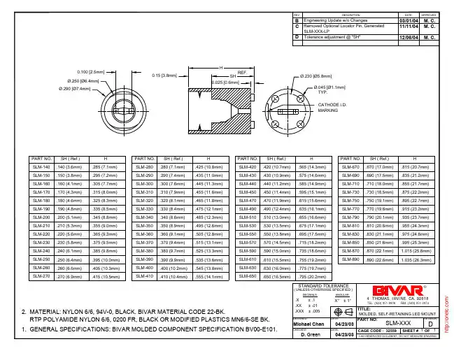
150D336X0010B2中文资料
- 格式:pdf
- 大小:77.09 KB
- 文档页数:9
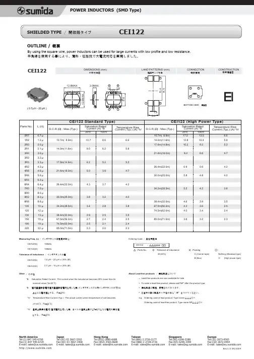
OUTLINE /CEI1221.2µH – 22µH ± 20% (M)0.7µH – 15µH ± 20% (M)/ その他Other *IV Temperature Rise Current (Typ.) : The actual current when temperature of coil becomes∆T=40°C. (Ta=20*IV温度上昇実力電流:直流電流を流した時、コイルの温度上昇がΔT=40℃となる電流の実力値°C)°C)nominal value.(Ta=20 とする。
(Ta=20℃)*B 直流重畳許容電流:直流重畳許容電流を流した時、インダクタンスが公称インダクタンスの75%以*B Saturation Rated Current : The current when the inductance becomes 25% lower than its上となる電流値とする。
(Ta=20℃)( 0.7µH - 22µH )概要By using the square wire, power inductors can be used for large currents with low profile and low resistance.平角線を使用する事により、薄形・低抵抗で大電流対応を実現しました。
/ インダクタンス公差/ インダクタンス測定周波数(L)100kHz 100kHzMeasuring Freq. (L)Tolerance of Inductance CEI122(S)CEI122(H)CEI122(S)/ 無鉛製品についてAbout Lead-free products .Lead-free products are now available for sale.To order a lead-free product, please add"NP" after the product type:無鉛製品は現在、販売されております。
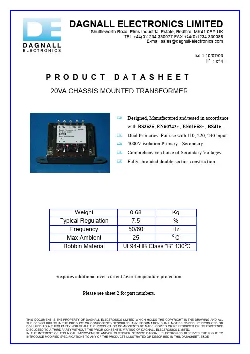
E-mail sales@ THIS DOCUMENT IS THE PROPERTY OF DAGNALL ELECTRONICS LIMITED WHICH HOLDS THE COPYRIGHT IN THE DRAWING AND ALLIss 1 10/07/031 of 4P R O D U C T D A T A S H E E T20VA CHASSIS MOUNTED TRANSFORMERWeight 0.68Kg Typical Regulation 7.5 %Frequency 50/60 HzMax Ambient 25 o CBobbin Material UL94-HB Class “B” 130o C∗requires additional over-current /over-temperature protection.Please see sheet 2 for part numbers.THE DESIGN RIGHTS IN THE PRODUCT OR COMPONENTS DESCRIBED. ANY INFORMATION SHALL NOT BE COPIED, REPRODUCED OR DIVULGED TO A THIRD PARTY NOR SHALL THE PRODUCT OR COMPONENTS BE MADE, COPIED OR REPRODUCED OR ITS EXISTENCE DISCLOSED TO A THIRD PARTY WITHOUT THE PRIOR CONSENT IN WRITING OF DAGNALL ELECTRONICS LIMITED.D esigned, Manufactured and tested in accordancewith BS3535, EN60742∗ , EN61558∗ , BS415.D ual Primaries. For use with 110, 220, 240 input4000V isolation Primary - SecondaryComprehensive choice of Secondary Voltages.Fully shrouded double section construction.E-mail sales@THIS DOCUMENT IS THE PROPERTY OF DAGNALL ELECTRONICS LIMITED WHICH HOLDS THE COPYRIGHT IN THE DRAWING AND ALL THE DESIGN RIGHTS IN THE PRODUCT OR COMPONENTS DESCRIBED. ANY INFORMATION SHALL NOT BE COPIED, REPRODUCED OR DIVULGED TO A THIRD PARTY NOR SHALL THE PRODUCT OR COMPONENTS BE MADE, COPIED OR REPRODUCED OR ITS EXISTENCE DISCLOSED TO A THIRD PARTY WITHOUT THE PRIOR CONSENT IN WRITING OF DAGNALL ELECTRONICS LIMITED.Iss 1 10/07/032 of 4Part NumbersPart No Primary SecondaryRecommendedSecondary FuseD3647 0-110 0-110-130V 4.5+4.5V 2AT D3648 0-110 0-110-130V 6+6V 1.6AT D3649 0-110 0-110-130V 9+9V 1AT D3650 0-110 0-110-130V 10V 2AT D3651 0-110 0-110-130V 12+12V 0.8AT D3652 0-110 0-110-130V 15+15V0.63AT D3653 0-110 0-110-130V 18+18V0.5AT D3654 0-110 0-110-130V 20+20V0.5AT D3655 0-110 0-110-130V 24+24V0.4ATPlease see sheets 3 and 4 for dimensions, pin outs and connection information.。
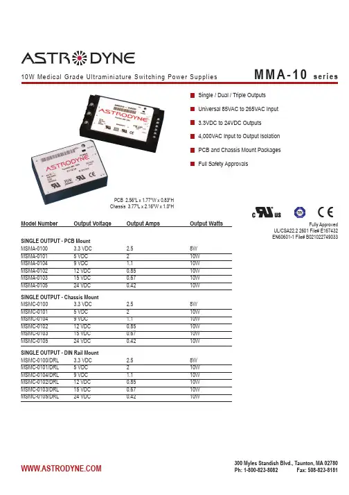
Model Number Output VoltageOutput Amps Output WattsSINGLE OUTPUT - PCB MountMSMA-0100 3.3 VDC 2.5 8W MSMA-0101 5 VDC 2 10W MSMA-0104 9 VDC 1.1 10W MSMA-0102 12 VDC 0.85 10W MSMA-0103 15 VDC 0.67 10W MSMA-0105 24 VDC 0.42 10W SINGLE OUTPUT - Chassis Mount MSMC-0100 3.3 VDC 2.5 8W MSMC-0101 5 VDC 2 10W MSMC-0104 9 VDC 1.1 10W MSMC-0102 12 VDC 0.85 10W MSMC-0103 15 VDC 0.67 10W MSMC-0105 24 VDC 0.42 10W SINGLE OUTPUT - DIN Rail Mount MSMC-0100/DRL 3.3 VDC 2.5 8W MSMC-0101/DRL 5 VDC 2 10W MSMC-0104/DRL 9 VDC 1.1 10W MSMC-0102/DRL 12 VDC 0.85 10W MSMC-0103/DRL 15 VDC 0.67 10W MSMC-0105/DRL 24 VDC0.4210WSingle / Dual / Triple Outputs Universal 85VAC to 265VAC Input 3.3VDC to 24VDC Outputs 4,000VAC Input to Output Isolation PCB and Chassis Mount Packages Full Safety ApprovalsPCB 2.56”L x 1.77”W x 0.83”HChassis 3.77”L x 2.16”W x 1.0”HFully ApprovedUL/CSA22.2 2601 File# E167432EN60601-1 File# B021*********Model Number Output Voltage Output Amps Output WattsDUAL OUTPUT - PCB Mount MDMA-0106 +/-12 VDC +/-0.42 10W MDMA-0107 +/-15 VDC +/-0.34 10W MDMA-0108 +5/12 VDC 1/0.42 10W DUAL OUTPUT - Chassis Mount MDMC-0106 +/-12 VDC +/-0.42 10W MDMC-0107 +/-15 VDC +/-0.34 10W MDMC-0108 +5/12 VDC 1/0.42 10W DUAL OUTPUT - DIN Rail Mount MDMC-0106/DRL +/-12 VDC +/-0.42 10W MDMC-0107/DRL +/-15 VDC +/-0.34 10W MDMC-0108/DRL +5/12 VDC 1/0.42 10W TRIPLE OUTPUT - PCB Mount MTMA-0109 +5,+/-12 VDC 1.5,0.1/0.1 10W MTMA-0111 +5,+/-15 VDC 1.4,0.1/0.1 10W TRIPLE OUTPUT - Chassis Mount MTMC-0109 +5,+/-12 VDC 1.5,0.1/0.1 10W MTMC-0111 +5,+/-15 VDC 1.4,0.1/0.1 10W TRIPLE OUTPUT - DIN Rail Mount MTMC-0109/DRL +5,+/-12 VDC 1.5,0.1/0.1 10W MTMC-0111/DRL +5,+/-15 VDC1.4,0.1/0.110WSingle / Dual / Triple Outputs Universal 85VAC to 265VAC Input 3.3VDC to 24VDC Outputs 4,000VAC Input to Output Isolation PCB and Chassis Mount Packages Full Safety ApprovalsPCB 2.56”L x 1.77”W x 0.83”HChassis 3.77”L x 2.16”W x 1.0”HFully ApprovedUL/CSA22.2 2601 File# E167432EN60601-1 File# B021********** These are stress ratings. Exposure of the devices to any of these conditionsmay adversely affect long term reliability. Proper operation under conditions other than the standard operating conditions is neither warranteed nor implied.All specifications are typical at nominal input, full load, and 25DegC unless otherwise notedAstrodyne products are not authorized or warranteed for use as critical components in life support systems, equipment used in hazardous environments, nuclear controls systems, or other mission-critical applications.INPUT SPECIFICATIONSInput Voltage, Nominal 85-265VACNominal: 100-240VAC Input Frequency 47-440 Hz, 50-60Hz Nom. Inrush Current 20A @ 100VAC, typ40A @ 200VAC, typOUTPUT SPECIFICATIONSOutput Voltage/Current See Specific Model Initial Accuracy +/-1%, adjustable Voltage Adjust +/-6%, typ Load Regulation +/-0.3%, typ Line Regulation+/-0.3%, typ Temperature Coefficient +/-0.03%/°CRipple/Noise(20Mhz BW) 150mV Pk-Pk, typ Overvoltage Protection Clamp, 130-150% * Hold Up Time30mS, typShort Circuit Protection Continuous, self-recovering * Current Limit130% typ,Self-Reset FoldbackGENERAL SPECIFICATIONSOn/Off Control Open Collector Logic “1”/Open=ONLogic “0”/GND=OFF Input-Out Isolation4000VAC Output-Ground Isolation 1000VAC Input-Ground Isolation 2500VAC Operating Frequency 140 Khz, fixed Efficiency (@ Full Load)75 - 80%, typENVIRONMENTAL SPECIFICATIONSOper. Temperature 0 to +50°C FL See Derate *(Free-air Convection) Relative Humidity 0-95%, Non-Condensing Storage Temperature -25 to +71°C *MTBF, Single/Multi Output 180,000 Hrs/110,000 HrsMil Std 217, 25°CPHYSICAL SPECIFICATIONSCase Material Rynite, 94V-0 RatedConstruction Encapsulated, Soft Pot Weight PCB / CHA4.6 oz (128g) / 8.5 oz (238g)MECHANICAL DIMENSIONS - PCB MOUNTModel Dual Dual Type / Pin# Single Matched 5/12V Triple 1 AC HI AC HI AC HI AC HI 2 AC LO AC LO AC LO AC LO 3 GND GND GND GND 4 No Pin No Pin No Pin +Vout 5No Pin No Pin No Pin +/-Com 6 +Vout +Vout 12Vout No Pin 7 No Pin No Pin No Pin -Vout 8No Pin Out Com +5Vout +5Vout 9 -Vout -Vout Out Com 5V Ret10CtrlCtrlCtrlCtrlPERFORMANCE CURVES100907050403020108060010203040506070-10O u t p u t C u r r e n t , %Ambient Temp., DegC90605080704025507510010T y p i c a l E f f i c i e n cy , %% of Full LoadMECHANICAL DIMENSIONS - CHASSIS MOUNT.(2 PLACES)0.100 [2.54]Model Match Unmatch TripleType / Pin#Single DualDual1 AC LO AC LO AC LO AC LO2 GND GND GND GND3 AC HI AC HI AC HI AC HI4 Ctrl Ctrl Ctrl Ctrl5 -Vout -Vout Com +5 Ret6 -Vout Com Com +5Vout7 +Vout Com +5Vout -Vout8 +Vout +Vout +12Vout +/- Com 9N/CN/CN/C+VoutDIN Rail mounting kit available for Chassis-mount modules, specify part # M-DRL-01. Kit includes mounting plate, DIN Rail cliip and assembly hardware.MECHANICAL DIMENSIONS - DIN RAIL。
PACKAGING INFORMATIONOrderable Device Status(1)PackageType PackageDrawingPins PackageQtyEco Plan(2)Lead/Ball Finish MSL Peak Temp(3)SN65176BD ACTIVE SOIC D875Green(RoHS&no Sb/Br)CU NIPDAU Level-1-260C-UNLIMSN65176BDE4ACTIVE SOIC D875Green(RoHS&no Sb/Br)CU NIPDAU Level-1-260C-UNLIMSN65176BDG4ACTIVE SOIC D875Green(RoHS&no Sb/Br)CU NIPDAU Level-1-260C-UNLIMSN65176BDR ACTIVE SOIC D82500Green(RoHS&no Sb/Br)CU NIPDAU Level-1-260C-UNLIMSN65176BDRE4ACTIVE SOIC D82500Green(RoHS&no Sb/Br)CU NIPDAU Level-1-260C-UNLIMSN65176BDRG4ACTIVE SOIC D82500Green(RoHS&no Sb/Br)CU NIPDAU Level-1-260C-UNLIMSN65176BP ACTIVE PDIP P850Pb-Free(RoHS)CU NIPDAU N/A for Pkg TypeSN65176BPE4ACTIVE PDIP P850Pb-Free(RoHS)CU NIPDAU N/A for Pkg TypeSN75176BD ACTIVE SOIC D875Green(RoHS&no Sb/Br)CU NIPDAU Level-1-260C-UNLIMSN75176BDE4ACTIVE SOIC D875Green(RoHS&no Sb/Br)CU NIPDAU Level-1-260C-UNLIMSN75176BDG4ACTIVE SOIC D875Green(RoHS&no Sb/Br)CU NIPDAU Level-1-260C-UNLIMSN75176BDR ACTIVE SOIC D82500Green(RoHS&no Sb/Br)CU NIPDAU Level-1-260C-UNLIMSN75176BDRE4ACTIVE SOIC D82500Green(RoHS&no Sb/Br)CU NIPDAU Level-1-260C-UNLIMSN75176BDRG4ACTIVE SOIC D82500Green(RoHS&no Sb/Br)CU NIPDAU Level-1-260C-UNLIMSN75176BP ACTIVE PDIP P850Pb-Free(RoHS)CU NIPDAU N/A for Pkg TypeSN75176BPE4ACTIVE PDIP P850Pb-Free(RoHS)CU NIPDAU N/A for Pkg TypeSN75176BPSR ACTIVE SO PS82000Green(RoHS&no Sb/Br)CU NIPDAU Level-1-260C-UNLIMSN75176BPSRG4ACTIVE SO PS82000Green(RoHS&no Sb/Br)CU NIPDAU Level-1-260C-UNLIM(1)The marketing status values are defined as follows:ACTIVE:Product device recommended for new designs.LIFEBUY:TI has announced that the device will be discontinued,and a lifetime-buy period is in effect.NRND:Not recommended for new designs.Device is in production to support existing customers,but TI does not recommend using this part in a new design.PREVIEW:Device has been announced but is not in production.Samples may or may not be available.OBSOLETE:TI has discontinued the production of the device.(2)Eco Plan-The planned eco-friendly classification:Pb-Free(RoHS),Pb-Free(RoHS Exempt),or Green(RoHS&no Sb/Br)-please check /productcontent for the latest availability information and additional product content details.TBD:The Pb-Free/Green conversion plan has not been defined.Pb-Free(RoHS):TI's terms"Lead-Free"or"Pb-Free"mean semiconductor products that are compatible with the current RoHS requirements for all6substances,including the requirement that lead not exceed0.1%by weight in homogeneous materials.Where designed to be soldered at high temperatures,TI Pb-Free products are suitable for use in specified lead-free processes.Pb-Free(RoHS Exempt):This component has a RoHS exemption for either1)lead-based flip-chip solder bumps used between the die andpackage,or2)lead-based die adhesive used between the die and leadframe.The component is otherwise considered Pb-Free(RoHS compatible)as defined above.Green(RoHS&no Sb/Br):TI defines"Green"to mean Pb-Free(RoHS compatible),and free of Bromine(Br)and Antimony(Sb)based flame retardants(Br or Sb do not exceed0.1%by weight in homogeneous material)(3)MSL,Peak Temp.--The Moisture Sensitivity Level rating according to the JEDEC industry standard classifications,and peak solder temperature.Important Information and Disclaimer:The information provided on this page represents TI's knowledge and belief as of the date that it is provided.TI bases its knowledge and belief on information provided by third parties,and makes no representation or warranty as to the accuracy of such information.Efforts are underway to better integrate information from third parties.TI has taken and continues to take reasonable steps to provide representative and accurate information but may not have conducted destructive testing or chemical analysis on incoming materials and chemicals.TI and TI suppliers consider certain information to be proprietary,and thus CAS numbers and other limited information may not be available for release.In no event shall TI's liability arising out of such information exceed the total purchase price of the TI part(s)at issue in this document sold by TI to Customer on an annual basis.TAPE AND REEL INFORMATIONDevice Package Pins Site ReelDiameter(mm)ReelWidth(mm)A0(mm)B0(mm)K0(mm)P1(mm)W(mm)Pin1QuadrantSN65176BDR D8FMX33012 6.4 5.2 2.1812Q1 SN75176BDR D8FMX33012 6.4 5.2 2.1812Q1 SN75176BPSR PS8MLA330168.2 6.6 2.51216Q1TAPE AND REEL BOX INFORMATIONDevice Package Pins Site Length(mm)Width(mm)Height(mm)SN65176BDR D8FMX338.1340.520.64SN75176BDR D8FMX338.1340.520.64SN75176BPSR PS8MLA342.9336.628.58IMPORTANT NOTICETexas Instruments Incorporated and its subsidiaries (TI)reserve the right to make corrections,modifications,enhancements,improvements,and other changes to its products and services at any time and to discontinue any product or service without notice.Customers should obtain the latest relevant information before placing orders and should verify that such information is current and complete.All products are sold subject to TI’s terms and conditions of sale supplied at the time of order acknowledgment.TI warrants performance of its hardware products to the specifications applicable at the time of sale in accordance with TI’s standard warranty.Testing and other quality control techniques are used to the extent TI deems necessary to support this warranty.Except where mandated by government requirements,testing of all parameters of each product is not necessarily performed.TI assumes no liability for applications assistance or customer product design.Customers are responsible for their products and applications using TI components.To minimize the risks associated with customer products and applications,customers should provide adequate design and operating safeguards.TI does not warrant or represent that any license,either express or implied,is granted under any TI patent right,copyright,mask work right,or other TI intellectual property right relating to any combination,machine,or process in which TI products or services are rmation published by TI regarding third-party products or services does not constitute a license from TI to use such products or services or a warranty or endorsement e of such information may require a license from a third party under the patents or other intellectual property of the third party,or a license from TI under the patents or other intellectual property of TI.Reproduction of information in TI data books or data sheets is permissible only if reproduction is without alteration and isaccompanied by all associated warranties,conditions,limitations,and notices.Reproduction of this information with alteration is an unfair and deceptive business practice.TI is not responsible or liable for such altered documentation.Resale of TI products or services with statements different from or beyond the parameters stated by TI for that product or service voids all express and any implied warranties for the associated TI product or service and is an unfair and deceptive business practice.TI is not responsible or liable for any such statements.TI products are not authorized for use in safety-critical applications (such as life support)where a failure of the TI product would reasonably be expected to cause severe personal injury or death,unless officers of the parties have executed an agreementspecifically governing such use.Buyers represent that they have all necessary expertise in the safety and regulatory ramifications of their applications,and acknowledge and agree that they are solely responsible for all legal,regulatory and safety-related requirements concerning their products and any use of TI products in such safety-critical applications,notwithstanding any applications-related information or support that may be provided by TI.Further,Buyers must fully indemnify TI and itsrepresentatives against any damages arising out of the use of TI products in such safety-critical applications.TI products are neither designed nor intended for use in military/aerospace applications or environments unless the TI products are specifically designated by TI as military-grade or "enhanced plastic."Only products designated by TI as military-grade meet military specifications.Buyers acknowledge and agree that any such use of TI products which TI has not designated as military-grade is solely at the Buyer's risk,and that they are solely responsible for compliance with all legal and regulatory requirements in connection with such use.TI products are neither designed nor intended for use in automotive applications or environments unless the specific TI products are designated by TI as compliant with ISO/TS 16949requirements.Buyers acknowledge and agree that,if they use any non-designated products in automotive applications,TI will not be responsible for any failure to meet such requirements.Following are URLs where you can obtain information on other Texas Instruments products and application solutions:ProductsApplications AmplifiersAudioDataConvertersAutomotiveDSPBroadband InterfaceDigital Control LogicMilitary Power MgmtOptical Networking MicrocontrollersSecurity RFIDTelephony Low PowerVideo &ImagingWireless Wireless Mailing Address:Texas Instruments,Post Office Box 655303,Dallas,Texas 75265Copyright ©2007,Texas Instruments Incorporated 元器件交易网。
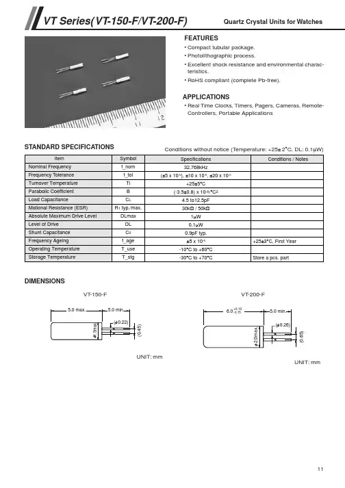
11VT Series(VT-150-F/VT-200-F)Quartz Crystal Units for Watches
FEATURES•Compact tubular package.•Photolithographic process.•Excellent shock resistance and environmental charac-teristics.
•RoHS compliant (complete Pb-free).
APPLICATIONS•Real Time Clocks, Timers, Pagers, Cameras, Remote-Controllers, Portable Applications
STANDARD SPECIFICATIONS
DIMENSIONS ItemNominal FrequencyFrequency ToleranceTurnover TemperatureParabolic CoefficientLoad CapacitanceMotional Resistance (ESR)Absolute Maximum Drive LevelLevel of DriveShunt CapacitanceFrequency AgeingOperating TemperatureStorage Temperature
Specifications32.768kHz(±5 x 10⁻⁶), ±10 x 10-6, ±20 x 10-6
+25±5°C(-3.5±0.8) x 10-8/°C24.5 to 12.5pF30kΩ / 50kΩ1µW0.1µW0.9pF typ.±5 x 10⁻⁶
-10°C to +60°C-30°C to +70°C
Conditions / Notes+25±3°C, First YearSymbol
f_nomf_tolTiBCL
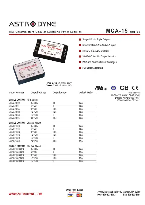
Model Number Output VoltageOutput Amps Output WattsSINGLE OUTPUT - PCB MountMSCA-1500 3.3 VDC 3.512W MSCA-1501 5 VDC 3 15W MSCA-1504 9 VDC 1.66 15W MSCA-1502 12 VDC 1.25 15W MSCA-1503 15 VDC 1 15W MSCA-1505 24 VDC 0.63 15W SINGLE OUTPUT - Chassis Mount MSCC-1500 3.3 VDC 3.5 12W MSCC-1501 5 VDC 3 15W MSCC-1504 9 VDC 1.66 15W MSCC-1502 12 VDC 1.25 15W MSCC-1503 15 VDC 1 15W MSCC-1505 24 VDC 0.63 15W SINGLE OUTPUT - DIN Rail Mount MSCC-1500/DRL 3.3 VDC 3.5 12W MSCC-1501/DRL 5 VDC 3 15W MSCC-1504/DRL 9 VDC 1.66 15W MSCC-1502/DRL 12 VDC 1.25 15W MSCC-1503/DRL 15 VDC115WPCB 2.75”L x 1.89”W x 0.93”H Chassis 3.96”L x 2.16”W x 1.0”HSingle / Dual / Triple Outputs Universal 85VAC to 265VAC Input 3.3VDC to 24VDC Outputs 3,000VAC Input to Output Isolation PCB and Chassis Mount Packages Full Safety ApprovalsFully ApprovedUL/CSA22.2 60950-1 File# E167432EN60950 File# B021*********IEC60950-1 File# DE354012Model Number Output Voltage Output Amps Output WattsDUAL OUTPUT - PCB Mount MDCA-1506 +/-12 VDC +/-0.6315W MDCA-1507 +/-15 VDC +/-0.5 15W MDCA-1508 +5/12 VDC 1.5/0.63 15W DUAL OUTPUT - Chassis Mount MDCC-1506 +/-12 VDC +/-0.63 15W MDCC-1507 +/-15 VDC +/-0.5 15W MDCC-1508 +5/12 VDC 1.5/0.63 15W DUAL OUTPUT - DIN Rail Mount MDCC-1506/DRL +/-12 VDC +/-0.63 15W MDCC-1507/DRL +/-15 VDC +/-0.5 15W MDCC-1508/DRL +5/12 VDC 1.5/0.63 15W TRIPLE OUTPUT - PCB Mount MTCA-1509 +5,+/-12 VDC 2.5,0.1/0.1 15W MTCA-1511 +5,+/-15 VDC 2.5,0.1/0.1 15W TRIPLE OUTPUT - Chassis Mount MTCC-1509 +5,+/-12 VDC 2.5,0.1/0.1 15W MTCC-1511 +5,+/-15 VDC 2.5,0.1/0.1 15W TRIPLE OUTPUT - DIN Rail Mount MTCC-1509/DRL +5,+/-12 VDC 2.5,0.1/0.1 15W MTCC-1511/DRL +5,+/-15 VDC2.5,0.1/0.115WPCB 2.75”L x 1.89”W x 0.93”H Chassis 3.96”L x 2.16”W x 1.0”HSingle / Dual / Triple Outputs Universal 85VAC to 265VAC Input 3.3VDC to 24VDC Outputs 3,000VAC Input to Output Isolation PCB and Chassis Mount Packages Full Safety ApprovalsFully ApprovedUL/CSA22.2 60950-1 File# E167432EN60950 File# B021*********IEC60950-1 File# DE354012* These are stress ratings. Exposure of the devices to any of these conditionsmay adversely affect long term reliability. Proper operation under conditions other than the standard operating conditions is neither warranteed nor implied.All specifications are typical at nominal input, full load, and 25DegC unless otherwise notedAstrodyne products are not authorized or warranteed for use as critical components in life support systems, equipment used in hazardous environments, nuclear controls systems, or other mission-critical applications.INPUT SPECIFICATIONSInput Voltage, Nominal 85-265VACNominal: 100-240VAC Input Frequency 47-440 Hz, 50-60Hz Nom. Inrush Current 20A @ 100VAC, typ40A @ 200VAC, typOUTPUT SPECIFICATIONSOutput Voltage/Current See Specific Model Initial Accuracy +/-1%, adjustable Voltage Adjust +/-6%, typ Load Regulation +/-0.3%, typ Line Regulation+/-0.3%, typ Temperature Coefficient +/-0.03%/°CRipple/Noise(20Mhz BW) 150mV Pk-Pk, typ Overvoltage Protection Clamp, 130-150% * Hold Up Time30mS, typShort Circuit Protection Continuous, self-recovering * Current Limit130% typ,Self-Reset FoldbackGENERAL SPECIFICATIONSOn/Off Control Open Collector Logic “1”/Open=ONLogic “0”/GND=OFF Input-Out Isolation3000VAC Output-Ground Isolation 1000VAC Input-Ground Isolation 2500VAC Operating Frequency 140 Khz, fixed Efficiency (@ Full Load)75 - 80%, typENVIRONMENTAL SPECIFICATIONSOper. Temperature 0 to +50°C FL See Derate *(Free-air Convection) Relative Humidity 0-95%, Non-Condensing Storage Temperature -25 to +71°C *MTBF, Single/Multi Output 180,000 Hrs/110,000 HrsMil Std 217, 25CPHYSICAL SPECIFICATIONSCase Material Rynite, 94V-0 RatedConstruction Encapsulated, Soft Pot Weight PCB / CHA5.6 oz (158g) / 8.9 oz (250g)MECHANICAL DIMENSIONS - PCB MOUNTModel Dual Dual Type / Pin# Single Matched 5/12V Triple 1 AC HI AC HI AC HI AC HI 2 AC LO AC LO AC LO AC LO 3 GND GND GND GND 4 No Pin No Pin No Pin +Vout 5+Vout +Vout 12Vout +/-Com 6 No Pin No Pin No Pin -Vout 7 No Pin Out Com +5Vout +5Vout 8-Vout -Vout Out Com +5V Ret9CtrlCtrlCtrlCtrlPERFORMANCE CURVES100907050403020108060010203040506070-10O u t p u t C u r r e n t , %Ambient Temp., DegC90605080704025507510010T y p i c a l E f f i c i e n c y , %% of Full Load0.100 [2.54]MECHANICAL DIMENSIONS - DIN RAILModel Match Unmatch TripleType / Pin#Single DualDual1 AC LO AC LO AC LO AC LO2 GND GND GND GND3 AC HI AC HI AC HI AC HI4 Ctrl Ctrl Ctrl Ctrl5 -Vout -Vout Com +5 Ret6 -Vout Com Com +5Vout7 +Vout Com +5Vout -Vout8 +Vout +Vout +12Vout +/- Com 9N/CN/CN/C+VoutMECHANICAL DIMENSIONS - CHASSIS MOUNT987654123DIN Rail mounting kit available for Chassis-mount modules, specify part # M-DRL-15. Kit includes mounting plate, DIN Rail cliip and assembly hardware.。
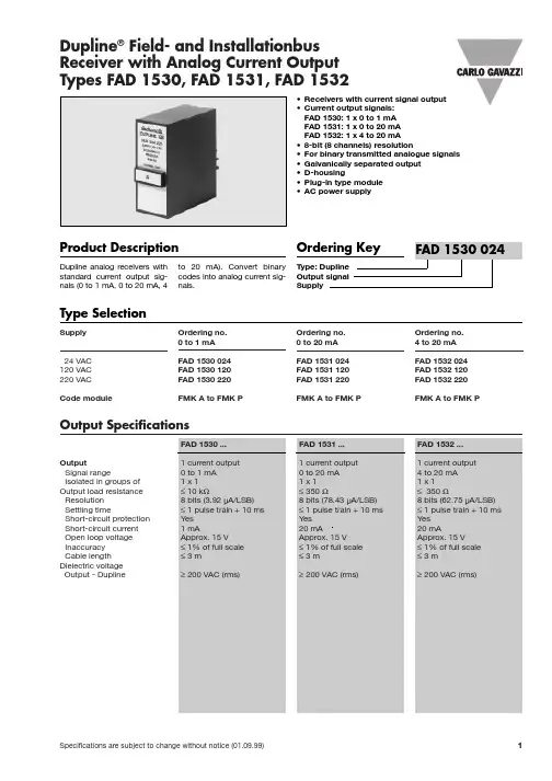
Specifications are subject to change without notice (01.09.99)1Dupline®Field- and InstallationbusType: DuplineOutput signalSupply
Ordering Key
•Receivers with current signal output•Current output signals:FAD 1530: 1 x 0 to 1 mAFAD 1531: 1 x 0 to 20 mAFAD 1532: 1 x 4 to 20 mA•8-bit (8 channels) resolution•For binary transmitted analogue signals•Galvanically separated output•D-housing•Plug-in type module•AC power supply
Product DescriptionDupline analog receivers withstandard current output sig-nals (0 to 1 mA, 0 to 20 mA, 4to 20 mA). Convert binarycodes into analog current sig-nals.
Type SelectionSupplyOrdering no.Ordering no.Ordering no.0 to 1 mA0 to 20 mA4 to 20 mA
24 VACFAD 1530 024FAD 1531 024FAD 1532 024120 VACFAD 1530 120FAD 1531 120FAD 1532 120220 VAC FAD 1530 220FAD 1531 220FAD 1532 220
Code moduleFMK A to FMK PFMK A to FMK PFMK A to FMK P
&HUDPLF 5HVRQDWRUV &KLS 7\SH %XLOW ,Q &DSDFLWRUV 7\SH7\SH 6 WR 0+] 7\SH % WR 0+] 7\SH 7 WR 0+] 7\SH- WR 0+]I Explanation of Part NumbersI FeaturesG (QFDVHG LQ FHUDPLF SDFNDJHG +LJK UHOLDELOLW\ DJDLQVW VROGHULQJ KHDW DQG PHFKDQLFDO VWUHVVG 0RLVWXUH SURRI VHDOLQJG /RZ 3URILOH 7\SH PP PD[LPXP LQ WKLFNQHVV G 'HVLJQHG IRU UHIORZ VROGHULQJG )ODW ERWWRP SODWH IRU EHWWHU PRXQWLQJVG &RQWULEXWHV to s LPSOLILFDWLRQ RI RVFLOODWLRQ FLUFXLWV DQG UHGXFHV WKH QXPEHUV RI FLUFXLW SDUWVI Recommended ApplicationsG &ORFN JHQHUDWRU IRU PLFURSURFHVVHUVG &DUULHU EHWZHHQ WHOHFRPPXQLFDWLRQ HTXLSPHQW 7HOHSKRQH WR WHOHSKRQH SHUVRQDO FRPSXWHU WR SULQWHUI Safety Precautions3DUW 1XPEHU2VFLOODWLRQ )UHTXHQF\/RRS *DLQ7HPSHUDWXUH %XON 3DFN (PERVVHG 7DSLQJ IR * &KDUDFWHULVWLFV EFOS3584B5EFOS3584E5 0+] 0D[LPXP IUHTXHQF\ GULIW EFOS4004B5EFOS4004E5 0+] G% PLQ¤ WR &EFOS8004B5EFOS8004E5 0+] EFOS1005B5EFOS1005E5 0+] G% PLQ0D[LPXP IUHTXHQF\ GULIW EFOS1205B5EFOS1205E5 0+] ¤ WR &EFOB1605B5EFOB1605E5 0+] 0D[LPXP IUHTXHQF\ GULIW EFOB1695B5EFOB1695E5 0+] G% PLQ¤ WR &EFOB2005B5EFOB2005E5 0+] EFOT2405B5EFOT2405E5 0+] EFOT2545B5EFOT2545E5 0+] G% PLQ0D[LPXP IUHTXHQF\ GULIW EFOJ3205B5EFOJ3205E5 0+] ¤ WR &EFOJ3385B5EFOJ3385E5 0+] G% PLQEFOJ4005B5EFOJ4005E50+]I Ratings and Characteristics1RWH$OVR DYDLODEOH DUH W\SHV RWKHU WKDQ DERYH VWDQGDUG SURGXFWV LQ WKH IUHTXHQF\ UDQJH RI WR 0+]3OHDVH FRQWDFW XV IRU PRUH LQIRUPDWLRQG 2SHUDWLQJ 7HPSHUDWXUH 5DQJH ¤ WR Í&I Dimensions in mm (not to scale)EFOS E[Type B] EFOB BEFOB E'LP 3 3 I ' W W I &I ' PPPD[ PD['LP $%:)(3PP'LP 3 3 I ' W WPPPD[ PD['LP $%:)(3PP[Type T] EFOT BEFOT E'LP 3 3 I ' W WPPPD[ PD['LP $%:)(3PPEFOJ E'LP 3 3 I ' W WPPPD[ PD['LP $%:)(3PPI Test Circuits Diagram)UHTXHQF\,&WR 0+] 3' 8%&WR 0+] 3' +&87\SH 67\SH %7\SH 77\SH -DE WR WRF WR WRG¥¥¥ WR I Typical Characteristics I Recommended Land DimensionsI Packaging Specifications6XSSOLHG LQ EXON RU WDSHG UHHO SDFNLQJ VW\OHG Standard Packing Quantity7\SH(PERVVHG 7DSLQJ%XON6 SFV UHHO SFV EDJ% 7 - SFV UHHO SFV EDJG'LP I$I%&'(PP PLQ'LP :7W UPP PD[ PD[Temperature Characteristics(Type S,B,T,J)PP[Type S]'LP I$I%&'(PP PLQ'LP :7W UPP PD[ PD[[Type B,T,J]。
2.8.020配件及类似件二级供货规范1—目的2—缩写3—应用4—定义5—参考6—职责7—标准7.1—规则要求7.1.1—配件类型7.1.2—配件管理7.1.3—资料管理7.1.4—证书要求7.1.5—图纸说明7.1.6—碱性材料7.2—配件等级7.3—制造7.3.1—材料处理7.3.2—化学成分7.3.3—铸造方法7.4—修整7.4.1—加热炉7.4.2—修整7.4.3—破碎比7.5—试样7.6—热处理7.6.1—预期热处理7.7—检查7.7.1—材料规范7.7.2—粗料或半成品扣件特性7.7.2.1—尺寸公差7.7.2.2—外观检查7.7.2.3—扣件机械特性7.7.2.4—扣件稳固性7.7.2.4.1—外观检查7.7.2.4.2—磁粉探伤检查“MT”7.7.2.4.3—超声波检查“PT”7.7.3—成品扣件规范7.7.3.1—尺寸7.7.3.2—稳固性7.7.3.2.1—最终外观检查“VT”7.7.3.2.2—染料渗透试验检查“PT”7.7.3.3—机械特性7.7.3.4—冶金特性7.7.3.5—表面防护7.8—可追溯性7.9—不一致性7.10—质量记录1—目的本STD定义了一般条款,包括配件与类似件的供货、检查和认证。
(7.1.2章定义的“根据STD”,“根据代码”和“根据制图”),不管是粗料还是成品,不管是达涅利直接供货还是间接供货。
2—缩写QCP=质量管理计划3—应用不管什么原因,本标准应用于所有部件,参考与配件相关的元件(一般来说,元件如螺母、柱螺栓、拉杆、垫片、垫板等)。
4—定义本STD使用的条款和定义包含在第5段列出的参考文件中。
5—参考本段中提及的标准(STDs)通常用于更新版本。
DANIELI 标准(STDs)2.8.001:锻钢二级供货规范2.8.009:轧钢二级供货规范2.8.109—“NDT”染料渗透试验“PT”2.8.110—“NDT”磁粒子“PT”2.8.111—轧制品或锻制品上的“NDT”超声波检查“UT”。
实用标准文案目录1.管道等级代号说明 (1)2.缩写词说明 (1)3、采用的主要管道器材标准(规范) (3)4、管道等级说明 (6)5.管道分支表见表-1 (7)6.管道变径表见表-2 (8)7、管道等级索引 (9)管道等级号: 2A1 (13)管道等级号:2A2 (18)管道等级号:2A3 (22)管道等级号: 2B1 (29)管道等级号: 2B2 (35)管道等级号: 2B3 (41)管道等级号: 2B4 (46)管道等级号: 2B5 (53)管道等级号: 2B6 (60)管道等级号: 2C1 (66)管道等级号: 2C2 (73)管道等级号: 2C3 (79)管道等级号: 2H1 (86)管道等级号: 2L1 (91)管道等级号: 2L2 (96)管道等级号: 2L3 (101)管道等级号: 2L4 (106)管道等级号: 3B1 (111)管道等级号: 3B2 (117)管道等级号: 3B3 (123)管道等级号: 3C2 (140)管道等级号: 3C3 (145)管道等级号: 3H1 (150)管道等级号: 3H2 (156)管道等级号: 3H3 (162)管道等级号: 3H4 (168)管道等级号: 3H5 (175)管道等级号: 3H6 (181)管道等级号: 3K1 (187)管道等级号: 3K2 (192)管道等级号: 3K3 (198)管道等级号: 5B1 (203)管道等级号: 5B2 (208)管道等级号: 5B3 (214)管道等级号: 5B5 (220)管道等级号: 5F1 (225)管道等级号: 5H1 (230)管道等级号: 5H2 (236)管道等级号: 5H3 (242)管道等级号: 5K1 (248)管道等级号: 5L1 (254)管道等级号:7B1 (259)管道等级号: 7H1 (265)管道等级号: 7K1 (271)管道等级号: 8D1 (277)管道等级号: 8H1 (282)管道等级号: 8K1 (288)管道等级号:9D1 (293)管道等级号: SP1 (298)管道等级号: STB (304)1.管道等级代号说明1.1管道等级代号由三个单元组成,其表示方法如下:例如2A1等级,各单元字符表示如下表1.2 第一单元:压力等级1.3 第二单元用英文字母表示管道的主要材质A:Q235B,Q235+ZnB:20#C:20#D:A106F:1 1/4Cr-1/2MoH:1Cr5Mo,15CrMo,5Cr-0.5MoK:ASTM A312 Gr.TP321,TP316L (进口不锈钢)L:0Cr18Ni9 0Cr18Ni10Ti, 0Cr18Ni10Ti(国产不锈钢)1.4第三单元用阿拉伯数字表示在管道主要材质与压力等级相同时,不同设计条件下顺序号。
Document Number: 40015Revision 11-Jun-03www.vishay.com10150DVishay SpragueFor technical questions, contact tantalum@vishay.comDIMENSIONS in inches [millimeters]LEAD SIZEWITH INSULATING SLEEVE*CASECODEABRSAWGNO.
24
242222
NOMINALDIAMETER
0.020[0.51]
0.020[0.51]
0.025[0.64]
0.025[0.64]
*When a shrink-fitted insulation is used, it shall lap over the ends of the capacitor body.
L0.286 ± 0.031[7.26 ± 0.79]0.474 ± 0.031[12.04 ± 0.79]0.686 ± 0.031[17.42 ± 0.79]0.786 ± 0.031[19.96 ± 0.79]D0.135 ± 0.016[3.43 ± 0.41]0.185 ± 0.016[4.70 ± 0.41]0.289 ± 0.016[7.34 ± 0.41]0.351 ± 0.016[8.92 ± 0.41]J (MAXIMUM)0.422[10.720]
0.610[15.490]
0.822[20.880]
0.922[23.420]
PERFORMANCE CHARACTERISTICSOperating Temperature: - 55°C to + 85°C. (To + 125°Cwith voltage derating.)
Capacitance Tolerance: At 120 Hz, + 25°C. ± 20%,± 10% standard. ± 5% available as special.
Dissipation Factor: At 120 Hz, + 25°C. Dissipation factor, asdetermined from the expression 2πfRC, shall not exceed thevalues listed in the Standard Ratings Tables.
DC Leakage Current (DCL Max.):At + 25°C: Leakage current shall not exceed the values listed
in he Standard Ratings Tables.
0.047 [1.19] MAX.0.125 [3.18] MAX.SOLID TINNED
NICKEL LEADS
1.500 ± 0.250[38.10 ± 6.35]
L
JMAX.
1.500 ± 0.250[38.10 ± 6.35]DDIA.
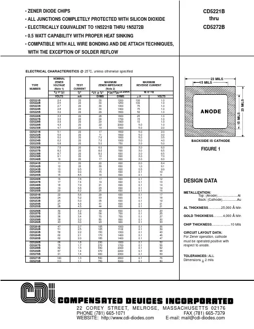
Solid-Electrolyte TANTALEX® CapacitorsHermetically-Sealed, Axial-Lead
FEATURES•These high performance, hermetically-sealed TANTALEX
®
capacitors have set the standard for solid-electrolytetantalum capacitors for more than three decades.
•High capacitance, low DCL, low dissipation factor andexceptional operating stability.
•Performance and reliability have been proven incommercial, industrial and military applications.
•Available in four case codes and capacitors and aresupplied with plastic-film insulation.
•Terminals are solid, tinned nickel wire leads.•The Military equivalent to the 150D is the CSR13 which isqualified to MIL-C-39003/01.
At + 85°C: Leakage current shall not exceed 10 times the
values listed in the Standard Ratings Tables.At +125°C: Leakage shall not exceed 15 times the valueslisted in the Standard Ratings Tables.Life Test: Capacitors shall withstand rated DCvoltage applied at + 85°C for 2000 hours or derated DCvoltage applied at + 125°C for 1000 hours.Following the life test:1. DCL shall not exceed 125% of the initial requirement.2. Dissipation Factor shall meet the initial requirement.3. Change in capacitance shall not exceed ± 5%.
元器件交易网www.cecb2b.comwww.vishay.com11
150DVishay Sprague
Document Number: 40015Revision 11-Jun-03For technical questions, contact tantalum@vishay.comMAX. DFMAX. DCL@ + 25˚CCAPACITANCECASEPART NUMBERPART NUMBER@ + 25˚C120 HZ(µF)CODECAP. TOL. ± 20%CAP. TOL. ±10%(µA)(%)
0.22A150D224X0006A2150D224X9006A20.520.27A_150D274X9006A20.520.33A150D334X0006A2150D334X9006A20.520.39A_150D394X9006A20.520.47A150D474X0006A2150D474X9006A20.520.56A_150D564X9006A20.520.68A150D684X0006A2150D684X9006A20.520.82A_150D824X9006A20.521.0A150D105X0006A2150D105X9006A20.521.2A_150D125X9006A20.541.5A150D155X0006A2150D155X9006A20.541.8A_150D185X9006A20.542.2A150D225X0006A2150D225X9006A20.542.7A_150D275X9006A20.543.3A150D335X0006A2150D335X9006A20.543.9A_150D395X9006A20.544.7A150D475X0006A2150D475X9006A20.545.6A_150D565X9006A20.546.8A150D685X0006A2150D685X9006A20.568.2B_150D825X9006B20.5610.0B150D106X0006B2150D106X9006B20.5612.0B_150D126X9006B20.5615.0B150D156X0006B2150D156X9006B21.0618.0B_150D186X9006B21.0622.0B150D226X0006B2150D226X9006B21.0627.0B_150D276X9006B21.0633.0B150D336X0006B2150D336X9006B21.0639.0B_150D396X9006B21.0647.0B150D476X0006B2150D476X9006B22.0656.0B_150D566X9006B22.0668.0R150D686X0006R2150D686X9006R23.0682.0R_150D826X9006R23.06100.0R150D107X0006R2150D107X9006R23.06120.0R150D127X0006R2150D127X9006R23.06150.0R150D157X0006R2150D157X9006R26.06180.0R150D187X0006R2150D187X9006R26.06220.0S150D227X0006S2150D227X9006S26.08270.0S150D277X0006S2150D277X9006S26.08330.0S150D337X0006S2150D337X9006S210.08
STANDARD RATINGS6 WVDC @ + 85°C, SURGE = 8 V . . . 4 WVDC @ + 125°C, SURGE = 5 V
ORDERING INFORMATIONSee Ratingsand CaseCodes Table.
150DMODEL224CAPACITANCEThis is expressed inpicofarads. The firsttwo digits are thesignificant figures.The third is the numberof zeros to follow.2STYLE NUMBER2 =Insulatedsleeve.ACASE CODE006DC VOLTAGE RATINGAT + 85°CThis is expressed involts. To completethe three-digit block,zeros precede thevoltage rating.X0CAPACITANCETOLERANCE
X0 = ± 20%X9 = ± 10%*X5 = ± 5%*Special order