Compact wideband multi-layer cylindrical dielectric resonator antennas
W.Huang and A.A.Kishk
Abstract:Homogenous dielectric resonator antennas(DRAs)have been studied widely and their
bandwidth have been reached to the possible upper limit.A new non-homogenous DRA,multi-
layer cylindrical DRA(MCDRA),is designed and fabricated to achieve wider bandwidth.The
antennas consist of three different dielectric discs,one on top of the other.Two different excitation
mechanisms are studied here.As much as66%of impedance bandwidth with a broadside radiation
pattern has been demonstrated using a50V coaxial probe placed off the antenna axis.More than
32%of impedance with a broadside radiation pattern has been achieved when the antenna is excited
by an aperture coupled50V microstrip feedline.Mode analysis is carried out to investigate the
natural resonance behaviours of the MCDRA structure.
1Introduction
The dielectric resonator(DR)was used as an energy storage device rather than a radiator in microwave circuits for many years[1].In1983,Long et al.[2]introduced it as an antenna,which is able to offer the advantages of compact size,low Ohmic losses and wider matching bandwidth over the microstrip antenna.The dielectric resonator antenna(DRA)is also simple to fabricate and easy to feed by different coupling mechanisms,such as coaxial probe,microstrip line coupled aperture,slotline,stripline and so on.Moreover,compared with the microstrip antenna,no surface wave losses are suffered because the DRA element is directly placed on the ground plane. However,because of the high dielectric constant and the high Q-factor,it has a limited impedance bandwidth of operation.At the early stage of development,simple shapes of the DRAs,such as a hemispherical DRA[3],a cylindrical DRA[4]and a rectangular DRA[5],were con-sidered.A bandwidth ranging from5to10%was achieved. Later,with improved knowledge of the antenna operation and the numerical tools,enhancements of the bandwidth were achieved using other shapes,such as truncated tetrahe-dron shape[6],split cone shape[7]and half-hemispherical shape DRAs[8].Although the bandwidth of the homo-geneous DRAs was improved to its possible upper limit,a much wider bandwidth was achieved by stacking two differ-ent DRAs[9,10],loading a high permittivity,low-pro?le dielectric disc on top of a conventional homogeneous DRA in[11]and plugging an inner core into the lower stacked part[12].In addition,in[13],multisegment DRAs are developed to enhance its coupling to a microstrip line by inserting one or more thin segments of different per-mittivity substrates under a DRA of low permittivity. Here,a wideband multi-layer cylindrical DRA (MCDRA)is designed and fabricated by simply placing three different dielectric discs of the same diameter,one on top of the other,as shown in Fig.1.Three dielectric discs are made of standard available dielectric substrate materials in our laboratory:Rogers RT/Duroid6010 (1r?10.2)with thickness2.5mm,Poly?on POLYGUIDE (1r?2.32)with thickness 3.35mm and Rogers RT/ Duroid6006(1r?6.15)with thickness 2.5mm.The shape of the MCDRA can be considered as not physically deformed but electrically deformed because of the different dielectric constant of each disc.Therefore compared with the equivalent homogenous DRA,the MCDRA supports several broadside radiating modes with close resonant fre-quencies,which provide wider bandwidths.Also,the MCDRA resides on a ground plane,which does not support surface waves as multisegment DRAs do,so it will not suffer the surface wave losses.The fabrication is also simple since the thickness of each disc is the same as the materials available in market.
In Section2,MCDRAs with different stack order are per-formed numerically in order to?nd the optimal order.A coaxial-probe-fed MCDRA geometry with optimal order is described for both simulation and measurements cases. Also,the measured re?ection coef?cients and radiation pat-terns are veri?ed with the simulated results.In Section3,an aperture-coupled microstrip-line-fed MCDRA is described and the measured voltage standing wave ratio(VSWR)is veri?ed experimentally.The simulated radiation patterns are also demonstrated.In Section4,mode analyses are dis-cussed to explain the natural resonance behaviour of the MCDRA.In the last section,conclusions are provided.
2Coaxial probe excitation
2.1Antenna geometry and fabrication
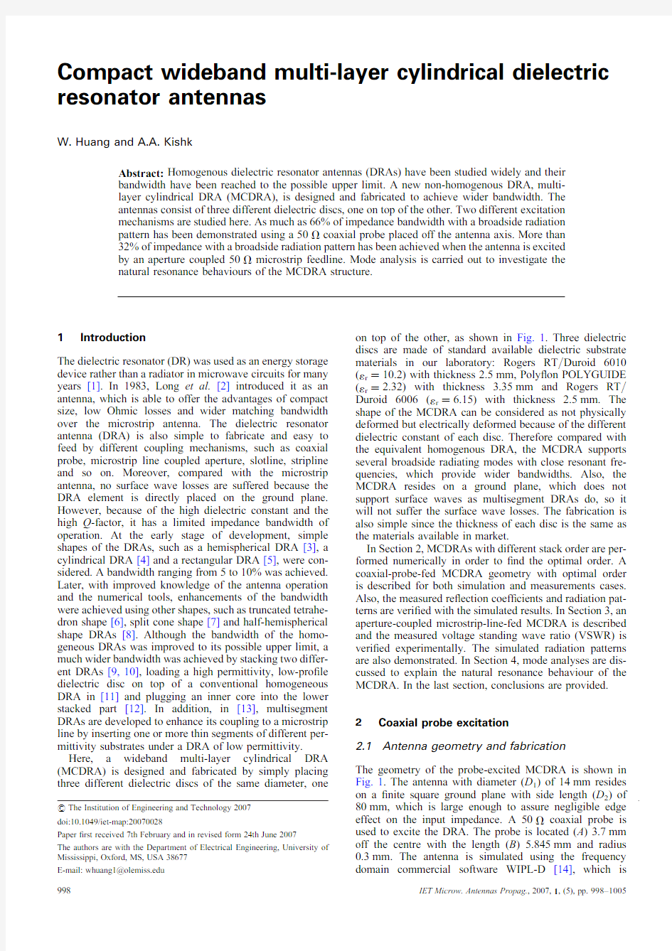
The geometry of the probe-excited MCDRA is shown in Fig.1.The antenna with diameter(D1)of14mm resides on a?nite square ground plane with side length(D2)of 80mm,which is large enough to assure negligible edge effect on the input impedance.A50V coaxial probe is used to excite the DRA.The probe is located(A)3.7mm off the centre with the length(B)5.845mm and radius 0.3mm.The antenna is simulated using the frequency domain commercial software WIPL-D[14],which is
#The Institution of Engineering and Technology2007
doi:10.1049/iet-map:20070028
Paper?rst received7th February and in revised form24th June2007
The authors are with the Department of Electrical Engineering,University of Mississippi,Oxford,MS,USA38677
E-mail:whuang1@https://www.doczj.com/doc/fe5245699.html,
based on the surface integral equations and method of moments.In order to provide some practical insight into the design of the MCDRA,different stack orders for the dielectric discs with the same dimensions are performed numerically.The calculated bandwidths are shown in Table 1.It was found that the optimal arrangement for the three dielectric discs from top to bottom are:(1r1)10.2,(1r2)2.32,(1r3)6.15,and loss tangent (tan d 1)0.0023,(tan d 2)0.0002,(tan d 3)0.0019.The corresponding thicknesses of the discs are (H 1) 2.5mm,(H 2) 3.35mm and (H 3)2.5mm,respectively.
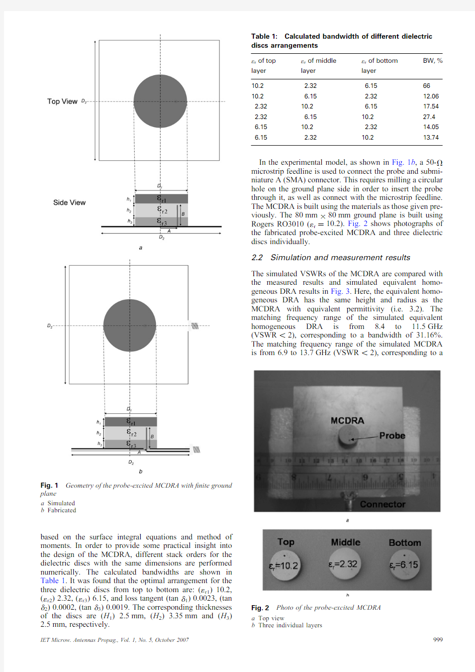
In the experimental model,as shown in Fig.1b ,a 50-V microstrip feedline is used to connect the probe and submi-niature A (SMA)connector.This requires milling a circular hole on the ground plane side in order to insert the probe through it,as well as connect with the microstrip feedline.The MCDRA is built using the materials as those given pre-viously.The 80mm ?80mm ground plane is built using Rogers RO3010(1r ?10.2).Fig.2shows photographs of the fabricated probe-excited MCDRA and three dielectric discs individually.2.2
Simulation and measurement results
The simulated VSWRs of the MCDRA are compared with the measured results and simulated equivalent homo-geneous DRA results in Fig.3.Here,the equivalent homo-geneous DRA has the same height and radius as the MCDRA with equivalent permittivity (i.e. 3.2).The matching frequency range of the simulated equivalent homogeneous DRA is from 8.4to 11.5GHz (VSWR ,2),corresponding to a bandwidth of 31.16%.The matching frequency range of the simulated MCDRA is from 6.9to 13.7GHz (VSWR ,2),corresponding to a
Table 1:Calculated bandwidth of different dielectric discs arrangements
1r of top layer 1r of middle layer 1r of bottom layer BW,%
10.2 2.32 6.156610.2 6.15 2.3212.062.3210.2 6.1517.542.32 6.1510.227.46.1510.2 2.3214.056.15
2.32
10.2
13.74Fig.2Photo of the probe-excited MCDRA
a Top view
b Three individual
layers
Fig.1Geometry of the probe-excited MCDRA with ?nite ground plane
a Simulated
b Fabricated
bandwidth of 66%.The matching frequency range of the measured result is from 6.95to 12.3GHz (VSWR ,2),corresponding to a bandwidth of 60%.Both the simulated and measured MCDRAs have a much wider bandwidth than the homogeneous equivalent DRA.Good agreement is achieved between the simulated and measured MCDRA results.The slightly smaller measured bandwidth compared with the simulated bandwidth may be because of the induc-tance effect of the probe inside of the substrate below the ground plane and the fringing capacitance effect at the end of the microstrip line.To determine the effect of probe feed location (A ),a parametric study of the dis-tance between probe location and the center of MCDRA is shown at Fig.4.It can be found that the location of the probe impacts the antenna’s impedance matching,but has little effect on the resonant frequency.Moreover,the effects of probe length (B )are studied in Fig.5.As expected,longer probe have lower resonant frequencies.In addition,the antenna matching changes,but this can be tuned by adjusting other antenna parameters.
Fig.6provides the simulated and measured co-polarised and cross-polarised radiation patterns of the MCDRA in the E-plane and H-plane at 7,8and 9.5GHz,respectively.The measured co-polarisation E-plane patterns are very similar to the simulated one,but the measured cross-polarisation patterns in the E-plane have higher levels than the simulated
cross-polarisation patterns.This could be related to the con-nector effect and the rigid cables used to mount the antenna on the tower of the anechoic chamber.The backside micro-strip feedline also causes the measured H-plane co-polarisation patterns to have higher back-radiation than the simulated ones,and the measured H-plane cross-polarisation patterns to have some degradation.The com-puted results show good radiation patterns up to 10.5GHz.Some higher-order modes with non-broadside radiation patterns are excited and disturb the radiation pattern axial symmetry when the frequency is higher than 10.5GHz.The calculated peak gain is 5.76dBi at 8.8GHz.3Aperture-coupled excitation 3.1
Antenna geometry and fabrication
In addition to probe excitation,a microstrip-line-coupled aperture can also feed the MCDRA.The geometry of the aperture-coupled MCDRA is shown in Fig.7.The three dielectric discs have the same permittivity and dimensions as in Section 2.The antenna resides on a ?nite ground plane with dimension 90mm ?120mm.The slot width is (W st )0.6mm,which is much less than l g /20,and its length (L sl )10mm is experimentally adjusted to provide optimum coupling.The appropriate microstrip feedline width (W m )1.72mm was chosen to obtain a 50-V trans-mission line at the design frequency.The open circuit stub is used to improve the impedance matching.The stub length (L st )5.72mm was set to approximately one-quarter of a guide wavelength and is located (L offset )3.45mm off the centre of the slot.The three dielectric discs were glued to each other and to the ground plane over the slot using 3M Spray Mount Artist’s Adhesive.Since the glue is spray-type,its volume is negligible.Also,because the proposed antenna is a wideband antenna,the effect of the glue is not noticeable.The antenna is simulated using the Ansoft high-frequency structure simulator (HFSS)[15],which is based on the ?nite element method.Fig.8shows the photograph of a fabricated aperture-coupled MCDRA.3.2
Simulation and measurement results
Fig.9shows the simulated and measured VSWR curves.The frequency bandwidth of the simulated
aperture-coupled
Fig.3Comparison of measured and simulated VSWR of probe-excited
MCDRA
Fig.4Magnitude of the re?ection coef?cients as function of the distance of probe location from the centre of
MCDRA
Fig.5Magnitude of the re?ection coef?cients as function of the probe length
MCDRA for a VSWR ?2criteria is from 6.2to 8.5GHz,corresponding to a bandwidth of 31.3%.The bandwidth of the measured result for a VSWR ?2criterion is from 6.15to 8.5GHz,corresponding to a bandwidth of 32.3%.The calculated and measured values are in good agreement.
It should be noted that there are some fabrication tolerances,such as probe length and probe locations as shown in the parametric study part,affected the impedance matching.Also from the experiment,it has been found that,unlike aperture-coupled microstrip patch antenna,
precise
Fig.6Measured and simulated radiation patterns (10dB /div)of E /H-plane co-polar and cross-polar ?eld of the probe-excited MCDRA
a f ?7.0GHz
b f ?7.0GHz
c f ?8.0GHz
d f ?8.0GHz
e
f ?9.5GHz f
f ?9.5GHz
positioning of the MCDRA antenna over the slot is not required,which means that good coupling can be attained without the requirement for precise aligning the antenna over the slot.
Fig.10provides both the simulated and measured co-polarised and cross-polarised radiation patterns of aperture-coupled MCDRA in the E-plane and H-plane at 6,7and 8GHz,respectively.The cross-polarisation is much lower than the probe-fed case because of the suppres-sion of the zero-order mode.The calculated peak gain is 5.5dBi at 8GHz.4
Mode analysis
To investigate the natural resonance behaviours of the MCDRA structure,mode analyses are carried out using Ansoft HFSS eigenmode solver,which consists of three dielectric discs,one on top of the other.The
dimensions
Fig.7Geometry of the aperture-coupled MCDRA with ?nite ground
plane
Fig.8Photo of the aperture-coupled MCDRA
a Top view
b Bottom
view
Fig.9Comparison of the measured and simulated VSWR of the aperture-coupled MCDRA
and materials are the same as those previous given.In HFSS,the eigenmode solver does not support radiation boundaries or perfect matched layer (PML)boundary because it is dif?cult to ?nd the resonances for low
Q -factor cases.However,eigensolutions can be obtained when the whole model is enclosed in a closed conducting cavity [15].Since the cavity is about two to three times the size of the DRA resonator [1],the resonant frequencies
of
Fig.10Measured and simulated radiation pattern (10dB /div)of E /H-plane co-polar and cross-polar ?eld of the aperture-coupled MCDRA
a f ?6GHz
b f ?6GHz
c f ?7GHz
d f ?7GHz
e
f ?8GHz f
f ?8GHz
the resonator are close to the isolated case.Therefore the cavity modes are able to distinguish from the DR modes. It should also be noted that eigenmode is the nature mode in the structure and is independent of source.The resonant frequencies of the natural modes and full complex vector?eld can be obtained from the output results of HFSS.Table2illustrates the?rst12 eigensolutions obtained starting at0.1GHz.The?rst resonance appears around7.14GHz.These modes could be excited by proper sources at the proper locations with different strengths.However,the zeroth-order mode can be coupled by the probe but not by the centred slot. Based on our experiences,more excited modes could increase the antenna matching bandwidth,but the radiation bandwidth could be deteriorated by the presence of the high-order modes.The following mode analyses are pre-sented to explain such performance.Fig.11illustrates the vector?eld distributions of TE-,TM-,HEM-and cavity-type modes existing among the?rst12eigensolutions,Table2:First12eigensolutions obtained starting at 0.1GHz
Eigenmode Frequency,GHz Type
17.14HEM
28.39HEM
38.63TM
48.65TE
59.96cavity
610.15HEM
711.07TM
811.42TE
911.49TM
1012.13cavity
1112.79cavity
1212.91
TE
Fig.11Vector?eld distributions
a,b TE-type at8.65GHz
c,d TM-type at11.07GHz
e,f HEM-type at7.14GHz
g,h Cavity-type at9.96GHz
where Figs.11a,c,e and g are x–y-plane view and Figs.11b,d,f and h are x–z-plane view.From the vector ?eld distributions shown in Fig.11,we can learn which mode could be coupled to probe or slot.For example,the TE-type mode at8.65GHz shown in Figs.11a and b could not coupled to the probe,but to a non-centred narrow slot.The TM-type mode at11.07GHz shown at Figs.11c and d can be coupled to a probe and not to a slot.Based on the vector?elds of all the12modes,we con-clude that more modes can be coupled by coaxial probe than slot,which explains the wider bandwidth due to the probe excitation rather than aperture-coupled excitation. However,only4of the12modes’vector?elds are demon-strated for the sake of brevity.It was also presented to demonstrate that the natural modes existing in the MCDRA structure are more complicated than a simple disc resonator case.For example,for a simple disc resonator case,the ground plane usually suppresses the TE modes. But for the MCDRA case,some TE modes could be sup-ported with the presence of the ground plane,because their electric?eld has z-variation which allows the electric ?eld normal to the ground plane also with zero tangential components at the boundary of the ground plane,as shown in Fig.11d.
5Conclusion
A compact wideband MCDRA was designed and fabri-cated.Around60%of bandwidth was achieved using coaxial probe feeding.The simulated and measured results are in good https://www.doczj.com/doc/fe5245699.html,pared with other wide-band DRAs,the MCDRA has much wider bandwidth, surface wave losses above the ground plane and relatively simpler and easier fabrication.Another excitation mechan-ism–aperture-coupled microstrip feedline–was used and more than30%bandwidth was achieved.Simulated and measured results also have good agreement.Mode analysis showed the resonance behaviour of the MCDRA structure and explained that wider bandwidth can be sup-ported by the probe-excited MCDRA than aperture-coupled MCDRA.6Acknowledgment
This work was supported by the National Science Foundation under Grant No.ECS-524293.
7References
1Kajfez,D.,and Guillon,P.:‘Dielectric resonators’(Artech House,1986) 2Long,S.A.,McAllister,M.W.,and Chen,L.C.:‘The resonant cylindrical dielectric cavity antenna’,IEEE Trans.Antennas Propag.,1983,31,(3),pp.406–412
3Kishk, A.A.,Zhou,G.,and Glisson, A.W.:‘Analysis of dielectric-resonator antennas with emphasis on hemispherical structures’,IEEE Antennas Propag.Mag.,1994,36,(2),pp.20–31 4Kishk,A.A.,Junker,J.P.,and Glisson,A.W.:‘Input impedance of dielectric resonator antennas excited by a coaxial probe’,IEEE Trans.Antennas Propag.,1994,42,(7),pp.960–966
5Ittipiboon,A.,Mongia,R.K.,Antar,Y.M.M.,Bhartia,P.,and Cuhaci, M.:‘An integrated rectangular dielectric resonator antenna’.Proc.
IEEE Antennas Propag.Int.Symp.,1993,pp.604–607
6Kishk,A.A.:‘Wide-band truncated tetrahedron dielectric resonator antenna excited by a coaxial probe’,IEEE Trans.Antennas Propag., 2003,51,(10,Pt2),pp.2913–2917
7Kishk,A.A.,Yan,Y.,and Glisson,A.W.:‘Conical dielectric resonator antennas for wide-band applications’,IEEE Trans.Antennas Propag., 2002,50,(4),pp.469–474
8Guha,D.,and Antar,Y.M.M.:‘New half-hemispherical dielectric resonator antenna for broadband monopole-type radiation’,IEEE Trans.Antennas Propag.,2006,54,(12),pp.3621–3628
9Kishk,A.A.,Ahn,B.,and Kajfez,D.:‘Broadband stacked dielectric resonator antennas’,IEE Electron.Lett.,1989,25,(18),pp.1231–1233 10Kishk,A.A.,Zhang,X.,Glisson,A.W.,and Kajfez,D.:‘Numerical analysis of stacked dielectric resonator antennas excited by a coaxial probe for wideband applications’,IEEE Trans.Antennas Propag.,2003,51,(8),pp.1996–2006
11Lo,H.Y.,Leung,K.W.,Luk,K.M.,and Yung,E.K.N.:‘Low-pro?le equilateral-triangular dielectric resonator antenna of very high permittivity’,IEE Electron.Lett.,1999,35,(25),pp.2164–2166
12Walsh,A.G.,DeYoung,C.S.,and Long,S.A.:‘An investigation of stacked and embedded cylindrical dielectric resonator antennas’, IET Antennas Wirel.Propag.Lett.,2006,5,(1),pp.130–133
13Petosa,A.,Simons,N.,Siushansian,R.,Ittipiboon,A.,and Cuhaci, M.:‘Design and analysis of multisegment dielectric resonator antennas’,IEEE Trans.Antennas Propag.,2000,48,(5),pp.738–742 14Kolundzija,B.,et al.:‘WIPL-D Professional v5.1electromagnetic modeling of composite metallic and dielectric structures:software and users manual’(WIPL-D Ltd.,2004)
15‘Ansoft high-frequency structure simulator user’s guide,version10.0’(Ansoft Corporation,USA,2005)
介质谐振器与介质谐振器天线的建模与仿真分析汇总
第3章介质谐振器与介质谐振器天线的建模与仿真分析 3.1介质谐振器 介质谐振器的流程图: 设计 设置 创建 创 检 保存 设 仿 查看计 创建 参数 参数
3.1.1介质谐振器的建模 介质谐振器的模型有很多中,本文主要是以圆柱形介质谐振器为参考,其中,介质谐振器的尺寸
均是由本人视个人情况设定。 本模型由三部分组成:谐振腔、谐振介质和基片, 如图所示: 谐振 谐振 谐振 3.1.2谐振器的设计与仿真分析 (1)开始前的准备工作 上网下载电磁波仿真系统HFSS软件,进行安装。 打开HFSS软件桌面快捷方式,启动HFSS软件。新建一个工程,名称 为yuancong.hfss ,然后设计解决方案类型。在HFSS软件中,具有三种求解方 法。分别是受驱模式求解、受驱终端求解和本征模求解。下面是三种求解方式 的区别: 本征模求解:计算结构的本征模或谐振是一般采用本征模求解方式。本征 模求解可算出结构的谐振频率和在这些谐振频率出对应的场,也可计算出品质 因数。因为本征模问题不包含端口和源,所以介质谐振器运用的求解方式是本 征模求解方式。 受驱模式求解:想用HFSS计算基于微波传输带、波导、传输线等被动高 频结构的基于模式的S参数时,选用Driven Modal。S 参数解决将用一系列波
导模的入射和反射能量来表示。 受驱终端求解:想用HFSS计算基于终端的多导体传输线端口的S参数时,采用受驱终端求解。 (2)设计模型单位 选择软件的单位以毫米为单位。 (3)创建空气腔 选择菜单项创建空气腔,其圆柱体的基坐标为(x=0,y=0,z=0),并且键入半径为15mm,高度为10mm。并且勾选显示框架项。 (4)创建新材料 由于介质谐振器是由高介电常数和低损耗的介质材料制成,所以要创建高介电常数的材料。 ε=36,命我们在三维模型材质中创建新材质,其中,谐振介质的介电常数 r 名为DielRes.在实际天线设计中,谐振器要放在介质基片之上,基片下面是接地板,接地板如果与谐振器较近就会对谐振频率和品质因数有影响,而且谐振器材料的介电常数必须远大于基片的介电常数。所以设置谐振基片的介电常数 ε=9.6.命名为subs。 r (5)创建基片和介质 创建基片位置为(x=0,y=0,z=0),其中半径为15mm,高度为-1mm。命名为substrate。设置材料为subs 创建介质位置为(x=0,y=0,z=0),其中半径为5mm。高度为5mm。设置材料为DielRes。 (6)检查模型设置 我们已经建立了完整的模型,分析之前唯一没做的是设定边界条件,我们应用系统默认的边界为理想电边界。由于本征模算法不需要端口激励,所以我们不设置激励。 通过菜单项中的边界显示,得出如图结果: (7)设置分析 建好模型后,接下来是使用HFSS软件的分析功能来分析模型的微波性能,首先添加分析功能,然后设置器件所要工作的工作频率。完成设置后,开始分析模型。
第3章介质谐振器与介质谐振器天线的建模与仿真分析 3.1介质谐振器 介质谐振器的流程图: 设计单位 设置默认材 料 创建空气腔 创建介质 检查模型 保存工程 设置分析 仿真 查看计算结果 创建场覆盖图 参数扫描 参数扫描结
3.1.1介质谐振器的建模 介质谐振器的模型有很多中,本文主要是以圆柱形介质谐振器为参考,其中,介质谐振器的尺寸均是由本人视个人情况设定。 本模型由三部分组成:谐振腔、谐振介质和基片,如图所示: 3.1.2谐振器的设计与仿真分析 (1)开始前的准备工作 上网下载电磁波仿真系统HFSS 软件,进行安装。 打开HFSS 软件桌面快捷方式,启动HFSS 软件。新建一个工程,名称为yuancong.hfss ,然后设计解决方案类型。在HFSS 软件中,具有三种求解方法。分别是受驱模式求解、受驱终端求解和本征模求解。下面是三种求解方式的区别: 本征模求解:计算结构的本征模或谐振是一般采用本征模求解方式。本征模求解可算出结构的谐振频率和在这些谐振频率出对应的场,也可计算出品质因数。因为本征模问题不包含端口和源,所以介质谐振器运用的求解方式是本征模求解方式。 受驱模式求解:想用HFSS 计算基于微波传输带、波导、传输线等被动高频结构的基于模式的S 参数时,选用Driven Modal 。S 参数解决将用一系列波导模的入射和反射能量来表示。 受驱终端求解:想用HFSS 计算基于终端的多导体传输线端口的S 参数时,采用受驱终端求解。 (2)设计模型单位 选择软件的单位以毫米为单位。 (3)创建空气腔 选择菜单项创建空气腔,其圆柱体的基坐标为(x=0,y=0,z=0),并且键入半径为15mm ,高度为10mm 。并且勾选显示框架项。 谐振腔 谐振介质 谐振器基片
介质谐振天线 介质谐振天线(dielectric resonator antenna) 随着无线通信事业的飞速发展,对于天线的小型化、宽频带、低损耗等性能提出了更高的要求。虽然各种各样的微带天线因其低剖面、轻质量等优点,已经得到了深入的研究和广泛的应用,但由于在高频段金属欧姆损耗高和在低频段天线几何尺寸大这两个关键性技术瓶颈的存在,其发展和应用受到了一定的限制。近年来,一种新型天 线——介质谐振器天线由于良好的性能而受到了广泛的关注和研究。 介质谐振器早期主要作为一种能量的存储装置,直到1983年美国休斯顿大学的郎教授发表的第一篇关于圆柱形介质谐振器天线的文章后,才引起人们对介质谐振器天线的关注。介质谐振器天线是一种谐振式天线,由低损耗的微波介质材料构成,它的谐振频率由谐振器尺寸、形状和相对介电常数所决定。且介质谐振器具有其自身特有的优势: (1)介电常数的选择范围很大(6-140),允许设计者灵活控制尺寸和带宽; (2)介质谐振器天线通过整个谐振器表面(除了与地板接触的那个面之外)进行辐射,因为没有导体和表面波损耗而自身介质损耗又小,其辐射效率很高(>95%); (3)介质谐振器的形状有多种,设计具有很大的灵活性; (4)介质谐振器天线馈电方式较多:探针,缝隙耦合,微带线,共面波导,介质镜像波导等,且其它天线的馈电技术都比较容易地应用到介质谐振器天线中; (5)可以激励起多种模式,针对不同的覆盖要求可产生宽边或圆锥型的辐射模式; (6)介质谐振器天线加工简单,成本较低,便于集成设计。基于以上优点,介质谐振器天线已广泛应用于Bluetooth、PHS、WLAN等通信系统中,并在雷达系统、移动卫星通信、相控阵天线等诸多领域显示出潜在的应用价值。 介质谐振器天线研究方向 近年来围绕介质谐振器天线的研究主要集中在以下几个方面: 1、圆极化介质谐振器天线 2、高增益介质谐振器天线 3、宽频带介质谐振器天线 4、双极化介质谐振器天线
微波介质谐振器的发展 和应用前景 公司内部编号:(GOOD-TMMT-MMUT-UUPTY-UUYY-DTTI-
微波介质谐振器的发展和应用前景 成都微波技术支持工程师:郑国全 一、微波是什么 微波是指频率300MHz-3000GHz的电磁波,是无线电波中的一个频段,即波长在1米(不含1米)到0.1毫米之间的电磁波,是分米波、厘米波、毫米波和亚毫米波的统称。微波频率比一般的无线电波频率高,通常也称为“超高频电磁波”,微波作为一种电磁波具有波粒二象性。 二、微波的特性 微波的基本性质通常呈现为穿透、反射、吸收三个特性。对于玻璃、塑料和瓷器,微波几乎是穿越而不被吸收。对于水和食物等就会吸收微波而使自身发热。而对金属类东西,则会反射微波。从电子学和物理学观点来看,微波这段电磁频谱具有不同于其他波段的如下重要特点: 穿透性 微波比其它用于辐射加热的电磁波,如红外线、远红外线等波长更长,因此具有更好的穿透性。微波透入介质时,由于介质损耗引起的介质温度的升高,使介质材料内部、外部几乎同时加热升温,形成体热源状态,大大缩短了常规加热中的热传导时间,物料内外加热均匀一致。 选择性加热 物质吸收微波的能力,主要由其介质损耗因数来决定。介质损耗因数大的物质对微波的吸收能力就强,相反,介质损耗因数小的物质吸收微波的能力也弱。由于各物质的损耗因数存在差异,微波加热就表现出选择性加热的特点。物质不同,产生的热效果也不同。水分子属极性分子,介电常数较大,其介质损耗因数也很大,对微波具有强吸收能力。而蛋白质、碳水化合物等的介电常数相对较小,其对微波的吸收能力比水小得多。因此对于食品,含水量的多少对微波加热效果影响很大。 热惯性小 微波对介质材料是瞬时加热升温,能耗也很低。另一方面,微波的输出功率随时可调,介质温升可无惰性的随之改变,不存在“余热”现象,极有利于自动控制和连续化生产的需要。 似光性和似声性 微波波长很短,比地球上的一般物体(如飞机,舰船,汽车建筑物等)尺寸相对要小得多,或在同一量级上。使得微波的特点与几何光学相似,即所谓的似光性。因此在微波频段工作,能使电路元件尺寸减小,系统更加紧凑。可以制成体
介质谐振器的工作原理 我们目前所接触到的最基本的介质器件是介质谐振器。要想了解介质谐振器的工作原理首先要了解金属波导与谐振腔。 一、 金属波导的一般特性 传输电磁能量或电磁信号的途径可分为两类,一类是电磁波在空间或大气中的传播,另一类是电磁波沿波导系统的传播。人类最初应用的电磁波导波系统是双线传输线,双线传输线主要用在频率较低的场合,当使用频率逐步提高时,双线传输线的传输损耗以及辐射损耗急剧的增加,为了克服辐射损耗,采用了同轴线结构。但是同轴线中所采用的模式仍然是TEM模,必须有内外两根导体,到了频率更高时内导体的损耗变得很严重。在微波频段即分米波段和厘米波段人们发现,用一根中空的金属管来传输电磁波是可行的和方便的。在空管中不可能传播TEM模式,因此采用TE模或TM模,这就是金属波导或称为波导管。到了短毫米波段及亚微毫米波段金属波导的截面积尺寸太小,加工不易,因此采用介质波导作为传输系统。在光波段使用光学纤维和光波导也是介质波导。光学纤维简称光纤现在已成为传输电磁信号的主要手段。 为了近似地实现短路面的边界条件可以用具有高导电率的导体即金属构成的边界面,这样就形成金属波导或称波导管。金属波导可以由一根波导管构成,也可以由多根波导管构成。略去导体表面损耗时,可将边界看作短路面。 波导波的特点是存在一个截止频率,当工作频率高于截止频率时,纵方向为快行波,横方向为驻波,工作频率低于截止频率时,纵方向成为衰减场或渐消场,横方向仍然为驻波。 金属波导的传播特性为ωc=T/(με)1/2 =cT/(με) 1/2或Fc= cT/2∏(με) 1/2临界状态下,电磁波在介质中的波长就是横向波长,即λT=2∏/T=1/fc(με)1/2相应的临界状态下真空中的波长称为临界波长。 当电磁波的角频率大于波长的临界角频率时,电磁波可在波导中传播,反之,波导是截止的。临界角波数决定于波导的截面形状和尺寸。 二、 金属波导的波阻抗 金属壁是由良导体构成而非理想导体,因此电磁波在波导中传播时一定会有功率损耗,从而造成电磁波沿传播方向上的衰减。其衰减常数为: а=1/4σδ*H2dL/P; 式中,L为波导的横截面的闭合边界线;P为波导中传输的功率流,σ为波导壁的导电
Compact wideband multi-layer cylindrical dielectric resonator antennas W.Huang and A.A.Kishk Abstract:Homogenous dielectric resonator antennas(DRAs)have been studied widely and their bandwidth have been reached to the possible upper limit.A new non-homogenous DRA,multi- layer cylindrical DRA(MCDRA),is designed and fabricated to achieve wider bandwidth.The antennas consist of three different dielectric discs,one on top of the other.Two different excitation mechanisms are studied here.As much as66%of impedance bandwidth with a broadside radiation pattern has been demonstrated using a50V coaxial probe placed off the antenna axis.More than 32%of impedance with a broadside radiation pattern has been achieved when the antenna is excited by an aperture coupled50V microstrip feedline.Mode analysis is carried out to investigate the natural resonance behaviours of the MCDRA structure. 1Introduction The dielectric resonator(DR)was used as an energy storage device rather than a radiator in microwave circuits for many years[1].In1983,Long et al.[2]introduced it as an antenna,which is able to offer the advantages of compact size,low Ohmic losses and wider matching bandwidth over the microstrip antenna.The dielectric resonator antenna(DRA)is also simple to fabricate and easy to feed by different coupling mechanisms,such as coaxial probe,microstrip line coupled aperture,slotline,stripline and so on.Moreover,compared with the microstrip antenna,no surface wave losses are suffered because the DRA element is directly placed on the ground plane. However,because of the high dielectric constant and the high Q-factor,it has a limited impedance bandwidth of operation.At the early stage of development,simple shapes of the DRAs,such as a hemispherical DRA[3],a cylindrical DRA[4]and a rectangular DRA[5],were con-sidered.A bandwidth ranging from5to10%was achieved. Later,with improved knowledge of the antenna operation and the numerical tools,enhancements of the bandwidth were achieved using other shapes,such as truncated tetrahe-dron shape[6],split cone shape[7]and half-hemispherical shape DRAs[8].Although the bandwidth of the homo-geneous DRAs was improved to its possible upper limit,a much wider bandwidth was achieved by stacking two differ-ent DRAs[9,10],loading a high permittivity,low-pro?le dielectric disc on top of a conventional homogeneous DRA in[11]and plugging an inner core into the lower stacked part[12].In addition,in[13],multisegment DRAs are developed to enhance its coupling to a microstrip line by inserting one or more thin segments of different per-mittivity substrates under a DRA of low permittivity. Here,a wideband multi-layer cylindrical DRA (MCDRA)is designed and fabricated by simply placing three different dielectric discs of the same diameter,one on top of the other,as shown in Fig.1.Three dielectric discs are made of standard available dielectric substrate materials in our laboratory:Rogers RT/Duroid6010 (1r?10.2)with thickness2.5mm,Poly?on POLYGUIDE (1r?2.32)with thickness 3.35mm and Rogers RT/ Duroid6006(1r?6.15)with thickness 2.5mm.The shape of the MCDRA can be considered as not physically deformed but electrically deformed because of the different dielectric constant of each disc.Therefore compared with the equivalent homogenous DRA,the MCDRA supports several broadside radiating modes with close resonant fre-quencies,which provide wider bandwidths.Also,the MCDRA resides on a ground plane,which does not support surface waves as multisegment DRAs do,so it will not suffer the surface wave losses.The fabrication is also simple since the thickness of each disc is the same as the materials available in market. In Section2,MCDRAs with different stack order are per-formed numerically in order to?nd the optimal order.A coaxial-probe-fed MCDRA geometry with optimal order is described for both simulation and measurements cases. Also,the measured re?ection coef?cients and radiation pat-terns are veri?ed with the simulated results.In Section3,an aperture-coupled microstrip-line-fed MCDRA is described and the measured voltage standing wave ratio(VSWR)is veri?ed experimentally.The simulated radiation patterns are also demonstrated.In Section4,mode analyses are dis-cussed to explain the natural resonance behaviour of the MCDRA.In the last section,conclusions are provided. 2Coaxial probe excitation 2.1Antenna geometry and fabrication The geometry of the probe-excited MCDRA is shown in Fig.1.The antenna with diameter(D1)of14mm resides on a?nite square ground plane with side length(D2)of 80mm,which is large enough to assure negligible edge effect on the input impedance.A50V coaxial probe is used to excite the DRA.The probe is located(A)3.7mm off the centre with the length(B)5.845mm and radius 0.3mm.The antenna is simulated using the frequency domain commercial software WIPL-D[14],which is #The Institution of Engineering and Technology2007 doi:10.1049/iet-map:20070028 Paper?rst received7th February and in revised form24th June2007 The authors are with the Department of Electrical Engineering,University of Mississippi,Oxford,MS,USA38677 E-mail:whuang1@https://www.doczj.com/doc/fe5245699.html,
采用介质谐振器阵列天线产生OAM波束的新方式 摘要:轨道角动量(OAM)技术为无线通信系统提供了新的调制维度,成为解决频谱资源短缺问题的有效方法。提出了一种新颖的OAM阵列天线,利用介质谐振器阵列天线产生OAM波束。仿真结果表明,此OAM阵列天线半径的大小直接影响OAM 波束的效果,同时合适的馈电位置以及馈电方式在一定程度上可以改善中央空域问题和提高OAM波束远距离传输质量。此OAM阵列天线体积小、介质材料选取广泛,能够解决环形OAM微带阵列天线高频段辐射阵元损耗高、低频段几何尺寸大的难题,对OAM阵列天线在未来无线通信领域的实际应用提供了新的参考价值。 0 引言 近年来,频谱资源利用率低已成为无线通信技术发展迫切需要解决的瓶颈问题,多种分集技术(如空间分集、极化分集、频率分集等)已经成功被用来传输数据,以提高频谱效率。但传统的调制技术仅使用频率、时间、码型和空间等资源作为自由度,它们的调制能力是有限的。OAM涡旋电磁波的复用技术可以在同一频点下实现多路信号的同时传输[1],它作为一个有发展前景的方法,对解决频谱利用率低、频谱资源短缺等问题提供了一定的研究思路,带来了不可估量的研究价值。 轨道角动量(Orbital Angular Momentum,OAM)表征出具有相位因子为exp(jlφ)的螺旋相位波前结构的自然属性[2]。OAM作为一种不同于相位、幅度、极化的调制维度被引入到无线通信中,可以有效地提高通信系统的容量和效率。螺旋透镜[3]、超表面[4]、螺旋相位板[5]等光领域OAM波束的产生方法很难全部应用于微波段的无线通信系统中,探索合适的微波段OAM波束产生方式显得尤为重要。2013年,TAMBURINI F等人基于螺旋抛物面天线进行了OAM无线通信实验[6],证明了利用OAM涡旋电磁波进行无线通信以及增加无线传输容量的可行性;2014年,BAI Q等人利用8个相同的矩形微带贴片组成圆形相控阵天线产生OAM波束[7];2015年,BAI X等人用三极化圆喇叭阵列天线生成了OAM波束[8];2016年,KANG M S等人采用配置了8路均匀功率分配器的圆形阵列天线产生模式数l=1的OAM波束[9]。此后,更多关于OAM天线和OAM波束生成的方法被
305 8 DRD型 o TE 01δ模式谐振器 (圆板型/柱型) 的有效范围 可提供附支撑架的TE模式谐振器和调好频率的谐振器。 DRR060型铜电极DRR040型铜电极 DRR020型铜电极 DRR030型铜电极o TEM模式谐振器有效范围 in mm L:取决于频率 高频元件/组件 !注意事项? 本产品目录所记载的产品规格,因受篇幅的限制,只提供了主要产品资料。在您订购前,必须确认规格表内容,或者互换协商定案图。 尤其,有些产品请务必阅读其品级,或!注意事项 (保管、使用环境、品级上的注意事项、装配时的注意事项、使用时的注意事项),否则有可能出现冒烟、起火等情况。 ? 产品检索引擎 (http://search.murata.co.jp/) 或产品目录数据库 (https://www.doczj.com/doc/fe5245699.html,/cn/catalog/) 上登载有详细规格,因此,在索取规格表,或互换协商定案图之前可阅览其详细规格。
306 8 1) 频率温度系数。 2) 谐振频率的公差 (P: ±0.7%最大值; K: ±0.7%最大值)。3) Qu的值取决于频率范围的下限。 接上页。 高频元件/组件 !注意事项? 本产品目录所记载的产品规格,因受篇幅的限制,只提供了主要产品资料。在您订购前,必须确认规格表内容,或者互换协商定案图。 尤其,有些产品请务必阅读其品级,或!注意事项 (保管、使用环境、品级上的注意事项、装配时的注意事项、使用时的注意事项),否则有可能出现冒烟、起火等情况。 ? 产品检索引擎 (http://search.murata.co.jp/) 或产品目录数据库 (https://www.doczj.com/doc/fe5245699.html,/cn/catalog/) 上登载有详细规格,因此,在索取规格表,或互换协商定案图之前可阅览其详细规格。
根据介质谐振器稳频机理,采用介质谐振器稳频的FET振荡器(简称介质振荡器)可分为以下4种类型,即反射型、带阻型、传输型和反馈型。 1反射型 在此种介质振荡器中,介质谐振器通常置于FET栅极的微带线上。介质谐振器DR在FET栅极上,与栅极微带传输线一起构成一个带阻滤波器。当振荡器的振荡频率与介质谐振器的谐振频率相同时,这一带阻滤波器便将信号能量反射到FET栅极,使振荡得以维持下去,而对于其他频率,介质谐振器不起作用,振荡信号能量被栅极终端电阻RG吸收,无法维持振荡条件。 2 带阻型介质振荡器电路(略) 3传输型 这种介质振荡器的介质谐振器置于FET漏极与振荡器输出的两条平行微带线之间。介质谐振器与两平行微带线在振荡器的输出端构成一个带通滤波器,将振荡器与负载相连接。只有振荡器的振荡频率与介质谐振器的谐振频率相同时,振荡器的负载才是纯电阻;当振荡频率偏离时,振荡器的输出端等效于一个电抗,该电抗便将振荡频率牵引回到工作频率上。 4反馈型 上述3种介质振荡器实质上存在两个决定振荡频率的谐振回路,即振荡回路和稳频谐振回路,因此振荡器可能存在多种振荡模式。在实际使用中,由于温度、电压等因素的改变,很容易产生跳模、停振等问题,同时调试也较复杂。 4.1反馈型振荡器原理 反馈型振荡器将介质谐振器作为FET振荡器唯一的选频反馈回路,可以有效地克服上述问题。介质谐振器置于FET栅极和漏极之间,这样,只有当振荡频率等于DR谐振频率时,由DR构成的反馈回路才起作用,使之满足振荡条件,振荡器能正常工作,否则不满足振荡条件,电路不起振。因此,这种振荡器不存在多模振荡因素,且结构简单,调试方便,因而应用最为广泛。 4.2反馈型振荡器实际电路 C频段反馈型介质振荡器的实际电路,场效应管FET接成共源电路,通过源极电阻产生自给栅偏压。振荡信号从FET漏极取出,通过C3分两路输出:一路通过微带带通滤波器BPF 送给负载,另一路通过一段微带线耦合到介质谐振器DR。DR同时又与FET的栅极微带线耦合,从而形成一个正反馈回路。 4.3具有反馈型振荡器的FET混频器 振荡器在稳态时,其振荡管往往处于非线性工作区,此时若将信号馈入FET的栅极,
rf 微波|射频|仿真|通信|电子|EMC|天线|雷达|数值 ---- 专业微波工程师社区: https://www.doczj.com/doc/fe5245699.html, HFSS FULL BOOK v10中文翻译版568页(原801页) (分节 水印 免费 发布版) 微波仿真论坛 --组织翻译 有史以来最全最强的 HFSS 中文教程 感谢所有参与翻译,校对,整理的会员 版权申明: 此翻译稿版权为微波仿真论坛(https://www.doczj.com/doc/fe5245699.html,)所有. 分节版可以转载. 严禁转载568页完整版. 推荐: EDA问题集合(收藏版) 之HFSS问题收藏集合 https://www.doczj.com/doc/fe5245699.html,/hfss.html Q: 分节版内容有删减吗? A:没有,只是把完整版分开按章节发布,免费下载.带水印但不影响基本阅读. Q: 完整版有什么优势? A:完整版会不断更新,修正,并加上心得注解.无水印.阅读更方便. Q: 本书结构? A: 前200页为使用介绍.接下来为实例(天线,器件,EMC,SI等).最后100页为基础综述 Q: 完整版在哪里下载? A: 微波仿真论坛( https://www.doczj.com/doc/fe5245699.html,/read.php?tid=5454 ) Q: 有纸质版吗? A:有.与完整版一样,喜欢纸质版的请联系站长邮寄rfeda@https://www.doczj.com/doc/fe5245699.html, 无特别需求请用电子版 Q: 还有其它翻译吗?A:有专门协助团队之翻译小组.除HFSS外,还组织了ADS,FEKO的翻译.还有正在筹划中的任务! Q: 翻译工程量有多大?A:论坛40位热心会员,120天初译,60天校对.30天整理成稿.感谢他们的付出! Q: https://www.doczj.com/doc/fe5245699.html,只讨论仿真吗? A:以仿真为主.微波综合社区. 论坛正在高速发展.涉及面会越来越广! 现涉及 微波|射频|仿真|通信|电子|EMC|天线|雷达|数值|高校|求职|招聘 Q: https://www.doczj.com/doc/fe5245699.html,特色? A: 以技术交流为主,注重贴子质量,严禁灌水; 资料注重原创; 各个版块有专门协助团队快速解决会员问题; https://www.doczj.com/doc/fe5245699.html, --- 等待你的加入 RF https://www.doczj.com/doc/fe5245699.html, rf---射频(Radio Frequency)