Dynamic Routing Tables Using Simple Balanced Search Trees
- 格式:pdf
- 大小:132.29 KB
- 文档页数:10
ENetwork Chapter 5 - CCNA Exploration: Network Posted by Space on Sunday, May 10, 20091In an IPv4 environment, what information is used by the router to forward data packets from one interface of a router to another?**destination network addresssource network addresssource MAC addresswell known port destination address2What information is added during encapsulation at OSI Layer 3?source and destination MACsource and destination application protocolsource and destination port number**source and destination IP address3In a connectionless system, which of the following is correct?The destination is contacted before a packet is sent.**The destination is not contacted before a packet is sent.The destination sends an acknowledgement to the source that indicates the packet was received. The destination sends an acknowledgement to the source that requests the next packet to be sent.4Which IP packet field will prevent endless loops?type-of-serviceidentificationflags**time-to-liveheader checksum5Which portion of the network layer address does a router use to forward packets?host portionbroadcast address**network portiongateway address6Refer to the exhibit. Using the network in the exhibit, what would be the default gateway address for host A in the 192.133.219.0 network?192.135.250.1192.31.7.1192.133.219.0**192.133.219.17If the default gateway is configured incorrectly on the host, what is the impact on communications? The host is unable to communicate on the local network.**The host can communicate with other hosts on the local network, but is unable to communicate with hosts on remote networks.The host can communicate with other hosts on remote networks, but is unable to communicate with hosts on the local network.There is no impact on communications.8What is the purpose of a default gateway?physically connects a computer to a networkprovides a permanent address to a computeridentifies the network to which a computer is connectedidentifies the logical address of a networked computer and uniquely identifies it to the rest of the network**identifies the device that allows local network computers to communicate with devices on other networks9What type of routing uses information that is manually entered into the routing table?dynamicinterior**staticstandard10When the destination network is not listed in the routing table of a Cisco router, what are two possible actions that the router might take? (Choose two.)The router sends an ARP request to determine the required next hop address.**The router discards the packet.The router forwards the packet toward the next hop indicated in the ARP table.The router forwards the packet to the interface indicated by the source address.**The router forwards the packet out the interface indicated by the default route entry.11What are the key factors to consider when grouping hosts into a common network? (Choose three.) gateways**purposephysical addressingsoftware version**geographic location**ownership12What is a component of a routing table entry?the MAC address of the interface of the routerthe destination Layer 4 port numberthe destination host address**the next-hop address13Which intermediary devices could be used to implement security between networks? (Choose two.) **routerhubswitch**firewallaccess pointbridge14What are three common problems with a large network? (Choose three.)too few broadcasts**performance degradation**security issueslimited management responsibility**host identificationprotocol compatibility15Refer to the exhibit. All devices shown in the exhibit have factory default settings. How many broadcast domains are represented in the topology that is shown?3**45781116Which three statements are true about routes and their use? (Choose three.)If no route to the destination network is found, the packet is returned to the previous router.**If the destination network is directly connected, the router forwards the packet to the destination host.If multiple network entries exist for the destination network, the most general route is used to forward the packet.**If no route exists for the destination network and a default route is present, the packet is forwarded to the next-hop router.**If the originating host has a default gateway configured, the packet for a remote network can beforwarded using that route.If a host does not have a route manually configured for the destination network, the host will drop the packet.17Refer to the exhibit. A network administrator is troubleshooting a connectivity problem and needs to determine the address that is used to forward network packets out the network. Using the netstat -r command, the administrator would identify which address as the address to which all hosts send packets that are destined for an outside network?10.10.10.26127.0.0.1**10.10.10.610.10.10.1224.0.0.018Refer to the exhibit. A network administrator notices that there are too many broadcasts on the network. What two steps can the network administrator take to resolve this problem? (Choose two.) **Replace S2 with a router.Place all servers on S1.Disable TCP/IP broadcasts.**Subnet the 192.168.0.0 /24 network.Disable all unused interfaces on the switches.19Refer to the exhibit. The network in the exhibit is fully operational. What two statements correctly describe the routing for the topology that is shown? (Choose two.)**192.168.0.2 is the next-hop address that is used by R3 to route a packet from the 10.0.0.0 network to the 172.16.0.0 network.10.0.0.1 is the next-hop address that is used by R1 to route a packet from the 192.168.12.0 network to the 10.0.0.0 network.192.168.0.1 is the next-hop address that is used by R1 to route a packet from the 192.168.12.0 network to the 172.16.0.0 network.172.16.0.1 is the next-hop address that is used by R3 to route a packet from the 10.0.0.0 to the 172.16.0.0 network.**192.168.0.1 is the next-hop address that is used by R2 to route a packet from the 172.16.0.0 network to the 192.168.12.0 network.192.168.0.2 is the next-hop address that is used by R2 to route a packet from the 172.16.0.0 network to the 192.168.12.0 network.20What two characteristics are commonly associated with dynamic routing protocols? (Choose two.) require no device configuration**provide routers with up-to-date routing tablesrequire less processing power than static routes require**consume bandwidth to exchange route informationprevent manual configuration and maintenance of the routing table21What statement describes the purpose of a default route?A host uses a default route to transfer data to another host on the same network segment.A host uses a default route to forward data to the local switch as the next hop to all destinations.A host uses a default route to identify the Layer 2 address of an end device on the local network. **A host uses a default route to transfer data to a host outside the local network when no other route to the destination exists.。

Cisco Centified Network Associate 640-801 Course Note written by [Ka\(^oo^)/Ka]@sjtunimo Page 1 of 114ForewordCisco certified network Associate(CCNA)是一门相当基础的网络认证课程,相对来说,前3章都是很基础的东西,但却十分重要,希望读者能够认认真真地看下去,这样对后面学习很有帮助,相对而言,搞清楚了这些网络基础,后面上手就很快了。
当然这只是kaka的准备CCIE的第一份笔记,当然也对很多只想考CCNA 的人很有帮助,以后根据我的学习进度,会进一步的加入CCNP和CCIE的一些笔记。
对于要考CCNA的人呢,我推荐几本书,Sybex <CCNA study Guide 5.0>Cisco Networking Academy .英文好些的,可以看原版,差一点的看中文版吧<不过中文版翻译很垃圾的哦>,所以,很多keywords,我在记笔记的时候都用英文标识出来了,也是方便大家更好的参加考试。
同时,推荐大家一款软件BosonSoftware Netsim 6.0 beta3, 它可以极好的模拟整个ccna ccnp的考试环境,同时还有相当高的自由度,用于组建一个模拟的CCIE lab.但是和真实设备比起来,Debug,WAN protocol支持等,还有不足。
在此,我还要感谢那些支持我的人,感谢上海交通大学网络中心,上海交通大学网管部对我的支持,谢谢你们。
给我了一个可以触摸Cisco R&S实物的机会,同时也要感谢Nichole,谢谢你让我明白了,自己真的该做什么。
再也不会像以前那个成天游手好闲的小屁孩了,要做四有新人~这篇foreword,写得不好,没有豪言壮语,没有刻意提起一些名人名言。
其实生活也应该这样,低调平凡一些,用真心去感谢那些真正帮助过你的人们。
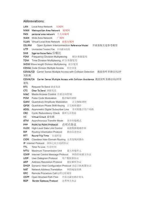
Abbreviations:LAN Local Area Network 局域网MAN Metropolitan Area Network 城域网PAN personal area network 个人局域网WAN Wide Area Network 广域网VLAN Virtual Local Area Network 虚拟局域网OSI/RM Open System Interconnection Reference Model开放系统互连参考模型UTP Unshielded Twisted Pair 非屏蔽双绞线SNR Sigal-to-Noise Ratio信噪比FDM Frequency Division Multiplexing 频分多路复用TDM Time Division Multiplexing 时分多路复用WDM Wave length Division Multiplexing波分复用CDMA Code Division Multiple Access 码分多址CSMA/CD Carrier Sense Multiple Access with Collision Detection 载波侦听多路访问/冲突检测CSMA/CA Carrier Sense Multiple Access with Collision Avoidance 载波侦听多路访问/冲突避免RTS Request To Send请求发送CTS Clear To Send 清除发送MAC Media Access Control 介质访问控制PCM Pulse Code Modulation 脉冲编码调制QAM Quadrature Amplitude Modulation 正交振幅调制QPSK Quadrature Phase Shift Keying 正交相移键控ADSL Asymmetric Digital Subscriber Line 非对称数字用户环路CRC Cyclic Redundancy Check 循环冗余校验VC Virtual Circuit 虚电路ATM Asynchronous Transfer Mode 异步传输模式PPP Point to Point Protocol 点对点协议HLDC High-Level Data Link Control 高级数据链路控制RIP Routing Information Protocol 路由信息协议RTT Round-Trip Time 往返时延CIDR Classless Inter-Domain Routing 无类别域间路由IP Internet Protocol 网络之间互连的协议TTL Time To Live 生存时间MTU Maximum Transmission Unit 最大传输单元ICMP Internet Control Message Protocol 网络控制报文协议UDP User Datagram Protocol 用户数据报协议ARP Address Resolution Protocol 地址解析协议DHCP Dynamic Host Configuration Protocol 动态主机配置协议NAT Network Address Translation 网络地址转换RPC Remote Procedure Call 远程过程调用OSPF Open Shortest Path First 开放式最短路径优先BGP Border Gateway Protocol 边界网关协议TCP Transmission Control Protocol 传输控制协议RTP Real-time Transpo rt P rotocol 实时传输协议FTP File Transfer Protocol 文件传输协议SMTP Simple Mail Transfer Protocol 简单邮件传输协议POP3 Post Office Protocol - Version 3 邮局协议版本3IAMP internet message access protocol 因特网信息报文存取协议?不知道对不对IMAP Internet Mail Access Protocol Internet邮件访问协议DNS Domain Name System 域名系统URL Uniform Resoure Locator 统一资源定位器HTTP Hyper Text Transfer Protocol 超文本传输协议WWW World Wide Web 万维网1、Basic and important concepts or notations●network architecture, layers, protocols●OSI/RM, TCP/IP reference model, main tasks of data link/network/transportlayers, protocols at each layer of TCP/IP model●PAN, LAN, WAN, VLAN, WLAN●bandwidth, link capacity●multiplexing, channel allocation●Frame, Ethernet frame format, MAC address●framing method:character-count, byte-stuffing, bit-stuffing, flag byte●Connection/connectionless service, circuit switching/packet switching,●Error Control coding, Hamming distance●Hamming code, even-parity /odd-parity●CRC, generator polynomial, remainder●stop-and-wait protocols, sliding window, go-back-n, selective-repeat, piggyback ●CSMA/CD●hidden station problem, exposed station problem, CSMA/CA●hub/repeater /switch/bridge/router/gateway.●routing algorithm, Distance vector routing, link state routing●IP address, classful and special addressing, CIDR, subnetting/aggregation,mask/prefix●routing table/forwarding,●packet, IPv4 header●NAT, 3 reserved private IP address ranges●TCP, port/port number, TCP header, three-way handshake●congestion control, ECN/RED, AIMD/slow start, congestion window, threshold●DNS system, domain name resolution2、Computations●Nyquist law, Shannon law, PCM●FDM, CDMA●bit-stuffing, byte-stuffing, character-count●Hamming code, CRC●CSMA/CD,minimal frame size●Distance vector routing algorithm●CIDR, aggregation●forwarding in routers, longest matching11 What is the principal difference between connectionless communication andconnection-oriented communication?Connection-oriented communication has three phases. In the establishment phase, a request is made to set up a connection. Only after this phase has been successfully completed can the data transfer phase be started and data transported. Then comes the release phase.Connectionless communication does not have these phases. It just sends the data.16 把比特流转化为帧OSI 数据链路层TCP/IP :链路层决定哪条路径通过子网OSI 网络层TCP/IP 互联网层20 What is the main difference between TCP and UDP.Answer:The first one, TCP (Transmission Control Protocol), is a reliableconnection-oriented protocol that allows a byte stream originating on one machine to be delivered without error on any other machine in the Internet.The second protocol, UDP (User Datagram Protocol), is an unreliable, connectionlessprotocol for applications that do not want TCP's sequencing or flow control and wish to provide their own.TCP是transmission control protocol传输控制协议,UDP是user data gram protocol用户数据电报协议。

51.What can a network administrator utilize by using PPP Layer 2 encapsulation? (Choose three.)A. VLAN supportB. compressionC. authenticationD. sliding windowsE. multilink supportF. quality of serviceAnswer: BCE解释一下:PPP协议是能支持认证的,包括PAP和CHAP;PPP还支持压缩功能和差错校验,还可实现多链路捆绑。
而他们的这些功能都是HDLC所没有的。
52.Refer to the exhibit. What is the meaning of the term dynamic as displayed in the output of the show frame-relay map command shown?A. The Serial0/0 interface is passing traffic.B. The DLCI 100 was dynamically allocated by the router.C. The Serial0/0 interface acquired the IP address of 172.16.3.1 from a DHCP server.D. The DLCI 100 will be dynamically changed as required to adapt to changes in the Frame Relay cloud.E. The mapping between DLCI 100 and the end station IP address 172.16.3.1 was learned through Inverse ARP.Answer: E解释一下:这是个关于MAP的知识。


多协议标记交换MPLS多协议标记交换xx?12?4MPLS/JYHxx1MPLS Multi?Protocol LabelSwitch?京邮电大学计算机科学与技术学院宽带网研究中心金跃辉主要内容xx?12?4MPLS/JYHxx2?MPLS基本思想?MPLS基本功能、工作原?、网络结构?MPLS核心技术?标记分配和标记交换技术、LDP、LSP?MPLS服务?显示?由、VPN、流?工程、QoSMPLSxx?12?4MPLS/JYHxx3提出的动机?Inter的高速发展和新业务的出现,对基于IP的承载网提出了挑战?各种IP与ATM融合的技术都无法全面解决现有问题,但这些IP交换解决方案都意识到将选?和交换结合起来的优势?当前的网络技术提供的VPN解决方案都存在缺陷,?能适应VPN市场的快速发展?网络向宽带化、智能化和一体化方向发展MPLSxx?12?4MPLS/JYHxx4标准化?IETF的MPLS工作组?主要目标是开发一个综合选?和交换的标准,把?由选择功能转移到网络边缘,把效率?高、结构?简单的交换功能放在核心网络中?可以运??同的链?层技术,如ATM、FR、PPP、POS、LAN等?实际上,网络层协议只限于IPv4和IPv6?ITU?T的SG11、SG13、SG15?MPLS ForumMPLSxx?12?4MPLS/JYHxx5IP ForwardingLABELSWITCHINGIP ForwardingIPIP#L1IP#L2IP#L3IP基本思想:边缘?由、核心交换MPLSMPLS/JYHxx6网络结构Label EdgeRoutersLabelSwitchingRouters(LSRsMPLSxx?12?4MPLS/JYHxx7术语?FEC:Forwarding EquivalenceClass?LSR:Label SwitchingRouter?LER:Label EdgeRouter?LDP:Label DistributionProtocol?LSP:Label SwitchedPath转发等价类xx?12?4MPLS/JYHxx8FEC(1)?在相同?径上转发,?由器以相同方式处?的一组IP分组,可以映射到同一标记?FEC可以?解为一系列属性的集合?常见的属性包括地址前缀、主机地址等?确定FEC的原则?分组具有相同的地址前缀、相同的主机地址或相同的QoS要求等转发等价类xx?12?4MPLS/JYHxx9分组去往的目的地?同,但可以映射到一条公共通?上IP1IP2IP1IP2LSRLSRLERLERLSPIP1#L1IP2#L1IP1#L2IP2#L2IP1#L3IP2#L3FEC (2)标记交换?由器xx?12?4MPLS/JYHxx10LSR(1)?Label SwitchingRouter?运?传统IP选?协议,完成?由控制功能,?新和维护?由表?运?MPLS控制协议,以与邻接设备协调FEC/标记的绑定信息,建立和维护标记转发表LIB,支持标记交换?可以利用传统交换机扩充IP选?;或将一个传统?由器升级支持MPLS标记交换?由器xx?12?4MPLS/JYHxx11LSR(2)?由协议(OSPF,BGP)标记信息库LIB应用接口TCP/IP?由表ATM等交换结构硬件转发接口数据转发单元标记交换?径LSP控制单元MPLS控制管?(LDP,RSVP等)标记边缘?由器xx?12?4MPLS/JYHxx12LER?Label EdgeRouter?完成连接MPLS域和非MPLS域以及?同MPLS域的功能?进?FEC划分,与内部MPLSLSR交换FEC/标记绑定信息?给分组加标记或剥去标记?也可用于确定业务类型,实现策略管?,接入流?工程控制等标记xx?12?4MPLS/JYHxx13?简短而长度固定的标识符,用于识别转发等价类FEC,将一个标记指派给一个FEC称为标记绑定(Binding)?只在本地有意义,经每一跳后标记是变化的,但经逻辑级联就构成LSP,类似于VPI/VCI构成PVC?标记的格式依赖于分组封装所在的介质,MPLS允许在LSP的?同部分使用?同的封装技术标记封装xx?12?4MPLS/JYHxx14LabelMPLSATM FREther PPPVPIVCI DLCI“Shim Label”L2“ShimLabel”…….IP|PAYLOADL3MPLS专用硬件/软件MPLSxx?12?4MPLS/JYHxx15标记格式Label(标记):20bitsEXP(实验字段):3bitsS(栈底指示符):1bitTTL(生存期字段):8bitsLabel EXPS TTLShimLabel共32bits标记堆栈xx?12?4MPLS/JYHxx16?分组可以携带多个标记,这些标记在分组中以堆栈的形式存在?标记堆栈的层数叫标记堆栈的”深度”,对标记堆栈的操作按照”后进先出”的原则进?;决定如何转发分组的标记始终是栈顶标记?当分组第一次进入MPLS域时,将标记插入分组头的操作为”标记入栈”;当分组离开MPLS域时,标记将被删除,称为”标记弹栈”?标记堆栈简化了标记交换?由器的运作,达到分层次选?的目的。
tunnel(GRE隧道)VPN配置过程分析Tunnel (GRE tunnel) VPN Configuration Process AnalysisIntroduction:Virtual Private Networks (VPNs) are widely used to establish secure and private connections over a public network, such as the internet. One common type of VPN is the tunnel (GRE tunnel) VPN, which utilizes Generic Routing Encapsulation (GRE) to encapsulate and transmit data packets between two remote networks. This article will analyze the configuration process of a tunnel VPN, focusing on the steps involved and the key considerations to ensure a successful setup.Configuration Process:1. Requirements analysis:Before starting the configuration process, it is crucial to determine the specific requirements of the VPN. This includes identifying the remote networks that need to be connected, the types of data to be transmitted, and any security measures that must be implemented.2. Network topology design:Based on the requirements analysis, a network topology design needs to be created. This design outlines the physical and logical layout of the network, including the placement and configuration of routers, firewalls, and VPN gateways.3. Selection of VPN gateways:In the case of tunnel VPNs, specific VPN gateways capable of supporting GRE tunneling must be selected. These gateways act as endpoints for the VPN connections, allowing data packets to be encapsulated and securely transmitted through the tunnel.4. Configuration of routers:The next step involves configuring the routers at both ends of the VPN connection. This includes assigning IP addresses to the router interfaces, enabling GRE tunneling, and setting up routing tables to ensure proper forwarding of data packets.5. GRE tunnel creation:Once the routers are configured, the GRE tunnels can be created. This involves specifying the source and destination IP addresses of the tunnel endpoints, as well as assigning a tunnel interface to facilitate the encapsulation and decapsulation of data packets.6. Encryption and authentication configuration:To enhance the security of the VPN connection, encryption and authentication mechanisms should be implemented. Popular protocols like IPsec can be utilized to encrypt the data traffic and establish secure communication between the remote networks.7. Testing and troubleshooting:After completing the configuration steps, it is crucial to test the VPN connection thoroughly. This includes verifying connectivity between the remote networks, testing data transmission, and ensuring that all securitymeasures are working as intended. If any issues are encountered, troubleshooting techniques should be employed to identify and resolve the problems.Key Considerations:1. Security:When configuring a tunnel VPN, it is essential to prioritize security. This includes selecting strong encryption algorithms, implementing authentication mechanisms, and regularly updating the VPN gateways and routers with the latest security patches.2. Scalability:The VPN design should be scalable to accommodate future growth and changes in network requirements. This can be achieved by using dynamic routing protocols, such as OSPF or BGP, which can dynamically adapt to network changes and optimize the routing process.3. Performance:Proper bandwidth planning and traffic prioritization should be considered to ensure optimal performance of the tunnel VPN. Analyzing the expected data volume and bandwidth requirements can help prevent congestion and maintain a high-quality connection.4. Redundancy:To minimize the risk of a single point of failure, redundancy measures, such as implementing redundant VPN gateways and routers, should beconsidered. This can help ensure continuous operation of the tunnel VPN, even in the event of hardware failures or network disruptions.Conclusion:Configuring a tunnel (GRE tunnel) VPN involves a systematic approach that includes requirements analysis, network topology design, selection of VPN gateways, router configuration, GRE tunnel creation, encryption and authentication configuration, as well as testing and troubleshooting. By considering key factors such as security, scalability, performance, and redundancy, a well-designed tunnel VPN can provide secure and reliable connectivity between remote networks.。
NC OR RE C T E DP RO OFAdding more intelligence to the network routing problem:AntNet and Ga-agentsS.Liang,A.N.Zincir-Heywood,M.I.Heywood *NIMS Group,Faculty of Computer Science,Dalhousie University,6050University Avenue,Halifax,NS,Canada B3H 1W5Received 12November 2003;received in revised form 4January 2005;accepted 10January 2005AbstractAntNet and GA-agent algorithms are benchmarked against a series of dynamic network routing problems.Performance is characterized using multiple performance metrics on the Japanese backbone (NTTNET).NTTNET is used on account of the elongated topology presenting a more challenging routing problem than in the case of the American backbone,which is basically square.The AntNet scheme is found to provide the best routing ability providing global information is available and network security is not a factor.The GA-agent algorithm is shown to provide routing performance between the AntNet algorithm with global information and that without,whilst avoiding global information requirements and satisfying typical models of network security.#2005Published by Elsevier B.V .Keywords:Insect metaphor;Genetic algorithms;Packet switched network routing;Decentralized problem solving1.IntroductionNetwork information systems and telecommunica-tion in general rely on a combination of routing strategies and protocols to ensure that information sent by a user is actually received at the desired remote location.In addition,the distributed nature of the problem means that multiple users can make requests simultaneously.This results in delayed responsetimes,lost information or other reductions to the quality of service objectives on which users judge network operation.Routing is the process used to determine how a packet travels from source to destination.Protocols are used to implement hand-shaking activities such as error checking and receiver acknowledgements.In this work,we are interested in the routing problem on computer networks.The routing problem has several properties,which make it particularly challenging.The problem is distributed in nature;hence,a solution that assumes access to any form of global information is not desirable.The problem is also dynamic;hence a solution that is sufficient for presently experienced network condi-tions may well be inefficient under other loads/locate/asoc*Corresponding author.Tel.:+19024942951;fax:+19024921517.E-mail addresses:abacus@cs.dal.ca (S.Liang),zincir@cs.dal.ca (A.N.Zincir-Heywood),mheywood@cs.dal.ca (M.I.Heywood).1568-4946/$–see front matter #2005Published by Elsevier B.V .doi:10.1016/j.asoc.2005.01.005NC OR RE C T E DP RO O Fexperienced by the network.Moreover,the traf fic experienced by networks is subject to widely varying load conditions,making ‘typical ’network conditions unrepresentative.Traditionally,routing strategies are implemented through the information contained in routing tables available at each node in the network [1].That is,the table consists of speci fic entries for the neighboring nodes and then a series of default paths for packets with any other destination,for example,OSPF or BGP4[2].Application of a classical optimization technique to such a problem might take the form of first assessing the overall pattern of network traf fic,and then de fining the contents of each routing table such that the measured congestion is minimized.This approach does not generally work in practice as it simply costs too much to collect the information centrally on a regular basis,where regular updating is necessary in order to satisfy the dynamic nature of network utilization.We,therefore,see the generic objectives of a routing strategy to be both real-time recon figurable and be based on locally available information,whilst also satisfying the user quality of service objectives (i.e.a global objective).Several approaches have been proposed for addressing these objectives including:active network-ing [3],social insect metaphors [4,5]cognitive packet networks [6],and what might be loosely called other ‘adaptive ’techniques (e.g.evolutionary computation [7,8],neural networks [9]).The latter typically involve using evolutionary or neural techniques to produce a ‘routing controller ’as opposed to a ‘routing table ’at each node,where the controller may require knowl-edge of the global connectivity to ensure a valid route.The global information assumption may be avoided by framing the problem in a reinforcement-learning context [9].However,the Q-learning method,on which this is based,results in single path solutions for each destination.Both the social insect metaphor and the cognitive packet approach provide a methodology for routing,without such constraints;by utilizing probabilistic routing tables and letting the packets themselves investigate and report network topology and performance.All methods as currently implemented,however,suffer from one drawback or another.Cognitive packet networks and active networking algorithms attempt to provide routing programs at the packet level,henceachieving scalable run time ef ficiency becomes an issue.Implementations of ‘adaptive ’techniques or social insect metaphors frequently rely on the avail-ability of global information [10].Finally,the very nature of the packet routing problem implies that performance should be measured from multiple perspectives simultaneously,where most results cur-rently available characterize performance using one or two parameters alone.The purpose of this work is,firstly,to investigate the application of a social insect metaphor to solve the dynamic routing problem.This is shown to rely on the availability of a priori global information.Secondly,a distributed genetic algorithm (GA)is introduced.This represents a major departure from previous works attempting to utilize GAs to solve the dynamic routing problem,e.g.[7,8].In particular,a methodology is detailed for solving the representation problem without recourse to global information.The system is bench-marked under dynamic and static network conditions from the perspective of multiple performance metrics.In the following,Section 2introduces the ‘ant ’based social insect metaphor scheme for packet routing against which this work is compared.Section 3introduces the proposed alternative scheme based on a distributed genetic algorithm.Results are presented in Section 4and conclusions are drawn in Section 5.2.AntNet social insect metaphoreAs indicated above,active networking [3]and cognitive packet [6]based approaches emphasize a per packet mechanism for routing.The aforementioned ‘adaptive ’techniques [7–9]tend to emphasize adding ‘intelligence ’to the routers leaving the packets unchanged.A social insect metaphor provides a middle ground in which the concepts of a routing table and data packet still exist,but in addition,intelligent packets —ants —are introduced thatinteract tokeep the contents of the routing tables up to date.To do so,the operation of ant packets is modeled on observations regarding the manner in which worker ants use chemical trails as a method of indirect stigmergic communication.Speci-fically,ants are only capable of simple stochastic decisions in fluenced by the availability of previously laid stigmergic trails.The chemical denoting a stigmergic trail is subject to decay over time,andS.Liang et al./Applied Soft Computing xxx (2005)xxx–xxx245464748495051525354555657585960616263646566676869707172737475767778798081828384858687888990919293949596979899100101102103104105106107108109110111112113114115116117118119120121122123124125126127128129130131132133134135136137NC OR RE C T E DP RO O Freinforcement proportional to the number of ants takingthe same path.Trail building is naturally a bi-directional process,ants need to reach the food (destination)and make a successful return path,in order to signi ficantly reinforce a stigmergic trail (forward only routing has also been demonstrated [5]).Moreover,the faster the route,then the earlier the trail is reinforced.An ant on encountering multiple stigmergic trails will probabil-istically choose the route with greatest stigmergic reinforcement.Naturally,this will correspond to the ‘fastest ’route to the food (destination).The probabil-istic nature of the decision,however,means that ants are still able to investigate routes with lower stigmergic reinforcement.This approach has proved to be a flexible framework for solving a range of problems including the traveling sales man problem [11]and the quadratic assignment problem [12].The work reported here follows the ‘AntNet ’algorithm of Di Caro and Dorigo,where this was previously demonstrated to perform better than typical approaches to the routing problem including OSPF (as currently employed on the Internet)[4].2.1.AntNet algorithmIt is assumed that routing tables,T k ,exist at each node,k ,in which a routing decision is made.Tables consist of ‘n ’rows,one row for each neighboring node/link.As far as a normal data packet is concerned,a route is selected based on the neighbor node probabilities.New forward ants,F sd ,are created periodically,but independently of the other nodes,from source,s ,to destination node,d ,in proportion to the destination frequency of passing data packets.Forward ants travel the network using the same priority structures as data packets,hence are subject to the same delay pro files;Next link in the forward ant route is selected stochastically,p _(j ),in proportion to the routing table probabilities and length of the corresponding output queue.p 0ðj Þ¼p ðj Þþa l j 1þa ðj N k j À1Þwhere p (j )is the probability of selecting node j asthe next hop;a weights the signi ficance given to local queue length verses global routing informa-tion,p (j );lj is proportional to the inverse of queue length at destination ‘j ’normalized to the unit interval;and N k is the number of links from node k ;On visiting a node different from the destination,a forward ant checks for a buffer with the same identi fier as itself.If such a buffer exists,the ant must be entering a cycle and dies.If this is not the case,then the ant saves the previously visited node identi fier and time stamp at which the ant was serviced by the current node in a buffer with the forward ant ’s identi fier.In this work,the total number of buffers at a node is managed by attaching an ‘‘age ’’to buffer space and allowing backward ants to free the corresponding buffer space.By introducing buffers at routers,it is no longer necessary to carry all node and duration information in the packet to the target duration as in the original model [4].Only the previous node information is,therefore,carried by each ant;When the current node is the destination,k =d ,then the forward ant is converted into a backward ant,B ds .The information recorded at the forward ant buffer is then used to retrace the route followed by the forward ant;At each node visited by the backward ant,routing table probabilities are updated using the following rule,IF (node was in the path of the ant)THEN p (i )=p (i )+r {l Àp (i )}ELSE p (i )=p (i )ÀrP (i )where r 2(0,1]is the reinforcement factor central to weight the relative signi ficance of path quality (length),congestion and underlying network dynam-ics.As indicated above,the reinforcement factor sh-ould be a factor of the trip time and the local stati-stical model of the node neighborhood.To this end [4]recommend the following relationship,r ¼c 1W bestt ant þc 2I sup ÀI inf ðI sup ÀI inf Þþðt ant ÀI inf Þwhere W best is the best case trip time to destination d over a suitable temporal horizon,W ;t ant is the actual trip time taken by the ant;I inf ¼W best ;I sup ¼m kd þf s kd =½W ð1Àg Þ 0:5g .S.Liang et al./Applied Soft Computing xxx (2005)xxx –xxx3138139140141142143144145146147148149150151152153154155156157158159160161162163164165166167168169170171172173174175176177178179180181182186187188189190191192193194195196197198199200201202203204205206207208209210211212213214215216217218219220221222223224225226227228229230231232233234235236237238NC OR RE C T E DP RO O FThe estimates for mean,m kd ,and variant,s kd ,of the trip time are also made iteratively,using the trip time information,o kd .Thus,m kd ¼m kd þh ðo kd Àm kd Þðs kd Þ2¼ðs kd Þ2þh fðo kd Àm d Þ2Àðs kd Þ2gThus,trip time information is updated incrementally based on the recorded trip duration between current node,k ,and ultimate destination,d .2.2.Global information assumptionAlthough providing for a robust ant routing algorithm under simulated conditions [4],an assump-tion is made,which inadvertently implies the use of global information —knowledge of the number of nodes in the network [10].The de finition of routing tables assumes that every node has a unique location in the routing table or a total of l (number of neighboring nodes)by n (number of nodes in the entire network)entries.Hereafter,this is referred to as the GlobalAnt algorithm.In practice,this is never the case.To do so would assume that it is first feasible,and secondly,should the network con figuration ever change,then all nodes should be updated with the new con figuration information.In order to avoid the use of global information,we consider the case of routing tables limited to detailing actions in terms of the neighboring nodes alone,or a total of 2by l entries.Hereafter referred to as the LocalAnt algorithm.This is equivalent to the tables as used by OSPF or BGP4protocols currently in use [2].Such a limitation,therefore,places greater emphasis on the learning capacity of the ant.In Section 4,the AntNet algorithm is benchmarked under both local (LocalAnt)and global (GlobalAnt)routing table con figurations.3.Genetic algorithm modelGenetic algorithms (GA)are a class of generic search algorithms that perform a parallel search over a fixed ‘‘population ’’of candidate solutions.To do so,Darwin ’s concept of survival of the fittest and observations from genetics are used to guide the general mode of operation.Speci fically,a selection operator provides the pressure to improve the contentsof the population,examples being generational or tournament based selection.Search operators (cross-over and mutation)address the exploitation-explora-tion trade off associated with manipulating individual members of the population.The algorithm as a whole is iterative in nature with individuals being repeatedly modi fied such that the overall fitness of the population improves (Holland ’s Schema Theorem [13]).There are three principle inter-related design decisions that have a signi ficant impact on the ability of a GA to ef ficiently solve problems.Firstly,the representation problem,which is how to ef ficiently encode candidate solutions into the genotypic string format of a GA.Secondly,the operator problem,or how to de fine operators such that individuals are always syntactically correct.The third problem is how to succinctly express fitness such that the ‘best ’individuals of the population solve all the properties of the problem of interest.In the case of this work,we desire a representation that is independent of network connectivity —unlike,for example,the approach of Munetomo [7].The operator problem naturally has two parts —selection and search.The de finition of suitable search operators is rendered straightforward (standard crossover and mutation operators are applicable)if we are able to pose suitable solutions to the representation problem.The case of a suitable selection operator for this work is addressed by utilizing the concept of a static subpopulation model with migration.That is to say,each node of the network has an independent population of candidate solutions and best case solutions are allowed to periodically migrate between neighboring nodes,as in an island model of evolution [14].Given these general observations,the following subsections detail the speci fic methodology employed and hereafter referred to as GA-agents.3.1.Basic GA-agentsLetting individuals from each population travel the network address the objectives of the representation problem.Thus,the genotypic content of any individual expresses the number of nodes visited and routing decision taken at each node.This is similar to the concept of the forward ant in the AntNet algorithm.Likewise,as each ‘GA-agent ’travels the network,previous hop and elapsed time information isS.Liang et al./Applied Soft Computing xxx (2005)xxx –xxx4236237238239240241242243244245246247248249250251252253254255256257258259260261262263264265266267268269270271272273274275276277278279280281282283284285286287288289290291292293294295296297298299300301302303304305306307308309310311312313314315316317318319320321322323NC OR RE C T E DP RO O Frecorded (Fig.1).On reaching the node identi fied by the last gene,the individual becomes a backward ant and merely retraces its path and waits at the corresponding source node for fitness evaluation (routing table updates are only performed at the source node)(Fig.1).In the special case of a GA-agent attempting to return down the same link with which the node was entered,the router randomly selects the next hop from the available links,and changes the gene to the new value (deterministic mutation).If no next hop is available,then the chromosome is truncated,and the GA-agent becomes a backward agent (Fig.1).A genotype,therefore,takes the form of a list of integers —representing next hop offsets,e.g.{1,5,0,4,2,3,5}—over the interval [0,L ],where ‘Z ’is selected to enable indexing of node connectivity.1On entering a node,a gene (offset)is used to identify the next link using a clockwise count from the link that the GA-agent entered the node,i.e.the next link isselected modulo (gene %#of links).Such a representation is then independent of the speci fic network connectivity and directly supports single point crossover,resulting in variable length indivi-duals.Mutation randomly selects a gene and adds/subtracts an integer such that the new gene is still in the interval [0,L ].Selection takes the form of a steady-state tourna-ment of size 4.Thus,when four GA-agents return to the same source node,they are ranked in accordance with their fitness,the worst two GA-agents being replaced by the children of the best (Fig.2).The fitness function itself incorporates the popularity of nodes visited as well as the time taken to reach nodes encountered by GA-agents.Both of these properties are measured with respect to the original source node.Popularity of destination ‘i ’at node ‘k ’(NP k (i ))is a dynamic property,measured at the original source node by recoding the frequency of different data packet destinations as seen by the source node over a fixed time window (the time window is set 50s in this work),NP k ði Þ¼Dest ði ÞTD kS.Liang et al./Applied Soft Computing xxx (2005)xxx –xxx5324325326327328329330331332333334335336337338339340341342343344345346347348349350351352353354355356357358359360361362363Fig.2.Routing and population update.1In all the experiments of Section 5,‘Z ,’is set to 6.NC OR RE C T E DP RO O Fwhere TD k is the total number of data packets passing through node ‘k ’;and Dest(i )is the number of data packets with destination ‘i ’.Fitness now takes the form,PNP k ði ÞÂtrip Àtime i Ptrip Àtime i Thus,GA-agents that find shortest paths to frequently used destinations are favored.The routing table in the GA approach consists of a list of returned agents,every entry corresponds to an evaluated returned agent path.On routing a data packet,the router checks the table for a path that had experienced shortest trip time to the desired destina-tion (Table 1,column 3);if such an entry is not found,the entry with the highest fitness (Table 1,column 2)will be selected as the default next node for this data packet (Fig.3).The first two columns in the routing table are used during ranking and replacement of winning chromosomes (Fig.2).3.2.Aging and population initializationAs indicated in the introduction,the general packet switched routing problem of interest here has dynamic properties as a result of different load conditions or network outages.This means that the routing strategy must be able to continuously adapt to new conditions.To provide such a property an incremental aging penalty is applied to each GA-agent entry of the routing table.Thus,fitness is decreased and trip times increased at each update to the routing table entries (Fig.2).In addition,each node of the network may naturally have a different degree of connectivity;hence pose a more (less)signi ficant routing problem.Populations (at each node)are,therefore,initialized in proportion to the degree of connectivity of each node;where asquare law was empirically found to provide suf ficient search capacity (Fig.4).4.EvaluationFor the purposes of investigation and comparison,a discrete event simulation (DES)is developed (C++,UNIX system)for modeling the action of the GA-agent and AntNet algorithms on a network con figured to represent the Japanese backbone (NTTNET)(Fig.5).Such a con figuration is of particular interest due to the long thin topology in comparison to other networks (e.g.in the box like topology of the USS.Liang et al./Applied Soft Computing xxx (2005)xxx –xxx6364365366367368369370371372373374375376377378379380381382383384385386387388389390391392393394395396397398399400401401402403404405406407408409410411Table 1Example GA-agent routing tableAgent ID Fitness Trip time (ms)and node ID 950.32(3,J),(9,C)(21,W)2340.355(1,B),(7,A),...,(432,Y).........310.71(5,C),(9,K),...,(871,X)Fig.5.Japanese NNTNET topology.NC OR RE C T E DP RO O Fbackbone nodes tend to provide a high degree of connectivity across the network as a whole).This property of NTTNET makes it more dif ficult to identify alternative routes or increases the number of pathologically bad routes.The DES models each node as an incoming buffer,a memory space for processing packets,and an outgoing buffer for each neighboring link.Both AntNet and GA-agent algorithms are simulated under the same environmental conditions.That is,an event generator is used to generate the events,such as new packet time of generation,or router availability.The following are the parameters used in the simulation,Network topology takes the form of the Japanese backbone (Fig.5);Forward ants are launched every 300ms;Data packets are generated by Poisson distribution (mean of 35ms);AntNet and GA-agent algorithms are given 5s at the beginning of the simulation to converge the initial routing tables.During this period,routing packets (ants or GA-agents)are the only packets traversing the network;Any packets that are routed down links representing a fault condition are distinguished as lost packets.In addition,packets may also be killed .In this case any packets,including data packets,are terminated should they encounter a previously visited node.Given the probabilistic nature of the routing tables this represents a rather harsh constraint,but is utilized to emphasize the properties of different routing strategies.In the following results,lost and killed packets are collectively referred to as dead packets.Simulations are ran for the duration of 1250s,as a result 1,985,536data packets are generated.The queue length is the total number of waiting packets per se-S.Liang et al./Applied Soft Computing xxx (2005)xxx –xxx7412413414415416417418419420421422423424425426427428429430431434435436437438439440441442443444445446447448449450451452453454Table 2Parameter values AntNet GA-agent a 0.3P (crossover)0.9c 10.7P (mutation)0.1c 20.3#Agents/link 232h 0.005Aging rate 0.9g0.654Prop.ratio (%)3Prop.freq.(ms)500Flow clear freq.(s)50Table 3Static parameters —scenario 1AlgorithmGA-agent GlobalAnt LocalAnt Finish time (s)125212531267Routing packets (%)481011Arrived packets (%)85.399.745.5Dead packets (%)14.70.354.5AP avg.trip time (ms)1171566398Fig.6.Throughput (bytes)vs.time (s)—no network failure.NC OR RE C T E DP RO O Fcond,which includes the data packets and the routing packets.In this paper,the routing packets refer to the ants in the AntNet algorithm,and to the GA-agents in the GA approach.4.1.Algorithm parameterizationParameter selection in the case of the AntNet algorithm follows the recommendations of Di Caro and Dorigo [4].Two versions of the AntNet algorithm are considered.LocalAnt represents the case of a routing table without the capacity to represent global information [10],whereas GlobalAnt represents the original ‘‘full ’’routing table scenarios [4].In the case of GA-agents,there are five basic parameters,summarized as follows1.Rates of crossover and mutation;2.#Agents/link 2—a constant c 1,which determines the population of chromosomes on every node;3.Aging —a constant c 22(0.0,1.0),rate by which fitness of individuals currently populating the routing tables decay;4.Propagate ratio —the number of chromosomes exchanged between populations,expressed as a %node population size;5.Propagate freq —constant rate/frequency of exchange of chromosomes between populations;6.Flow clear freq —a constant c 3,time interval over which data packet destination statistics are collected.Default values for GA-agent were established in [15].Table 2summarizes parameter values employed in the following experiments for both AntNet and GA-agents.work scenariosA total of four simulation scenarios are considered for the AntNet and GA approaches,all of which utilize the Japanese backbone network topology (Fig.5).Moreover,unlike the original study,we concentrate on network recon figuration properties [4].In the first case,all routers remain available,scenario 1.The remaining experiments investigate plasticity of the agents by introducing fault conditions.First,routerS.Liang et al./Applied Soft Computing xxx (2005)xxx –xxx8455456457458459460461462463464465466467468469470471472473474475476477478479480481487488489490491492493494495496497498499500501502503504Fig.7.Queue length vs.time (s)—no network failure.Table 4Static parameters —scenario 2AlgorithmGA-agent GlobalAnt LocalAnt Finish time (s)150716681369Routing packets (%)58.91011Arrived packets (%)70.692.341Dead packets (%)29.47.759AP avg.trip time (ms)3569982899NC OR RE C T E DP RO O FR34is removed at a time step of 500s,scenario 2,where this effectively cuts the network in two,with only one path linking the two halves.In scenario 3,two routers (R49,R13)are removed,whereas in scenario 4,the same two routers (R49,R13)are taken down asynchronously,but return later synchronously.Scenario 4is,therefore,of particular interest because it requires three different recon figurations —once in the introduction of each fault and again when all the faults are restored.In all cases the performance of routing algorithms is measured from multiple perspectives,S.Liang et al./Applied Soft Computing xxx (2005)xxx –xxx9505506507508509510511512513514515516517Fig.8.Throughput (bytes)vs.time (s)—node 34lost at 500s.Fig.9.Queue length vs.time (s)—node 34lost at 500s.。
accwiz.exe > 辅助工具向导acsetups.exe > ACS setup DCOM server executable actmovie.exe > 直接显示安装工具append.exe > 允许程序打开制定目录中的数据arp.exe > 显示和更改计算机的IP与硬件物理地址的对应列表at.exe > 计划运行任务atmadm.exe > 调用管理器统计attrib.exe > 显示和更改文件和文件夹属性autochk.exe > 检测修复文件系统autoconv.exe > 在启动过程中自动转化系统autofmt.exe > 在启动过程中格式化进程autolfn.exe > 使用长文件名格式bootok.exe > Boot acceptance application for registry bootvrfy.exe > 通报启动成功cacls.exe > 显示和编辑ACLcalc.exe > 计算器cdplayer.exe > CD播放器change.exe > 与终端服务器相关的查询charmap.exe > 字符映射表chglogon.exe > 启动或停用会话记录chgport.exe > 改变端口(终端服务)chgusr.exe > 改变用户(终端服务)chkdsk.exe > 磁盘检测程序chkntfs.exe > 磁盘检测程序cidaemon.exe > 组成Ci文档服务cipher.exe > 在NTFS上显示或改变加密的文件或目录cisvc.exe > 索引内容ckcnv.exe > 变换Cookiecleanmgr.exe > 磁盘清理cliconfg.exe > SQL客户网络工具clipbrd.exe > 剪贴簿查看器clipsrv.exe > 运行Clipboard服务clspack.exe > 建立系统文件列表清单cluster.exe > 显示域的集群_cmd_.exe > 没什么好说的!cmdl32.exe > 自动下载连接管理cmmgr32.exe > 连接管理器cmmon32.exe > 连接管理器监视cmstp.exe > 连接管理器配置文件安装程序comclust.exe > 集群comp.exe > 比较两个文件和文件集的内容*compact.exe > 显示或改变NTFS分区上文件的压缩状态conime.exe > IME控制台control.exe > 控制面板convert.exe > 转换文件系统到NTFSconvlog.exe > 转换IIS日志文件格式到NCSA格式cprofile.exe > 转换显示模式cscript.exe > 较本宿主版本csrss.exe > 客户服务器Runtime进程csvde.exe > 日至格式转换程序dbgtrace.exe > 和Terminal Server相关dcomcnfg.exe > DCOM配置属性dcphelp.exe > ?dcpromo.exe > AD安装向导ddeshare.exe > DDE共享ddmprxy.exe >debug.exe > 就是DEBUG啦!dfrgfat.exe > FAT分区磁盘碎片整理程序dfrgntfs.exe > NTFS分区磁盘碎片整理程序dfs_cmd_.exe > 配置一个DFS树dfsinit.exe > 分布式文件系统初始化dfssvc.exe > 分布式文件系统服务器diantz.exe > 制作CAB文件diskperf.exe > 磁盘性能计数器dllhost.exe > 所有COM+应用软件的主进程dllhst3g.exe >dmadmin.exe > 磁盘管理服务dmremote.exe > 磁盘管理服务的一部分dns.exe > DNS Applications DNSdoskey.exe > 命令行创建宏dosx.exe > DOS扩展dplaysvr.exe > 直接运行帮助drwatson.exe > 华生医生错误检测drwtsn32.exe > 华生医生显示和配置管理dtcsetup.exe > Installs MDTCdvdplay.exe > DVD播放dxdiag.exe > Direct-X诊断工具edlin.exe > 命令行的文本编辑器(历史悠久啊!)edlin.exe > 命令行的文本编辑器(历史悠久啊!)esentutl.exe > MS数据库工具eudcedit.exe > Type造字程序eventvwr.exe > 事件查看器evnt_cmd_.exe > Event to trap translator; Configuration tool evntwin.exe > Event to trap translator setupexe2bin.exe > 转换EXE文件到二进制expand.exe > 解压缩extrac32.exe > 解CAB工具fastopen.exe > 快速访问在内存中的硬盘文件faxcover.exe > 传真封面编辑faxqueue.exe > 显示传真队列faxsend.exe > 发送传真向导faxsvc.exe > 启动传真服务fc.exe > 比较两个文件的不同find.exe > 查找文件中的文本行findstr.exe > 查找文件中的行finger.exe > 一个用户并显示出统计结果fixmapi.exe > 修复MAPI文件flattemp.exe > 允许或者禁用临时文件目录fontview.exe > 显示字体文件中的字体forcedos.exe > Forces a file to start in dos mode. 强制文件在DOS模式下运行freecell.exe > Popular Windows Game 空当接龙ftp.exe > File Transfer Protocol used to transfer files over a network connection 就是FTP了gdi.exe > Graphic Device Interface 图形界面驱动grovel.exe >grpconv.exe > Program Manager Group Convertor 转换程序管理员组help.exe > displays help for Windows 2000 commands 显示帮助hostname.exe > Display hostname for machine. 显示机器的Hostnameie4uinit.exe > IE5 User Install tool IE5用户安装工具ieshwiz.exe > Customize folder wizard 自定义文件夹向导iexpress.exe > Create and setup packages for install 穿件安装包iisreset.exe > Restart IIS Admin Service 重启IIS服务internat.exe > Keyboard Language Indicator Applet 键盘语言指示器ipconfig.exe > Windows 2000 IP configuration. 察看IP配置ipsecmon.exe > IP Security Monitor IP安全监视器ipxroute.exe > IPX Routing and Source Routing Control Program IPX路由和源路由控制程序irftp.exe > Setup FTP for wireless communication 无线连接ismserv.exe > Intersite messaging Service 安装或者删除Service Control Manager中的服务jdbgmgr.exe > Microsoft debugger for java 4 Java4的调试器jetconv.exe > Convert a Jet Engine Database 转换Jet Engine数据库jetpack.exe > Compact Jet Database. 压缩Jet数据库jview.exe > Command-line loader for Java Java的命令行装载者krnl386.exe > Core Component for Windows 2000 2000的核心组件label.exe > Change label for drives 改变驱动器的卷标lcwiz.exe > License Compliance Wizard for local or remote systems. 许可证符合向导ldifde.exe > LDIF cmd line manager LDIF目录交换命令行管理licmgr.exe > Terminal Server License Manager 终端服务许可协议管理lights.exe > display connection status lights 显示连接状况llsmgr.exe > Windows 2000 License Manager 2000许可协议管理llssrv.exe > Start the license Server 启动许可协议服务器lnkstub.exe >locator.exe > RPC Locator 远程定位lodctr.exe > Load perfmon counters 调用性能计数logoff.exe > Log current user off. 注销用户lpq.exe > Displays status of a remote LPD queue 显示远端的LPD打印队列的状态,显示被送到基于Unix的服务器的打印任务lpr.exe > Send a print job to a network printer. 重定向打印任务到网络中的打印机。
Below you will find the assessment items as presented on the exam as well as the scoring rules associated with the item.Cisco Networking Academy content is copyrighted and the unauthorized posting, distribution or sharing of this exam content is prohibited.Close WindowAssessment SystemExam Viewer - ERouting Practice Final Exam - CCNA Exploration: 路由协议和概念 (Version 4.0)1What are two functions of a router? (Choose two.) gf e d c It connects multiple IP networks. gf e d c It controls the flow of data via the use of Layer 2 addresses.g fe d c It determines the best path to send packets. g fe d c It manages the VLAN database. g fe d c It increases the size of the broadcast domain.ObservableDescriptionMax Value1correctness of responseOption 1 and Option 3 are correct.1 point for each correct option.0 points if more options are selected than required.22When a router boots, what is the default order to locate the Cisco IOS if there is no boot system command? nm l k j ROM, TFTP server, flash n ml k j flash, TFTP server, ROM n ml k j flash, NVRAM, TFTP server nm l k j NVRAM, TFTP server, flashObservableDescriptionMax Value1correctness of response2 points for Option 20 points for any other option23Which router component is used to store the routing table? nm l k j Flash n m l k j NVRAM n ml k j ROM n ml k j SDRAMObservableDescriptionMax Value1correctness of response2 points for Option 40 points for any other option24Refer to the exhibit. How many routes are child routes? nm l k j 1 n m l k j 3 n ml k j 4 n ml k j 6ObservableDescriptionMax Value1correctness of response2 points for Option 30 points for any other option25Refer to the exhibit. Which statement is true concerning the routing configuration?nm l k j Using dynamic routing instead of static routing would have required fewer configuration steps. n ml k j The 10.1.1.0/24 and 10.1.2.0/24 routes have adjacent boundaries and should be summarized. n ml k j Packets routed to the R2 Fast Ethernet interface require two routing table lookups. nm l k j The static route will not work correctly.ObservableDescriptionMax Value1correctness of response2 points for Option 30 points for any other option26Refer to the exhibit. The network administrator issues the command no ip classless on Router1. What forward on a packet that is received by Router1 and is destined for host 192.168.0.26? nm l k j The packet will be dropped. n ml k j The packet will be forwarded to the gateway of last resort. n ml k j The packet will match the 192.168.0.0 network and be forwarded out Serial 0/0. n ml k j The packet will most closely match the 192.168.0.8 subnet and be forwarded out Serial 0/1.ObservableDescriptionMax Value1correctness of response2 points for Option 10 points for any other option27Refer to the exhibit. Routers R1 and R3 use different routing protocols with default administrative distance valu properly configured and the destination network is advertised by both protocols.Which path will be used to transmit the data packets between PC1 and PC2? nm l k j The packets will travel via R2-R1. n ml k j The packets will travel via R2-R3. nm l k j The traffic will be load-balanced between two paths — via R2-R1 and via R2-R3. n ml k j The packets will travel via R2-R3, and the other path via R2-R1 will be retained as the backup path.ObservableDescriptionMax Value1correctness of response2 points for Option 10 points for any other option28Refer to the exhibit. Router R1 is configured as shown in the exhibit. PC1 on 172.16.1.0/24 network can reach R1. The rest of the routers are configured with the correct IP addresses on the interfaces. Routers R2 and R3 d dynamic routing enabled. How far will PC1 be able to successfully ping? nml k j router R1 Fa0/0 interface n ml k j router R1 S0/0/0 interface n ml k j router R2 S0/0/0 interface n ml k j router R2 Fa0/0 and S0/0/1 interfaces n ml k j router R3 Fa0/0 and S0/0/0 interfacesObservableDescriptionMax Value1correctness of response2 points for Option 20 points for any other option29Refer to the exhibit. All routers are properly configured to use the EIGRP routing protocol with default settings, converged. Which statement correctly describes the path that the traffic will use from the 10.1.1.0/24 network to network?nm l k j It will use the A-D path only. n ml k j It will use the path A-D, and the paths A-C-D and A-B-D will be retained as the backup paths. It will use all the paths equally in a round-robin fashion.ml j The traffic will be load-balanced between A-B-D and A-C-D.ObservableDescriptionMax Value1correctness of response2 points for Option 40 points for any other option210Which two statements are true regarding link-state routing protocols? (Choose two.)f e c They are aware of the complete network topology. fe c They offer rapid convergence times in large networks. fe c They do not include subnet masks in their routing updates. fe c They rely on decreasing hop counts to determine the best path. fe c They do not work well in networks that require special hierarchical designs. fe c They pass their entire routing tables to their directly connected neighbors only.ObservableDescriptionMax Value1correctness of responseOption 1 and Option 2 are correct.1 point for each correct option.0 points if more options are selected than required.211Refer to the exhibit. R1 knows two routes, Path A and Path B, to the Ethernet network attached to R3. R1 learn 10.2.0.0/16 from a static route and Path B to network 10.2.0.0/16 from EIGRP. Which route will R1 install in its nm l k j Both routes are installed and load balancing occurs across both paths. nm l k j The route via Path B is installed because the EIGRP route has the best metric to network 10.2.0.0/16. n ml k j The route via Path A is installed because the static route has the best metric to network 10.2.0.0/16. n ml k j The route via Path B is installed because the EIGRP route has the lowest administrative distance to networ n ml k j The route via Path A is installed because the static route has the lowest administrative distance to networkObservableDescriptionMax Value1correctness of response2 points for Option 50 points for any other option212What two routing protocols use a hierarchal network topology? (Choose two.)gf e d c IS-ISg f e d c EIGRP g f e d c OSPF g fe d c RIPv1 g fe d c RIPv2ObservableDescriptionMax Value1correctness of responseOption 1 and Option 3 are correct. 1 point for each correct option.0 points if more options are selected than required.213Refer to the exhibit. Based on the output from the show running-config and debug ip rip commands, what a are added to the routing table of R1? (Choose two.)gf e d c R 192.168.1.0/24 [120/1] via 172.16.2.1, 00:00:24, Serial0/0/1g fe d c R 192.168.100.0/24 [120/1] via 172.16.1.1, 00:00:24, Serial0/0/0 g fe d c S 192.168.1.0/24 [1/0] via FastEthernet0/0 gf e d c R 192.168.9.0/24 [120/1] via 172.16.2.1, 00:00:24, Serial0/0/0g fe d c R 192.168.2.0/24 [120/1] via 172.16.1.2, 00:00:24, Serial0/0/0ObservableDescriptionMax Value1correctness of responseOption 2 and Option 3 are correct.1 point for each correct option.0 points if more options are selected than required.214Refer to the exhibit. The network has three connected routers: R1, R2 and R3. The routes of all three routers a be verified from the output?m l j ml j The IP address of the S0/0/0 interface of R1 is 10.1.1.2. ml j The IP address of the S0/0/1 interface of R2 is 10.3.3.2. m l j R2 is connected to the S0/0/1 interface of R3.ObservableDescriptionMax Value1correctness of response2 points for Option 40 points for any other option215Refer to the exhibit. All router interfaces are configured with an IP address and are operational. If no routing pro configured, what information will be included in the show ip route command output for router A? nm l k j All of the 192.168.x.0 networks will be in the routing table. n ml k j Routes to networks 192.168.1.0/24, 192.168.2.0/24, and 192.168.3.0/24 will be in the routing table. n ml k j The routing table will be empty because routes and dynamic routes have not been configured. n ml k j A default route is automatically installed in the routing table to allow connectivity between the networks.ObservableDescriptionMax Value1correctness of response2 points for Option 20 points for any other option216Refer to the exhibit. A network administrator is accessing router R1 from the console port. Once the administra router, which password should the administrator enter at the R1> prompt to access the privileged EXEC mode?nm l k j Cisco001 n ml k j Cisco123 n ml k j Cisco789 n ml k j Cisco901ObservableDescriptionMax Value1correctness of response2 points for Option 30 points for any other option217Which of the following could describe the devices labeled "?" in the graphic? (Choose three.) gf ed c DCE g fe d c CSU/DSU gf e d c LAN switchg fe d c modem g fe d c hubObservableDescriptionMax Value1correctness of responseOption 1, Option 2, and Option 4 are correct.1 point for each correct option.0 points if more options are selected than required.318Refer to the exhibit. Which router is advertising subnet 172.16.1.32/28? nm l k j Router1 n m l k j Router2 n ml k j Router3 n ml k j Router4ObservableDescriptionMax Value1correctness of response2 points for Option 40 points for any other option219Refer to the exhibit. The show cdp neighbors command was run at R1. Which two facts about the newly dete determined from the output? (Choose two.) gf e d c ABCD is a router that is connected to R1.f e c The device is connected at the Serial0/0/1 interface of R1.f e c R1 is connected at the S0/0/1 interface of device ABCD.f e c ABCD does not support switching capability.Observable Description Max Value1correctness of response Option 1 and Option 3 are correct.1 point for each correct option.0 points if more options are selected than required.220 A static route has been configured on a router. However, the destination network no longer exists. What shouldremove the static route from the routing table?m l j Change the routing metric for that route.m l j Nothing. The static route will go away on its own.m l j Change the administrative distance for that route.m l j Remove the route using the no ip route command.Observable Description Max Value1correctness of response 2 points for Option 40 points for any other option221Refer to the exhibit. A ping between host A and host B is successful, but pings from host A to operational hosts is the reason for this problem?n m l k j The FastEthernet interface of R1 is disabled.n m l k j One of the default routes is configured incorrectly.n m l k j A routing protocol is not configured on both routers.n m l k j The default gateway has not been configured on host A.Observable Description Max Value1correctness of response 2 points for Option 20 points for any other option222Refer to the exhibit. The network has three connected routers: R1, R2, and R3. The routes of all three routers a are operational and pings are not blocked on this network.Which ping will fail?n m l k j from R1 to 172.16.1.1n m l k j from R1 to 192.168.3.1n m l k j from R2 to 192.168.1.1n m l k j from R2 to 192.168.3.1Observable Description Max Value1correctness of response 2 points for Option 20 points for any other option223Refer to the exhibit. What action will R2 take for a packet that is destined for 192.168.2.0?n m l k j It will drop the packet.n m l k j It will forward the packet via the S0/0/0 interface.n m l k j It will forward the packet via the Fa0/0 interface.n m l k j It will forward the packet to R1.Observable Description Max Value1correctness of response2 points for Option 40 points for any other option224Refer to the exhibit. The users on the local network 172.16.1.0/24 complain that they are unable to connect to t should be taken to remedy the problem?nm l k j A new static route must be configured on R1 with the R3 serial interface as the next hop. n ml k j A new default route must be configured on R1 with the R3 serial interface as the next hop. nm l k j The default route on R2 should be configured with the R3 serial interface as the next hop. n ml k j The default route on R2 must be replaced with a new static route and the next hop should be the R1 FastEObservableDescriptionMax Value1correctness of response2 points for Option 30 points for any other option225Refer to the exhibit. What summary address can Router2 advertise to Router1 to reach the three networks on R without advertising any public address space or overlapping the networks on Router1? nm l k j 172.16.0.0/8 nm l k j 172.16.0.0/10 n ml k j 172.16.0.0/13 n ml k j 172.16.0.0/20ObservableDescriptionMax Value1correctness of response2 points for Option 30 points for any other option226Refer to the exhibit. Host A is unable to access the Internet, and troubleshooting has revealed that this is due t What is incorrectly configured in this network? nm l k j the IP address of the Fa0/0 interface of R1 n ml k j the subnet mask of the S0/0/0 interface of R1 n ml k j the IP address of the S0/0/0 interface of R1 nm l k j the subnet mask of the S0/0/0 interface of R2ObservableDescriptionMax Value1correctness of response2 points for Option 30 points for any other option227Refer to the exhibit. A new PC was deployed in the Sales network. It was given the host address of 192.168.10gateway of 192.168.10.17. The PC is not communicating with the network properly. What is the cause? nm l k j The default gateway is incorrect. n ml k j The address is in the wrong subnet. nm l k j The host address and default gateway are swapped. n ml k j 192.168.10.31 is the broadcast address for this subnet.ObservableDescriptionMax Value1correctness of response2 points for Option 40 points for any other option228Refer to the exhibit. The network administrator is planning IP addressing of a new network. What part of this ad be changed to allow communication between host A and the server?n m l k j the IP address of the servern m l k j the default gateway of host An m l k j the IP address of host An m l k j the default gateway of the serverObservable Description Max Value1correctness of response 2 points for Option 10 points for any other option229Which network design feature requires the deployment of a classless routing protocol?n m l k j private IP addressingn m l k j advertising default routesn m l k j variable length subnet masksn m l k j summarization on major network boundariesObservable Description Max Value1correctness of response 2 points for Option 30 points for any other option230 A network administrator needs to assign the very last usable IP address in the 172.24.64.0/18 network range toserves this LAN. Which IP address should the administrator configure on the interface?n m l k j172.16.128.154/18n m l k j172.16.255.254/18n m l k j172.24.64.254/18n m l k j172.24.127.254/18Observable Description Max Value1correctness of response 2 points for Option 40 points for any other option231Refer to the exhibit. All routers are running RIPv1. The two networks 10.1.1.0/29 and 10.1.1.16/29 are unable t What can be the cause of this problem?nm l k j Because RIPv1 is a classless protocol, it does not support this access. n ml k j RIPv1 does not support discontiguous networks. nm l k j RIPv1 does not support load balancing. n ml k j RIPv1 does not support automatic summarization.ObservableDescriptionMax Value1correctness of response2 points for Option 20 points for any other option232Refer to the exhibit. What information can be determined from the highlighted output? nm l k j R1 is originating the route 172.30.200.32/28. n ml k j Automatic summarization is disabled. nm l k j The 172.30.200.16/28 network is one hop away from R1. n ml k j A classful routing protocol is being used.ObservableDescriptionMax Value1correctness of response2 points for Option 20 points for any other option233What does RIP use to reduce convergence time in a larger network?ml j It reduces the update timer to 15 seconds if there are more than 10 routes. ml j It uses triggered updates to announce network changes if they happen in between the periodic updates. ml j It uses random pings to detect if a pathway is down and therefore is preemptive on finding networks that arObservableDescriptionMax Value1correctness of response2 points for Option 30 points for any other option234A network administrator has enabled RIP on routersB andC in the network diagram. Which of the following co updates from being sent to Router A? nm l k j A(config)# router rip A(config-router)# passive-interface S0/0nm l k j B(config)# router rip B(config-router)# network 192.168.25.48 B(config-router)# network 192.168.25.64 nm l k j A(config)# router rip A(config-router)# no network 192.168.25.32nm l k j B(config)# router rip B(config-router)# passive-interface S0/0nm l k j A(config)# no router ripObservableDescriptionMax Value1correctness of response2 points for Option 40 points for any other option235Refer to the exhibit. Both routers are using the RIP protocol. Devices on the 192.168.2.0 network can ping the cannot ping devices on the 192.168.1.0 network. What is a possible cause of this problem?n m l k j The routers are configured with different versions of RIP.n m l k j R2 is not forwarding the routing updates.n m l k j The R1 configuration should include the no auto-summary command.n m l k j The maximum path number has been exceeded.Observable Description Max Value1correctness of response 2 points for Option 10 points for any other option236Which two statements are correct about the split horizon with poison reverse method of routing loop preventiong f e d c It is enabled by default on all Cisco IOS implementations.g f e d c It assigns a value that represents an infinite metric to the poisoned route.g f e d c It sends back the poisoned route update to the same interface from where it was received.g f e d c It instructs routers to hold all changes that might affect routes, for a specified period of time.g f e d c It limits the number of hops a packet can traverse through the network before it is discarded.Observable Description Max Value1correctness of response Option 2 and Option 3 are correct.1 point for each correct option.0 points if more options are selected than required.237Refer to exhibit. Given the topology shown in the exhibit, what three commands are needed to configure EIGR (Choose three.)g f e d c Paris(config)# router eigrp 100g f e d c Paris(config)# router eigrpg f e d c Paris(config-router)# network 192.168.6.0g f e d c Paris(config-router)# network 192.168.7.0g f e d c Paris(config-router)# network 192.168.8.0g f e d c Paris(config-router)# network 192.168.9.0Observable Description Max Value1correctness of response Option 1, Option 4, and Option 5 are correct.1 point for each correct option.0 points if more options are selected than required.338 A router has EIGRP configured as the only routing protocol. In what way might EIGRP respond if there is no fea destination network and the successor route fails?n m l k j It broadcasts hello packets to all routers in the network to re-establish neighbor adjacencies.n m l k j It sends queries to adjacent neighbors until a new successor route is found.n m l k j It immediately sends its entire routing table to its neighbors.n m l k j It will set the metric for the failed route to infinity.Observable Description Max Value1correctness of response 2 points for Option 20 points for any other option239Refer to the exhibit. Hosts on the BOS Fa0/0 LAN are able to ping the Fa0/1 interface on the JAX router and a and ORL routers. Why would hosts from the 10.0.0.0/24 network not be able to ping hosts on the Fa0/0 LAN of n m l k j The JAX router has the wrong process ID.n m l k j The JAX router needs the network 10.0.0.0 0.0.0.255 area 0 command.n m l k j The JAX router needs the network 192.168.3.0 0.0.0.255 area 0 command.n m l k j The BOS router needs the network 192.168.3.0 0.0.0.255 area 0 command.Observable Description Max Value1correctness of response 2 points for Option 30 points for any other option240Which three statements describe the operation of routing with EIGRP? (Choose three.)g f e d c As new neighbors are discovered, entries are placed in a neighbor table.g f e d c If the feasible successor has a higher advertised cost than the current successor route, then it becomes theg f e d c If hello packets are not received within the hold time, DUAL must recalculate the topology.g f e d c The reported distance is the distance to a destination as advertised by a neighbor.g f e d c EIGRP maintains full knowledge of the network topology in the topology table and exchanges full routing inneighboring routers in every update.g f e d c EIGRP builds one routing table that contains routes for all configured routed protocols.Observable Description Max Value1correctness of response Option 1, Option 3, and Option 4 are correct.1 point for each correct option.0 points if more options are selected than required.341Refer to the exhibit. What happens to a packet that has 172.16.0.0/16 as the best match in the routing table tha nml k j The packet is discarded. nm l k j The packet is flooded out all interfaces. n ml k j The packet is forwarded via Serial0/0/0. n ml k j The packet is forwarded via FastEthernet0/0.ObservableDescriptionMax Value1correctness of response2 points for Option 10 points for any other option242 A network is configured with the IP, IPX, and AppleTalk protocols. Which routing protocol is recommended fornm l k j RIPv1 n m l k j RIPv2 nm l k j EIGRP n ml k j OSPFObservableDescriptionMax Value1correctness of response2 points for Option 30 points for any other option243Refer to the exhibit. Which two statements are true based on the exhibited output? (Choose two.) gf e d c Automatic summarization is disabled.g fe d c The EIGRP routing protocol is being used. g fe d c There is one feasible successor in the routing table. gf e d c The serial interface S0/0/0 is administratively down.g fe d c The router is originating the route to 172.16.1.0/24 via the S0/0/0 interface.Observable DescriptionMax Value1correctness of responseOption 1 and Option 2 are correct. 1 point for each correct option.0 points if more options are selected than required.244Refer to the exhibit. Two routers are unable to establish an adjacency. What is the possible cause for this? nm l k j The two routers are connected on a multiaccess network. n ml k j The hello and dead intervals are different on the two routers. n ml k j They have different OSPF router IDs. nm l k j They have different process IDs.ObservableDescriptionMax Value1correctness of response2 points for Option 20 points for any other option245What command would the network administrator apply to a router that is running OSPF to advertise the entireincluded in 172.16.0.0/19 in area 0?nm l k j R1(config-router)# network 172.16.0.0 0.0.0.255 area 0 nm l k j R1(config-router)# network 172.16.0.0 0.0.3.255 area 0 n ml k j R1(config-router)# network 172.16.0.0 0.0.15.255 area 0 n ml k j R1(config-router)# network 172.16.0.0 0.0.31.255 area 0ObservableDescriptionMax Value1correctness of response2 points for Option 40 points for any other option246What should be considered when troubleshooting a problem with the establishment of neighbor relationships b(Choose two.)gf e d c OSPF interval timers mismatchg fe d c administrative distance mismatch g fe d c interface network type mismatch g fe d c no loopback interface configured gf e d c gateway of last resort not redistributedObservableDescriptionMax Value1correctness of response1 point for each correct option. 0 points if more options are selected than required. 247Which two components are used to determine the router ID in the configuration of the OSPF routing process?gf e d c the IP address of the first FastEthernet interfaceg fe d c the highest IP address of any logical interface gf e d c the highest IP address of any physical interfaceg fe d c the default gateway IP address gf e d cthe priority value of 1 on any physical interfaceObservable DescriptionMax Value 1correctness of responseOption 2 and Option 3 are correct.1 point for each correct option.0 points if more options are selected than required. 248What is the function of the OSPF LSR packet?nm l k j It is used to confirm the receipt of LSUs. n ml k j It is used to establish and maintain adjacency with other OSPF routers. n ml k j It is used by the receiving routers to request more information about any entry in the DBD. n m l k j It is used to check the database synchronization between routers.Observable DescriptionMax Value 1correctness of response2 points for Option 30 points for any other option 249Refer to the exhibit. All interfaces are configured with the correct IP addresses and subnet masks. OSPF has brouting protocol. During troubleshooting, it is determined that hosts on network B can ping the Lo0 interface on reach hosts on network A. What is the cause of the problem?nm l k j Routers R1 and R2 have incorrect router IDs configured. nm l k j Router R1 is unable to form a neighbor relationship with router R2. n ml k j Routers R1 and R2 have been configured in different OSPF areas. n ml k j The configuration of router R1 fails to include network A in the OSPF routing process.Observable Description Max Value 1correctness of response2 points for Option 40 points for any other option 250Refer to the exhibit. The interface addresses and OSPF priorities are configured as shown. Because of the boo router A is currently the DR and router B is the BDR. If router A fails and is replaced the next day by a new rou protocol action or actions will happen when router D is connected to the network?nm l k j Router B will remain the DR, and router C will remain the BDR. n ml k j Router D will be elected DR, and router B will remain the BDR. nm l k j Router C will become the DR, and router B will become the BDR. n m l k j Router B will remain the BDR, and OSPF will function on the segment via the use of only the BDR.Observable DescriptionMax Value 1correctness of response2 points for Option 10 points for any other option 2Reset ViewShowing 1 of 1Prev Page:1NextClose WindowAll contents copyright ©2001-2010 Cisco Systems, Inc. All rights reserved. Privacy Statement and Trademarks.。
1.在交换网络中新增加一台SWITCH,需要注意哪些问题??答:防止现网的信息被覆盖,A:修订版本号—0 (不会影响现在的VLAN)修改版本号为0-------------方法1:删除vlan.dat文件然后reload 方法2:更改vtp为透明模式B:更改域名,或者设置PASSWORD1.1vlan信息不能学习??如何才能同步,不同步的情况分析处理办法:1)SW1 SW2直接是否是TRUNK?因为vtp信息只能承载在trunk链路上2)VTP MODE?因为透明模式不能同步vlan信息3)vtp password?如果需要同步VLAN,那么password应该相同4)VTP DOMAIN?只有在同一个domain switch才能同步5)修订版本号?同步之前版本号不能一致,同步之后一定相同6)检查vtp version是否一致?version 17)扩展vlan 是否大于1002?2,vtp domain配置的方法列举?1、手工配置2、自动学习,只有默认domain为空的时候才能学习和修订版本号没什么关系-----一般是不采用自动学习的3、vtp pruning配置在什么模式?运行在什么模式?答:只能配置在server模式能够运行在server 和client模式下Vlan 1永远不会被修剪很多控制等消息全部在vlan1上面4 spanning tree使用的数据帧是什么?大概构成是什么?答:使用的数据帧是BPDU—桥接协议数据单元构成:35个字节BID/RID/PATH COST/HELLO/FORWORD DELAY/MAX AGE5、说明bridge ID or RID的构成?答:1之前的802。
1D----------8字节+2字节PRIOIRTY+6字节MAC ADDRESS2 ------------8字节+4比特怕\PRIOIRTY+12比特extended systenm id +6字节mac VID-----PVST/PVST+INSTANCE ID --------------MST+MIST3 prority:4096 的倍数-----327686 ROOT的选举方法?1首先比较优先级数值越小越优2优先级相同比较MAC地址数值越小越优--------------------------------------------------------------------------------------------09-12-09记录数据BPDUBlocking port 不收不发只收不发Forword port 能收能发能收能发NDP进入Blocking port状态Np/dp进入Forword port状态SPANNING TREE原则•One root bridge per network每个网络都有个根桥•One root port per nonroot bridge每个非根桥都有个根端口RP(根端口是每台设备自己去选)•One designated port per segment每个SEGMENT都只有一个指定端口DP•Nondesignated ports are blocking非指定端口会进入blocking状态---在802.1D中只有NP会进入blocking状态----- blocking是针对数据来说的,对数据来说是不收也不发的,可以接收BPDU但是不能发BPDU参加生成树:接口先是进入Blocking状态:可以收到BPDU(2秒可以收到一个HELLO间隔),会维持端口处于Blocking状态当10次没有收到的时候(20秒),感觉拓扑会发生改变,重新寻找拓扑然后进入listening状态此状态会停留15秒超时后进入LEARNING状态LEARNING状态后提留15秒之后进入FORWORDING状态后就可以进行数据转发了整个过程叫做转发延迟整个过程经过30秒后才可以数据转发,正常情况下是从LISTENG状态开始50秒的情况:ROOT那边网络断开,在NP时等待20秒的BLOCKING,然后在15秒LISTEN 然后再15秒LERRNING 之后整个STP会发生拓扑变化MESSAGE AGE最大老化时间20秒2秒为了维持拓扑根桥发送根端口的选择:1(最小的RID)2到根桥的PATH COST愈小越好3其次比较SENDER BID4最后比较SENDER PORT IDSpanning Tree Path CostPortFast功能特点:旁路LISTENING LEARNING 目的是为了节省时间•接口配置命令:spanning-tree portfast (interface command)or•spanning-tree portfast default (global command)非TRUNK端口都可以始能为PORT FAST连接主机的可以做PortFast 但是连接SW ROUR 等是不可以做PortFast的IEEE的标准•IEEE 802.1D - Media Access Control (MAC) bridges•IEEE 802.1Q - Virtual Bridged Local Area Networks•IEEE 802.1w - Rapid Reconfiguration (Supp. to 802.1D)•IEEE 802.1s - Multiple Spanning Tree (Supp. to 802.1Q)•IEEE 802.1t - Local and Metropolitan Area Network:Common SpecificationsRSTP Port States快速生成树中的接口3中状态(802.1W标准)Discarding learning forwarding802.1D的5种状态Disable blocking listening learning forwarding端口角色802.1D RP 到根桥的最好端口DP NDPW RP DP AP(默认等于BLOCKING端口)back up (两个端口之间做选择的)BP是在一台设备上做选择的,数字大的那个PID就是BP 小的成为DPAP BP区分:不同设备之间选取剩下的是APAP是针对B上面的DP做的一个备份(从B上看)--------------RP --------------------- A此时BP备份断开的DP(B上面的)Edge Ports好处:接上PC后能够马上进行旁路转发比较802.1D 802.1WPORT FAST EDGE PORT相同:旁路listening 和learning 节省30秒时间不同:收到BPDU,无动作收到BPDU,放弃edge port状态,参加生成树计算配置BPDU 根桥2秒所以switch都发连续发3次收不到则认为网络发生改变拓扑变化TCN 除了port fast接口其他接口都会发送只有非边缘端口UP才会发TCN逐跳发送到ROOT,每挑都需要TCA 只Link Types接口全双工的是----P2P半双工的就是SHAREDRSTP BPDU Flag Byte Use45 表示接口状态6 请求1 同意802.1W快速收敛针对:1 、edge 端口2、AP或者BP 3、P2P的重点应用的快速收敛P2P的快速收敛:增加NEW LINK后形成P2P的快速收敛1、DP发出PROPOSAL-----------DP在learning 或者discarding状态才可以发2、A收到后做一个同步3 P2 P4不发生改变直接同步4 P3端口是DP ,先把P3 block 然后进行同步5 NEW LINK进行forward ------ A发个agreement打开链路------------此时完成收敛了时间忽略不计6 P3端口进行收敛。
Exam BQUESTION 1What is the maximum data rate specified for IEEE 802.11b WLANs?什么是最大数据速率IEEE 802.11b无线局域网指定的?A. 10 MbpsB. 11 MbpsC. 54 MbpsD. 100 MbpsAnswer: BQUESTION 2How does using the service password encryption command on a router provide additional security?如何在路由器上使用服务密码加密命令提供额外的安全性?A. by encrypting all passwords passing through the router所有的密码进行加密,通过路由器传递B. by encrypting passwords in the plain text configuration file通过加密的纯文本配置文件的密码C. by requiring entry of encrypted passwords for access to the device通过要求对设备的访问加密的密码输D. by configuring an MD5 encrypted key to be used by routing protocols to validate routing exchangesE. by automatically suggesting encrypted passwords for use in configuring the router通过自动建议在配置路由器使用加密密码Answer: BSection: Chapter 4: Introduction to Cisco IOSQUESTION 3Refer to the exhibit. When running OSPF, What would cause router A not to form an adjacency with router B?A. The loopback addresses are on different subnets. 环回地址在不同的子网。
Dynamic Routing Tables Using Simple Balanced Search Trees
Y.-K. Chang and Y.-C. Lin Department of Computer Science and Information Engineering National Cheng Kung University Tainan, Taiwan R.O.C. ykchang@mail.ncku.edu.tw
Abstract. Various schemes for high-performance IP address lookups have been proposed recently. Pre-computations are usually used by the special designed IP address lookup algorithms for better performance in terms of lookup speed and memory requirement. However, the disadvantage of the pre-computation based schemes is that when a single prefix is added or deleted, the entire data structure may need to be rebuilt. Rebuilding the entire data structure seriously affects the lookup performance of a backbone router and thus not suitable for dynamic routing tables. In this paper, we develop a new dynamic routing table algorithm. The proposed data structure consists of a collection of balanced binary search trees. The search, insertion, and deletion operations can be finished in O(log N) time, where N is the number of prefixes in a routing table. Comparing with the best existing dynamic routing table algorithm which is PBOB (Prefix Binary tree On Binary tree), our experiment results using the realistic routing tables show that the proposed scheme performs better than PBOB in terms of lookup, insertion, deletion, and memory requirement.
Keywords:IP address lookup, dynamic routing table, fast update, precomputation 1. Introduction To handle gigabit-per-second traffic rates, the current backbone routers must be able to forward millions of packets per second at each port. The IP address lookup is the most critical task in the router. When a router receives a packet, the destination address in the packet’s header is used to lookup the routing table. There may be more than one route entries in the routing table that match the destination address. Therefore, it may require some comparisons with every route entries to determine which one is the longest matching. The longest route from all the matched entries is called the longest prefix match (LPM). The IP address lookup problem becomes a longest prefix matching problem. To design a good IP address lookup scheme, we should consider four key aspects: lookup speed, storage requirement, update time and scalability. For any scheme, it is hard to perform well in all aspects. The update process is the concern of this paper. Currently, the Internet has a peak of a few hundred BGP updates per second. Thus, the address lookup schemes with fast update time are desirable to avoid routing instabilities. These updates should interfere little with normal address lookup operation. Various algorithms for high-performance IP address lookup have been proposed. In the survey paper [10], a large variety of routing lookup algorithms are classified and their complexities of worst case lookup, update, and memory references are compared. Despite the intense research that has been conducted in recent years, there should be a balance between lookup speed, memory requirement, update, and scalability for a good IP address lookup scheme. The pre-computation [2], [3], [5], [8], [11] perform a lot of pre-computation and thus improve the performance of the lookup speed and memory requirement. However, a disadvantage of the pre-computation is that when a single prefix is added or deleted, the entire data structure may need to be rebuilt. Rebuilding the routing tables seriously affects the update performance of a backbone router. Thus, the schemes based on pre-computation are not suitable for dynamic routing tables. On the other hand, schemes based on the trie data structure like binary trie, multi-bit trie and Patricia trie [9] do not use pre-computation; however, their performances grow linearly with the address length, and thus the scalability of these schemes is not good when switching to IPv6 or large routing table. Although schemes like [4], [6], [12] develop a search tree data structure that is suitable for the representation of dynamic routing tables, the complex data structure leads to the memory requirement expanded and reduce the performance of lookup. Sahni and Kim [4] developed a data structure, called a collection of red-black tree (CRBT), that supports three operations for dynamic routing table of N prefixes (longest prefix match, prefix insert, prefix delete) in O(log N) time each. In [6], Lu and Sahni developed a data structure called BOB (Binary tree On Binary tree) for dynamic routing tables. Based on the BOB, data structures PBOB (Prefix BOB) and LMPBOB (Longest Matching Prefix BOB) are also proposed for highest-priority prefix matching and longest-matching prefix. On practical routing tables, LMPBOB and PBOB permit longest prefix matching in O(W) and O(log N), where W is 32 for IPv4 or 128 for IPv6. For the insertion and delete operations, they both take O(log N) time. Suri et al. [12] have proposed a B-tree data structure called multiway range tree. This scheme achieves the optimal lookup time of binary search, but also can be updated in logarithmic time when a prefix is inserted or deleted. In this paper, we develop a data structure based on a collection of independent balanced search trees. Unlike the augmented data structures proposed in the literature, the proposed scheme can be implemented with any balanced tree algorithm without any modification. As a result, the proposed data structure is simple and has a better performance than PBOB we compared. The rest of the paper is organized as follows. Section 2 presents a simple analysis for the routing tables. Section 3 illustrates proposed scheme based on the analysis in section 2 and the detailed algorithms. The results of performance comparisons using real routing tables are presented in section 4. Finally, a concluding remark is given in the last section.