Raspberry Pi树莓派用户手册
- 格式:pdf
- 大小:379.11 KB
- 文档页数:14
Raspberry Pi CameraUser Manual1.Basic operations (2)2.Camera module setup (2)2.1.CONNECTING THE CAMERA (2)2.2.ENABLING THE CAMERA (2)ING THE CAMERA (3)3.Reference (3)11.1)Please download Raspbian OS from /2)Format your TF card with the SDFormatter.exe.Notices: The capability of TF card in used here should be more than 4GB. In this operation, a TF card reader is also required, which has to be purchased separately.3)Start the Win32DiskImager.exe, and select the system image file copied into your PC, then, clickFigure 1: Programming the system image file with Win32DiskImager.exe2.Camera module setup2.1.CONNECTING THE CAMERAThe flex cable inserts into the connector situated between the Ethernet and HDMI ports, with the silver connectors facing the HDMI port. The flex cable connector should be opened by pulling the tabs on the top of the connector upwards then towards the Ethernet port. The flex cable should be inserted firmly into the connector, with care taken not to bend the flex at too acute an angle. The top part of the connector should then be pushed towards the HDMI connector and down, while the flex cable is held in place.2.2.ENABLING THE CAMERA1)Update and upgrade Raspbian from the Terminal:apt-get updateapt-get upgrade2)Open the raspi-config tool from the Terminal:sudo raspi-config23)Select Enable camera and hit Enter, then go to Finish and you'll be prompted to reboot.Figure 2: Enable cameraING THE CAMERAPower up and take photos or shoot videos from the Terminal:1)Taking photos:raspistill -o image.jpg2)Shooting videos:raspivid -o video.h264 -t 10000-t 10000 means the video last 10s, changeable.3.ReferenceLibraries for using the camera are available in:Shell (Linux command line)PythonMore information:/camera/archives/tag/camera-board/archives/38903。
Getting Started with the Raspberry Pi Zero Wireless
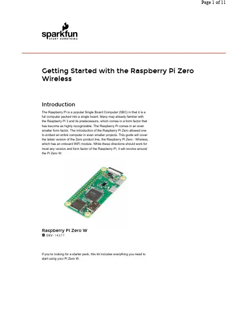
IntroductionThe Raspberry Pi is a popular Single Board Computer (SBC) in that it is a full computer packed into a single board. Many may already familiar with the Raspberry Pi 3and its predecessors, which comes in a form factor that has become as highly recognizable. The Raspberry Pi comes in an even smaller form factor. The introduction of the Raspberry Pi Zero allowed one to embed an entire computer in even smaller projects. This guide will cover the latest version of the Zero product line, the Raspberry Pi Zero -Wireless, which has an onboard WiFi module. While these directions should work for most any version and form factor of the Raspberry Pi, it will revolve around the Pi Zero W.
If you’re looking for a starter pack, this kit includes everything you need to start using your Pi Zero W.

树莓派基本使用方法树莓派呀,就像是一个超迷你的小电脑,可好玩啦。
拿到树莓派之后呢,你得先给它找个“家”,这个“家”就是电源啦。
得用合适的电源给它供电,不然它可没法工作哟。
一般来说,按照说明书上推荐的电源规格来就好啦。
然后就是存储设备啦。
树莓派可以用SD卡来存储数据和系统。
你得先把系统镜像烧录到SD卡里面。
这就像给它的小脑袋里装上思想一样。
网上有专门的烧录工具,操作起来也不是很难,按照提示一步步来就行。
再说说连接设备吧。
它有好多接口呢。
如果想让它显示画面,就可以用HDMI线把它和显示器连接起来,就像给它接上了一个大眼睛,可以看到它显示的东西啦。
要是想让它上网,还可以接上以太网线,这样它就能畅游网络世界啦。
还有啊,树莓派的操作系统也很有趣。
比较常用的是Raspbian系统。
这个系统很适合初学者,就像一个贴心的小管家,能帮你管理树莓派的各种功能。
在系统里,你可以像在普通电脑上一样,安装各种软件。
不过要注意软件的兼容性哦。
你要是想玩点有趣的项目,比如说做个小的智能家居控制器。
那你就可以把树莓派和一些传感器连接起来。
像温度传感器、光线传感器之类的。
然后通过编写简单的程序,就能让树莓派根据传感器传来的数据做出反应啦。
比如说温度高了就自动打开小风扇之类的,超酷的。
树莓派还可以用来搭建一个小的服务器呢。
可以共享文件或者搭建一个小型网站。
不过这可能就需要你多学一点网络知识啦。
但是别怕,网上有好多教程可以参考,就像有好多热心的小伙伴在旁边指导你一样。
总之呢,树莓派就像一个充满无限可能的小盒子。
只要你有想法,就可以慢慢探索它的各种玩法。
刚开始可能会遇到一些小问题,但是别灰心,这都是探索过程中的小插曲,慢慢你就会发现它的乐趣啦。

Colophon© 2020 Raspberry Pi (Trading) Ltd.This documentation is licensed under a Creative Commons Attribution-NoDerivatives 4.0 International (CC BY-ND).build-date: 2021-10-19build-version: githash: 91fd59e-cleanLegal Disclaimer NoticeTECHNICAL AND RELIABILITY DATA FOR RASPBERRY PI PRODUCTS (INCLUDING DATASHEETS) AS MODIFIED FROM TIME TO TIME (“RESOURCES”) ARE PROVIDED BY RASPBERRY PI (TRADING) LTD (“RPTL) "AS IS" AND ANY EXPRESS OR IMPL IED WARRANTIES, INCL UDING, BUT NOT L IMITED TO, THE IMPL IED WARRANTIES OF MERCHANTABIL ITY AND FITNESS FOR A PARTICUL AR PURPOSE ARE DISCL AIMED. TO THE MAXIMUM EXTENT PERMITTED BY APPL ICABL E L AW IN NO EVENT SHAL L RPTL BE L IABL E FOR ANY DIRECT, INDIRECT, INCIDENTAL, SPECIAL, EXEMPL ARY, OR CONSEQUENTIAL DAMAGES (INCL UDING, BUT NOT L IMITED TO, PROCUREMENT OF SUBSTITUTE GOODS OR SERVICES; LOSS OF USE, DATA, OR PROFITS; OR BUSINESS INTERRUPTION) HOWEVER CAUSED AND ON ANY THEORY OF L IABIL ITY, WHETHER IN CONTRACT, STRICT L IABIL ITY, OR TORT (INCL UDING NEGL IGENCE OR OTHERWISE) ARISING IN ANY WAY OUT OF THE USE OF THE RESOURCES, EVEN IF ADVISED OF THE POSSIBIL ITY OF SUCH DAMAGE.RPTL reserves the right to make any enhancements, improvements, corrections or any other modifications to the RESOURCES or any products described in them at any time and without further notice.The RESOURCES are intended for skilled users with suitable levels of design knowledge. Users are solely responsible for their selection and use of the RESOURCES and any application of the products described in them. User agrees to indemnify and hold RPTL harmless against all liabilities, costs, damages or other losses arising out of their use of the RESOURCES.RPTL grants users permission to use the RESOURCES solely in conjunction with the Raspberry Pi products. All other use of the RESOURCES is prohibited. No licence is granted to any other RPTL or other third party intellectual property right.HIGH RISK ACTIVITIES. Raspberry Pi products are not designed, manufactured or intended for use in hazardous environments requiring fail safe performance, such as in the operation of nuclear facilities, aircraft navigation or communication systems, air traffic control, weapons systems or safety-critical applications (including life support systems and other medical devices), in which the failure of the products could lead directly to death, personal injury or severe physical or environmental damage (“High Risk Activities”). RPTL specifically disclaims any express or implied warranty of fitness for High Risk Activities and accepts no liability for use or inclusions of Raspberry Pi products in High Risk Activities.Raspberry Pi products are provided subject to RPTL’s Standard Terms. RPTL’s provision of the RESOURCES does not expand or otherwise modify RPTL’s Standard Terms including but not limited to the disclaimers and warranties expressed in them.IntroductionThe Raspberry Pi Build HAT is an add-on board that connects to the 40-pin GPIO header of your Raspberry Pi, which was designed in collaboration with LEGO® Education to make it easy to control LEGO® Technic™ motors and sensors with Raspberry Pi computers.It provides four connectors for LEGO® Technic™ motors and sensors from the SPIKE™ Portfolio. The available sensors include a distance sensor, a colour sensor, and a versatile force sensor. The angular motors come in a range of sizes and include integrated encoders that can be queried to find their position.The Build HAT fits all Raspberry Pi computers with a 40-pin GPIO header, including — with the addition of a ribbon cable or other extension device — Raspberry Pi 400. Connected L EGO® Technic™ devices can easily be controlled in Python, alongside standard Raspberry Pi accessories such as a camera module.The Raspberry Pi Build HAT power supply, available separately, is designed to power both the Build HAT and Raspberry Pi computer along with all connected LEGO® Technic™ devices.The L EGO® Education SPIKE™ Prime Set 45678 and SPIKE™ Prime Expansion Set 45681, available separately from LEGO® Education resellers, include a collection of useful elements supported by the Build HAT.NOTEThe HAT works with all 40-pin GPIO Raspberry Pi boards, including Raspberry Pi 4 and Raspberry Pi Zero. With the addition of a ribbon cable or other extension device, it can also be used with Raspberry Pi 400.•Controls up to 4 LEGO® Technic™ motors and sensors included in the SPIKE™ Portfolio•Easy-to-use Python library to control your LEGO® Technic™ devices•Fits onto any Raspberry Pi computer with a 40-pin GPIO header•Onboard RP2040 microcontroller manages low-level control of LEGO® Technic™ devices•External 8V PSU available separately to power both Build HAT and Raspberry PiPreparing your Raspberry PiRaspberry Pi recommend the use of Raspberry Pi Imager to install an operating system on your SD card. You will need another computer with an SD card reader to install the image.Using Raspberry Pi ImagerRaspberry Pi have developed a graphical SD card writing tool that works on Mac OS, Ubuntu 18.04, and Windows called Raspberry Pi Imager; this is the easiest option for most users since it will download the image automatically and install it to the SD card.Download the latest version of Raspberry Pi Imager and install it. If you want to use Raspberry Pi Imager from a second Raspberry Pi, you can install it from a terminal using sudo apt install rpi-imager. Then:•Connect an SD card reader with the SD card inside.•Open Raspberry Pi Imager and choose the required OS from the list presented.•Choose the SD card you wish to write your image to.•Review your selections and click on the Write button to begin writing data to the SD Card.NOTEIf using Raspberry Pi Imager on Windows 10 with controlled folder access enabled, you will need to explicitly allow Raspberry Pi Imager permission to write the SD card. If this is not done, the imaging process will fail with a "failed to write" error.You can now insert the SD card into the Raspberry Pi and power it up. For Raspberry Pi OS, if you need to manually log in, the default user name is pi, with password raspberry, and the default keyboard layout is set to United Kingdom (UK).You should change the default password straight away to ensure your Raspberry Pi is secure.Configuring the Serial PortOnce the Raspberry Pi has booted, open the Raspberry Pi Configuration tool by clicking on the Raspberry Menu button and then selecting “Preferences” and then “Raspberry Pi Configuration”.Click on the “interfaces” tab and adjust the Serial settings as shown below:to the Raspberry PiBuild HAT.Using a Headless Raspberry PiIf you are running your Raspberry Pi headless and using raspi-config, select “interface options from the first menu”.the serial connectionto the Raspberry PiBuild HAT usingraspi-config.Then “P6 Serial Port”.the serial connectionto the Raspberry PiBuild HAT usingraspi-config.Disable the serial console:Figure 4. Configuringthe serial connectionto the Raspberry PiBuild HAT usingraspi-config.And enable the serial port hardware.Figure 5. Configuringthe serial connectionto the Raspberry PiBuild HAT usingraspi-config.The final settings should look like this.to the Raspberry PiBuild HAT usingraspi-config.You will need to reboot at this point if you have made any changes.Preparing the Build HATAttach 9mm spacers to the bottom of the board. Seat the Raspberry Pi Build HAT onto your Raspberry Pi. Make sure youput it on the right way up. Unlike other HATs, all the components are on the bottom, leaving room for a breadboard orLEGO elements on top.Figure 7. Fitting theBuild HAT to yourRaspberry PiAccess the GPIO PinsIf you want to access the GPIO pins of the Raspberry Pi, you can add an optional tall header and use 15 mm spacers, seeFigure 8.Figure 8. TheRaspberry Pi BuildHAT connected usingthe optional tallheader and 15mmspacers.The following pins are used by the Build HAT itself and you should not connect anything to them.Powering the Build HATConnect an external power supply — the official Raspberry Pi Build HAT power supply is recommended — however anyreliable +8V±10% power supply capable of supplying 48W via a 5.5mm × 2.1mm × 11mm centre positive barrel connectorwill power the Build HAT. You don’t need to connect an additional USB power supply to the Raspberry Pi as well, unlessyou are using a Raspberry Pi 400.NOTEThe Build HAT can not power the Raspberry Pi 400 as it does not support being powered via the GPIO headers.Figure 9. Powering theBuild HAT using theRaspberry Pi BuildHAT power supply.NOTEThe LEGO® Technic™ motors are very powerful; so to drive them you’ll need an external 8V power supply. If you wantto read from motor encoders and the SPIKE™ force sensor, you can power your Raspberry Pi and Build HAT the usualway, via your Raspberry Pi’s USB power socket. The SPIKE™ colour and distance sensors, like the motors, require anexternal power supply.Connecting a MotorConnect a motor to port A on the Build HAT. The LPF2 connectors need to be inserted the correct way up. If the connectordoesn’t slide in easily, rotate by 180 degrees and try again.the Build HATInstalling the SoftwareInstall the Build HAT Python library. Open a Terminal window and type,$ pip3 install buildhatFor more information about the Build HAT Python Library see https://buildhat.readthedocs.io/.Start the Thonny IDE. Add the program code below:1 from buildhat import Motor23 motor_a = Motor('A')45 motor_a.run_for_seconds(5)Run the program by clicking the play/run button. If this is the first time you’re running a Build HAT program since the Raspberry Pi has booted, there will be a few seconds pause while the firmware is copied across to the board. You should see the red LED extinguish and the green LED illuminate. Subsequent executions of a Python program will not require this pause.Your motor should turn clockwise for 5 seconds.Change the final line of your program and re-run.5 motor_a.run_for_seconds(5, speed=50)The motor should now turn faster. Make another change:5 motor_a.run_for_seconds(5, speed=-50)The motor should turn in the opposite (anti-clockwise) directionCreate a new program by clicking on the plus button in Thonny. Add the code below:from buildhat import Motormotor_a = Motor('A')While True:print("Position: ", motor_a.get_aposition())Run the program. Grab the motor and turn the shaft. You should see the numbers printed in the Thonny REPL changing.Connect a Colour sensor sensor to port B on the Build HAT, and a Force sensor to port C.If you’re not intending to drive a motor, then you don’t need an external power supply and you can use a standard USB power supply for your Raspberry Pi.Create another new program:1 from signal import pause2 from buildhat import ForceSensor, ColorSensor34 button = ForceSensor('C')5 cs = ColorSensor('B')67 def handle_pressed():8 cs.on()9 print(c.get_color())1011 def handle_released():12 cs.off()Run it and hold a coloured object (L EGO elements are ideal) in front of the colour sensor and press the Force sensor plunger. The sensor’s LED should switch on and the name of the closest colour should be displayed in the thonny REPL.。

树莓派入门册程亚红2017年9月目录第一章准备工作第二章烧录镜像第三章接线、点亮第四章散热片的安装第五章外壳及小风扇的安装一、准备工作必备物品:树莓派主板、电源、电源线、TF卡、TF卡读卡器、HDMI高清数据线、网线、散热片(3个)、小风扇、外壳。
温馨提示:①亲们直接拍下本店树莓派套餐即可,套餐里面的东西都是运行树莓派所必须的,缺一不可。
②大家可以根据自己的喜好选择3.5寸、7寸或者10寸三种尺寸的显示屏。
③如果您的家里有显示屏,但是接口是如图1所示的样子,那么您还需要额外购买一根HDMI转VGA转接线(本店有售),来连接显示屏和树莓派。
图1准备好这些东西,那么我们就可以开始行动啦!二、烧录镜像操作系统,镜像是资料里面带的标准镜像。
1.把镜像烧录到TF卡中(注意:第一次烧录的时候TF卡是空的,所以直接烧录进去即可,如果是第二次操作,需要先使用SD卡格式化软件,把SD卡格式化以后,再重新烧录新的固件。
)把需要解压的文件,先解压出来。
取出套件中的TF卡和读卡器,把TF插在读卡器上,然后把读卡器插在电脑上,留意一下读卡器在电脑中的盘符。
将读卡器接到电脑以后,打开刚解压出来的Win32DiskImager 程序:如果有报错的话,忽略掉,点OK继续。
点击右边的蓝色文件夹图标,然后选中刚才解压出来的Raspbian映像文件。
确保最右边Device中的盘符为你读卡器的盘符。
打开映像文件以后,点Write,然后点一下Yes确定操作。
整个写入过程需要一些时间来完成。
写入完毕以后,你会看到下面的信息,这时你就可以把你的Micro SD卡安全移除了。
三、接线、点亮注:本章使用的是7寸屏,其他类型的显示屏使用方法类似。
1.从电脑拔下读卡器,取出TF卡,插到树莓派背面的TF卡槽里,如下图所示。
2.接线:分别插上树莓派主板电源线,7寸屏电源线,用HDMI高清数据线连接7寸屏和树莓派主板。
3.确认接线无误后,把上图中的白色树莓派电源开关线拨到ON一边。

Stereo Camera Adapter BoardUser Guide: Set-Up InstructionsSKU: B0166INTRODUCTIONThis multi-camera adapter board is designed for Raspberry pi ZERO and let you connect two 5MP cameras to Pi Zero.Only one of the two cameras can be activated at a time, and they are working in alternate ways.It cannot run two cameras at the same time, but we build a simple software which can run two cameras and make it looks like working at the same time.But the drawback is the frame rate, and resolution will be fairly low, may be useful for surveillance.Please note that Raspberry Pi multi-cameraadapter board is a nascent product that may have some stability issues and limitations because of the cable’s signal integrity and RPi's closed source video core libraries, so use it on your own risk. This version doesn't support 8MP Pi camera board. And it also can be used for other Raspberry Pi boards with minor software modifications.You can find more information here at our website:/docs/cameras-for-rasp berry-pi/multi-camera-adapter-board/Email: *******************PREREQUISITESBecause the camera switching is done through the camera led pin. You have to disable the automatic management of camera led in /boot/config.txt . The following command helps you disable the led control from the GPU firmware.$ sudo sh -c 'echo "disable_camera_led=1" >> /boot/config.txt'$ sudorebootHARDWARE CONNECTIONConnect the multi-camera adapter board to Pi ZERO through 15-22pin flex cable. And connect two 5MP pi cameras to the Camera A and Camera B ports as the following photo shows.QUICK STARTDownload the Raspberrypi librarygit clone https :// /ArduCAM /RaspberryPi.git pi@raspberrypi :~ $git clone https:///ArduCAM/RaspberryPi.gitShell versionThis shell script demonstrates how to take two still images from two cameras in turn.Each camera will preview for 5 seconds and then take a photo saved to the local file system. Users can directly see the tested pictures.Run the scriptcd RaspberryPi /Multi_Camera_Adapter /Multi_Adapter_Board_2Channel /shell sudo chmod +x pi_cam.sh sudo ./pi_cam.shRun the demopi@raspberrypi :~/RaspberryPi/Multi_Camera_Adapter/Multi_Adapter_Board_2Channel/shell $./pi_cam.sh The board is Pi 3B/B+.Set state of 134 to 1Choose camera A Set state of 134 to 0Choose Camera B Test OKC++ version codeThis example demonstrates to run two cameras and make them looks at the sameInstall the opencv library sudo apt-get install libopencv-devCompile and runcd RaspberryPi /Multi_Camera_Adapter /Multi_Adapter_Board_2Channel /c++/sudo make sudo ./pi_camRun the demo。
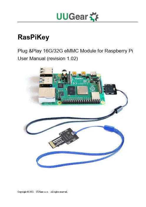
RasPiKeyPlug &Play 16G/32G eMMC Module for Raspberry Pi User Manual (revision 1.02)Table of ContentWhat is RasPiKey? (1)What is in the Package? (2)RasPiKeySpecifications (3)Before Booting with RasPiKey (4)Update Bootloader (Optionalfor Raspberry Pi 4B only) (4)Enable SSH Login and Configure Wi-Fi Connection (4)Using RasPiKey (7)DDR52 Timing Mode (8)Benchmarks (10)Acknowledgement (12)Revision History (13)What is RasPiKey?RasPiKey is a 16GB/32GB eMMC module that can be inserted into Raspberry Pi’s micro SD card slot. It works like a micro SD card with better read/write performance (especially for 4k read/write) and have longer lifetime.RasPiKey has Raspbian (Raspberry Pi OS) preinstalled and allows you configure SSH login and Wi-Fi connection before booting your Raspberry Pi. As a result, you can use your Raspberry Pi without display, keyboard and mouse, and access your Raspberry Pi via SSH session on your PC.RasPiKey is a “plug and play” accessory to most Raspberry Pi models. If you have Raspberry Pi 4B from rather old batch, which has rather old firmware that could not recognize RasPiKey, you may need to update the bootloader of your Raspberry Pi 4B beforehand.There are two varieties of RasPiKey: the 16GB RasPiKey comes with a black lanyard, while the 32GB RasPiKey comes with a blue one.What is in the Package?Each RasPiKey package contains:●RasPiKeyboard x 1●lanyardx 1* 32GB version has lanyard in blue color instead.RasPiKeySpecificationsBefore Booting with RasPiKeyIf you are not using Raspberry Pi 4B, and you have display, keyboard and monitor connected to your Raspberry Pi, you can just insert RasPiKey into the micro SD card slot and directly use it like a normal SD card. RasPiKey already have OS pre-installed, so it can directly boot your Pi.Update Bootloader (Optionalfor Raspberry Pi 4B only)If you are using Raspberry Pi 4B, you may (or may not) need to update the bootloader to have RasPiKey supported.It depends on the Raspberry Pi 4 you have: earlier batch of Raspberry Pi 4 may have rather old bootloader, which could not recognize RasPiKey. If your Raspberry Pi 4 is recently purchased, then most probably you don't need to update its bootloader, and it can be directly boot with RasPiKey.You can run this command to verify the bootloader on your Pi 4:If the printed release date of bootloader is later than September 3rd2020, then you don’t need to update bootloader for your Pi 4.In case you need to update bootloader. You can find the official released bootloader here.Here we offer a much simpler way to update the bootloader:1.Download this update_bootloader.zip file, or you can find it in RasPiKey’s boot partition.2.Extract its content to a micro SD card3.Insert the micro SD card into Raspberry Pi and power on4.Wait for one minute.5.Power off and remove the micro SD card.After going through these steps, you have updated the bootloader on your Raspberry Pi 4B, and now it can work with RasPiKey.Enable SSH Login and Configure Wi-Fi ConnectionIf you want to use your Raspberry Pi without connecting any monitor, keyboard or mouse, you can enable SSH login and configure Wi-Fi connection before you boot your Raspberry Pi with RasPiKey. You will need a computer with micro SD card reader. If your computer doesn’t come with micro SD card reader, you can use a USB SD card reader.After inserting RasPiKey into micro SD card reader, its “boot” partition will be recognized as a USB disk on your computer (usually named “boot”). There you can find these files:∙RasPiKey.exe∙RasPiKey_MAC∙RasPiKey_ARM∙RasPiKey_X86∙RasPiKey.zipDepending on the computer and operating system you are using, you will use one of them to finish the configuration:When you run an executable file, it will request you to input some parameters to configure Wi-Fi connection:If you d on’t have Wi-Fi, or you prefer to use cable to connect Raspberry Pi to the network, you can input some dummy data here. The programme will generate the“wpa_supplicant.conf” file and the empty“ssh” file in the same directory. The “wpa_supplicant.conf” fil e contains the parameters to configure Wi-Fi connection, while the empty “ssh” file will enable the SSH login for you.If for any reason you cannot run the suitable executable file, you can extract the RasPiKey.zip file and edit the “wpa_supplicant.conf” file. The “ssh” file doesn’t need to be edited because it is empty. Remarks: the “wpa_supplicant.conf” and “ssh” files will be automatically removed after booting your Raspberry Pi with RasPiKey, however the configuration has been made and you don’t have to do it again (unless your Wi-Fi parameters get changed).Using RasPiKeyYou can use RasPiKey like a normal micro SD card with OS installed. You insert it into the micro SD card slot on Raspberry Pi, and then power it on.If your Raspberry Pi has display, keyboard and mouse connected, you have nothing to worry about and immediately enjoy using your Pi with RasPiKey.If your Pi doesn’t have display, keyboard or mouse, you may want to use it via SSH session, which needs your Pi to be connected to your network. If you have configured the Wi-Fi connection beforehand, you just need to wait until your Raspberry Pi finishes the boot and connect to your Wi-Fi. Or you use a network cable to connect Raspberry Pi to your local network.Given the empty “ssh” file is in RasPiKey’s boot partition, you can ensure SSH login will be enabled on your Raspberry Pi.During the first boot with RasPiKey, your Raspberry Pi will adjust the pattern size and reboot, this will make it a little longer until you can SSH it.You can use this command to login via SSH session:Sometimes it may complain about not knowing the “raspberrypi” host. In the majority of cases this problem will disappear after waiting for a while. If the problem persists, you can use this command to list all machines in your network:This command exists in Windows, Mac OS X and Linux, what a handy tool!If you run this command before and after booting your Raspberry Pi, you can figure out which IP address is for your Pi, by comparing the outputs of this command. Then you can login with:DDR52 Timing ModeDDR mode for eMMC was introduced in MMC 4.4 standard. The DDR52 timing mode can support frequency up to 52MHz and can almost double the performance of eMMC module (such as RasPiKey) on Raspberry Pi.In order to support DDR52 mode, your Raspberry Pi may need to have the firmware upgraded. Although the patch for supporting DDR52 timing mode has been committed, at the time of writing this chapter, the patch has not been replicated to the official repository yet, once it does, you can upgrade the firmware with these commands:After the upgrade and reboot your Raspberry Pi, you can run this command to confirm if the DDR52 mode has been supported:It should print out something like this:clock: 52000000 Hzactual clock: 50000000 Hzvdd: 21 (3.3 ~ 3.4 V)bus mode: 2 (push-pull)chip select: 0 (don't care)power mode: 2 (on)bus width: 2 (4 bits)timing spec: 8 (mmc DDR52)signal voltage: 0 (3.30 V)driver type: 0 (driver type B)The result above means the DDR52 timing mode has been supported, and your RasPiKey has much better performance on Raspberry Pi 4.However, if you see something different, like this:clock: 52000000 Hzactual clock: 50000000 Hzvdd: 21 (3.3 ~ 3.4 V)bus mode:2 (push-pull)chip select: 0 (don't care)power mode: 2 (on)bus width: 2 (4 bits)timing spec: 1 (mmc high-speed)signal voltage: 0 (3.30 V)driver type: 0 (driver type B)It means you need to upgrade the firmware to support the DDR52 timing mode.You can run this command to make the upgrade:BenchmarksWe follow Jeff Geerling’s blog posts (thank you Jeff) to do the benchmarks for RasPiKey. Jeff wrote this blog post about the benchmarks on Raspberry Pi 3B+. We do exactly the same benchmarks with RasPiKey and append the result to the diagram from Jeff’s blog post:Benchmarks on Raspberry Pi 3B+Jeff also wrote another blog post about the benchmarks on Raspberry Pi 4B.Again we do exactly the same benchmarks with RasPiKey and append the result to the diagram from Jeff’s blog post:Benchmarks on Raspberry Pi 4B (with DDR52 timing mode supported by firmware) Please notice the benchmarks above are obtained on Raspberry Pi 4B with firmware updated to support DDR52 timing mode. Please read the DDR52 Timing Mode chapter for more details.AcknowledgementWe would like to thank Tim Gover (Raspberry Pi Trading Ltd) and his teamon supporting RasPiKey (and other eMMC modules) on Raspberry Pi 4B, and their works on supporting the new DDR52 timing mode.We would also like to thank Dr. Tomas Lindén, who promoted the supporting of DDR52 timing mode on Raspberry Pi, reminded us about the firmware upgrade, and also provided us important information to perform further tests.Revision History。
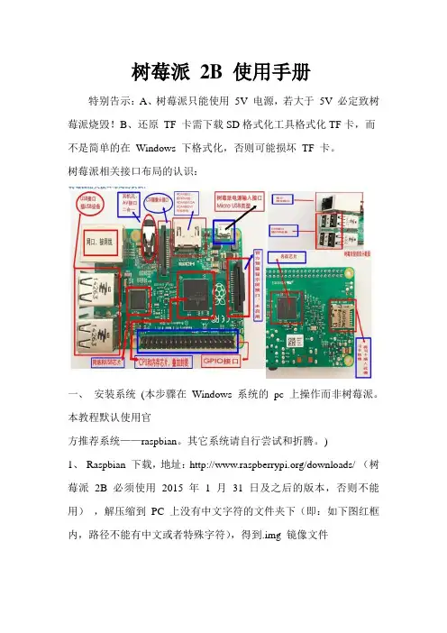
树莓派2B 使用手册特别告示:A、树莓派只能使用5V 电源,若大于5V 必定致树莓派烧毁!B、还原TF 卡需下载SD格式化工具格式化TF卡,而不是简单的在Windows 下格式化,否则可能损坏TF 卡。
树莓派相关接口布局的认识:一、安装系统(本步骤在Windows 系统的pc 上操作而非树莓派。
本教程默认使用官方推荐系统——raspbian。
其它系统请自行尝试和折腾。
)1、Raspbian 下载,地址:/downloads/ (树莓派2B 必须使用2015 年 1 月31 日及之后的版本,否则不能用),解压缩到PC 上没有中文字符的文件夹下(即:如下图红框内,路径不能有中文或者特殊字符),得到.img 镜像文件2、下载镜像安装工具win32 disk imager: /aKtGY ,解压缩到PC上:3、将TF 卡(最少8G 容量)插入读卡器(别用笔记本自带卡槽,否则刷的系统极可能不完整,存在问题),在PC 上打开win32diskimager.exe,如上图;点击按钮1,选择第1 步得到的img 镜像文件;点击按钮2 选择TF 卡的盘符;点击按钮3(write)开始给TF 卡写入系统,其中会提示对话框,点YES 即可;点击按钮4(read)是备份(导出)TF 卡已装系统。
装系统由TF 卡写入速度决定,8 分钟左右。
系统安装成功后会提示“Write Successful”(装系统时勿做其他操作,存在系统写入失败损坏TF 卡的可能)。
此时关闭imager 工具,但别拔出TF 卡。
这时TF 卡只显示剩下几十M,正常的!这是由于TF 卡在装了Linux 系统后,分为三种格式,其中只有一种格式能被Windows 系统识别,也就是剩下那几十M。
二、系统配置1)、注意:若使用A V(RCA)接口电视,本步骤可忽略,但2B 须使用“3.5mm 转接头转换后”才可正常使用。
2)、HDMI、DVI 或VGA 接口显示器用户需要修改配置文件:在PC 上进入TF 卡,并找到文件config.txt,使用3、Notepad++(下载:/pVN9A )工具打开,依次将下面项目的“值”修改为等号后的数值,并去掉前面的“#”:hdmi_force_hotplug=1hdmi_gryuoup=2hdmi_mode=16hdmi_drive=2config_hdmi_boost=4sdtv_mode=2arm_freq=800项目释义:hdmi_mode=16 是分辨率修改项,通常为4、9、16;hdmi_drive=2,表示音频从HDMI 接口输出;arm_freq=800 为调频项,可为900、1000,修改前请务必做好散热准备,谨慎尝试,后果自负。

树莓派开发手册(实用版)目录1.树莓派简介2.树莓派硬件配置3.树莓派软件安装与设置4.树莓派编程与开发5.树莓派应用案例6.树莓派社区与资源正文【树莓派简介】树莓派是一款基于 Linux 系统的微型计算机,由英国 Raspberry Pi 基金会推出。
它具有小巧的尺寸、低廉的价格以及强大的功能,因此受到了全球开发者、教育者和爱好者的欢迎。
【树莓派硬件配置】树莓派有多个型号,如 Raspberry Pi 4、Raspberry Pi 3 等。
它们的主要硬件配置包括:处理器、内存、存储空间、网络接口、USB 接口、HDMI 接口等。
其中,处理器和内存对计算机性能影响最大。
【树莓派软件安装与设置】树莓派需要安装操作系统,推荐使用 Raspbian,这是专门为树莓派定制的 Linux 发行版。
安装过程中需要对系统进行一些基本设置,例如设置主机名、修改密码、更新系统等。
【树莓派编程与开发】树莓派支持多种编程语言,如 Python、C++、Java 等。
开发者可以通过命令行或 GUI 界面进行编程。
此外,树莓派还支持各种开发工具和库,如 Python 库、OpenCV 等。
【树莓派应用案例】树莓派可以应用于多种场景,如智能家居、机器人、媒体中心、游戏机等。
此外,树莓派在教育领域也有广泛应用,如编程教育、物联网实验等。
【树莓派社区与资源】树莓派拥有庞大的社区和丰富的学习资源。
社区提供了丰富的技术支持和教程,帮助开发者解决各种问题。
同时,网上也有很多关于树莓派的教程、案例和项目,供开发者学习和借鉴。
总之,树莓派凭借其优越的性能和灵活的应用场景,已经成为了开发者和教育者的重要工具。

树莓派使用指南树莓派是一款单板计算机,它小巧便携,可以应用于各种场景。
本文将为大家介绍如何使用树莓派。
一、购买树莓派你需要购买一台树莓派。
树莓派有多个型号,每个型号的配置和价格不同。
一般来说,初学者可以选择树莓派3B+或4B,这两款型号都有良好的性能和广泛的应用场景。
二、安装系统购买树莓派后,你需要安装系统。
树莓派支持多种操作系统,例如Raspbian、Ubuntu、Debian等。
其中,Raspbian是官方推荐的系统,初学者可以选择安装它。
安装系统有两种方式,一种是使用官方提供的SD卡镜像文件,将其烧录到SD卡中,然后插入树莓派中启动即可;另一种是使用网络安装,即通过网络连接下载系统并安装。
初学者可以选择SD卡烧录方式安装系统。
三、连接硬件安装系统后,你需要连接树莓派的硬件,例如显示器、键盘、鼠标、网线等。
连接方式有多种,具体可以参考树莓派官方文档或相关论坛。
四、使用树莓派连接硬件后,你可以开始使用树莓派了。
树莓派可以用来做很多事情,例如搭建服务器、学习编程、控制硬件等。
如果你想搭建服务器,可以使用Apache或Nginx等Web服务器软件,搭建网站或Web应用程序。
如果你想学习编程,可以使用Python或C等语言,编写程序并在树莓派上运行。
如果你想控制硬件,可以使用GPIO接口,连接LED灯、温度传感器、红外线发射器等硬件。
五、注意事项在使用树莓派时,需要注意以下事项:1.不要随意拔插SD卡和硬件,这可能会导致文件系统损坏或硬件损坏。
2.使用树莓派时,保持良好的通风环境,避免过热。
3.使用树莓派时,需要注意电源适配器的功率和电压,不要使用不合适的电源适配器。
4.在使用树莓派时,遵循网络安全原则,保护好你的数据和隐私。
六、总结本文介绍了树莓派的购买、安装、连接硬件和使用等方面的内容,希望可以帮助初学者快速上手树莓派。
在使用树莓派时,需要注意安全和稳定性,避免不必要的损失。

树莓派开发手册树莓派是一款小巧而功能强大的微型计算机,广泛应用于各种领域的科研和教育项目中。
它可以运行各种操作系统,如Raspbian、Ubuntu等,支持多种编程语言,如Python、C++等,因此备受开发者们的喜爱。
首先,让我们来了解一下树莓派的硬件配置。
树莓派通常包括一个主板和一些必要的配件,如电源适配器、MicroSD卡、HDMI线等。
主板上有一颗处理器、内存、GPIO引脚等组件,可以连接各种传感器、摄像头、显示器等外设,实现更多功能。
其次,我们需要了解如何启动树莓派。
首先将操作系统烧录到MicroSD卡中,插入树莓派主板,连接电源、显示器、键盘鼠标等设备,然后开机即可。
在第一次启动时,系统会引导用户设置一些基本配置,如语言、时区、密码等。
接着,我们可以开始编写程序。
树莓派支持多种编程语言,但最常用的是Python。
通过Python编写的程序可以实现各种功能,如控制LED灯、读取温度传感器、拍摄照片等。
此外,树莓派还支持远程控制,用户可以通过SSH、VNC等方式连接到树莓派,进行远程操作。
在开发过程中,我们还需要了解一些常用的库和工具。
例如RPi.GPIO库用于控制GPIO引脚,Picamera库用于控制摄像头,OpenCV库用于图像处理等。
此外,树莓派还可以搭建Web服务器、数据库等,实现更多复杂的功能。
最后,我们需要注意一些开发技巧。
首先要保持代码的简洁和可读性,避免写出冗长和难以理解的代码。
其次要注重错误处理和异常处理,及时排除程序中的bug。
最后要不断学习和探索,了解更多关于树莓派开发的知识,不断提升自己的技术水平。
总的来说,树莓派是一款非常适合初学者的开发平台,它不仅功能强大,而且价格低廉,非常适合用来学习编程和电子技术。
希望通过本文的介绍,读者们对树莓派有了更深入的了解,能够更好地利用它来进行开发。
愿大家在树莓派的世界里不断探索,不断创新,实现更多有趣的项目和应用。
这篇教程将带您一起玩转树莓派3(Raspberry Pi3)。
和普通PC一样,拿到新设备第一件事就是要给它安装一个操作系统,并做一些初始化的操作。
比PC简单的是,树莓派是一个固定配置的硬件板子,并没有像PC那样有很多硬件组合的情况,因此可以很方便的给它打造一个专用的系统。
安装系统主要就是一个存储卡镜像写入的过程,装好后进行很少的配置就可以开始使用,而且这个镜像里已经预装了不少工具软件和游戏哦。
1准备工作树莓派支持非常多种操作系统。
这里简单列举如下:图片来自树莓派官方网站()下面链接给出了更详细的列表,供有兴趣的朋友参考:https:///wiki/Raspberry_Pi#Software看完列表是不是各位的选择困难症都要犯了,其实有官方支持同时也是使用比较广泛的就是Raspbian,这是一个基于Debian的为树莓派量身定做的系统。
接下来详细说明如何安装这个系统,并初始化开始使用它。
1.1需要准备的硬件树莓派需要的配件在设计时就考虑了广泛的兼容性,要找齐它们肯定难不倒各位爱折腾的小伙伴,但是,并不是能插上就一定合适,下面提醒一些需要注意的地方。
PC1台台式机笔记本都可以,需要联网用于下载软件,需要有一个TF卡读卡器,用于读写TF卡。
如果没有,可以外接1个USB读卡器。
PC操作系统也是随意的,当然我这里以使用最广泛的Windows为例(XP、7、8、10应该都可以,我使用的是Windows7)。
树莓派1个各版本的树莓派安装系统过程和基本操作都差不多,这里当然以Raspberry Pi3Model B为例。
TF卡1张TF卡就是Micro SD卡,就是能插卡扩展容量的手机上用的那种。
容量上8GB就够,当然大一点好,另外速度也要考虑,建议买速度快一点,质量好一点的卡,毕竟这相当于Raspberry Pi的系统盘。
电源1个电源接口是Micro USB,但并不是所有的手机充电器都能用。
官方要求是5V2.5A。
RS485 CAN HATUser Manual OVERVIEWThe RS485 CAN HAT will enables your Pi to communicate with other devices stably in long-distance via RS485/CAN functions.FEATURES⚫Raspberry Pi connectivity, compatible with Raspberry Pi Zero/Zero W/Zero WH/2B/3B/3B+⚫CAN function, onboard CAN controller MCP2515 via SPI interface, with transceiver SN65HVD230⚫RS485 function, controlled via UART, half-duplex communication, with transceiver SP3485⚫Reserved control pins, allows to work with other control boards⚫Comes with development resources and manual (examples in wiringPi/python) SPECIFICATIONSOperating voltage : 3.3VCAN controller : MCP2515CAN transceiver : SN65HVD230 485 transceiver : SP3485 Dimension : 65mm x 30mm Mounting hole size : 3.0mm INTERFACESCAN:RS485:Overview (1)Features (1)Specifications (1)Interfaces (2)Hardware Description (5)CAN BUS (5)RS485 BUS (6)How to use (8)Libraries installtion (8)CAN test (9)Hardware (9)Preparation (9)C code example (10)Python example (11)RS485 Test (12)Hardware (12)Preparation (12)Python code (14)Code Analysis (15)CAN (15)C code (15)Python (18)RS485 (20)wiringPi code (20)Python code (22)HARDWARE DESCRIPTIONCAN BUSCAN module could process packets transmit/receive on CAN bus. Packets transmit: first store packet to related buffer and control register. Use SPI interface to set the bits on control register or enable transmit pin for transmitting. Registers could be read for detecting communication states and errors. It will first check if there are any errors of packets detected on CAN bus, then verify it with filter which is defined by user. And store packet to one of buffers if it has no errors.Raspberry Pi cannot support SPI bus, so this module use SPI interface and on board an receiver/transmitter for CAN communication.Mi crochip Technology’sMCP2515 is a stand-alone ControllerArea Network (CAN) controller thatimplements the CAN specification,version 2.0B. It is capable of transmittingand receiving both standard andextended data and remote frames. The MCP2515 has two acceptance masks and six acceptance filters that are used to filter out unwanted messages, thereby reducing the host MCUs overhead. The MCP2515 interfaces with microcontrollers (MCUs) via an industry standard Serial Peripheral Interface (SPI), that is Raspberry Pi cancommunicate with MCP2515 via SPI interface without external driver. What we need to do is to enable the kernel driver on devices tree.For more details, please refer to datasheet.SN65HVD230 from TEXAS INSTRUMENTS is a CAN transceiver, which is designed for high communication frequency, anti-jamming and high reliability CAN bus communication. SN65HVD230 provide three different modes of operation: high-speed, slope control and low-power modes. The operation mode can be controlled by Rs pin. Connect the Tx of CAN controller to SN65HVD230’s data input pin D, can transmit the data of CAN node to CAN network; And connect the RX of CAN controller to SN65HVD230’s data input pin R to receive data.RS485 BUSThe SP3485 is a low power half-duplex transceiver that meet the specifications of RS485 serial protocols. RO is Receiver output pin and DI is Driver input pin. RE̅̅̅̅is Receiver Output Enable pin which is Active LOW and DE is Driver output Enable pin Active HIGH. A is Driver Output/Receiver input non-inverting port and B is DriverOutput/Receiver input, Inverting port. When A-B >+0.2V, RO pin will output logic 1; and when A-B<-0.2V, RO pin will output logic 0. 100Ωresistor is recommended to add between A and B ports.HOW TO USELIBRARIES INSTALLTIONTo use the demo codes, you should install libraries (wiringPi, bcm2835, python) first, otherwise the codes cannot work properly. About how to install libraries, you can refer to Wiki page:https:///wiki/Libraries_Installation_for_RPiFor python, you should install two more libraries as below:sudo apt-get install python-pipsudo pip install python-canVisit Waveshare Wiki: https:///wiki and search with “RS485 CAN CAPE”, download the demo code.Decompression and copy to Raspberry Pi.CAN TESTHARDWARERaspberry Pi 3B x2Waveshare RS485 CAN HAT x2PREPARATION1.Insert RS485 CAN HAT to Raspberry Pi, and then modify config.txt file:2.Append these statements to the file:3.Save and exit, then restart your Pi.4.After restart, check if initialize successfully:It will print information as below:The information will be different if RAS485 CAN HAT doesn’t be inse rted:In this case, you need to check if the module is connected? If SPI interface and CP2515 kernel driver is enable and restart Raspberry Pi.5.Connect the H and L port of RS485 CAN HAT to another’s.C CODE EXAMPLE1.List the folder of demo code you can get as below:2.Set one HAT as receiver: Enter the directory of receiver and run the code3.Set another as Sender: Enter the directory of send and run the codeAt the same time you can find the receiver receive the packet from sender:PYTHON EXAMPLE1.List the folder:2.Set the receiver first:3.Then the sender:RS485 TESTHARDWARERaspberry Pi 3B x2RS485 CAN HAT x2PREPARATIONThe serial of Raspberry Pi is used for Linux console output by default, so we need to disable it first:1.Run command to open raspi-config:2.Choose Interfaces Options ->Serial->no3.Open file /boot/config.txt, add the statement to the end:4.For Raspberry Pi, the serial port is used for Bluetooth, which should be commend:5.reboot Raspberry Pi6.C onnect A and B port of HAT to another’sWIRINGPI CODE1.List folders:2.Set receiver:3.Set sender:The packet received at receiver is as below:PYTHON CODE 1.List folders:2.First set receiver:3.Set sender:CANWe provide two codes for CAN communication, one is C code and another is python.C code use socket-can and python use similar libraries as well.C CODEThis example uses socket skill similar to network coding skill of Linux. If you have studied Linux network coding, you will familiar to it: Socketcan is method for CAN protocol in Linux.Step 1: Open socketif it failed it will return -1Step 2: Target device can0Step 3: Bind socket to CAN interface.Step 4: Set rule that only sendStep 5: Set the dataStep 6: Transmit dataCalling write() function to write the data to socket, it will return-1 if failed and return the number of byte if success. We could use the return value to check if it is successfully sending.Step 7: Close socket and CAN deviceNote: if you don’t close CAN device,system will prompt CAN bus is busy at next sending.For Receiving:1.It is different for binding socket2.The receive could be defined to only receive socket which ID is 0x1233.Read data read()Return number of bytes it read.For more information about socket-can coding please refer:https:///doc/Documentation/networking/can.txt PYTHONBefore use python sample, check if python-can library has been installed Build up CAN device first:Step 1: Connect to CAN busStep2: Create messageStep 3: Send messageStep 4: Finial close device as wellReceive Data:recv() define the timeout of receiving.For more information please refer to:https://python-can.readthedocs.io/en/stable/interfaces/socketcan.htmlRS485For RS485 communication, we provide two sample code, one is based on wiringPi library and another is Python.WIRINGPI CODESteps 1: Set Receiving and sendingThe RE and DE pin of SP3485 are used for enable input and output (Chapter Hardware description).The example code set module to sending states. the Pin18 is the ID based on bcm2835 libraries. For wiringPi, the pin id of bcm2835 is workable as well beside wiringpi pin id. wiringPiSetupGpio() is called for using bcm2835 pin id and wiringPiSetup() called for using wiringPi pin id.Step 2: Create file descriptor, open serial /dev/ttyS0 and set baudrateStep 3: Send dataThe serialGetchar(fd) function will return a character which is should used next of serial device, it will cause some wrong errors, so the sender should send a character “\r” to avoid this phenomenon. (If you have better way, kindly to contact us) For more information about functions, please refer to:/reference/serial-library/PYTHON CODEUsing Python to control RS485 will be much easy. Python could operate serial directly: Open serial file and set the baud rate as well.You can input the data you want to send and write it to serial file, after sending , it will return number of bytes:Reading:。