Dynamics of the Electro-Optic response of Blue Bronze
- 格式:pdf
- 大小:485.15 KB
- 文档页数:37
第18卷 第4期太赫兹科学与电子信息学报Vo1.18,No.4 2020年8月 Journal of Terahertz Science and Electronic Information Technology Aug.,2020 文章编号:2095-4980(2020)04-0570-05有机非线性光学晶体DAST的太赫兹发射性能李宝珠,武 聪,庞子博(中国电子科技集团公司第四十六研究所,天津 300220)摘 要:研究了DAST晶体的有效二阶非线性系数和太赫兹发射性能。
实验以DAST-甲醇溶液的亚稳区范围为依据,采用溶液降温法进行DAST的生长。
实验发现,降温速率越快,晶体的生长速度越快,但晶体易发生多晶转变;在晶体生长后期,采用较慢的降温速率,有利于晶体厚度的增加。
经磨抛后的晶体表面粗糙度能够达到光学测试等级(微米级)要求。
经测试,DAST晶片有效二阶非线性系数平均值为16.58pm/V,实现了频率范围0.84~10T H z的太赫兹波发射,并在2.72 THz处具有最大发射强度。
关键词:DAST晶体;太赫兹;有效二阶非线性系数;性能中图分类号:TN209文献标志码:A doi:10.11805/TKYDA2020097Terahertz emission properties of organic nonlinear optical crystal DASTLI Baozhu,WU Cong,PANG Zibo(No. 46 Research Institute of China Electronics Technology Group Corporation,Tianjin 300220,China)Abstract:The effective second-order nonlinearity and terahertz emission properties of DAST crystal are mainly studied. Based on the metastable region of DAST-methanol solution, the growth experiment ofDAST is carried out by solution cooling methods. It is found that the higher the cooling rate, the faster thecrystal growth rate, but the polycrystalline is easy to occur. In the later stage of crystal growth, the lowercooling rate is beneficial to the increase of crystal thickness. After grinding, the surface roughness of thepolished crystal could meet the optical test level(micron level) requirement. The average effective secondorder non-linear coefficient of DAST chip is 16.58 pm/V. Terahertz emission in the frequency range of0.84-10 THz is realized, and the maximum emission intensity is at 2.72 THz.Keywords:DAST;terahertz;effective second-order nonlinear coefficient;performance随着无线通信技术的发展,对无线通信速率和频率的要求逐年提高,现有无线通信频段已趋于饱和,而太赫兹频段是一个全新的空间[1]。

Home Search Collections Journals About Contact us My IOPsciencePreparation of MoO3 nanostructures and their optical propertiesThis content has been downloaded from IOPscience. Please scroll down to see the full text.2003 J. Phys.: Condens. Matter 15 L547(/0953-8984/15/35/101)View the table of contents for this issue, or go to the journal homepage for moreDownload details:IP Address: 61.158.219.226This content was downloaded on 17/10/2013 at 00:51Please note that terms and conditions apply.I NSTITUTE OF P HYSICS P UBLISHING J OURNAL OF P HYSICS:C ONDENSED M ATTER J.Phys.:Condens.Matter15(2003)L547–L552PII:S0953-8984(03)66383-6LETTER TO THE EDITORPreparation of MoO3nanostructures and their optical propertiesYe Zhao1,Jingguo Liu1,Ya Zhou1,Zhengjun Zhang1,4,Yonghua Xu2,H Naramoto2and S Yamamoto31Department of Materials Science and Engineering,Tsinghua University,Beijing100084,People’s Republic of China2Advanced Science Research Centre,JAERI,Takasaki,Gunma370-1292,Japan3Department of Material Development,JAERI,Takasaki,Gunma370-1292,JapanE-mail:zjzhang@Received22July2003Published22August2003Online at /JPhysCM/15/L547AbstractIn this letter we report the synthesis of nanostructures of molybdenum trioxidesby directly oxidizing a spiral coil of molybdenum,at ambient atmosphere,bypassing a current through the coil.The advantage of this approach is thatthe temperature of the substrate is low(normally below200◦C),and that thenanostructures to be formed could be chosen,via controlling the current or,equivalently,the temperature of the coil.We show that,by adjusting the currentthrough the coil,α-MoO3lamellas with a thickness of∼20–50nm,andβ-MoO3spheres of diameters down to nanometre scale can be synthesized at ambientatmosphere.These nanostructures exhibit a large optical band gap of∼3.05eV,and room-temperature photoluminescence at∼395nm.This study provides asimple,controllable way of fabricating metal oxide nanostructures of interest.Transition metal oxides comprise a large family of materials exhibiting a variety of interesting properties that are attractive for applications in lithium-ion batteries[1,2],catalysts[3], electrochromic materials[4,5],sensors[6,7],etc.Among the transition metal oxides,MoO3, due to its excellent optical and electronic properties,has become a promising material for applications in electrochromic systems ranging from microbatteries[8]and gas sensing[9]to devices for information displays[10,11].As many properties of nanosized transition metal oxides are distinct from their bulk forms,the synthesis,structure characterization and properties evaluation of these nanostructures have thus become the focus of research in recent years.Currently,there are several approaches available for preparing MoO3film with either an amorphous or a polycrystalline structure,e.g.,sputtering[4],chemical vapour deposition 4Author to whom any correspondence should be addressed.0953-8984/03/350547+06$30.00©2003IOP Publishing Ltd Printed in the UK L547(CVD)[12,13],electro-deposition[14]andflash evaporation[15,16].To fabricate nanoscopicMoO3,methods like template-directed reaction of molybdic acid and the subsequent leaching process[17],and templating against carbon nanotubes[18]have previously been attempted.These complicated approaches,however,are not able to bring growth of nanoscopic MoO3 structures on planar substrates,which is a necessity for applications in real devices.Therefore,new methodologies are demanded for the synthesis of nanostructured MoO3.Here,we report the synthesis of MoO3nanostructures by thermally oxidizing a molybdenum spiral coil at ambient atmosphere.Via adjusting the current passing throughthe coil or,equivalently,the temperature of the coil,nanostructures of MoO3,i.e.,α-MoO3lamellas,a mixture ofα-MoO3lamellas plusβ-MoO3nanospheres andβ-MoO3nanospheres can be synthesized in sequence as the temperature increases.Thus this study provides a simpleway for selecting the nanostructures of MoO3to be formed.A spiral coil(∼2cm in diameter and∼10cm long)made from a molybdenum wire with apurity of99.9%,was connected to two copper electrodes in a vacuum chamber.A voltage wasapplied to the two electrodes at ambient atmosphere to pass a current through the coil.The current was controlled via adjusting the voltage applied.A Si(001)substrate was supersonicallycleaned in acetone,alcohol and deionized water baths,and wasfixed on a substrate holder ∼5cm above the coil.Due to the oxidization of the molybdenum coil,nanostructures of molybdenum oxides were deposited on the substrate.The temperature of the coil wasmonitored using a WFH-655fibre-optic infrared thermometer.The temperature of the siliconsubstrate was measured by a thermal couple,and was found to be below200◦C within a typical deposition time of∼1min.The growth morphology,the structure and the optical properties of molybdenum oxide nanostructures deposited on the silicon substrates were examined and investigated using a scanning electron microscope(SEM),a transmission electron microscope (TEM),x-ray diffraction,micro-Raman spectroscopy and photoluminescence measurements, respectively.To investigate the effect of the temperature of the Mo spiral coil on the formation ofthe nanostructures,three currents,i.e.,∼25,∼50and∼75A were passed through the Mocoil,corresponding to temperatures of∼700,∼1000and∼1300◦C,respectively,monitored by thefibre-optic infrared thermometer.Figures1(a)–(f)show the SEM micrographs and corresponding Raman spectra of nanostructures deposited on the Si(001)substrate,at currents of∼25,50and75A,respectively.The SEM images were taken using a JSM-6301F SEM working at20kV.One sees that different nanostructures of molybdenum oxide were formed at three currents:at∼25A,lamellas were formed;at∼50A,a mixture of lamellas and spheres were formed;at∼75A,only spheres were formed.The lamellas are typically several micrometres long and sub-micrometre wide.Their thickness,as shown by the arrows in figure1(c),is∼several tens of nanometres.One may notice that the lamellas are so thin that they are transparent to the20keV electrons,i.e.,those spheres and lamellas beneath can be clearly seen from the image.The diameter of the spheres ranges from several tens to several hundreds of nanometres.The structure of these nanostructures was characterized with a micro-Raman spectrometerusing a514.5nm Ar+laser.The peaks infigures1(b)and(f)are readily indexed toα-MoO3of an orthorhombic structure andβ-MoO3of a monoclinic structure,respectively[19,20].Note that the peak at∼941cm−1infigure1(f)is from the silicon substrate.XRD analysis of two samples(not shown)also confirmed the results given by the Raman analysis.Figure1(d)shows, as one sees clearly,a spectrum of a mixture ofα-MoO3andβparingfigures1(a), (c)and(e),the lamellas infigure1(c)should beα-MoO3,and the spheres should beβ-MoO3. To confirm this,the deposits were mechanically removed from the substrate into alcohol by supersonic shaking,and dispersed onto another silicon substrate for micro-Raman analysis.Figure1.Morphologies and Raman spectra of molybdenum trioxides deposited on Si(001)substrates by passing different currents through a Mo spiral coil:(a)and(b)α-MoO3lamellasformed at∼25A;(c)and(d)a mixture ofα-MoO3lamellas andβ-MoO3nanospheres formed at∼50A;(e)and(f)β-MoO3nanospheres formed at∼75A,respectively.The numbers underlinedinfigure1(d)indicate peaks ofα-MoO3.In this way one can distinguish using a microscope the lamellas and nanospheres,and thus obtain Raman spectra from the lamellas or nanospheres only.The spectra obtained indicate clearly that the lamellas infigure1(c)areα-MoO3and the spheres areβ-MoO3.Therefore,by thermally oxidizing a molybdenum spiral coil,one could synthesize eitherα-MoO3lamellas orβ-MoO3nanospheres via controlling the current passing through the coil or,equivalently, the temperature of the coil.The structure of individual lamellas and nanospheres was also investigated by TEM andHRTEM analysis.Figures2(a)and(b)shows brightfield images,corresponding selected areaFigure 2.TEM and HRTEM characterization of(a)α-MoO3lamellas and(b)β-MoO3nanospheres.The insets of the two images are the corresponding SAD patterns.The arrow in(a)points to the lamella from which the SAD pattern was taken.diffraction(SAD)patterns and typical HRTEM images of theα-MoO3lamellas andβ-MoO3 nanospheres,respectively.The images and SAD patterns were taken with a JEM-2010F TEMworking at200kV.The lamellas,as can be seen from thefigure,are single crystalline,severalmicrometres long and sub-micrometre wide.From the indexing results of the SAD pattern (taken from the lamella indicated by the arrow infigure2(a))we note that the incident electronbeam is along the 010 and the growth direction of the lamellas is along the 100 ofα-MoO3.Theβ-MoO3spheres,as shown byfigure2(b),are of diameters varying from several tens to several hundreds of nanometres,and are also single crystalline.The optical properties ofα-MoO3lamellas andβ-MoO3nanospheres were evaluated by measuring their optical transmission in the range of ultraviolet to visible using aMPM-800microscopic photometer,and the photoluminescence spectra with a M-4500photoluminescence spectrometer.α-MoO3lamellas andβ-MoO3nanospheres show similar optical properties.Figure3is a typical optical transmission spectrum ofα-MoO3lamellas.The optical band gap of the lamellas can be obtained from the data at the absorption edgeusing the relationship of(αhν)1/2=A(hν−E g),where A is a constant,αis the absorption coefficient,hνis the photo energy and E g is the optical band gap,respectively[21,22].Todetermine E g,(αhν)1/2is plotted as a function of photon energy hνusing the data at theabsorption edge,i.e.,α>10−4cm−1[22].Extrapolating linearly to(αhν)1/2=0,E g of the lamellas was estimated to be3.05eV,which is a little larger than that of the bulk state of 2.9eV[21].Figure4is a photoluminescence spectrum ofβ-MoO3nanospheres excited with a250nmlaser at room temperature.One observes that there is a broad peak centred at∼395nmin the emission spectrum,according to a band transition energy of∼4.15eV,which might be attributed,in the crystalfield model,to the Mo5+d xy–d yz band transition of a heavily distorted polyhedron in an octahedral crystalfield[23].The enlarged band energy from that reported(3.88eV)might be ascribed to the reduced dimension of these nanostructured materials.The rather large gap between the two bands demonstrates strong electron–lattice coupling interaction.In conclusion,we show that the simple thermal oxidation approach is capable of producinga variety of nanostructures,e.g.,lamellas and nanospheres,and a variety of molybdenumtrioxides,possessing excellent optical properties.Theα-MoO3lamellas andβ-MoO3nset is a plot with data at the absorption edge,from which the optical band gap can be derived.Figure4.The room-temperature excitation spectrum(left)and the photoluminescence emissionspectrum(right)ofβ-MoO3nanospheres.nanospheres have an optical band gap of∼3.05eV,which is greater than that of the bulk state materials,and exhibit room-temperature photoluminescence at∼395nm.The authors are grateful forfinancial support from the National Natural Science Foundation of China(50225102,50201008),and from the Education Ministry of China(2001033)and theadministration of Tsinghua University.References[1]Poizot P,Grugeon S,Dupont L and Tarascon J M2000Nature407496[2]Julien C et al1999Mater.Sci.Eng.B65170[3]Ponzi M et al1998Appl.Catal.A169373[4]Granqvist C G1995Handbook of Inorganic Electrochromic Materials(Amsterdam:Elsevier)[5]Talledo A and Granqvist C G1995J.Appl.Phys.774655[6]Livage J1991Chem.Mater.3758[7]Micocci G et al1997J.Vac.Sci.Technol.A1534[8]Kumagai N and Tanno K1988J.Appl.Electrochem.18857[9]Mutschall D,Holzner K and Obermerier E1996Sensors Actuators B35/36320[10]Bange K1999Sol.Energy Mater.Sol.Cells581[11]Granqvist C G1993Appl.Phys.573[12]Abdellaoui A et al1997Thin Solid Films30439[13]Ivanova T,Surtchev M and Gesheva K2002Mater.Lett.53250[14]GuerfiA and Dao L H1989J.Electrochem.Soc.1362435[15]Julien C,Khelfa A,Hussain O M and Nazri G A1995J.Cryst.Growth156235[16]Julien C,Yebka B and Nazri G A1996Mater.Sci.Eng.B3865[17]Niederberger M et al2001J.Mater.Chem.111941[18]Satishkumar B C,Govindaraj A,Nath M and Rao C N R2000J.Mater.Chem.102115[19]Py M A and Maschke K1981Physica B105370[20]Lee S H,Seong M J and Tracy C E2002Solid State Ion.147129[21]Toyoda T,Nakanishi H,Endo S and Irie T1985J.Phys.D:Appl.Phys.18747[22]Miyata N and Akiyoshi S1985J.Appl.Phys.581651[23]Labanowska M1995Phys.Chem.13035。
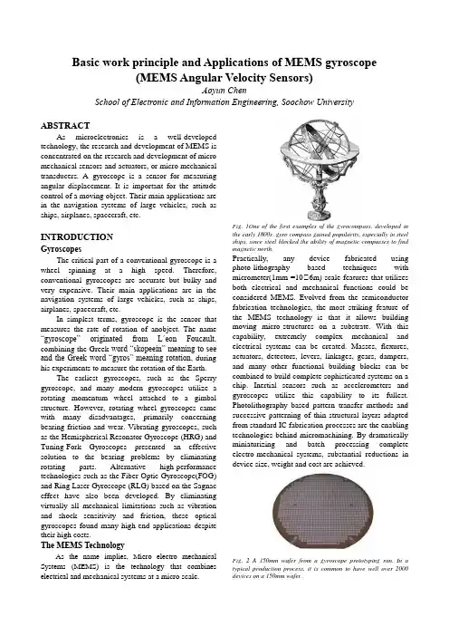
Basic work principle and Applications of MEMS gyroscope(MEMS Angular Velocity Sensors)Aoyun ChenSchool of Electronic and Information Engineering, Soochow University ABSTRACTAs microelectronics is a well-developedtechnology, the research and development of MEMS isconcentrated on the research and development of micromechanical sensors and actuators, or micro mechanicaltransducers. A gyroscope is a sensor for measuringangular displacement. It is important for the attitudecontrol of a moving object. Their main applications arein the navigation systems of large vehicles, such asships, airplanes, spacecraft, etc.INTRODUCTIONGyroscopesThe critical part of a conventional gyroscope is a wheel spinning at a high speed. Therefore, conventional gyroscopes are accurate but bulky and very expensive. Their main applications are in the navigation systems of large vehicles, such as ships, airplanes, spacecraft, etc.In simplest terms, gyroscope is the sensor that measures the rate of rotation of anobject. The name “gyroscope” originated from L´eon Foucault, combining the Greek word “skopeein” meaning to see and the Greek word “gyros” meaning rotation, during his experiments to measure the rotation of the Earth.The earliest gyroscopes, such as the Sperry gyroscope, and many modern gyroscopes utilize a rotating momentum wheel attached to a gimbal structure. However, rotating wheel gyroscopes came with many disadvantages, primarily concerning bearing friction and wear. Vibrating gyroscopes, such as the Hemispherical Resonator Gyroscope (HRG) and Tuning-Fork Gyroscopes presented an effective solution to the bearing problems by eliminating rotating parts. Alternative high-performance technologies such as the Fiber-Optic Gyroscope(FOG) and Ring Laser Gyroscope (RLG) based on the Sagnac effect have also been developed. By eliminating virtually all mechanical limitations such as vibration and shock sensitivity and friction, these optical gyroscopes found many high-end applications despite their high costs.The MEMS TechnologyAs the name implies, Micro electro mechanical Systems (MEMS) is the technology that combines electrical and mechanical systems at a micro scale. Fig. 1One of the first examples of the gyrocompass, developed in the early 1800s. gyro compass gained popularity, especially in steel ships, since steel blocked the ability of magnetic compasses to find magnetic north.Practically, any device fabricated using photo-lithography based techniques with micrometer(1mm =106m) scale features that utilizes both electrical and mechanical functions could be considered MEMS. Evolved from the semiconductor fabrication technologies, the most striking feature of the MEMS technology is that it allows building moving micro-structures on a substrate. With this capability, extremely complex mechanical and electrical systems can be created. Masses, flexures, actuators, detectors, levers, linkages, gears, dampers, and many other functional building blocks can be combined to build complete sophisticated systems on a chip. Inertial sensors such as accelerometers and gyroscopes utilize this capability to its fullest. Photolithography based pattern transfer methods and successive patterning of thin structural layers adapted from standard IC fabrication processes are the enabling technologies behind micromachining. By dramatically miniaturizing and batch processing complete electro-mechanical systems, substantial reductions in device size, weight and cost are achieved.Fig. 2 A 150mm wafer from a gyroscope prototyping run. In a typical production process, it is common to have well over 2000devices on a 150mm wafer.Micromachined Vibratory Rate Gyroscopes Even though an extensive variety of micromachined gyroscope designs and operation principles exist, majority of the reported micromachined gyroscopes use vibrating mechanical elements to sense angular rate. The concept of utilizing vibrating elements to induce and detect Coriolis force presents many advantages by involving no rotating parts that require bearings and eliminating friction and wear. That is the primary reason why vibratory gyroscopes have been successfully miniaturized by theuse of micromachining processes, and have become an attractive alternative to their macro-scale counterparts. The fundamental operation principle of micromachined vibratory gyroscopes relies on the sinusoidal Coriolis force induced due to the combination of vibration of a proof-mass and an orthogonal angular-rate input. The proof mass is generally suspended above the substrate by a suspension system consisting of flexible beams. The overall dynamical system is typically a two degrees-of-freedom (2-DOF) mass-spring-damper system, where the rotation-induced Coriolis force causes.Applications of MEMS GyroscopesAs their performance keeps constantly improving in time, micromachined gyroscopes are becoming a viable alternative to expensive and bulky conventional inertial sensors. High-performance angular rate sensors such as precision fiber-optic gyroscopes, ring laser gyroscopes, and conventional rotating wheel gyroscopes are usually too expensive and too large for use in most emerging applications.With micromachining processes that allow batch production of micro-electro-mechanical systems on a chip similar to integrated circuits, unit costs unimaginable in any other technology are achieved. Moreover, advances in the fabrication techniques that allow electronics to be integrated on the same silicon chip together with the mechanical sensor elements provide an unmatched integration capability. Consequently, miniaturization of vibratory gyroscopes with innovative micro-fabrication processes and gyroscope designs is already becoming an attractive solution to current inertial sensing market needs, and even opening new market opportunities.With their dramatically reduced cost, size, and weight, MEMS gyroscopes potentially have a wide application spectrum in the aerospace industry, military, automotive and consumer electronics markets. The automotive industry applications are diverse, including advanced automotive safety systems such as electronic stability control (ESC), high performance Fig. 3 A packaged MEMS gyroscope chip. The threedimensional micro-scale structure is formed out of single-crystal silicon on a silicon substrate, complete with moving proof-masses, suspension beams, actuators and detectors.navigation and guidance systems, ride stabilization, roll-over detection and prevention, and next generation airbag and brake systems. A wide range of consumer electronics applications with very high volumes include image stabilization in digital cameras and camcorders, virtual reality products, inertial pointing devices, and computer gaming industry. Miniaturization of gyroscopes also enable higher-end applications including micro-satellites, microrobotics, and even implantable devices to cure vestibular disorders.Work principle of MEMS GyroscopeThe Coriolis EffectThe Coriolis effect, which defies common sense and intuition, has been observed but not fully understood for centuries. Found on many archaeological sites, the ancient toy spinning top (Figure 1.1) is an excellent example that the Coriolis effect was part of the daily life over three thousand years before Gaspard Gustave Coriolis first derived the mathematical expression of the Coriolis force in his paper “M´emoire sur les ´equations du mouvement relatif des syst´emes de corps” [1] investigating moving particles in rotating systems in 1835.The Coriolis effect arises from the fictitious Coriolis force, which appears to act on an object only when the motion is observed in a rotating non-inertial reference frame. The Foucault pendulum (Figure 1.2) demonstrates this phenomenon very well: When a swinging pendulum attached to a rotating platform such as earth is observed by a stationary observer in space, the pendulum oscillates along a constant straight line. However, an observer on earth observes that the line of oscillation processes. In the dynamics with respect to the rotating frame, the precession ofthependulum can only be explained by including the Coriolis force in the equations of motion.Coriolis force in linear vibratory rate gyroscope The most basic implementation for a micromachined vibratory rate gyroscope is a single proof mass suspended above the substrate. The proof mass is supported by anchored flexures, which serve asthe flexible suspension between the proof mass and the substrate, making the mass free to oscillate in two orthogonal directions - the drive and the sense directions (Figure 4a).The drive-mode oscillator is comprised of the proof-mass, the suspension system that allows the proof-mass to oscillate in the drive direction, and the drive-mode actuation and feedback electrodes. The proof-mass is driven into resonance in the drive direction by an external sinusoidal force at the drive-mode resonant frequency.The sense-mode accelerometer is formed by the proof-mass, the suspension system that allows the proof-mass to oscillate in the sense direction, and the sense-mode detection electrodes. When the gyroscope is subjected to an angular rotation, a sinusoidal Coriolis force at the frequency of drive-mode oscillation is induced in the sense direction.The Coriolis force excites the sense-mode accelerometer, causing the proof-mass to respond in the sense direction. This sinusoidal Coriolis response is picked up by the detection electrodes. For a generic z-Axis gyroscope, the proof mass is required to be free to oscillate in two orthogonal directions: the drive direction (x-Axis) to form the vibratory oscillator, and the sense direction (y-Axis) to form the Coriolis accelerometer. The overall dynamical system becomes simply a two degrees-of-freedom (2-DOF) massspring- damper system (Fig. 4b).a) b)Fig. 4a A generic MEMS implementation of a linear vibratory rate gyroscope. A proof-mass is suspended above a substrate using a suspension system comprised of flexible beams, anchored to the substrate. One set of electrodes is needed to excite the drive-mode oscillator, and another set of electrodes detects the sense-mode response. 4b A vibratory rate gyroscope is comprised of a proof mass which is free to oscillate in two principle orthogonal directions: drive and sense.a)b)Fig. 5a Torsional gyroscope by Bosch, with a drive mode about the z-Axis. SEM courtesy of Bosch. 5b simplified schematic of torsional gyroscopeCoriolis in torsional gyroscopeGimbals are commonly used in torsional gyroscope suspension systems to decouple the drive and sense modes, and to suppress undesired modes. Many suspension system and gimbal configurations are possible in torsional vibratory gyroscopes. Similar to linear gyroscope systems, the suspension system that supports the masses and gimbals usually consists of thin flexible beams, formed in the same structural layer as the proof-mass.An example gimbal system for a z-Axis torsional gyroscope based on [97] was shown in Figure 4.23. In the drive-mode, the outer drive gimbal is excited about the x-axis. In the presence of an angular rate input about z-axis, the sinusoidal Coriolis torque is induced about the y-axis, which causes the sense-mode response of the inner mass (Figure 5a).A representative gimbal implementation in y-Axis torsional gyroscopes based on [99] is presented in Figure 4.25. The system consists of an inner gimbal that can deflect torsionally in-plane about the z-Axis, and an the outer mass attached to the inner gimbal. The drive-mode is in-plane about the z-Axis, and the sensemode is out-of-plane about the x-Axis. In the drive-mode, the inner gimbal and the outer mass oscillate together, and the angular rate input about the y-Axis generates a Coriolis torque about the x-Axis. The outer mass responds to the Coriolis torque by deflecting torsionally about the x-Axis relative to the drive gimbal. The sensemode response is detected by the out-of-plane electrodes located underneath the outer mass structure.REFERENCES[1] P. M. Whelan, M. J. Hodgon, Essential Principles of Physics, J.W. Arrowsmith Ltd.Bristol, 1978[2] F. M. White, "Viscous Fluid Flow", McGraw-Hill Book Company, 1974[3] Analysis and Design Principles of MEMSDevices,Minghang Bao.。
Crystallographic properties of KSr2Nb5O15Silvania Lanfredi1,*,Celso X.Cardoso,Marcos A.L.NobreFaculdade de Cieˆncias e Tecnologia–FCT,Universidade Estadual Paulista–UNESP,C.P.467,CEP:19060900,Presidente Prudente,SP,BrazilAbstractNanostructured KSr2Nb5O15oxide was synthesized by the polymeric precursor method,a chemical synthesis route based on the Pechini’s method.The X-ray diffraction(XRD)pattern of the calcined powder at11508C were performed in the angular range52u1208with a 0.028step and afixed counting time of30s.The XRD data were analyzed by the Rietveld refinements using the FullProf software.The results showed a tetragonal system with the tetragonal tungsten bronze structure(TTB)type(a=12.4585(2)A˚and c=3.9423(6)A˚,V=611,90 (2)A˚3).In this work,the sites occupancy by the K+and Sr2+cations on the TTB type structure were determined.The thermal parameters(B) were analyzed.#2004Elsevier B.V.All rights reserved.Keywords:KSr2Nb5O15;Chemical synthesis;Tetragonal tungsten bronze;Rietveld method1.IntroductionFrom ferroelectricity discovery and related properties in BaTiO3in1945[1],a large amount of research has been addressed to ferroelectric oxides,in the search by new materials and properties for technological applications.High performance dielectric ceramics act as a key materials for resonators and temperature compensated capacitors.Some ferroelectric polycation oxides are also very important due to the microwave telecommunications progress involving satellite broadcasting and other related devices[2,3].Inten-sive technological research on the next generation of wire-less telecommunications devices has revealed a lack of proper materials for use in new electronic elements and devices.This lack of advanced materials represents a chal-lenge to development of the next generation of materials for microwave application.Although this problem is widely understood,there is still an insignificant interaction between electronic engineers and their materials science counter-parts,which would significantly enhance the progress in this field.In some cases,industrial requirements are not fully recognized by non-industrial segments due to an absent of significant level of communication and analysis of import-specific details of this research area.An among ferroelectric oxides,especially some oxides with the tetragonal tungsten bronze structure(TTB)type are in forefront both in the area of research as well as in industrial applications.Taking into account TTB structure type,a wide variety of cations substitution is possible due the presence of several inter-stices called A,B,and C,respectively[4-6].The tetragonal tungsten bronze-type structure can be considered as a deri-vative of the classical perovskite one.The crystal structure of the TTB-phase is shown in Fig.1[7].It can be described by the chemical formula(A1)2(A2)4C4Nb10O30.A1,A2, and C denote different sites in the crystal structure.The A1 cavities have a cuboctahedral coordination of oxygen atoms, the A2cavities a pentacapped pentagonal prismatic,and the C cavities a tricapped trigonal prismatic one.The size of these cavities decreases in the order A2>A1>C.TTB type compounds,alkaline and/or alkaline-earth metals are located in the A1and A2sites,while only small cations like Li are found in the C site[8].TTB-type compounds with A6Nb10O30formulae,with A=Sr,Ba, are semiconductors containing niobium ions.One possible reason for the semiconducting behavior of these compounds may be the low electron concentration compared to the metallic Na4.5W10O30.However,the increase of the number/locate/msebMaterials Science and Engineering B112(2004)139–143 *Corresponding author.E-mail address:silvania@prudente.unesp.br(nfredi).1Member of the UNESP/CVMat–Virtual Center of Research inMaterials.0921-5107/$–see front matter#2004Elsevier B.V.All rights reserved.doi:10.1016/j.mseb.2004.05.021of charge carries is possible by replacing of divalent alkaline earth cations with trivalent lanthanoids,in according to M 2þ6Àx Ln 3þx Nb 10O 30.The distribution of metal cations in different interstices can improve physical properties,such as electro-optic,nonlinear,elasto-optic and pyroelectric properties [9].These properties depend on the morphology of the specimen and the method of synthesis.Alkali-metal niobate powders are typically prepared via solid-state reaction using alkali-metal carbonate and nio-bium oxide as starting materials [10].However,this tradi-tional method does not always lead to a homogeneous mixture of compounds.Process of grinding and regrinding are typically necessary.This preparation process involves several restrictions to powder features being all one inherent to this processing technique.As an example,metastables intermediate phases can be found when powders are pre-pared by conventional methods.Furthermore,high calcina-tions and sintering temperatures are required to complete the synthesis reaction and densi fication due the low surface area of raw and products powders,respectively.Indeed,this method does not always allow the production of homoge-neous single-phase ceramics.Otherwise,oxides synthesis based on the chemical methods lead to simultaneous improve-ment of several chemistry and physic parameters such as stoichiometry,texture control,chemical homogeneity and single phase.A wide range of chemical routes adequate to the powder synthesis has been developed for preparing of niobate.Coprecipitation and sol-gel processes are the most common chemical routes [11,12].Another interesting methods to prepare ceramic powders have been described elsewhere,such as the polymeric pre-cursor method [13-16],the wet chemical method using a water-soluble malic acid complex [17]and hydrothermal synthesis [18].It is interesting to note that a major part ofchemical synthesis methods exhibit a great potential to prepare reliable solid solutions involving signi ficant rela-tives fractions of cations of alkali metal or another doping one.In general,few studies on the electrical,dielectrical and structural properties have been addressed to the KSr 2Nb 5O 15system of TTB type structure.Furthermore,in several studies reported elsewhere,oxides belong to the TTB sys-tems have been prepared by conventional method.In this work,the KSr 2Nb 5O 15single phase powder was synthesized by a chemical method based on the Pechini ’s method termed Polymeric Precursor method.The powder was characterized by X-ray diffractions.The crystallographic parameters,as unit cell and atomic parameters,of the KSr 2Nb 5O 15powder with TTB type structure were re fined from the Rietveld method.2.Experimental2.1.Synthesis procedurePolymeric precursor method has been successfully used to synthesize nanometric [15,19]and nanostructured pow-ders [15,19,20]depending on the calcinations temperature.Typically,nanometric particles exhibit amorphous character on the XRD analysis [15].Further crystallinity degree is attained at more higher calcinations temperature,which is accomplished of particle growth [15,20].As a function of particle growth,the development of nanostructures occurs [20].KSr 2Nb 5O 15single phase powder was synthesized by the polymeric precursor method (PPM)a route of chemical synthesis based on the method developed by Pechini [21].As a whole,this method gives rise a better control of reagents,a low calcination temperature,a single phase material and powder with high speci fic surface area.The starting reagents for the powder synthesis via che-mical route were citric acid H 3C 6H 5O 7ÁH 2O (99.5%reagent),ethylene glycol HOCH 2CH 2OH (98.0%Synth)and niobium ammonium oxalate NH 4H 2[NbO(C 2O 4)3]Á3H 2O (CBMM-Brazil),strontium nitrate Sr(NO 3)2(99.5%)and potassium oxalate K 2C 2O 2ÁH 2O (99.5%).The ratio among of chelating agents used was 3mole of citric acid for each mol of metallic cations to be chelated.The ratio between citric acid and ethylene glycol is given in weight percentage,for a solution of 60%in weight of citric acid,40%in weight of ethylene glycol was used.Citric acid was dissolved in ethylene glycol at 908C,while the solution was continuously stirred in a beaker.In the sequence,each salt was dissolved.Due to the slow rate of solubilization of NH 4H 2[NbO(C 2O 4)3]Á3H 2O in the ethylene glycol/citric,100ml of distilled water was added,which promotes a fast salt solubilization.After com-plete dissolution of salts,a colorless and translucent solu-tion was achieved being the temperature raised to 1408C promoting the polyester formation.After the polyesteri fica-tion reaction,a polymeric gel is obtained.The polymer isnfredi et al./Materials Science and Engineering B 112(2004)139–143140Fig.1.Schematic representation of the tetragonal tungsten bronze structure (TTB).maintained in the beaker undergoes a primary calcination in a furnace type box at3508C during3h.This process leads to the partial polymer decomposition forming a puff or expanded resin,which consists in a brittle reticulated mate-rial.As a function of gases emanation(CO,CO2and H2O) and O2consume,an atmosphere renovation of the furnace should be guaranteed.This material was deagglomerate (350mesh)in an agate mortar being termed precursor.This brittleness material was ball milled in a polypropy-lene jar using as grinding media zircon balls during10h in isopropyl alcohol.Thus,the material was dry in a grove box with forced air circulation at508C and deagglomerate in agate mortar at a350mesh minimum.The precursor was calcined in a tube furnace with integral oxygen atmosphere. An oxygenflux of300ml/min was maintained during a complete thermal cycle,heating cycle and cooling cycle. The heating cycle was carried out via two calcination steps.From room temperature,the temperature was increased using a heating rate equal to10o C/min up to3508C;at this point the temperature was kept constant during3h.In the sequence,the same heating rate was used being the tem-perature increased at11508C being maintained during10h. After this cycle,the furnace was cooling to the natural rate. The oxygenflux was maintained constant at300ml/min during the cooling cycle.2.2.X-ray instrumentation and analysisThe powder obtained from calcination of the precursor in oxygen atmosphere was characterized by X-ray diffraction (XRD).A diffractometer with Cu K a radiation(l=1.54A˚) and a graphite monochromator were used.Measurements were carried in the angular range582u1208,the scanning step of0.028andfixed counting time of30s.The diffraction pattern is refined in according to the Rietveld method.The refinement was performed using the program Fullprof[22]. The parameters and variables adopted during the refinement process are the background coefficients,profile coefficients, histogram scale,lattice parameters,linear absorption coeffi-cients,coordination parameters or oxygen parameters(X)and isothermal parameters for four kinds of atoms(K,Sr,Nb and O).The background level wasfitted with afive-order poly-nomial function and the peak shape with a pseudo-V oigt function.The tetragonal tungsten bronze niobate synthesized was identified from the JCPDS card number34-0123.The thermal stability and properties were investigated by differential thermal analysis(DTA)and differential scanning calorimetry(DSC).The measurements were carried out in air atmosphere at heating rate equal to108C/min,in the temperature range fromÀ1008C to5008C for DSC analysis and from room temperature up to12008C for DTA analysis. In both thermal analysis none endothermic or exothermic phenomenon was detected.The physical and chemical behavior observed suggest a great thermal stability of the KSr2Nb5O15powder prepared,in according to previous procedure and parameters of preparing.3.Results and discussionX-ray diffraction profile showed the formation of the KSr2Nb5O15TTB with single phase and crystalline char-acteristic.The Rietveld method was used to determine the set of crystallographic parameters of the KSr2Nb5O15 oxide synthesized by chemical route.Table1shows the initial atomic parameters of the proposed structure for thenfredi et al./Materials Science and Engineering B112(2004)139–143141Table1Atomic coordinates,isotropic thermal parameters B(A˚)and relativeoccupancies PAtoms Wyckoffpositionx y z B PSr(1)2a000.008(6)0.59(10)0.25K(2)4c0.1718(4)0.6718(5)À0.0209(7) 2.75(3)0.25Sr(2)4c0.1718(4)0.6718(5)À0.0209(7) 2.75(3)0.25Nb(1)2b01/21/20.74(4)0.25Nb(2)8d0.0762(3)0.2133(3)0.4768(4)0.10(6)1O(1)8d0.1568(2)0.0696(3)0.5399(7)0.04(5)1O(2)8d0.3489(3)0.0067(10)0.5339(8)0.07(5)1O(3)8d0.0731(3)0.2072(9)0.0235(7)0.07(5)1O(4)4c0.2842(3)0.7827(9)0.3973(11)0.07(5)0.5O(5)2b01/2À0.101(12)0.07(5)0.25Table2Structural data of the KSr2Nb5O15TTB niobate synthesized by chemicalrouteCrystallographic dataFormula KSr2Nb5O15Crystal system TetragonalSpace group P4bm(No.100)a(A˚)12.4585(2)c(A˚) 3.9423(6)V(A˚)611.90(2)Z2Molecular weight918.79Data collectionTemperature(8C)24Wavelength[Cu K a](A˚) 1.5418Monochromator GraphiteMeasuring range(8)52u120Step(82u)0.02Integration time(s)30Rietveld dataProgram FULLPROFNumber of independent reflections290Number of independent parameters46Function for background level Polynomial5-orderFunction for peak shape(H2=U tan2u+V tan u+W)Pseudo-V oigtU0.0530(4)V0.0230(2)W0.0160(4)R Bragg(%) 6.02R F(%) 4.28c R p(%)13.0c R wp(%)16.1x2 2.98re finement,as well as the isotopic thermal parameters and relative occupancies.Fig.2shows the Rietveld graphic for the KSr 2Nb 5O 15with the observed and calculated X-ray diffraction as well as their difference.On it are represented the observed curve that was obtained by X-ray diffraction (spotted curve)and derived curve (continuous lines).The residual curve and the positions of the peaks (marked by small bars)are shown below.The residual pattern shows that there is a good match between the theoretical and observed X-ray patterns,noted by the small variation along the diffraction angle.The X-ray diffraction pattern obtained was indexed on the basis of a tetragonal unit cell.From observed re flections,there is only evidence of the rule existence [(0,k ,l )k =2n ],which is compatible with space groups P 4bm ,and P 4/mbm .The re finements were performed taking in account the centro-symmetric space group P 4bm .Powder data and experimen-tal conditions are listed in Table 2.The best theoretical adjust were obtained supposing each pentagonal A site (site 4c (x ,x +1/2,z ))statistically occupied by equal quantities of K +and Sr 2+ions and each square B site (site 2a (0,0,z )occupied by Sr 2+ion,as shown in Table 1.KSr 2Nb 5O 15is a ferroelectric material with a Curie temperature at around 430K at 103Hz.In fact,ferroelectric polarization is sup-posed to be due to D z (Nb displacement from its position in the paraelectric phase,at least for displacive ferroelectric.The value of z (coordinate of Nb (2)in 8j sites)is different from z =1/2.In addition,the highly covalent Nb –O bonds ensure a long-range dipolar interaction within the ferro-electric domains and lead to a classical ferroelectric beha-vior [23].R Bragg ,R F ,R p and R wp index values obtained from re finement of the KSr 2Nb 5O 15system,as well as the unitary cell parameters and the volume V are shown in Table 2.The R p index,R p ¼f P W i ðY i o ÀY i c Þ2=P W i Y i o 2Þg 1=2where W i is the weight assigned at each intensity step,indi-cates the agreement between the structure model adopted and the real one.The R wp index,R wp P j Y i o ÀY i c j =P Y i owhere Y i o and Y i care the observed and calculated intensities,respectively,indicates the quality of the re finement.All the re finement indexes obtained for the KSr 2Nb 5O 15are con-sidered very good.The unit cell parameters derived for KSr 2Nb 5O 15were:a=12.4585(2)A˚,c =3.9423(6)A ˚and the volume V cell =611.90(2)A˚3.These values are in accordance with one published previously,which was prepared from the conven-tional method (mechanical mixture of oxides/carbonates)with thermal treatment at high temperature (1300–15008C and 10–30h of thermal treatment).Comparison between the data of this work with one publishing elsewhere [24]showed that the KSr 2Nb 5O 15oxide obtained in this work,exhibits a minor isotropic thermal parameter B value with relation to one of the KSr 2Nb 5O 15oxide prepared by con-ventional method [24].Since B parameter is connected tonfredi et al./Materials Science and Engineering B 112(2004)139–143142Fig.2.Rietveld graphic for KSr 2Nb 5O 15synthesized by chemical route.order–disorder degree,a more higher B value suggests some superior disorder degree in the structure[25].Then,it is possible to hypothesize that KSr2Nb5O15oxide synthesized in this work exhibits a small static disorder in the grain interiors and/or grain boundary regions.This feature is compatible with process of rearrangement and growing up of crystallites from sintering phenomenon of the nanostruc-tures[15,19,20].Based on the natural development sequence of particles considering the method of synthesis used in this work,i.e.nanoparticles!nanostructures!submicro-metric particles!micrometric particles,it seems that continuous defragmentation of crystallites and eventual annihilation of disordered domains can be connected with enhancement of order aspects at least during high tempera-ture treatment.Some kind of order retrieving has been reported after thermal annealing of disordered material,in which a disorder degree has been created by mechanical refinement in crystallite size[26].4.ConclusionThe chemical synthesis based on Pechini’s method showed an adequate method to prepare KSr2Nb5O15single phase with controlled stoichiometry.In addition,KSr2Nb5-O15crystalline powder was obtained at lower temperature than one prepared by conventional mixture of oxides.The Rietveld refinement showed that the KSr2Nb5O15TTB type structure presents a space group compatible with P4bm and each pentagonal A site is statistically occupied by equal quantities of K+and Sr2+ions and each square B site is occupied by Sr2+ion.AcknowledgementsThis work was supported by the Brazilian research funding institutions FAPESP.The authors wish to acknowl-edge Prof.P.Gravereau for training on the Rietveld method analysis and Dr.S.Pechev for help in the manipulation of the Fullprof program,and the CBMM-Brazil for providing the niobium salt.References[1]B.Wul,L.M.Goldman,C.R.Acad.Sci.URSS46(1945)139.[2]D.Kolar,S.Glaberscek,Z.Stadler,D.Suvorov,Ferroelectrics27(1980)269.[3]X.M.Chen,Y.Suzuki,N.Sato,J.Mater.Sci:Mater.Electron.5(1994)244.[4]P.R.Slater,J.T.S.Irvine,Solid State Ionics124(1999)61.[5]K.Tatsumi,M.Hibino,T.Kudo,Solid State Ionics96(1997)35.[6]B.Tribotte´,J.M.Haussonne,G.Desgardin,J.Eur.Ceram.Soc.19(1999)1105.[7]A.Magneli,Ark.Kemi1(1949)269.[8]S.C.Abrahams,P.B.Jamieson,J.L.Bernstein,J.Chem.Phys.54(1971)2355.[9]N.Wakiya,J.K.Wang,A.Saiki,K.Shinozaki,N.Mizutani,J.Eur.Ceram.Soc.19(1999)1071.[10]C.L.Wang,Y.G.Wang,P.L.Zhang,W.L.Zhong,H.S.Zhao,SolidState Comm.85(1993)331.[11]nfredi,L.Dessemond,A.C.M.Rodrigues,J.Eur.Ceram.Soc.20(2000)983.[12]M.A.L.Nobre,nfredi,Catal.Today78(2003)529.[13]M.A.L.Nobre,nfredi,J.Appl.Phys.93(2003)5576.[14]M.A.L.Nobre,nfredi,Appl.Phys.Lett.81(2002)451.[15]M.A.L.Nobre,E.Longo,E.R.Leite,J.A.Varela,Mater.Lett.28(1996)215.[16]M.A.L.Nobre,nfredi,Appl.Phys.Lett.82(2003)2284.[17]E.R.Camargo,M.Kakihana,Solid State Ionics151(2002)413.[18]I.C.M.S.Santos,L.H.Loureiro,M.F.P.Silva, A.M.V.Cavaleiro,Polyedron21(2002)2009.[19]R.C.R.Franco,E.R.Camargo,M.A.L.Nobre,E.R.Leite,E.Longo,J.A.Varela,Ceram.Int.25(1999)455.[20]E.R.Leite,M.A.L.Nobre,M.Cerqueira,E.Longo,J.A.Varela,J.Am.Ceram.Soc.80(1997)2649.[21]M.P.Pechini,US Patent No.3.330.697(1967).[22]J.Rodrigues-Carvajal,Collected Abstracts of Powder DiffractionMeeting,Toulouse,France,1990,p.127.[23]S.C.Abrahams,S.K.Kurtz,P.B.Jamieson,Phys.Rev.172(1968)551.[24]H.A.Belghiti,A.Simon,P.Gravereau,A.Villesuzanne,M.Elaatmani,J.Ravez,Solid State Sci.4(2002)933.[25]P.Chatterjee,S.P.Sen-Gupta,Appl.Surf.Sci.182(2001)372.[26]X.Gao,J.Xue,T.yu,Z.Shen,J.Whang,J.Am.Ceram.Soc.85(2002)833.nfredi et al./Materials Science and Engineering B112(2004)139–143143。
实验Experiment P58:Light Intensity inDouble-Slit and Single-Slit DiffractionPatterns双缝和单缝衍射斑的光强Concept: interference 概念:干涉,衍射Time: 45 m 时间:45分钟SW Interface: 500,700 or 750科学工作室接口:500,700或750 Macintosh file: P58 Diffraction Patterns Windows file:EQUIPMENT NEEDED 所需仪器1. Science Workshop Interface科学工作室接口2. Light Sensor CI-6504A 光传感器 CI-6504A3. Rotary Motion Sensor (RMS) CI-6538 旋转运动传感器 CI-6538(RMS)4. Slit Accessories OS-8523 单缝,双缝和多缝5. Laser OS-8525 激光器6. Aperture Bracket OS-8534 光传感器支架7. Linear Translator OS-8535 线性运动附件(用于RMS)8. 1.22 m Optics Track 1.22米光轨PURPOSE 目的The purpose of this laboratory activity is to investigate the wave nature of light by studying diffraction patterns. 本实验的目的是通过衍射斑研究光的波动性。
Theory: Part One 理论:第一部分In 1801, Thomas Young obtained convincing evidence of the wave nature of light. Light from a single source falls on a slide containing two closely spaced slits. If light consists of tiny particles (or “corpuscles” as described by Isaac Newton), we might expect to see two bright lines on a screen placed behind the slits. Young observed a series of bright lines. Young was able to explain this result as a wave interference phenomenon. Because of diffraction, the waves leaving the two small slits spread out from the edges of the slits. This is equivalent to the interference pattern of ripples produced when two rocks are thrown into a pond. 1801年,Thomas Young获得了光具有波动性的有力证据。

多发性硬化实验动物模型研究进展陈永妍;李林;张旗;尹琳琳【摘要】多发性硬化实验动物模型可模拟人类该病的不同类型或不同阶段,是研究该病病因和研发治疗药物的有效工具.【期刊名称】《基础医学与临床》【年(卷),期】2013(033)011【总页数】4页(P1500-1503)【关键词】多发性硬化;动物模型;自身免疫;髓鞘多肽;病毒;神经毒素【作者】陈永妍;李林;张旗;尹琳琳【作者单位】首都医科大学宣武医院药物研究室北京市老年病医疗研究中心神经变性病教育部重点实验室,北京100053;郑州大学药学院,河南郑州450001;首都医科大学宣武医院药物研究室北京市老年病医疗研究中心神经变性病教育部重点实验室,北京100053;郑州大学药学院,河南郑州450001;首都医科大学宣武医院药物研究室北京市老年病医疗研究中心神经变性病教育部重点实验室,北京100053【正文语种】中文【中图分类】R744.5+1多发性硬化(multiple sclerosis,MS)属中枢神经系统(central nervous system,CNS)炎性反应脱髓鞘疾病,是CNS脱髓鞘疾病的典型代表[1-2]。
目前多发性硬化的发病机制尚不明确,较为公认的学说是病原体侵入机体引发异常的自身免疫反应所致[3]。
由于神经组织取样的局限性,为了获得疾病不同方面的信息,采用动物模型模拟MS的病理改变和临床特征是十分必需和必要的。
1 髓鞘多肽片段诱导的MS动物模型实验性自身免疫性脑脊髓炎模型(experimentally allergic encephalomyelitis,EAE)是一种以特异性致敏的CD4+和CD8+T细胞介导为主的,以中枢神经系统内小血管周围出现单核细胞浸润及髓鞘脱失为特征的自身免疫疾病,是人类多发性硬化经典的实验动物模型[4]。
致脑炎物质能够诱发实验性自身免疫性脑脊髓炎模型(experimentally allergic encephalomyelitis,EAE)[5],这些物质主要包括髓鞘碱性蛋白(myelin basic protei,MBP)、蛋白脂质蛋白(proteolipid protein,PLP)、髓磷脂少突胶质细胞糖蛋白(myelin oligodendrocyte glycop rotein,MOG)或合成的能够替代上述蛋白的多肽序列。
532PDA Pigtailed Photodiode SpecificationsAbsolute Maximum RatingsAbsolute maximum limits mean that no catastrophic damage will occur if the product is subjected to these ratings for short periods, provided that each limiting parameter is in isolation and all other parameters have values within the performance specification. It should not be assumed that limiting values of more than one parameter can be applied to the product at the same time.Parameter Symbol Minimum Maximum Units Reverse Voltage Vr-20V Reverse Current Ir-1mA Forward Voltage Vf-1V Forward Current If-5mA Power Dissipation--50mW Operating Temperature Tc–40+85°C Storage Temperature Ts–40+85°C Soldering – 10 seconds--+260°C Fiber Pull--10NPerformance SpecificationsTest Conditions:Unless Otherwise Stated PDA2446 Parameter Symbol Vr = 5 V, Tc = +25°C Min.Max.Units Dark Current Id-1nATc= +85°C-50nA Reverse Breakdown Voltage Vbr Ir = 10 µA35-V Capacitance C 1 MHz- 1.7pF Responsivity Rλ = 1300 nm0.7-A/W Operating Wavelengthλ80% points12001650nM Small Signal Bandwidth Bw 1.5-GHz Linearity X1Second Order-Vr = 15 V-70dBcfl = 135 MHzf2 = 190 MHz70% Modulation0 dBm Optical PowerThird Order-As above-85dBcFiber Pigtail: Tight jacketed, self-mode stripping, singlemode fiberParameter Minimum Maximum Units Length 1.0-mCore Diameter810µmCladding Diameter122128µmConcentricity Error-8%Secondary Jacket Diameter0.8 1.0mm533PDA Mechanical Outline OptionsALL DIMENSIONS IN MILLIMETERSPDA2446-DALL DIMENSIONS IN MILLIMETERS PDA2446 Electrical Pin-OutsPIN 1: CATHODE +VEPIN 2: CASEPIN 3: ANODE –VE534Ordering InformationPDA2446-XI-XXConnector Type:AP = Angle Polished FC/PCAS = Angle Polished SC/PCUS = Ultra Polished SC/PCSF = Super Polished FC/PCFlange Type:B = BarrelD = 2 hole PCB mount, 12.7 mm between centersAdditional options are available to meet your specific needs. Please contact your local representative for details.535536537Performance Specifications Absolute Limiting RatingsAbsolute (limiting) ratings mean that no catastrophic damage will occur if the product is subjected to these ratings for short periods, provided that each limiting parameter is in isolation and all other parameters have values within the performance specification. It should not be assumed that limiting values of more than one parameter can be applied to the product at the same time.ParameterSymbol MinimumMaximumUnits Supply VoltageV DD - 5.5V Photodiode Voltage (Negative)V pin -–7V Power Dissipation--350mW Operating Temperature Tc –40+85°C Storage Temperature Ts –40+85°C Soldering – 10 seconds --+260°C Fiber Pull --10NPerformance Specifications [1]Parameter Minimum MaximumUnits Responsivity 0.75-A/W Sensitivity [2]52 Mb/s –39-dBm 155 Mb/s –36Overload [2,3]–7-dBm Bandwidth 52 Mb/s 35-MHz 155 Mb/s90Output Impedance 3060ohms V DD Supply Voltage 4.75 5.25V V DD Supply Current -50mAPhotodiode Supply–7–4.5VNotes:1. Measured over the operating temperature range and power supply tolerance.2. Measured at the data rate specified for 1 x 10⁻¹⁰ using an infinite extinction ratio laser source modulated with a 223-1PRBS pattern.3. Higher overload performance available. Contact your local Hewlett-Packard Components representative for details.Fiber Pigtail: Tight jacketed, self-mode stripping, multimodeParameter MinimumMaximumUnits Length0.4 1.2m Core Diameter 4753µm Cladding Diameter 122128µm Concentricity Error-8%Secondary Jacket Diameter0.81.0mmSchematic Diagram321. GND 2. V OUT 3. V pin 4. +V DD538Drawing DimensionsPPA0052-FC-A PPA0155-FC-AMIN.––––12.00.27M8 x 0.7513.35A B C ∅D E ∅F ∅G H DIM.MIN.2.08–––– 2.54 NOM.–∅J L M N P ∅Q ∅RDIM.ALL DIMENSIONS IN MILLIMETERSMAX.19.59.515.09.1–0.3313.55MAX.2.321.652.26.88.24.2PPA0052-SC-APPA0155-SC-AMIN.–––––12.0A B C D E FDIM.MIN.2.00.27–2.08 2.54 NOM.17.8G ∅H ∅J ∅K ∅L M DIM.ALL DIMENSIONS IN MILLIMETERSMAX.9.523.013.515.58.0–MAX.3.00.337.52.518.2PPA1052-APPA1155-AMIN.––12.0–0.27400A B C D ∅E FDIM.MIN. 2.54 NOM.––13.352.1–∅G H K L ∅M ∅NDIM.ALL DIMENSIONS IN MILLIMETERSMAX.25.019.5–9.50.331200MAX.9.52.013.552.46.25539Ordering InformationAllowable Part Numbers:PPA0052-XX -A PPA0052 - FC - A PPA0155-XX -APPA0052 - SC - A Receptacle Type:PPA1052 - A - FP FC = FC PPA1052 - A - ST SC = SCPPA1052 - A - DN PPA1052 - A - SC PPA1052-X -XX PPA1052 - D - FP PPA1155-X -XXPPA1052 - D - ST Connector Type:PPA1052 - D - DN FP = FC/PC PPA1052 - D - SC ST* = ST DN = DIN PPA0155 - FC - A SC = SCPPA0155 - SC - A PPA1155 - A - FP Flange Type:PPA1155 - A - ST A = 2 hole Panel mount, 13.4 mm between centers PPA1155 - A - DN D = 2 hole PCB mount, 12.7 mm between centersPPA1155 - A - SC PPA1155 - D - FP PPA1155 - D - ST PPA1155 - D - DN PPA1155 - D - SC*ST is a registered trademark of AT&T.PPA1052-D PPA1155-DMIN.––12.0–0.274002.54 NOM.A B C D ∅EF ∅GDIM.MIN.3.8–0.9 12.7 NOM.2.1––H J K L ∅M ∅N P DIM.ALL DIMENSIONS IN MILLIMETERSMAX.25.018.0–9.50.331200MAX.4.27.51.12.46.257.5。

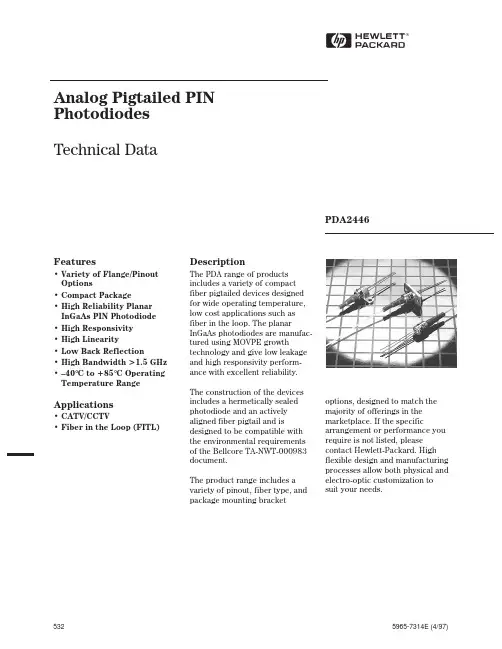
1.Petroleum Tanker Product Range BrochurePetroleum Tanker Product Range 1300 134 651 | .au2.4540SGV 4500 SERIES DROP ADAPTORS 52045204ADBSGF4-255200-SFI-3DROP ELBOWS / ELBOW INLETS6000ASADBFVAO210K1DBFA80DBDT80-2200DBDA80ALDC400DCAL400DC-L DUST CAP AL400DC-L& DUMMY PROBES FT155A FT304A EXTINGUISHERSAPI VALVES3.Petroleum Tanker Product Range Brochure SA4050WD401ALVB TTMA BUTTERFL Y VALVESTTMA FLANGES & ROUND FLANGE GASKETS400-AL T-SSCVRH100FF C1000100FF 5000AIV AIR INTERLOCKS VALVESTUBE DOORS & STEPS TDF7FT451OVERFILL PROBES FT150A FT151DBLWKIT DBCO402DBHSLS HAZCHEM LIBRARY DBVH090DBVR6410114DBSPT K-SERIES ISO-A COUPLINGS K8BF8-GApplications:Installed on the gantry to control the loading process of petroleum fuels or other hazardous liquid into cargo tanks.Features:•Automatically switches between 2-wire or 5-wire type sensors •Compatible with analogue 2-wire thermistor type sensors •Redundant relay outputs prevent single-point failures •Ground verification Approvals:•IECEx Certification •Meets API RP1004 and EN13922 standards •Suitable for Class I, Division 1, Group CD and Class I, Zone 1, Group IIBContact customer service for applicable Rack Cord and Junction Box details.Terminal OverfillTerminal LoadingSwivelsApplications:Combined with API adaptors, these couplers are suitable for rail car and tank truck loading and unloading.Features:•Modular design allows various face seal combinations to be compatible with different alternative fuels, performance levels and applications •Fully interlocked collar prevents fitting from opening when disconnected and from being disconnected while opened •4” TTMA inlet mounting flange connection •Ball-end handle for easy and comfortable operation •No special tools needed for maintenanceMaterials:•Body and Poppet: 356 T6 Aluminium anodized hard-coat •Cam: stainless steel •Seals: FKM-GFL T standard; Baylast™, EPDM, Fluoroelastomer, FKM-B, HiFluor®•Link, shaft, pin, crank: Hardened 17-4PH stainless steel•Handle: Aluminium, stainless steel Applications:Used wherever a leak-proof swivel connection is needed. Industries range from petroleum, petrochemical, fluid and dry bulk transfer and many more.Features:•Full 360° rotational movement •Wide spacing between dual ball bearing raceways ensures greater load-bearing capacity•Radius elbow design ensures a smooth flow pattern•Hydrostatic testing is performed on all swivels•Precision-machine design ensures alignment Materials:•Stainless steel •Steel •AluminiumRack Monitor API Coupler Junction BoxRack Cord Optic AssemblyStyle 30 Swivel Style 30 Long Radius SwivelSplit Flange Swivel5.Petroleum Tanker Product Range Brochure Applications:API Valves are used for bottom loading and unloading of petroleum tankers. Features:• Ergonomically curved handle that opens with a short 62-degree stroke• Fixed or removable handle available• Maintenance can be performed without removing the valve from the tanker • Interchangeable with competitor product made to the same specification • Cast anode connection point to combat galvanic corrosion• Biofuel compatible, up to E100 (Ethanol 10% and B100 - BioDiesel 100%)Materials:• Aluminium body and handle• Anodized hard coat aluminium nose ring• Baylast™, FKM and PTFE seals• Acrylic full-body sight glass• Stainless steel hardwareApprovals:•API RP-1004API ValvesDrop Adaptors Applications:To be used in conjunction with the standard API valve. The gravity drop adaptor features an industry standard API female connection designed to couple directly to the standard API valve leaving either a 3” or 4” male camlock adaptor.Features:• 3” or 4” connections• Quality cast aluminium body• Various seal options available• Drop adaptors have an optional sight glass• Standard one-piece bodyMaterials:• Cast aluminium body• Bronze cam arms•Stainless steel pin and finger ringsLoading ArmApplications:Used for the transfer of liquids and dry bulk materials in refineries, chemical plants, rail terminals, truck terminals, tote and drum filling.Features:• 3 options of sealing swivels: O-ring, v-ring and split flange• Wide variety of end configurations available• Torsion spring counterbalance with steel housing and multiple grease ports • Engineered with easy service in mindMaterials:• Hardened carbon steel, stainless steel and aluminium• Seals: Buna, EPDM, FKM-A and B, PTFE and Baylast™Sizes:• 2”, 3” and 4” API Adaptor Loading Arm Gravity Drop Adaptor without Sight Glass Gravity Drop Adaptor with Sight GlassLocking Dust CapApplications:The side-seal drop elbows provide easy quick connection and disconnection to dischargehoses from a road tanker to a fill point on underground storage tanks, allowing for quick andsafe product transfer. Spring-loaded levers allow the elbows to snap on securely to a sideseal tight fill adaptor with minimal pressure. For use with standard 3” and 4” side seal style fillcollars only.Features:• Modular, easy repair, bolt-on construction• Comes with acrylic sight glass• Buna seals and bronze arms• Choice of 3” or 4” inlets• Available with anti-spill sleeveMaterials:• Body - Aluminium• Levers - Bronze• Sight Glass - Acrylic• Seal - Baylast™Side Seal ElbowFootvalve and AccessoriesFOOTVALVEApplications:Dixon Bayco® emergency valves are designed for use on road tankers to facilitate safe andefficient loading and discharge of tank contents.Features:• Quick action high lift sequentially operated pneumatic ram and can be manually operated• Main body shear groove design and can be easily removed for routine maintenanceMaterials:• Aluminium construction• Stainless steel shaft and roller• Steel springs and fastenersACCESSORIESApplications:Dixon Bayco® Camlifts are designed for use on road tankers specifically where opening andclosing of the emergency valves are required from the tanker walkway.Features:• Manual cam lift assembly with gasket and fasteners• Quick action high lift mechanism ensures maximum emergency valve opening• Designed to interchange with other brands commonly found in the Australian market• Can be mounted directly to tanker walkway or separate weld in flangeProduct indicators are used to display the name of the product in the corresponding tankercompartment.Features:• Mounts directly to 4” TTMA flange• All label colouring is in accordance with SLP recommendations• Diesel - Avgas 100 - ULP + E• Ethanol• Kerosene - Jet A1 - E-85• ULP91 - Hi-Octane - Blank• Supplementary labels availableSide Seal Drop ElbowEmergency FootvalveManual Camlift AssemblyLift Wire Assembly KitProduct IndicatorFemale Elbow InletMale Elbow Inlet7.Product Range Brochure Dixon Bayco ® fill tube and dip tube adaptor kits are designed for use on tanker compartments fitted with dip and fill fittings. Dip and fill tube blank plates are used where tankers are not fitted with fill tubes.Features:• Designed to interchangeable with other brands commonly found in the Australian market• Mounts direct to manholes or tanker walkwaysMaterials:• Aluminium construction• SS Fasteners• Cork/ Buna gasketTTMA ValvesThe butterfly valve is a lightweight and compact quarter-turn in-line stop valve. This versatile valve is widely used for liquid, gaseous or dry products and is available in a variety of sizes and styles.MANUALL Y OPERATED TTMA METERED WET -R-DRI VALVEThe manual metering/locking valve provides an eight-position metering locking handle, which holds the disc in the desired position.MANUALL Y OPERATED TTMA DETENT WET -R-DRI VALVEThe manual detent model provides a positive stop in the open and closed position, as well as a detent spring and ball which assist in holding the disc in the open or closed position.Features:• Can be mounted in any position with the handle located for easy operation• Standard right-hand operation by turning handle quarter turn counter-clockwise and left-hand operation• Bolt pattern matches TTMA piping flange dimensionsMaterials:• Body: Aluminium, cast iron or stainless steel-lined•Disc: FKM-B coatedFill Blanking Plate Dip Tube Guide Steady Dip TubeDip or Fill AdapterMetered Wet-R-Dri Valve Detent Wet-R-Dri ValveFire ProductsApplications:Used on the side of the tanker in case of an emergency, the following products can be found on the tanker:• ABE Extinguishers• Heavy duty Vehicle bracket• Tag for testing• PVC Coated bagABE ExtinguisherPVC Extinguisher Bag Maintenance Record TagHeavy Duty Vehicle BracketHazchem Library (EIP)NozzlesTank Truck OverfillApplications:A large range of nozzles from standard utility automatic and manual shutoff, used for diesel,fuel and AdBlue®.Features:• 3/4” inlets up to 1 1/2” inlets• Colour coded options• Swivels available• Auto shutoffApprovals:• UL listed approvals as applicableMaterials:• Aluminium body• Nylon hose guardApplications:Hazchem library signs (EIP - Emergency Information Panel) are used on vehicles and storagecontainers to display the fact that they are storing or transporting dangerous chemicals orsubstances.Features:• Lightweight• Spring clips on each side to secure in place• Rubber buffer to prevent vibration• Replaceable hinged panels• Capacity to display up to 4 dangerous goods• Stainless steel accessoriesMaterials:• Aluminium constructionFLOTECH™ REPLACEMENT PROBEThe FT150 2-wire probe is electronically and mechanically compatible for drop-inreplacement of commonly used 2-wire probes with black and white wires. The FT150provides the fast response and reliability of optic technology.Features:• Fail-safe self-checking circuits and designed to fail in a no-load mode• Compatible with all 2-wire systems built to the API RP 1004 standard• Prism is sealed with an o-ring to prevent prism leaks• Aluminium and stainless steel flaceplates and probesApprovals:• IECEx CertificationFLOTECH™ SOCKETSFlotech™ sockets allow the transfer of the electronic signal from the terminal control monitorto the tanker and return. Sockets will vary depending upon terminal equipment and regionalregulations.Features:• 4 bayonet-style J-slots fixing to industry standard• 10 pin as standard• Allows for overfill protection with added ground assurance• Sufficient room to easily install and mount dummy probe as required in 2-wire systems Overfill Probe10-Pin 4J SocketPressure Nozzle for Bulk DeliveryDEF Automatic Shutoff Nozzle (ADBLUE)Big Mouth™ Diesel NozzleTruck MonitorHazchem Library9.Petroleum TankerProduct Range BrochureManntek Dry DisconnectsBayco ® Bayloc ® Dry DisconnectsApplications:The Bayco ® dry disconnect helps prevent spillage from normal to accidental disconnects. It has a spring-loaded sealing device designed to ‘snap’ closed should the valve become disconnected with the poppet open, significantly limiting liquid loss.Materials:• Heavy-duty stainless steel crank and link (Coupler)• Stainless steel investment cast handles (Coupler) • Aluminium fittings have stainless steel internals (Coupler)• Aluminium fittings have aluminium nose piece and brass piston (Adaptor)• Stainless steel corrosion resistance is equivalent to 304 stainless steel (Adaptor) Note:Compatible with most cam and groove style dry disconnects. Fully interchangeable with Kamvalok (OPW trademark) style fittings.Applications:For industrial process plant, road and rail tankers, diesel refuelling etc. Recommended for all types of bulk liquid product transfer.Features:• Coupler has a built-in swivel. Riveted piston pin to minimise the risk for failure under extreme pressure conditions• Adaptor (Tank Unit) has a conical valve seat to eliminate the risk for ‘piston blow out’• PTFE bearing between the piston shaft and the piston guide to eliminate the risk for seizureMaterials:• 316 Stainless steel• Anodised Aluminium• Brass / GunmetalOptions:• NPT or BSPBayco ® Bayonet Style Dry DisconnectsApplications:Ideally suited for the spill-free transfer of petroleum products such as fuel oil, lube oil blending and tank truck delivery and the spill-free fueling of heavy equipment, trucks, buses and locomotives.Features:• Valve handle interlocked to coupling mechanism• Leakage on disconnect < 1.0CC • Maximum pressure rating 85 PSI at 21° C• Coupling rotation at 20°• Swivels: straight or 90°• Outlet threads: 2” or 3” NPTFMaterials:• Body: Aluminium black anodize hard coat finish• Seals: Viton ® or Buna•Internals: stainless steel internals Female NPT x Adaptor - Tank Unit Female NPT Hose Unit Coupler x Female NPT - CouplerAdaptor x Female NPT - Adaptor Adapter x Female NPT Straight Coupler x Female NPT Adapter x Female NPT 90° Female Coupler x NPTDust Cap Dust PlugHose and Hose AssembliesFUEL TRANSFER COMPOSITE HOSEA range of anti-static suction and discharge composite hose assemblies designed for use on plant or road/rail tankers. Hose construction is extremely flexible for ease of handling yet remains robust, hardwearing and cost-effective. A comprehensive range of fittings and hose assembly services are available.• Code 1000 / 1003 - Fuel• VRH - Vapour Recovery• Sizes range from 1” - 4”• Available in component form or as a fitted assembly - Tested and Certified Materials:• High strength polypropylene films and fabrics• High density polyethylene film reinforcements• Polyvinyl coated polyester fabric• Galvanised outer and inner wire• Aluminium outer and inner wire• Poly coated steel inner wire Quick CouplingsAccessoriesApplications:Used for a wide variety of applications including waste trucks, hydraulic hand tools, transport/trailers, offshore, deep sea, construction, industrial and chemical applications.Materials:• Steel, stainless steelISO7241 SERIES AFeatures:• 100,000 impulse cycle rating in connected or disconnected states • Redesigned compact profile • Stainless steel balls, retaining rings and springs maximise corrosion resistance and extend the service lifeTR-SERIES TEMA INTERCHANGEFeatures:• Stainless steel balls, retaining rings and springs maximise corrosion resistance and extend the service life • Steel componentry is plated using ROHS-compliant trivalent chrome • Steel coupler sleeves are hardened to resist deformation and maximise service life Seal Components:• Nitrile (Buna-N) seals are standard, providing a temperature range of -40°C to 121°C (-40°F to 250°F)TTMA SIGHTGLASS FLANGETTMA Sight glass flanges allow for visual identification of the product in the run down piping prior to the opening of the API valve. The TTMA pre-drilled holes are too standard so the unit will fit behind an API adaptor as well as a Butterfly Valve.Material:• AcrylicSpecifications:• Maximum pressure: 1000kPa• Maximum temperature: 70°C (158°F)• Fully machined to precise tolerances• Batch marked for traceabilityACCESSORIESA wide range of accessories available for your tank truck requirements:• TTMA Flanges and Gaskets• Dust caps and plugsVRH Hose Code 1000Code 1003Sightglass ISO7241 Series ATR-Series Tema Interchange Gasket TTMA Flange x Female NPT Adaptors Vapour Recovery Coupler Camlock Coupler x Hose Shank with FerruleFemale Thread Nipple Female Thread Coupler Female Thread Nipple Female Thread CouplerLocking Dust Cap11.Product Range Brochure Arctic StrainersApplications:Suitable for applications where superior corrosion resistant stainless steel is required to filter liquids. Commonly used to strain liquids, including waste/recycled oils, water, chemicals and corrosive liquids.Materials:• Electro-polished AISI 2205 cast stainless steelFeatures:• Offset outlet creates swirling action for improved performance• Quick and easy access for cleaning, no tools required• BSP thread inlet and outlet, flanged strainers available on request • Bonding lug to combat galvanic corrosionOptions:• 316 stainless steel bucket• Clear polycarbonate or solid lidSizes:• BISO - 1” to 6” Inlet / Outlet • SISO - 1” to 4” Inlet / Outlet Cam and GrooveApplications:The Dixon Cam & Groove coupling is a quick connect coupling for use on hose, pipe, tubing and tanks conveying a wide variety of liquids, dry bulk materials and vapours .Features:• Leakproof connection • Easy to use - no tools required • Male & Female BSP threads• Male & Female NPT threads• Size range from 15mm - 200mmMaterials:• Aluminium• Brass• Stainless Steel• Polypropylene •Hastelloy Aluminium LockableDust CapBuna Fuel Gasket Dust Cap Female Coupler xHose Shank Camlock Vapour RecoveryCoupler Camlock SISO StrainerBISO Strainer Vapour Vent and Vapour Vent Hose VAPOUR RECOVERY VENT - SEQUENTIAL AIR OPERATEDApplications:Vapour recovery vents are designed for use on road tankers specifically set up for bottom loading applications to allow adequate venting during loading or unloading. Features:• Mounts directly to manholes or tanker walkways• Designed to interchange with other manufacturers• Inward opening poppet ensures compartment pressure is maintained and product retention during transit• The valve may be installed to operate in sequence with other pneumatically controlled devices such as emergency valves or open independently by plugging the air out portMaterials:• Aluminium construction• Stainless steel piston and fastenersVAPOUR VENT HOSEApplication:This anti-static rubber hose is designed for vapour discharge for fuel tank truck hatch vapour vents.Features:•2 x Copper wires Vapour Recovery Vent - Sequential Air Operated Vapour Vent HoseDixon (Asia Pacific) Pty Ltd170 Francis RoadWingfield SA 50131300 134 651.aunce • Uncommon Excellence • Uncommon Excellence • Uncommon Excellence • Uncommon Excellence • Uncom。
基于非视线红外激光大气散射通信技术研究刘兵;王巨胜;杨泽后;李晓锋;樊冬;任鹏;李斌;罗雄;冯力天【摘要】为了实现非视线激光大气散射通信,根据米氏散射理论,建立了非视线通信链路模型,研究了1.06μm激光的大气散射通信技术,分析了激光接收功率、激光发射功率、激光发散角、接收视场、探测器灵敏度、发射机倾角、接收机倾角、大气衰减和通信距离的关系,并搭建了试验原理系统,进行了1 km距离的散射通信试验,获得了激光散射信号。
结果表明,在一定的天气条件下,采用波长为1.06μm的红外激光进行信号传输,有望实现远距离的大气散射通信。
%In order to realize non-line-of-sight ( NLOS) laser scattering communicationin atmosphere , the NLOS communication link model was founded according to Mie scattering theory and 1.06μm laser scattering communication in atmosphere was studied .The relationship of laser receiving power , laser transmitting power , laser beam divergence angle , receiver field of view , detector sensitivity , emission inclination angle , receiver inclination angle , atmosphere attenuation and communication distance were analyzed .After establishing the experimental system , an experiment of 1km scattering communication was taken on and laser scattering signal was gotten .The experimental result shows that atmosphere scattering communication at long distance can be realized by choosing 1.06μm laser for signal communication under a certain weather condition.【期刊名称】《激光技术》【年(卷),期】2014(000)006【总页数】5页(P854-858)【关键词】大气光学;非视线;大气散射通信;米氏散射;红外激光【作者】刘兵;王巨胜;杨泽后;李晓锋;樊冬;任鹏;李斌;罗雄;冯力天【作者单位】中国人民解放军驻第二〇九所军事代表室,成都610041;博彦科技上海有限公司,上海201204;西南技术物理研究所,成都610041;西南技术物理研究所,成都610041;西南技术物理研究所,成都610041;西南技术物理研究所,成都610041;西南技术物理研究所,成都610041;西南技术物理研究所,成都610041;西南技术物理研究所,成都610041【正文语种】中文【中图分类】TN929.12目前通信方式主要有无线电通信、光纤通信及点对点视线激光通信等方式。
一、单项选择题(共20题,1分/题,共20分)1. 刘志强.我国农业生态环境可持续发展评价及对策[J].农业系统科学与综合研究,200l,17(3):24-26该参考文献的17(3):24-26的含义应该是:a.17卷3页24-26行b. 17卷3页24-26行c. 17卷3期24-26页d. 17期3部分24-26页2. ISSN0023-1231.是_____a. 国际标准书号b. 国际标准刊号c.图书分类号d. 标准号3. 查找某一年的新闻、事件、数据和统计资料,应该用___ __类参考工具书。
a.百科全书b.手册c.年鉴d.统计资料4. 在以下列出的搜索引擎中哪一种是专门搜索学协会数据库资源的搜索引擎?a. Google scholarb.Google book searchc.Scirusd. Scitopia5. 用google在华中科技大学的网站内进行站内搜索应使用:a. link:b. related:c. site:d. info:6. 在ELSVIER SCIENCE DIRECT数据库中使用哪个符号表示精确检索:a. “”b.()c.[ ]d.{ }7.可以检索color或者colour的最常用检索式是:a. 输入:color或者colourb. 输入:color and colourc. 输入:color*colourd.输入:colo?r8. 我馆购买的下列名称的检索工具中,目前不能用来检索学位论文的是:a. CNKIb. 维普c. Proquestd. 万方9. 用维普《中文科技期刊数据库》查询刊物《图书情报知识》的关于数字图书馆的文献,检索式为:a. K=数字图书馆*图书情报知识b. K=数字图书馆+J=图书情报知识c. K=数字图书馆*J=图书情报知识d. K=数字图书馆*A=图书情报知识10. 某期刊前两年发表的论文在统计当年的被引用总次数除以该期刊在前两年内发表的论文总数得出的结果是:a.影响因子b.立即影响指数c.H指数d.Eigenfactor11. 用IEEE检索系统检索computer programming方面的论文,限定computer和programming 词序一定但间隔至多不能超过2个单词,则检索式应该是:puter 2w Programmingputer NEAR/2 Programmingputer w2 Programmingd. .Computer ONEAR/2 Programming12.下面哪个出版社不是新成立的纯OA出版社?a.Biomed b.Plos c.Springer d.Highwire Press13.下面哪个不是OA期刊目录站点?a.DOAJ b.Open J-gate c.Socolar d.EMbase第14-20题从下面选项中选择最合适的唯一检索工具,不得复选,多选:A. 维普《中文科技期刊数据库》B. CNKI的硕士学位论文数据库 C Web of Science D. 馆藏书目查询系统 E. 中国标准信息服务网 F. JCR G. PQDT14.用___G__检索原文“GB 2760 食品添加剂使用卫生标准”。
a r X i v :c o n d -m a t /0503348v 1 [c o n d -m a t .m t r l -s c i ] 14 M a r 2005Strain Relief in Cu-Pd HeteroepitaxyYafeng Lu,1,2M.Przybylski,1O.Trushin,3W.H.Wang,1J.Barthel,1E.Granato,4S.C.Ying,5and T.Ala-Nissila 5,61Max-Planck-Institut f¨u r Mikrostrukturphysik,Weinberg 2,D-06120Halle,Germany2Northwest Institute for Nonferrous Metal Research,P.O.Box 51,Xian,Shaanxi 710016,P.R.China3Institute of Microelectronics and Informatics of Russian Academy of Sciences,Universitetskaya 21,Yaroslavl 150007,Russia4Laborat ´o rio Associado de Sensores e Materiais,Instituto Nacional de Pesquisas Espaciais,12245-970S ˜a o Jos ´e dos Campos,SP Brasil5Department of Physics,Brown University,Providence,Rhode Island 02912,USA 6Laboratory of Physics,Helsinki University of Technology,FIN-02015HUT,Espoo,Finland(Dated:February 4,2005)We present experimental and theoretical studies of Pd/Cu(100)and Cu/Pd(100)heterostruc-tures in order to explore their structure and misfit strain relaxation.Ultrathin Pd and Cu films are grown by pulsed laser deposition at room temperature.For Pd/Cu,compressive strain is released by networks of misfit dislocations running in the [100]and [010]directions,which appear after a few monolayers already.In striking contrast,for Cu/Pd the tensile overlayer remains coherent up to about 9ML,after which multilayer growth occurs.The strong asymmetry between tensile and compressive cases is in contradiction with continuum elasticity theory,and is also evident in the structural parameters of the strained films.Molecular Dynamics calculations based on classi-cal many-body potentials confirm the pronounced tensile-compressive asymmetry and are in good agreement with the experimental data.PACS numbers:68.55.-a,68.35.Gy,81.15.FgHeteroepitaxy with different thicknesses ranging from monoatomic layers up to micrometers produces various structures,and is one of most important routes to artifi-cially obtain functional materials and devices.Stress and its relaxation due to an interface lattice mismatch are an essential problem in the heterostructures.Classical con-tinuum theory defines the concept of an equilibrium crit-ical thickness h c ,above which the lattice stress relaxes with the introduction of a misfit dislocation (MD)[1].The critical thickness is determined by energy balance between strain energy buildup and strain relief due to dislocation nucleation in the mismatched structure.The value of h c predicted by the continuum theory,however,often does not agree with experiments.Moreover,the critical thickness in the continuum elasticity theory is in-dependent on the strain type,be it tensile or compressive.Atomic details of the interface structure such as surface steps and surface roughness,are usually ignored.Actual stress relaxation of coherent strained films is kinetically limited,typically with high barriers.Recently,atomistic studies on model systems have been done to determine the transition paths and energy barriers from coherent to incoherent states in real epitaxial films [2,3,4].One of the main findings has been a striking asymmetry between the tensile and compressive cases,due to the anharmonic-ity and asymmetry of the atomic interactions [3,4].Fur-ther,the concept of a size-dependent mesoscopic mis-match has been proposed to explain strain relaxations in the early stage of homo and heteroepitaxial metal growth on the atomic scales [5].In this Letter,we present results from a combined ex-perimental and theoretical study on a model system ofCu-Pd heteroepitaxy grown by pulsed laser deposition (PLD).The bulk lattice parameters of Cu and Pd are a Cu =3.61˚A and a Pd =3.89˚A ,respectively.The lattice misfit induces a large compressive (m =−7.2%)strain in the Pd overlayer on Cu(100)and a tensile (m =7.8%)strain for the Cu overlayer on Pd(100).The Pd films on Cu(100)and the Cu films on Pd(100)were grown by pulsed laser deposition (PLD)in a multi-chamber ultrahigh vacuum (UHV)system with a base pressure p <5×10⁻¹¹mbar,and p <2×10⁻¹⁰mbar during depo-sition.Prior to deposition the copper and palladium sub-strates were cleaned by cycles of Ar +sputtering followed by annealing at 873K for Cu substrate or 950K for Pd substrate until clean Auger electron spectroscopy (AES)spectra,sharp low-energy electron diffraction (LEED)spots,and atomically smooth terraces under scanning tunneling microscopy (STM)were observed.The sub-strate temperature was kept at room temperature during deposition.The substrate was placed about 100∼130mm away from targets.A KrF excimer laser beam (wave-length 248nm,pulse duration 34ns,typical pulse energy 300−350mJ and pulse repetition rate of 3−5Hz)was focused onto targets.During deposition the growth pro-cess was monitored by a reflection high energy electron diffraction (RHEED).All STM measurements were per-formed in the constant current mode at a 0.2−0.5V positive tip bias and a 0.1−0.5nA tunneling pared to thermal deposition (TD),an extremely high instantaneous flux of atoms in PLD favors much larger nucleation density [6,7].This helps to suppress the for-mation of Cu(001)c (2×2)-Pd ordered alloy in the initial growth stage for Pd/Cu(100)[8]and the phase transition2Figure1:STM images for(a)0.5ML Pd(200×200nm2);(b)1.6ML Pd(200×200nm2);(c)4.8ML Pd(100×100nm2);(d)6.0ML Pd(100×100nm2deposited at300K.at1ML from fcc to bct structure for Cu/Pd(100)[9]. Even though the present STM setup does not provide a direct distinction of the Pd and Cu atoms,neither pits in the substrate surface nor eroded substrate step edges show any evidence of Cu-Pd interlayer mixing.Moreover, the surface area covered by the islands for submonolayer coverages,as determined from STM images,are always consistent with the coverage from RHEED.The RHEED data confirm the layer-by-layer growth mode for both systems.It persists up to at least5−6ML in Cu-Pd heteroepitaxy.Figures1(a)-(d)display STM images taken at room temperature for Pdfilms on Cu(100).For submono-layer Pd at0.5ML,many islands with a monolayer height of about1.80˚A were observed as shown in the inset of Fig.1(a).With increasing Pd thickness such islands are always formed on a completelyfilled under-layer up to a total thickness of about3−4ML,indicat-ing ideal2D growth mode.Above4ML a striking fea-ture is the appearance of misfit dislocations as marked by many protruding stripes with an average height of ∆h=(0.57±0.10)˚A(see Fig.1(c)and(d)),by which the compressive stress in Pdfilm relaxes efficiently.They align nearly regularly along the[100]and[010]directions. The average spacing of MD lines is(7.09±0.30)nm for 4.8ML.The layer-by-layer growth persists up to6ML, after which multilayer growth mode occurs.The corresponding layer-by-layer growth mode for PLD Cufilms on Pd(100)has also been confirmed by STM images as indicated in Fig. 2.At0.85ML,sec-ond layer nucleation is not found,while in the2.1ML thickfilm more than95%of the second layer is accom-plished(Figs.2(b)and(c)).At2.1ML,few of the is-lands in the third layer have a preferential orientation,Figure2:STM images for(a)clean Pd(100)substrate(500×500nm2);(b)0.85ML Cu(100×100nm2);(c)2.1ML Cu (100×100nm2);(d)3.05ML Cu(100×100nm2);(e)6.0ML Cu(100×100nm2);(f)9.0ML Cu(100×100nm2)deposited at300K.whereas at3.05ML most of the fourth layer islands are rectangular along the 110 directions.With increasing Cu thickness to6.0ML,90%of the sixth layer is com-pleted,where nearly all the pits in the sixth layer and the seventh layer islands are rectangular.Above6ML the morphology of Cufilms is changed because of the multilayer growth mechanism.A typical image for9.0 ML is given in Fig.2(f).Four layers appear simultane-ously on the surface.Moreover,only70%of the ninth layer is completed while the remaining30%appears as the tenth and eleventh layers.It should be pointed out that the height or depth of all(ir)regular islands and pits is about1.65˚A until9.0ML as shown in the in-set of Fig.2(d).This vertical magnitude corresponds to the interlayer spacing of highly strained fcc Cu[10].In PLD Cufilms on Pd(100)we have not found any trace of dislocation nucleation up to9ML.Above9ML,the multilayer island structure with the 110 orientation is still visible and thefilm surface becomes more and more rough.IV-LEED measurements of the specularly scattered electron beam were done to obtain structural informa-tion on thefilms.The average interlayer spacing of PLDfilms was calculated from LEED intensity of the (00)diffraction beam vs.energy curves based on a ki-netic model[11].Fig.3gives the layer thickness depen-dence of the interlayer distance for both systems.In the case of Pd/Cu(100)films,the interlayer distance is about 1.82(5)˚A up to3ML,very close to the value of Cu sub-strate,and increases rapidly above3ML to reach the value of bulk Pd.For Cu on Pd(100)up to10ML,the value stays constant(≈1.64˚A).This agrees well with the measured height of monolayer islands by STM.Above10 ML the interlayer spacing gradually increases close to the value of bulk fcc Cu at a coverage of20ML.The actual in-plane lattice constant of depositedfilms was obtained in situ by measuring the spacing between the reciprocal lattice rods in the RHEED image.The RHEED spacing of substrates serves as a reference.The3oi n t e r l a y e r d i s t a n c e (A )layer thickness (ML)Figure 3:Perpendicular interlayer distance calculated based on a kinetic model from LEED intensity of the (00)diffraction beam vs.energy curves.The change of the interlayer distance occurs at about 3−4ML for Pd/Cu(100)films and at about 10ML for Cu/Pd(100)films.Assuming a pseudomorphic growth up to 3ML for Pd on Cu(100)and 10ML forCu on Pd(100),PLD films can be identified as fcc Pd and fct Cu structures.The results from experimental and theoretical work at 300K are indicated by open and solid symbols,respectively.The lines are guides to eye.in-plane lattice strain is defined as (a bulk −a film )/a bulk (%).Fig.4gives the measured data.For Pd/Cu(100),the measured in-plane strain exhibits a gradual decrease with increasing thickness of the Pd film.The compressive strain is nearly fully relaxed at 9ML.In contrast,the in-plane tensile strain shows a very different thickness de-pendence in the case of PLD Cu films on Pd(100).Untili n -p l a n e s t r a i n (%)layer thickness (ML)Figure 4:In-plane lattice strain derived from the separation of the first order rods in the RHEED pattern as a function of Pd or Cu coverages.Our results from experimental and theoretical work at 300K are indicated by open and solid symbols,respectively.See text for details.Figure 5:Typical configuration of stacking faults for 7ML Pd on Cu(100)based on molecular dynamics annealing.The lateral size is 20×20atom 2.The misfit dislocations orientate along the 100 direction of the substrate.9ML only 0.6%reduction in the tensile strain is found.Above 9ML a step-like decrease is visible and a residual strain is observed until 20ML.The most striking discovery in our data is the strong asymmetry in the strain relaxation behavior between the tensile and compressive strained films.This result is in direct disagreement with the continuum elasticity theory,which predicts a symmetrical behavior for tensile and compressive systems.In any growth mode,there is always the question whether the final configuration is dictated by kinetic con-siderations or it corresponds to a true thermodynamic equilibrium state.Given the lack of precise characteri-zation of the PLD growth conditions,a full theoretical modeling of the kinetic growth process under the experi-mental conditions is unfeasible.Instead,we have chosen to perform equilibrium molecular dynamics simulations of the epitaxial layer after deposition.The object here is to study the thermal excitation and nature of dislocations in the epitaxial film and to see whether they can account for the observed stress relaxation and tensile compres-sive asymmetry in Cu-Pd heterostructures.Our atom-istic model contains five layers of substrate and varying number of film layers.Two bottom layers of the sub-strate were fixed.Periodic boundary conditions were ap-plied in the plane parallel to the surface.The lateral size of the systems studied varied between 20×20to 40×40.Interatomic forces between particles in the system were computed using Embedded Atom Model (EAM)poten-tials for Cu and Pd [12].The initial configuration of the film has adatoms occupying fcc positions in registry with substrate.For Pd/Cu(100),after thermal equilibrium is reached at 300K,the system relaxes and gains partial strain re-lief through generation of misfit dislocations starting at 2ML and above.To facilitate a direct comparison with the experimental data in Fig.3,we computed from our simulations the average interlayer distance for the top layers of the film (up to three to take into account the surface sensitivity of LEED).We also computed the av-erage in-plane lattice constant for the top three surface layers,and then evaluated the in-plane strain using the bulk value of the adsorbate as a reference.The depen-4dence of these values on thefilm thickness is shown in Fig. 4.There is a good qualitative agreement between the theoretical results with the experimental observation showing continuous relief of in-plane strain through the misfit dislocations.The exact nature of the misfit dislo-cations is rather complicated,varying both as a function offilm thickness and lateral size.In Fig.5,we show a typical configuration for afilm of7ML thickness and lateral size20×20obtained by molecular dynamics an-nealing through heating to500K,followed by cooling to 0K.This shows a Pdfilm with misfit dislocations visi-bly aligned along the 100 direction of the substrate,in agreement with the experimental observations. Simulation studies were also performed for Cu/Pd(100).Here,in agreement with the experimental observation,the theory shows a striking difference from the Pd/Cu(100)system.The pseudomorphic strained fct structure for the Cufilm remains stable up to about9ML.Then strain is gradually released through localized surface defect such as vacancies and adatoms, rather than the misfit dislocation mechanism observed in Pd/Cu(100).The theoretical results for the average interlayer distance of thefilm and the in-plane strain for the top surface layers as a function of thefilm thickness are shown in Figs.3and4,respectively.The theory again is in good agreement with the experimental data, indicating a stable highly strained epitaxial state below 9ML.In conclusion,we have studied the stress relaxation mechanism in Cu-Pd heteroepitaxy both through PLD experiments and numerical simulations.The experimen-tal data show that for Pd/Cu(100),the in-plane stress is relaxed almost immediately above1ML,whereas Cu/Pd(100)remains coherent up to about9ML.While these observations contradict predictions from the con-tinuum theory,they are confirmed by our atomistic sim-ulations using EAM potentials for the Pd and Cu inter-actions.The good agreement between the experimental data and the equilibrium simulation study leads us to conclude that the observed configurations of thefilm at different thicknesses correspond to equilibrium state with thermally generated misfit dislocations as the strain relief mechanism.The microscopic nature of the misfit dislo-cation observed here for the Pd/Cu(100)system is rather complicated and does notfit into the simple model pos-tulated previously[13].On a microscopic level,the tensile-compressive asym-metry originates from the asymmetry of the interatomic interactions.The general feature of interatomic poten-tials is a steeply rising repulsive part at small separa-tions as opposed to a very slowly decreasing attractive part at large separations.This strong asymmetric feature of the interaction is what leads to the observed macro-scopic tensile-compressive asymmetry.We have per-formed additional studies using very different potentials (of Lennard-Jones type)with the same general feature, and the results indeed remain qualitatively unchanged. Interestingly,wefind that geometry and dimension play an important role in the tensile-compressive strain re-lief asymmetry.For the2D model,misfit dislocations are favored for tensile rather than compressive strained systems[3,4].Clearly,there is much more to learn in strain relief in heteroepitaxy through further theoretical and experimental investigations.Y.Lu acknowledges support from the MPI in Halle during his stay there.This work has been supported in part by Funda¸c˜a o de Amparo`a Pesquisa do Estado de S˜a o Paulo-FAPESP(grant no.03/00541-0)(E.G.), the Academy of Finland through its Center of Excellence program(T.A-N.and O.T.),and CRDF grant RU-P1-2600-YA-04(O.T.).[1]J.W.Matthews,J.Vac.Sci.Technol.,12,126(1975).[2]Liang Dong,Jurgen Schnitker,Richard W.Smith,andDavid J.Srolovitz,J.Appl.Phys.83,217(1998). [3]O.Trushin,E.Granato,S.C.Ying,P.Salo,and T.Ala-Nissila,Phys.Rev.B65,241408(2002).[4]O.Trushin,E.Granato,S.C.Ying,P.Salo,and T.Ala-Nissila,Phys.Rev.B68,155413(2003).[5]V.S.Stepanyuk,D.I.Bazhanov,W.Hergert,and J.Kirschner,Phys.Rev.B63,153406(2001);O.V.Ly-senko,V.S.Stepanyuk,W.Hergert,and J.Kirschner, Phys.Rev.Lett.89,126102(2002);V.S.Stepanyuk,D.V.Tsivlin,D.Sander,W.Hergert,and J.Kirschner,Thin Solid Films428,1(2003).[6]H.Jenniches,J.Shen,Ch.V.Mohan,S.Sundar Manoha-ran,J.Barthel,P.Ohresser,M.Klaua,J.Kirschner, Phys.Rev.B59,1196(1999).[7]P.Ohresser,J.Shen,J.Barthel,M.Zheng,Ch.V.Mo-han,M.Klaua,and J.Kirschner,Phys.Rev.B59,3696 (1999).[8]P.W.Murray,I.Stensgaard,E.Læsgaard,and F.Be-senbacher,Phys.Rev.B52,R14404(1995); A.Bilic, Y.G.Shen, B.V.King,and D.J.O’Connor,Surf.Rev.Lett.5,959(1998);J.Kudrnovsky,S.K Bose,and V.Drchal,Phys.Rev.Let.69,308(1992).[9]E.Hahn,E.Kampshoff,N.W¨a lchli,and K.Kern,Phys.Rev.Lett.74,1803(1995);I.A.Morrison,M.H.Kang, and E.J.Mele,Phys.Rev.B39,1575(1989);T.Kraft, P.M.Marcus,M.Methfessel,and M.Scheffer,Phys.Rev.B48,5886(1993).[10]Y.S.Li,J.Quinn,H.Li,D.Tian,and F.Jona,Phys.Rev.B44,8261(1991).[11]M.Zharnikov,A.Dittschar,W.Kuch,C.M.Schneider,J.Kirschner,Phys.Rev.Lett.76,4620(1996).[12]S.M.Foiles,M.I.Bakes,and M.S.Daw,Phys.Rev.B33,798(1986).[13]B.M¨u ller,B.Fischer,L.Nedelmann,A.Fricke,and K.Kern,Phys.Rev.Lett.76,2358(1996).。
1Dynamics of the electro-optic response of blue bronze K0.3MoO3 L. Ladino, J.W. Brill, M. Freamat,a M. Uddin, and D. Dominkob Department of Physics and Astronomy, University of Kentucky, Lexington, KY 40506 (Dated: May 19, 2006)
Abstract We have studied the charge density wave (CDW) repolarization dynamics in blue bronze by applying square-wave voltages of different frequencies to the sample and measuring the changes in infrared transmittance, proportional to CDW strain. The frequency dependence of the electro-transmittance was fit to a modified harmonic oscillator response and the evolution of the parameters as functions of voltage, position, and temperature are discussed. Resonant frequencies decrease with distance from the current contacts, indicating that the resulting delays are intrinsic to the CDW with the strain effectively flowing from the contact. For a fixed position, the average relaxation time has a voltage dependence given by τ0~V-p, with 1
fitting parameters shows that the dynamics are governed by both the force on the CDW and the CDW current: for a given force and position, both the relaxation and delay times are inversely proportional to the CDW current as temperature is varied. The long relaxation and delay times (~ 1 ms) suggest that the strain response involves the motion of macroscopic objects, presumably CDW phase dislocation lines.
PACS numbers:71.45 Lr, 78.20.Jq, 72.15.Nj 2
I. Introduction Interest in quasi-one dimensional conductors with sliding charge-density-waves (CDW’s) has continued for three decades because of the variety of unusual properties they exhibit.1,2 In the CDW ground state, a periodic lattice distortion is accompanied by a modulated electron density: n = n0 + n1 cos[Qz + φ(z,t)], where z is the direction of the
conducting chains and Q is the CDW wavevector, n1 its amplitude, and φ its local phase.
Because CDW pinning results from the deformation of the CDW (i.e. variations of n1 and φ) due to its interaction energy with impurities, CDW’s are also model systems for studying the effects of quenched disorder on a deformable periodic medium.3 This competition results in the CDW responding to different stimuli at a very large array of time scales.3,4 When a voltage greater than its depinning threshold is applied, the CDW can slide through the sample, carrying current.1 At the same time, it becomes elastically strained, i.e. its phase varies throughout the sample so that the CDW is compressed near one current contact and rarefied at the other.3,5-8 The strain (Q-1∂φ/∂z) near a current contact is required to drive the phase-slip process needed for current conversion, i.e. to allow electrons to enter and leave the CDW condensate at the contacts.6,9 Strains near the center of the sample reflect shifts in the chemical potential due to imperfect screening by “normal” quasiparticles, i.e. those from non-condensing bands and/or those thermally excited out of the CDW.7 The spatial-temporal dependence of the strain in turn affects
that of the CDW current.6,7 Consequently, the illumination of the spatial dependence of the CDW current and strain, through tunneling,10 transport,6,11,12 x-ray,7,13 and infrared measurements,8 has been 3
a major thrust area for the last several years. The Cornell group addressed this in an elegant series of conductivity experiments on NbSe3.6,12 By closely spacing non-perturbative contacts along the sample, they measured local electric fields and solved model transport equations to deduce the local strain as functions of position and time after reversing the direction of current flow. Their results indicated that strains near (~ 100 µm) the current contacts reversed quickly (~ 10 µs) whereas the smaller strains in the center took several times longer to change. Subsequently, spatially resolved x-ray diffraction measurements at Grenoble7 directly measured the CDW strains in NbSe3 and observed much larger contact deformations than those deduced by the Cornell group. The difference was attributed to the fact that in the Cornell model6 the quasiparticle conductivity was treated as a constant, whereas in the model of Reference [7] the uncondensed and thermally excited quasiparticles respond differently to CDW strains, resulting in local changes in their density, larger strains near the contacts, and more extended regions of current conversion. The strains near the center of the sample persisted even when the applied voltage was removed;5,7,13 these non-equilibrating strains were associated with pinning of CDW phase dislocations,7 discussed further below. Whereas NbSe3 remains metallic in the CDW state, in most other sliding CDW