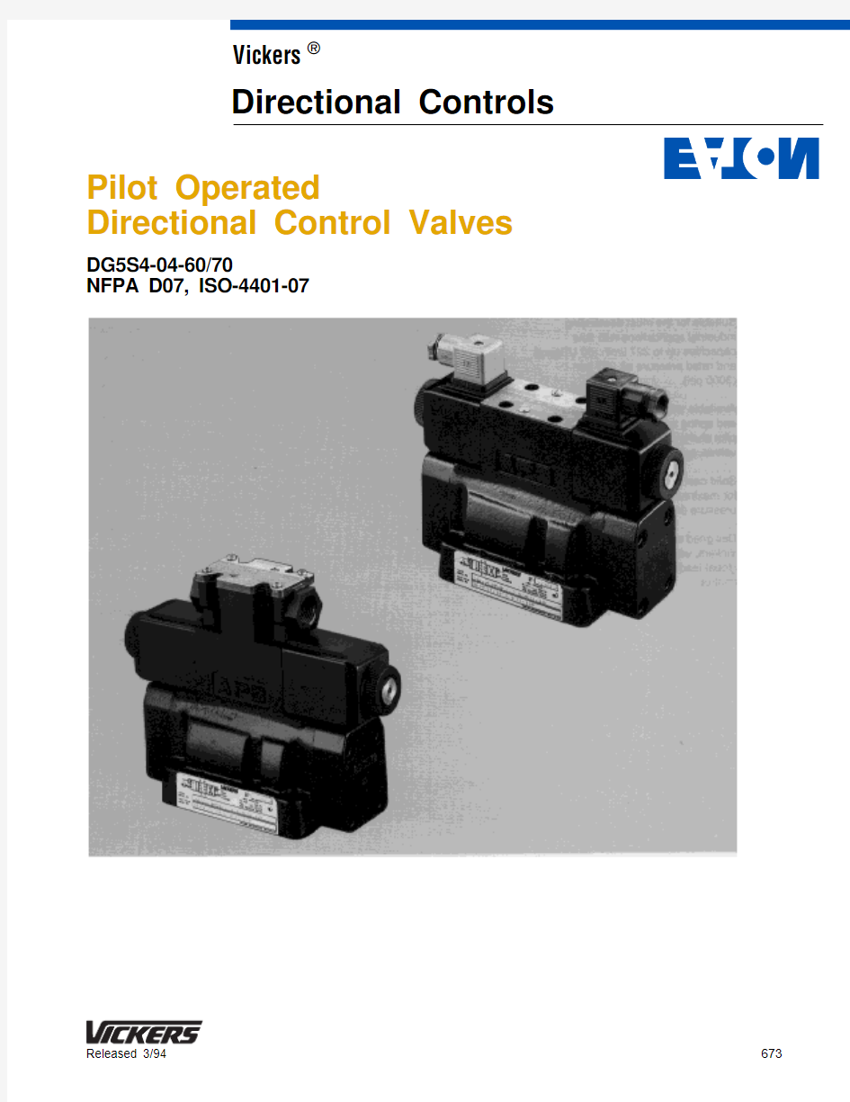
Pilot Operated
Directional Control Valves
DG5S4-04-60/70
NFPA D07, ISO-4401-07
673
Released 3/94Vickers ?
Directional Controls
Table of Contents
. . . . . . . . . . . . . . . . . . . . . . . . . . . . . . . . . . . . . . . . . . . . . . . . . . . . . . . . . . . . . . . . . . . . . . . . . . . . . . . . . DG5S4-04 Model Code4
. . . . . . . . . . . . . . . . . . . . . . . . . . . . . . . . . . . . . . . . . . . . . . . . . . . . . . . . . . . . . . . . . . . . . . . . . . . . . . . . . . . . General Information6 Basic Characteristics
Shifting Action
Mounting Position
Application
Installation Data
. . . . . . . . . . . . . . . . . . . . . . . . . . . . . . . . . . . . . . . . . . . . . . . . . . . . . . . . . . . . . . . . . . . . . . . . . . . . . . . . . . . . . . Optional Features7 Functional Symbols
Service Information
. . . . . . . . . . . . . . . . . . . . . . . . . . . . . . . . . . . . . . . . . . . . . . . . . . . . . . . . . . . . . . . . . . . . . . . . . . . . . Models & Graphical Symbols8
. . . . . . . . . . . . . . . . . . . . . . . . . . . . . . . . . . . . . . . . . . . . . . . . . . . . . . . . . . . . . . . . . . . . . . . . . . . . . . . . . . . . . . . . Pressure Drop9
. . . . . . . . . . . . . . . . . . . . . . . . . . . . . . . . . . . . . . . . . . . . . . . . . . . . . . . . . . . . . . . . . . . . . . . . . . . . . . . . . . . . . . . . . Flow Ratings10 . . . . . . . . . . . . . . . . . . . . . . . . . . . . . . . . . . . . . . . . . . . . . . . . . . . . . . . . . . . . . . . . . . . . . . . . . . . . . . . . . Installation Dimension11
. . . . . . . . . . . . . . . . . . . . . . . . . . . . . . . . . . . . . . . . . . . . . . . . . . . . . . . . . . . . . . . . . . . . . . . . . . . . . . . . . . Subplates & Bolt Kits13 . . . . . . . . . . . . . . . . . . . . . . . . . . . . . . . . . . . . . . . . . . . . . . . . . . . . . . . . . . . . . . . . . . . . . . . . . . . . . . . . . . Electrical Information14
. . . . . . . . . . . . . . . . . . . . . . . . . . . . . . . . . . . . . . . . . . . . . . . . . . . . . . . . . . . . . . . . . . . . . . . . . . . . . . . . . . . . . . Application Data18
Introduction
DG5S4-04 models are two-stage directional valves having an integrally mounted DG4V-3(S)-60 pilot valve. These valves are generally used to control the direction of flow in a hydraulic circuit. This in turn would control the movement of a work cylinder or the rotation of a fluid motor.
Features and Benefits
D Suitable for the most demanding industrial applications with flow capacities up to 227 l/min (60 USgpm) and rated pressure of 210 bar (3000 psi).
D Available with a wide variety of spool and spring arrangements, stroke and pilot choke adjustments, integral check valves, and port orifices.
D Solid cast body with cored passages for maximum strength and minimal pressure drop.
D Designed and manufactured by Vickers, with over 70 years as the global leader in fluid power and motion control.
Model Code
Pilot Operated Directional Valves
C -Spring centered
F -Shift to center from offset (single solenoid)
N -No-spring detented (pilot only)
Left-Hand assembly
L -Single solenoid models only. Omit for right-hand assembly. (For right-hand assembly P to A when solenoid ‘a’ is energized.)
Manual override options
Blank - Plain override solenoid end only H -Waterproof override solenoid
ends only
H2 -Waterproof override both ends of
single solenoid
P2 -Plain override both ends of single
solenoid.
Y -Lockable manual overrides
solenoid ends only/DC only Z -No overrides in either end
6
7
Blank - External pilot drain
Pressure port check valve
K -0,35 bar (5 psi) cracking pressure R -3,4 bar (50 psi) cracking pressure S -5,2 bar (75 psi) cracking pressure Blank - Omit if not required
Solenoid energization identity
V -Solenoid identification determined by position of solenoid (solenoid “A” at port “A” end and/or solenoid “B” at port “B”end)
Blank -Standard arrangement for ANSI B93.9 (energize solenoid “A” for flow P to A port)
(Code V for any valve with code 4 or code 8 spool)
(Code F coil only)
T -Wired terminal block
PA -Insta-plug male receptacle only PB -
Insta-plug male & female receptacle
PA3 - NFPA 3-pin connector PA5 - NFPA 5-pin connector Blank - Omit if not required
Housing
(Code F coil only)
W -1/2 NPT thread wiring housing J -20 mm thread wiring housing Blank - Omit if not required
Solenoid indicator lights
(Code F coil w/Code T electrical connections only)
L -Indicator lights
Blank - Omit if not required
12
13
18
19
Model Code cont’d
Coil identification
A -110V/50 Hz
B -110V/50 Hz, 120V/60 Hz
C -220V/50 Hz
D -230V/50 Hz, 240V/60 Hz
G -12V DC
H - 24V DC
DJ -98V DC
P -110V DC
Pilot valve tank pressure rating 2 -10 bar (145 psi) DG4V3-60 with S3,
S4, or S5 spool indicator switch
4 -70 bar (1000 psi) hazardous model
5 -100 bar (1450 psi) DG4V3S-60
6 -160 bar (2285 psi) DG4V3-60 with
AC solenoids and optional S6 spool indicator switch
6 -210 bar (3000 psi) DG4V3-60 with
DC solenoids and optional S6 spool indicator switch 2223
20Pilot valve port orifices
Code Orifice Diameter
*00 -Solid plug
*03 -0,30 mm (0.012 in)
*06 -0,60 mm (0.024 in)
*08 -0,80 mm (0.030 in)
*10 -1,00 mm (0.040 in)
*13 -1,30 mm (0.050 in)
*15 -1,50 mm (0.060 in)
*20 -2,00 mm (0.080 in)
*23 -2,30 mm (0.090 in)
Blank - Omit if not required
(* = P, T, A, and/or B as required)
Design number
Subject to change. Installation dimensions remain as shown for designs 60 through 69 and 70 through 79.
60 -DG4V3S-60 pilot valve
70 -DG4V3-60 pilot valve
Refer to GBC–2010 for more information on the pilot control valve.
21
General Information
Basic Characteristics
Max. pressure:210 bar (3000 psi) Max. flow:227 l/min (60 USgpm)
. . . . .
Max. pressure port T (external drain):
210 bar (3000 psi)
. . . . . . . . . . . . . . .
Max. pressure port T (internal drain): DG4V-3S100 bar (1450 psi)
. . . . . .
DG4V-3210 bar (3000 psi)
. . . . . . .
Max. pilot pressure:
210 bar (3000 psi)
. . . . . . . . . . . . . . .
Weights - See installation drawings. Mounting Interface
ISO-4401-07
NFPA D07
Shifting Action
Spring centered, pressure centered and spring offset models must be energized continuously to maintain the shifted position. Detented no-spring models may be energized momentarily (approximately 0.1 second).
Pressure centered and spring centered models return valve spool to center position when solenoids are
de-energized.
Spring offset models return spool to offset position by pilot pressure when solenoid is de-energized.
When no-spring detented models are de-energized, the pilot and main spools remain in the last position attained, provided there is no shock, vibration, unusual pressure transients and the spool axis is horizontal. If pilot pressure fails or falls below the minimum, the main spool will spring center (at spring centered flow rates) and cannot drift to reverse flow (pilot stage remains in detented position).
CAUTION
Surges of oil in a common tank line
serving these and other valves can
be of sufficient magnitude to cause
inadvertent shifting of these valves.
This is particularly critical in the
no-spring detented type valves.
Separate tank lines or a vented
manifold with a continuous
downward path to tank is necessary.
(This also applies to connection X on
spring offset valves, if X is piped as
a drain.)
NOTE
Any sliding spool valve, if held for
long periods of time, may stick and
not spring return due to fluid residue
formation and therefore, should be
cycled periodically to prevent this
from happening.
When used as other than a normal
4-way valve, consult your Vickers
representative.
Mounting Position
No-spring detented valves must be
installed with the longitudinal axis
horizontal for good machine reliability.
The mounting position of spring offset
models is unrestricted provided that the
pilot pressure supply is maintained as
required. (Spring offset valves do not
have a spring in the main spool section.)
Application
All spools at zero flow require 5,2 bar
(75 psi) minimum pilot pressure. At
maximum flow without malfunction 5,5
bar (80 psi) is required for open center
spools (types 0, 4, 8 & 9) and 8,6 bar
(125 psi) is required for closed center
spools (types 2, 3, 6, 31 & 33).
NOTE
The pilot pressure stated is based
on internally piloted and externally
drained models in which the pilot
pressure is equal to the pressure at
the valve pressure port. With models
having pressure open or partially
open to tank at center position, pilot
pressure can be assured by
imposing a back pressure of at least
the required minimum pilot pressure
at the tank outlet connection (this
back pressure will be present at
cylinder ports if spool is “0” or “9”
type). When pilot pressure from
separate source (external) is
required, an external connection can
be provided. Order according to
model code.
Installation Data
Pilot Valve Drain
Internal: To provide maximum flow
without malfunction, pilot pressure of
internally drained valves must always
exceed tank line back pressure by a
minimum of 5,2 bar (75 psi) for spool
types 0, 4, 8 & 9 and a minimum of 10,3
bar (150 psi) for all other spools.
Internal drain may be used with all
valves, however, an integral pressure
port check valve (ref. integral check
valve on page 5) is required for valves
using an internal pilot source with an
open center spool (0, 4, 8 and 9 types)
in order to maintain pilot pressure. If an
external pilot source is used, an integral
check is not required. When internal
pilot drain is required, order according to
model code. (Pressure centered valves
not included.)
External: When the possibility of
pressure surges in the tank line exists,
externally drained valves are
recommended. For externally drained
models, the pilot valve drain line must
be piped directly to tank through a surge
free line so there will be no back
pressure at this drain. (Reference
connection “Y”.)
Optional Features/Functional Symbols
Pressure Centered Drain (external only)
The external pilot drain explanation on the previous page applies to “Y ” drain port. Pressure centered “W ” drain connection must be piped directly to tank through a surge free line so there will be no back pressure at this drain.
Optional Features
Integral Check Valve
For open center spools - When using internal pilot pressure and internal pilot drain, select appropriate check spring model (K, R or S) from “Pressure Drop Across Check Valve ” curve on page 8.Total pressure drop required is 5,2 bar (75 psi), (see pilot pressure ratings and note) therefore, determine valve ?P (P to T) at the actual application flow rate.Subtract this value from 5,2 bar (75 psi)and call its value “C ”. Refer to the check valve pressure drop curve at the application flow rate and select the spring model letter whose curve is
above this pressure (bar/psi) value “C ”.
Fast Response
Use of this option decreases shift time approximately 60%. However, system shock generation is correspondingly increased. The fast response option is not recommended for pilot pressure exceeding 138 bar (2000 psi).
Service Information
Refer to specific Vickers parts drawing for service parts information. A complete parts breakdown is contained in this drawing.
Order by literature number.
DG5S4-04-60/70I-3891-S
. . . . . . . . . . . Typical shift times in milliseconds for spring centered valves at rated flow and pressure.(See note on fast response option.)
* Minimum pilot pressure
Functional Symbols
Double Solenoid - Spring centered “C ”
A B
Double Solenoid -
No-spring, detented “N ”
A B
Single Solenoid - Spring centered “B ”
Models & Graphical Symbols
Restricted flow
G 4 & 8 type spools - flow paths reversed.
Y Maximum flow limited to 170 l/min (45 USgpm) @ 69 bar (1000 psi), 76 l/min (20 USgpm) or 45 l/min (12 USgpm) @ 210 bar (3000 psi).
Pressure Drop
1. Figures in the pressure drop table
give approximate pressure drop (?P) when passing 95 l/min (25USgpm) flow (Q) of 21 cSt (100SUS) fluid(s) having .865 specific gravity.2.For any other flow rate (Q 1), the
pressure drop (?P 1) will be
approximately: ?P 1 = ?P(Q 1/Q)2119126132137141
Viscosity
cSt
(SUS)14(75)32(150)43(200)54(250)65(300)76(350)86(400)% of D P (Approx.)
931113.For any other viscosity(s), the
pressure drop (?P), will change as follows:
* Specific gravity of fluid may be obtained from its producer. The value is higher for fire-resistant fluids than for oil.
Note
When solenoid “a ” is energized, flow is always P to A. When solenoid “b ” is energized, flow is always P to B. This is in accordance with the ANSI-B93.9 standard. Standard spring offset valves are assembled right hand, such that flow is P to A in the spring offset position (solenoid is de-energized). Solenoid “a ” and “b ” are identified on the diagram plate.
4.For any other specific gravity (G 1)*,
the pressure drop (?P 1) will be approximately: ?P 1 = ?P(G 1/G)
Flow Ratings
Pressure Drop Across Check Valve
Total pressure drop is determined from the pressure drop induced by check valve and other sources. (See graph,pilot pressure and integral valve notes.)Total must be greater than minimum bar/psi for good machine reliability.To determine check valve cracking pressure needed to provide pilot
pressure, calculate total pressure drop through valve (P to T) on center at minimum flow. Total pressure drop is determined from pressure drop chart for standard valve and adding pressure drop induced by check valve (see graph). Total must be greater than the minimum for good machine reliability.(See pilot pressure and integral check valve notes.)
Flow Ratings
* As system flow increases the minimum pilot pressure required increases. These spools will operate satisfactorily in excess of 227 l/min (60 USgpm) with higher pilot pressures.
G Maximum flow limited to 170 l/min (45 USgpm) @ 69 bar (1000 psi), 76 l/min (20 USgpm) or 45 l/min (12 USgpm) @ 210 bar (3000 psi).{ Fast valve switching of large oil volumes, without adequate decompression circuitry, can develop instantaneous flows well above the maximum ratings. The type 8 spool may spin within the body, causing unusual valve body bore wear when applied in this type of circuit. With this and other spool types, valve malfunction might occur.
Flow - USgpm Flow - l/min
P r e s s u r e D r o p - b a r
P r e s s u r e D r o p - p s i 25
19385
10155075100120150175200
2025
30
577695114
2252501,7
3,45,26,98,310,312,113,815,517,2
73,2(2.88)69,9(2.75)
51,6(2.03)
Y B A
X
P
T
Double Solenoid, Spring Centered &
No-Spring Detented Types
Millimeter (inches)
Weight @ 6,8 kg (15 lbs)
For 7,1 (.281) dia.hole
35,1(1.38)
For 7,1 (.281) dia.holes 67,6(2.66)
101,6(4.00)
?10,3 (.406)
4 holes for mounting Pilot valve drain port.
External pilot drain models (connect to reservoir).
Port A
Pilot pressure port (for ext. pilot
pressure models)
Port B
Pressure Port
Tank Port
163,8(6.45)220,0(8.66)
DC Models 200,0(7.87)AC Models
93,00(3.66)73,2(2.88)
173(6.81)
61 (2.5) DC
51 (2.1) AC for coil removal
120(4.75)
70(2.75)
35,8(1.41)
33,3(1.31)
27(1.06)
25,4(1.00)
142(5.59)
89(3.50)
44,5(1.75)3,0 (.12)
?6,4 (.25)50,8(2.00)
Electrical conduit connection 1/2
NPTF thread (both ends)Port A test conn.1/8 NPTF thread Port B test
conn. 1/8 NPTF thread
?7,1 (.281) ? 2 holes for mounting
36,6(1.44)
Single Solenoid -Spring Offset, Spring Centered & Shift-to-Center
Millimeter (inches)
Weight @ 6,4 kg (14 lbs)
DC Models
156(6.14)AC Models
146(5.75)Right-hand assembly shown
Standard solenoid
position for right-hand models (except when 4 & 8 spool is used in B models)
Standard solenoid position for left-hand models (except when 4 & 8 spool is used in B models)
Pilot Choke and Stroke Adjustments
Pilot Choke Adjustment(s)
Pilot choke is adjusted by backing off locknuts and turning adjusting screws inward (clockwise) to decrease rate of spool travel and outward
(counterclockwise) to increase the rate.Pilot oil for models with this feature
should be taken from a source having a constant pressure. See spool control modifications in model code.
Stroke Adjustment(s)
Stroke adjustment limits movement of the main stage spool. Backing off the jam nut and turning the adjusting screw
inward (clockwise) decreases spool stroke. See spool control modifications in model code.
Weights:Dual pilot - 8,6 kg (19 lbs)
1 Stroke adj. - 6,9 kg (15.3 lbs)
2 Stroke adj. - 7 kg (15.5 lbs)Pilot choke & Stroke adj. -8,8 kg (19.5 lbs)
160(6.29)
79(3.10)
88,9
(3.50)254(10.0)
Pilot choke adjustment
Stroke
adjustment
26,9(1.06)
Subplates & Bolt Kits
Valves, subplates and mounting bolts must be ordered separately.
Example:
One (1) DG5S4-040A-M-W-*-** Valve One (1) DGSM-04-12S-20 Subplate One (1) BKDG-04-650 Bolt Kit {
{ Maximum recommended bolt torque 1/4
” screws - length 1.50” - 12,7 Nm (112 in. lbs.)
3/8
” screws - length 1.75” - 35,6 Nm (315 in. lbs.)
Weight: @ 3,2 kg (7 lbs)
When subplate is not used, a machined pad (as indicated by subplate shaded area, below) must be provided for mounting. Pad must be flat within 0,0127 mm (.0005 inch) and smooth within 1,6 μm (63 microinch). Mounting bolts, when provided by customer,should be SAE grade 7 or better.
Pilot Valve Port Restrictor Plugs
Restrictor plugs are available for use in ports P , T, A, or B. These can be used for restricting flow or for circuit
dampening. Restrictor plugs are not recommended for use above 210 bar (3000 psi) system pressure.Part
Number {Orifice ?Model Code 694353Blank *006943410,30 (0.012)*036943420,60 (0.024)*066943430,80 (0.030)*08694344
1,00 (0.040)
*10
6943451,30 (0.050)*136943461,50 (0.060)*156943472,00 (0.080)*20694348
2,30 (0.090)
*23
{ –Available in multiples of 25 per part
number
* – P , T, A, or B as required
Solenoids
On all models when solenoid A is energized, flow is always P to A. When solenoid B is energized, flow is always P to B. This is in accordance with the ANSI-B93.9 standard. Solenoid A and B are identified on the main plate on the top of the valves terminal box. Single solenoid models can be assembled
left-hand (flow is P to B when solenoid A is energized).Solenoid Energizing
Spring centered and spring offset types
will be spring positioned unless solenoid
is energized continuously. No-spring
detented valves may be energized
momentarily, approximately 0.1 second;
when solenoid is de-energized spool will
remain in last position attained provided
there is no shock, vibration, or unusual
pressure transients.
Electrical Connection
A 1/2” NPTF thread connection is
provided on both ends of the terminal
box. This connection will readily accept
common electrical quick disconnect
assemblies on the market. The wiring
housing is available with most options.
Solenoid Indicator Lights
Light is “on” when there is current at the
solenoid coil. Lights are available for
various voltages in both AC and DC
service.
Feature Standard Performance Valve DG4V-3S-*-60
Pilot Valve Operating Data
High Performance Valve
DG4V-3-*-60
Electrical Protection
ISO 4400 coils w/plug Conduit box
Vickers Insta-Plug
Coil Winding
Lead wires (coil type F) Coil encapsulation IEC 144 class IP65
IEC 144 class IP65
IEC 144 class IP50
Class H
Class H
Class F
IEC 144 class IP65
IEC 144 class IP65
IEC 144 class IP50
Class H
Class H
Class F
Typical response times at 100% rated volts measured from application/removal of voltage to full spool displacement of 2C spool at:
Flow rate P to A, B to T Pressure
AC energizing
AC de-energizing
DC energizing
DC de-energizing 20 l/min (5.3 USgpm)
175 bar (2538 psi)
18 ms
32 ms
60 ms
40 ms
40 l/min (10.6 USgpm)
175 bar (2538 psi)
15 ms
23 ms
45 ms
28 ms
Power consumption, AC solenoids Initial z
VA (RMS)
Holding
VA (RMS)
Initial z
VA (RMS)
Holding
VA (RMS)
Full power coils:
Single frequency coils AC 50 Hz Dual frequency coils at 50 Hz Dual frequency coils at 60 Hz Low power coils, “B” & “D”:
Dual frequency coils at 50 Hz Dual frequency coils at 60 Hz 22539
26549
26048
22554
28061
30058
Low power coils not usable with
DG4V-3S valves.
17037
19037
Power consumption, DC solenoids Full power coils:
12V, model type “G”
24V, model type “H”
Low power coils, “B” & “D”: 12V, model code “G”
24V, model code “H”30W–
30W–
30W–
30W–
Low power coils not usable with
DG4V-3S valves.
18W–
18W–
z First half cycle; armature fully retracted.
DIN Standard 43650 Plug-in Connectors
Connector can be positioned at 90_intervals on valve by re?assembling contact holder into appropriate position inside connector housing.Connectors with and without indicator (AC or DC)
A" sol. B" sol.
12-24100-125200-240
977467977469977471977466977468977470
710775
710776Without
lights With lights
Receptacle
Plug connector (Order separately) (ISO4400/DIN 43650)Cable diameter range:?6–10 mm (0.24–0.40)
Wire section range:?,5–1,5 mm 2 (0.0008–0.0023 in 2)Terminals:
Screw type
Type of protection:
IEC144 class IP65, when plugs are fitted correctly to the valves with the interface seals (supplied with plugs) in place.
Insta-Plug Option
Vickers “Insta-Plug” provides a means of disconnecting electrical power to the valve without actually breaking individual wire connections. The male half of the plug is attached to the top of the valve body. Solenoid leads are connected to this half of the plug by Vickers. The mating plug is attached inside the wire housing. Terminals are provided on top of it for the convenience of connecting machine wires.
Two thumb screws are used to hold the wiring housing with the female plug half to the valve. These screws are captive to avoid loss when servicing. To disconnect the valve they are loosened until clear, allowing the wiring housing to be pulled away from the valve body; thereby disconnecting electrical power to the valve. Note that the ground fifth post is longer than the other four, providing a first-make/last-break ground feature.The PB configuration includes both the male and female (retained in the housing) halves for a complete plug-in unit.
Solenoid indicator lights can also be furnished with the Insta-Plug feature. When furnished, the lights are pre-wired to the female half of the plug. Solenoids A and/or B are identified on the identification plate attached to the wiring housing.
Clearance to
NFPA Hydraulic Valve Electrical Connector
The receptacle is a standard three or five pole electrical connector with shortened leads and terminals added. The five pole plug has four leads 101,6 mm (4.0”) long and one 177,8 mm (7.0”) long. The three pole plug has two leads 101,6 mm (4.0”) long and one 177,8 mm (7.0”) long.All of the wires have Underwriters recognized non-solder insulated eyelet terminals. The #4 and #2 leads are attached to the “A” solenoid, and the #5 and #1 leads are attached to the “B”solenoid. The green wire is used for the ground connection (#8 screw furnished).
Electrical Connector Plug Millimeters (inches)
on single solenoid models, and over “b”solenoid on dual solenoid models. See diagram plate for “b” solenoid location.Electrical rating 600 volts, 3 pole, 10 amps and 5 pole, 8 amps. The female portable plug to be furnished by customer.
Application Data
Fluid Cleanliness
Proper fluid condition is essential for long and satisfactory life of hydraulic components and systems. Hydraulic fluid must have the correct balance of cleanliness, materials, and additives for protection against wear of components, elevated viscosity, and inclusion of air. Essential information on the correct methods for treating hydraulic fluid is included in Vickers publication 561“Vickers Guide to Systemic Contamination Control” available from your local Vickers distributor or by contacting Vickers, Incorporated.
Recommendations on filtration and the
selection of products to control fluid
condition are included in 561.
Recommended cleanliness levels, using
petroleum oil under common conditions,
are based on the highest fluid pressure
levels in the system and are coded in
the chart below. Fluids other than
petroleum, severe service cycles, or
temperature extremes are cause for
adjustment of these cleanliness codes.
See Vickers publication 561 for exact
details.
Vickers products, as any components,
will operate with apparent satisfaction in
fluids with higher cleanliness codes than
those described. Other manufacturers
will often recommend levels above
those specified. Experience has shown,
however, that life of any hydraulic
component is shortened in fluids with
higher cleanliness codes than those
listed below. These codes have been
proven to provide a long, trouble-free
service life for the products shown,
regardless of the manufacturer.
System Pressure Level
bar (psi)
Product<70 ( <1000)70-210 (1000-3000)210+ ( 3000+) Vane Pumps – FIxed20/18/1519/17/1418/16/13 Vane Pumps – Variable18/16/1417/15/13
Piston Pumps – Fixed19/17/1518/16/1417/15/13 Piston Pumps – Variable18/16/1417/15/1316/14/12
Proportional Valves17/15/1217/15/1215/13/11 Cylinders20/18/1520/18/1520/18/15 Vane Motors20/18/1519/17/1418/16/13 Axial Piston Motors19/17/1418/16/1317/15/12 Radial Piston Motors20/18/1419/17/1318/16/13
Fluids and Seals
Flourocarbon seals are available and
are suitable for use with phosphate
ester type fluids or their blends, water
glycol, water-in-oil emulsion fluids and
petroleum oil. Refer to 694 for hydraulic
fluid and temperature recommendations.