
V
RSM
V (BR)min ?x V RRM Anode Cathode V V V on stud on stud 900-800DS 75-08B DSI 75-08B 1300-1200DS 75-12B DSI 75-12B 130013001200DSA 75-12B DSAI 75-12B 170017601600DSA 75-16B DSAI 75-16B 1900
1950
1800
DSA 75-18B
DSAI 75-18B
x Only for Avalanche Diodes
Symbol Test Conditions Maximum Ratings
I F(RMS)T VJ = T
VJM
160A I F(AV)M T case = 100°C; 180° sine
110A P RSM DSA(I) types, T VJ = T VJM
, t p = 10 m s 20
kW I FSM
T VJ = 45°C;t = 10 ms (50 Hz), sine 1400A V R = 0t = 8.3 ms (60 Hz), sine 1500A T VJ = T VJM t = 10 ms (50 Hz), sine 1250A V R = 0
t = 8.3 ms (60 Hz), sine 1310A I 2t
T VJ = 45°C t = 10 ms (50 Hz), sine 9800A 2s V R = 0t = 8.3 ms (60 Hz), sine 9450A 2s T VJ = T VJM t = 10 ms (50 Hz), sine 7820A 2s V R = 0
t = 8.3 ms (60 Hz), sine
7210A 2s T VJ -40...+180
°C T VJM 180°C T stg -40...+180
°C M d Mounting torque
2.4-4.5Nm 21-40lb.in.Weight
21
g
V RRM = 800-1800 V I F(RMS)= 160 A I F(AV)M = 110 A
Features
q International standard package,JEDEC DO-203 AB (DO-5)q
Planar glassivated chips
Applications
q High power rectifiers
q Field supply for DC motors q
Power supplies
Advantages
q Space and weight savings q Simple mounting
q
Improved temperature and power cycling
q
Reduced protection circuits
Symbol Test Conditions Characteristic Values
I R T VJ = T VJM ; V R = V RRM £6mA V F I F
= 150 A; T VJ = 25°C £
1.17V V T0For power-loss calculations only 0.75V r T T VJ = T VJM 2m W R thJC DC current 0.5K/W R thJH DC current
0.9K/W d S Creepage distance on surface 4.05mm d A Strike distance through air 3.9mm a
Max. allowable acceleration
100
m/s 2
Dimensions in mm (1 mm = 0.0394")
Data according to IEC 60747
IXYS reserves the right to change limits, test conditions and dimensions
744
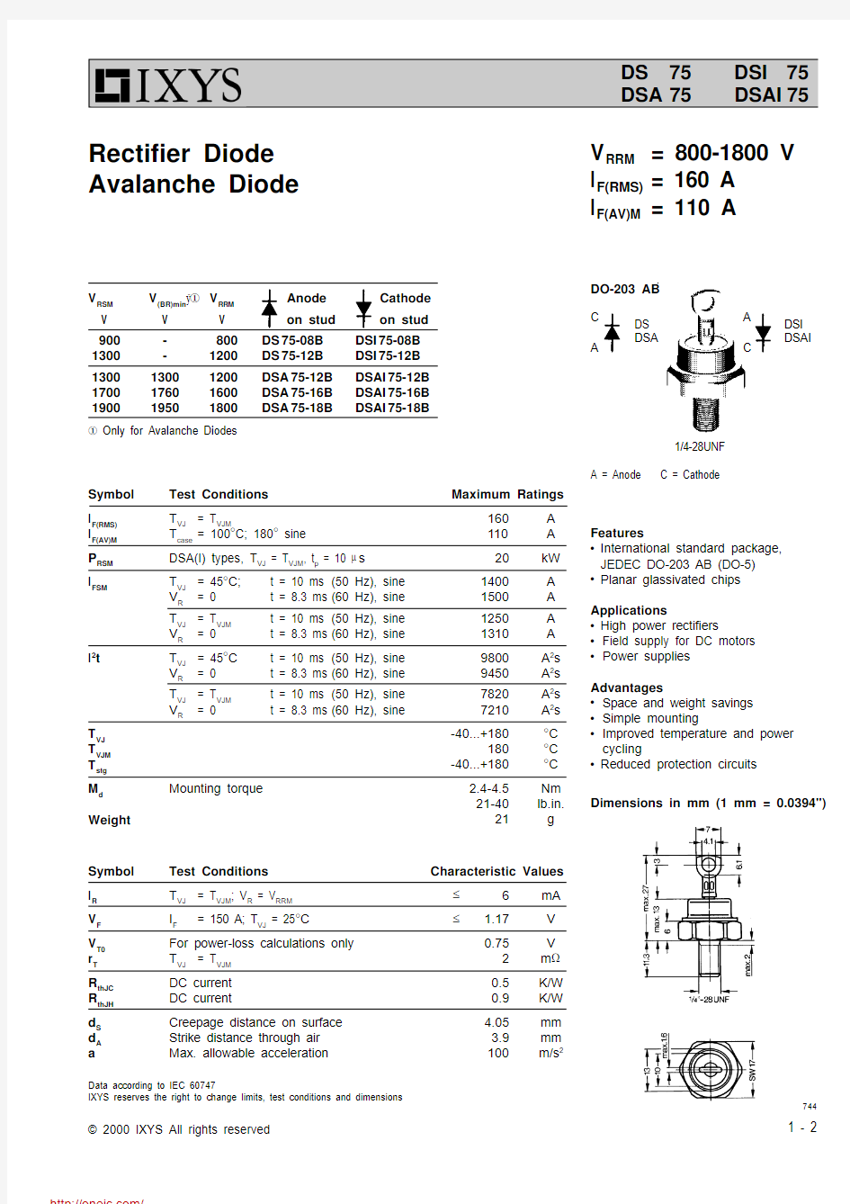
Rectifier Diode Avalanche Diode
A = Anode C = Cathode
DO-203 AB
1/4-28UNF
DS DSI DSA
DSAI
C A
A C
0.0
0.5
1.0050
100
150
2000501001502000.00.5
1.0
1.5I F A V P F
W
Z thJH
Fig. 1Forward characteristics
typ. lim.
T VJ = 180°C T VJ = 25°C
分销商库存信息:
IXYS
DSA75-16B DSA75-18B DSI75-12B DSA75-12B DSAI75-12B DSAI75-18B DSAI75-16B