
Advances in WINNER, COST2100 and METIS 5G Channel Model Simulation Research and Application
Yanbo YU
School of Electrical and Electronic Engineering,
North China Electric Power University, Beijing, 102206, China
Abstract—The WINNER channel model is a generic model, whose scenario-specific parameters are determined from extensive wideband MIMO radio-channel measurement campaigns and results found in the open literature. The COST 2100 channel model is a geometry-based stochastic channel model (GSCM) for multiple-input multiple output (MIMO) simulations.METIS is developing a 5G system concept that meets the requirements of the beyond-2020 connected information society and supports new usage scenarios. To meet the objectives METIS uses Horizontal Topics (HT) that addresses a key new challenge, identifies necessary new functionalities and proposes HT-specific concepts. Here, we will talk about some advances in WINNER, COST2100 and METIS 5G channel simulation model research and application in recent years. Index Terms—WINNER, COST 2100, 5G, Channel Model Simulation
I.INTRODUCTION
The WINNER wideband MIMO radio channel model has been developed in the course of the ISTWINNER project as a part of a system-level test platform. The model was developed in order to provide a reliable tool for estimation of system performance, covering frequencies in the range from 2-6 GHz and bandwidths up to 100 MHz in different types of propagation environments.
The COST 2100 channel model is a geometry-based stochastic channel model (GSCM) that can reproduce the stochastic properties of MIMO channels over time, frequency, and space. In contrast to other popular GSCMs, the COST 2100 approach is generic and flexible, making it suitable to model multi-user or distributed MIMO scenarios. In this article a concise overview of the COST 2100 channel model is presented. Main concepts are described, together with useful implementation guidelines. Recent developments, including dense multipath components, polarization, and multi-link aspects, are also discussed.
The fifth generation (5G) of wireless networks aims, among others, at fulfilling the goals which have been set by regulatory authorities regarding the seamless connectivity of all types of devices. In various studies, it is evident that next generation networks should allow smart objects ranging from sensors and actuators to user equipments (UEs) and vehicles, to connect and communicate in the Internet of Things (IoT). Through the IoT, novel applications such as smart cities, smart energy grids, vehicle-to-vehicle communications and health-oriented body area networks are expected to become a reality.
II.THE WINNER CHANNEL MODEL
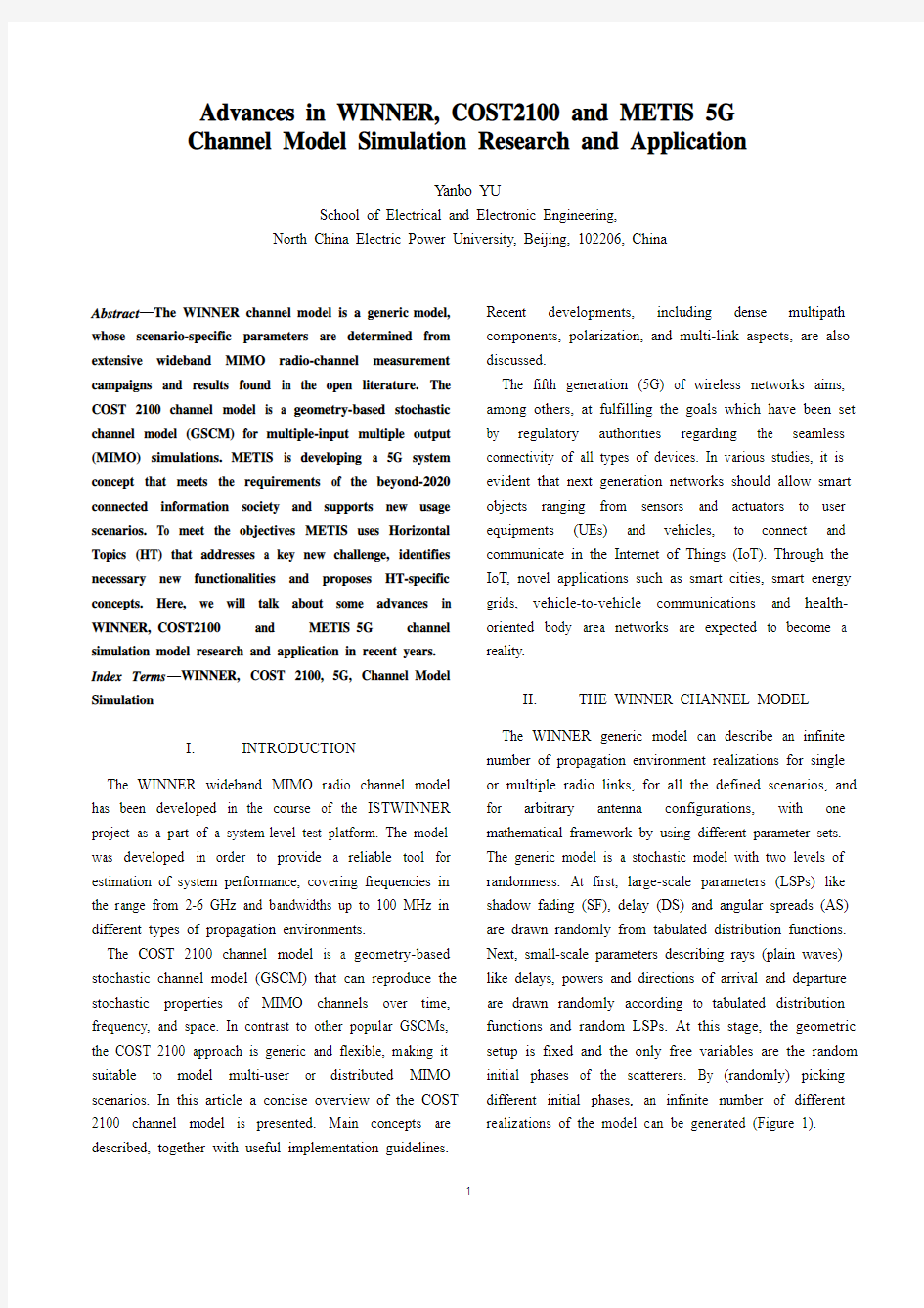
The WINNER generic model can describe an infinite number of propagation environment realizations for single or multiple radio links, for all the defined scenarios, and for arbitrary antenna configurations, with one mathematical framework by using different parameter sets. The generic model is a stochastic model with two levels of randomness. At first, large-scale parameters (LSPs) like shadow fading (SF), delay (DS) and angular spreads (AS) are drawn randomly from tabulated distribution functions. Next, small-scale parameters describing rays (plain waves) like delays, powers and directions of arrival and departure are drawn randomly according to tabulated distribution functions and random LSPs. At this stage, the geometric setup is fixed and the only free variables are the random initial phases of the scatterers. By (randomly) picking different initial phases, an infinite number of different realizations of the model can be generated (Figure 1).
Figure 1: The single realization of the modelled MIMO Channel.
Channel realizations between transmitter antenna elements and receiver antenna element u are generated by summing contributions of N clusters, each having M rays:
(1)
The superposition (1) of specular paths, with different propagation delays τn,m results in the correlation between antenna elements and temporal fading with a geometry dependent Doppler spectrum.
The complex, polarimetric response of an element in the antenna array:
(2)
describes deterministic influence of antenna to a propagation channel. A directional filtering of an antenna is defined for two orthogonal polarizations by field patterns
(),F θθ?and (),F ?θ?. The spatial
displacement of an antenna element inside array, described by vector d x x y y z z i d i d i d ++= will cause phase
shift
(),d
j K e
θ?that is dependent on angle of
departure/arrival, since
(3)
The current WIM2 implementation considers only 2D propagation of rays (zero-elevation plane), however the model will be extended to support full 3D propagation. The
suitable Polari metric representation for 3D antenna arrays is already defined and distributions of elevation angles are provided for indoor scenarios.
An influence of the environment to the orthogonal wave polarizations
is
described
by cross-polarization
discrimination ratios (XPRs) and represented in 22? matrix ,n m α . Term
,2n m j t
e
πυ in (1) describes changes of
ray phases that are consequence of terminal movement, and it is used to simulate small-fading effects A. Environment characterization – scenarios
The WINNER reference propagation scenarios are defined based on system-deployment schemes of Wide Area (WA), Metropolitan Area (MA), and Local Area (LA) concept groups. The required number of scenarios is kept low, due to the limited time resources for system performance simulations. Therefore, each deployment scheme (WA, MA, LA) was described by as few propagation scenarios as possible.
The WINNER measurement campaigns are conduced in radio environments providing the best match to defined reference scenarios. In the phase I of WINNER project, channel model WIM1 was parameterized for 7 different radio environments (scenarios): Al-Indoor (small office/residential), B1-Typical urban micro-cell, B3-Indoor hotspot, B5-Stationary feeder links, Cl- Suburban, C2-Typical urban macro-cell and Dl-Rural macro-cell. In WIM2, five new scenarios were modelled: A2-Indoor-to-outdoor, B4-Outdoor-to-indoor,D2-Moving networks, and Bad Urban extensions for microcell (B2) and macro-cell (C3) scenarios.
A typical example of moving network scenario (Figure 2) occurs in carriages of high-speed trains where wireless coverage is provided by so-called Moving-Relay-Station (MRS) having outdoor antenna on the top of the vehicle and indoor antenna that is mounted e.g. in the ceiling. In this scenario, radio-link consists of two parts: i) connection from a Base-Station (BS) to the MRS - D2a scenario, and ii) an indoor connection from the MRS to the Mobile-Station (MS)-D2b scenario.
()()()()T
,d
F ,,,,j K F F e θ?θ?θ?θ?θ???=???
()()()()()
()2K ,sin cos sin cos .
x y z i i i πθ?θ??θλ??=++??()()()(),2,,,,,11
,,,n m N
M
T
R T j t
u u s n m s n m n m n m n m h t F F e πντθ?αθ?δττ==????=?-????∑∑
.
Figure 2: Moving network reference scenario.
The link between BS and MRS is typically a LOS wireless link (the tunnels are neglected for the time being) whose propagation characteristics are similar to scenario Dl. The WIM2 D2a model is therefore based on existing Dl model, "bridge-to-car highway hot spot" measurements, and the fast-train measurements with SIMO setup.
In indoor environment, dominant wave contributions from MRS will be, in general, accompanied by much weaker components, with larger excess delay and moderate to extremely large Doppler shift, coming from stationary BS. However, since ICE trains have windows with metallized coating, indoor propagation environment (D2b) will be largely independent of the vehicle's velocity and similar to those found in stationary indoor environments, such as propagation scenario Al. Therefore, indoor MIMO measurements are performed inside stationary ICE train, and WIM2 D2b parameters are to be provided.
Indoor-to-outdoor scenario (Figure 3.a) corresponds to indoor BS serving outdoor MS, while in outdoor-to-indoor case (Figure 3.b) indoor MS are served by outdoor BS.
Figure 3: Indoor-to-outdoor and outdoor-to-indoor reference
scenarios.
These scenarios are quite similar (see Table 1), except for the fact that the outdoor BS can be higher than the outdoor MS, and can have greater EIRP allowance than indoor BS.
Table 1: Deployment assumptions for A2 and B4 scenarios.
B.Model features
1)Model evolution
Compared to earlier versions, WINNER models have kept the concept of channel segments (drops in SCM). The channel segment corresponds to a local stationarity interval, during which propagation delays and DoA/DoDs, as well as LSPs: DS, AS and SF, do not change considerably. The original SCM/WIM1 framework defines quasi-stationary environment in which consecutive simulated channel
segments do not necessarily follow predefined mobile route. Instead, they correspond to randomly chosen positions of MSs. Attempts to introduce continuous evolution of angles and delays in extended SCM [4] have resulted in the computationally complex model that is not suitable for system-level simulations. Since a time-evolution of the channel model may have a considerable impact to the system performance evaluation, the new low-complexity approach is adopted for WIM2. The route to be modelled is covered by adjacent channel segments (Figure4.a), where the distance between
segments,
s
d, is equal to the local stationarity interval. In
order to support "smooth" model evolution in time, transitions from segment to segment are carried out by replacing clusters of the "old" segment by clusters of the "new" segment, one by one, by linearly decreasing/increasing their powers. The substitution method is depicted in the Figure 4.b).
The route between adjacent channel segments is divided to number of sub-intervals equal to maximum number of clusters within the channel segments, max {NA, NB}. During each sub-interval the power of one old cluster ramps down and one new cluster ramps up. Clusters from the old and new segments are coupled based on their power. If number of clusters is different in the channel segments
the weakest clusters are ramped up or down without a pair from other cluster.
With this concept, transitions between LOS/NLOS propagation conditions and different scenarios are supported.
Figure 4: Model evolution: a) Channel segments over mobile route, b) Smooth transition between channel segments by power ramp-up and ramp-down of clusters.
2)Intra cluster delay spread
The clusters identified from measurements are, in general, dispersed in angular and delay domains. In order to simplify model and to establish straightforward relation to tapped-delay-line (TDL) model, SCM/WIMI have introduced clusters with "Zero-Delay-Spread" (ZDS). Since WINNER channel model is targeting much broader frequency bandwidths, the total number of identified ZDS clusters (and paths) in WIMI was larger then for SCM. Dispersion in delay domain was firstly introduced as WINNER extension of SCM to account for higher bandwidths and to reproduce the proper level of the frequency correlation.
In [17] it is showed that SCME with intra-cluster delay spread shows similar frequency correlation as WIMI based on ZDS clusters, however the total number of paths was considerably lower in the SCME case. As a compromise between complexity and performance, delay dispersion is also added to the two strongest clusters in WIM2: The original SCM/WIMI angular-only distributed paths of a single cluster are re-grouped to three fixed delay positions (Figure 5), thus the cluster subdivision in delay domain does not increase total number of paths.
The RF implementation of the WINNER II CDL channel model in the MIMO OTA test system is investigated. To reduce the cost and complexity of the test system, the channel model is simplified according to a systematic approach, and implemented through a comprehensive simulation study.
Figure 5: An introduction of the delay dispersion to the two strongest WIM2 clusters: the fixed delay offsets in respect to an excess delay of the original cluster are 0, 5 and 10 ns, and normalized powers of sub-clusters are 10/20, 6/20 and 4/20.
3)System-level correlations: intra- and inter- cell
The main distinction between system and link level simulations lay in the dependence (correlation) of parameters describing different links. At the system level two types of correlations could be identified (Figure 6): a) intra-cell correlations between MSs connected to the same BS, and b) inter-cell correlations of links from the single MS to multiple BSs.
Figure 6: Links toward common station exhibits correlations: a) intra-cell, and b) inter-cell.
In both types of correlation, environment similarity comes from common scatterers contributing to different links. However, due to different deployment assumptions for BS and MS (height, density), difference between intra- and inter-cell correlations are observed in measurement data.
III.THE COST 2100 CHANNEL MODEL
The COST 2100 MIMO channel model is a GSCM that was built on the framework of the earlier COST 259 and 273 models [3]. The COST 259 channel model [4] was the first GSCM considering multi-antenna base stations, while full MIMO systems were later targeted by the COST 273 model. The COST 2100 channel model extends the COST 273 model to cover MIMO systems at large, including multi-user, multicellular, and cooperative aspects, without requiring a fundamental shift in the original modeling philosophy. This article aims to give a concise overview of the COST 2100 channel model, covering the overall structure as well as the individual key elements constituting the model framework. The most recent achievements, including multi-link aspects, are presented, while considerations about parameterization, implementation, and validation are discussed later.
1)General structure of the cost 2100 channel model The COST 2100 channel model was originally proposed for simulating the radio channel between a static multiple-antenna BS and a multiple-antenna MS. In most cases, the MPCs are mapped to the corresponding scatterers, and are characterized by their delay, azimuth of departure (AoD), elevation of departure (EoD), azimuth of arrival (AoA), and elevation of arrival (EoA). Clusters are formed by grouping scatterers that generate MPCs with similar delays and directions (azimuth and elevation). Figure 7 depicts the scattering mechanisms from the BS to the MS. There are three kinds of clusters in the COST 2100 model, as illustrated in Figure 7. Local clusters are located around the MS or the BS, and those are characterized by single-bounce scatterers only. Far clusters are divided into single-bounce and multiple-bounce clusters. They are distributed throughout the simulation area, with an average density following a Poisson distribution. Given the geometrical cluster distribution, the LSPs of a channel are actually controlled by the average number of clusters that are active (i.e., visible to the MS) and thus contributing to the channel. While local clusters are always visible, the visibility of a far cluster is determined by the concept of visibility region, which confines the cluster activity within a limited geographical area. As mentioned, the far clusters include clusters with single-bounce scatterers and clusters with multiple-bounce scatterers. Single-bounce clusters can explicitly be mapped to a certain position by matching their delay and angles through a geometric approach. On the contrary,the multiple-bounce clusters are described by two representations, as viewed from the BS and MS sides, respectively, and called twin clusters. Visually, a twin cluster contains two identical images of one cluster, appearing at both sides (Fig. 7). In a specific environment, the ratio of twin to single-bounce clusters is set to be constant.
Eventually, the channel impulse response (CIR) is obtained by the superposition of the MPCs from all active clusters determined by the position of the MS. The amplitude of each MPC is jointly determined by the path loss, the large-scale properties of the cluster to which it belongs, and its own small-scale properties. The CIR can then be combined with antenna steering vectors to form the
MIMO channel matrix (discussed later).
Figure 7:General structure of the COST 2100 channel model 2)Key modeling concepts
Visibility regions. A visibility region (VR) is a circular region given fixed size in the simulation area. It determines the visibility of only one cluster.In the COST 2100 model, the VRs are uniformly distributed in the simulation area, the VR density being related to the average number of visible clusters determined experimentally.
Clusters.A cluster is depicted as an ellipsoid in space as viewed from the BS and from the MS,as illustrated in Fig.8. The local cluster and the far clusters are characterized with specific positions and orientations toward the BS and MS, respectively, so their spatial spreads match their corresponding delay and angular spreads. The geometric correspondence between the cluster spatial spread and the cluster delay and angular
spreads is simple. For instance, the length
C
a, width
C
b,
and height
C
h of the single-bounce cluster in Figure 8
correspond to the cluster delay, azimuth, and elevation spreads, respectively.
Figure 8: Spatial description of a) local; b) single-bounce; c) twin clusters: a c, b c, and h c represent the length, width, and height of the cluster; d C, MS and d C, BS are the distances from the cluster to the MS and BS, respectively.
Line of sight and multipath components.The LOS component is the direct propagation path from the BS to the MS. The COST 2100 model considers the LOS component as a special cluster containing only one MPC, whose power is randomly scaled with respect to the active cluster power. The visibility of the LOS component is also associated with a VR, which is characterized by its own size and distribution.
Time evolution.The COST 2100 framework enables a time-varying channel description using a single realization of the clusters as long as the environment remains static. Indeed, the environment (i.e., the clusters and the VRs) is generated independent of the MS position. This is actually very similar to the generation of virtual environments. While virtual environments reproduce the exact location and shape of scatterers (buildings, obstacles, etc.), clusters and their visibility regions stochastically represent a typical environment. As mentioned, a whole different approach is followed from WINNER II, where small (stationary) pieces of MS motion are connected by correlating the LSPs between these pieces, thereby enabling explicitly non-stationary channels to be simulated. In the COST family of models, the whole environment is first generated, and the movement of the MS in this simulation area causes the visibility of different clusters to change as the MS enters and leaves different VRs, resulting implicitly in non-stationary channel simulations. This also implies that the COST 2100 model structure and parameterization are independent of the MS speed: the higher the speed, the faster the MS moves in and out of visibility regions, decreasing the stationarity length of the channel. Thereby, scenarios involving high-speed MSs can readily be simulated using the COST 2100 approach.
3)COST 2100 novel developments
Polarization.The polarization behavior of the channel is described on the cluster level. As proposed by [7], an MPC contains four polarization components: vertical-to-vertical (VV) polarization, horizontal-to-horizontal (HH) polarization, vertical-to-horizontal (VH) polarization, and horizontal-to-vertical (HV). The polarization components can then be projected accordingly onto the MIMO antenna array to form multi-polarized sub-channels. The power ratios between the four polarization components of each MPC is characterized by a polarization matrix [7]. These ratios follow different lognormal distributions with a mean and standard deviation generated per MPC. Each polarization component also contains a uniformly distributed random phase.
Dense multipath components.There are two approaches to include diffuse scattering:
?By extending the propagation paths with a continuous dispersion over delay and angular domains to include diffuse scattering characteristics.
?By the superposition of a large number of specular paths with modified delays, angles, and amplitudes, called the dense multi-path components (DMCs) .
Whereas the first method relies on the quality of the path dispersion modeling, the model mismatch might create a significant amount of artifacts; the second method increases the total number of parameters but provides the best capture of the residual channel spectrum as long as the number of the DMCs is sufficiently large. The COST 2100 model considers the second approach as a direct extension of the MPC concept.
Multi-link aspects.Multi-link communications refer to concurrent communications between multiple BSs and multiple MSs that are spatially separated.This structure is usually interesting for cooperative schemes and multi-user signal processing to exploit the spatial variety of different radio links. The single-link COST 2100 model supports multi-user scenarios by definition, as it characterizes the propagation environment with respect to one
BS
(
)()()()()()
,,,,1
1,P l M n p t n p r n p n n p n p H t V a s s L ξτδτττ∈=?=
Ω?ψ--??
∑∑irrespective of the MS location, so channels between one BS and multiple MSs at different locations can be characterized simultaneously. A similar principle could be further applied to model channels in multiple-BS multiple-MS scenarios, simply by adding up multiple single-link channel realizations. However, since clusters and the corresponding visibility regions have been conventionally generated separately and independently for each BS, there is no guarantee that the multiple links reflect the important features of the multilink scenarios realistically, particularly large scale correlations.
4) Parameterization, implementation, and validation Parameterization. The parameterization of the COST 2100 model in various scenarios represents a huge effort, which has been performed by several research groups with COST 2100 Action. The model defines the stochastic parameters for:
? VR and cluster link-connections ? VR, cluster, LOS, and MPC locations ? VR, LOS, and cluster powers ? Cluster shadowing and MPC fading ? Field polarization, and finally ? DMC locations, powers, and fading
In addition to previous parameterizations carried out for macro-, micro-, and picocellular, outdoor rural environments at 400 MHz band and indoor picocellular scenarios at 3.6 and 5.3 GHz bands have been covered, respectively, for polarized and multi-link aspects. The overall availability of the parameters is broad, although it must be noted that advanced parameters for DMC and multi-link aspects are still not sufficiently supported by measurements.
Implementation. The implementation of the COST 2100 model consists of a full description of the environment and the synthesis of the MIMO channel matrix by combining the double-directional channel with transmit and receive antenna steering vectors t s and r s :
(4)
Where
? L is the overall path-loss, which provides the dependence toward the BS-MS distance.
?
ξ
is the set of visible clusters determined by the MS
location. ?
()
l n
τ is the cluster-link delay. ?n V , n S and n L are the cluster visibility gain
accounting for the transition in/out of the VR, the cluster shadow fading, and the cluster attenuation, respectively, the latter growing exponentially with the cluster excess delay.
? ,n p a is the complex Gaussian fading of the p th MPC in cluster n . ?
(),M n p τ is the geometric delay, corresponding to the
BS-to-scatterer-to-MS path.
? ,n p Ω and ,n p ψare the DoD and DoA, respectively, of the p th MPC in cluster n . ?
()δ?is the Dirac function.
Finally, the DMCs are implemented analogous to MPCs, while the multi-polarized subchannels are obtained by projecting each MPC in Eq. 4 onto its polarization matrix. Model validation. The validity of the model has been widely discussed in various metrics such as angular and delay spread, parameter distributions, and inter-link correlation. In general, the comparison between the measured LSPs and synthesized LSPs from the model depends on the qualities of channel estimation and model parameterization. In the following, we focus on one metric representative of multi-link scenarios.
Figure 9 presents a comparison between measurements and corresponding model simulations on the inter-link correlation in a dual-BS single-MS communication scenario. The measurements were performed in an indoor corridor environment at 5.3 GHz. Vertically polarized planar dipole antenna arrays were considered at the BSs and MS. Because of the dominant waveguiding
propagation in the corridor, the measurements show significant inter-link correlation between two BSs located at different wings of the same building. Such interlink correlation is measured by the correlation matrix co-linearity (CMC) between the correlation matrices of the
two BS-MS links. The CMC is a distance between the correlation matrices, giving 1 when the matrices are linearly dependent and yielding 0 if they are orthogonal. In Figure 9, three CMC curves, representing 5, 50, and 95 percent percentile values, are derived from the model simulations. The measured curve, as shown in the figure, remains below the range of simulations, demonstrating that the model is capable of predicting the interlink correlation as observed in the measurements.
Figure: 9 Comparison of a correlation matrix co-linearity from measurements and channel model outputs. The curve from measurements falls within the range of 5 and 95 percentile curves of the channel model outputs, revealing the validity of the channel model to re-create measured channel characteristics
IV.THE METIS 5G CHANNEL MODEL
The overall purpose of METIS is to develop a system concept that meets the requirements of the beyond-2020 connected information society and broadens the use of today’s cellular communication systems to support new usage scenarios. The developed concept should support the following METIS overall technical goals:
? 1000 times higher mobile data volume per area
? 10—100 times higher number of connected devices ? 10—100 times higher typical user data rate
? 10 times longer battery life for low power MMC, and ? 5 times reduced End-to-End latency,
and achieve these at a similar cost and energy consumption as today’s networks (though not all goals are relevant to all applications and may not necessarily be realized simultaneously). The requirements of the connected information society are captured in five METIS scenarios.
1)Towards an overall METIS 5G concept
The final METIS concept is developed by integrating the HT-specific concepts into a concept that meets the METIS goals. The HTs have significant synergies which are exploited in the integration. Two examples of synergies are given below.
An example of an application with strong synergy between HT concepts is METIS Test Case 12 Traffic Efficiency and Safety. It is addressed by MN-V, while in terms of performance requirements it belongs to URC-S. High reliability in V2V communication is achieved through network-controlled D2D, which is a specific form of HT D2D. Resolving resource conflicts among multiple uncoordinated vehicles requires efficient algorithms MMC. Flexible and demand-driven deployment of nomadic network nodes is addressed by MN-N and is clearly related to UDN in terms of activation/deactivation of network nodes and wireless backhaul. Additionally, nomadic nodes are instrumental as ad hoc infrastructure in emergencies, making them highly relevant to URC-E. A technology that can complement the ad hoc infrastructure of nomadic nodes is direct D2D connectivity, making also D2D highly relevant for the emergency scenarios.
Figure 10 shows how the components selected for UDN also supports D2D and MMC, and how the MN “Nomadic nodes”concept is related to UDN concerning dynamic nodes activation/deactivation, nodes clustering and macro wireless backhaul service for static nodes.
Figure 10: Illustration of the METIS 5G system concept By assessing which aspects of the HTs can be grouped, we can identify a minimum set of new air interfaces and network functions that need to be developed to meet the METIS goals. Other aspects of the HTs have implications on the system architecture and how the integration of air
interfaces should be done to meet the overall requirements
on efficiency, versatility and scalability.
The final METIS 5G system concept, outlined in Fig. 10, will be flexible and configurable to provide different services. For instance, the system should provide native support for extreme MBB communication, MMC and URC, and the system architecture must support D2D, MN and UDN.
2) Promising key 5G wireless technologies
In this section, based on the above proposed heterogeneous cellular architecture, we discuss some promising key wireless technologies that can enable 5G wireless networks to fulfill performance requirements. The purpose of developing these technologies is to enable a dramatic capacity increase in the 5G network with efficient utilization of all possible resources. Based on the well-known Shannon theory, the total system capacity sum
C can be approximately expressed by
(5)
where
i B is the bandwidth of the th i channel, i P is the
signal power of the th
i channel, and p N denotes the noise power. From Eq. 5, it is clear that the total system capacity sum C is equivalent to the sum capacity of all subchannels and heterogeneous networks. To increase
sum C , we can increase the network coverage (via
heterogeneous networks with macrocells, microcells, small cells, relays, MFemtocell, etc.), number of subchannels (via massive MIMO [9], spatial modulation [SM], cooperative MIMO, DAS, interference management, etc.),
bandwidth
(via
CR
networks,
mm-wave
communications, VLC, multi-standard systems, etc.), and power (energy-efficient or green communications). In the following, we focus on some of the key technologies. Massive MIMO. MIMO systems consist of multiple antennas at both the transmitter and receiver. By adding multiple antennas, a greater degree of freedom (in addition to time and frequency dimensions) in wireless channels can be offered to accommodate more information data.
Hence, a significant performance improvement can be obtained in terms of reliability, spectral efficiency, and energy efficiency. By properly using multiuser MIMO (MU-MIMO) in massive MIMO systems, the medium access control (MAC) layer design can be simplified by avoiding complicated scheduling algorithms [14]. With MUMIMO, the BS can send separate signals to individual users using the same time-frequency resource, as first pro. Consequently, these main advantages enable the massive MIMO system to be a promising candidate for 5G wireless communication networks.
Spatial modulation. Spatial modulation, as first proposed by Haas et al., is a novel MIMO technique that has been proposed for low-complexity implementation of MIMO systems without degrading system performance [13]. Instead of simultaneously transmitting multiple data streams from the available antennas, SM encodes part of the data to be transmitted onto the spatial position of each transmit antenna in the antenna array. Thus, the antenna
array plays the role of a second (in addition to the usual signal constellation diagram) constellation diagram (the so-called spatial constellation diagram), which can be used to increase the data rate (spatial multiplexing) with respect to single-antenna wireless systems. Only one transmit antenna is active at any time, while other antennas are idle. A block of information bits is split into two sub-blocks of
()2log B N and ()2log M bits, where B N and M are the
number of transmit antennas and the size of the complex signal constellation diagram, respectively. The first sub-block identifies the active antenna from a set of transmit antennas, while the second sub-block selects the symbol from the signal constellation diagram that will be sent from that active antenna. Therefore, SM is a combination of space shift keying (SSK) and amplitude/phase modulation. Cognitive radio networks. The CR network is an innovative software defined radio technique considered to be one of the promising technologies to improve the utilization of the congested RF spectrum. Adopting CR is motivated by the fact that a large portion of the radio spectrum is underutilized most of the time.
It has been shown that the performance of CR systems can be very sensitive to any slight change in user densities, interference threshold, and transmission behaviors of the
2HetNets Channels log 1i
sum
i p P C B N ??≈+ ? ??
?∑∑
licensed system.This fact is illustrated in Figure 11, where we notice that the spectral efficiency decreases quickly with the increase in the number of primary receivers. However, the spectral efficiency can be improved by either relaxing the interference threshold of the primary system or considering only the CR users who have short distances to the secondary BS.Hybrid CR networks have been proposed for adoption in cellular networks to explore additional bands and expand the capacity.
Figure 11: The average system spectral efficiency of a CR network as a function of the number of primary receivers with different values of interference thresholds Q (number of secondary receivers = 20).
Mobile femtocell. The MFemtocell is a new concept that has been proposed recently to be a potential candidate technology in next generation intelligent transportation systems. It combines the mobile relay concept (moving network) with femtocell technology. An MFemtocell is a small cell that can move around and dynamically change its connection to an operator’s core network. It can be deployed on public transport buses, trains, and even private cars to enhance service quality to users within vehicles. Visible light communication. Visible light communication uses off-the-shelf white light emitting diodes (LEDs) used for solid-state lighting (SSL) as signal transmitters and off-the-shelf p-intrinsic-n (PIN) photodiodes (PDs) or avalanche photo-diodes (APDs) as signal receivers [10]. This means that VLC enables systems that illuminate and at the same time provide broadband wireless data connectivity.
Green communications.The design of 5G wireless systems should take into account minimizing the energy consumption in order to achieve greener wireless communication systems. Wireless system operators around the world should aim to achieve such energy consumption reductions, which consequently contribute to the reduction of CO2 emissions. The indoor communication technologies are promising deployment strategies to get better energy efficiency. This is because of the favorable channel conditions they can offer between the transmitters and receivers. Moreover, by separating indoor traffic from outdoor traffic, the marcocell BS will have less pressure in allocating radio resources and can transmit with low power, resulting in a significant reduction in energy consumption. VLC and mm-wave technologies can also be considered as energy efficient wireless communication solutions to be deployed in 5G wireless systems.
V.CONCLUSIONS
Although framework of the WINNER channel model is well defined and supported by measurement data, certain refinement may be necessary for upcoming wireless platforms. As already discussed, some preferable features could relate to inter-cell correlation and full 3D propagation.
Relying on a limited number of parameters, the COST 2100 MIMO channel model is able to fully characterize the stochastic radio channel behavior in multi-link MIMO scenarios. As wireless communication systems become more and more complex, the cluster-level structure of the COST 2100 model provides an efficient and realistic solution to incorporate various channel properties into the channel description. Extensions of the model provide a promising solution to model multi-link and cooperative aspects in the design of future communication systems. We have briefly described the METIS HT-specific concepts and some of the most relevant enabling technology components. The way towards an overall METIS 5G concept has been outlined.We have also discussed some potential key technologies that can be deployed in 5G wireless systems to satisfy the expected performance requirements, such as CR networks, SM, MFemtocells, VLC, and green communications, along with some technical challenges.
REFERENCES
[1] B. K. Lau, “Multiple antenna terminals,” in MIMO: From Theory to
Implementation, C. Oestges, A. Sibille, and A. Zanella, Eds. San Diego: Academic Press, 2011, pp. 267-298.
[2] K. Obaidullah, C. Siri., S. Yoshizawa, and Y. Miyanaga, “Genetic
algorithm parameter requirements for detection in MIMO fading channels,”RISP Journal of Signal Processing, vol. 16, no. 3, May 2012.
[3]K. Haneda et al., “Deve lopment of Multi-Link Geometry-based
Stochastic Channel Models”, Proc. Loughborough Antennas and Propagat. Conf. 2011, Loughborough, U.K., Nov. 2011
[4] Meifang Zhu,Gunnar Eriksson,Fredrik Tufvesson, “The COST 2100
Channel Model: Parameterization and Validation Based on Outdoor MIMO Measurements at 300 MHz”, IEEE Transactions on wireless communications, VOL. 12, NO. 2, February 2013
[5] R. Verdone and A. Zanella, “Radio channel modeling for 4G
networks,” in Pervasive Mobile and Ambient Wireless Communications: COST Action2100 (Signals and Communication Technology), 1st edition. Springer, 2012, pp. 67–148
[6] L. Liu, J. Poutanen, F. Quitin, K. Haneda, F. Tufvesson, P. De
Doncker, P. Vainikainen, and C. Oestges, “The COST 2100 MIMO channel model,”IEEE Wireless Commun., vol. 19, no. 6, pp. 92–99, Dec. 2012.
[7] J. Poutanen, K. Haneda, L. Liu, C. Oestges, F. Tufvesson, and P.
Vainikainen, “Parameterization of the COST 2100 MIMO channel model in indoor scenarios,” in Proc. 2011 European Conf. on Antennas and Propagat., pp. 3603–3610.
[8] J. Poutanen, J. Salmi, K. Haneda, V. Kolmonen, and P. Vainikainen,
“Angular and shadowing characteristics of dense multipath componentsin indoor radio channels,” IEEE Trans. Antennas Propagat., vol. 59, no. 1, pp. 245–253, Jan. 2011.
[9] METIS Delivera ble D1.1 “Scenario s, requirements and KPIs for 5G
mobile and wireless system,” April 2013, https://https://www.doczj.com/doc/e214335230.html,/
[10]METIS Deliverable D6.2 “Initial report on h orizontal topics, first
results and 5G system co ncept,” April 2014, https://https://www.doczj.com/doc/e214335230.html,/
[11]3GPP TS22.278, “Service requirements for the Evol ved Packet
System (EPS),” v12.4.0, Sept. 2013.
[12]P. Phunchongharn, E. Hossain, and D.I. Kim, “Resource allocation
for device-to-device communications underlaying LTE-advanced networks,” IEEE Wireless Commun., vol.20, no.4, pp. 91-100, Aug.
2013.
[13]A. Bleicher, “Millimete r Waves May Be the Future of 5G Phones,”
IEEE Spectrum, Aug. 2013.
[14]Commission of the European Communities, Staff Working
Document, “Exploiting the Employment Potential of ICTs,” Apr.
2012
[15]M. Fallgren, B. Timus (Editors), “Future Radio Access Scenarios,
Requirements and KPIs,” Deliverable D1.1, V1.0, ICT-317669, METIS project, 1st May 2013. project, https://www.doczj.com/doc/e214335230.html, [16]R. Verdone and A. Zanella (Editors), “Pervasive Mobile and Ambient
Wireless Communications: COST Action 2100,” Springer, 2012 [17]H. D. Schotten and M. A. Uusitalo (Editors), “Intermediate
description of the spectrum needs and usage principles,” Deliverable D5.1, V1.0, ICT-317669, METIS project, 30th August 2013. [18] IST-WINNER D1.1.2 P. Ky?sti, et al., "WINNER II Channel
Models", ver1.1, Sept. 2007. Available: https://https://www.doczj.com/doc/e214335230.html,/WINNER2-Deliverables/D1.1.2v1.1.pdf
[19] L. Hentil?, P. Ky?sti, M. K?ske, M. Narandzic, and M. Alatossava.
(2007, December.) MATLAB implementation of the WINNER Phase II Channel Model ver1.1 [Online]. Available: https://https://www.doczj.com/doc/e214335230.html,/phase_2_model.html
[20] M. Narandzic , P. KyOsti, J. Meinila, “Advances in ‘WINNER’
wideband mimo system-level channel modelling”, IEEE Wireless Commun. ver1.1, Sep, 2013
广州大学 无线网络与移动计算课程作业 学院:计算机科学与教育软件学院 班别:软件工程125班 姓名:陈炜坤 学号:1206100099
短距离无线通信技术综述 摘要:随着通信技术和网络的飞速发展,无线通信技术开始在人们的生活中扮演着越来越重要的角色,其中作为无线通信技术的重要分支——短距离无线通信技术由于在技术,成本以及实用性上的巨大优势,越来越受到人们的重视。本文主要介绍短距离无线通信领域中的几种关键技术,包括蓝牙,802.11(Wi-Fi),紫蜂技术和UWB技术,并简要介绍了它们的发展状况和应用领域。 关键字:短距离无线通信,蓝牙,Wi-Fi,红外数据传输,紫蜂技术,超宽带技术 一 .引言 随着Internet,多媒体和无线通信技术的飞速发展,无线通信技术具有巨大的发展潜能和商业价值。作为无线通信技术的重要分支,短距离无线通信技术更是凭借自己独有的特性受到人们的关注。 短距离无线通信包含如下特征:首先,它的通信距离很短,一般在百米范围之内,只适合小区域使用。由于距离较短,传输过程中遇到障碍物的几率较小,所以可以用较小的发射功率发射信号,功耗低;其次,对等通信是短距离无线通信的重要特性,它不需要中转设备,可以在发送端和接受端直接进行数据的传输,方便快捷;最后,成本低廉,节省了布线资源。 二 .短距离无线通信技术的分类和应用 简单的说,一个典型的短距离无线通信系统主要由两部分组成,即无线发射机和无线接收机。目前应用广泛的无线通信技术包括蓝牙(Bluetooth),802.11(Wi-Fi),红外数据传输(IrDA),紫蜂(Zigbee)超宽带技术(UWB)等。 1. 蓝牙(bluetooth) 蓝牙是由爱立信公司于1994年首先提出的一种工作在2.4GHz频段的短距离无线通信技术规范,它的有效范围在10m以内。在此范围内,运用蓝牙技术可以实现多台设备的无线互联并以1Mb/s的速度进行信息传输。它主要分为主设备和从设备,其中主设备是在组网连接中主动发送连接请求的设备,而从设备是被连接的设备,几个蓝牙设备连接成一个微微网,微微网是蓝牙最基本的网络形式,多个微微网在时间和空间的复用组成了更加复杂的网络拓扑结构,成为散射网[1]。 蓝牙具有低成本高速率的特点,目前主要应用在数据输入,外围设备连接以及无线局域网中,在日常生活中,蓝牙产品涵盖PC,移动电话,汽车电子,家用电器和工业设备等领域,应用十分广泛。
XX大学 计算机与电子信息学院 课程论文 (2011-2012学年第二学期) 课程名称:无线网络技术 论文名称: 姓名: 学号: 班级: 指导教师: 2012 年 6 月 28 日
结合IT-Stack协议栈例程介绍Zigbee自组网 摘要:之前介绍了“基于Zigbee无线传感网络的校园火灾系统”的设计与实现,现在结合IT-Stack协议栈例程提供的一个传感例程来说下zigbee无线自组网络的设计与实现。简要阐述传感器网络节点的基本体系结构,介绍Zstack协议的工作机制和原理,以及各硬件节点的设计。 关键字:Zigbee IT-Stack 自组网 前言 随着半导体技术、通信技术和计算机技术的飞速发展,无线传感器网络的研究和应用正在世界各地蓬勃地展开,具有成本低、体积小、功耗低的ZigBee技术无疑成为无线传感器网络的首选技术之一。同时,ZigBee的特点也决定它是无线智能家居,自动抄表系统,无线防盗系统和环境监测等领域的理想解决方案幢。ZigBee联盟成立于2001年8月,目前其成员已经超过200余家。2004年12月,ZigBee联盟制定了ZigBee SpecificationVl.0,并于2006年11月推出了ZigBee—Pro Specification增强版。世界各知名芯片提供商如:TI、FreeScale等纷纷推出ZigBee芯片和各自的ZigBee协议栈。目前,国内外陆续出现了基于ZigBee技术的智能照明系统、自动抄表系统和无线防盗系统,并且正在形成产业化。ZigBee技术的研究具有深远的理论价值,ZigBce网络节点的设计及整体网络的实现具有广阔的工程应用前景。本文的ZigBee网络节点的设计及整体网络是基于FreeScale公司的ZigBee 解决方案来实现的。 1 相关概念介绍 1.1 无线传感网络 无线传感器网络是大量的静止或移动的传感器以自组织和多跳的方式构成的无线网络,其目的是协作地感知、采集、处理和传输网络覆盖地理区域内感知对象的监测信息,并报告给用户。它的英文是Wireless Sensor Network, 简称WSN。大量的传感器节点将探测数据,通过汇聚节点经其它网络发送给了用户。 因为节点的数量巨大,而且还处在随时变化的环境中,这就使它有着不同于普通传感器网络的独特“个性”。首先是无中心和自组网特性。在无线传感器网络中,所有节点的地位都是平等的,没有预先指定的中心,各节点通过分布式算法来相互协调,在无人值守的情况下,节点就能自动组织起一个测量网络。而正因为没有中心,网络便不会因为单个节点的脱离而受到损害。 1.2 Zigbee技术及Zstack协议 1.2.1Zigbee技术简介 ZigBee是一种低速短距离传输的无线网络协定,底层是采用IEEE802.15.4标准规范的媒体存取层与实体层。主要特色有低速、低耗电、低成本、支援大量网络节点、支援多种网络拓扑、低复杂度、快速、可靠、安全。ZigBee协定层从下到上分别为实体层(PHY)、媒体存取层(MAC)、网络层(NWK)、应用层(APL)等。网络装置的角色可分为ZigBeeCoordinator、ZigBeeRouter、ZigBeeEndDevice等三种。 1.2.2 Zigbee协议 ZigBee协议与其他网络通信协议一样采用了分层模型,对各层所实现的功能和在整个协议中所起的作用做出了明确的划分。ZigBee协议套件由高层应用规范、应用会聚层、网络层、数据链路层和物理层组成。如下图所示。
1 绪论 1.1 课题背景和研究意义 无线传感器网络综合了传感器技术、嵌入式计算技术、现代网络及无线通信技术等多种先进技术。其主体是集成化微型传感器,这些微型传感器具有无线通信、数据采集和处理、协同合作的功能。无线传感器网络就是由成千上万的传感器节点通过自组织方式构成的网络,它通过这些传感器协作地实时监测、感知和采集各种环境或监测对象的信息,通过嵌入式系统对信息进行处理,并通过随机自组织无线通信网络以多跳中继方式将所感知信息传送到用户终端,使用户完全掌握监测区域的情况并做出反应[1]。 无线传感器网络的自组织性和容错能力使其不会因为某些节点在恶意攻击中的损坏而导致整个系统的崩溃,所以传感器网络非常适合应用于恶劣的战场环境,包括监控我军兵力、装备和物资状态;监视冲突区域,侦察敌方地形和布防,定位攻击目标;评估损失,侦察和探测核、生物及化学攻击等。在战场上,铺设的传感器将采集相应的信息,并通过汇聚节点将数据送至数据处理中心,再转发到指挥部,最后融合来自各战场的数据,形成我军完备的战区态势图。也可以更隐蔽的方式近距离地观察敌方的布防,或直接将传感器节点撒向敌方阵地,在敌方还未来得及反应时迅速收集有利于作战的信息。在生物和化学战中,利用传感器网络,可及时、准确地探测爆炸中心,这会为我军提供宝贵的反应时间,从而最大可能地减小伤亡。 无线传感器网络是继因特网之后,将对21世纪人类生活方式产生重大影响的IT 热点技术。如果说因特网改变了人与人之间交流、沟通的方式,那么无线传感器网络则将逻辑上的信息世界与真实物理世界融合在一起,将改变人与自然交互的方式[2][3]。无线传感器网络是新兴的下一代传感器网络,最早的代表性论述出现在1999年,题为“传感器走向无线时代”。随后在美国的移动计算和网络国际会议上,提出了无线传感器网络是下一个世纪面临的发展机遇。2003年,美国《技术评论》杂志论述未来新兴十大技术时,无线传感器网络被列为第一项未来新兴技术。同年,美国《商业周刊》又在其“未来技术专版”中发表文章指出,传感器网络是全球未来四大高技术产业之一,将掀起新的的产业浪潮。美国《今日防务》杂志更认为无线传感器网络的应用和发展,将引起一场划时代的军事技术革命和未来战争的变
无线通信技术热点及其发展趋势毕业论文 第一章绪论 1.1 引言 最近几年随着无线通信技术的迅猛发展,全球无线通信产业规模不断扩大,呈现出了两个突出的特点:一是公众移动通信保持较快增长态势,一些国家和地区增势比较强劲,但存在发展不均衡的现象;二是宽带无线通信技术热点不断,研究和应用十分活跃[1]。 根据爱立信的研究显示,截止到2010年7月份,全球移动用户数量已突破50亿,并且仍在以每日约200万用户的数量增加。而这其中,移动宽带用户数量也正在快速增长,预计到2015年将会超过34亿(2009年这一数字仅为3.6亿)[2]。在国方面,根据工业和信息化部在最近发布的中国通信业运行状况报告显示,首先是在用户规模上,截止到2011年4月份,我国全国移动用户数量已达到了8.9亿户,其中3G用户数量为6757.2万户;然后是业务收入方面,移动通信收入在电信主营业务收入中所占的比重为70.63%,而固定通信收入所占的比重仅为29.37%,并且在逐年下降。 这些数据无不清楚的表明,无论是在国还是国际上,无线通信都已经毫无疑问的成为通信领域的主流,也早在2002年,全球的移动用户数量已经超过固定用户数量,移动通信成为用户最大、使用最广泛的通信手段。也正是因为如此,近些年来无线通信技术的发展才能日新月异,热点前沿技术才能层出不穷,显现出无限的生命力。 1.2 技术背景概述 目前,无线通信领域主要包括3G、TD-LTE-Advanced、WiMax、UWB、Wi-Fi以
及RFID等几大技术热点。其中,UWB(超宽带)和RFID(射频识别)技术主要运用于短距离无线通信领域,并且RFID还是物联网的核心技术,日后会发挥越来越重要的作用;Wi-Fi技术主要用于解决无线局域网的相关问题,可以在公共场所提供方便的“热点”接入;3G则是如今蜂窝通信技术的主流,在全球围也已经大规模的商用,技术日趋成熟,可以说今后十年无疑将会是3G移动通信系统正兴的时期,而到了十年以后则将会是第四代移动通信的天下[3]。而LTE-Advanced和802.16m 正是国际电信联盟在最近才刚刚为新一代移动通信(即4G)确定的国际标准,而其中的LTE-Advanced就包含了我国提交的具有自主知识产权的技术标准TD-LTE-Advanced,它是LTE-Advanced的TDD(时分双工)分支。 针对目前无线通信技术领域的情况,我们需要根据我国的具体国情,结合不同地区不同业务群体的不同需求,抓住这次无线通信技术的浪潮,结合我国的“十二五规划”全面建设完善的符合我国需求的无线通信体系。
大专通信技术论文题目 1.移动短消息平台的研究与实现 2.基于Widget技术移动终端应用集成方案的设计与实现 3.第四代移动通信技术研究 4.基于GPRS的嵌入式系统无线通信技术的研究 5.基于GPS/GPRS的车辆管理系统的设计与研究 6.基于嵌入式技术的移动终端设计 7.公交车辆运营管理系统设计与实现(基于先进的CDMA数字移动通信技术及开放式信息处理技术) 8.移动支付技术研究 9.短消息业务服务系统的研制 10.GSM移动通信在煤矿井下应用的研究 11.基于嵌入式技术的GSM移动终端系统的软件开发 12.嵌入式移动通信技术的研究与应用 13.基于.NET技术的移动库存管理系统研究与实现 14.基于J2ME的移动通信技术的研究与应用 15.远程监控自动报警系统的研究与实现 16.第三代移动通信技术及其应用 17.现代移动通信技术研究的探讨 18.3G移动通信技术在电网管理中的应用 19.3G移动通信技术的分析
20.3G移动通信技术的应用 21.3G技术下手机购物模式分析 22.基于ARM的GPRS无线数据传输监控系统的分析 23.手机病毒分析及防范 24.基于手机的电子商务 25.图书管理系统手机终端的实现 26.移动通信技术的发展趋势 27.CDMA技术的3g系统和Wimax通信系统的比较 28.移动通信系统的关键技术,关键技术之一: 29.LTE系统的关键技术 30.LTE技术的发展及其应用 31.下一代无线网络技术 32.Wimax技术及其应用 33.CDMA2000系统的发展及其应用 34.WCDMA系统的发展及其应用 35.TD-SCDMA系统的发展及其应用 36.超宽带技术的发展及其应用 37.RFID在移动通信中的应用 38.RFID技术的发展及其应用 无线公网通信技术在配电自动化系统中的应用 随着通信技术的飞速发展,在配电网出现了光纤通信、公网无线通信、配电线载波通信等多种通信方式。而在配网主站与线路上的配网自动化终端之间的通信方式,则是现今配网自动化系统通信的
无线射频通信技术论文 1基于无线射频通信技术的数据采集系统的整体设计 无限代的信号通过点测产把数据传送出去,从概念上来讲,类似于条码扫描,从结构上来看,无线射频通信技术仅包括两个基本器件,具有快速扫描、体积小、耐久性强、无屏障阅读以及数据容量大等的优点。为利用无线射频通信技术的数据采取,系统的设计需要包括集端和显示端两部分,采集端通过相关传感器采集数据,位于检测位置,其中传感器主要是指温度传感器、湿度传感器以及噪音传感器和粉尘传感器等,依照日后的需求,在传感器方面还可以进行增加,传感器的输出系统在经过MSP430F169处理后通过发射端输出信息,在显示端则是先由nRF905发射端接受来自发射端的显现信号,再经过MSP430F169单片机的处理处理在显示器上显示。 2基于无线射频通信技术的数据采集系统的硬件设计 无线通信模块设计中采集数据的传输主要是通过无线射频通信技术,在前文提到通信模块nRF905,具有单个工作频段,本系统在设计中为设计简单,采用的是433MHz频段,为使nRF905能够实现数据的高速传播,在设计中采用了VLSIShockBrust技术,在设计中无需采取单片机处理数据,数据的处理速率也可以依照需要进行设定。芯片在ShockBrust工作模式下可以自动产生导码和CRC。在本设计中nRF905模块采用SPI接口通信,这样的设计一方面简化了设计同时也能解决成本。nRF905发射端功耗小,在发射功率为-10dBm时,接受电流和发射电流仅仅为12.5mA和11mA,非常节能省电。nRF905整体设计降低了成本,同时也极大地节省了能源。在微处理器模块设计中,模块主要是由LCD12864液晶显示器、DS1302时钟和MSP430F149单片机构成,实现数据采集显示和时间同步。设计中采用的是TI公司生产的16位总线的MSP430F169单片机,此单片机内部置有12位AD转换器,把采集到的模拟信号转化为数字信号,此单片机最突出的优点是低功耗,方便长期使用。设计系统采用的hiLCD2864液晶显示器实现计时,具有耗能低性能高的优点,可根据需要实现自动调整。传感器模块为实现多项气象数据的采集,依照高性能、低能耗以及低成本的原则采用了不同类型传感器,如DS18B20、BMP085以及DHT21等,依照实际的需求也可增减相应的传感器。
移动通信设备论文 论文摘要:21世纪移动通信技术和市场飞速发展,在新技术和市场需求的共同作用下,未来移动通信技术将呈现以下几大趋势:网络业务数据化、分组化,移动互联网逐步形成;网络技术数字化、宽带化;网络设备智能化、小型化;应用于更高的频段,有效利用频率;移动网络的综合化、全球化、个人化;各种网络的融合;高速率、高质量、低费用。这正是第四代(4G)移动通信技术发展的方向和目标。 关键词:第四代移动通信(4G);正交频分复用;多模式终端 移动通信是指移动用户之间,或移动用户与固定用户之间的通信。随着电子技术的发展,特别是半导体、集 成电路和计算机技术的发展,移动通信得到了迅速的发展。随着其应用领域的扩大和对性能要求的提高,促使移动通信在技术上和理论上向更高水平发展。20世纪80年代以来,移动通信已成为现代通信网中不可缺少并发展最快的通信方式之一。 回顾移动通信的发展历程,移动通信的发展大致经历了几个发展阶段:第一代移动通信技术主要指蜂窝式模拟移动通信,技术特征是蜂窝网络结构克服了大区制容量低、活动范围受限的问题。第二代移动通信是蜂窝数字移动通信,使蜂窝系统具有数字传输所能提供的综合业务等种种优点。第三代移动通信的主要特征是除了能提供第二代移动通信系统所拥有的各种优点,克服了其缺点外,还能够提供宽带多媒体业务,能提供高质量的视频宽带多媒体综合业务,并能实现全球漫游。现在用的大多是第二代技术,第三代技术还不太成功,但已有了第四代技术的设想。第四代移动通信系统(4G)标准比第三代具有更多的功能。 一.第四代移动通信技术 第四代移动通信技术的概念可称为宽带接入和分布网络,具有非对称的超过2Mbit/s的数据传输能力。它包括宽带无线固定接入、宽带无线局域网、移动宽带系统和交互式广播网络。第四代移动通信标准比第三代标准拥有更多的功能。第四代移动通信可以在不同的固定、无线平台和跨越不同的频带的网络中提供无线服务,可以在任何地方用宽带接入互联网(包括卫星通信和平流层通信),能够提供定位定时、数据采集、远程控制等综合功能。此外,第四代移动通信系统是集成多功能的宽带移动通信系统,是宽带接入IP系统。目前正在开发和研制中的4G通信将具有以下特征: 1.1通信速度更快 由于人们研究4G通信的最初目的就是提高蜂窝电话和其他移动装置无线访问Internet的速率,因此4G通信的特征莫过于它具有更快的无线通信速度。专家预估,第四代移动通信系统的速度可达到10-20Mbit/s,最高可以达到100Mbit/s。 1.2网络频谱更宽 要想使4G通信达到100Mbit/s的传输速度,通信运营商必须在3G通信网络的基础上对其进行大幅度的改造,以便使4G网络在通信带宽上比3G网络的带宽高
无线通信技术期末论文 --------移动互联网技术发展综述 ...........班 北京邮电大学 2011.12
摘要:随着3G网络的部署和终端性能的不断提高,移动互联网用户日益增多。移动性是互联网发展方向之一,移动互联网的基础协议能支持单一无线终端的移动和漫游功能,但这种基础协议并不完善,在处理终端切换时,存在较大时延且需要较大传输开销,此外它不支持子网的移动性。移动互联网的扩展协议能较好解决上述问题。本文在对移动互联网现状进行介绍的基础上,分析了当前移动互联网相关技术热点和应用热点介绍移动互联网的基本目标,移动互联网的基础协议工作原理,提高移动互联网工作性能的扩展协议。 关键词:移动互联网;发展方向;标准;云计算。 引言:随着网络技术和无线通信设备的迅速发展,人们迫切希望能随时随地从Internet上获取信息。互联网已从桌面PC走向手机及其他移动设备,移动互联网和有线互联网融合的速度加快。下一代移动通信的核心网是基于IP分组交换的,而且移动通信技术和互联网技术的发展呈现出相互融合的趋势,故在下一代移动通信系统中,可以较为容易地引入移动互联网技术,移动互联网技术必将得到广泛应用。 移动互联网的产生与目标:移动互联网(Mobile Internet)是将移动通信和互联网二者结合,用户借助移动终端(手机、PDA、上网本)通过网络访问互联网。移动互联网的出现与无线通信技术“移动宽带化,宽带移动化”的发展趋势密不可分。 因带宽限制以前移动通信无法提供的业务随着带宽不断提高,3-5年后也如同固网一样提供给用户,图3说明了这一现象。因此,随着移动通信带宽不断高,互联网日益向移动互联网延伸。尤其随着3G
无线局域网技术应用 摘要:无线网络是计算机网络与无线通信技术相结合的产物,本文对无线网络,尤其是无线局域网的组成、技术标准、传输方式及技术特点进行了论述。并介绍了无线网络的应用情况。 关键词:无线局域网;无线网络的应用。 Abstract:Wireless computer network is a technology hybrid of the traditional cabled computer network and the wireless communication. This article has descripts the constitation of wireless local area network, Standard of Technology, the way of transmission and technology of characteristic. finally ,this article introduces the situation of the using for wireless local area network. Key words:wirelesslan; plication prospects. 1、前言 随着信息技术与信息产业飞速发展,人们对网络通信的要求也不断提高,无线电技术能实现远距离的通信,即使在室内或相距咫尺的地方, 无线电也可发挥巨大作用。于是无线网络技术随之应运而生, 它克服了传统网络技术的不足, 真正体现了5W的要求。由于网络一般分为局域网和广域网(即因特网)两种,但本文将着重对局域网部分进行阐述。无线网络技术主要包括IEEE802. 11、https://www.doczj.com/doc/e214335230.html,N2 、HomeRF、蓝牙等。它使人们彻底摆脱了线缆的束缚,在整个区域内实现随时随地的无线连接。 2、无线局域网所采用的技术 无线局域网(wireless local-aero network,简称wlan)是计算机网络与无线通信技术相结合的产物。通俗点说,无线局域网就是在不采用传统电缆线的同时提供传统有线局域网的所有功能。网络所需的基础设施不需要再埋在地下或隐藏在墙里,网络却能够随着你的需要移动或变化。 2.1 无线局域网的优势 无线局域网技术具有传统局域网无法比拟的灵活性。无线局域网的通信范围不受环境条件的限制,网络的传输范围大大拓宽,两个站点间的最大传输范围目前可达到50公里。此外,
电子信息技术论文无线通信论文 摘要:本文就现代无线通信的现状进行了分析,并进一步预测了未来该领域的发展趋势将是多元网络互补化、宽带化、综合化与多样化、信息个人化等。 关键词:电子信息技术;无线通信;现状;发展趋势 wireless communication technology status and development trend liu wei (yongzhou vocational and technical college,yongzhou425100,china) abstract:in this paper,the status of modern wireless communications analyzed,and further predict the future trends in this area will be diverse network of complementary,broadband,integration and diversification,and other personal information. keywords:electronic information technology;wireless communication; status;development trend 随着科学技术的不断发展,现代通信技术已经进入数字时代。20 世纪90年代信息化革命,建设信息高速公路的建设的完成,信息和知识呈现出爆炸式的增长,特别是因特网
商用化和家庭化以来,使传统的电信业受到前所未有的冲击,无线通信技术也在快速发展中不断革新。 一、无线通信技术 无线通信技术包括无线基站、无线终端、应用管理服务器三部分组成,按照传输距离可以分为基于ieee802.15 的无线个域网(wpan)、基于ieee802.11 的无线局域网(wlan)、基于ieee802.16 的无线城域网(wman)、基于ieee802.20 的无线广域网(wwan)等四类。无线通信技术按照不同的要求,可以划分为不同的类型。例如,按照移动性可以划分为移动接入式和固定接入式;按照带宽可以分为宽带无线接入和窄带无线接入;按照传输距离可以分为长距离无线接入和短距离无线接入等。 二、无线通信技术的历史 随着经济和社会的不断发展,对信息化技术的要求越来越高。无线通讯技术的创新不断涌现,并在社会中得到广泛应用。从而促进人们生活方式、工作方式、沟通方式、管理方式等发生重大改变,对人们生活质量的提高起到了很大的促进作用。通信技术从固定方式发展到移动方式,在移动通信发展过程中,大致经历了五个重要阶段: 第一阶段:20世纪20年代初至50年代初,移动通信技术主要应用于军用装备,这个阶段的移动通信设备是采用短
移动自组织网络协议综述 摘要:20世纪90年代见证了对于移动自组织网络研究兴趣的快速增长。这些网络的无基础设施和动态性质需要应用一组新的网络策略来提供高效的端到端通信。随着这些网络在许多像战场和灾难恢复等不同的场景中的各种应用,许多不同的组织和机构开始研究移动自组织网络(MANET)。无线自组网络使用传统的TCP/ IP的结构来提供节点之间的端到端的通信。然而,由于它们的移动性和无线网络中的资源限制,TCP / IP模型的每一层都需要重新定义或修改以在MANET中有效率的运行。其中,MANET中的路由是一项具有挑战性的任务,并且获得大量的研究关注。这促进了MANET中许多不同的路由协议的发展,而且每个提出了各自协议的笔者认为,其提出的策略在给定场景下比其他文献提出的策略有明显改善。因此,很难决定哪个协议在一些不同的场景下性能最优,比如增加节点密度和流量。本文提供了对文献中提出来的、比较流行的几种协议的概述,并给出了这几种路由协议的初步性能比较。 1 引言 在移动自组织网络中,移动节点通过多跳无线链路实现相互间的通信。开发一种能有效地找到节点间路由的动态路由协议就成为移动自组织网络设计的关键。目前为移动自组织网络提出的基于拓扑的路由协议可以分为两大类:先验式路由和反应式路由。在先验式路由协议中,到所有目的节点(或网络的各个部分)的路径在启动时被确定,并由一个周期性路由更新过程来维护。而在反应式路由协议中,当使用路由发现程序的源需要时,路径才被确定。此外,每类路由有许多不同的路由策略,这些策略既可以采用平面结构,也可以采用分层结构。 2 先验式路由协议 先验式路由协议又称为表驱动路由协议,在这种路由协议中,每个节点维护一张包含到达其它节点的路由信息的路由表。当检测到网络拓扑结构发生变化时,节点在网络中发送更新消息,收到更新消息的节点将更新自己的路由表,以维护一致的、及时的、准确的路由信息,所以路由表可以准确地反映网络的拓扑结构。源节点一旦要发送报文,可以立即获得到达目的节点的路由。因此这种路由协议的时延较小,但是路由协议的开销较大。下面介绍了三种典型的先验式路由协议。 2.1目的序列距离矢量(DSDV) DSDV算[1]是对DBF路由算法的改进。在DSDV中,每个移动节点都需要维护一个路由表。路由表表项包括目的节点、跳数和目的地序号,其中目的地序号由目的节点分配,主要用于判别路由是否过时,并可防止路由环路的产生。每个节点周期性必须与邻节点交换路由信息,当然也可以根据路由表的改变来触发路由更新。路由表更新有两种方式:一种是全部更新(Full dump),即拓扑更新消息中将包括整个路由表,主要应用于网络变化较快的情况;另一种方式是部分更新(Incrementalupdate),更新消息中仅包含变化的路由部分,通常适用于网络变化
<> 论文关键词:无线通讯重要作用Bluetooth UWB 论文摘要:随着因特网、多媒体和无线通讯技术的发展,人们与信息网络已经密不可分。当今无线通讯在人们的生活中扮演着越来越重要的角色,低功耗、微型化是用户对当前无线通讯产品尤其是便携产品的强烈追求,作为无线通讯技术一个重要分支的短距离无线通讯技术正逐渐引起越来越广泛的关注。本文通过Bluetooth和UWB的技术对比及多角度的分析,证实了蓝牙+UWB作为下一代高速无线通讯技术的可能。 前言 目前,我国大型石化企业在厂内的通讯方式,一般仍然采用传统的有线传输方式,即依靠有线通讯电缆来传输信号,配合以传统的程控交换机和防爆电话,防爆扬声器等等设备终端来实现在防爆区与非防爆区之间的通讯。这样的通讯系统庞大,线缆众多不易于人员维
护,加之厂区内部腐蚀性气体,工作环境,自然环境等经年累月极容易造成设备的线缆损坏,影响通讯,由于是有线电缆连接在事故发生时更加容易遭受破坏。一旦通讯中断,对企业的事故救援,员工的人身安全,都造成巨大的损失。所以要大力发展无线通讯网络在企业的应用。 1、无线通讯技术的重要作用 石化工厂厂区面积大,人员分布散,防爆区内移动作业人员和零散作业人员众多。无线通讯系统对满足人员通讯需要,加强防爆区内分布人员的动态管理,优化厂区网路结构,实现企业安全生产,调度指挥的有线,无线互联互通,相互结合的信息传递,保证企业安全高效的生产具有十分重大的现实意义。 2、常用的无线通讯技术分析 目前广泛应用的无线通讯技术主要有GPRSCDMA、数传电台、扩频微波、无线网桥及卫星通信、短波通信技术等。2.1 数字电台用于点对点或点对
现代通信技术论文公司内部编号:(GOOD-TMMT-MMUT-UUPTY-UUYY-DTTI-
摘要: 目前移动通信系统已经经历了三代,虽然第三代移动通信系统(3G)提供了宽带信息业务,但由于其具有局限性,所以第四代移动通信系统(4G)的发展应运而生。4G将多种无线技术融合为一体, 为用户提供基于全IP的多媒体服务,具有高速、抗干扰、兼容性好和低成本等特点。虽然4G的发展还面临着许多挑战,但它将是移动通信系统发展的必然趋势。 关键词:第四代移动通信系统;网络结构;关键技术;OFDM; 一.什么是第四代移动通信技术 严格说来,现在还不能对第四代移动通信作出确切地定义,但可以肯定,4G 通信将是一个比3G通信更完美的无线世界,它可以创造出许多难以想象的应用。 关于4G的一般描述为:“第四代移动通信的概念可称为广带接入和分布网络,具有非对称的和超过2Mbit/s的数据传输能力。它包括广带无线固定接入、广带无线局域网、移动广带系统和互操作的广播网络(基于地面和卫星系统)。此外,第四代移动通信系统将是由多功能集成的宽带移动通信系统,也是宽带接入IP系统”。 二.第四代移动通信系统的特征 4G系统应该具有下面的特征: 1. 通信速率更高 专家称,4G的实际速率将达到10~20Mbit/s,最高可达100Mbit/s。 2.网络占用频谱更宽
据研究,每个4G信道将占用100MHz的频谱,相当于WCDMA3G网络的20倍。 3.通信终端更加灵活 4G终端的功能已不能简单划归“电话机”的范畴,因为语音数据的传输只是4G 移动电话的功能之一。而且4G终端的外观和样式上将有惊人的突破,可以想象,眼镜、手表、鞋都有可能是终端。 4.智能性能更高 这里不仅指4G终端设备的设计和操作上,更重要的是4G终端可以实现许多难以想象的功能。 5.兼容性能更高,过渡更平稳 为了让更多的用户在投资更少的情况下平稳地过渡到4G系统,4G通信系统应当具备全球漫游、接口开放、能跟多种网络互联、终端多样化以及能从3G平稳过渡等特点。 6.高质量的多媒体通信 4G通信系统提供的宽带无线多媒体通信服务将包括语音、数据、影像等多种业务应用。 7.通信费用更加便宜 4G通信与其他技术相比,部署起来容易迅速得多,同时在建设4G通信网络系统时,通信运营商们将考虑直接在3G通信网络的基础设施之上,采用逐步引入的方法,这样就能够有效地降低运营成本。
北京邮电大学 无线传输技术及网络论文题目:当代移动通信技术及发展 学院:电子工程学院 班级:2012211207 学号:2012211009 姓名:何佳羲 2015年6月12日
摘要 全球移动用户数量的增加以及用户对速度和通信质量要求的提高,直接促进了通信技术的飞速发展。日前4G 通信系统兴起,通过对当前4G技术架构和发展现状的总结分析,预估未来5G网络的概念和发展方向。虽然目前业界对5G 的候选技术仍有争议,但总体来看,5G的未来机遇大于挑战,具有广阔而巨大的发展前景,同时,4G的日趋成熟也会为5G 的发展奠定良好的基础。 关键词:4G;5G;4G关键技术;5G网络框架;MIMO;OFDM;蜂窝技术 Abstract The increasing number of global mobile users and the rising requirement of speed and quality directly contribute to the development of communication technology. Under the circumstance of prevalent 4G, by tracing its technology and current situation, we can predict 5G’s concept possible future direction. Although 5G’s potential technolo gy is still under debate, it has more opportunities than challenges on the whole while 4G’s development lay a good foundation of 5G. Keywords:4G technology; 5G framework; MIMO; OFDM; cellular network
无线电通信技术创新发展论文 关键词:无线电通信;通信技术;通信方法;拓新 摘要:早在七十年代,人们开始研究无线电通信技术。无线电通信技术有线电通信相比,具有不用架设传输线路线、脱离传输距离限制、传输距离远、通信灵活等优点,备受市场的青睐。无线电通信技术为人们的生产和生活带来的影响无疑是巨大的,但它亦有不容忽视的缺点,譬如声音、文字、数据、图像和视频等传输的质量不甚稳定,由此造成的声音失真、文字模糊、数据滞后、图像和视频失真都亟须改进之处,还有信号容易受到干扰、容易被人截获造成通信内容保密性差,尤其在军事和经济领域,再一次说明无线电通信技术通信方法的拓新势在必行。本文就无线电的优缺点进行分析,探讨其通信技术所需拓新之处,并提出建议。 一、无线电通信技术的发展历程 1895年5月7日俄国物理学家波波夫已“金属屑与电振荡的关系”的论文向全世界宣布无线电通信技术的诞生,并当众展示了他发明的无线电接收机,那天俄国当局定为“无线电发明日”。 1896年3月24日,波波夫将无线电通信的通信距离延长到250米,做了用无线电传送莫尔斯电码的表演为无线电通信技术拉开新的序幕。 1898年,年轻的意大利青年马可尼利用游艇证明了他的无线电电报能够在20英里的海面畅通无阻地通信,第一次实际性地使用无线电通信技术。 1901年,他在相隔2700公里英国和纽芬兰岛之间成功地进行了跨越大西洋的远距离无线电通信,从此人类进入无线电波进行远距离通信的新时代。 随后,无线电通信技术如雨后春笋其涌现出来。直到1946年,美国人罗斯.威玛和日本人八本教授利用高灵敏度摄像管家用电视机接收天线问题,从此超短波转播站一些国家相继建立了,无线电通信技术迅速普及开来。 随着电子技术的高速发展,信息超远控制技术为满足遥控、遥测和遥感技术的需要,于人们生产与生活中被广泛使用;后来微电子技术也推动了电子计算机的更新换代,使电子计算机信息处理功能大大增加,日益成为信息处理最重要和必不可少的工具。
无线通信技术发展的论文 1无线通信技术的发展历程 随着国民经济和社会发展的信息化,人们要通信息化开创新的工作方式、管理方式、 商贸方式、金融方式、思想交流方式、文化教育方式、医疗保健方式以及消费与生活方式。无线通信也从固定方式发展为移动方式,移动通信发展至今大约经历了五个阶段: 第一阶段为20年代初至50年代初,主要用于舰船及军有,采用短波频及电子管技术,至该阶段末期才出现150MHZVHF单工汽车公用移动电话系统MTS。 第二阶段为50年代到60年代,此时频段扩展至UHF450MHZ,器件技术已向半导体过渡,大都为移动环境中的专用系统,并解决了移动电话与公用电话网的接续问题。 第三阶段为70年代初至80年代初频段扩展至800MHZ,美国Bell研究所提出了蜂窝 系统概念并于70年代末进行了AMPS试验。 第四阶段为80年代初至90年代中,为第二代数字移动通信兴起与大发展阶段,并逐 步向个人通信业务方向迈进;此时出现了D-AMPS、TACS、ETACS、GSM/DCS、cdmaOne、PDC、PHS、DECT、PACS、PCS等各类系统与业务运行。 第五阶段为90年代中至今,随着数据通信与多媒体业务需求的发展,适应移动数据、移动计算及移动多媒体运作需要的第三代移动通信开始兴起,其全球标准化及相应融合工 作与样机研制和现场试验工作在快速推进,包括从第二代至第三代移动通信的平滑过渡问 题在内。 2无线通信领域的未来发展趋势 首先,无线通信领域各种技术的互补性日趋鲜明。这主要表现在不同的接入技术具有 不同的覆盖范围,不同的适用区域,不同的技术特点,不同的接入速率。比如3G和WLAN、UWB等,都可实现互补效应。3G可解决广域无缝覆盖和强漫游的移动性需求,WLAN可解决中距离的较高速数据接入,而UWB可实现近距离的超高速无线接入。因此,在政策上我们 应该综合推进各种无线接入的发展,推进组网的一体化进程,通过建网的接入手段多元化,实现对不同用户群体的需求覆盖,达到市场细分和业务的多元化,解决移动通信发展不均 衡的状况。 其次,我国政府应该给企业配置更多的无线频率资源,推进不同技术相关频谱的规划 和应用工作。这样才有利于不同的企业根据不同的发展策略和市场需求,综合地规划自己 的无线通信网络,实现资源的有效配置和利用。当然,政府也需要加强对有限频率资源的 管理,对于企业闲置不用的频率占用,考虑适当的手段予以收回。
目录 摘要 (1) Abstract(英文摘要) (2) 第一章引言 (3) 1.1研究的目的和意义 (3) 1.2当前现状 (4) 1.3系统方案论证和预期目标 (4) 1.4论文设计概述 (5) 第二章系统的硬件构成与分析 (7) 2.1系统描述 (7) 2.2 MSP430微控制器简介 (7) 2.3 无线数据传输模块 (7) 2.4 系统模块介绍 (8) 2.4.1电源电路 (12) 2.4.2复位电路 (13) 2.4.3数据采集电路 (13) 2.4.4无线串口通信电路 (14) 2.4.5显示电路 (15) 2.4.6单片机电路 (16) 第三章系统软件设计 (18) 3.1上位机处理程序 (18) 3.1.1VB串口通信 (19) 3.1.2无线传输接口和协议 (20) 3.1.3通信模块设计 (21) 3.1.4数据处理 (22) 3.1.5数据保存 (22) 3.2下位机处理程序 (22) I
3.2.1系统初始化 (23) 3.2.2数据采集处理模块 (24) 3.2.3显示模块 (25) 3.2.4无线串口通信模块 (26) 3.2.5中断子程序 (27) 3.2.6主处理模块 (27) 第四章系统调试及结果分析 (28) 4.1系统硬件调试 (28) 4.2系统软件的调试、分析 (29) 4.2.1上位机软件调试 (29) 4.2.2下位机软件调试 (29) 4.2.3联机调试 (30) 第五章总结 (31) 参考文献 (32) 致谢 (33) II
摘要 无线数据传输技术在测控领域得到越来越广泛的应用,该技术最大的特点是通信双方省去布线,易于维护。无线数据传输技术为现代测控仪器的连接提供了灵活的结构设计方案,特别是在一些难于采用导线连接的环境中。本文的双级测控系统由单片机构成的下位机完成现场信号的采集工作,并借助无线通信模块将数据传送到上位机(PC机)进行进一步处理。文中主要包括三部分内容:一是系统硬件的选用及电路设计。其中,微处理器MCU选用的是美国TI 公司出品的新型16位RISC结构的MSP430微处理器;无线数字传输器件采用SRWF-108型微功率无线数传模块。二是下位机系统软件部分的开发。程序采用MSP430微处理器的汇编语言编写。该语言是一种典型的精简指令集系统。结合16位的总线结构,大大增加了程序运行总体速度。三是上位机数据通信与管理程序的设计。采用易学、易用的VB6.0开发。 关键词:MSP430单片机,SWRF—108无线模块,串口通信,MSComm控件 - 1 -
Partially Overlapped Channels Not Considered Harmful 部分重叠信道不具伤害性 ABSTRACT Many wireless channels in different technologies are known to have partial overlap. However, due to the interference effects among such partially overlapped channels, their simultaneous use has typically been avoided. In this paper, we present a first attempt to model partial overlap between channels in a systematic manner. Through the model, we illustrate that the use of partially overlapped channels is not always harmful. In fact, a careful use of some partially overlapped channels can often lead to significant improvements in spectrum utilization and application performance. We demonstrate this through analysis as well as through detailed application-level and MAC-level measurements. Additionally, we illustrate the benefits of our developed model by using it to directly enhance the performance of two previously proposed channel assignment algorithms — one in the context of wireless LANs and the other in the context of multi-hop wireless mesh networks. Through detailed simulations, we show that use of partially overlapped channels in both these cases can improve end-to-end application throughput by factors between 1.6 and 2.7 in different scenarios, depending on wireless node density. We conclude by observing that the notion of partial overlap can be the right model of flexibility to design efficient channel access mechanisms in the emerging software radio platforms. 摘要 我们知道在不同的技术中许多无线信道会有部分重叠。然而,由于在这样的部分重叠信道中的干扰影响,通常被避免它们同时使用。在本文中,我们提出了用系统的方法首次尝试模拟信道之间部分重叠。通过该模型,我们说明了使用部分重叠的通道并不总是有害的。事实上,如果谨慎使用一些部分重叠的信道常常会带来频谱利用率和应用性能的显著改善。我们证明这一观点通过分析,以及通过详细的应用层和MAC层的测量。另外,我们说明了我们开发的模型的好处通过用它来直接增强两个先前提出的信道分配算法的性能——在无线局域网和其它的在多跳无线网状网络。通过详细的模拟,我们表明这两种情况下利用部分重叠的信道可以在不同的情况下提高终端到终端的应用吞吐量因子在1.6和2.7之间,这取决于无线节点密度。最后,我们通过观察得出部分重叠的概念正好可以灵活的来设计高效的信道接入机制在新兴的软件无线电平台。 Keywords IEEE 802.11, channel assignment, partially overlapped channels. 关键词 IEEE 802.11,信道分配,部分地重叠通道。 介绍 图一,部分重叠和不重叠信道 为了正确的解决发送机在无线介质上传输的竞争,许多无线技术采用双重做法。首先,分裂频谱频带为子范围被称为“信道并且每个发射机(和其相应的接收器)占用这些信道中的某一个。显然,在发送机数量与信道数量不相符时,还会出现争用问题。不同的技术采用不同的机制,例如时分多址(TDMA),码分多址(CDMA)