关于斜拉桥的中英文翻译
- 格式:doc
- 大小:87.50 KB
- 文档页数:13
目录第一章绪论 (4)第一节工程概况 (4)第二节技术指标 (4)一、公路正桥主要技术指标 (4)二、铁路正桥主要技术指标 (4)第三节斜拉桥方案 (5)一、斜拉桥概况 (5)二、主桁 (5)三、铁路桥面系 (5)四、公路桥面系 (5)五、主塔 (5)第二章斜拉桥主桁模型建立 (6)第一节建模思路 (7)第二节建模过程 (7)一、节点编号 (7)二、节点自由度 (7)三、同位移约束 (7)四、杆件单元 (9)第三章恒载及活载荷载计算 (12)第一节计算思路 (12)第二节公路恒载 (12)一、正交异性板处 (12)二、混凝土结合板 (13)三、交接处节点 (13)第三节铁路自重荷载计算 (14)一、一级干线铁路自重荷载计算 (14)二、客运专线铁路自重荷载计算 (14)三、转化为节点荷载 (15)第四节活载荷载计算 (15)一、公路活载 (15)二、铁路活载 (16)第四章斜拉索初张力确定 (18)第一节拉索初张力确定思路 (18)第二节拉索初张力确定 (18)一、恒载索力 (18)二、活载索力 (20)三、拉索初张力 (23)第五章斜拉桥结构内力分析 (25)第一节恒载内力 (25)一、确定控制断面 (25)二、恒载作用下跨中断面内力 (25)三、恒载作用下支座处断面内力 (26)第二节公路桥面横向分布系数计算 (26)一、汽车荷载横向分布计算 (26)二、求弹性支承的刚度系数 (26)三、建立横梁模型 (27)四、用移动荷载法求影响线 (27)五、确定最不利桁架 (28)六、求中桁的横向分布系数 (28)第三节公路桥面横向分布系数计算 (29)一、计算方法 (29)二、求横向分布系数 (29)三、确定最不利桁架 (30)第四节活载内力分析 (31)一、分析思路 (31)二、求汽车活载下的内力 (31)三、求列车活载下的内力 (32)第六章结构验算 (34)第一节内力检算 (34)一、上弦杆件检算 (34)二、下弦杆件检算 (35)第二节疲劳检算 (36)一、上弦杆件21单元疲劳检算 (36)二、下弦杆件117单元疲劳检算 (37)第三节刚度检算 (38)一、中桁上弦控制节点(40)的垂直挠度值 (38)二、中桁下弦控制节点(119)的垂直挠度值 (38)三、刚度检算 (38)第七章性能评价 (39)一、恒载内力 (39)二、活载内力 (39)三、结构刚度 (39)四、不妥之处 (39)结束语 (40)致谢 (41)参考文献 (42)附录 (43)1.英文文献及翻译2.斜拉桥总图3.主桁杆件截面图4.斜拉桥主塔图第一章绪论第一节工程概况这个公铁两用江山大桥位于火星江山二桥下游9.5km处的这个分汊河段上,北岸为江岸区谌家矶,南岸为青山区建十路,大桥横越江山,连通太阳,土星两镇。
桥梁工程中英文对照外文翻译文献BRIDGE ENGINEERING AND AESTHETICSEvolvement of bridge Engineering,brief reviewAmong the early documented reviews of construction materials and structu re types are the books of Marcus Vitruvios Pollio in the first century B.C.The basic principles of statics were developed by the Greeks , and were exemplifi ed in works and applications by Leonardo da Vinci,Cardeno,and Galileo.In the fifteenth and sixteenth century, engineers seemed to be unaware of this record , and relied solely on experience and tradition for building bridges and aqueduc ts .The state of the art changed rapidly toward the end of the seventeenth cent ury when Leibnitz, Newton, and Bernoulli introduced mathematical formulatio ns. Published works by Lahire (1695)and Belidor (1792) about the theoretical a nalysis of structures provided the basis in the field of mechanics of materials .Kuzmanovic(1977) focuses on stone and wood as the first bridge-building materials. Iron was introduced during the transitional period from wood to steel .According to recent records , concrete was used in France as early as 1840 for a bridge 39 feet (12 m) long to span the Garoyne Canal at Grisoles, but r einforced concrete was not introduced in bridge construction until the beginnin g of this century . Prestressed concrete was first used in 1927.Stone bridges of the arch type (integrated superstructure and substructure) were constructed in Rome and other European cities in the middle ages . Thes e arches were half-circular , with flat arches beginning to dominate bridge wor k during the Renaissance period. This concept was markedly improved at the e nd of the eighteenth century and found structurally adequate to accommodate f uture railroad loads . In terms of analysis and use of materials , stone bridgeshave not changed much ,but the theoretical treatment was improved by introd ucing the pressure-line concept in the early 1670s(Lahire, 1695) . The arch the ory was documented in model tests where typical failure modes were considere d (Frezier,1739).Culmann(1851) introduced the elastic center method for fixed-e nd arches, and showed that three redundant parameters can be found by the us e of three equations of coMPatibility.Wooden trusses were used in bridges during the sixteenth century when P alladio built triangular frames for bridge spans 10 feet long . This effort also f ocused on the three basic principles og bridge design : convenience(serviceabili ty) ,appearance , and endurance(strength) . several timber truss bridges were co nstructed in western Europe beginning in the 1750s with spans up to 200 feet (61m) supported on stone substructures .Significant progress was possible in t he United States and Russia during the nineteenth century ,prompted by the ne ed to cross major rivers and by an abundance of suitable timber . Favorable e conomic considerations included initial low cost and fast construction .The transition from wooden bridges to steel types probably did not begin until about 1840 ,although the first documented use of iron in bridges was the chain bridge built in 1734 across the Oder River in Prussia . The first truss completely made of iron was in 1840 in the United States , followed by Eng land in 1845 , Germany in 1853 , and Russia in 1857 . In 1840 , the first ir on arch truss bridge was built across the Erie Canal at Utica .The Impetus of AnalysisThe theory of structures ,developed mainly in the ninetheenth century,foc used on truss analysis, with the first book on bridges written in 1811. The Wa rren triangular truss was introduced in 1846 , supplemented by a method for c alculating the correcet forces .I-beams fabricated from plates became popular in England and were used in short-span bridges.In 1866, Culmann explained the principles of cantilever truss bridges, an d one year later the first cantilever bridge was built across the Main River in Hassfurt, Germany, with a center span of 425 feet (130m) . The first cantilever bridge in the United States was built in 1875 across the Kentucky River.A most impressive railway cantilever bridge in the nineteenth century was the Fir st of Forth bridge , built between 1883 and 1893 , with span magnitudes of 1 711 feet (521.5m).At about the same time , structural steel was introduced as a prime mater ial in bridge work , although its quality was often poor . Several early exampl es are the Eads bridge in St.Louis ; the Brooklyn bridge in New York ; and t he Glasgow bridge in Missouri , all completed between 1874 and 1883.Among the analytical and design progress to be mentioned are the contrib utions of Maxwell , particularly for certain statically indeterminate trusses ; the books by Cremona (1872) on graphical statics; the force method redefined by Mohr; and the works by Clapeyron who introduced the three-moment equation s.The Impetus of New MaterialsSince the beginning of the twentieth century , concrete has taken its place as one of the most useful and important structural materials . Because of the coMParative ease with which it can be molded into any desired shape , its st ructural uses are almost unlimited . Wherever Portland cement and suitable agg regates are available , it can replace other materials for certain types of structu res, such as bridge substructure and foundation elements .In addition , the introduction of reinforced concrete in multispan frames at the beginning of this century imposed new analytical requirements . Structures of a high order of redundancy could not be analyzed with the classical metho ds of the nineteenth century .The importance of joint rotation was already dem onstrated by Manderla (1880) and Bendixen (1914) , who developed relationshi ps between joint moments and angular rotations from which the unknown mom ents can be obtained ,the so called slope-deflection method .More simplification s in frame analysis were made possible by the work of Calisev (1923) , who used successive approximations to reduce the system of equations to one simpl e expression for each iteration step . This approach was further refined and integrated by Cross (1930) in what is known as the method of moment distributi on .One of the most import important recent developments in the area of anal ytical procedures is the extension of design to cover the elastic-plastic range , also known as load factor or ultimate design. Plastic analysis was introduced with some practical observations by Tresca (1846) ; and was formulated by Sa int-Venant (1870) , The concept of plasticity attracted researchers and engineers after World War Ⅰ, mainly in Germany , with the center of activity shifting to England and the United States after World War Ⅱ.The probabilistic approa ch is a new design concept that is expected to replace the classical determinist ic methodology.A main step forward was the 1969 addition of the Federal Highway Adim inistration (FHWA)”Criteria for Reinforced Concrete Bridge Members “ that co vers strength and serviceability at ultimate design . This was prepared for use in conjunction with the 1969 American Association of State Highway Offficials (AASHO) Standard Specification, and was presented in a format that is readil y adaptable to the development of ultimate design specifications .According to this document , the proportioning of reinforced concrete members ( including c olumns ) may be limited by various stages of behavior : elastic , cracked , an d ultimate . Design axial loads , or design shears . Structural capacity is the r eaction phase , and all calculated modified strength values derived from theoret ical strengths are the capacity values , such as moment capacity ,axial load ca pacity ,or shear capacity .At serviceability states , investigations may also be n ecessary for deflections , maximum crack width , and fatigue .Bridge TypesA notable bridge type is the suspension bridge , with the first example bu ilt in the United States in 1796. Problems of dynamic stability were investigate d after the Tacoma bridge collapse , and this work led to significant theoretica l contributions Steinman ( 1929 ) summarizes about 250 suspension bridges bu ilt throughout the world between 1741 and 1928 .With the introduction of the interstate system and the need to provide stru ctures at grade separations , certain bridge types have taken a strong place in bridge practice. These include concrete superstructures (slab ,T-beams,concrete b ox girders ), steel beam and plate girders , steel box girders , composite const ruction , orthotropic plates , segmental construction , curved girders ,and cable-stayed bridges . Prefabricated members are given serious consideration , while interest in box sections remains strong .Bridge Appearance and AestheticsGrimm ( 1975 ) documents the first recorded legislative effort to control t he appearance of the built environment . This occurred in 1647 when the Cou ncil of New Amsterdam appointed three officials . In 1954 , the Supreme Cou rt of the United States held that it is within the power of the legislature to de termine that communities should be attractive as well as healthy , spacious as well as clean , and balanced as well as patrolled . The Environmental Policy Act of 1969 directs all agencies of the federal government to identify and dev elop methods and procedures to ensure that presently unquantified environmenta l amentities and values are given appropriate consideration in decision making along with economic and technical aspects .Although in many civil engineering works aesthetics has been practiced al most intuitively , particularly in the past , bridge engineers have not ignored o r neglected the aesthetic disciplines .Recent research on the subject appears to lead to a rationalized aesthetic design methodology (Grimm and Preiser , 1976 ) .Work has been done on the aesthetics of color ,light ,texture , shape , and proportions , as well as other perceptual modalities , and this direction is bot h theoretically and empirically oriented .Aesthetic control mechanisms are commonly integrated into the land-use re gulations and design standards . In addition to concern for aesthetics at the sta te level , federal concern focuses also on the effects of man-constructed enviro nment on human life , with guidelines and criteria directed toward improving quality and appearance in the design process . Good potential for the upgrading of aesthetic quality in bridge superstructures and substructures can be seen in the evaluation structure types aimed at improving overall appearance .Lords and lording groupsThe loads to be considered in the design of substructures and bridge foun dations include loads and forces transmitted from the superstructure, and those acting directly on the substructure and foundation .AASHTO loads . Section 3 of AASHTO specifications summarizes the loa ds and forces to be considered in the design of bridges (superstructure and sub structure ) . Briefly , these are dead load ,live load , iMPact or dynamic effec t of live load , wind load , and other forces such as longitudinal forces , cent rifugal force ,thermal forces , earth pressure , buoyancy , shrinkage and long t erm creep , rib shortening , erection stresses , ice and current pressure , collisi on force , and earthquake stresses .Besides these conventional loads that are ge nerally quantified , AASHTO also recognizes indirect load effects such as fricti on at expansion bearings and stresses associated with differential settlement of bridge components .The LRFD specifications divide loads into two distinct cate gories : permanent and transient .Permanent loadsDead Load : this includes the weight DC of all bridge components , appu rtenances and utilities, wearing surface DW nd future overlays , and earth fill EV. Both AASHTO and LRFD specifications give tables summarizing the unit weights of materials commonly used in bridge work .Transient LoadsVehicular Live Load (LL) Vehicle loading for short-span bridges :considera ble effort has been made in the United States and Canada to develop a live lo ad model that can represent the highway loading more realistically than the H or the HS AASHTO models . The current AASHTO model is still the applica ble loading.桥梁工程和桥梁美学桥梁工程的发展概况早在公元前1世纪,Marcus Vitrucios Pollio 的著作中就有关于建筑材料和结构类型的记载和评述。
我的家乡景洪英语作文50字带翻译My hometown is in the beautiful and rich Jinghong City, Xishuangbanna Prefecture, where the trees are shaded and the flowers and fruits are fragrant in all seasons.My family lives on the bank of the beautiful Lancang River. There are two bridges beside the river. There is also a bridge at the hydropower station. These three bridges are the bridges that enter our city. The three bridges are cable-stayed bridges, arch bridges and pillar bridges.In Jinghong, you can only see crowds during festivals. In Shanghai, it seems like a festival at any time, no matter how remote the place is, there is always a sea of =people and lively.I love my hometown, I love Jinghong翻译:我的家乡在美丽富饶的西双版纳州景洪市,这里四季都绿树成阴、花果飘香。
我家就住在美丽的澜沧江畔,江旁边有两座大桥,在水电站呢,还有一座大桥。
这三座大桥是进入我们城市的桥,这三座大桥分别是斜拉桥、拱桥和支柱桥。
在景洪,只有在过节时才能看到人山人海的景象。
Unit6 BridgeSectionI Talking Face to Face1. IntroductionA designer is a person who designs. More formally, a designer is an agent that "specifies the structural properties of a design object".[1] In practice, anyone who creates tangible or intangible objects, such as consumer products, processes, laws, games and graphics, is referred to as a designer.Ask students to read dialogue and then make dialogues according to the task.2. Explaining some words and expressions in the dialogue:Dialogue one:It’s said that……:据说……Cable-stayed bridge: 斜拉桥It’s no doubt that……:毫无疑问……Authorities:当局Locate: vt. 使……坐落于……Experienced: adj. 富有经验的Dialogue two:In the heart of……:在……的中心Head:v. (向特定方向)出发Transfer: v. 换车,转车SectionII Maintaining a sharp eyePassage1 Bridge IntroductionImportant words1. Innovation n.1). 革新,改革,创新[U] innovatinge.g. The innovation of air travel during this century has made the world seem smaller. 本世纪空中旅行的革新使世界似乎变小了。

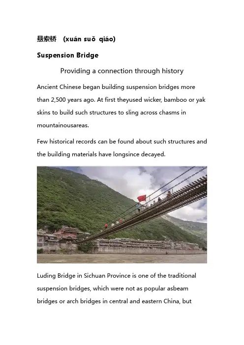
悬索桥(xuán suǒqiáo)Suspension BridgeProviding a connection through history Ancient Chinese began building suspension bridges more than 2,500 years ago. At first theyused wicker, bamboo or yak skins to build such structures to sling across chasms in mountainousareas.Few historical records can be found about such structures and the building materials have longsince decayed.Luding Bridge in Sichuan Province is one of the traditional suspension bridges, which were not as popular asbeam bridges or arch bridges in central and eastern China, butwidely built in the mountainous area ofwestern China. However, there are records of a bamboo suspension bridge built in the third century BC by LiBing (302–235 BC), a famous engineer. Located near today's Chengdu, capital of SichuanProvince. It is said this bamboo bridge was in use for more than 600 years.Iron chain suspension bridges first appeared in China during the T ang Dynasty (618–907 AD), butsuch bridges still in existence today were mostly built during the Ming Dynasty (1368–1644).In 1430, Thangtong Gyalpo (1385–1464), a great Tibetan Buddhist, architect and creator ofTibetan opera, built an iron chain bridge spanning the Yarlung Tsangpo River south of Lhasa,capital of the Tibetan Autonomous Region today. Boasting a central span of 137 meters, it was the suspension bridge with the longestunsupported span in the world at that time. The bridge's wooden plank walkway hung fromvertical poles and the planks were bound together with twisted willow and strips of yak hide.According to legends, Gyalpo, known as the "Buddha of Iron Bridges" at his time, built a total of58 iron chain suspensionbridges in his whole lifetime.The structure of Tibetan architect Thangtong Gyalpo's iron chain bridge on the Yarlung Tsangpo RiverAnother ancient iron chain suspension bridge with detailed historical records in China was theJihong Bridge, spanning the Lancang River in southwest China's Yunnan Province.It was once called the "First Bridge in Southwest China" as it sat on an ancient path leading toIndia and Myanmar.The iron chain link bridge was built in 1475, replacing a bamboo structure.With a total length of 113.4 meters and a width of 3.7 meters, the bridge was built with 18 thickiron chains and featured a span of 57.3 meters.However, the ancient bridge was washed away by floods in 1986.Another masterpiece of historic suspension bridges is the Luding Bridge. Built in 1706 in thesouthwest China's Sichuan Province, the 103-meter-long and 3-meter-wide bridge is made from13 thick iron chains with a total weight of more than 40 tons.The bridge was long regarded as a key link in connecting Sichuan Province and the Tibetanregion. But it is today also known for a fierce battle fought there by the Chinese CommunistParty-led Red Army in May 1935 against Kuomintang allied local warlords during its famous LongMarch to reach its bases in northern China.In 1961, the bridge was listed among the first batch of key cultural relics of the country and putunder state protection. Today it is a popular tourist attraction drawing throngs of visitors everyday.Though suspension bridges were not as popular as beam bridges or arch bridges in ancientChina, in the past several decades, the country has built many world-class suspension bridges tomeet its needs for modernization.The Xihoumen Bridge was built in 2009 on the Zhoushan Archipelago in east China's Zhejiang Province, witha main span of 1,650 meters.They include the Xihoumen Bridge built in 2009 on the Zhoushan Archipelago in east China'sZhejiang Province, with a main span of 1,650 meters; the Runyang Yangtze River Bridge built in2005 in east China's Jiangsu Province, with a main span of 1,490 meters; the Fourth NanjingYangtze Bridge build in 2012 also in Jiangsu Province, with a main span of 1,418 meters; and theJiangyin Yangtze River Bridge built in 1999 also in Jiangsu Province, with a main span of 1,385meters.All the four above are among the top 10 suspension bridges in the world today in terms of the length of their main spans.Pictorial dictionary·吊桥(diào qiáo) drawbridgeIn Chinese, the term diaoqiao may mean either a suspension bridge or a drawbridge. Asuspension bridge can also be called xuansuoqiao in Chinese, but the drawbridge doesn't haveanother common alias.Also, unlike in other parts of the world, where the term drawbridge may refer to a number ofmovable bridges, such as bascule bridge, vertical-lift bridge and swing bridge, in ancient China adrawbridge was used almost exclusively of the bridge installed in front of a city wall gate andspanning a surroundingmoat.Such city moat drawbridges were mostly made of wood and could be raised —particularly toprevent invading troops from entering the city.Many Chinese historians and architects believe that the first drawbridges appeared in Chinaduring the Spring and Autumn Period (770–476 BC), together with the city moat.。

附录A译文桥梁桥梁是人类征服空间的象征。
当日落时你在太平洋中看到深红色网格的金门大桥时,或者耀武扬威的在深谷上滑翔,你会感到惊奇并钦佩它们建造者的艺术。
它们是人类在追求更好更自由的世界,移除堡垒的决心的持久的证明。
他们的设计和建筑计划是像在梦里一样的想象,但是构想和决心都还不够,各种力如重力等的具体数据必须靠数学模型精确计算,这需要艺术的灵感和工匠的技术。
科学关于材料和结构的行为的知识已经明显地扩大,并且计算技术现在可广泛便捷地应用在操作复杂的理论,工程师们实际上在过去十年已经彻底改革桥设计和建设方法。
这些发展应用于短、中、长跨桥。
对于耐久的桥,最普通的材料就是用钢筋和混凝土。
不同种类的桥都是用这些材料的。
木材都是用于水上的暂时的建筑,木制短跨度桥不可设置在水平面下,现在美国已经在实验一些铝制的短跨度桥。
一座桥的主要部分可以据说是“基础”和“上层建筑”。
因为在很多桥里没有清楚的在这两个之间划分,这个划分被仅仅为了方便起见在这里使用。
基础的一般要素是桥台和墩台,它们经常分别建造基础,例如混凝土扩展基础,这些基础是基础的一部分。
偶尔有些基础是桩基础,桩伸到水平线以上,顶部有桩帽,这样可以支持主要的上部结构。
这种形式经常被用来做长的、低的、跨水的结构。
附录B英文文献BridgesBridges are great symbols of mankind’s conquest of space. The sight of the crimson tracery of the Golden Gate Bridge against a setting sun in the Pacific Ocean, or the atch of the Garabit Biaduct soaring triumphantly above the deep gorge. F ills one’s heart with wonder and admiration for the art of their builders[11]. They are the enduring expressions of mankind’s determination to remove all barriers in its pursuit of a better and freer world. Their design and building schemes are conceived in dream-like bisions. But vision and determination are not enough. All the physical forces of nature and gravity must be understood with mathematical precision and such forces have to be resisted by manipulating the right materials in the right pattern. This requires both the inspiration of an artist and the skill of an artisan.Scientific knowledge about materials and structural behavior has expanded tremendously, and computing techniques are now widely available to manipulate complex theories in innumerable ways very quickly. Engineers have virtually revolutionized bridge design and construction methods in the past decade. The advances apply to short-medium and long-span bridges.For permanent bridge,the most commonly used materials are steel and concrete. Bridge of many different type are built with these materials,used singly or in combination. Timber may be used for temporary above-water construction, for the elements of a structure that lie below the waterline (particularly timber pile s), or for short-span bridges located on secondary roads. A few short-span aluminum bridges have been built in the United States on an experimental basis.The principal portions of a bridge may be said to be the “substructure” and the “superstructure.” This division is used here simply for convenience, since in many bridges there is no clear dividing lint between the two.Common elements of the substructure are abutments (usually at the bridge ends) and piers (between the abutments).Piers and abutments often rest on separately constructed foundations such as concrete spread footings or groups of bearing piles; these foundations are part of the substructure. Occasionally a bridge substructure comprises a series of pile bents in which the piles extend above the waterline and are topped by a pile cap that, in turn, supports the major structural elements of the superstructure. Such bents often are used in arepetitive fashion as part of along, low, over-water crossing.In recent years, the dividing lines between short-medium and long-span bridge have blurred somewhat. Currently, spans of 20 to 100 ft (6.1 to 30.5m) are regarded as short by many designers, who have developed many standardized designs to handle these spans economically.Medium spans range up to, per-haps, 400ft (121.9m) in modern bridge practice, depending on the organization involved and the materials used. Long spans range up to 4000ft (1219.2m) or more, but a clear span above 1000ft (304.8m)is comparatively rare.。
Unit 1 Highway Introduction公路简介(1) Road classification道路分类Road路,道路,公路, highway公路;干道, freeway高速公路;高速干道, expressway高速公路, street街,街道,(2) Road concept道路概念Road layout道路布局,planning 城市规划,土地规划, spacing 间隔, network网状物;网状系统, location位置;场所,所在地, terrain 地形;地势, drainage排水系统,排水设备;下水道, survey 测量,勘测,测绘(3) Road structure道路结构Alignment线型surface面,表面, subgrade路基,地基curvature弯曲, (几何)曲率, gradient 坡度,倾斜度, ditch沟;壕沟,水道,渠道, turnout产量,产额,4) Materials材料Gravel 砂砾,碎石,石子dirt污物;烂泥;灰尘,泥土, soil土,泥土,土壤, asphalt沥青;柏油, cement水泥, concrete 混凝土的, 具体的Rubble毛石,块石, flag薄层,薄层砂岩, stone石,石头,石块, slab石板,厚板,平板;厚片, grout薄泥浆;水泥浆,石灰浆lime石灰, cement水泥,胶结材料Bottom layer底层/intermediate layer中间层/upper layer上层/top layer顶层The Empire帝国/ the Dark Ages黑暗时代/ the Middle Ages中世纪Topograph地形图/topography地形;地形学;地形测量学/topographic地形(学)上的Turnpike收费公路/toll system收费系统/ETC –Electronic Toll Collection电子收费3. Highway types公路类型Freeway高速公路;高速干道: freeway/expressway高速公路Controlled access highway控制进入高速公路Conventional highway传统的公路Highway公路;干道: arterial highway干线公路/bypass旁道,旁路/divided highway双向分隔行驶的公路;双向之间有分车带的公路/through street通过街/through highway通过公路Parkway停车道Scenic highway风景公路Street街,街道: Cul-de-Sac street小路尽头的街道/dead end street尽头街道/frontage street正街/local street地方街道Road路,道路,公路: frontage road街面道路/local road地方道路/toll road 收费道路(bridge桥,桥梁, tunnel隧道,地道)1. Technical termsCross section横断面/ Profile 纵断面(图),剖面(图)/Plan view平面视图Longitudinal section/ Transverse section 纵/横截面Lane/ Multilane/ Multiple lanes行车/多通道/多车道Roadway巷道Through traffic/ Local traffic/ Traffic island通过交通/交通/交通岛MedianRoadbed/ curb/ shoulder路基/ 路边,(人行道旁的)镶边石,边栏/肩Right-of-way 公路用地Surface course表面过程/ Wearing course磨损过程/ Basecourse基层/Flexible pavement柔性路面/ Rigid pavement刚性路面Cohesion凝聚力/ cohesive有粘着力的;凝聚性的;有结合力的Roadbase基层/ Subbase基层Crack/ Break/ Stress/ Distress裂纹/打破/压力/痛苦,窘迫的Modulus of elasticity弹性模量2. Main points1 Geometric Cross Section on Highway几何截面的公路上1.1 Lane巷1.2 Median位数1.3 Outer separation外部分离1.4 Roadbed路基1.5 Roadside路边1.6 Roadway巷1.7 Shoulder肩1.8 Travel way旅行方式Unit 4 Asphalt and Mix Asphalt沥青和沥青混合Technical termsMix/ mixture/ compound混合/混合物/复合Petroleum石油/ crude oil原油/ gasoline汽油/ diesel柴油/ gas可燃气;煤气;沼气/ petrol汽油Bitumen沥青/ bituminous 沥青的;含沥青的/ pitch搭(帐篷);扎(营)/asphalt沥青/ asphaltum沥青/ tar焦油;柏油,沥青Hydrocarbon碳氢化合物/ hydrau液Destructive distillation破坏性蒸馏Disulfate硫酸盐Emulsify乳化/ emulsion乳胶;乳状液/Dilute稀释/ diluents稀释剂/solvent有溶解力的/ cutter stock刀具的库存Oxygen氧,氧气/ oxidize使氧化/ oxidation 氧化(作用)/ oxidization 氧化/ dioxide二氧化物/ hydrogen氢/ sulphur硫磺Waterproof不透水的,防水的Acid/ alkalis/ salt/ alcohol酸/碱/盐/酒精Liquid/ fluid/ liquor/ liquefy液/液/液/液化Semi-solid半固态/ hard-brittle solid硬脆性固体/ water-thin liquidBinder粘结剂,捆缚(或包扎)用具;绳索,带子/ sticky粘的;涂有粘胶物质的;泥泞的/ viscous粘的/ adhesive粘的;粘着的;有粘性的/ viscosity粘质;粘性Hard-surface硬地/ hard-face硬面/ hard-surfaced road坚硬的路Tack coat粘结层Cut-back asphalt稀释沥青Penetration. 针入度Versatility多样化的/ flexibility易曲性;适应性,灵活性;弹性/ durability耐久性/ ability能力;能耐/ capacity 容量, 能力,才能,接受能力,理解力/ compactability紧/Rigidity 坚硬;严格;刚直;死板/ strength强度;(酒等的)浓度/ hardness硬性;硬度/ elastic 有弹性的,有弹力的/ rigid坚硬的;坚固的;不易弯曲的/ modules of elasticity弹性模数/Cold temperature cracking低温开裂/ warm temperature rutting高温车辙Performance 履行;实行;完成,演出/ grade等级;级别;阶段/ Performance Grading性能分级(PG)Aggregate使聚集Bin (贮藏谷物等的)箱子,容器,仓/ dryer干燥剂,催干剂/ pug mill练泥机/ drum鼓状物;圆桶/ tank (贮水,油,气等的)柜,罐,箱,槽latex乳汁;乳胶sulphur extended asphalt硫磺沥青混合料sulphur dioxide二氧化硫hydrogen sulphide硫化氢1. Technical termsStability 稳定,稳定性/ stabilize 使稳定,使稳固/availability有效;有益;可利用性/ available 可利用的,可得到的/Sense 感觉;意识;观念/ sensitivity敏感性;感受性Solubility 可溶性, 溶解度/ soluble 可溶解的/ solution溶解,解答;解决(办法); /Rutting车辙/ rust锈,铁锈;(脑子等的)迟钝;(能力等的)荒废/ tar焦油;柏油,沥青Roadstone石马路By-product副产品/ coke 焦,焦炭,焦煤/ coal gas 煤气/ kerosene煤油,火油Residue 残余,剩余,滤渣,残余物/ residual残留的;剩余的/ remain剩下,余留strengthen 加强;增强;巩固/ strength 力,力量, 强度/ deformation 毁坏;变形/ deform 使变形/ reform 改革,革新,改良elastic有弹性的,有弹力的/elasticity 弹性;弹力/plastic可塑的,塑性的/plasticity 可塑性;适应性;柔软性/chipping碎屑permanent永久的,永恒的;永远的, 固定性的;常在的/ temporary 临时的;暂时的,一时的poise使平衡;使平稳/ Dyne达因/ Newton 牛顿stiffness劲度/ stiff 硬的,僵直的,僵硬的/ stress压力;紧张;应力/ strain拉紧;拖紧;伸张/ fatigue疲劳,劳累Deduce演绎,推论/ deduction 扣除,减除,推论;演绎(法/ composition 构成;构图;成分penetration test渗透测试/ softening point test软化点试验/ ring and ball test环和球试验internal diameter 内部直径/ external diameter外部直径sample样品,样本;例子,实例/ water bath水浴arbitrary反复无常的,任性多变的;独断的,专制的/ pragmatic 实际的;实干的/ pragmatism 实用主义/fluidity 流动性;流状;易变(性)/ segregate分离/ susceptibility敏感性/ susceptible 敏感的, rheology流变学/ rheological 流变rolled asphalt碾压沥青synthetic polymer 合成聚合物/ additive附加的epoxy resin环氧树脂impart to传授/ deter威慑住,吓住;使断念/ deterrent 威慑的;遏制的container terminal集装箱码头/ airfield apron机场停机坪Unit 5 Cement and Concrete水泥和混凝土A. Technical termsCement水泥,胶结材料/ chalk粉笔/ matrix矩阵Cementitious 水泥Calcium钙/ calciferous钙/Lime石灰/ limestone石灰石Silica 硅土,二氧化硅/ silicate硅酸盐Aluminium铝/ alumina氧化铝/ aluminate铝sinter烧结coarse clinker粗水泥熟料calcium aluminate 铝酸钙/ calcium silicate硅酸钙hydrate水合物/ cure治疗/Work工作/ workable 可使用的,可运转的/ workability可使用性Shrinkage收缩/ swell膨胀/ swellable膨胀/ swellability溶胀strain拉紧;拖紧;伸张grout薄泥浆;水泥浆constituent组织/ ingredient成分/ component组成Thermal热的;热量的/ thermal coefficient of expansion热膨胀热系数Compressive strength抗压强度/ tensile strength拉伸强度Compressive压缩/ tensile 拉伸Reinforce加固/ reinforcing bar钢筋/ reinforced concrete钢筋混凝土Stiffness劲度Vulnerable脆弱的Efflorescence 风化/ weather天气/ weathering气候Column 柱/ volume体积/Pressure vessel压力容器1. Technical termsPrestress预应力Crew船员Contract 合同/ contractor承包商Resident engineer驻地工程师Inspector检查员Structural member结构构件Steel strand钢绞线Bridge girder桥主梁Pier cap墩帽Deck slab甲板Pretensioning先张法/ post-tensioning后张法Precast预制/ cast -in-place就地浇Box girder箱梁Predetermined stress预定压力Stretch拉伸/ relax 放松/ shorten 缩短/ induce诱导Duct 输送管;导管/ conduit导水管,导管/ pipe管,导管,输送管/ tube 管;筒/ canal管,道/ vessel 容器Anchor 锚/ Anchorage锚具corrosion腐蚀;侵入rebar钢筋/ reel卷轴tarpaulin 防水油布condense压缩/ condensation冷凝require要求/ requisite必要/ prerequisite不可缺的;事先需要的uniform 制服/ uniformity统一vary使多样化/ various不同的;各种各样的,形形色色的/ variable / variationcamber deflection 上弯翘起挠度creep蠕变Standard Specification 标准规范/ Sampling Guide取样指南Couple一双(对)/ coupler联结器Stir搅拌/ stirrup镫筋,箍筋/Web网络/ flange凸缘/ rib肋,肋骨/ side form形式Flimsy脆弱的Galvanize strip steel 镀锌带钢/ sheet steel钢片Weld焊接;熔接;锻接,使结合/ seam 缝;接缝,缝合处,接合口;裂缝Helical螺旋/helically螺旋形的/ helicopter直升飞机Contra-flexure反向弯曲/ parabolic curve抛物曲线Uplift隆起的Wobble摆动/ twist扭转;扭弯;旋转/ spall破碎Case事实,实例,案件/ Encase装箱Increment增加;增加量;增额Slack松弛的,不紧的;不严的Pressure gauge压力表/ load cell负载单元/ stretcher担架/ dynamometer动力计;力量计;握力计Dead end 尽头;困境/ stressing end强调结束Elongation measurement伸长测量法Spliced strand拼接链Tendon筋腱、预应力钢索、钢筋束Inject注射/ eject 逐出,轰出;喷射,吐出/ injection /ejectionVent通风孔,排气孔/ slut邋遢女子/ inlet valve入口阀Unit 6 Measuring Technology and Equipment测量技术及设备A. Technical termsSurvey测量/ surveyor测量员Horizontal/vertical/plumb/slope/ plan/plane垂直/水平/垂直/倾斜/计划/飞机Elevation高程Odometer 测距仪Circumference 圆周;周长/ circle圆/ circulate流通;传播/ circular 圆Tape带子,线带Tacheometry 视距测量Stadia 视距Theodolite /transit 经纬仪Rod 测杆、标尺Telescope望远镜Topographic survey地形测量Topographic mapping地形测绘Hydrographic mapping水文图Electronic distance measurement(EDM)电子距离测量Terrain地形;地势Electromagnetic电磁(体)的Velocity/speed速度/速度Band传送带;带,细绳Infrared/ ultraviolet 红外/紫外Module/ modulate模块/调节Passive/ active/ positive/ negative 被动/主动/积极/消极Perpendicular/ parallel 垂直/平行Clinometer / abney 测斜仪/水准仪Sextant六分仪/ sexagesimal 六十分数Compass界线;周围,圆规Protractor 量角器Unit 8 The Subgrade Design and Construction Technology路基设计与施工技术A. Technical termsUppermost / top soil 最上面/土壤Embankment / excavation路堤/挖掘Fill / cut填充/切割Foundation建立,创办;基础;基本原则Organic / inorganic / organ / organization有机/无机/机关/组织Imported soil / borrow sources进口/借用来源Dense / density / condense密/密度/凝结Moisture content含水量Classification分类;分级Differ / different / difference / differentiate不同的/不同/不同/分化Cobble / gravel / sand / silt / clay卵石/砾/砂/泥/粘土Fine grained soil细粒土Dry mass / dry matter干质量/干物质Semi-weathered半风化In-situ在原处;在原位置Infer推断Resilient modulus 回弹模量Manual 手的;手工的;用手操作的;体力的Backcalculate 反演计算Overlay覆盖;铺在...上面;镀;压倒Prototype原型;标准;模范Frost冰冻/ thaw融化,融解/ heave举起,拉起, /Guide / guidance / guideline指导/指南/指导方针Expansive soil 膨胀土Bentonitic shale 膨胀土页岩Soil modifier土壤改良剂Culvert阴沟;地下电缆管道;涵洞桥Form / formulate / formulation / formula形式/制定/公式化;规划;构想/公式Title——Highway Subgrade Construction公路路基施工1. Technical termsExcavation挖掘;开凿Borrow pit借土坑Sidestep回避Borrow ditch借沟Dispose / disposal处理/处置Surplus material剩余材料Approach接近,靠近Conforming / nonconforming material合格/不合格材料Top soil / superficial coatTurf 草皮土壤/表层stake mark危险标记subgrade edge路基边缘top of slope / foot of slope顶坡/坡脚berm 便道peg 桩facility 设施silt 泥沙,淤泥/ scour 冲刷permeable有渗透性的;可穿过的/ torrent 急流earthwork 土方量over-excavation挖blast 爆炸,爆破/ fetch soil 取土transverse 横向的;横断的;横切的/ longitudinal excavation纵向开挖hauling牵引backfill 回填self-dumper 自卸车segment / segmental部分;线段side wall侧壁rock filling填石/ borrow filling 借方填筑compaction machine压实机/ rolling passes碾压cut off切断;中断provided 以...为条件;假如(that)bench长凳;长椅;法官席;法官;法庭tamp / tamper 夯具Unit 9 Pavement Design and Construction Technology 路面设计与施工技术A. Technical termsSkid / skidding 打滑/集材/拖曳Free-draining自由排水Standing water站在水Imported/treated material进口/处理材料Platform平台,台Bound/unbound material绑定/绑定材料Bitumen-based material沥青基材料Unbound granular material松散颗粒材料Ingress入口Regular / Regularity /regulate定期/规律/调节Permeable / impermeable / permeability 渗透/渗透/渗透impermeability不渗透性Texture组织,结构,质地Tolerance忍耐,忍耐力;宽容,宽大Deep-seated 根深蒂固/由来已久/顽固的Remedy / remedial / diagnose药物/治疗/诊断Propagate / Propagation / propaganda路床面宣传/传播/宣传Formation 形态,结构Deem 认为Clear-cut 轮廓鲜明的/ 清晰的/ 皆伐Onset 开始Design life设计寿命Roadwork道路工程Discount折扣;打折扣1. Technical termsMacadam碎石Impetus 动力/推动Rubble瓦砾Avenue / street / road 路/街/路Stone Matrix Asphalt (SMA) 沥青玛蹄脂碎石混合料Sprayer喷雾器Gritting machine 铺砂机Mixing plant搅拌设备Spreader散布者;(涂奶油用的)奶油刀Paver摊铺机Roller 滚动物;滚柱;滚筒;滚轴Road binder道路粘合剂Guss asphalt/concrete 摊铺地沥青/混凝土Stone quarry 采石场Wear and tear磨损Unit 10 Highway Alignment Design 公路线形设计A. Technical termsHorizontal/vertical alignment水平/垂直对齐Configuration. 结构;表面配置Safe operating speed安全操作速度Sight distance视距Highway capacity / traffic volume公路容量/交通量tangent正切;切线Superelevation 超高Rate of grade change速度等级变化Horizontal/vertical curve 水平/垂直曲线criteria(判断、批评的)标准,准则,尺度simple circular curve简单的圆曲线spiral transition curve 螺旋缓和曲线compound curve 复合曲线sharp curve锐曲线sharp/slight curvature 急剧的;锋利的;尖的/轻微弯曲swept path扫路centerline. 中线runoff决赛;终投票outline外形;轮廓minimum curve radii最小曲线半径long / length / lengthen长/长度/延长reverse curve 反向曲线superelevation transition超高过渡providing / provided (that) 假如…urban / suburban / rural城市/郊区/农村stopping/passing sight distance停止/超车视距multiple decision point多个决策点sight line瞄准线middle ordinate 中距/正矢no-passing zone禁区1. Technical termsGrade line分数线Crest/sag vertical curve嵴/凹形竖曲线Auxiliary lane辅助车道Maximum/minimum grade最高/最低等级Detrimental有害的warp使变形;使弯曲;Standpoint观点Climbing lane爬坡车道Offset补偿;抵消Ramp exit gore匝道出口高尔Headlight beam前照灯光束Encroach侵犯Ponding water积水Water table地下水位Pavement box路面盒Prism棱柱(体),角柱(体)Balance point平衡点Unit 14 Bridge Introduction 桥梁简介A. Technical termsPipeline / cycle track / pedestrian管道/周期轨道/行人Superstructure / substructure上层建筑/结构Single storey building单层建筑物Handrail扶手/ guardstone守护石Bearing 关系,关联;举止,风度;体态Plan view平面视图Pier墩,墩/abutment桥墩;桥基;桥台;毗邻;接界处/wingwall翼墙/approach接近,靠近/apron 裙板Rivetment 固结Masonry石造工程;石造建筑Retaining wall挡土墙Subsoil / Earthfill地基/填土Well foundation 井筒基础Footpath小径,(乡间)小路Parapet wall 栏杆、女儿墙Topple 倾覆Buckle 受弯屈服Arch bridge 拱桥/Three Gorge三峡/ span墩距;跨度slab bridge / 板桥T-beam T梁bow string girder bridge 弓弦梁桥suspension bridge吊桥Cable-stayed bridge斜拉桥steel bridge桥梁钢rainbow bridge彩虹桥Niagara river 尼亚加拉河Shutter百叶窗;活动遮板Head room头部空间Tie beam系梁Thrust用力推;刺;插;塞;挤出(路)Arch rib 拱肋Suspender / stay吊带/保持Tower塔;塔楼;高楼Orthotropic deck正交异性桥面Continuous girder连续梁Three-dimensional三维Stiffening girder加劲梁Transverse/longitudinal/radial bracing横向/纵向/径向支撑Moment of inertia转动惯量Truss bridge桁架桥Rigid frame bridge刚构桥Axial force轴向力Portal frame门架Clearance清除,清扫;出空;空地;空隙Spandrel braced arch 腹拱、肩拱Trussed arch桁架拱桥1. Technical termsInclement恶劣的Investigation / FBI调查/调查局Reconnaissance侦察;勘察;事先考查Feasibility可行性;可能性Right angle直角Erosion侵蚀;腐蚀Whirl / cross current / scour旋转/交叉电流/冲刷render给予,提供;使得,使成为inerodable strata地层High Flood Level(HFL)高水位Discharge排出(液体,气体等);允许...离开;释放;解雇Waterway航道Pier thickness桥墩厚度High flood大洪水Current meter电流表Velocity rod流速杆Free board自由板Catchment area汇水盆地,汇水区域Watershed转折点;关键时刻;流域Boring 钻孔、钻探Rainfall降雨,下雨;降雨量Span墩距;跨度Culvert涵洞桥Ordinary Flood Level(OFL)普通洪水水位Low Water Level(LWL)低水位Afflux 雍水Head room头部空间Viaduct 高架桥Trestled bent栈桥弯曲Causeway 漫水桥Submersible潜水Cross-drainage横向排水Temporary/ permanent bridge临时/永久性桥Deck/through/semi-through bridge上/下/中承式桥Formation 建造、路床面Pony小马;小型的东西Headway进展Vertical lift bridge 垂直升降桥Bascule bridge开合式桥Swing bridge 旋开式桥Box/pipe/arch culvert盒/管/拱涵Cast iron铸铁;生铁Bearing capacity承载能力Earth cushion地垫Unit 15 Bridge Superstructure桥梁上部结构A. Technical termsWeight limit重量限制supplier供应者Span Arrangement跨径布置Bridge Project Manager大桥项目经理Redundant多余的,过剩的specification 规格;明细单;详细计划书Fracture critical骨折的关键Collapse倒塌;崩溃,瓦解Ability / Inability能力/能力Bolt螺栓stringer纵梁;纵桁span / single-span / multi-span跨度/单跨/连栋continuous spans连续跨越steel/concrete superstructure bridge钢筋混凝土桥梁rolled beam 辊压梁cover plate盖板welded plate girder焊接板梁box girder 箱梁truss扎,捆,缚,绑;用构架支撑cable stayed斜拉tied arch 系杆拱桥vertical/inclined web垂直/斜腹板top/bottom flange plate顶部/底部法兰盘hollow rectangular/trapezoidal section空心的矩形/梯形截面aesthetics美学torsional resistance扭阻力curved bridge曲线桥stringer / floor beam斯特林格/地板梁top/bottom chord顶部/底部和弦vertical/diagonal member垂直/斜成员lateral/sway bracing侧/斜撑axial load/force轴向载荷/力量concrete deck / steel girder混凝土桥面/钢大梁Box beam箱梁Strongback定位板Fabricate / fabrication / fabricator制造/生产/制造Balanced cantilever平衡悬臂Strain gage应变计Homogeneity / non-homogeneity 均匀/非均匀性Erratic 不定、无规律的Deflection偏斜;偏向;挠曲;偏度;挠度Mid-span / middle span / side span跨中/ 中跨/ 边跨Yield出产;结出(果实);产生(效果,收益等)Non-linearity非线性的Prescribe规定,指定Limiting strain极限应变flexure弯曲;弯曲部分,曲率neutral axis中性轴centroid距心lever arm杠杆臂resultant compression/tension/force/load由此产生的压缩/拉伸/ /载荷equivalent stress block等效应力块investigation / FBI调查/调查局under-reinforced / over-reinforced少筋/ 超筋stress intensity应力强度product产品,产物;产量;出产nomenclature学术用语;术语表Unit 16 Bridge Substructure桥梁下部结构A. Technical termsCap-and column type pier柱式墩帽Strut 支撑、加固T-type pierT型Hammerhead pier锤头码头Taper逐渐减少;逐渐变弱Rectangular/oval column矩形或椭圆柱Wall type pier墙式墩Strut and tie model拉压杆模型footing(稳固的)地位;基础single column/multi-column单/多列concentrated load集中荷载wall abutment墙台caisson 沉箱gutter 槽stepped/terraced wall configuration加强/梯田壁配置stub abutment直式桥台integral abutment整体式桥台wingwall 翼墙bridge seat 桥座backwall 背墙stem柄,把,杆approach slab 搭板contour轮廓;轮廓线;外形;结构1. Technical termsSpread footing扩展基础Cofferdam 围堰Negative skin friction / downdrag force负摩/下拉荷载力Friction pile摩擦桩End bearing pile端承桩Drilled caisson钻孔灌注Constructibility可构成性Embedment嵌入Casing箱;盒Confinement curbing约束控制Wire mesh basket 网笼Gabion 枝条筐streambed河床Unit 20 ——Construction Management and Cost Estimate 施工组织与概预算A. Technical termsSchedule 进度表Event / task / action /activity活动/任务/行动/活动Ultimate disposition 最后安排Expense / expenditure / cost费用/费用/成本Recast重铸Uncertainty不确定;不确信;易变;不可靠Production rate / productivity生产效率/生产力Gantt chart / bar chart甘特图表/图表Superimpose叠加Critical Path Method (CPM)关键路径法Critical task关键任务Logic diagram逻辑图Superintendent监督人,监管者Activity-on-the-arrow (AOA)活动箭Activity-on-the-node (AON)节点活动Dummy activity 虚拟工序Early start time / late start time开始时间早/晚开始时间Early finish time / late finish time最早完成时间/最晚完成时间Double line / bold line / color highlighted line / dash line双行线/颜色/大胆突出线/虚线Float / total float / free float 浮动/总时差/自由浮动interfering float 时差Preceding activity / succeeding activity前面的活动/后继活动Title——Construction Cost Estimate 建筑成本预算1. Technical termsBreakdown故障,损坏,崩溃;破裂Parameter / parametric参数/参数Direct/indirect cost直接/间接成本Finance / budget财务/预算Craftman钱包Scheme / schematic计划/方案Unit cost/price单位成本/价格Lump sum总金额Site visit网站访问Checklist核对用的清单Take-off脱下;移去;起飞;休假Overhead / profit / bond费用/利润/债券Escalation / contingence升级/偶然Shift 转移;替换,推卸Craft行业,职业Ownership and operating cost所有权和经营成本Dozer / bulldozer推土机/推土机Vendor 卖主Tax税;税金Markup 售价Similarity / dissimilarity相似/相异Unit 21 Tendering and Contract 投标与合同A. Technical termsTender敏感的,嫩的;柔软的;温柔的,体贴的Bid / bidder招标投标Agreement同意,一致;协定,协议Bond结合力;联结,联系Insurance保险;保险契约Makeup补足;编造;组成Owner / architect / designer / supplier / party业主/建筑师/设计师/供应商/派对Public agency / private company公共部门/私营公司Responsibility职责,任务;义务,负担General/special/technical provision一般/特殊/技术discretion判断力;辨别力;谨慎,考虑周到addenda补遗;追加;附加物Title——Types of construction contracts and bonds建筑合同和担保的类型1. Technical termsNegotiation / renegotiation协商/谈判Arctic / Antarctic北极/南极Cost plus a fixed fee成本加固定费用Cost plus a percentage成本加百分比Incentive刺激;鼓励;动机Thrifty 节约Innovation革新,改革,创新Compensate补偿,赔偿;酬报Procure 获得、实施Popular / popularity / population流行/流行/人口Recoup 收回surety / obligee担保/债权人forfeiture 没收、罚金penal / penalty刑法/处罚underwrite / constraint认购/约束default 违约option选择;选择权;选择自由lien 扣留权、留置权。


桥梁设计外文翻译文献桥梁设计外文翻译文献(文档含中英文对照即英文原文和中文翻译) 原文:A Bridge For All CenturiesAn extremely long-and record setting-main span was designed for the second bridge to across the Panama Canal in order to meet the owner’s requirement that no piers be placed in the water.Because no disruption of canal traffic was permitted at any time,the cable-stayed bridge of cast-in-place cancrete was carefully constructed using the balanced-cantilever method.In 1962 ,the Bridge of Americas(Puente de las America) opened to traffic,serving as the only fixed link across the Panama Canal .The bridge was designed to carry 60,000 vehicles per day on four lanes, but it has beenoperating above its capacity for many years.Toalleviate bottlenecks on the route that the bridge carries over the canal-the Pan-AmericanHighway(Inter-American Highway)-and promotegrowth on the western side of Panama,the country’s Ministry of Public Works(Ministerio de Obras Publicas,or MOP )decided to build a new highway systerm linking the northern part of Panama City,on the eastern side of the canal, to the town of Arraijan,located on the western side of the canal.The Centennial Bridge –named to commemorate 100 years of Panamanian independence-has noe been constructed and, when opend, will carry six lanes of traffic. This cable-stayed bridge of cast-in-place cancrete features a main span of 420m,the longest such span for this type of bridge in the Western Hemisphere.In 200 the MOP invited international bridge design firms to compete for the design of the crossing, requesting a two-package proposal:one techinical, the other financial. A total of eight proposals were received by December 2000 from established bridge design firms all over the world. After short-listing three firms on the basis of the technical merits of their proposals, the MOP selected T.Y.Lin International, of San Francisco, to prepare the bridge design and provide field construction support based on the firm’s financial package.The Centennial Bridge desige process was unique and aggressive,incorporating concepts from the traditional design/build/bid method, the design/build method , and the sa-called fast-track design process.T o complete the construction on time-that is ,within just 27 months-the design of the bridge was carried out to a level of 30 percent before construction bidding began, in December 2001.The selected contractor-the Wiesbaden,Germany,office of Bilfinger Berger,AG-was brought on board immediately after being selected by the MOP ,just as would be the case in a fast-track approach. The desige of the bridge was then completed in conjunction with construction , a process that id similan to desige/build.The design selected by the client features two single-mast towers,each supporting two sets of stay cables that align in one vertical plane.Concrete was used to construct both the towers and the box girder deck,as well as the approach structures.The MOP , in conjunction with the Panama Canal Authority,established the following requirements for the bridge design :A 420m,the minimum length for the main span to accommodate the recently widened Gaillard Cut,a narrow portion of the canal crossing the Continental Divide that was straightened and widened to 275m in 2002;A navigational envelope consisting of 80m of vertical clearance and 70mof horizontal clearance to accommodate the safe passage of a crane of World War 11 vintage-a gift from the /doc/e5324711c381e53a580216fc700abb 68a982ad21.html ernment that is used by the Panama Canal Authority to maintain the canal gates and facilities;A roadway wide enough to carry six lanes of traffic, three in each direction;A deck able to accommodate a 1.5m wide pedestrian walkway;A design that would adhere to the American Association of State Highway and Transportation Official standard for a 100-year service life and offer HS-25 truck loading;A structure that could carry two 0.6m dianeter water lines;A construction method that would not cross the canal at any time or interrupt canal operationa in any way.Because of the bridge’s long main span and the potential for strong seismic activity in the area,no single building code covered all aspects of the project.Therefore the team from T.Y. Lin International determinded which portions of several standard bridge specifications were applicable and which were not.The following design codes were used in developing the design criteria for the bridge,it is standard specifications for highway bridge ,16th ed,1996It was paramount that the towers of the cable-stayed structucture be erected on land to avoid potential ship collision and the need to construct expensive deep foundation in water. However, geological maps and boring logs produced during the preliminary design phrase revealed that the east and west banksof the canal, where the towers were to be located, featured vastly different geologicaland soil conditions. On the east side of the canal, beneath shallow layers of overburden that rangs in consistency from soft to hard, lies a block of basalt ranging from medium hard to hard with very closely spaced joint.The engineers determined that the basalt would provide a competent platform for the construction of shallow foundation for tower, piers, and approach structures on this side of bridge.The west side, however,featured the infamous Cucaracha Formation, which is a heterogeneous conglomerate of clay shale with inclusions of sandstone, basalt,and ash that is prone to landslide. As a sudsurface stratum the Cucaracha Formation is quite stable,but it quickly erodes when exposed to the elements. The engineers determined that deep foundations would therefore be needed for the western approach structure,the west tower,and the western piers.Before a detailed design of the foundationa could be developed,a thorough analysis of the seismic hazards at the site was required,The design seismic load for the project was developed on the basis of a probabilistic seismic hazard assessment that considered the conditions at the site.Such an assessment establishes the return period for a given earthquake and the corresponding intensity of ground shaking in the horizontal directtion in terms of an acceleration response spectrum.The PSHA determined two dominant seismic sources: a subduction source zone associated with the North Panama Deformed Belt capable of producing a seimic event as strong as 7.7MW,and the Rio Gatun Fault, capable of producing an event as strong as 6.5MW.The 7.7MW NPDB event was used as the safety evluationearthquake,that is,the maximum earthquake that could strike without putting the bridge out of service.The damage to the bridge would be minor but would require some closures of the bridge.The 6.5MWRio Gatun Fault event was used as the foundational evaluation earthquake,a lower-level temblor that would cause minimal damage to the bridge and would not require closures.For the FEE load case,the SEE loading was scaled back by two-thirds.The FEE is assumed to have a peak acceleration of 0.21g and a return period of 500 years; the probability that it will be exceeded within 50 years is 10 pencent and within 100 years,18 persent.The SEE is assumed to have a peak acceleration of 1.33g and a return period of 2,500 years;the probability that it will be exceeded within 50 years is 2 pencent and within 100 years,4 persent.Because of uncertainty about the direction from which the seismic waves would approach the site, a single response spectrum-a curve showing the mathematically computed maximum response of a set of simple damped harmonic oscillators of different natural frequencies to a particular earthquake ground acceleration-was used to characterize mitions in two mutually orthogonal directions in the horizontal plane.To conduct a time-history analysis of the bridge’s multiple supports,a set of synthetic motions with three components-longitudinal,transverse,and vertical-was developd using an iterative technique.Recorded ground motions from an earthquake in Chile in 1985 were used as “seed”motions for the sythesis process.A time delay estimate-that is,an estimate of the time it would take for the motions generated by the SEEand FEE earthquakes to travel from one point to the next-was create using theassumed seismic wave velocity and the distance between the piers of the /doc/e5324711c381e53a580216fc700abb 68a982ad21.html ing an assumed was velocity of approximately 2.5km/s,a delay on the order of half a second to a secondis appropriate for a bridge 1 to 2km long.Soil-foundation interaction studies were performed to determine the stiffness of the soil and foundation as well as the seismic excitation measurement that would be used in the dynamic analyses.The studieswere conducted by means of soil-pile models using linear and nonlinear soil layera of varying depths.The equivalent pile lengths in the studies-that is, the lengths representing the portions of a given pile that would actually be affected by a given earthquake-induced ground motion-ranged from2to10m.In such a three-dimensional model,there are six ways in which the soil can resist the movement of the lpile because of its stiffness:throngh axial force in the three directions and through bending moments in three directions.Because the bridge site contains so many layers of varying soil types,each layer had to be represented by a different stiffness matrix and then analyzed.Once the above analyses were completed,the T.Y.Lin International engineers-taking into consideration the project requirements developedby the owener-evaluated several different concrete cable-stayed designs.A number of structural systems were investigated,the main variables,superstructure cross sections,and the varying support conditions described above.The requirement that the evevation of the deck be quite high strongly influenced the tower configuration.For the proposeddeck elevation of more than 80m,the most economical tower shapes included single-and dual-mast towers as well as “goa l post”towers-that is,a design in which the two masts would be linked to each other by crossbeams.Ultimately the engineers designd the bridge to be 34.3m wide with a 420mlong cable-stayd main span,two 200mlong side spans-one on each side of the main span-and approach structures at the ends of the side spans.On the east side there is one 46m long concrete approach structure,while on the west side there are three,measuring 60,60,and 66m,for a total bridge length of 1,052m.The side spans are supported by four piers,referred to,from west to east,as P1.P2,P3,and P4.The bridge deck is a continuous single-cell box girder from abutment to abutment; the expansion joints are located at the abutments only. Deck movements on the order of 400 mm are expected at these modular expansion joints Multidirectional pot bearings are used at the piers and at the abutments to accommodate these movements.The deck was fixed to the two towers to facilitate the balanced-cantilevermethod of construction and to provide torsional rigidity and lateral restraint to the deck.. Transverse live loads, seismic loads, and wind loads are proportionally distributed to the towers and the piers by the fixity of the deck to the towers and by reinforced-concrete shear keys located at the top of P1, P3, and P4. The deck is allowed to move longitudinally over the abutments and piers. The longitudinal, seismic, live, and temperature loads are absorbed by what is known as portal frame structural behavior, whereby the towers and the deck form a portal-much like the frame of a door in a building-that acts in proportion to therelative stiffness of the two towers.As previously mentioned, the presence of competent basalt on the east side of the site meant that shallow foundations could be used there; in particular, spread footings were designed for the east tower, the east approach structure, and the east abutment. The west tower, the west approach structure, and the western piers (P2 and P3), however, had to be founded deep within the Cucaracha Formation. A total of 48 cast-in-drilled-hole (CIDH) shafts with 2 m outer diameters and lengths ranging from 25 to 35 m were required. A moment curvature analysis was performed to determine the capacity of the shafts with different amounts of longitudinal steel rebar. The results were plotted against the demands, and on the basis of the results the amount of required longitudinal reinforcing steel was determined to be 1 percent of the amount of concrete used in the shafts. The distribution of the longitudinal reinforcing steel was established by following code requirements, with consideration also given to the limitations of constructing CIDH piles with the contractor’s preferred method, which is the water or slurry displacement method.A minimum amount of transverse steel had to be determined for use in the plastic regions of the shaft-that is, those at the top one-eighth of eighth of each shaft and within the shaft caps, which would absorb the highest seismic demands. Once this amount was determined, it was used as the minimum for areas of the shafts above their points of fixity where large lateral displacements were expected to occur. The locations of the transverse steel were then established by following code requirements and by considering the construction limitations of CIDH piles. The transverse steel was spiral shaped.Even though thief foundation designs differed, the towers themselves were designed to be identical. Each measures 185.5 m from the top of its pile cap and is designed as a hollow reinforced-concrete shaft with a truncated elliptical cross section (see figure opposite). Each tower’s width in plan varies along its height, narrowing uniformly from 9.5 m at the base of the tower to 6 m at the top. In the longitudinal direction, each pylon tapers from 9.5 m at the base to about 8 m right below the deck level, which is about 87 m above the tower base. Above the deck level the tower’s sections vary from 4.6 m just above the deck to 4.5 m at the top. Each tower was designed with a 2 by 4 m opening for pedestrian passage along the deck, a design challenge requiring careful detailing.The towers were designed in a accordance with the latest provisions of the ATC earthquake design manual mentioned previously (ATC-32). Owing to the portal frame action along the b ridge’s longitudinal axis, special seismic detailing was implemented in regions with the potential to develop plastic hinges in the event of seismic activity-specifically, just below the deck and above the footing. Special confining forces and alternating open stirrups-with 90 and 135 degree hooks-within the perimeter of the tower shaft.In the transverse direction, the tower behaves like a cantilever, requiring concrete-confining steel at its base. Special attention was needed at the joint between the tower and the deck because of the central-plane stay-cable arrangement, it was necessary to provide sufficient torsional stiffness and special detailing at the pier-to-deck intersection. This intersection is highly congested with vertical reinforcing steel, the closely spaced confining stirrups of the tower shaft, and the deck prestressing andreinforcement.The approach structures on either side of the main span are supported on hollow reinforced-concrete piers that measure 8.28 by 5 m in plan. The design and detailing of the piers are consistent with the latest versions of the ATC and AASHTO specifications for seismic design. Capacity design concepts were applied to the design of the piers. This approach required the use of seismic modeling with moment curvature elements to capture the inelastic behavior of elements during seismic excitation. Pushover analyses of the piers were performed to calculate the displacement capacity of the piers and to compare them with the deformations computed in the seismic time-history analyses. To ensure an adequate ductility of the piers-an essential feature of the capacity design approach-it was necessary to provide adequate concrete-confining steel at those locations within the pier bases where plastic hinges are expected to form.The deck of the cable-stayed main span is composed of single-cell box girders of cast-in-place concrete with internal, inclined steel struts and transverse posttensioned ribs, or stiffening beams, toward the tops. Each box girder segment is 4.5 m deep and 6 m long. To facilitate construction and enhance the bridge’s elegant design, similar sizes were used for the other bridge spans. An integral concrete overlay with a thickness of 350 mm was installed instead of an applied concrete overlay on the deck. In contrast to an applied overlay, the integral overlay was cast along with each segment during the deck erection. Diamond grinding equipment was used to obtain the desired surface profile and required smoothness. The minimum grinding depth was 5 mm.A total of 128 stay cables were used, the largest comprising83 monostrands. All cables with a length of more than 80 m were equipped at their lower ends with internal hydraulic dampers. Corrosion protection for the monostrands involved galvanization of the wires through hot dipping, a tight high-density polyethylene (HDPE) sheath extruded onto each strand, and a special type of petroleum wax that fills all of the voids between the wires.The stays are spaecd every 6 m and are arranged in a fan pattern.They are designed to be stressed from the tower only and are anchored in line with a continuous stiffening beam at the centerline of the deck.The deck anchorage system is actually a composite steel frame that encapsulates two continous steel plates that anchor the stays and transfer the stay forces in a continuous and repetitive system-via shear studs-throuthout the extent of the cable-supported deck (see figure above).A steel frame was designed to transfer the stays’horizontal forces to the box girders through concrete-embedded longitudinal steel plates and to transfer the boxes’ vertical forces directly through the internal steel struts.This innovative and elegant load transfer system made rapid construction of the concrete deck segments-in cycles of three to five days-possible.In addition to the geotechnical and seismic analyses,several structural analyses were performed to accurately capture the behavior of this complex bridge.For the service-load analysis,which includes live,temperature,and wind loads,the engineers used SAP2000, a computer program created and maintained by Computers &Structrures,Inc.(CSI), of Berkeley, California.This program was selected for its ability to easily model the service loads and to account for tridimensional effects.For correct SAP2000 modeling,it was necessary to define a set of initial stresses on the cables, deck, and tower elements to capture the state of the structure at the end of construction.For the calculation of those initial stresses, a series of iterations on the basic model were performed to obtain the stay forces in the structure that balance both the bridges’s self-weight and the superimposed dead loads. Once the correct cable stiffness and stress distribution were obtained, all subsequent service-load analyses were performed to account for the geometric stiffness and P-deltaeffects, which consider the magnitude of an applied load (P) versus the displacement(delta).The seismic analysis of the structure was conducted using the SADSAP structural analysis program, also a CSI product, based on the differences in seismic motions that will be experienced at the different piers based on their distance from one another.This sophisticated program has the capability to model inelastic behavior in that flexural plastic hinges can readily be simulated.Plastic hinge elements were modeled at varous locations along the structure where the results from a preliminary response spectrum analysis in SAP2000 indicated that inelastic behavior might be expected.The time-history records pertaining to the site were used in conjunction with the SADSAP model to botain a performace-based design of the piers and towers and to verifh the design of several deck stctions.As previously mentioned,the construction contractor was brought on board earl y in the process;the company’s bid of $93 million was accepted and the project was awarded in March 2002.To guarantee unimpeded canal traffic,the bridge had to be constructed without the use of the canal waters.To accomplish this, the cast-in-place main-pain superstructure was erected using the balanced-cantilever method.Form travelers were usedto accomplish this, and they were designed in such a way that they could be used as an integral part of the pier tables’falsework.After assembly on the ground, two 380 Mg form travelers were raised independently into the pier table casting position and connected to each other.After an initial learning period, the contractor was able to achieve a four-day cycle for the casting of the cantilevered deck segments, an achievement that greatly enhanced the ability of the team to construct the project on time.Once the side-span and mai-span closures were cast, the travelers had to be removed from locations adjacent to the towers rather than over water so as to avoid any influence on canal traffic.To save time, the towers approach structure, and piers were built simultaneously.The approach viaducts were designed and built using the span-by-span erection method by means of an underslung suupport truss.The east viaduct span was built first and the support truss was then removed and transferred to the west side so that it could be used to build the three spans of the west viaduct, one span at a time.The bridge construction was completeed in Auguse 2004 at a cost of approximately $2,780 per square meter.Its opening awaits the completion of the rest of the highway it serves.跨越世纪之桥1962年,横跨巴拿马运河的美国大桥作为仅有的固定连接开放交通车。
桥梁设计外文翻译文献(文档含中英文对照即英文原文和中文翻译) 原文:A Bridge For All CenturiesAn extremely long-and record setting-main span was designed for the second bridge to across the Panama Canal in order to meet the owner’s requirement that no piers be placed in the water.Because no disruption of canal traffic was permitted at any time,the cable-stayed bridge of cast-in-place cancrete was carefully constructed using the balanced-cantilever method.In 1962 ,the Bridge of Americas(Puente de las America) opened to traffic,serving as the only fixed link across the Panama Canal .The bridge was designed to carry 60,000 vehicles per day on four lanes, but it has beenoperating above its capacity for many years.Toalleviate bottlenecks on the route that the bridge carries over the canal-the Pan-AmericanHighway(Inter-American Highway)-and promotegrowth on the western side of Panama,the country’s Ministry of Public Works(Ministerio de Obras Publicas,or MOP )decided to build a new highway systerm linking the northern part of Panama City,on the eastern side of the canal, to the town of Arraijan,located on the western side of the canal.The Centennial Bridge –named to commemorate 100 years of Panamanian independence-has noe been constructed and, when opend, will carry six lanes of traffic. This cable-stayed bridge of cast-in-place cancrete features a main span of 420m,the longest such span for this type of bridge in the Western Hemisphere.In 200 the MOP invited international bridge design firms to compete for the design of the crossing, requesting a two-package proposal:one techinical, the other financial. A total of eight proposals were received by December 2000 from established bridge design firms all over the world. After short-listing three firms on the basis of the technical merits of their proposals, the MOP selected T.Y.Lin International, of San Francisco, to prepare the bridge design and provide field construction support based on the firm’s financial package.The Centennial Bridge desige process was unique and aggressive,incorporating concepts from the traditional design/build/bid method, the design/build method , and the sa-called fast-track design process.To complete the construction on time-that is ,within just 27 months-the design of the bridge was carried out to a level of 30 percent before construction bidding began, in December 2001.The selected contractor-the Wiesbaden,Germany,office of Bilfinger Berger,AG-was brought on board immediately after being selected by the MOP ,just as would be the case in a fast-track approach. The desige of the bridge was then completed in conjunction with construction , a process that id similan to desige/build.The design selected by the client features two single-mast towers,each supporting two sets of stay cables that align in one vertical plane.Concrete was used to construct both the towers and the box girder deck,as well as the approach structures.The MOP , in conjunction with the Panama Canal Authority,established the following requirements for the bridge design :A 420m,the minimum length for the main span to accommodate the recently widened Gaillard Cut,a narrow portion of the canal crossing the Continental Divide that was straightened and widened to 275m in 2002;A navigational envelope consisting of 80m of vertical clearance and 70mof horizontal clearance to accommodate the safe passage of a crane of World War 11 vintage-a gift from the ernment that is used by the Panama Canal Authority to maintain the canal gates and facilities;A roadway wide enough to carry six lanes of traffic, three in each direction;A deck able to accommodate a 1.5m wide pedestrian walkway;A design that would adhere to the American Association of State Highway and Transportation Official standard for a 100-year service life and offer HS-25 truck loading;A structure that could carry two 0.6m dianeter water lines;A construction method that would not cross the canal at any time or interrupt canal operationa in any way.Because of the bridge’s long main span and the potential for strong seismic activity in the area,no single building code covered all aspects of the project.Therefore the team from T.Y. Lin International determinded which portions of several standard bridge specifications were applicable and which were not.The following design codes were used in developing the design criteria for the bridge,it is standard specifications for highway bridge ,16th ed,1996It was paramount that the towers of the cable-stayed structucture be erected on land to avoid potential ship collision and the need to construct expensive deep foundation in water. However, geological maps and boring logs produced during the preliminary design phrase revealed that the east and west banks of the canal, where the towers were to be located, featured vastly different geologicaland soil conditions. On the east side of the canal, beneath shallow layers of overburden that rangs in consistency from soft to hard, lies a block of basalt ranging from medium hard to hard with very closely spaced joint.The engineers determined that the basalt would provide a competent platform for the construction of shallow foundation for tower, piers, and approach structures on this side of bridge.The west side, however,featured the infamous Cucaracha Formation, which is a heterogeneous conglomerate of clay shale with inclusions of sandstone, basalt,and ash that is prone to landslide. As a sudsurface stratum the Cucaracha Formation is quite stable,but it quickly erodes when exposed to the elements. The engineers determined that deep foundations would therefore be needed for the western approach structure,the west tower,and the western piers.Before a detailed design of the foundationa could be developed,a thorough analysis of the seismic hazards at the site was required,The design seismic load for the project was developed on the basis of a probabilistic seismic hazard assessment that considered the conditions at the site.Such an assessment establishes the return period for a given earthquake and the corresponding intensity of ground shaking in the horizontal directtion in terms of an acceleration response spectrum.The PSHA determined two dominant seismic sources: a subduction source zone associated with the North Panama Deformed Belt capable of producing a seimic event as strong as 7.7MW,and the Rio Gatun Fault, capable of producing an event as strong as 6.5MW.The 7.7MW NPDB event was used as the safety evluation earthquake,that is,the maximum earthquake that could strike without putting the bridge out of service.The damage to the bridge would be minor but would require some closures of the bridge.The 6.5MWRio Gatun Fault event was used as the foundational evaluation earthquake,a lower-level temblor that would cause minimal damage to the bridge and would not require closures.For the FEE load case,the SEE loading was scaled back by two-thirds.The FEE is assumed to have a peak acceleration of 0.21g and a return period of 500 years; the probability that it will be exceeded within 50 years is 10 pencent and within 100 years,18 persent.The SEE is assumed to have a peak acceleration of 1.33g and a return period of 2,500 years;the probability that it will be exceeded within 50 years is 2 pencent and within 100 years,4 persent.Because of uncertainty about the direction from which the seismic waves would approach the site, a single response spectrum-a curve showing the mathematically computed maximum response of a set of simple damped harmonic oscillators of different natural frequencies to a particular earthquake ground acceleration-was used to characterize mitions in two mutually orthogonal directions in the horizontal plane.To conduct a time-history analysis of the bridge’s multiple supports,a set of synthetic motions with three components-longitudinal,transverse,and vertical-was developd using an iterative technique.Recorded ground motions from an earthquake in Chile in 1985 were used as “seed”motions for the sythesis process.A time delay estimate-that is,an estimate of the time it would take for the motions generated by the SEEand FEE earthquakes to travel from one point to the next-was create using the assumed seismic wave velocity and the distance between the piers of the ing an assumed was velocity of approximately 2.5km/s,a delay on the order of half a second to a secondis appropriate for a bridge 1 to 2km long.Soil-foundation interaction studies were performed to determine the stiffness of the soil and foundation as well as the seismic excitation measurement that would be used in the dynamic analyses.The studieswere conducted by means of soil-pile models using linear and nonlinear soil layera of varying depths.The equivalent pile lengths in the studies-that is, the lengths representing the portions of a given pile that would actually be affected by a given earthquake-induced ground motion-ranged from2to10m.In such a three-dimensional model,there are six ways in which the soil can resist the movement of the lpile because of its stiffness:throngh axial force in the three directions and through bending moments in three directions.Because the bridge site contains so many layers of varying soil types,each layer had to be represented by a different stiffness matrix and then analyzed.Once the above analyses were completed,the T.Y.Lin International engineers-taking into consideration the project requirements developedby the owener-evaluated several different concrete cable-stayed designs.A number of structural systems were investigated,the main variables,superstructure cross sections,and the varying support conditions described above.The requirement that the evevation of the deck be quite high strongly influenced the tower configuration.For the proposed deck elevation of more than 80m,the most economical tower shapes included single-and dual-mast towers as well as “goal post”towers-that is,a design in which the two masts would be linked to each other by crossbeams.Ultimately the engineers designd the bridge to be 34.3m wide with a 420mlong cable-stayd main span,two 200mlong side spans-one on each side of the main span-and approach structures at the ends of the side spans.On the east side there is one 46m long concrete approach structure,while on the west side there are three,measuring 60,60,and 66m,for a total bridge length of 1,052m.The side spans are supported by four piers,referred to,from west to east,as P1.P2,P3,and P4.The bridge deck is a continuous single-cell box girder from abutment to abutment; the expansion joints are located at the abutments only. Deck movements on the order of 400 mm are expected at these modular expansion joints Multidirectional pot bearings are used at the piers and at the abutments to accommodate these movements.The deck was fixed to the two towers to facilitate the balanced-cantilevermethod of construction and to provide torsional rigidity and lateral restraint to the deck.. Transverse live loads, seismic loads, and wind loads are proportionally distributed to the towers and the piers by the fixity of the deck to the towers and by reinforced-concrete shear keys located at the top of P1, P3, and P4. The deck is allowed to move longitudinally over the abutments and piers. The longitudinal, seismic, live, and temperature loads are absorbed by what is known as portal frame structural behavior, whereby the towers and the deck form a portal-much like the frame of a door in a building-that acts in proportion to the relative stiffness of the two towers.As previously mentioned, the presence of competent basalt on the east side of the site meant that shallow foundations could be used there; in particular, spread footings were designed for the east tower, the east approach structure, and the east abutment. The west tower, the west approach structure, and the western piers (P2 and P3), however, had to be founded deep within the Cucaracha Formation. A total of 48 cast-in-drilled-hole (CIDH) shafts with 2 m outer diameters and lengths ranging from 25 to 35 m were required. A moment curvature analysis was performed to determine the capacity of the shafts with different amounts of longitudinal steel rebar. The results were plotted against the demands, and on the basis of the results the amount of required longitudinal reinforcing steel was determined to be 1 percent of the amount of concrete used in the shafts. The distribution of the longitudinal reinforcing steel was established by following code requirements, with consideration also given to the limitations of constructing CIDH piles with the contractor’s preferred method, which is the water or slurry displacement method.A minimum amount of transverse steel had to be determined for use in the plastic regions of the shaft-that is, those at the top one-eighth of eighth of each shaft and within the shaft caps, which would absorb the highest seismic demands. Once this amount was determined, it was used as the minimum for areas of the shafts above their points of fixity where large lateral displacements were expected to occur. The locations of the transverse steel were then established by following code requirements and by considering the construction limitations of CIDH piles. The transverse steel was spiral shaped.Even though thief foundation designs differed, the towers themselves were designed to be identical. Each measures 185.5 m from the top of its pile cap and is designed as a hollow reinforced-concrete shaft with a truncated elliptical cross section (see figure opposite). Each tower’s width in plan varies along its height, narrowing uniformly from 9.5 m at the base of the tower to 6 m at the top. In the longitudinal direction, each pylon tapers from 9.5 m at the base to about 8 m right below the deck level,which is about 87 m above the tower base. Above the deck level the tower’s sections vary from 4.6 m just above the deck to 4.5 m at the top. Each tower was designed with a 2 by 4 m opening for pedestrian passage along the deck, a design challenge requiring careful detailing.The towers were designed in a accordance with the latest provisions of the ATC earthquake design manual mentioned previously (ATC-32). Owing to the portal frame action along the bridge’s longitudinal axis, special seismic detailing was implemented in regions with the potential to develop plastic hinges in the event of seismic activity-specifically, just below the deck and above the footing. Special confining forces and alternating open stirrups-with 90 and 135 degree hooks-within the perimeter of the tower shaft.In the transverse direction, the tower behaves like a cantilever, requiring concrete-confining steel at its base. Special attention was needed at the joint between the tower and the deck because of the central-plane stay-cable arrangement, it was necessary to provide sufficient torsional stiffness and special detailing at the pier-to-deck intersection. This intersection is highly congested with vertical reinforcing steel, the closely spaced confining stirrups of the tower shaft, and the deck prestressing and reinforcement.The approach structures on either side of the main span are supported on hollow reinforced-concrete piers that measure 8.28 by 5 m in plan. The design and detailing of the piers are consistent with the latest versions of the ATC and AASHTO specifications for seismic design. Capacity design concepts were applied to the design of the piers. This approach required the use of seismic modeling with moment curvature elements to capture the inelastic behavior of elements during seismic excitation. Pushover analyses of the piers were performed to calculate the displacement capacity of the piers and to compare them with the deformations computed in the seismic time-history analyses. To ensure an adequate ductility of the piers-an essential feature of the capacity design approach-it was necessary to provide adequate concrete-confining steel at those locations within the pier bases where plastic hinges are expected to form.The deck of the cable-stayed main span is composed of single-cell box girders of cast-in-place concrete with internal, inclined steel struts and transverse posttensioned ribs, or stiffening beams, toward the tops. Each box girder segment is 4.5 m deep and 6 m long. To facilitate construction and enhance the bridge’s elegant design, similar sizes were used for the other bridge spans. An integral concrete overlay with a thickness of 350 mm was installed instead of an applied concrete overlayon the deck. In contrast to an applied overlay, the integral overlay was cast along with each segment during the deck erection. Diamond grinding equipment was used to obtain the desired surface profile and required smoothness. The minimum grinding depth was 5 mm.A total of 128 stay cables were used, the largest comprising 83 monostrands. All cables with a length of more than 80 m were equipped at their lower ends with internal hydraulic dampers. Corrosion protection for the monostrands involved galvanization of the wires through hot dipping, a tight high-density polyethylene (HDPE) sheath extruded onto each strand, and a special type of petroleum wax that fills all of the voids between the wires.The stays are spaecd every 6 m and are arranged in a fan pattern.They are designed to be stressed from the tower only and are anchored in line with a continuous stiffening beam at the centerline of the deck.The deck anchorage system is actually a composite steel frame that encapsulates two continous steel plates that anchor the stays and transfer the stay forces in a continuous and repetitive system-via shear studs-throuthout the extent of the cable-supported deck (see figure above).A steel frame was designed to transfer the stays’horizontal forces to the box girders through concrete-embedded longitudinal steel plates and to transfer the boxes’ vertical forces directly through the internal steel struts.This innovative and elegant load transfer system made rapid construction of the concrete deck segments-in cycles of three to five days-possible.In addition to the geotechnical and seismic analyses,several structural analyses were performed to accurately capture the behavior of this complex bridge.For the service-load analysis,which includes live,temperature,and wind loads,the engineers used SAP2000, a computer program created and maintained by Computers &Structrures,Inc.(CSI), of Berkeley, California.This program was selected for its ability to easily model the service loads and to account for tridimensional effects.For correct SAP2000 modeling, it was necessary to define a set of initial stresses on the cables, deck, and tower elements to capture the state of the structure at the end of construction.For the calculation of those initial stresses, a series of iterations on the basic model were performed to obtain the stay forces in the structure that balance both the bridges’s self-weight and the superimposed dead loads. Once the correct cable stiffness and stress distribution were obtained, all subsequent service-load analyses were performed to account for the geometric stiffness and P-deltaeffects, which consider the magnitude of an applied load (P) versus the displacement(delta).The seismic analysis of the structure was conducted using the SADSAP structural analysis program, also a CSI product, based on the differences in seismic motions that will be experienced at the different piers based on their distance from one another.This sophisticated program has the capability to model inelastic behavior in that flexural plastic hinges can readily be simulated.Plastic hinge elements were modeled at varous locations along the structure where the results from a preliminary response spectrum analysis in SAP2000 indicated that inelastic behavior might be expected.The time-history records pertaining to the site were used in conjunction with the SADSAP model to botain a performace-based design of the piers and towers and to verifh the design of several deck stctions.As previously mentioned,the construction contractor was brought on board early in the process;the company’s bid of $93 million was accepted and the project was awarded in March 2002.To guarantee unimpeded canal traffic,the bridge had to be constructed without the use of the canal waters.To accomplish this, the cast-in-place main-pain superstructure was erected using the balanced-cantilever method.Form travelers were used to accomplish this, and they were designed in such a way that they could be used as an integral part of the pier tables’falsework.After assembly on the ground, two 380 Mg form travelers were raised independently into the pier table casting position and connected to each other.After an initial learning period, the contractor was able to achieve a four-day cycle for the casting of the cantilevered deck segments, an achievement that greatly enhanced the ability of the team to construct the project on time.Once the side-span and mai-span closures were cast, the travelers had to be removed from locations adjacent to the towers rather than over water so as to avoid any influence on canal traffic.To save time, the towers approach structure, and piers were built simultaneously.The approach viaducts were designed and built using the span-by-span erection method by means of an underslung suupport truss.The east viaduct span was built first and the support truss was then removed and transferred to the west side so that it could be used to build the three spans of the west viaduct, one span at a time.The bridge construction was completeed in Auguse 2004 at a cost of approximately $2,780 per square meter.Its opening awaits the completion of the rest of the highway it serves.跨越世纪之桥1962年,横跨巴拿马运河的美国大桥作为仅有的固定连接开放交通车。
毕业设计(论文)外文资料翻译系别:专业:班级:姓名:学号:外文出处:土木工程网附件: A.英文文献; B. 译文附录A英文文献BridgesBridges are great symbols of mankind’s conquest of space.The sight of the crimson tracery of the Golden Gate Bridge against a setting sun in the Pacific Ocean, or the atch of the Garabit Biaduct soaring triumphantly above the deep gorge. Fills one’s heart with wonder and admiration for the art of their builders[11]. They are the enduring expressions of mankind’s determination to remove all barriers in its pursuit of a better and freer world. Their design and building schemes are conceived in dream-like bisions. But vision and determination are not enough. All the physical forces of nature and gravity must be understood with mathematical precision and such forces have to be resisted by manipulating the right materials in the right pattern. This requires both the inspiration of an artist and the skill of an artisan.Scientific knowledge about materials and structural behavior has expanded tremendously, and computing techniques are now widely available to manipulate complex theories in innumerable ways very quickly. Engineers have virtually revolutionized bridge design and construction methods in the past decade. The advances apply to short-medium and long-span bridges.For permanent bridge,the most commonly used materials are steel and concrete. Bridge of many different type are built with these materials, used singly or in combination. Timber may be used for temporary above-water construction, for the elements of a structure that lie below the waterline (particularly timber pile s), or for short-span bridges located on secondary roads. A few short-span aluminum bridges have been built in the United States on an experimental basis.The principal portions of a bridge may be said to be the “substructure” and the “superstructure.” This division is used here simply for convenience, since in many bridges there is no clear dividing lint between the two.Common elements of the substructure are abutments (usually at the bridge ends) and piers (between the abutments).Piers and abutments often rest on separately constructed foundations such as concrete spread footings or groups of bearing piles;these foundations are part of the substructure. Occasionally a bridge substructure comprises a series of pile bents in which the piles extend above the waterline and are topped by a pile cap that, in turn, supports the major structural elements of the superstructure. Such bents often are used in arepetitive fashion as part of along, low, over-water crossing.In recent years, the dividing lines between short-medium and long-span bridge have blurred somewhat. Currently, spans of 20 to 100 ft (6.1 to 30.5m) are regarded as short by many designers, who have developed many standardized designs to handle these spans economically. Medium spans range up to, per-haps, 400ft (121.9m) in modern bridge practice, depending on the organization involved and the materials used. Long spans range up to 4000ft (1219.2m) or more, but a clear span above 1000ft (304.8m)is comparatively rare.In the United States, highway bridges generally must meet loading, design, and construction requirements of the AASHTO Specification. The design and construction of railway bridges are governed by provisions of the AREA Manual for Railway Engineering. Design requirements for pedestrian crossings and bridges serving other purposes may be established by local or regional codes and specifications. ACI Code provisions are often incorporated by reference, and in most cases serve as model provisions for other governing documents.Bridge spans to about 100 ft often consist of pre-cast integral-deck units. These units offer low initial cost, minimum maintenance, and fast easy constrction, with traffic interruption. Such girders are generally pretensioned, the units are placed side by side, and are often post-tensioned laterally at intermediate diaphragm lacations, After which shear keys between adjacent units are filled with non-shrinking mortar. For highway spans, an asphalt wearing surface may be applied directly to the top of the pre-cast concrete. In some cases, a cast-in-place slab is placed to provide composite action.For medium-span highway bridges, to about 120 ft, AASHTO standard I beams are generally used. he are intended for use with a composite cast-in-place roadway slab. Such girders often combine pre-tensioning of the pre-cast member withpost-tensioning of the composite beam after the deck is placed.Pre-cast girders may not be used for spans much in excess of 120 ft because of the problems of transporting and erecting large, heavy units. On the other hand, there is a clear trend toward the use of longer spans for bridges. Highway safety is improved by eliminating central piers and moving outer piers away from the edge of divided highways. For elevated urban expressways, long spans facilitate access and minimize obstruction to activities below. Concern for environmental damage has led to the choice of long spans for continuous viaducts. For river crossing, intermediate piers may be impossible because of requirements of navigational clearance.Such requirements have led to the development in Europe, and more recently in the western hemisphere, of long span segmental pre-stressed concrete box girder bridges. In typical construction of this type, piers are cast-in-place, often using the slip-forming technique. A “hammerhead” section of box girder is then cast at the top of the pier, and construction proceeds in each direction by the balanced cantilever method. The construction is advanced using either cast-in-place or pre-cast segments, each post-tensioned to the previously completed construction. Finally, after the closing cast-in-place joint is made at mid-span, the structure is further post-tensioned for full continuity.Bridge may also be classed as “deck” or “through” types. In the deck type of bridge, the roadway is above the supporting structure; that is, the load-carrying elements of the superstructure are below the roadway. In the through type of bridge, the roadway passes between the elements of the super-structure, as in a through steel-truss bridge. Deck structures predominate: they have a clean appearance, provide the motorist with a better view of the surrounding area, and are easier to widen if future traffic requires it.Examples of short-span concrete bridges include cast-in-lace, reinforced concrete beam (and slab);simple-span, pre-stressed (this type incorporates pre-cast, pre-stressed I-girders or box girders topped by a cast-in-place deck);and cast-in place box girder.The designer of each medium-and long-span bridge tries to devise a structurethat is best suited to the conditions encountered at that particular location. The result is an almost bewildering variety of structures that differ either in basic design principles or in design details.General categories of steel bridge are briefly described in the following paragraphs.Girder bridges come in two basic varieties-plate and box girders.Plate girders are used in the United States for medium spans. They generally are continuous structures with maximum depth of girder over the piers and minimum depth at mid-span. The plate girders generally have an I cross section; they are arranged in lines that support stringers, floor-beams, and, generally, a cast-in-lace concrete deck. The girders are shop-fabricated by welding; field connections generally are by high-strength bolts.Welded-steel box girder structures are generally similar to plate girder spans except for the configuration of the bridge cross section.Rigid frames are used occasionally, most often for spans in the range of 75 to 100 ft (22.9 to 30.5 m) and for grade0separation structures.Arch bridges are used for longer spans at locations where intermediate piers cannot be used and where good rock is available to withstand the thrusts at the arch abutments.Variations in the arch bridge are specially suited in the span range of 200 to 500m and thus provide a transition between the continuous box girder bridge and the stiffened suspension cable. The cables provided above the deck and connected to the towers would permit elimination of intermediate piers facilitating a larger width for purposes of navigation. Because of the damping effect of inclined cables, the cable-stayed decks are less prone to wind-induced oscillations than suspension bridges.Suspension bridges are used for very long spans or for shorter spans where intermediate piers cannot be built. An example is the Verrazano Narrows Bridge which was completed in 1964.The $305 million,4260ft(1298.5m)structure spans the entrance to New York Harbor to join Staten Island and Brooklyn.Concrete bridges come in nearly as great a variety as do steel bridges.The bridge construction in France benefits by a strong growth in rail and highway infrastructures. For the time being the competition with other material turns to the advantage of composite bridge solutions. Before presenting any features concerning the recent trends in composite bridge design it is important to clarify, the bridge market, through the analysis of some statistical data.In France, there is a very limited market for long span bridges. In the recent construction, the demand for bridges of span length higher than 200m is rather exceptional. The main market is for bridges of span length (or multi span length) less than 100m.In France 800 to 1200 bridges are built every year, which represent about 300,000m to 500,000m of deck surface. However the majority of bridges being erected each year are of small span length. Less than 10% of the bridge patrimony have span. Length greater than 30m and deck surface greater than 1000 m2. Now that the market has been identified lets have an idea, in term of competitiveness, of the French market situation between several bridge types. In 1977 less than 2.5%.Of bridges were steel or composite bridges. The steel-concrete composite construction has continued to grow steadily over the last 15 years. This trend is mainly attributable to the gain in competitiveness of composite bridges against reinforcedand prestressed concrete bridges.For short span length the majority of steel bridges is of concrete type. Bridges composed of steel beams encased in concrete are very often used for railway bridges of small span length in order to meet stiffness requirements.The recent statistical evaluation, performed by SETRA [1] on the bridges recently built in France between 1990 to 1993 by various owners (State, Highway concession companies, Departments and Communities, SNCF) shows that the competitive span length range for steel and concrete composite bridges is between 30 and 110 m with a very distinctive peak for the interval 60 to 80 m. In that range of spans length it is noticed that 85% of bridges being built belong to the composite category (Fig. 4).The statistical analysis of the deck cost per square metre of surface confirms that the average price for a composite bridge is less than the price for a concrete bridge for spans length within intervals of 40 to 60 m and 60 to 80 m. The difference being of 1 500 FF/m2 over a total cost of 8 200 FF/m2 (VAT excluded) in favour of the composite bridge. It means that an 18% cost difference represents a great shift in terms of competition.The last 15 years have seen a great simplification of composite bridges for both roadway and railway bridges, which have made them, as previously indicated, very competitive compared to prestressed and reinforced bridges. These composite bridges, that we will name them as classical, have however several features which are described hereafter. Then, from these classical features, improvements have been constantly brought to the design and execution of composite bridges, which will be depicted later on.The traditional composite roadway bridge is composed of two longitudinal girders which are connected to the concrete slab by shear connectors (usually welded stud are mostly met; however steel angle connectors are still used). A limited number of transverse cross beams joining the two longitudinal girders, usually not connected to the slab — see half cross section (a) are welded to the vertical stiffeners. The main girders have a few numbers of horizontal stiffeners, if any which are mostly needed to resist the stress state in the girder webs occurring at the launching phase.Plain concrete is formed form a hardened mixture of cement, water, fine aggregate, coarse aggregate (crushed stone or gravel), air, and often other admixtures. The plastic mix is placed and consolidated in the formwork, then cured to facilitate the acceleration of the chemical hydration reaction of the cement/water mix, resulting in hardened concrete. The finished product has high compressive strength, and low resistance to tension, such that its tensile strength is approximately one-tenth of its compressive strength. Consequently, tensile and shear reinforcement in the tensile regions of sections has to be provided to compensate for the weak-tension regions in the reinforced concrete element.It is this deviation in the composition of a reinforced concrete section from thehomogeneity of standard wood or steel sections that requires a modified approach to the basic principles of structural design. The two components f the heterogeneous reinforced concrete section are to be so arranged and proportioned that optimal use is made of the materials involved. That is possible because concrete can easily be given any desired shape by placing and compacting the wet mixture of the constituent ingredients into suitable forms in which the plastic mass hardens. If the various ingredients are properly proportioned, the finished product becomes strong, durable, and, in combination with the reinforcing bars, adaptable for use as main members of any structural system.The techniques necessary for placing concrete depend on the type of member to be cast: that is, whether it is a column, a beam, a wall, a slab, a foundation, amass concrete dam, or an extension of previously placed and hardened concrete. For beams, columns, and walls, the forms should be well oiled after cleaning them, and the reinforcement earth should be compacted and thoroughly moistened to about 6 in. in depth to avoid absorption of the moisture present in the wet concrete. Concrete should always be placed in horizontal layers which are compacted by means of high-prequency power-driven vibrators of either the immersion or external type, as the case requires, unless it is placed by pumping. It must be kept in mind, however, that over vibration can be harmful since it could cause segregation of the aggregate and bleeding of the concrete.Hydration of the cement takes place in the presence of moisture at temperatures above F50. It is necessary to maintain such a condition in order that the chemical hydration reaction can take place. If drying is too rapid, surface cracking takes place. This would result in reduction of concrete strength due to cracking as well as the failure to attain full chemical hydration.It is clear that a large number of parameters have to be dealt with in proportioning a reinforced concrete element, such as geometrical width, depth, area of reinforcement, steel strain, concrete strain, steel strees, and so on. Consequently, trial and adjustment is necessary in the choice of concrete sections, with assumptionsbased on conditions at site, availability of the constituent materials, particular demands of the owners, architectural and headroom requirements, the applicable codes, and environmental conditions. Such an array of parameters has to be considered because of the fact that reinforced concrete is often a site-constructed composite, in contrast to the standard mill-fabricate beam and column sections in steel structures.A trial section has to be chosen for each critical location in a structural system. The trial section has to be analyzed to determine if its nominal resisting strength is adequate to carry the applied factored load. Since more than one trial is often necessary to arrive at the required section, the first design input step generates into a series of trial-and-adjustment analyses.The trial-and-adjustment procedures for the choice of a concrete section lead to the convergence of analysis and design. Hence every design is an analysis once a trial section is chosen. The availability of approach as a more efficient, compact, and speedy instructional method compared with the traditional approach of treating the analysis of reinforced concrete separately from pure design.The rapid growth from 1945 onwards in the prestressing of concrete shows that there was a real need for this high-quality material. The quality must be high because the worst conditions of loading normally occur at the beginning of the life of the member, at the transfer of stress later, when the concrete has become stronger and the stress in the steel has decreased because of creep in the steel and the concrete, and shrinkage of the concrete. Faulty members are therefore observed and thrown out early, before they enter the structure, or at least before it becomes inconvenient and expensive to remove them.The main advantages of prestressed concrete in comparison with reinforced concrete are:(a) The whole concrete cross-section resists load. In reinforced concrete about half the section, the cracked area below the neutral axis, does no useful work. Working deflections are smaller.(b) High working stresses are possible. In reinforced concrete they are notusually possible because hey result in severe cracking which is always ugly and may be dangerous if it causes rusting of the steel.(c) Cracking is almost completely avoided in prestressed concrete.The main disadvantage of prestressed concrete is that much more care is needed to make it than reinforced concrete and it is therefore more expensive, but because it is of higher quality less of it needs to be used.It can therefore happen that a solution of a structural problem may be cheaper in prestressed concrete than in reinforced concrete, and it does often happen that a solution is possible with prestressing but impossible without it.Prestressing of the concrete means that it is placed under compression before it carries any working load. This means that the section can be designed so that it takes no tension or very little under the full design load. It therefore has theoretically no cracks and in practice the concrete in which it is embedded has hardened. After the concrete has hardened enough to take the stress from the steel, some of the stress is transferred from the steel to the concrete. In a bridge with abutments able to resist thrust, the prestress can be applied without steel in the concrete. It is applied by jacks forcing the bridge inwards from the abutments. This method has the advantage that the jacking force, or prestress, can be varied during the life of the structure as required.In the ten years from 1950 to 1960 prestressed concrete ceased to be an experimental material and engineers won confidence in its use. With this confidence came an increase in the use of precast prestressed concrete particularly for long-span floors or the decks of motorways. Wherever the 500 m long, provided that most of the spans could be made the same and not much longer than 18 m, it became economical to use factory-precast prestressed beams, at least in industrial areas near a precasting factory. Most of these beams are heat-cured so as to free the forms quickly or reuse.In this period also, in the United States, precast prestressed roof beams and floor beams were used in many school buildings, occasionally 32 m long or more. Such long beams over a single span could not possibly be successful in reinforced concrete unless they were cast on site because they would have to be much deeper and muchheavier than prestressed concrete beams. They would certainly be less pleasing to the eye and often more expensive than the prestressed concrete beams. These school buidings have a strong, simple architectural appeal and will be a pleasure to look at for many years.The most important parts of a precast prestressed concrete beam are the tendons and the concrete. The tendons, as the name implies, are the cables, rods or wires of steel which are under tension in the concrete. Before the concrete has hardened (before transfer of stress), the tendons are either unstressed (post-tensioned prestressing) or are stressed and held by abutments outside the concrete (pre-tensioned prestressing). While the concrete is hardening it grips each tendon more and more tightly by bond along its full length. End anchorages consisting of plates or blocks are placed on the ends of the tendons of post-tensioned prestressed units, and such tendons are stressed up at the time of transfer, when the concrete has hardened sufficiently. In the other type of presstressing, with pre-tensioned tondons, the tendons are released from external abutments at the moment of transfer, and act on the concrete through bond or anchorage or both, shortening it by compression, and themselves also shortening and losing some tension.Further shortening of the concrete (and therefore of the steel) takes place with time. The concrete is said to creep. This means that it shortens permanently under load and spreads the stresses more uniformly and thus more safely across its section. Steel also creeps, but rather less. The result of these two effects (and of the concrete shrinking when it dries) is that prestressed concrete beams are never more highly stressed than at the moment of transfer.The factory precasting of long prestressed concrete beams is likely to become more and more popular in the future, but one difficulty will be road transport. As the length of the beam increases, the lorry becomes less and less manoeuvrable until eventually the only suitable time for it to travel is in the middle of the night when traffic is at a minimum. The limit of length for road transport varies tith the traffic in the district and the route, whether the roads are straight or curved. Precasting at the site avoids these difficulties; it may be expensive, but it has often been used for largebridge beams.Materials for building must have certain physical properties to be structurally useful. Primarily, they must be able to carry a load, or weight, without changing shape per- manently. When a load is applied to a structure member, it will deform; that is, a wire will stretch or a beam will bend. However, when the load is removed, the wire and the beam come back to the original positions. This material property is called elasticity. If a material were not elastic and a deformation were present in the structure after removal of the load, repeated loading and unloading eventually would increase the deformation to the point where the structure would become useless .All materials used in architect- tural structures, such as stone and brick, wood, steel, aluminum, reinforced concrete, and plastics, behave elastically within a certain defined range of loading. If the loading is increased above the range, two types of behavior can occur: brittle and plastic. In the former, the material will break suddenly. In the latter, the material begins to flow at a certain load (yield strength), ultimately leading to fracture. As examples, steel exhibits plastic behavior, and stone is brittle. The ultimate strength of a material is measured by the stress at which failure (fracture) occurs.A second important property of a building material is its stiffness. This property is defined by the elastic modulus, which is the ratio of the stress (force per unit area), to the strain (deformation per unit length). The elastic modulus, therefore, is a measure of the resistance of a material to deformation under load. For two materials of equal area under the same load, the one with the higher elastic modulus has the smaller deforma- tion. Structural steel, which has an elastic modulus of 30 million pounds per square in- ch (psi), or 2 100 000 kilograms per square centimeter, is 3 time as stiff as aluminum, 10 times as stiff as concrete, and 15 times as stiff as wood.Masonry consists of natural materials, such as stone, or manufactured products, such as brick and concrete blocks. Masonry has been used since ancient times; mud bricks were used in the city of Babylon for secular buildings, and stone was used for the great temples of the Nile Valley. The Great Pyramid in Egypt, standing 481 feet (147 meters) high, is the most spectacular masonry construction. Masonry units origin- nally were stacked without using any bonding agent, but all modern masonryconstruc- tion uses a cement mortar as a bonding material. Modern structural materials include stone, brick of burnt clay or slate, and concrete blocks.Masonry is essentially a compressive material; it cannot withstand a tensile force, that is, a pull. The ultimate compressive strength of bonded masonry depends on the strength of the masonry unit and the mortar. The ultimate strength will vary from 1 000 to 4 000 psi (70 to 280 kg/sq cm), depending on the particular combination of masonry unit and mortar used.Timber is one of the earliest construction materials and one of the few natural ma- terials with good tensile properties. Hundreds of different species of wood are found throughout the world, and each species exhibits different physical characteristics. Only a few species are used structurally as framing members in building construction. In the United States, for instance, out of more than 600 species of wood, only 20 species are used structurally. These are generally the conifers, or softwoods, both because of their abundance and because of the ease with which their wood can be shaped. The species of timber more commonly used in the United States for construction are Douglas fir, Southern pine, sqruce, and redwood. The ultimate tensile strength of these species varies from 5 000 to 8 000 psi (350 to 560 kg/sq cm). Hardwoods are used primarily for cabinetwork and for interior finishes such as floors.Because of the cellular nature of wood, it is stronger along the grain than across the grain. Wood is particularly strong in tension and compression parallel to the grain. And it has great bending strength. These properties make it ideally suited for columns and beams in structures. Wood is not effectively used as a tensile member in a truss, however, because the tensile strength of a truss member depends upon connections between members. It is difficult to devise connections which do not depend on the shear or tearing strength along the grain, although numerous metal connectors have been produced to utilize the tensile strength of timbers.Steel is an outstanding structural material. It has a high strength on a pound-for- pound basis when compared to other materials, even though its volume-for-volume weight is more than ten times that of wood. It has a high elastic modulus, which results in small deformations under load. It can be formed by rolling into variousstructural shapes such as I-beams, plates, and sheets; it also can be cast into complex shapes; and it is also produced in the form of wire strands and ropes for use as cables in suspension bridges and suspended roofs, as elevator ropes, and as wires for prestressing concrete. Steel elements can be joined together by various means, such as bolting, riveting, or welding. Carbon steels are subject to corrosion through oxidation and must be protected from contact with the atmosphere by painting them or embedding them in concrete. Above temperatures of about 700F (3710C), steel rapidly loses its strength, and there- fore it must be covered in a jacket of a fireproof material (usually concrete) to increase its fire resistance.The addition of alloying elements, such as silicon or manganese, results in higher strength steels with tensile strengths up to 250 000 psi (17 500 kg/sq cm). These steels are used where the size of a structural member becomes critical, as in the case of co- lumns in a skyscraper.Aluminum is especially useful as a building material when lightweight, strength, and corrosion resistance are all important factors. Because pure aluminum is extremely soft and ductile, alloying elements, such as magnesium, silicon, zinc, and copper, must be added to it to impart the strength required for structural use. Structural aluminum alloys behave elastically. They have an elastic modulus one third as great as steel and therefore deform three times as much as steel under the same load. The unit weight of an aluminum alloy is one third that of steel, and therefore an aluminum member will be lighter than a steel member of comparable strength. The ultimate tensile strength of aluminum alloys ranges from 20 000 to 60 000 psi (1 400 to 4 200 kg/sq cm).Aluminum can be formed into a variety of shapes; it can be extruded to form I- beams, drawn to form wire and rods, and rolled to form foil and plates. Aluminum members can be put together in the same way as steel by riveting, bolting, and (to a lesser extent) by welding. Apart from its use for framing members in buildings and prefabricated housing, aluminum also finds extensive use for window frames and for the skin of the building in curtain-wall construction.Concrete is a mixture of water, sand and gravel, and portland cement. Crushed。
公路highway道路road公路工程highway engineering公路网highway network公路网密度highway density公路等级highway classification公路自然区划climatic zoning for highway公路用地highway right-of-way高速公路freeway等级公路classified highway辅导relief road干线公路arterial highway支线公路feeder highway专用公路accomodation highway国家干线公路(国道) national trunk highway省级干线公路(省道)provincial trunk highway 县公路(县道) county road乡公路(乡道) township road辐射式公路radial highway环形公路ring highway绕行公路bypass交通结构traffic structure交通组成traffic composition混合交通mixed traffic交通流traffic flow交通流理论traffic flow theory车流vehicle stream交通密度traffic density车头间距space headway车头时距time headway车间净距vehicular gap延误delay地点速度spot speed行驶速度running speed运行速度poerating speed临界速度critical speed平均速度average speed计算行车速度(设计车速)design speed交通量traffic volume年平均日交通量annual average daily traffic月平均日交通量monthly average daily traffic 年第30位最大小时交通量thirtieth highest annualhourly volume年最大小时交通量maximum annual hourly设计小时交通量design hourly volume通行能力traffic capacity基本通行能力basic traffic capacity可能通行能力possible traffic capacity设计通行能力design traffic capacity 道路服务水平level of service公路交通规划traffic planning交通调查traffic survey交通量调查traffic volume survey交通量观测站traffic volume observationstation起迄点调查(OD调查)origin-destination study 出行trip境内交通local traffic过境交通through traffic交通发生traffic generation交通分布traffic distribution交通分配traffic assignment交通预测traffic prognosis行车道carriageway分离式行车道divided carriageway车道lane变速车道speed-change lane加速车道acceleration lane减速车道deceleration lane爬坡车道climbing lane停车道parking lane错车道turn-out lane自行车道cycle path路侧人行道sidewalk分隔带lane seperator中央分隔带median divider中间带central strip路肩shoulder;verge路缘带marginal strip路缘石kerb;curb侧向余宽lateral clearance路拱camber;crown路拱横坡crown slope公路建筑限界clearance of highway公路路线highway route公路线形highway alignment平面线形horizontal alignment纵面线形vertical alignment线形要素alignment elements平曲线horizontal curve极限最小平曲线半径limited minimum radius ofhorizontal curve复曲线compound curve反向曲线reverse curve断背曲线broken—back curve回头曲线switch—back curve缓和曲线transition curve竖曲线vertical curve弯道加宽curve widening加宽缓和段transition zone of curve超高superelevation超高缓和段supere levation runoff纵坡longitudinal gradient最大纵坡maximum longitudinal gradient 最小纵坡minimum ongitudinal gradient 变坡点grade change point平均纵坡average gradiant坡长限制grade length limitation高原纵坡拆减highland grade compensation 缓和坡段transition grading zone合成坡度resultant gradent视距sight distance停车视距non—passing sight distance;stopping sight distance超车视距passing sight distance道路交叉road intersection;道口railroad grade crossing平面交叉at—grade intersection ;grade crossing正交叉right—angle intersection斜交叉skew intersection环形交叉rotary intersection十字形交叉“+”intersectionT形交叉T intersection错位交叉offset intersection;staggered junction Y形交叉Y intersection立体交叉grade separation分离式立体交叉simple grade separation,separate grade crossing互通式立体交叉interchange首蓿叶形立体交叉full cloverleaf interchange部分首蓿叶形立体交叉cloverleaf interchange菱形立体交叉diamond interchange定向式立体交叉directional interchange喇叭形立体交叉three—leg interchange环形立体交叉rotary interchange匝道ramp交叉口road crossing;intersection交叉口进口intersection entrance交叉口出口intersection exit加铺转角式交叉口intersection with widenedcorners拓宽路口式交叉口flared intersection分道转弯式交叉口channelized intersection渠化交通channelization交织weaving交织路段weaving section合流converging分流diverging 冲突点conflict point交通岛traffic island导流岛channe lization island中心岛central island安全岛refuge island沿线设施roadside facilities交通安全设施traffic safety device人行横道crosswalk人形地道pedestrian underpass人形天桥pedestrian overcrossing护栏guard fence防护栅guard fence,safety barrier 遮光栅anti-dizzling screen应急电话emergency telephone反光标志reflective sign反光路钮reflective button弯道反光镜traffic mirror道路交通标志road traffic sign警告标志warning sign禁令标志regulatory sign指示标志guide sign指路标志information sign辅助标志auxiliary sign可变信息标志changeable message sign路面标线pavement marking防雪设施snow protection facilities 防沙设施sands protection facilities 隔音墙acoustic barrier停车场parking area踏勘reconnaissance可行性研究feasibility study线形设计highway alignment design 公路景观设计highway landscape design 选线route selection路线控制点control point定线location比较线alternative line展线line development初测preliminary survey定测location survey地貌topographie fcature地物culture地形topography台地terrace垭口pass; saddle back平原区plain terrain微丘区rolling terrain重丘区hilly terrain山岭区mountainous terrain沿溪线valley line山脊线ridge line山坡线hill—side line越岭线ridge crossing line土方调配cut—fill transition土方调配图cut-fill transition program土方调配经济运距economical hauling distance导线traverse导线测量traverse survey中线center line中线测量center line survey施工测量construction survey竣工测量final survey(路线)平面图plan交点intersection point虚交点imaginary intersection point转点turning point转角intersection angle方位角azimuth angle象限角bearing方向角direction angle切线长tangent length曲线长curve length外(矢)距external secant测站instrument station测点observation point中桩center stake加桩additional stake护桩reference stake断链broken chainage水准测量levelling survey水准点bench mark绝对基面absolute datum高程elevation地面高程ground elevation设计高程designed elevation(路线)纵断面图profile中桩填挖高度cut and fill at center stake地形测量topographic survey基线base line地形图topographic map等高线contour line横断面测量cross—sectional survey横断面图cross-section坑探pit test钻探boring摄影测量photogrammetry航空摄影测量aerial photogrammetry地面立体摄影测量ground stereophoto grammetry 地面控制点测量ground control-point survey航摄基线aerophoto base影像地图photographic map像片索引图(镶辑复照图) photo index航摄像片判读aerophoto interpretation 综合法测图planimatric photo全能法测图universal photo微分法测图differential photo像片镶嵌图photo mosaic路基subgrade路堤embankment路堑cutting半填半挖式路基part cut-partfill subgrade 台口式路基benched subgrade路基宽度width of subgrade路基设计高程design elevation of subgrade (路基)最小填土高度minimum height of fill边坡side slope边坡坡度grade of side slope(边)坡顶top of slope(边)坡脚toe of slope护坡道berm边坡平台plain stage of slope碎落台berm at the foot of cutting slope 护坡slope protection挡土墙retaining wall重力式挡土墙gravity retaining wall横重式挡土墙balance weight retaining wall 悬臂式挡土墙cantilever retaining wall扶壁式挡土墙counterfort retaining wall柱板式挡土墙column-plate retaining wall 锚杆式挡土墙anchored retaining wall by tie rods 锚碇板式挡土墙anchored bulkhead retaining wall 石笼rock filled gabion抛石riprap路基排水subgrade drainage边沟side ditch截水沟intercepting ditch排水沟drainage ditch急流槽chute跌水drop water蒸发池evaporation pond盲沟blind drain渗水井seepage well透水路堤permeable embankment过水路面ford填方fill挖方cut借土borrow earth弃土waste取土坑borrow pit弃土堆waste bank回填土back—filling黄土loess软土soft soil淤泥mud泥沼moor泥炭peat盐渍土salty soil膨胀土expansive soil冻土frozen soil流砂quicksand软弱地基soft ground强夯法dynamic consolidation预压法preloading method反压护道loading berm砂井sand drain路基沙垫层sand mat of subgrade压实compaction压实度degree of compaction(标准)最大干容重maximum dry unit weight 相对密实度relative density毛细水capillary water土石方爆破blasting crater抛掷爆破blasting for throwing rock爆破漏斗blasting crater松动爆破blasting for loosening rock爆破作用圈acting cire les of blasting路面pavement弹性层状体系理论elastic multilayer theory(回弹)弯沉deflection加州承载比(CBR)California bearing ratio(CBR) 路面宽度width of pavement路槽road trough刚性路面rigid pavement柔性路面flexible pavement路面结构层pavement structure layer面层surface course磨耗层wearing course联结层binder course基层base course垫层bed course隔水层aquitard隔温层thermal insulating course封层seal coat透层prime coat保护层protection course补强层streng thening layer 高级路面high type pavement次高级路面sub-high type pavement中级路面intermediate type pavement 低级路面low type pavement水泥混凝土路面cement concrete pavement沥青路面bituminous pavement沥青混凝土路面bituminous concrete pavement 沥青碎石路面bituminous macadam pavement 沥青贯入碎(砾)石路面bituminous penetrationpavement沥青表面处治bituminous surface treatment 块料路面block pavement石块路面stone block pavement泥结碎石路面clay-bound macadam pavement 水结碎石路面water-bound macadam pavement 级配路面graded aggregate pavement稳定土基层stabilized soil base course工业废渣基层industrial waste base course块石基层telford base层铺法spreading in layers拌和法mixing method厂拌法plant mixing method路拌法road mixing method热拌法hot mixing method冷拌法cold mixing method贯入法penetration method铺砌法pitching method缩缝contraction joint胀缝expansion joint真缝true joint假缝dummy joint横缝transverse joint纵缝longitudinal joint施工缝construction joint传力杆dowel bar拉杆tie bar路面平整度surface evenness路面粗糙度surface roughness路面摩擦系数friction coefficient of pavement 附着力adhesive force水滑现象hydroplaning phenomenon桥梁bridge公路桥highway bridge公铁两用桥highway and rail transit bridge 人形桥pedestrian bridge跨线桥overpass bridge高架桥viaduct永久性桥permanent bridge半永久性桥semi-permanent bridge临时性桥temporary bridge钢筋混凝土桥reinforced concrete bridge预应力混凝土桥prestressed concrete bridge钢桥steel bridge圬工桥masonry bridge木桥timber bridge正交桥right bridge斜交桥skew bridge弯桥curved bridge坡桥bridge on slope斜桥skew bridge正桥right bridge上承式桥deck bridge中承式桥half—through bridge下承式桥through bridge梁桥beam bridge简支梁桥simple supported team bridge 连续梁桥continuous beam bridge悬臂梁桥cantilever beam bridge联合梁桥composite beam bridge板桥slab bridge拱桥arch bridge双曲拱桥two-way curved arch bridge空腹拱桥open spandrel arch bridge实腹拱桥filled spandrel arch bridge系杆拱桥bowstring arch bridge桁架桥truss bridge钢构桥rigid frame bridgeT形钢构桥T-shaped rigid frame bridge连续钢构桥continuous rigid frame bridge 斜腿钢构桥rigid frame bridge with inclinedlegs斜拉桥(斜张桥) cable stayed bridge悬索桥suspension bridge漫水桥submersible bridge浮桥pontoon bridge开启桥movable bridge装配式桥fabricated bridge装拆式钢桥fabricated steel bridge涵洞culvert管涵pipe culvert拱涵arch culvert箱涵box culvert盖板涵slab culvert无压力式涵洞non-pressure culvert压力式涵洞pressure culvert半压力式涵洞partial pressure culvert倒虹吸涵siphon culvert上部结构superstructure 主梁main beam横梁floor beam纵梁longitudinal beam,stringer挂梁suspended beam拱圈arch,ring拱上结构spandrel structure腹拱spandrel arch拱上侧墙spandrel wall桥面系floor system,bridge decking桥面铺装bridge deck pavement伸缩缝expansion and contraction joint 桥面伸缩装置bridge floor expansion andcontraction installation安全带afety belt桥头搭板transition slab at bridge head下部结构substructure桥墩pier墩身pier body墩帽coping盖梁bent cap破冰体ice apron重力式桥墩gravity pier实体桥墩solid pier空心桥墩hollow pier柱式桥墩column pier排架桩墩pile bent pier柔性墩flexible pier制动墩braking pier单向推力墩single direction thrusted pier桥台abutment台身abutment body前墙front wall翼墙wing walls台帽coping锥坡conical slope耳墙wing wallsU形桥台U—shaped abutment八字形桥台flare wing wall abutment一字形桥台head wall abutment,straight abutment 重力式桥台gravity abutment埋置式桥台buried abutment扶壁式桥台counterforted abutment锚锭板式桥台anchored bulkhead abutment 支撑式桥台supported type abutment地基subsoil加固地基consolidated subsoil天然地基natural subsoil基础foundation扩大基础spread foundation沉井基础open caission foundation管柱基础cylindrical shaft foundation桩基础pile poundation桩pile预制桩precast pile就地灌注桩cast—in-place concrete pile摩擦桩friction pile支承桩bearing pile承台bearing platform支座bearing固定支座fixed bearing活动支座expansion bearing索塔cable bent tower索鞍cable saddle调治构造物regulating structure丁坝spur dike顺坝longitudinal dam桥位bridge site桥梁全长total length of bridge主桥main bridge引桥approach span跨径span桥涵计算跨径computed span桥涵净跨径clear span矢跨比rise span ratio计算矢高calculated rise of arch桥下净空clearance of span桥面净空clearance above bridge floor桥梁建筑高度construction height of bridge 荷载load永久荷载permanent load可变荷载variable load偶然荷载accidental load荷载组合loading combinations车辆荷载标准loading standard for design vchicle 设计荷载design load施工荷载construction load梁beam简支梁simple-supported beam连续梁continuous beam悬臂梁cantilever beam板slab拱arch桁架truss刚构rigid frame柱column强度strength刚度stiffness ,rigidity抗裂度crack resistance 稳定性stability位移displacement变形deformation挠度deflection预拱度camber流域catchment basin集水面积runoff area径流runoff水文测验hydrological survey河床river bed河槽river channel主槽main channel边滩side shoal河滩rlood land河床宽度bed width河槽宽度channel width过水断面discharge section水位water level最高(或最低)水位maximum(minimum)water level通航水位navigable water level设计水位design water level水面比降water surface slope河床比降gradient of river bed湿周weffed perimeter糙率coefficient of roughuess水力半径hydraulic radius水文计算hydrological computation设计流量designed discharge设计流速designed flow velocity行近流速approach velocity洪水调查floor survey洪水频率floor frequency设计洪水频率designed flood frequency潮汐河流tidal river悬移质suspended load推移质bed material load水力计算hydraulic computation水头water head冲刷scour桥下一般冲刷general scour under bridge桥墩(或墩台)局部冲刷local scour near pier自然演变冲刷natural scour冲刷系数coefficient of scouring淤积silting壅水back water流冰ice drift先张法pretensioning method后张法post—tensioning method缆索吊装法erection with cableway悬臂拼装法erection by protrusion悬臂浇筑法cast-in—place cantilever mathod移动支架逐跨施工法span by span method纵向拖拉法erection by longtitudinal pullingmethod顶推法incremental launching method 转体架桥法construction by swing浮运架桥法erecting by floating顶入法jack-in method围堰cofferdam护筒pile casing隧道tunnel洞门tunnel portal衬砌tunnel lining明洞open cut tunnel围岩surrounding rork隧道建筑限界structural approach limit of runnels 明挖法open cut method矿山法mine tunnelling method盾构法shield tunneling method沉埋法(沉管法)lmmersed tunnel导坑heading隧道支撑tunnel support构件支撑element support喷锚支护lock bolt support with shotcrete 隧道通风tunnel ventilation隧道照明tunnel lighting养护maintenance定期养护periodical maintenance巡回养护patrol maintenance大中修周期maintenance period小修保养routine maintenance中修intermediate maintenance大修heavy maintenance改善工程road inprovement抢修emergency repair of road加固strengthening of structure回砂sand sweeping罩面overlay of pavement路面翻修pavement recapping路向补强pavement strengthening车辙rutting路面搓板surface corrugation路面网裂net-shaped cracking路面龟裂alligator cracking路面碎裂pavement spalling反射裂缝reflection crack路面坑槽pot holes 路面冻胀surface frost heave路面沉陷pavement depression路面滑溜surface slipperiness露骨suiface angularity啃边edge failure泛油bleeding拥包upheaval拱胀blow up错台faulting of slab ends错位slab staggering滑坡slide坍方land slide崩塌collapse碎落debris avalanche沉降settlement沉陷subsidence泥石流mud avalanche(振动)液化liquefaction翻浆frost boiling岩溶karst沙害sand hazard雪害snow hazard水毁washout好路率rate of good road养护质量综合值general tating of maintenancequality路容road appearance路况road condition路况调查road condition survey路政管理rlad administration民工建勤civilian labourers working onpublic project养路费toll of road maintenance养路道班maintenance gang粒料granular material集料(骨料)aggregate矿料mineral aggregate矿粉mineral powder砂sand砾石gravel砂砾sand gravel卵石cobble stone碎石broken stone,crushed stone片石rubble块石block stone料石dressed stone石屑chip工业废渣industrial solid waste结合料binder有机结合料organic binding agent沥青bitumen地沥青asphalt天然沥青natural asphalt石油沥青petroleum asphalt煤沥青coal tar乳化沥青emulsified bitumen氧化沥青oxidized asphalt路用沥青road bitumen无机结合料inorganic binding agent粉煤灰fly ash混合料mixture沥青混合料bituminous mixture沥青混凝土混合料bituminous concrete mixture 沥青碎石混合料bituminous macadam mixture 沥青砂asphalt sand沥青膏asphalt mastic水泥砂浆cement mortar石灰砂浆lime mortar水泥混凝土混合料cement concrete mixture水泥混凝土cement concrete钢筋混凝土reinforced concrete预应力(钢筋)混凝土prestressed concrete早强混凝土early strength concrete干硬性混凝土dry concrete贫混凝土lean concrete轻质混凝土light-wehght concrete纤维混凝土fibrous concrete外掺剂admixture减水剂water reducing agent加气剂air entraining agent早强剂early strength agent缓凝剂retarder钢筋steel bar预应力钢材prestressing steel高强钢丝high tensile steel wire钢铰线stranded steel wire冷拉钢筋cold—stretched steel bar冷拔钢丝cold—drawn steel wire高强螺栓high strength bolt空隙率porosity孔隙比void ratio粒径grain size颗粒组成grain composition细度fineness筛分sieve analysis级配gradation级配曲线grading curve最佳级配optimum gradation含水量water content 最佳含水量optimum water content稠度界限consistency limit液限liquid limit塑限plastic limit缩限shrinkage limit塑性指数plasticity index水泥标号cement mark水泥混凝土标号cement concrete mark水泥混凝土配合比proportioning of cement concrete 水灰比water cement ratio和易性workabillty坍落度slump硬化hardening水硬性hydraulicity气硬性air hardening离析segregation徐变creep老化ageing(沥青)稠度consistency (of bitumen)针入度penetration粘(滞)度viscosity软化点softening point延度ductility闪点flash point溶解度dissolubility热稳性hot stability水稳性water stability油石化asphalt-aggregate ratio含油率bitumen content压碎率rate of crushing磨耗率abrasiveness弹性模量modulus of elasticity回弹模量modulus of resilience劲度(模量)stiffness modulus模量比modulus ratio泊松比poisson’s ratio疲劳试验fatigue test劈裂试验splitting test三轴试验triaxial test击实试验compaction test触探试验cone penetration test弯沉试验deflection test环道试验circular track test承载板试验loading plate test透水性试验perviousness test车辙试验wheel tracking test马歇尔试验Marshall stability test压实度试验compactness test铺砂法sand patch method硬练胶砂强度试验earth-dry mortar strength –test 软练胶砂强度试验plastic mortar strength-test (水泥)安定性试验soundness test(of cement)击实仪compaction test equipment长杆贯入仪penetration test equipment承载板loading plate杠杆完沉仪beam lever deflectometer路面曲率半径测定仪surface—curvature apparatus 路面平整度测定仪viameter路面透水度测定仪surface permeameter五轮仪fifth-wheel tester制动仪skiddometer速度检测器speed detector万能试验机universal testing machine三轴(剪切)仪triaxial shear ratiotester加州承载比(CBR)测定仪California bearingratiotester标准筛standard sieves(沥青)针入度仪penetrometer(沥青)粘度仪viscosimeter(沥青)延度仪ductilometer(沥青)软化点仪(环—球法)softening pointtester(ringball method)闪点仪(开口杯式)flash point tester(open cupmethod)马歇尔稳定度仪Marshall stability apparatus (沥青混合料)抽提机bitumen extractor砂浆稠度仪mortar penetration tester坍落度圆锥筒slump cone标准工业粘度计standard concrete consistometer 饱和面干吸水率试模saturated—surface—duiedmoisture retention tester撞击韧度试验机impact toughness machine圆盘耐磨硬度试验机wear hardness machine狄法尔磨耗试验机Deval abrasion testing machine 洛杉矶磨耗试验机Los Angeles abrasiontestingmachine压碎率试模crushing strength tester单斗挖掘机single-bucket excavator推土机bulldozer除根机rootdozer铲运机scraper平地机grader挖沟机trencher耕耘机cultivator松土机ripper松土搅拌机pulvi-mixer稳定土拌和机stabilizer凿岩机rock breaker碎石机stone crusher 碎石撒布机stone spreader装载机loader羊足压路机sheep—foot roller手扶式单轮压路机walk behind single drum蛙式打夯机frog rammer内燃夯实机internal comtustion compactor 铁夯(铁撞柱)tamping iron压路机roller振动压路机vibratory roller沥青加热器asphalt heater沥青泵asphalt pump沥青洒布机asphalt sprayer沥青洒布车asphalt distributor沥青混合料拌和设备asphalt mixing plant沥青混合料摊铺机asphalt paver散装水泥运输车cement deliver truck水泥混凝土混合料拌和设备concrete mixing plant (水泥混凝土混合料)搅拌运输车concrete delivertruck水泥混凝土混合料摊铺机concrete paver振捣器concrete vibrator水泥混凝土混合料整面机concrete finisher真空泵vacuum pump水泥混凝土路面切缝机concrete joint cutter水泥混凝土路面锯缝机concrete saw水泥混凝土路面清缝机concrete joint cleaner水泥混凝土路面填缝机concrete joint sealer水泵pump泥浆泵mud pump张拉钢筋油泵prestressed steel bar drawing oil pump 砂浆泵mortar pump水泥混凝土混合料泵concrete pump钢筋切断机bar shear钢筋冷轧机cold-rolling mill钢筋冷拉机steel stretcher钢筋冷拔机steel bar cold-extrudingmachine钢筋冷镦机steel bar heading press machine 钢筋拉伸机steel extension machine钢筋弯曲机steel bar bender钢筋调直机steel straighten machine对焊机butt welder钻孔机boring machine打桩机pile driver拔桩机pile extractor千斤顶jack张拉预应力钢筋千斤顶prestressed steel bar drawingjack手拉葫芦chain block起重葫芦hoisting block卷扬机hoister缆索吊装设备cableway erecting equipment 起重机crane架桥机bridge erection equipment砂筒sand cylinder盾构shield全气压盾构compressed air shield半盾构roof shield隧道掘进机tunnel boring machine全断面隧道掘进机tunnel boring machine for fullcection喷枪shotcrete equipment装碴机mucker盾构千斤顶main jack拉合千斤顶pull—in jacks复拌沥青混合料摊铺机asphalt remixer路面铣削机pavemill回砂车sand sweeping equipment除雪机snow plough装雪机snow loader洗净剂喷布车detergent spray truck清扫车sweeper洒水车water truck划标线机line maker振动筛vibrating screen撒布机spreader输送机conveyer提升机elevator翻斗车dump-body car自卸汽车dumping wagon牵引车tow truck拖车头tractor truck挂车trailer平板车flat truck工程车shop truck万能杆件fabricated universal steel members 交通规划traffic rules交通事故traffic accident交通事故率traffic accident rate人口事故率population accident rate车辆事故率vehicle accident rate运行事故率operating accident rate交通控制traffic control中央控制台central control unit点控制spot control线控制line control面控制area control交通信号traffic signal交通信号灯traffic signal lamp 信号周期signal cycle绿信比split ratio信号相位signal phase相位差phase difference 绿波green wave交通监视系统traffic surveillance 交通公害vehicular pollution。
桥梁的发展建立四通八达的现代化交通网,大力发展交通运输事业,对于发展国民经济,加强全国各族人民的团结,都具有非常重要的意义。
在公路、铁路、城市和农村道路以及水利建设中,为了跨越各种障碍,必须修建各种类型的桥梁和涵洞,因此桥涵是交通线中的重要组成部分,而且往往是保证全线早日通车的关键。
在经济上,桥涵的造价一般平均来说占公路造价的10%~20%。
在国防上,桥梁是交通运输的咽喉,在需要高度快速、机动的现代化战争中,它具有非常重要的地位。
据史料记载,在距今约3000年的周文王时,就已在宽阔的渭河上架过大型浮桥。
近代的大跨径悬索桥和斜拉桥也是由古代的藤、竹悬索桥发展而来的。
几乎在大部分有关桥梁的历史书上,都承认我国是最早有悬索桥的国家,迄今至少有3000年左右的历史。
在秦汉时期,我国已广泛修建石梁桥。
古代的石拱桥技术也一直驰名中外,著名的石拱桥有河北赵县的赵州桥。
新中国成立后,我国人们迅速的医治了战争的创伤,恢复了经济。
我国在建国初期修复并加固了大量旧桥,随后在第一、二个五年计划期间,修建了不少重要桥梁,并取得了迅速发展。
20世纪80年代后,我国实行改革开放以来,全国高速公路、高速铁路、城市交通网络建设方兴未艾,作为枢纽工程的桥梁建设的发展则突飞猛进。
至20世纪末,我国已建成的各类现代化桥梁在世界桥梁跨径排名表上都进入了重要名次,甚至名列前茅,如悬索桥中的长江江阴公路大桥,斜拉桥中的南京二桥、武汉三桥,预应力混凝土桥中的虎门辅航道桥等。
The development of bridgeEstablish the modern transportation convenient transportation, develop business, to develop national economy, strengthen the unity of the people of all ethnic groups has a very important significance. In the highway, railway, urban and rural roads and water conservancy construction, to cross obstacles, must build various types of bridge and culverts, thus bridge is an important part of the network, and often is the key to ensure all traffic soon. Economically, the general average cost of construction of highway construction by 10% ~ 20%. On defense, Bridges, the transportation is needed in the throat, the modern high quickly, it has the war in a very important position.According to historical records, in about 30 years, have you huibin in broad weihe erecting a big bridge. Modern of long-span suspension Bridges and cable-stayed bridge by ancient cane, bamboo suspension bridge. In the most relevant Bridges almost all admit our history books, there is the bridge to the country at least 3,000 years of history. In the qin and han dynasties, China has been built ShiLiang bridge. Ancient stone has been well-known technology, the famous arch is the zhaozhou bridge zhaoxian county in hebei province.After the founding of new China, our people rapidly healed war wounds, the economic recovery. Our founding repair and reinforcement in large bridge, then in thefirst two five-year plan period, and built many important bridge, and achieved rapid development. Since the 1980s, China's opening-up policy, national highway, railway, urban traffic network construction of bridge construction project as the development by leaps and bounds. At the end of the 20th century, China has to build Bridges in the world of modern bridge spans the important on the ranking top ranking, even if the Yangtze river bridge, jiangyin, cable-stayed bridge in nanjing highway bridge, WuHanSan bridge, two prestressed concrete bridge in humen bridge. Auxiliary waterway。
Study on nonlinear analysis of a highly redundantcable-stayed bridge1.AbstractA comparison on nonlinear analysis of a highly redundant cable-stayed bridge is performed in the study. The initial shapes including geometry and prestress distribution of the bridge are determined by using a two-loop iteration method, i.e., an equilibrium iteration loop and a shape iteration loop. For the initial shape analysis a linear and a nonlinear computation procedure are set up. In the former all nonlinearities of cable-stayed bridges are disregarded, and the shape iteration is carried out without considering equilibrium. In the latter all nonlinearities of the bridges are taken into consideration and both the equilibrium and the shape iteration are carried out. Based on the convergent initial shapes determined by the different procedures, the natural frequencies and vibration modes are then examined in details. Numerical results show that a convergent initial shape can be found rapidly by the two-loop iteration method, a reasonable initial shape can be determined by using the linear computation procedure, and a lot of computation efforts can thus be saved. There are only small differences in geometry and prestress distribution between the results determined by linear and nonlinear computation procedures. However, for the analysis of natural frequency and vibration modes, significant differences in the fundamental frequencies and vibration modes will occur, and the nonlinearities of the cable-stayed bridge response appear only in the modes determined on basis of the initial shape found by the nonlinear computation.2. IntroductionRapid progress in the analysis and construction of cable-stayed bridges has been made over the last three decades. The progress is mainly due to developments in the fields of computer technology, high strength steel cables, orthotropic steel decks and construction technology. Since the first modern cable-stayed bridge was built in Sweden in 1955, their popularity has rapidly been increasing all over the world. Because of its aesthetic appeal, economic grounds and ease of erection, thecable-stayed bridge is considered as the most suitable construction type for spans ranging from 200 to about 1000 m. The world’s longest cable-stayed bridge today is the Tatara bridge across the Seto Inland Sea, linking the main islands Honshu and Shikoku in Japan. The Tatara cable-stayed bridge was opened in 1 May, 1999 and has a center span of 890m and a total length of 1480m. A cable-stayed bridge consists of three principal components, namely girders, towers and inclined cable stays. The girder is supported elastically at points along its length by inclined cable stays so that the girder can span a much longer distance without intermediate piers. The dead load and traffic load on the girders are transmitted to the towers by inclined cables. High tensile forces exist in cable-stays which induce high compression forces in towers and part of girders. The sources of nonlinearity in cable-stayed bridges mainly include the cable sag, beam-column and large deflection effects. Since high pretension force exists in inclined cables before live loads are applied, the initial geometry and theprestress of cable-stayed bridges depend on each other. They cannot be specified independently as for conventional steel or reinforced concrete bridges. Therefore the initial shape has to be determined correctly prior to analyzing the bridge. Only based on the correct initial shape a correct deflection and vibration analysis can be achieved. The purpose of this paper is to present a comparison on the nonlinear analysis of a highly redundant stiff cable-stayed bridge, in which the initial shape of the bridge will be determined iteratively by using both linear and nonlinear computation procedures. Based on the initial shapes evaluated, the vibration frequencies and modes of the bridge are examined.3. System equations3.1. General system equationWhen only nonlinearities in stiffness are taken into account, and the system mass and damping matrices are considered as constant, the general system equation of a finite element model of structures in nonlinear dynamics can be derived from the Lagrange’s virtual work principle and written as follows:K j bαj-∑S j a jα= Mαβqβ”+ Dαβqβ’3.2. Linearized system equationIn order to incrementally solve the large deflection problem, the linearized system equations has to be derived. By taking the first order terms of the Taylor’s expansion of the general system equation, the linearized equation for a small time (or load) interval is obtained as follows:MαβΔqβ”+ΔDαβqβ’ +2KαβΔqβ=Δpα- u pα3.3. Linearized system equation in staticsIn nonlinear statics, the linearized system equation becomes2KαβΔqβ=Δpα- u pα4. Nonlinear analysis4.1. Initial shape analysisThe initial shape of a cable-stayed bridge provides the geometric configuration as well as the prestress distribution of the bridge under action of dead loads of girders and towers and under pretension force in inclined cable stays. The relations for the equilibrium conditions, the specified boundary conditions, and the requirements of architectural design should be satisfied. For shape finding computations, only the dead load of girders and towers is taken into account, and the dead load of cables is neglected, but cable sag nonlinearity is included. The computation for shape finding is performed by using the two-loop iteration method, i.e., equilibrium iteration and shape iteration loop. This can start with an arbitrary small tension force in inclined cables. Based on a reference configuration (the architectural designed form), having no deflection and zero prestress in girders and towers, the equilibrium position of the cable-stayed bridges under dead load is first determined iteratively (equilibrium iteration). Although this first determined configuration satisfies the equilibrium conditions and the boundary conditions, the requirements of architectural design are, in general, not fulfilled. Since the bridge span is large and no pretension forces exist in inclined cables, quite large deflections and very large bending moments may appear in the girders and towers. Another iteration then has to be carried out in orderto reduce the deflection and to smooth the bending moments in the girder and finally to find the correct initial shape. Such an iteration procedure is named here the ‘shape iteration ’. For shape iteration, the element axial forces determined in the previous step will be taken as initial element forces for the next iteration, and a newequilibrium configuration under the action of dead load and such initial forces will be determined again. During shape iteration, several control points (nodes intersected by the girder and the cable) will be chosen for checking the convergence tolerance. In each shape iteration the ratio of the vertical displacement at control points to the main span length will be checked, i.e.,ε<|spanmain points control at nt displaceme vertical | The shape iteration will be repeated until the convergence tolerance ε, say 10-4, isachieved. When the convergence tolerance is reached, the computation will stop and the initial shape of the cable-stayed bridges is found. Numerical experiments show that the iteration converges monotonously and that all three nonlinearities have less influence on the final geometry of the initial shape. Only the cable sag effect is significant for cable forces determined in the initial shape analysis, and thebeam-column and large deflection effects become insignificant.The initial analysis can be performed in two different ways: a linear and anonlinear computation procedure. 1. Linear computation procedure: To find the equilibrium configuration of the bridge, all nonlinearities of cable stayed bridges are neglected and only the linear elastic cable, beam-column elements and linear constant coordinate transformation coefficients are used. The shape iteration is carried out without considering the equilibrium iteration. A reasonable convergent initial shape is found, and a lot of computation efforts can be saved.2. Nonlinear computation procedure: All nonlinearities of cable-stayed bridges are taken into consideration during the whole computation process. The nonlinear cable element with sag effect and the beam-column element including stability coefficients and nonlinear coordinate transformation coefficients are used. Both the shape iteration and the equilibrium iteration are carried out in the nonlinearcomputation. Newton –Raphson method is utilized here for equilibrium iteration.4.2. Static deflection analysisBased on the determined initial shape, the nonlinear static deflection analysis of cable-stayed bridges under live load can be performed incrementwise or iterationwise. It is well known that the load increment method leads to large numerical errors. The iteration method would be preferred for the nonlinear computation and a desired convergence tolerance can be achieved. Newton – Raphson iteration procedure is employed. For nonlinear analysis of large or complex structural systems, a ‘full ’iteration procedure (iteration performed for a single full load step) will often fail. An increment –iteration procedure is highly recommended, in which the load will be incremented, and the iteration will be carried out in each load step. The static deflection analysis of the cable stayed bridge will start from the initial shapedetermined by the shape finding procedure using a linear or nonlinear computation.The algorithm of the static deflection analysis of cable-stayed bridges is summarized in Section 4.4.2.4.3. Linearized vibration analysisWhen a structural system is stiff enough and the external excitation is not too intensive, the system may vibrate with small amplitude around a certain nonlinear static state, where the change of the nonlinear static state induced by the vibration is very small and negligible. Such vibration with small amplitude around a certain nonlinear static state is termed linearized vibration. The linearized vibration is different from the linear vibration, where the system vibrates with small amplitude around a linear static state. The nonlinear static state qαa can be statically determined by nonlinear deflection analysis. After determining qαa , the system matrices may be established with respect to such a nonlinear static state, and the linearized system equation has the form as follows:MαβA qβ”+ DαβA qβ’+ 2KαβA qβ=pα(t)- TαAwhere the superscript ‘A’denotes the quantity calculated at the nonlinear static state a . This equation represents a set of linear ordinary differential equations of second qαorder with constant coefficient matrices MαβA, DαβA and 2KαβA. The equation can be solved by the modal superposition method, the integral transformation methods or the direct integration methods.When damping effect and load terms are neglected, the system equation becomesMαβA qβ” + 2KαβA qβ=0This equation represents the natural vibrations of an undamped system based on the nonlinear static state qαa The natural vibration frequencies and modes can be obtained from the above equation by using eigensolution procedures, e.g., subspace iteration methods. For the cable-stayed bridge, its initial shape is the nonlinear static state qαa . When the cable-stayed bridge vibrates with small amplitude based on the initial shape, the natural frequencies and modes can be found by solving the above equation.4.4. Computation algorithms of cable-stayed bridge analysisThe algorithms for shape finding computation, static deflection analysis and vibration analysis of cable-stayed bridges are briefly summarized in the following. 4.4.1. Initial shape analysis1. Input of the geometric and physical data of the bridge.2. Input of the dead load of girders and towers and suitably estimated initial forces in cable stays.3. Find equilibrium position(i) Linear procedure•Linear cable and beam-column stiffness elements are used.•Linear constant coordinate transformation coefficients a jαare used.by assembling element stiffness •Establish the linear system stiffness matrix Kαβmatrices.•Solve the linear system equation for qα(equilibrium position).•No equilibrium iteration is carried out.(ii) Nonlinear procedure•Nonlinear cables with sag effect and beam-column elements are used. •Nonlinear coordinate transformation coeffi- cients a jα; a jα,βare used..•Establish the tangent system stiffness matrix 2Kαβ•Solve the incremental system equation for △qα.•Equilibrium iteration is performed by using the Newton–Raphson method.4. Shape iteration5. Output of the initial shape including geometric shape and element forces.6. For linear static deflection analysis, only linear stiff-ness elements and transformation coefficients are used and no equilibrium iteration is carried out.4.4.3. Vibration analysis1. Input of the geometric and physical data of the bridge.2. Input of the initial shape data including initial geometry and initial element forces.3. Set up the linearized system equation of free vibrations based on the initial shape.4. Find vibration frequencies and modes by sub-space iteration methods, such as the Rutishauser Method.5. Estimation of the trial initial cable forcesIn the recent study of Wang and Lin, the shape finding of small cable-stayed bridges has been performed by using arbitrary small or large trial initial cable forces. There the iteration converges monotonously, and the convergent solutions have similar results, if different trial values of initial cable forces are used. However for large cable-stayed bridges, shape finding computations become more difficult to converge. In nonlinear analysis, the Newton-type iterative computation can converge, only when the estimated values of the solution is locate in the neighborhood of the true values. Difficulties in convergence may appear, when the shape finding analysis of cable-stayed bridges is started by use of arbitrary small initial cable forces suggested in the papers of Wang et al. Therefore, to estimate a suitable trial initial cable forces in order to get a convergent solution becomes important for the shape finding analysis. In the following, several methods to estimate trial initial cable forces will be discussed.5.1. Balance of vertical loads5.2. Zero moment control5.3. Zero displacement control5.4. Concept of cable equivalent modulus ratio5.5. Consideration of the unsymmetryIf the estimated initial cable forces are determined independently for each cable stay by the methods mentioned above, there may exist unbalanced horizontal forces on the tower in unsymmetric cable-stayed bridges. Forsymmetric arrangements of the cable-stays on the central (main) span and the side span with respect to the tower, the resultant of the horizontal components of the cable-stays acting on the tower is zero, i.e., no unbalanced horizontal forces exist on the tower. For unsymmetric cable-stayed bridges, in which the arrangement of cable-stays on the central (main) span and the side span is unsymmetric, and if the forces of cable stays on the central span and the side span are determined independently, evidently unbalanced horizontal forces willexist on the tower and will induce large bending moments and deflections therein. Therefore, for unsymmetric cable-stayed bridges, this problem can be overcome as follows. The force of cable stays on the central (main) span T i m can be determined by the methods mentioned above independently, where the superscript m denotes the main span, the subscript I denotes the ith cable stay. Then the force of cable stays on the side span is found by taking the equilibrium of horizontal force components at the node on the tower attached with the cable stays, i.e., T i m cosαi= T i s cosβi, and T i s = T i m cosαi/ cosβi, where αi is the angle between the ith cable stay and the girder on the main span, andβi, angle between the ith cable stay and the girder on the side span.6. ExamplesIn this study, two different types of small cable-stayed bridges are taken from literature, and their initial shapes will be determined by the previously described shape finding method using linear and nonlinear procedures. Finally, a highly redundant stiff cable-stayed bridge will be examined. A convergence tolerance e =10-4 is used for both the equilibrium iteration and the shape iteration. The maximum number of iteration cycles is set as 20. The computation is considered as not convergent, if the number of the iteration cycles exceeds 20.The initial shapes of the following two small cable stayed bridges in Sections 6.1 and 6.2 are first determined by using arbitrary trial initial cable forces. The iteration converges monotonously in these two examples. Their convergent initial shapes can be obtained easily without difficulties. There are only small differences between the initial shapes determined by the linear and the nonlinear computation. Convergent solutions offer similar results, and they are independent of the trial initial cable forces.7. ConclusionThe two-loop iteration with linear and nonlinear computation is established for finding the initial shapes of cable-stayed bridges. This method can achieve the architecturally designed form having uniform prestress distribution, and satisfies all equilibrium and boundary conditions. The determination of the initial shape is the most important work in the analysis of cable-stayed bridges. Only with a correct initial shape, a meaningful and accurate deflection and/or vibration analysis can be achieved. Based on numerical experiments in the study, some conclusions are summarized as follows:(1). No great difficulties appear in convergence of the shape finding of small cable-stayed bridges, where arbitrary initial trial cable forces can be used to start the computation. However for large scale cable-stayed bridges, serious difficulties occurred in convergence of iterations.(2). Difficulties often occur in convergence of the shape finding computation of large cable-stayed bridge, when trial initial cable forces are given by the methods of balance of vertical loads, zero moment control and zero displacement control. (3). A converged initial shape can be found rapidly by the two-loop iteration method, if the cable stress corresponding to about 80% of E eq=E value is used for the trial initial force of each cable stay in the main span, and the trial force of the cables in side spans is determined by taking horizontal equilibrium of the cable forces actingon the tower.(4). There are only small differences in geometry and prestress distributionforces. The iteration converges monotonously in these two examples. Their convergent initial shapes can be obtained easily without difficulties. There are only small differences between the initial shapes determined by the linear and the nonlinear computation. Convergent solutions offer similar results, and they are independent of the trial initial cable forces.7. ConclusionThe two-loop iteration with linear and nonlinear computation is established for finding the initial shapes of cable-stayed bridges. This method can achieve the architecturally designed form having uniform prestress distribution, and satisfies all equilibrium and boundary conditions. The determination of the initial shape is the most important work in the analysis of cable-stayed bridges. Only with a correct initial shape, a meaningful and accurate deflection and/or vibration analysis can be achieved. Based on numerical experiments in the study, some conclusions are summarized as follows:(1). No great difficulties appear in convergence of the shape finding of smallcable-stayed bridges, where arbitrary initial trial cable forces can be used to start the computation. However for large scale cable-stayed bridges, serious difficulties occurred in convergence of iterations.(2). Difficulties often occur in convergence of the shape finding computation of large cable-stayed bridge, when trial initial cable forces are given by the methods of balance of vertical loads, zero moment control and zero displacement control. (3). A converged initial shape can be found rapidly by the two-loop iteration method, if the cable stress corresponding to about 80% of E eq=E value is used for the trial initial force of each cable stay in the main span, and the trial force of the cablesin side spans is determined by taking horizontal equilibrium of the cable forces acting on the tower.(4). There are only small differences in geometry and prestress distribution between the results of initial shapes determined by linear and nonlinear procedures.(5). The shape finding using linear computation offers a reasonable initial shape and saves a lot of computation efforts, so that it is highly recommended from the point of view of engineering practices.(6). In small cable-stayed bridges, there are only small difference in the natural frequencies based on initial shapes determined by linear and nonlinear computation procedures, and the mode shapes are the same in both cases.(7). Significant differences in the fundamental frequency and in the mode shapes of highly redundant stiff cable stayed bridges is shown in the study. Only the vibration modes determined by the initial shape based on nonlinear procedures exhibit the nonlinear cable sag and beam-column effects of cable-stayed bridges, e.g., the first and third modes of the bridge are dominated by the transversal motion of the tower, not of the girder. The difference of the fundamental frequency in both cases is about 12%. Hence a correct analysis of vibration frequencies and modes of cable-stayed bridges can be obtained only when the ‘correct’initial shape is determined bynonlinear computation, not by the linear computation.高度超静定斜拉桥的非线性分析研究1.摘要一个拉索高度超静定的斜拉桥的非线性分析比较在研究中被实行。