Cotton Fibers Reinforcement of HNBR:Control of Fiber Alignment and Its Influence on Properties of HNBR Vulcanizates
Pimsaruta Sanprasert,1Narongrit Sombatsompop,2Pongdhorn Sae-oui,3Chakrit Sirisinha1,4
1Department of Chemistry,Faculty of Science,Mahidol University,Bangkok10400,Thailand
2Polymer Processing and Flow(P-PROF)Group,School of Energy,Environment and Materials,King Mongkut’s University of
Technology Thonburi(KMUTT),Thung Khru,Bangmod,Bangkok10140,Thailand
3National Metal and Materials Technology Center,114Thailand Science Park,Paholyothin Road,Klong1,Klong-Luang,
Pathumthani12120,Thailand
4Rubber Technology Research Centre(RTEC),Faculty of Science,Mahidol University,Salaya Campus,Phutthamonthon4Rd., Salaya,Nakhon Pathom73170,Thailand
Correspondence to:C.Sirisinha(E-mail:chakrit.sir@mahidol.ac.th)
ABSTRACT:This article focuses on the reinforcement of hydrogenated acrylonitrile butadiene rubber(HNBR)by cotton fiber as natu-ral reinforcing filler.The effect of fiber alignment on the properties of HNBR compounds and vulcanizates is investigated.Properties of interest include rheological behavior,cure,tensile,abrasion,and dynamic mechanical properties which are correlated to the magni-tudes of state-of-mix,bound rubber content,crosslink density and fiber alignment.Results obtained reveal that mechanical properties of rubber composites are improved dramatically by the addition of cotton fiber due to the enhanced hydrodynamic effect in associa-tion with crosslink density.Furthermore,the degree of fiber alignment is found to depend strongly on shear strain.The results dem-onstrate the importance of fiber alignment controlled efficiently by shear strain.V C2014Wiley Periodicals,Inc.J.Appl.Polym.Sci.2014,131, 41090.
KEYWORDS:composites;elastomers;properties and characterization;rubber
Received27November2013;accepted27May2014
DOI:10.1002/app.41090
INTRODUCTION
Typically,reinforcement of rubber vulcanizates has widely been conducted by the use of aggregate reinforcing fillers,such as carbon black and silica.However,a high loading of reinforcing filler is often required to achieve desirable degree of reinforce-ment which in turn causes processing difficulty,that is,poor fil-ler dispersion and excessive bulk viscosity.One possible solution is the replacement of aggregate fillers with fibrillar fillers having high aspect ratio.Such fillers include aramid fiber,fibrillar sili-cate,silk,and cellulose fibers.1–5
Short fiber reinforced rubber composites(SFRCs)are mostly known nowadays because they possess good mechanical proper-ties such as modulus and strength even at low fiber loading. Generally,there are many factors controlling reinforcing effi-ciency of short-fiber,that is,fiber aspect ratio,orientation,dis-persion degree and rubber–fiber adhesion.1–4,6It has been reported that fiber alignment plays substantial role in anisotropy of reinforcement efficiency in SFRCs.3,7In most cases,the SFRCs possess higher mechanical strength than the composites reinforced with particulate fillers such as carbon black.8Typi-cally,surfaces of most natural fibers are rough,enhancing the interfacial adhesion between polymer matrix and fiber surfaces via mechanical interlocking mechanism.9Cotton fiber is one of the most widely used natural reinforcing fibers due to its high strength and modulus.Also,the cotton fiber is classified as green and renewable material.This makes the cotton fiber advantageous in ecological and environmental friendliness. However,due to regular arrangement of the cellulosic structure, the cotton fiber tends to form tight agglomerates via hydrogen bond making it more difficult to be dispersed throughout the rubber matrix.Thus,the approach to achieve good fiber disper-sion with controllable fiber alignment is challenging.Referring to previous studies on SFRCs,bonding agents could signifi-cantly improve an interfacial adhesion between fibers and rub-ber matrix.For example,in nitrile rubber(NBR)reinforced with silk fiber,the use of a resorcinol-hexamethylenetetramine-silica as a bonding agent is found to augment mechanical prop-erties of the composites.4It must be noted that the optimal amount of bonding agent is required.Excessive loading of
V C2014Wiley Periodicals,Inc.
bonding agents could give detrimental effect on mechanical properties of composites.10Although there are some reports on SFRCs,2–4,6,7,11–14the number of published work focusing on hydrogenated nitrile rubber(HNBR)reinforced with cotton fiber is still limited.In general,the fiber-reinforced HNBR com-posites are of interest in numerous engineering products requir-ing high mechanical strength under high-temperature hydrocarbon oil environment.These include industrial rollers in which high mechanical strength with low heat buildup are desired.In the present work,cotton fiber was used as reinforc-ing filler for HNBR in order to enhance mechanical properties while maintaining its environmental-friendliness.This work therefore focused on approaches to achieve good fiber disper-sion and controllable fiber alignment.Additionally,influence of cotton fiber content on viscoelastic behavior and mechanical properties of HNBR composites was investigated. EXPERIMENTAL
Materials
HNBR(Zetpol2030L;acrylonitrile content536%;residual double bond515%)was manufactured by Zeon Chemicals (Japan).Cotton fiber(LM-5)with average diameter,length and L/D ratio of0.014mm,0.45mm,and L/D532,respectively, was pre-treated with resorcinol formaldehyde latex(RFL)by Heilongjiang Hongyu Novel Short Fiber Materials Co.,Ltd. (China).Stearic acid was supplied from Chemmin Co.,Ltd. (Thailand).1,3-1,4-Bis(tert-butylperoxyisopropyl)benzene (Luperox F40P-SP2)as curative and Triallyl isocyanurate (TAIC)as co-agent were supplied by Arkema(Thailand)and Chemmin Co.,Ltd.(Thailand),respectively.Methyl ethyl ketone (MEK)was purchased from V.S.Chem House(Thailand). Rubber Composite Preparation
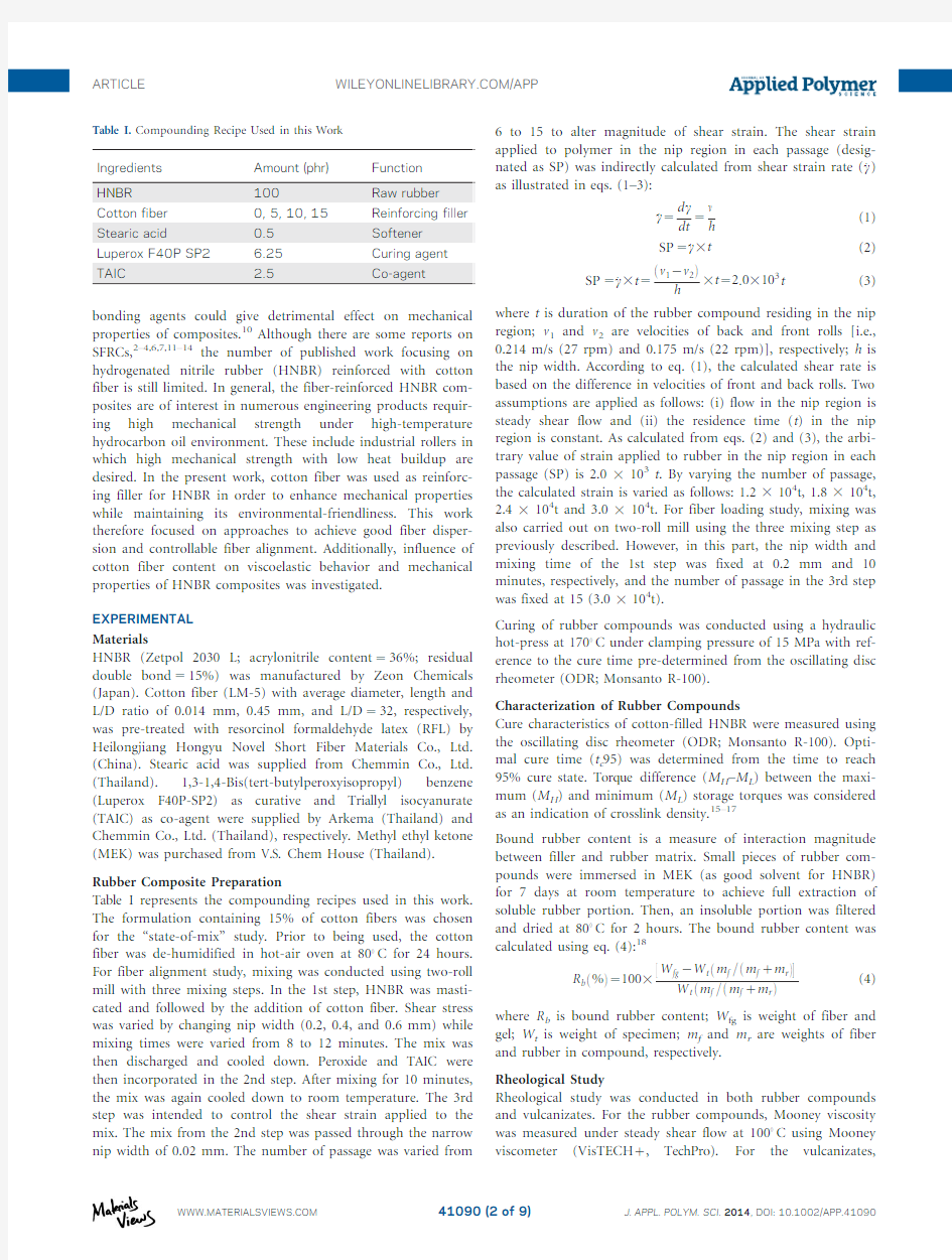
Table I represents the compounding recipes used in this work. The formulation containing15%of cotton fibers was chosen for the“state-of-mix”study.Prior to being used,the cotton fiber was de-humidified in hot-air oven at80 C for24hours. For fiber alignment study,mixing was conducted using two-roll mill with three mixing steps.In the1st step,HNBR was masti-cated and followed by the addition of cotton fiber.Shear stress was varied by changing nip width(0.2,0.4,and0.6mm)while mixing times were varied from8to12minutes.The mix was then discharged and cooled down.Peroxide and TAIC were then incorporated in the2nd step.After mixing for10minutes, the mix was again cooled down to room temperature.The3rd step was intended to control the shear strain applied to the mix.The mix from the2nd step was passed through the narrow nip width of0.02mm.The number of passage was varied from 6to15to alter magnitude of shear strain.The shear strain applied to polymer in the nip region in each passage(desig-nated as SP)was indirectly calculated from shear strain rate(_c) as illustrated in eqs.(1–3):
_c5
d c
dt
5
m
h
(1)
SP5_c3t(2) SP5_c3t5
v12v2
eT
3t52:03103t(3) where t is duration of the rubber compound residing in the nip region;v1and v2are velocities of back and front rolls[i.e., 0.214m/s(27rpm)and0.175m/s(22rpm)],respectively;h is the nip width.According to eq.(1),the calculated shear rate is based on the difference in velocities of front and back rolls.Two assumptions are applied as follows:(i)flow in the nip region is steady shear flow and(ii)the residence time(t)in the nip region is constant.As calculated from eqs.(2)and(3),the arbi-trary value of strain applied to rubber in the nip region in each passage(SP)is2.03103t.By varying the number of passage, the calculated strain is varied as follows:1.23104t,1.83104t, 2.43104t and3.03104t.For fiber loading study,mixing was also carried out on two-roll mill using the three mixing step as previously described.However,in this part,the nip width and mixing time of the1st step was fixed at0.2mm and10 minutes,respectively,and the number of passage in the3rd step was fixed at15(3.03104t).
Curing of rubber compounds was conducted using a hydraulic hot-press at170 C under clamping pressure of15MPa with ref-erence to the cure time pre-determined from the oscillating disc rheometer(ODR;Monsanto R-100).
Characterization of Rubber Compounds
Cure characteristics of cotton-filled HNBR were measured using the oscillating disc rheometer(ODR;Monsanto R-100).Opti-mal cure time(t c95)was determined from the time to reach 95%cure state.Torque difference(M H–M L)between the maxi-mum(M H)and minimum(M L)storage torques was considered as an indication of crosslink density.15–17
Bound rubber content is a measure of interaction magnitude between filler and rubber matrix.Small pieces of rubber com-pounds were immersed in MEK(as good solvent for HNBR) for7days at room temperature to achieve full extraction of soluble rubber portion.Then,an insoluble portion was filtered and dried at80 C for2hours.The bound rubber content was calculated using eq.(4):18
R be%T51003
?W fg2W tem f=em f1m rT
W tem f=em f1m rT
(4)
where R b is bound rubber content;W fg is weight of fiber and gel;W t is weight of specimen;m f and m r are weights of fiber and rubber in compound,respectively.
Rheological Study
Rheological study was conducted in both rubber compounds and vulcanizates.For the rubber compounds,Mooney viscosity was measured under steady shear flow at100 C using Mooney viscometer(VisTECH1,TechPro).For the vulcanizates,
Table https://www.doczj.com/doc/e813621041.html,pounding Recipe Used in this Work
Ingredients Amount(phr)Function
HNBR100Raw rubber Cotton fiber0,5,10,15Reinforcing filler Stearic acid0.5Softener Luperox F40P SP2 6.25Curing agent TAIC 2.5Co-agent
rheological behavior was studied under oscillatory flow using a Rubber Process Analyzer(RPA2000;Alpha Technologies).The compounds were first cured in RPA2000cavity at170 C and, then,the die temperature was decreased to100 C for perform-ing the strain sweep test(i.e.,strain range of0.5–100.02%)at a given angular frequency of2rad/s.Storage modulus(G0)of the vulcanizates was recorded,and the discrepancy in G0at strains of2and100%was taken as a magnitude of Payne effect(D G0). The lower magnitude of D G0suggests the lower degree of filler network,and thus the greater degree of filler dispersion.19,20In addition to RPA2000,a dynamic mechanical analyzer(Gabo, Explexor25N,Germany)was utilized to determine the visco-elastic properties of HNBR vulcanizates under tension mode with static and dynamic strain amplitudes of2and0.1%, respectively.Temperature sweep test was performed from280 to70 C with a scanning rate of2 C/min and a test frequency of10Hz.
Morphological Observation
Fiber dispersion and alignment were characterized qualitatively by the use of light microscope(VZM-1510;Itokin Technology Co.,Japan).Surfaces of cured sheets with thickness of approxi-mately1mm were cleaned to remove dusts before viewing. Apart from light microscope,a scanning electron microscope (JSM6400;JEOL Ltd.,Japan)was utilized to study the mechani-cal failure behavior.Fractured surfaces of rubber specimens from the tensile test were sputtered with gold before observation.
Mechanical Properties
Tensile properties were measured according to ASTM D412 while tear strength was measured as per ASTM D624.To inves-tigate the effect of fiber alignment,the tests were performed in both longitudinal(L)and transverse(T)directions using a uni-versal mechanical tester(Instron5569)at a crosshead speed of 500mm/min with a load cell of1kN.Hardness was determined on the cured specimens with thickness of at least6mm by the use of Shore A durometer(Wallace H17A,UK)at room tem-perature according to ASTM D2240-97.
Crosslink Density
In addition to the torque difference(M H–M L),crosslink density as defined by a number of active network chains per volume unit was determined by a swelling test via Flory-Rehner equa-tion as illustrated in eq.(5).The specimens were weighed and then immersed in an excess of MEK at room temperature.After 7days of swelling,the swollen specimens were weighed,and the elastically active network chains density(V e)or crosslink density was calculated:
V e52lne12V rT1V r1v V r2
V seV r2V r=2T
(5)
V r5
m0/12a
q r
m0/12a
q r
1m12m2
q s
(6)
where V r is the volume fraction of rubber in the swollen vulcan-izate calculated from eq.(6);m0is the specimen mass before swelling;m1and m2are specimen masses before and after dry-ing,respectively;?is the mass fraction of rubber in the composites;a is the mass loss of the gum HNBR vulcanizate during the swelling process;q r and q s are densities of rubber and solvent,respectively;v is the polymer–solvent interaction parameter(0.453for HNBR-MEK)and V s is the solvent molar volume(90.2cm3/mol for MEK)21,22
RESULTS AND DISCUSSION
Effect of State-of-Mix
Figure1reveals optical micrographs of fiber-filled HNBR vul-canizates prepared with various magnitude of shear stress
via Figure1.Micrographs(13x)of fiber-filled HNBR vulcanizates prepared with various nip widths:(a)0.2mm;(b)0.4mm;and(c)0.6mm.[Color figure can be viewed in the online issue,which is available at https://www.doczj.com/doc/e813621041.html,.]
nip width adjustment.At large nip widths (0.4and 0.6mm),large agglomerates of cotton fibers are observed indicating poor degree of fiber dispersion.However,by decreasing the nip width to 0.2mm,agglomerate size is reduced significantly,suggesting the drastic improvement in degree of fiber dispersion.Such improvement is explained by the increased shear stress and/or strain applied to the rubber,as illustrated in eq.(1).
Figure 2demonstrates optical micrographs of vulcanizates mixed with various mixing times.Evidently,an increase in mix-ing time from 8to 10minutes leads to obvious enhancement in
fiber dispersion.Such improvement in state-of-mix is due to the increase in magnitude of shear stress/strain applied to the rubber bulk.However,further increase in mixing time gives no significant change in degree of fiber dispersion.With prolonged mixing time,the shear heating caused by viscous dissipation gives rise to the increase in bulk temperature during the mixing process,which in turn reduces the shear stress applied to the rubber bulk.Simultaneously,when the filler size decreases,the critical stress required for breaking up the filler (also known as yield stress)increases.These lead to the unchanged state-of-mix as the mixing time is increased from 10to 12mins.
Figure 3exhibits the strain sweep test results of HNBR systems with different nip widths and mixing times.With decreasing nip width,shear storage modulus (G 0)at low strain reduces.This is also true for the increase in mixing time.Such high G 0at low strain is caused by a large amount of filler network con-taining immobilized rubber acting as parts of undeformable fil-ler.With increasing shear strain,the disruption of filler network causes a release of immobilized rubber to become mobilized rubber as evidenced by a decrease in G 0at high strain.Table II reports physical characteristics and mechanical properties of fiber-filled HNBR vulcanizates with different milling conditions.The difference in G 0at low and high strains (D G 0)or the so-called Payne effect is tabulated.From the results,D G 0
appears
Figure 2.Micrographs (13x)of fiber-filled HNBR vulcanizates prepared with various mixing times:(a)8mins.;(b)10mins.;and (c)12mins.[Color figure can be viewed in the online issue,which is available at
https://www.doczj.com/doc/e813621041.html,.]
Figure 3.Storage modulus (G 0)as a function of shear strain of fiber-filled HNBR vulcanizates prepared with different mixing parameters:(a)nip widths;(b)mixing times.[Color figure can be viewed in the online issue,which is available at https://www.doczj.com/doc/e813621041.html,.]
to decrease with decreasing nip width or increasing mixing time.This suggests the enhancement in filler dispersion sup-porting the morphological results as discussed previously.With increasing state-of-mix via reduced nip width and/or increased mixing time,the improvement in tensile properties is resulted.Tensile strength and elongation at break are increased due to a reduction in the number of fiber agglomerates acting as flaws in the rubber matrix.This is also true for the tear strength.Notice-ably,there is a strong anisotropic effect of cotton fiber on the vulcanizates as influenced by mixing conditions.In L direction,tensile strength,modulus and tear strength are greater whereas the elongation at break is lower,compared to those in T direction.
Regarding the degree of fiber alignment,Figure 4shows the micrographs of vulcanizates prepared with optimal nip width and mixing time (i.e.,0.2mm and 10mins.).The vulcanizates were prepared with different numbers of passage (i.e.,shear strains were varied from 1.23104t to 3.03104t.Evidently,good fiber dispersion in association with high magnitude of fiber alignment is observed when the rubber is subjected to high shear strain (3.03104t)during the mixing process.In other words,the increase in shear strain magnitude applied to rubber matrix is capable of enhancing the fiber alignment along the shear field direction.
In order to determine the magnitude of anisotropy,ratios of mechanical properties in L direction to those in T direction are calculated,and then plotted as a function of shear strain imposed to the rubber bulk (Figure 5).Obviously,fiber align-ment in L direction is more pronounced with increasing shear strain due to greater viscoelastic deformation of HNBR matrix.This leads to the increased reinforcement magnitude in the L direction,and thus the ratio of properties in L to T directions.Effect of Fiber Loading
Table III shows physical characteristics and mechanical proper-ties of HNBR compounds filled with various loadings of cotton fiber.With increasing cotton fiber loading,Mooney viscosity significantly increases which is attributed to the hydrodynamic effect in association with a formation of immobilized rubber in
fiber network and/or agglomerates.This suggests a decrease in processability with increased fiber loading.One might expect that such increase in viscosity is also due to the increase in rub-ber–filler interaction.As evidenced in the bound rubber results given in Table III,the bound rubber content is rather low even
Table II.Properties of Fiber-filled HNBR Composites in the Study of State-of-Mix
Fiber
Nip width (mm)
Mixing time (min)
Property
Orientation 0.20.40.68
1012Payne effect (D G 0)(kPa)–64365872068094161019406106630697619688Hardness (Shore A)–706171617162726272627262Tensile strength (MPa)L 5.160.5 4.760.3 4.660.2 4.760.2 5.260.1 5.260.2T 2.760.1 2.660.3 2.560.3 3.060.3 3.160.1 3.160.0Elongation at break (%)L 276420612065236231633467T 1896321416141376211336819363019961125%Modulus (M25)(MPa)L 4.960.1N/A
a
N/A
a
N/A
a
5.160.1 4.960.4T 1.760.2 1.360.2 1.660.2 1.060.1 2.060.2 1.360.1Tear strength (kN/m)
L 33.660.631.061.230.861.433.762.434.160.3
36.862.7T
27.861.4
21.160.4
20.261.1
30.861.8
60.3
35.262.2
a
M25could not be determined due to the elongation at break lower than
25%.
Figure 4.Micrographs (50x)of fiber-filled HNBR vulcanizates prepared with various shear strains:(a) 1.23104t;(b) 3.03104t.[Color figure can be viewed in the online issue,which is available at https://www.doczj.com/doc/e813621041.html,.]
at high fiber loading of 15phr.This finding is much different from that found in the systems filled with particulate reinforc-ing fillers including carbon black and precipitated silica.23,24In other words,the influence of rubber–polymer interaction on Mooney viscosity could be disregarded in this work.
Apart from Mooney viscosity,cure characteristics of HNBR compounds change significantly with increasing fiber loading.A decrease in optimum cure time is observed,which is in good accordance with a rise in crosslink density of HNBR vulcani-zates as determined from torque difference and swelling test via the Flory–Rehner equation as shown in Figure 6.The explana-tion of a cure promotion phenomenon found with increasing fiber loading is proposed in the aspect of thermal history during the mixing process.It is known that when filler loading increases,an increase in bulk viscosity leads to the increased shear heating and thus the accelerated rate of vulcanization.25Regarding the magnitude of filler–rubber interaction influenced by cotton fiber loading,the results (Table III)exhibit relatively low bound rubber content (BRC)compared to those of the car-bon black-filled nitrile rubber.23,24Anyway,there is still a trend of slight increase in BRC with fiber loading.The increase in
contact surface area due to the increase in fiber loading is believed to be responsible for such slight increase in BRC.Table III and Figure 7reveal hardness and modulus results in which the increases in both are observed with increasing fiber loading.Such increases are caused by a combined effect of hydrodynamic effect,rubber–filler interaction and filler–filler interaction.Similarity in result trends of hardness and modulus at low strain is not unusual because it is widely known that the measurement of hardness is analogous to the measurement of modulus at specimen surface.10,26Furthermore,at a given fiber loading,the modulus in L direction is greater than that in T direction.This is more pronounced in the case of low strain where a large amount of filler network exists.This finding is also applicable to tensile strength and elongation at break.It seems that the cotton fiber helps increasing load-bearing capa-bility of test specimens.The alignment of fiber in the L direc-tion (parallel to the applied load)could distribute the load more effectively than that in the T direction.On the other hand,the elongation at break decreases with increasing fiber loading particularly in the L direction.Referring to the modulus results illustrated previously in Figure 7,the modulus
increases
Figure 5.Anisotropic effects of fiber-filled HNBR vulcanizates as a func-tion of shear strain.
Table III.Physical Characteristics and Mechanical Properties of HNBR Compounds in the Study of Effect of Fiber Loading
Fiber
Fiber loading (phr)
Property
Orientation 0
5
1015Scorch time (t s 2)(min)
– 2.360.2 2.360.0 2.360.1 2.360.0Optimum cure time (t c 95)(min)–20.460.119.260.118.460.218.160.0Mooney viscosity (MU)–36.460.539.160.944.260.449.261.1Bound rubber (%)– 2.460.1 2.760.2 3.860.5 3.960.3Hardness (Shore A)–5061606166617261Tensile strength (MPa)L 2.760.4
2.760.1
3.460.5
4.760.3T – 2.160.1 2.360.1 2.560.1Elongation at break (%)L 2806772616516232068T –
179612169625158620Tear strength (kN/m)
L 11.760.620.662.524.861.533.061.2T
–17.861.0
23.161.2
26.46
0.8
Figure 6.Crosslink density of HNBR composites with various fiber loadings.
with increasing fiber loading,particularly in the L direction.Thus,the relatively high modulus and strength of fiber (com-pared with HNBR matrix)restricts the bulk deformation.Tear strength is found to increase with the increase in fiber loading,especially in the L direction.The results agree well with
the tensile strength and modulus.Such enhancement in tear strength by fiber addition is explained not only by load-bearing capability of fiber but also by the energy dissipation as a result of zig–zag route formation.27
Figure 8(a)demonstrates strain sweep test results of HNBR vul-canizates with various cotton fiber loadings.Evidently,the G 0at low strain significantly increases with increasing fiber loading.This suggests the increase in hydrodynamic effect in association with increased magnitude of filler network formation.19With increasing strain,the G 0of all systems decreases,and the great-est change in G 0is observed in the system with the highest fiber loading.Such reduction in G 0indicates the non-linearity of G 0as a result of filler network disruption.Since the filler network is caused by the H-bond between hydroxyl groups on cellulosic fiber surfaces,the network is transient and can be broken down at high strain.By considering the magnitude of Payne effect (D G 0)as shown in Figure 8(b),the D G 0increases progressively with fiber loading,supporting the explanation of filler network formation as discussed previously.
Figures.9and 10reveal the temperature sweep test results.Referring to Figure 9,a drastic change in tensile
storage
Figure 7.Modulus of HNBR composites with various fiber loadings.[Color figure can be viewed in the online issue,which is available at
https://www.doczj.com/doc/e813621041.html,.]
Figure 8.Strain sweep test results of HNBR composites with various fiber loadings:(a)storage modulus (G 0);(b)magnitude of Payne effects (D G 0).[Color figure can be viewed in the online issue,which is available at
https://www.doczj.com/doc/e813621041.html,.]
Figure 9.Effect of fiber loading on storage modulus (E 0)of HNBR com-posites with various fiber loadings.[Color figure can be viewed in the online issue,which is available at
https://www.doczj.com/doc/e813621041.html,.]
Figure 10.Effect of fiber loading on loss modulus (E”)of HNBR compo-sites with various fiber loadings.[Color figure can be viewed in the online issue,which is available at https://www.doczj.com/doc/e813621041.html,.]
modulus (E 0)caused by fiber loading is more pronounced in the rubbery region than the glassy region.This is because of the greater magnitude of molecular mobility.With increased fiber loading,rubber molecular mobility is more restricted by fiber,leading to the increase in E 0.This phenomenon is known as the hydrodynamic or dilution effect.In addition,the increase in crosslink density by increasing cotton fiber loading as demon-strated earlier in Figure 6is capable of reducing the molecular mobility to some extent.Notably,the E 0in L direction is much greater than that in T direction,agreeing well with the tensile modulus results discussed previously.
Figure 10shows a dependence of temperature on tensile loss modulus (E 00).Again,a significant change in E 00is noticeable in the rubbery region.With increasing fiber loading,the E 00increases implying increased energy loss (hysteresis loss)at fiber surfaces as a result of rubber molecular slippage on fiber surfa-ces.Such slippage is magnified by a poor interfacial adhesion between fiber and HNBR matrix as supported by the low BRC (see Table III).At a given fiber loading,the systems with fiber aligned in L direction exhibits greater E”,due to the higher contact area between fiber surfaces and rubber matrix in parallel direction to the applied stress.It must be noted that,within the experimental tolerance,there is no significant difference in glass transition temperature (T g ),regardless of fiber loading.This supports the relatively low interfacial adhesion between fiber and HNBR matrix as discussed previously.
According to SEM images in Figure 11,the addition of 5phr cotton fiber still gives good distribution of cotton fibers in HNBR matrix.Figure 11(b,d)exhibit fractured surfaces in the L direction in which the fibers with long L/D ratio could be observed.By contrast,the SEM images in Figure 11(c,e)show the fracture failure of composites via a pull-out mechanism
which is attributed to the poor interfacial adhesion of cotton fiber and HNBR.This finding is more pronounced at high fiber loading of 15phr as evidenced in Figure 11(d,e).
CONCLUSION
HNBR composites reinforced with cotton fiber were prepared.Degree of fiber alignment was controlled by mechanical shear stress/strain.Effects of fiber loading and alignment on mechani-cal properties,viscoelastic behavior,crosslink density and bound rubber content were investigated.Results reveal good dispersion and alignment of cotton fiber when the compounds are pre-pared at the nip width of 0.2mm,dispersion time of 10minutes and shear strain at arbitrary value 3.03104t.With increasing fiber loading,mechanical properties increase via the load-bearing capability of fiber in conjunction with the hystere-sis loss at fiber surfaces.A control of fiber to be in longitudinal direction to the applied stress is capable of enhancing the mechanical properties drastically particularly in the rubbery region.SEM images reveal poor interfacial adhesion between HNBR matrix and cotton fiber,which is in good agreement with the bound rubber content results.
ACKNOWLEDGMENTS
The authors would like to thank the Thailand Research Fund (TRF Research Senior Scholar;RTA 5580009)for financial support throughout this work.
REFERENCES
1.Vigo,L.T.;Kinzig,https://www.doczj.com/doc/e813621041.html,posite Applications The Role of Matrix,Fiber,and Interface;VCH Publishers:New York,1992
.
Figure 11.SEM images of HNBR composites with various loadings of cotton fiber:(a)unfilled;(b)5phr cotton fiber (L direction);(c)5phr cotton fiber (T direction);(d)15phr cotton fiber (L direction);and (e)15phr cotton fiber (T direction).
2.Kashani,M.R.J.Appl.Polym.Sci.2009,113,1355.
3.Tian,M.;Cheng,L.;Liang,W.;Zhang,L.Macromol.Mater.
Eng.2005,290,681.
4.Setua,D.K.;De,S.K.J.Mater.Sci.1984,19,983.
5.Lopattananon,N.;Jitkalong,D.;Seadan,M.J.Appl.Polym.
Sci.2011,120,3242.
6.Ryu,S.R.;Lee,D.J.KSME.Int.J.2001,15,35.
7.Tian,M.;Su,L.;Cai,W.;Yin,S.;Chen,Q.;Fong,H.;
Zhang,L.J.Appl.Polym.Sci.2011,120,1439.
8.Praveen,S.;Chattopadhyay,P.K.;Jayendran,S.;Chakraborty,
B.C.;Chattopadhyay,S.Polym.Int.2010,59,187.
9.Mwaikambo,L.Y.;Ansell,M.P.J.Appl.Polym.Sci.2002,
84,2222.
10.Dick,J.S.Rubber Technology Compounding and Testing
for Performance;Hanser Publishers:Munich,2001.
11.Zeng,Z.;Ren,W.;Xu,C.;Lu,W.;Zhang,Y.;Zhang,Y.J.
Appl.Polym.Sci.2009,111,437.
12.Elappunkal,T.J.;Mathew,R.;Thomas,P.C.;Thomas,S.;
Joseph,K.J.Appl.Polym.Sci.2009,114,2624.
13.L o pez-Manchado,M.A;Arroyo,https://www.doczj.com/doc/e813621041.html,posite2002,
23,666.
14.Rajeev,R.S.;Bhowmick,A.K.;De,S.K.;Bandyopadhyay,
S.J.Appl.Polym.Sci.2003,90,544.15.El-Sabbagh,S.H.;Yehia,A.A.Egypt.J.Solids2007,30,157.
16.Ismail,H.;Tan,S.;Poh,B.T.J.Elastom.Plast.2001,33,
251.
17.Arroyo,M.;L o pez-Manchado,M.A.;Herrero,B.Polymer
2003,44,2447.
18.Choi,S.S.Polym.Test.2002,21,201.
19.Fr€o hlich,J.;Niedermeier,W.;Luginsland,H. https://www.doczj.com/doc/e813621041.html,pos.
Part.A-Appl.S.2005,36,449.
20.Ye,X.;Tian M,Zhang,L.Q.J.Appl.Polym.Sci.2012,124,
927.
21.Guo,B.C.;Chen,F.;Chen,W.W.;Lei,Y.D.;Jia,D.M.
Express.Polym.Lett.2010,4,529.
22.Smitthipong,W.;Nardin,M.;Schultz,J.;Suchiva,K.Int.J.
Adhes.Adhes.2007,27,352.
23.Leblanc,J.L.J.Appl.Polym.Sci.2000,78,1541.
24.Bandyopadhyay,S.;De,P.P.;Tripathy,D.K.;De,S.K.Poly-
mer1996,37,353.
25.Rattanasom,N.;Saowapark,T.;Deeprasertkul, C.Polym.
Test.2007,26,369.
26.Hofmann,W.Rubber Technology Handbook Germany;
Hanser Publishers:Munich,1989.
27.Gatos,K.G.;Sawanis,N.S.;Apostolov,A.A.;Thomann,R.;
Karger-Kocsis,J.Macromol.Mater.Eng.2004,289,1079.