Damping-characteristics-of-unreinforced,-glass-and-carbon-fiber-reinforced-nylon-6-6-spur-gears_2006
- 格式:pdf
- 大小:351.85 KB
- 文档页数:7
3.2Definitions of Terms Specific to This Standard:3.2.1balanced laminate ,n —a continuous fiber-reinforcedlaminate in which each +u lamina,measured with respect to thelaminate reference axis,is balanced by a –u lamina of the samematerial (for example,[0/+45/–45/+45/–45/0]).3.2.2short-beam strength ,n —the shear stress as calculatedin Eq 1,developed at the specimen mid-plane at the failureevent specified in 11.6.3.2.2.1Discussion —Although shear is the dominant appliedloading in this test method,the internal stresses are complexand a variety of failure modes can occur.Elasticity solutions byBerg et al (1)7,Whitney (2),and Sullivan and Van Oene (3)have all demonstrated inadequacies in classical beam theory indefining the stress state in the short-beam configuration.Thesesolutions show that the parabolic shear-stress distribution aspredicted by Eq 1only occurs,and then not exactly,on planesmidway between the loading nose and support points.Awayfrom these planes,the stress distributions become skewed,withpeak stresses occurring near the loading nose and supportpoints.Of particular significance is the stress state local to theloading nose in which the severe shear-stress concentrationcombined with transverse and in-plane compressive stresseshas been shown to initiate failure.However,for the moreductile matrices,plastic yielding may alleviate the situationunder the loading nose (1)and allow other failure modes tooccur such as bottom surface fiber tension (2).Consequently,unless mid-plane interlaminar failure has been clearly ob-served,the short-beam strength determined from this testmethod cannot be attributed to a shear property,and the use ofEq 1will not yield an accurate value for shear strength.3.2.3symmetric laminate ,n —a continuous fiber-reinforcedlaminate in which each ply above the mid-plane is identicallymatched (in terms of position,orientation,and mechanicalproperties)with one below the mid-plane.3.3Symbols :b —specimen width.CV —sample coefficient of variation (in percent).F sbs —short-beam strength.h —specimen thickness.n —number of specimens.P m —maximum load observed during the test.x i —measured or derived property for an individual specimenfrom the sample population.x ¯—sample mean (average).4.Summary of Test Method4.1The short-beam test specimens (Figs.1-4)are center-loaded as shown in Figs.5and 6.The specimen ends rest ontwo supports that allow lateral motion,the load being appliedby means of a loading nose directly centered on the midpointof the test specimen.5.Significance and Use5.1In most cases,because of the complexity of internalstresses and the variety of failure modes that can occur in thisspecimen,it is not generally possible to relate the short-beam strength to any one material property.However,failures are normally dominated by resin and interlaminar properties,and the test results have been found to be repeatable for a given specimen geometry,material system,and stacking sequence (4).5.2Short-beam strength determined by this test method can be used for quality control and process specification purposes.It can also be used for comparative testing of composite materials,provided that failures occur consistently in the same mode (5).5.3This test method is not limited to specimens within the range specified in Section 8,but is limited to the use of a loading span length-to-specimen thickness ratio of 4.0and a minimum specimen thickness of 2.0mm [0.08in.].6.Interferences 6.1Accurate reporting of observed failure modes is essen-tial for meaningful data interpretation,in particular,the detec-tion of initial damage modes.7.Apparatus 7.1Testing Machine ,properly calibrated,which can be operated at a constant rate of crosshead motion,and which the error in the loading system shall not exceed 61%.The load-indicating mechanism shall be essentially free of inertia7Boldface numbers in parentheses refer to the list of references at the end of thisstandard.N OTE 1—Drawing interpretation per ANSI Y14.5-1982and ANSI/ASM B46.1-1986.N OTE 2—Ply orientation tolerance 60.5°relative to –B–.FIG.1Flat Specimen Configuration(SI)lag at the crosshead rate used.Inertia lag may not exceed 1%of the measured load.The accuracy of the testing machine shallbe verified in accordance with Practices E 4.7.2Loading Nose and Supports ,as shown in Figs.5and 6,shall be 6.00-mm (0.250-in.)and 3.00-mm (0.125-in.)diametercylinders,respectively,with a hardness of 60to 62HRC,asspecified in Test Methods E 18,and shall have finely groundsurfaces free of indentation and burrs with all sharp edgesrelieved.7.3Micrometers —For width and thickness measurements,the micrometers shall use a 4-to 5-mm (0.16-to 0.2-in.)nominal diameter ball interface on an irregular surface such asthe bag side of a laminate and a flat anvil interface on machinededges or very smooth tooled surfaces.A micrometer or caliperwith flat anvil faces shall be used to measure the length of thespecimen.The accuracy of the instrument(s)shall be suitablefor reading to within 1%of the sample dimensions.For typicalsection geometries,an instrument with an accuracy of 60.002mm (60.0001in.)is desirable for thickness and width mea-surement,while an instrument with an accuracy of 60.1mm(60.004in.)is adequate for length measurement.7.4Conditioning Chamber ,when conditioning materials atnonlaboratory environments,a temperature/vapor-level-controlled environmental conditioning chamber is required thatshall be capable of maintaining the required temperature towithin 63°C (65°F)and the required vapor level to within63%.Chamber conditions shall be monitored either on an automated continuous basis or on a manual basis at regular intervals.7.5Environmental Test Chamber ,an environmental test chamber is required for test environments other than ambient testing laboratory conditions.This chamber shall be capable of maintaining the test specimen at the required test environment during the mechanical test method.8.Sampling and Test Specimens 8.1Sampling —Test at least five specimens per test condi-tion unless valid results can be gained through the use of fewer specimens,as in the case of a designed experiment.For statistically significant data,consult the procedures outlined in Practice E 122.Report the method of sampling.8.2Geometry :8.2.1Laminate Configurations —Both multidirectional and pure unidirectional laminates can be tested,provided that there are at least 10%0°fibers in the span direction of the beam (preferably well distributed through the thickness),and that the laminates are both balanced and symmetric with respect to the span direction of the beam.8.2.2Specimen Configurations —Typical configurations for the flat and curved specimens are shown in Figs.1-4.For specimen thicknesses other than those shown,the following geometries are recommended:Specimen length =thickness 36Specimen width,b =thickness 32.0N OTE 2—Analysis reported by Lewis and Adams (6)has shown that a width-to-thickness ratio of greater than 2.0can result in a significant width-wise shear-stress variation.8.2.2.1For curved beam specimens,it is recommended that the arc should not exceed 30°.Also,for these specimens,the specimen length is defined as the minimum chord length.8.3Specimen Preparation —Guide D 5687/D 5687M pro-vides recommended specimen preparation practices and should be followed where practical.8.3.1Laminate Fabrication —Laminates may be hand-laid,filament-wound or tow-placed,and molded by any suitable laminating means,such as press,bag,autoclave,or resin transfer molding.8.3.2Machining Methods —Specimen preparation is impor-tant for these specimens.Take precautions when cutting specimens from the rings or plates to avoid notches,undercuts,rough or uneven surfaces,or delaminations as a result of inappropriate machining methods.Obtain final dimensions by water-lubricated precision sawing,milling,or grinding.The use of diamond tooling has been found to be extremely effective for many material systems.Edges should be flat and parallel within the specified tolerances.8.3.3Labeling —Label the specimens so that they will be distinct from each other and traceable back to the raw material,in a manner that will both be unaffected by the test method and not influence the test method.9.Calibration 9.1The accuracy of all measuring equipment shall have certified calibrations that are current at the time of use of theequipment.N OTE 1—Drawing interpretation per ANSI Y14.5-1982and ANSI/ASME B46.1-1986.N OTE 2—Ply orientation tolerance 60.5°relative to –B–.FIG.2Flat Specimen Configuration (InchPound)10.Conditioning10.1Standard Conditioning Procedure —Unless a differentenvironment is specified as part of the test method,conditionthe test specimens in accordance with Procedure C of TestMethod D 5229/D 5229M,and store and test at standardlaboratory atmosphere (2363°C (7365°F)and 50610%relative humidity).11.Procedure11.1Parameters to Be Specified Before Test :11.1.1The specimen sampling method and coupon geom-etry.11.1.2The material properties and data-reporting formatdesired.N OTE 3—Determine specific material property,accuracy,and data-reporting requirements before test for proper selection of instrumentation and data-recording equipment.Estimate operating stress levels to aid in calibration of equipment and determination of equipment settings.11.1.3The environmental conditioning test parameters.11.1.4If performed,the sampling test method,coupon geometry,and test parameters used to determine density and reinforcement volume.11.2General Instructions :11.2.1Report any deviations from this test method,whether intentional or inadvertent.11.2.2If specific gravity,density,reinforcement volume,or void volume are to be reported,then obtain these samples from the same panels as the test samples.Specific gravityandN OTE 1—Drawing interpretation per ANSI Y14.5-1982and ANSI/ASM B46.1-1986.N OTE 2—Ply orientation tolerance 60.5°relative to –A–.FIG.3Curved Specimen Configuration(SI)density may be evaluated by means of Test Methods D 792.V olume percent of the constituents may be evaluated by one ofthe matrix digestion procedures of Test Method D 3171,or forcertain reinforcement materials such as glass and ceramics,bythe matrix burn-off technique of Test Method D 2584.V oidcontent may be evaluated from the equations of Test MethodD 2734and are applicable to both Test Methods D 2584andD 3171.11.2.3Condition the specimens as required.Store the speci-mens in the conditioned environment until test time,if the testenvironment is different from the conditioning environment.11.2.4Following final specimen machining and any condi-tioning,but before testing,measure and record the specimenwidth and thickness at the specimen midsection and thespecimen length to the accuracy specified in 7.3.11.3Speed of Testing —Set the speed of testing at a rate of crosshead movement of 1.0mm (0.05in.)/min.11.4Test Environment —If possible,test the specimen under the same fluid exposure level as that used for conditioning.However,if the test temperature places too severe requirements upon the testing machine environmental chamber,test at a temperature with no fluid exposure control.In this case,a restriction must be placed upon the time from removal of the specimen from the conditioning chamber until test completion to inhibit nonrepresentative fluid loss from the specimen.Record any modifications to the test environment and specimen weight change after removal from conditioning until test completion.11.4.1Monitor the test temperature by placing an appropri-ate thermocouple at specimen mid-length to be located ontheN OTE 1—Drawing interpretation per ANSI Y14.5-1982and ANSI/ASME B46.1-1986.N OTE 2—Ply orientation tolerance 60.5°relative to –A–.FIG.4Curved Specimen Configuration (InchPound)underside of the beam.11.5Specimen Insertion —Insert the specimen into the testfixture,with the toolside resting on the reaction supports asshown in Fig.5or Fig.6.Align and center the specimen suchthat its longitudinal axis is perpendicular to the loading noseand side supports.Adjust the span such that the span-to-measured thickness ratio is 4.0to an accuracy of 60.3mm(0.012in.).The loading nose should be located equidistantbetween the side supports to within 60.3mm (0.012in.).Boththe loading nose and side supports should overhang thespecimen width by at least 2mm (0.08in.)at each side.In thecase of the flat laminate test,each specimen end shouldoverhang the side support centers by at least the specimenthickness.11.6Loading —Apply load to the specimen at the specifiedrate while recording data.Continue loading until either of thefollowing occurs:11.6.1A load drop-off of 30%,11.6.2Two-piece specimen failure,or11.6.3The head travel exceeds the specimen nominal thick-ness.11.7Data Recording —Record load versus crosshead dis-placement data throughout the test method.Record the maxi-mum load,final load,and the load at any obvious discontinui-ties in the load-displacement data.11.8Failure Mode —Typical failure modes that can be identified visually are shown in Fig.7.However,these may be preceded by less obvious,local damage modes such as transply cracking.Record the mode and location of failure,if possible identifying one or a combination of the modes shown.12.Calculation 12.1Short-Beam Strength —Calculate the short-beam strength using Eq 1as follows:F sbs 50.753P m b 3h (1)where:F sbs =short-beam strength,MPa (psi);P m =maximum load observed during the test,N (lbf);b =measured specimen width,mm (in.),and h =measured specimen thickness,mm (in.).12.2Statistics —For each series of test methods,calculate the average value,standard deviation,and coefficient of varia-tion (in percent)for each property determined asfollows:FIG.5Horizontal Shear Load Diagram (CurvedBeam)FIG.6Horizontal Shear Load Diagram (FlatLaminate)x 5~(i –1n x i !/n (2)s n –15Œ~(i 51nx i 2–n ~x !2!/~n –1!(3)CV 51003s n –1/x(4)where:x ¯=sample mean (average);s n–1=sample standard deviation;CV =sample coefficient of variation,%;n =number of specimens;and x i =measured or derived property.13.Report13.1Report the following information,or references point-ing to other documentation containing this information,to themaximum extent applicable (reporting of items beyond thecontrol of a given testing laboratory,such as might occur withmaterial details or panel fabrication parameters,shall be theresponsibility of the requester):N OTE 4—Guides E 1309,E 1434,and E 1471contain data reportingrecommendations for composite materials and composite materials me-chanical testing.13.1.1This test method and revision level or date of issue.13.1.2Whether the coupon configuration was standard orvariant.13.1.3The date and location of the test.13.1.4The name of the test operator.13.1.5Any variations to this test method,anomalies noticedduring testing,or equipment problems occurring during testing.13.1.6Identification of the material tested including:mate-rial specification,material type,material designation,manufac-turer,manufacturer’s batch or lot number,source (if not from manufacturer),date of certification,expiration of certification,filament diameter,tow or yarn filament count and twist,sizing,form or weave,fiber areal weight,matrix type,prepreg matrix content,and prepreg volatiles content.13.1.7Description of the fabrication steps used to prepare the laminate including:fabrication start date,fabrication end date,process specification,cure cycle,consolidation method,and a description of the equipment used.13.1.8Ply orientation and stacking sequence of the lami-nate.13.1.9If requested,report density,volume percent rein-forcement,and void content test methods,specimen sampling method and geometries,test parameters,and test results.13.1.10Average ply thickness of the material.13.1.11Results of any nondestructive evaluation tests.13.1.12Method of preparing the test specimen,including specimen labeling scheme and method,specimen geometry,sampling method,and coupon cutting method.13.1.13Calibration dates and methods for all measurements and test equipment.13.1.14Details of loading nose and side supports including diameters and material used.13.1.15Type of test machine,alignment results,and data acquisition sampling rate and equipment type.13.1.16Dimensions of each test specimen.13.1.17Conditioning parameters and results.13.1.18Relative humidity and temperature of the testing laboratory.13.1.19Environment of the test machine environmental chamber (if used)and soak time at environment.13.1.20Number of specimens tested.13.1.21Speed oftesting.FIG.7Typical Failure Modes in the Short BeamTest13.1.22Maximum load observed during the test,for eachspecimen.13.1.23Load-displacement curves for each specimen.13.1.24Failure mode of each specimen,identified if pos-sible from Fig.7.14.Precision and Bias14.1Precision —The data required for the development of aprecision statement is not currently available for this testmethod.14.2Bias —Bias cannot be determined for this test method as no acceptable reference standard exists.15.Keywords 15.1composite materials;resin and interlaminar properties;short-beam strengthREFERENCES(1)Berg,C.A.,Tirosh,J.,and Israeli,M.,“Analysis of Short BeamBending of Fiber Reinforced Composites,”in Composite Materials:Testing and Design (Second Conference),ASTM STP 497,ASTM,1972,pp.206-218.(2)Whitney,J.M.,and Browning,C.E.,“On Short-Beam Shear Tests forComposite Materials,”Experimental Mechanics ,V ol 25,1985,pp.294-300.(3)Sullivan,J.L.,and Van Oene,H.,“An Elasticity Analysis for theGenerally and Specially Orthotropic Beams Subjected to ConcentratedLoads,”Composites Science and Technology ,V ol 27,1986,pp.182-191.(4)U.S.Department of Transportation,Federal Aviation Administration,“Test Methods for Composites a Status Report:V olume III Shear Test Methods,”Report No.DOT/FAA/CT-93/17,III,FAA Technical Cen-ter,Atlantic City,1993.(5)Cui,W.,Wisnom,M.R.,and Jones,M.,“Effect of Specimen Size on Interlaminar Shear Strength of Unidirectional Carbon Fibre-Epoxy,”Composites Engineering ,V ol 4,No.3,1994,pp.299-307.(6)Adams,D.F.and Lewis,E.Q.,“Current Status of Composite Material Shear Test Methods,”SAMPE ,V ol 31,No.6,1994,pp.32-41.The American Society for Testing and Materials takes no position respecting the validity of any patent rights asserted in connection with any item mentioned in this ers of this standard are expressly advised that determination of the validity of any such patent rights,and the risk of infringement of such rights,are entirely their own responsibility.This standard is subject to revision at any time by the responsible technical committee and must be reviewed every five years and if not revised,either reapproved or withdrawn.Your comments are invited either for revision of this standard or for additional standards and should be addressed to ASTM Headquarters.Your comments will receive careful consideration at a meeting of the responsible technical committee,which you may attend.If you feel that your comments have not received a fair hearing you should make your views known to the ASTM Committee on Standards,at the address shown below.This standard is copyrighted by ASTM,100Barr Harbor Drive,PO Box C700,West Conshohocken,PA 19428-2959,United States.Individual reprints (single or multiple copies)of this standard may be obtained by contacting ASTM at the above address or at 610-832-9585(phone),610-832-9555(fax),or service@ (e-mail);or through the ASTM website().。
Designation:D790–07Standard Test Methods forFlexural Properties of Unreinforced and Reinforced Plastics and Electrical Insulating Materials1This standard is issued under thefixed designation D790;the number immediately following the designation indicates the year of original adoption or,in the case of revision,the year of last revision.A number in parentheses indicates the year of last reapproval.A superscript epsilon(e)indicates an editorial change since the last revision or reapproval.This standard has been approved for use by agencies of the Department of Defense.1.Scope*1.1These test methods cover the determination offlexural properties of unreinforced and reinforced plastics,including high-modulus composites and electrical insulating materials in the form of rectangular bars molded directly or cut from sheets, plates,or molded shapes.These test methods are generally applicable to both rigid and semirigid materials.However,flexural strength cannot be determined for those materials that do not break or that do not fail in the outer surface of the test specimen within the5.0%strain limit of these test methods. These test methods utilize a three-point loading system applied to a simply supported beam.A four-point loading system method can be found in Test Method D6272.1.1.1Procedure A,designed principally for materials that break at comparatively small deflections.1.1.2Procedure B,designed particularly for those materials that undergo large deflections during testing.1.1.3Procedure A shall be used for measurement offlexural properties,particularlyflexural modulus,unless the material specification states otherwise.Procedure B may be used for measurement offlexural strength only.Tangent modulus data obtained by Procedure A tends to exhibit lower standard deviations than comparable data obtained by means of Proce-dure B.1.2Comparative tests may be run in accordance with either procedure,provided that the procedure is found satisfactory for the material being tested.1.3The values stated in SI units are to be regarded as the standard.The values provided in brackets are for information only.1.4This standard does not purport to address all of the safety concerns,if any,associated with its use.It is the responsibility of the user of this standard to establish appro-priate safety and health practices and determine the applica-bility of regulatory limitations prior to use.N OTE1—These test methods are not technically equivalent to ISO178.2.Referenced Documents2.1ASTM Standards:2D618Practice for Conditioning Plastics for TestingD638Test Method for Tensile Properties of PlasticsD883Terminology Relating to PlasticsD4000Classification System for Specifying Plastic Mate-rialsD4101Specification for Polypropylene Injection and Ex-trusion MaterialsD5947Test Methods for Physical Dimensions of Solid Plastics SpecimensD6272Test Method for Flexural Properties of Unrein-forced and Reinforced Plastics and Electrical Insulating Materials by Four-Point BendingE4Practices for Force Verification of Testing Machines E691Practice for Conducting an Interlaboratory Study to Determine the Precision of a Test Method2.2ISO Standard:3ISO178Plastics—Determination of Flexural Properties of Rigid Plastics3.Terminology3.1Definitions—Definitions of terms applying to these test methods appear in Terminology D883and Annex A1of Test Method D638.4.Summary of Test Method4.1A bar of rectangular cross section rests on two supports and is loaded by means of a loading nose midway between the supports.A support span-to-depth ratio of16:1shall be used unless there is reason to suspect that a larger span-to-depth ratio may be required,as may be the case for certain laminated materials(see Section7and Note7for guidance).1These test methods are under the jurisdiction of ASTM Committee D20on Plastics and are the direct responsibility of Subcommittee D20.10on Mechanical Properties.Current edition approved Sept.1,2007.Published October2007.Originally approved st previous edition approved in2003as D790–03.2For referenced ASTM standards,visit the ASTM website,,or contact ASTM Customer Service at service@.For Annual Book of ASTM Standards volume information,refer to the standard’s Document Summary page on the ASTM website.3Available from American National Standards Institute(ANSI),25W.43rd St., 4th Floor,New York,NY10036,.*A Summary of Changes section appears at the end of this standard. Copyright©ASTM International,100Barr Harbor Drive,PO Box C700,West Conshohocken,PA19428-2959,United States.4.2The specimen is deflected until rupture occurs in the outer surface of the test specimen or until a maximum strain (see 12.7)of5.0%is reached,whichever occurs first.4.3Procedure A employs a strain rate of 0.01mm/mm/min [0.01in./in./min]and is the preferred procedure for this test method,while Procedure B employs a strain rate of 0.10mm/mm/min [0.10in./in./min].5.Significance and Use5.1Flexural properties as determined by these test methods are especially useful for quality control and specification purposes.5.2Materials that do not fail by the maximum strain allowed under these test methods (3-point bend)may be more suited to a 4-point bend test.The basic difference between the two test methods is in the location of the maximum bending moment and maximum axial fiber stresses.The maximum axial fiber stresses occur on a line under the loading nose in 3-point bending and over the area between the loading noses in 4-point bending.5.3Flexural properties may vary with specimen depth,temperature,atmospheric conditions,and the difference in rate of straining as specified in Procedures A and B (see also Note 7).5.4Before proceeding with these test methods,reference should be made to the ASTM specification of the material being tested.Any test specimen preparation,conditioning,dimensions,or testing parameters,or combination thereof,covered in the ASTM material specification shall take prece-dence over those mentioned in these test methods.Table 1in Classification System D 4000lists the ASTM material speci-fications that currently exist for plastics.6.Apparatus6.1Testing Machine —A properly calibrated testing ma-chine that can be operated at constant rates of crosshead motion over the range indicated,and in which the error in the load measuring system shall not exceed 61%of the maximum load expected to be measured.It shall be equipped with a deflection measuring device.The stiffness of the testing machine shall be such that the total elastic deformation of the system does not exceed 1%of the total deflection of the test specimen duringtesting,or appropriate corrections shall be made.The load indicating mechanism shall be essentially free from inertial lag at the crosshead rate used.The accuracy of the testing machine shall be verified in accordance with Practices E 4.6.2Loading Noses and Supports —The loading nose and supports shall have cylindrical surfaces.The default radii of the loading nose and supports shall be 5.060.1mm [0.19760.004in.]unless otherwise specified in an ASTM material specification or as agreed upon between the interested parties.When the use of an ASTM material specification,or an agreed upon modification,results in a change to the radii of the loading nose and supports,the results shall be clearly identified as being obtained from a modified version of this test method and shall include the specification (when available)from which the modification was specified,for example,Test Method D 790in accordance with Specification D 4101.6.2.1Other Radii for Loading Noses and Supports —When other than default loading noses and supports are used,in order to avoid excessive indentation,or failure due to stress concen-tration directly under the loading nose,they must comply with the following requirements:they shall have a minimum radius of 3.2mm [1⁄8in.]for all specimens.For specimens 3.2mm or greater in depth,the radius of the supports may be up to 1.6times the specimen depth.They shall be this large if significant indentation or compressive failure occurs.The arc of the loading nose in contact with the specimen shall be sufficiently large to prevent contact of the specimen with the sides of the nose.The maximum radius of the loading nose shall be no more than four times the specimen depth.6.3Micrometers —Suitable micrometers for measuring the width and thickness of the test specimen to an incremental discrimination of at least 0.025mm [0.001in.]should be used.All width and thickness measurements of rigid and semirigid plastics may be measured with a hand micrometer with ratchet.A suitable instrument for measuring the thickness of nonrigid test specimens shall have:a contact measuring pressure of 2562.5kPa [3.660.36psi],a movable circular contact foot 6.3560.025mm [0.25060.001in.]in diameter and a lower fixed anvil large enough to extend beyond the contact foot in all directions and being parallel to the contact foot within 0.005mm [0.002in.]over the entire foot area.Flatness of foot and anvil shall conform to the portion of the Calibration section of Test Methods D 5947.7.Test Specimens7.1The specimens may be cut from sheets,plates,or molded shapes,or may be molded to the desired finished dimensions.The actual dimensions used in Section 4.2,Cal-culation,shall be measured in accordance with Test Methods D 5947.N OTE 2—Any necessary polishing of specimens shall be done only in the lengthwise direction of the specimen.7.2Sheet Materials (Except Laminated Thermosetting Ma-terials and Certain Materials Used for Electrical Insulation,Including Vulcanized Fiber and Glass Bonded Mica):7.2.1Materials 1.6mm [1⁄16in.]or Greater in Thickness —For flatwise tests,the depth of the specimen shall be the thickness of the material.For edgewise tests,the width of theTABLE 1Flexural StrengthMaterial Mean,103psiValues Expressed in Units of %of 103psi V r A V R B r C R D ABS9.99 1.59 6.05 4.4417.2DAP thermoset 14.3 6.58 6.5818.618.6Cast acrylic 16.3 1.6711.3 4.7332.0GR polyester19.5 1.43 2.14 4.05 6.08GR polycarbonate 21.0 5.16 6.0514.617.1SMC26.04.767.1913.520.4AV r =within-laboratory coefficient of variation for the indicated material.It is obtained by first pooling the within-laboratory standard deviations of the test results from all of the participating laboratories:Sr =[[(s 1)2+(s 2)2...+(s n )2]/n]1/2then V r =(S r divided by the overall average for the material)3100.BV r =between-laboratory reproducibility,expressed as the coefficient of varia-tion:S R ={S r 2+S L 2}1/2where S L is the standard deviation of laboratory means.Then:V R =(S R divided by the overall average for the material)3100.Cr =within-laboratory critical interval between two test results =2.83V r .DR =between-laboratory critical interval between two test results =2.83V R.specimen shall be the thickness of the sheet,and the depth shall not exceed the width(see Notes3and4).For all tests,the support span shall be16(tolerance61)times the depth of the beam.Specimen width shall not exceed one fourth of the support span for specimens greater than3.2mm[1⁄8in.]in depth.Specimens3.2mm or less in depth shall be12.7mm[1⁄2 in.]in width.The specimen shall be long enough to allow for overhanging on each end of at least10%of the support span, but in no case less than6.4mm[1⁄4in.]on each end.Overhang shall be sufficient to prevent the specimen from slipping through the supports.N OTE3—Whenever possible,the original surface of the sheet shall be unaltered.However,where testing machine limitations make it impossible to follow the above criterion on the unaltered sheet,one or both surfaces shall be machined to provide the desired dimensions,and the location of the specimens with reference to the total depth shall be noted.The value obtained on specimens with machined surfaces may differ from those obtained on specimens with original surfaces.Consequently,any specifi-cations forflexural properties on thicker sheets must state whether the original surfaces are to be retained or not.When only one surface was machined,it must be stated whether the machined surface was on the tension or compression side of the beam.N OTE4—Edgewise tests are not applicable for sheets that are so thin that specimens meeting these requirements cannot be cut.If specimen depth exceeds the width,buckling may occur.7.2.2Materials Less than1.6mm[1⁄16in.]in Thickness—The specimen shall be50.8mm[2in.]long by12.7mm[1⁄2in.] wide,testedflatwise on a25.4-mm[1-in.]support span.N OTE5—Use of the formulas for simple beams cited in these test methods for calculating results presumes that beam width is small in comparison with the support span.Therefore,the formulas do not apply rigorously to these dimensions.N OTE6—Where machine sensitivity is such that specimens of these dimensions cannot be measured,wider specimens or shorter support spans,or both,may be used,provided the support span-to-depth ratio is at least14to1.All dimensions must be stated in the report(see also Note5).7.3Laminated Thermosetting Materials and Sheet and Plate Materials Used for Electrical Insulation,Including Vulcanized Fiber and Glass-Bonded Mica—For paper-base and fabric-base grades over25.4mm[1in.]in nominal thickness,the specimens shall be machined on both surfaces to a depth of25.4mm.For glass-base and nylon-base grades, specimens over12.7mm[1⁄2in.]in nominal depth shall be machined on both surfaces to a depth of12.7mm.The support span-to-depth ratio shall be chosen such that failures occur in the outerfibers of the specimens,due only to the bending moment(see Note7).Therefore,a ratio larger than16:1may be necessary(32:1or40:1are recommended).When laminated materials exhibit low compressive strength perpendicular to the laminations,they shall be loaded with a large radius loading nose(up to four times the specimen depth to prevent premature damage to the outerfibers.7.4Molding Materials(Thermoplastics and Thermosets)—The recommended specimen for molding materials is127by 12.7by3.2mm[5by1⁄2by1⁄8in.]testedflatwise on a support span,resulting in a support span-to-depth ratio of16(tolerance 61).Thicker specimens should be avoided if they exhibit significant shrink marks or bubbles when molded.7.5High-Strength Reinforced Composites,Including Highly Orthotropic Laminates—The span-to-depth ratio shall be cho-sen such that failure occurs in the outerfibers of the specimens and is due only to the bending moment(see Note7).A span-to-depth ratio larger than16:1may be necessary(32:1or 40:1are recommended).For some highly anisotropic compos-ites,shear deformation can significantly influence modulus measurements,even at span-to-depth ratios as high as40:1. Hence,for these materials,an increase in the span-to-depth ratio to60:1is recommended to eliminate shear effects when modulus data are required,it should also be noted that the flexural modulus of highly anisotropic laminates is a strong function of ply-stacking sequence and will not necessarily correlate with tensile modulus,which is not stacking-sequence dependent.N OTE7—As a general rule,support span-to-depth ratios of16:1are satisfactory when the ratio of the tensile strength to shear strength is less than8to1,but the support span-to-depth ratio must be increased for composite laminates having relatively low shear strength in the plane of the laminate and relatively high tensile strength parallel to the support span.8.Number of Test Specimens8.1Test at leastfive specimens for each sample in the case of isotropic materials or molded specimens.8.2For each sample of anisotropic material in sheet form, test at leastfive specimens for each of the following conditions. Recommended conditions areflatwise and edgewise tests on specimens cut in lengthwise and crosswise directions of the sheet.For the purposes of this test,“lengthwise”designates the principal axis of anisotropy and shall be interpreted to mean the direction of the sheet known to be stronger inflexure.“Cross-wise”indicates the sheet direction known to be the weaker in flexure and shall be at90°to the lengthwise direction.9.Conditioning9.1Conditioning—Condition the test specimens at236 2°C[73.463.6°F]and5065%relative humidity for not less than40h prior to test in accordance with Procedure A of Practice D618unless otherwise specified by contract or the relevant ASTM material specification.Reference pre-test con-ditioning,to settle disagreements,shall apply tolerances of 61°C[1.8°F]and62%relative humidity.9.2Test Conditions—Conduct the tests at2362°C[73.46 3.6°F]and5065%relative humidity unless otherwise specified by contract or the relevant ASTM material specifica-tion.Reference testing conditions,to settle disagreements, shall apply tolerances of61°C[1.8°F]and62%relative humidity.10.Procedure10.1Procedure A:10.1.1Use an untested specimen for each measurement. Measure the width and depth of the specimen to the nearest 0.03mm[0.001in.]at the center of the support span.For specimens less than2.54mm[0.100in.]in depth,measure the depth to the nearest0.003mm[0.0005in.].These measure-ments shall be made in accordance with Test Methods D5947.10.1.2Determine the support span to be used as described in Section7and set the support span to within1%of the determinedvalue.10.1.3Forflexuralfixtures that have continuously adjust-able spans,measure the span accurately to the nearest0.1mm [0.004in.]for spans less than63mm[2.5in.]and to the nearest 0.3mm[0.012in.]for spans greater than or equal to63mm [2.5in.].Use the actual measured span for all calculations.For flexuralfixtures that havefixed machined span positions,verify the span distance the same as for adjustable spans at each machined position.This distance becomes the span for that position and is used for calculations applicable to all subse-quent tests conducted at that position.See Annex A2for information on the determination of and setting of the span.10.1.4Calculate the rate of crosshead motion as follows and set the machine for the rate of crosshead motion as calculated by Eq1:R5ZL2/6d(1) where:R=rate of crosshead motion,mm[in.]/min,L=support span,mm[in.],d=depth of beam,mm[in.],andZ=rate of straining of the outerfiber,mm/mm/min[in./ in./min].Z shall be equal to0.01.In no case shall the actual crosshead rate differ from that calculated using Eq1,by more than610%.10.1.5Align the loading nose and supports so that the axes of the cylindrical surfaces are parallel and the loading nose is midway between the supports.The parallelism of the apparatus may be checked by means of a plate with parallel grooves into which the loading nose and supports willfit when properly aligned(see A2.3).Center the specimen on the supports,with the long axis of the specimen perpendicular to the loading nose and supports.10.1.6Apply the load to the specimen at the specified crosshead rate,and take simultaneous load-deflection data. Measure deflection either by a gage under the specimen in contact with it at the center of the support span,the gage being mounted stationary relative to the specimen supports,or by measurement of the motion of the loading nose relative to the supports.Load-deflection curves may be plotted to determine theflexural strength,chord or secant modulus or the tangent modulus of elasticity,and the total work as measured by the area under the load-deflection curve.Perform the necessary toe compensation(see Annex A1)to correct for seating and indentation of the specimen and deflections in the machine.10.1.7Terminate the test when the maximum strain in the outer surface of the test specimen has reached0.05mm/mm [in./in.]or at break if break occurs prior to reaching the maximum strain(Notes8and9).The deflection at which this strain will occur may be calculated by letting r equal0.05 mm/mm[in./in.]in Eq2:D5rL2/6d(2) where:D=midspan deflection,mm[in.],r=strain,mm/mm[in./in.],L=support span,mm[in.],andd=depth of beam,mm[in.].N OTE8—For some materials that do not yield or break within the5% strain limit when tested by Procedure A,the increased strain rate allowed by Procedure B(see10.2)may induce the specimen to yield or break,or both,within the required5%strain limit.N OTE9—Beyond5%strain,this test method is not applicable.Some other mechanical property might be more relevant to characterize mate-rials that neither yield nor break by either Procedure A or Procedure B within the5%strain limit(for example,Test Method D638may be considered).10.2Procedure B:10.2.1Use an untested specimen for each measurement.10.2.2Test conditions shall be identical to those described in10.1,except that the rate of straining of the outer surface of the test specimen shall be0.10mm/mm[in./in.]/min.10.2.3If no break has occurred in the specimen by the time the maximum strain in the outer surface of the test specimen has reached0.05mm/mm[in./in.],discontinue the test(see Note9).11.Retests11.1Values for properties at rupture shall not be calculated for any specimen that breaks at some obvious,fortuitousflaw, unless suchflaws constitute a variable being studied.Retests shall be made for any specimen on which values are not calculated.12.Calculation12.1Toe compensation shall be made in accordance with Annex A1unless it can be shown that the toe region of the curve is not due to the take-up of slack,seating of the specimen,or other artifact,but rather is an authentic material response.12.2Flexural Stress(s f)—When a homogeneous elastic material is tested inflexure as a simple beam supported at two points and loaded at the midpoint,the maximum stress in the outer surface of the test specimen occurs at the midpoint.This stress may be calculated for any point on the load-deflection curve by means of the following equation(see Notes10-12):s f53PL/2bd2(3) where:s=stress in the outerfibers at midpoint,MPa[psi],P=load at a given point on the load-deflection curve,N [lbf],L=support span,mm[in.],b=width of beam tested,mm[in.],andd=depth of beam tested,mm[in.].N OTE10—Eq3applies strictly to materials for which stress is linearly proportional to strain up to the point of rupture and for which the strains are small.Since this is not always the case,a slight error will be introduced if Eq3is used to calculate stress for materials that are not true Hookean materials.The equation is valid for obtaining comparison data and for specification purposes,but only up to a maximumfiber strainof5%in the outer surface of the test specimen for specimens tested by the procedures described herein.N OTE11—When testing highly orthotropic laminates,the maximum stress may not always occur in the outer surface of the test specimen.4 Laminated beam theory must be applied to determine the maximum tensile stress at failure.If Eq3is used to calculate stress,it will yield an apparent strength based on homogeneous beam theory.This apparent strength is highly dependent on the ply-stacking sequence of highly orthotropic laminates.N OTE12—The preceding calculation is not valid if the specimen slips excessively between the supports.12.3Flexural Stress for Beams Tested at Large Support Spans(s f)—If support span-to-depth ratios greater than16to 1are used such that deflections in excess of10%of the support span occur,the stress in the outer surface of the specimen for a simple beam can be reasonably approximated with the following equation(see Note13):s f5~3PL/2bd2!@116~D/L!224~d/L!~D/L!#(4) where:s f,P,L,b,and d are the same as for Eq3,andD=deflection of the centerline of the specimen at the middle of the support span,mm[in.].N OTE13—When large support span-to-depth ratios are used,significant end forces are developed at the support noses which will affect the moment in a simple supported beam.Eq4includes additional terms that are an approximate correction factor for the influence of these end forces in large support span-to-depth ratio beams where relatively large deflec-tions exist.12.4Flexural Strength(s fM)—Maximumflexural stress sustained by the test specimen(see Note11)during a bendingtest.It is calculated according to Eq3or Eq4.Some materials that do not break at strains of up to5%may give a load deflection curve that shows a point at which the load does not increase with an increase in strain,that is,a yield point(Fig.1, Curve B),Y.Theflexural strength may be calculated for these materials by letting P(in Eq3or Eq4)equal this point,Y.12.5Flexural Offset Yield Strength—Offset yield strength is the stress at which the stress-strain curve deviates by a given strain(offset)from the tangent to the initial straight line portion of the stress-strain curve.The value of the offset must be given whenever this property is calculated.N OTE14—This value may differ fromflexural strength defined in12.4. Both methods of calculation are described in the annex to Test Method D638.12.6Flexural Stress at Break(s fB)—Flexural stress at break of the test specimen during a bending test.It is calculated according to Eq3or Eq4.Some materials may give a load deflection curve that shows a break point,B,without a yield point(Fig.1,Curve a)in which case s fB=s fM.Other materials may give a yield deflection curve with both a yield and a break point,B(Fig.1,Curve b).Theflexural stress at break may be calculated for these materials by letting P(in Eq 3or Eq4)equal this point,B.12.7Stress at a Given Strain—The stress in the outer surface of a test specimen at a given strain may be calculated in accordance with Eq3or Eq4by letting P equal the load read from the load-deflection curve at the deflection corresponding to the desired strain(for highly orthotropic laminates,see Note11).12.8Flexural Strain,e f—Nominal fractional change in the length of an element of the outer surface of the test specimen at midspan,where the maximum strain occurs.It may be calculated for any deflection using Eq5:e f56Dd/L2(5) where:e f=strain in the outer surface,mm/mm[in./in.],D=maximum deflection of the center of the beam,mm [in.],L=support span,mm[in.],andd=depth,mm[in.].12.9Modulus of Elasticity:12.9.1Tangent Modulus of Elasticity—The tangent modu-lus of elasticity,often called the“modulus of elasticity,”is the ratio,within the elastic limit,of stress to corresponding strain. It is calculated by drawing a tangent to the steepest initial straight-line portion of the load-deflection curve and using Eq 6(for highly anisotropic composites,see Note15).E B5L3m/4bd3(6)4For a discussion of these effects,see Zweben,C.,Smith,W.S.,and Wardle,M. W.,“Test Methods for Fiber Tensile Strength,Composite Flexural Modulus and Properties of Fabric-Reinforced Laminates,“Composite Materials:Testing and Design(Fifth Conference),ASTM STP674,1979,pp.228–262.N OTE—Curve a:Specimen that breaks before yielding.Curve b:Specimen that yields and then breaks before the5%strain limit.Curve c:Specimen that neither yields nor breaks before the5%strain limit.FIG.1Typical Curves of Flexural Stress(ßf)Versus FlexuralStrain(ef)where:E B =modulus of elasticity in bending,MPa [psi],L =support span,mm [in.],b =width of beam tested,mm [in.],d =depth of beam tested,mm [in.],andm =slope of the tangent to the initial straight-line portion of the load-deflection curve,N/mm [lbf/in.]of deflec-tion.N OTE 15—Shear deflections can seriously reduce the apparent modulusof highly anisotropic composites when they are tested at low span-to-depth ratios.4For this reason,a span-to-depth ratio of 60to 1is recommended for flexural modulus determinations on these composites.Flexural strength should be determined on a separate set of replicate specimens at a lower span-to-depth ratio that induces tensile failure in the outer fibers of the beam along its lower face.Since the flexural modulus of highly anisotropic laminates is a critical function of ply-stacking sequence,it will not necessarily correlate with tensile modulus,which is not stacking-sequence dependent.12.9.2Secant Modulus —The secant modulus is the ratio of stress to corresponding strain at any selected point on the stress-strain curve,that is,the slope of the straight line that joins the origin and a selected point on the actual stress-strain curve.It shall be expressed in megapascals [pounds per square inch].The selected point is chosen at a prespecified stress or strain in accordance with the appropriate material specification or by customer contract.It is calculated in accordance with Eq 6by letting m equal the slope of the secant to the load-deflection curve.The chosen stress or strain point used for the determination of the secant shall be reported.12.9.3Chord Modulus (E f )—The chord modulus may be calculated from two discrete points on the load deflection curve.The selected points are to be chosen at two prespecified stress or strain points in accordance with the appropriate material specification or by customer contract.The chosen stress or strain points used for the determination of the chord modulus shall be reported.Calculate the chord modulus,E f using the following equation:E f 5~s f 22s f 1!/~e f 22e f 1!(7)where:s f 2and s f 1are the flexural stresses,calculated from Eq 3or Eq 4and measured at the predefined points on the loaddeflection curve,and e f 2ande f 1are the flexural strain values,calculated from Eq 5and measured at the predetermined points on the load deflection curve.12.10Arithmetic Mean —For each series of tests,the arithmetic mean of all values obtained shall be calculated to three significant figures and reported as the “average value”for the particular property in question.12.11Standard Deviation —The standard deviation (esti-mated)shall be calculated as follows and be reported to two significant figures:s 5=~(X 22nX¯2!/~n 21!(8)where:s =estimated standard deviation,X =value of single observation,n =number of observations,andX ¯=arithmetic mean of the set of observations.13.Report13.1Report the following information:13.1.1Complete identification of the material tested,includ-ing type,source,manufacturer’s code number,form,principal dimensions,and previous history (for laminated materials,ply-stacking sequence shall be reported),13.1.2Direction of cutting and loading specimens,when appropriate,13.1.3Conditioning procedure,13.1.4Depth and width of specimen,13.1.5Procedure used (A or B),13.1.6Support span length,13.1.7Support span-to-depth ratio if different than 16:1,13.1.8Radius of supports and loading noses,if different than 5mm.When support and/or loading nose radii other than 5mm are used,the results shall be identified as being generated by a modified version of this test method and the referring specification referenced as to the geometry used.13.1.9Rate of crosshead motion,13.1.10Flexural strain at any given stress,average value and standard deviation,13.1.11If a specimen is rejected,reason(s)for rejection,13.1.12Tangent,secant,or chord modulus in bending,average value,standard deviation,and the strain level(s)used if secant or chord modulus,13.1.13Flexural strength (if desired),average value,and standard deviation,13.1.14Stress at any given strain up to and including 5%(if desired),with strain used,average value,and standard devia-tion,13.1.15Flexural stress at break (if desired),average value,and standard deviation,13.1.16Type of behavior,whether yielding or rupture,or both,or other observations,occurring within the 5%strain limit,and13.1.17Date of specific version of test used.TABLE 2Flexural ModulusMaterial Mean,103psiValues Expressed in units of %of 103psi V r A V R B r C R D ABS338 4.797.6913.621.8DAP thermoset 485 2.897.188.1520.4Cast acrylic 81013.716.138.845.4GR polyester816 3.49 4.209.9111.9GR polycarbonate 1790 5.52 5.5215.615.6SMC195010.913.830.839.1AV r =within-laboratory coefficient of variation for the indicated material.It is obtained by first pooling the within-laboratory standard deviations of the test results from all of the participating laboratories:Sr =[[(s 1)2+(s 2)2...+(s n )2]/n ]1/2then V r =(S r divided by the overall average for the material)3100.BV r =between-laboratory reproducibility,expressed as the coefficient of varia-tion:S R ={S r 2+S L 2}1/2where S L is the standard deviation of laboratory means.Then:V R =(S R divided by the overall average for the material)3100.Cr =within-laboratory critical interval between two test results =2.83V r .DR =between-laboratory critical interval between two test results =2.83V R.。
船用舷窗和矩形窗钢化安全玻璃非破坏性强度试验冲压法GB 3385-821 对象和使用范围本标准为执行ISO1095的舷窗玻璃和ISO3254的矩形窗玻璃规定了钢化安全玻璃非破坏性强度试验方法。
2 引用标准ISO 48硫化橡胶硬度测定法〔硬度为30~85IRHD〕ISO 1095 船用舷窗钢化安全玻璃ISO 3254 船用矩形窗钢化安全玻璃3 试验装置试验装置如图1所示的适当型式:a、A型:用于公称尺寸等于和大于250mm的舷窗玻璃和各种尺寸的矩形窗玻璃。
b、B型:用于公称尺寸200mm的舷窗玻璃。
建筑玻璃可见光透射比、太阳光直接透射比、太阳能总透射比、紫外线透射比及有关窗玻璃参数的测定GB/T 2680-94本标准参照采用国际标准ISO 9050-1990? 建筑玻璃——可见光透射比、太阳光直接透射比、太阳能总透射比、紫外线透射比及有关窗玻璃参数的测定?1 主题内容与适用范围本标准规定了建筑玻璃可见光透射〔反射〕比、太阳光直接透射〔反射、吸收〕比、太阳能总透射比、紫外线透射〔反射〕比、半球辐射率和遮蔽系数的测定条件和计算公式。
2 测定条件2.1 试样2.1.1 一般建筑玻璃和单层窗玻璃构件的试样,均采用同材质玻璃的切片。
钠钙硅硼玻璃化分析方法GB/T 1549-94Methods of chemical analysis of Sada-lime-alumina and borosilicate glass1 主题内容与适用范围本标准规定了钠钙硅铝硼玻璃的化学分析方法。
本标准适用于钠钙硅铝硼玻璃如中碱玻璃、无碱玻璃及类似组成玻璃的化学分析。
2 引用标准GB 1347 钠钙硅玻璃化学分析方法3 一般规定3.1 对同一测定对象,有些规定了不同的测定方法,可根据实际情况任选一种。
有争议时,以I法为仲裁法。
3.2 化学分析用的天平应准确至0.0001g;天平与砝码应定期进行检定。
“ 恒重〞系指连续两次称重之差不大于0.0002g。
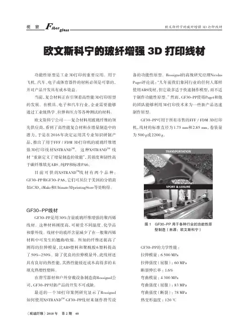
《玻璃纤维》2018年 第2期 40欧文斯科宁的玻纤增强3D 打印线材功能性原型是工业3D打印的重要应用。
用于飞机、汽车、电子或体育器件的材料必须是可靠的,并对产品开发具有成本效益。
当前,复合材料正在引领着高性能3D打印原型的发展。
在模具、电子和汽车行业,企业需要能够通过工业级热学、拉伸和压力等各种测试的材料。
欧文斯科宁公司――复合材料用玻璃纤维的领先供应商,看到了高性能复合材料在增量制造中的潜力,于是在2016年决定运用其专业知识研制产品,推出了用于FFF / FDM 3D打印机的玻璃纤维增强3D打印线材XSTRAND TM 。
这种XSTRAND TM 线材“重新定义了增量制造的效能”,其强度和韧性高于碳纤维填充ABS、纯PP和标准PA6。
目前可供的XSTRAND TM 线材有两个品种:GF30-PP和GF30-PA6,它们可从位于美国的分销商如iC3D,iMakr和Ultimate3DprintingStore等处购得。
GF30-PP线材GF30-PP是用30%含量玻璃纤维增强的聚丙烯线材。
这种材料刚度高,可耐受不同温度、化学品和紫外线。
线材中的玻纤含量减少了在一般聚丙烯材料中可发生的翘曲/收缩。
所加的纤维还提高了测得的拉伸模量,比ABS塑料和聚酰胺6塑料提高了50%-250%。
除了优良的拉伸模量外,此线材还具有良好的热性能,其热性能接近成本高得多的未填充热塑性塑料。
在滑雪器材和户外穿戴设备制造商Rossignol公司,GF30-PP对新产品的开发不可或缺。
最近的一个3D打印案例研究显示了Rossignol 如何使用XSTRAND TM GF30-PP线材来制作滑雪设备的功能性原型。
Rossignol的高级研究经理Nicolas Puget评论说:“几年前我们象同行业的任何人那样使用ABS线材,但它最多适于快速制作模型,而不适于制作功能性原型。
” 然而,GF30-PP使得Puget和他的团队能够利用3D打印技术来为一些新产品迅速制作原型。
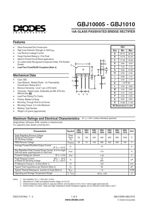
e 3Features·Glass Passivated Die Construction ·High Case Dielectric Strength of 1500V RMS ·Low Reverse Leakage Current ·Surge Overload Rating to 170A Peak ·Ideal for Printed Circuit Board Applications·UL Listed Under Recognized Component Index, File Number E94661·Lead Free Finish/RoHS Compliant (Note 4)Single phase, half wave, 60Hz, resistive or inductive load.For capacitive load, derate current by 20%.Maximum Ratings and Electrical Characteristics@ T A = 25°C unless otherwise specifiedGBJ10005 - GBJ101010A GLASS PASSIVATED BRIDGE RECTIFIER·Case:GBJ·Case Material: Molded Plastic - UL Flammability Classification Rating 94V-0·Moisture Sensitivity: Level 1 per J-STD-020C·Terminals: Plated Leads,Solderable per MIL-STD-202,Method 208·Lead Free Plating (Tin Finish).·Polarity: Molded on Body·Mounting: Through Hole for #6 Screw ·Mounting Torque: 5.0 in-lbs Maximum ·Marking: Type Number·Weight: 6.6 grams (approximate)Mechanical DataNotes: 1. Non-repetitive, for t > 1.0ms and < 8.3ms.2. Measured at 1.0 MHz and applied reverse voltage of 4.0V DC.3. Thermal resistance from junction to case per element. Unit mounted on 150 x 150 x 1.6mm copper plate heat sink.4.RoHS revision 13.2.2003. Glass and High Temperature Solder Exemptions Applied, see EU Directive Annex Notes 5 and 7.0.010.11.0100.40.81.21.61.8V ,INSTANTANEOUS FORWARD VOLTAGE (V)Fig.2Typical Forward Characteristics (per element)F I ,I N S T A N T A N E O U S F O R W A R D C U R R E N T (A )F4080120160180110100I ,P E A K F O R W A R D S U R G E C U R R E N T (A )F S M NUMBER OF CYCLES AT 60HzFig.3Maximum Non-Repetitive Surge Current101001110100C ,T O T A L C A P A C I T A N C E (p F )T V ,REVERSE VOLTAGE (V)Fig.4Typical Total Capacitance,Per ElementR 0.11.010100100020406080100120140PERCENT OF RATED PEAK REVERSE VOLTAGE (%)Fig.5Typical Reverse Characteristics24681012255075100125150I ,A V E R A G E R E C T I F I E D C U R R E N T (A )O T ,CASETEMPERATURE (C)Fig.1Forward Current Derating CurveC °Ordering Information(Note 5)Notes: 5. For packaging details, visit our website at /datasheets/ap2008.pdf.IMPORTANT NOTICEDiodes Incorporated and its subsidiaries reserve the right to make modifications,enhancements,improvements,corrections or other changes without further notice to any product herein.Diodes Incorporated does not assume any liability arising out of the application or use of any product described herein;neither does it convey any license under its patent rights,nor the rights of others.The user of products in such applications shall assume all risks of such use and will agree to hold Diodes Incorporated and all the companies whose products are represented on our website,harmless against all damages.LIFE SUPPORTDiodes Incorporated products are not authorized for use as critical components in life support devices or systems without the expressed written approval of the President of Diodes Incorporated.。
AdvisoryU.S. Departmentof TransportationCircularFederal AviationAdministrationDate: 9/8/09 AC No: 20-107BSubject: COMPOSITE AIRCRAFTSTRUCTUREInitiated by: AIR-100 Change:1 Purpose of this Advisory Circular ACThis AC sets forth an acceptable means, but notthe only means of showing compliance with the provisions of Title 14 of the Code of FederalRegulations 14 CFR parts 23, 25, 27, and 29 regarding airworthiness type certificationrequirements for composite aircraft structures involving fiber reinforced materials, e.g., carbonand glass fiber reinforced plasticsGuidance information is also presented on the closely relateddesign, manufacturing, and maintenance aspectsThe informationcontained herein is forguidance purposes and is not mandatory or regulatory in nature2 To Whom this AC AppliesThe audience of this AC may include applicants,certificate/approval holders, parts manufacturers, material suppliers, maintenance, and repairorganizations3CancellationAC 20-107A, Composite Aircraft Structure, dated April 25, 1984, is cancelled4. Related Regulations and GuidanceThe material contained herein applies to normal,utility, acrobatic, commuter, and transport category aircraft type certificated under Civil AviationRegulations CARs 3, 4b, 6, 7; and 14 CFR parts 23, 25, 27, 29; and it is produced incompliance with 14 CFR part 21, §§ 21.125, or 21.143 as may be appropriateThe sections of14 CFR, parts 23, 25, 27, and 29 applicable to each paragraph of this AC are listed in Appendix1Other supporting guidance relevant to the AC is also provided in Appendix 15Generala. The procedures outlined in this AC provide guidancematerial for composite structures,particularly those that are essential in maintaining the overall flight safety of the aircraft “criticalstructure” as defined in Appendix 2, and are considered acceptable to the FAA for showingcompliance with certification requirements of civil composite aircraftThis circular is publishedto aid in the evaluation of certification programs for composite applications and to reflect thecurrent status of composite technologyIt is expected that this circular will be modified 9/8/09 AC 20-107Bperiodically to reflect the continued evolution of composite technology and the data collectedfrom service experience and expanding applicationsb. There are factors unique to the specific composite materials and processes used for agiven applicationFor example, the environmental sensitivity, anisotropic properties, andheterogeneous nature of composites can make the determination of structural failure loads,modes, and locations difficultThe reliability of such evaluation depends on repeatablestructural details created by scaled manufacturing or repair processesThe extent of testingand/or analysis may differ for a structure depending upon the criticality to flight safety, expectedservice usage, the material and processes selected, the design margins, the failure criteria, thedatabase and experience with similar structures, and on other factors affecting a particularstructureIt is expected that these factors will be considered when interpreting this AC for useon a specific applicationc. Definitions of terms used in this AC can be found in Appendix 26. Material and Fabrication DevelopmentAll composite materials and processes used instructures are qualified through enough fabrication trials and tests to demonstrate a reproducibleand reliable designOne of the unique features of composite construction is the degree of careneeded in the procurement and processing of composite materialsThe final mechanicalbehavior of a given composite material may vary greatly depending on the processing methodsemployed to fabricate production partsSpecial care needs to be taken in controlling both thematerials being procured and how the material is processed once delivered to the fabricationfacilityRegulatory requirements in 14 CFR, parts 2X, §§ 2x.603 and 2x.605 specify the need toprocure and process materials under approved material and process specifications that control thekey parameters governing performance14 CFR, parts 2X, §§ 2x.609 and 2x.613 outlines a needto protect structures against the degradation possible in serviceThey also require that the designaccount for any changes in performance e.g., environmental and variability effects permitted bymaterial and process specificationsa. Material and Process Control 1 Specifications covering material, material processing, and fabrication procedures areestablished to ensure a basis for fabricating reproducible and reliable structureMaterialspecifications are required to ensure consistent material is being procured, and batch acceptancetesting or statistical process controls are used to ensure materialproperties do not drift over timeSpecifications covering processing procedures should be developed to ensure that repeatable andreliable structure is being manufacturedThe means of processing qualification and acceptancetests defined in each material specification should be representative of the expected applicablemanufacturing processThe process parameters for fabricating test specimens should match theprocess parameters used in manufacturing actual production parts as closely as possibleBothtest and production parts must conform to material and process specifications 2 Once the fabrication processes have been established, changes should not occurunless additional qualification, including testing of differences is completed refer to AppendixPage 2 9/8/09 AC 20-107B3It is important to establish processing tolerances; material handling and storage limits; andkey characteristics, which can be measured and tracked to judge part quality 3 Material requirements identified in procurement specifications should be based on thequalification test results for samples produced using the related process specificationsQualification data must cover all properties important to the control of materials composites andadhesives and processes used for production of composite structureCarefully selectedphysical, chemical, and mechanical qualification tests are used to demonstrate the formulation,stiffness, strength, durability, and reliability of materials and processes for aircraft applicationsIt is recommended that material suppliers work closely with airframe manufacturers to properlydefine material requirements 4 To provide an adequate design database, environmental effects on critical propertiesof the material systems and associated processes should be establishedIn addition to testing inan ambient environment, variables should include extreme service temperature and moisturecontent conditions and effects of long-term durabilityQualification tests for environmentaleffects and long-term durability are particularly important when evaluating the materials,processes, and interface issues associated with structural bonding refer to paragraph 6.c forrelated guidance 5 Key characteristics and processing parameters will be monitored for in-processquality controlThe overall quality control plan required by the certifying agency should involveall relevant disciplines, i.e., engineering, manufacturing, and quality controlA reliable qualitycontrol system should be in place to address special engineering requirements that arise inindividual parts or areas as a result of potential failure modes, damage tolerance and flaw growthrequirements, loadings, inspectability, and local sensitivities to manufacture and assembly 6 The discrepancies permitted by the specifications should also be substantiated byanalysis supported by test evidence, or tests at the coupon, element or subcomponent levelFornew production methods, repeatable processes should be demonstrated at sufficient structuralscale in a way shown to be consistent with the material and process qualification tests anddevelopment of the associated specificationsThis will requireintegration of the technical issuesassociated with product design and manufacturing details prior to a large investment in structuraltests and analysis correlationIt will also ensure the relevance of quality control proceduresdefined to control materials and processes as related to the product structural details 7 The FAA does not generally certify materials and processesHowever, the materialsand processes may be accepted as part of a particular aircraft product certificationAppropriatecredit may be given to organizations using the same materials and processes in similarapplications subject to substantiation and applicabilityIn some cases, material and processinginformation may become part of accepted shared databases used throughout the industryNewusers of shared qualification databases must control the associated materials and processesthrough proper use of the related specifications and demonstrate their understanding byperforming equivalency sampling tests for key propertiesMaterials and processes used intechnical standard order TSO articles or authorizations must also be qualified and controlledPage 3 9/8/09 AC 20-107Bb. Manufacturing Implementation 1 Process specifications and manufacturing documentation are needed to control composite fabrication and assemblyThe environment and cleanliness of facilities are controlledto a level validated by qualification and proof of structure testingRaw and ancillary materialsare controlled to specification requirements that are consistent with material and processqualificationsParts fabricated meet the production tolerances validated in qualification, designdata development, and proof of structure testsSome key fabrication process considerationsrequiring such control include material handling and storage; laminate layup and bagging orother alternate process steps for non-laminated material forms and advanced processes; matingpart dimensional tolerance control; part cure thermal management; machining and assembly;cured part inspection and handling procedures; and technician training for specific material,processes, tooling and equipment 2 Thorough manufacturing records are needed to support parts acceptance andallowable discrepancies defects, damage and anomaliesSubstantiating data is needed tojustify all known defects, damage and anomalies allowed to remain in service without rework orrepairManufacturing records are also needed for all substantiated design and process changes 3 New suppliers of parts for previously certified aircraft products are qualified bymanufacturing trials and quality assessments to ensure equivalent production and repeatabilitySome destructive inspection of critical structural details is needed for manufacturing flaws thatare not end item inspectable and require process controls to ensure reliable fabricationc. Structural BondingBonded structures include multiple interfaces e.g., composite-to-composite, composite-to-metal, or metal-to-metal, where at least one of the interfaces requiresadditional surface preparation prior to bondingThe general nature of technical parameters thatgovern different types of bonded structures are similarA qualified bonding process isdocumented after demonstrating repeatable and reliable processing steps such as surfacepreparationIt entails understanding the sensitivity of structural performance based uponexpected variation permitted per the processCharacterization outside the process limits isrecommended to ensure process robustnessIn the case of bonding composite interfaces, aqualified surface preparation of all previously cured substrates is needed to activate their surfacefor chemical adhesionAll metal interfaces in a bonded structure also have chemically activatedsurfaces created by a qualified preparation processMany technical issues for bonding requirecross-functional teams for successful applicationsApplications require stringent process controland a thorough substantiation of structural integrity 1 Many bond failures and problems in service have been traced to invalid qualificationsor insufficient quality control of production processesPhysical and chemical tests may be usedto control surface preparation, adhesive mixing, viscosity, and cureproperties e.g., density,degree of cure, glass transition temperatureLap shear stiffness and strength are commonmechanical tests for adhesive and bond process qualificationShear tests do not provide areliable measure of long-term durability and environmental degradation associated with poorbonding processes i.e., lack of adhesionSome type of peel test has proven more reliable forevaluating proper adhesionWithout chemical bonding, the so-called condition of a “weakPage 4 9/8/09 AC 20-107Bbond” exists when the bonded joint is either loaded by peel forces or exposed to the environmentover a long period of time, or bothAdhesion failures, which indicate the lack of chemicalbonding between substrate and adhesive materials, are considered an unacceptable failure modein all test typesMaterial or bond process problems that lead to adhesion failures are solvedbefore proceeding with qualification tests 2 Process specifications are needed to control adhesive bonding in manufacturing andrepairA “process control mentality,” which includes a combination of in-process inspectionsand tests, has proven to be the most reliable means of ensuring the quality of adhesive bondsThe environment and cleanliness of facilities used for bonding processes are controlled to a levelvalidated by qualification and proof of structure testingAdhesives and substrate materials arecontrolled to specification requirements that are consistent with material and bond processqualificationsThe bonding processes used for production and repair meet tolerances validatedin qualification, design data development, and proof of structure testsSome key bondfabrication process considerations requiring such control include material handling and storage;bond surface preparation; mating part dimensional tolerance control; adhesive application andclamp-up pressure; bond line thickness control; bonded part cure thermal management; curedpart inspection and handling procedures; and bond technician training for specific material,processes, tooling, and equipmentBond surface preparation and subsequent handling controlsleading up to the bond assembly and cure must be closely controlled in time and exposure toenvironment and contamination 3 14 CFR § 23.573a sets forth requirements for substantiating the primary compositeairframe structures, including considerations for damage tolerance, fatigue, and bonded jointsAlthough this is a small airplane rule, the same performance standards are normally expectedwith transport and rotorcraft category aircraft via special conditions and issue papers a For any bonded joint, § 23.573a5 states in part: "the failure of which wouldresult in catastrophic loss of the airplane, the limit load capacity must be substantiated by one ofthe following methods?i The imum disbonds of each bonded joint consistent with thecapability to withstand the loads in paragraph a3 of this section must be determined byanalysis, tests, or bothDisbonds of each bonded joint greater than this must be prevented bydesign features; or ii Proof testing must be conducted on eachproduction article that willapply the critical limit design load to each critical bonded joint; or iii Repeatable and reliablenon-destructive inspection techniques must be established that ensure the strength of each joint." b These options do not supersede the need for a qualified bonding process andrigorous quality controls for bonded structuresFor example, fail safety implied by the firstoption is not intended to provide adequate safety for the systematic problem of a bad bondingprocess applied to a fleet of aircraft structuresInstead, it gives fail safety against bondingproblems that may occasionally occur over local areas e.g., insufficient local bond contactpressure or contaminationPerforming static proof tests to limit load, which is the secondoption, may not detect weak bonds requiring environmental exposure and time to degradebonded joint strengthThis issue should be covered by adequately demonstrating that qualifiedbonding materials and processes have long-term environmental durabilityFinally, the thirdoption is open for future advancement and validation of non-destructive inspection NDIPage 5 9/8/09 AC 20-107Btechnology to detect weak bonds, which degrade over time and lead to adhesion failuresSuchtechnology has not been reliably demonstrated at a production scale to date 4 Adhesion failures found in production require immediate action to identify thespecific cause and isolate all affected parts and assemblies for dispositionAdhesion failuresdiscovered in service require immediate action to determine the cause, to isolate the affectedaircraft, and to conduct directed inspection and repairDepending on the suspected severity ofthe bonding problem, immediate action may be required to restore the affected aircraft to anairworthy conditiondEnvironmental ConsiderationsEnvironmental design criteria should be developed thatidentify the critical environmental exposures, including humidity and temperature, to which thematerial in the application under evaluation may be exposedService data e.g., moisture contentas a function of time in service can be used to ensure such criteria are realisticIn addition, thepeak temperatures for composite structure installed in close proximity to aircraft systems thatgenerate thermal energy need to be identified for worst-case normal operation and system failurecasesEnvironmental design criteria are not required where existing data demonstrate that。
国外机车前风挡玻璃抗冲击测试标准解析及应对策略随着机车运输行业的不断发展,对于机车前风挡玻璃的品质和安全性要求也越来越高。
在机车运输当中,机车前风挡玻璃往往承担着很大的安全责任,因此对于其抗冲击的能力也提出了更高的要求。
本文将从国外机车前风挡玻璃抗冲击测试的标准出发,针对其测试标准所存在的问题进行分析,并提出应对策略。
目前国外机车前风挡玻璃的抗冲击测试标准主要有FMVSS-205、ECE-R43等标准。
1. FMVSS-205标准FMVSS-205标准是美国机动车安全标准的一部分,是对于机动车上玻璃的要求。
该标准对于前挡风玻璃的抗冲击能力进行了测试,包括静态荷载、动态荷载、钱带荷载等。
其中静态荷载测试是将铝合金气枕椅上的一吨重的钢球垂直落下,检查玻璃是否破碎。
动态荷载测试则是模拟车辆行驶路面上的颠簸和碰撞情况,通过将钢球从不同高度落下来进行测试。
钱带荷载测试则是模拟车辆在高速公路上行驶时的强风荷载,并对玻璃进行测试。
2. ECE-R43标准ECE-R43标准是欧洲经济委员会采用的对于汽车前挡风玻璃的要求标准。
该标准将对前挡风玻璃进行耐冲击测试,包括钢球试验和弹珠试验。
钢球试验是测试玻璃能否承受一定速度和重量的钢球的撞击,弹珠试验则是测试玻璃能否承受一定速度和射程的金属球的撞击。
二、存在问题虽然国外机车前风挡玻璃抗冲击的测试标准相对严格,但是仍然存在以下几个问题:1. 国内乃至国际之间抗冲击测试标准缺乏统一性。
目前不同国家、不同地区对于机车前风挡玻璃的抗冲击测试标准要求不一,缺乏统一标准,这给机车运输行业带来了不必要的麻烦和混乱。
2. 部分测试标准存在不足。
FMVSS-205标准在测试过程中只测试了前挡风玻璃的抗冲击能力,而对于侧窗玻璃的测试较为薄弱,这与实际使用中的安全需要还有一定差距。
同时,ECE-R43标准的测试方法也有待完善,因为无法对于玻璃碎片的飞溅情况进行预先控制。
三、应对策略针对存在的问题,我们可以从以下几个方面进行应对:1. 推进国际化标准建设,制定统一的抗冲击测试标准。
第50卷第6期2022年6月同济大学学报(自然科学版)
JOURNALOFTONGJIUNIVERSITY(NATURALSCIENCE)
Vol.50No.6
Jun.2022
论文拓展介绍
S32001双相型不锈钢高温力学性能试验楼国彪1,2,杨未1,陈武龙1,陶宇超1,王美南3(1.同济大学土木工程学院,上海200092;2.同济大学土木工程防灾国家实验室,上海200092;3.远大可建科技有限公司,湖南长沙430121)
摘要:对S32001双相型不锈钢进行了高温稳态拉伸试验研究,得到了高温下初始弹性模量、名义屈服强度、抗拉强度、断后伸长率等主要力学性能指标及其变化规律;利用试验数据研究了Rasmussen模型和Gardner模型的适用性,并基于Rasmussen模型提出了S32001不锈钢硬化指数的计算公式,
建立了高温下不锈钢材料本构关系表达式;对比分析了S32001不锈钢与其他种类不锈钢及Q235B结构钢的高温力
学性能。研究表明,S32001不锈钢的屈服强度和极限强度随温度升高下降,600℃时低于常温时的50%,但高温下材料强度明显高于S30408不锈钢,具有更加优越的抗火性能。该研究结果可用于结构受火性能研究和抗火设计。
关键词:双相型不锈钢;力学性能;本构关系;高温中图分类号:TU511.3文献标志码:A
ExperimentalInvestigationonMechanicalPropertiesofS32001DuplexStainlessSteelatElevatedTemperatures
LOUGuobiao1,2,YANGWei1,CHENWulong1,TAO
Yuchao1,WANGMeinan3
(1.CollegeofCivilEngineering,TongjiUniversity,Shanghai200092,China;2.StateKeyLaboratoryforDisasterReductioninCivilEngineering,TongjiUniversity,Shanghai200092,China;3.BroadSustainableBuilding,Changsha430121,Hunan,China)

材料科学与工程专业英语匡少平课后翻译答案精编W O R D版IBM system office room 【A0816H-A0912AAAHH-GX8Q8-GNTHHJ8】Alloy合金applied force作用力amorphous materials不定形材料artificial materials人工材料biomaterials生物材料biological synthesis生物合成biocompatibility生物相容性brittle failure脆性破坏carbon nanotub e碳纳米管carboxylic acid羟酸critical stress临近应力dielectric constant介电常数clay minera l粘土矿物cross-sectional area横截面积critical shear stress临界剪切应力critical length临界长度curing agent固化剂dynamic or cyclic loading动态循环负载linear coefficient of themal expansio n性膨胀系数electromagnetic radiation电磁辐射electrodeposition电极沉积nonlocalizedelectrons游离电子electron beam lithography电子束光刻elasticity 弹性系数electrostation adsorption静电吸附elastic modulus弹性模量elastic deformation弹性形变elastomer弹性体engineering strain工程应变crystallization 结晶fiber-optic光纤维Ethylene oxide环氧乙烷fabrication process制造过程glass fiber玻璃纤维glass transition temperature 玻璃化转变温度heat capacity热熔Hearing aids助听器integrated circuit集成电路Interdisplinary交叉学科intimate contact密切接触inert substance惰性材料implant移植individual application个体应用deformation局部形变mechanical strength机械强度mechanical attrition机械磨损Mechanical properties力学性Materials processing材料加工质mechanical behavior力学行为magnetic permeability磁导率magnetic hybrid technique混合技术induction磁感应mass per unit of volume单位体积质量monomer identity单体种类molecular mass分子量microsphere encapsulation technique微球胶囊技术macroscopical宏观的naked eye 肉眼nonlocalized nanoengineered materials纳米材料nanostructured materials纳米结构材料nonferrous metal有色金属线nucleic acid核酸nanoscale纳米尺度Nanotechnology纳米技术nanobiotechnology纳米生物技术nanocontact printing纳米接触印刷optical property光学性质optoelectronic device光电设备oxidation degradation 氧化降解piezoelectric ceramics压电陶瓷Relative density相对密度stiffnesses刚度sensor传感材料semiconductors半导体specific gravity比重shear 剪切Surface tention表面张力self-organization自组装static loading静载荷stress area应力面积stress-strain curves应力应变曲线sphere radius球半径submicron technique亚微米技术substrate衬底supramolecalar超分子sol-gel method溶胶凝胶法thermal/electrical conductivity 热/点导率thermoplastic materials热塑性材料Thermosetting plastic热固性塑料thermal motion热运动toughness test韧性试验tension张力torsion扭曲Tensile Properties拉伸性能Two-dimentional nanostructure二维纳米结构Tissue engineering组织工程transplantation of organs器官移植the service life使用寿命the longitudinal direction纵向the initial length of the materials初始长度the acceleration gravity重力加速度the normal vertical axis垂直轴the surface to volume ratio 比表面密度the burgers vector伯格丝矢量the mechanics and dynamics of tissues 组织力学和动力学phase transformation temperature相转变温度plastic deformation塑性形变Pottery陶瓷persistence length余晖长度polymer synthesis聚合物合成Polar monomer记性单体polyelectrolyte高分子电解质pinning point钉扎点plasma etching 等离子腐蚀pharmacological acceptability药理接受性pyrolysis高温分解ultrasonic treatment超射波处理yield strength屈服强度vulcanization硫化1-1:直到最近,科学家才终于了解材料的结构要素与其特性之间的关系。
CompTest2006compTest2006compTest2006Progressive Damage Modeling In Fiber-ReinforcedMaterialsIreneusz Lapczyk, Juan HurtadoOutlineOverview of Damage Model for Fiber-Reinforced Materials ExampleDamage Model for Fiber-Reinforced Materials: OverviewThe damage in the material is anisotropicFour different failure modes are taken into account: fiber tension, fiber compression, matrix tension, matrix compressionThe behavior of the undamaged material is linearly elasticThe model must be used with elements with a plane stress formulation (plane stress, shell, continuum shell, and membrane elements)Post-localization response is regularized (Crack Band Model)The model can be used in conjunction with a viscous regularization scheme to improve the convergence rate in the softening regimeDamage Initiation (Hashin’s criteria)10,ˆˆ212211≤≤⎟⎠⎞⎜⎝⎛+⎟⎠⎞⎜⎝⎛=ασασwhere S X f L T I MODE I: fiber tensionMODE II: fiber compression MODE III: matrix tensionMODE IV: matrix compression211ˆ⎟⎠⎞⎜⎝⎛=C II X f σ212222ˆˆ⎟⎠⎞⎜⎝⎛+⎟⎠⎞⎜⎝⎛=L T IIIS Y f σσ212222222ˆˆ122ˆ⎟⎠⎞⎜⎝⎛+⎥⎥⎦⎤⎢⎢⎣⎡−⎟⎟⎠⎞⎜⎜⎝⎛+⎟⎠⎞⎜⎝⎛=L C TC T IVS Y S Y S f σσσstrengthsmaterial ,,,,,−CT C T T L Y Y X X S S (1)(2)(3)(4)Damaged Material Response (Matzenmiller, Lubliner, Taylor)operatordamage −M M σσ=ˆ⎥⎥⎥⎥⎥⎥⎥⎦⎤⎢⎢⎢⎢⎢⎢⎢⎣⎡−−−=s mfd d d11000110011M (1)Effective Stress(2)variablesdamage ,,−s m f d d dDamaged Material Response, cont.()()()()mc mt fc ft s d d d d d −−−−−=11111()()()⎥⎥⎥⎥⎥⎥⎥⎦⎤⎢⎢⎢⎢⎢⎢⎢⎣⎡−−−−−=G d E d E E Ed s m f110001101121122211ννH moduliundamaged ,,21−s G E E Damaged Elasticity Matrix:()()()()()()()⎥⎥⎥⎦⎤⎢⎢⎢⎣⎡−−−−−−−=G d D E d E d d Ed d E d D s m m f mff 10001110111122121211ννC ()()0111where2112>−−−=ννm f d d D (1)(2)Damaged Compliance Matrix:ratioss Poisson',2112−ννDamaged Material Response, cont.()s mc mt fcft d G E d d E d d E G −+−⎟⎟⎠⎞⎜⎜⎝⎛−−+−+⎟⎟⎠⎞⎜⎜⎝⎛−−+−=111211121212122111222222222112111σσσνσσσσ0mod 1≥=∑=esnumber i ii d Y Dforcesmic thermodyna are whereii d GY ∂∂=(1)(2)Gibbs Free Energy:Energy Dissipation:()2as every for defined operator,bracket Macauley is whereαααα+=ℜ∈Damage EvolutionThe modeling approach is a generalization of that used to model cohesiveelements, which is based on the work of C. Davila and P. Camanho The evolution law is based on the energy dissipated during the process Linear material softening is assumed()()00eqfeq eq eq eq f eqd δδδδδδ−−=Figure 1.(1)equivalent displacementequivalent stressABCGcδeqo δeqfEquivalent Displacements and Stresses11δδ−=fc eq fceqct eq δδσσ1111−−=212222δδδ+=mt eq 212211αδδδ+=ft eqfteqft eqδδασδσσ12121111+=mteq mt eqδδσδσσ12122222+=212222δδδ+−=mc eq mc eqmc eqδδσδσσ12122222+−−=Fiber Tensile Mode Fiber Compressive Mode Matrix Tensile Mode Matrix Compressive Mode–is the characteristic lengthcL and whereijc ij L εδ=Damage Evolution: ProcedureIf eqeq σδ,02eqI ffeqG σδ= Evaluate the initiation criterion,Compute equivalent displacement and stress,Compute equivalent displacement and stress at the onset of damageStoreCompute equivalent displacement at full damageUpdate the damage variableIeqIeqf f eq eqσσδδ==and ()()⎟⎟⎠⎞⎜⎜⎝⎛−−=00, I ,max d eq feq eq eq f eq OLD I eq d δδδδδδ00and eqeq σδMesh DependenceExample: uniaxialtensionFigure 1. Bar subjected to axial loadFigure 2. Localization of deformationFigure 3. Force-displacement for different discretizationsthe energy dissipated is specified per unit volume the results are mesh dependentdeformation localizes into one layer of elementsMesh Dependency, cont.Figure 1.The energy dissipated is regularized using Crack Band Model (Bazant and Oh)The energy dissipated, G f , is expressed per unit area instead of per unit volume Characteristic length, L c , is introduced, computed asL c = √A I , where A I is the area at an integration pointThe post-localization stress-displacement response is computed correctlyViscous Regularization()ννηftft ftft d d d −=1 ()ννηfcfc fcfc d d d −=1 ννννmc mt fc ft d d d d ,,,-are used to compute damaged stiffness matrixηft , ηfc ,ηmt ,ηmc -are viscosities()ννηmtmt mtmt d d d −=1 ()ννηmcmc mcmc d d d −=1 (1a-b)(2a-b)Generalization of the Duvaut-Lions regularization modelViscous Regularization, cont.Updating “Regularized”Damage VariablesJacobianmodedamage a denotes I where ,000t vI I I tt I I tt vI d td tt dΔ++Δ+Δ=Δ+Δ+ηηηttd d I I IvI Δ+Δ∂∂∂∂+=∂∂∑ηεεC C εσd d (1)(2)ttd d I I v I Δ+Δ=∂∂ηViscous Regularization, cont.energyfree −ψ()vI d d d C C =()()00002t tt tt tD E ψψ+−Δ+=ΔΔ+Δ+εεC εC d d Viscous Energy DissipationDamage Energy()()()()εεC εC εεC εC 0d 0dd d Δ+−Δ+=ΔΔ+Δ+220000tt t tt tV E ()I d 0d0d C C =(1)(2)OutputInitiation Criteria VariablesHSNFTCRT –tensile fiber Hashin’s criterionHSNFCCRT –compressive fiber Hashin’s criterionHSNMTCRT –tensile matrix Hashin’s criterionHSNMCCRT –compressive matrix Hashin’s criterionDamage VariablesDAMAGEFT –tensile fiber damageDAMAGEFC –compressive fiber damageDAMAGEMT –tensile matrix damageDAMAGEMC –compressive matrix damageDAMAGESHR -shear damageStatusSTATUS –element status (1 –present, 0 –removed)EnergiesDamage energy (ALLDMD,DMENER,ELDMD,EDMDDEN) Viscous regularization (ALLCD, CENER, ELCD, ECDDEN)Example: Failure of Blunt Notched Fiber Metal Laminatesyxz1/8 part model50 mm300 mm1.406 mmd = 4.8 mmPlate GeometryExample: Failure of Blunt Notched Fiber Metal LaminatesThrough-thickness view of the laminateExample: ResultsFigure 1. Fiber damage patternFigure 2. Load-displacement curveExample: ResultsFigure 1. Matrix tension damage pattern Figure 2. Matrix compression damage patternExample: Energy dissipationFigure 1.Figure 2.Example: ResultsBlunt Notch Strength (MPa) for Different Viscosities 446454.2461.3466.6ηf =0.00025ηf =0.0005ηf =0.001Experimental Results (De Vries, 2001)Numerical Results (SC8R, 0ºangle)。
DOI: 10.1126/science.1220854, 773 (2013);339 Science et al.Marc André Meyers ConnectionsStructural Biological Materials: Critical Mechanics-MaterialsThis copy is for your personal, non-commercial use only.clicking here.colleagues, clients, or customers by , you can order high-quality copies for your If you wish to distribute this article to othershere.following the guidelines can be obtained by Permission to republish or repurpose articles or portions of articles): May 1, 2013 (this information is current as of The following resources related to this article are available online at/content/339/6121/773.full.html version of this article at:including high-resolution figures, can be found in the online Updated information and services, /content/339/6121/773.full.html#ref-list-1, 12 of which can be accessed free:cites 51 articles This article/cgi/collection/mat_sci Materials Sciencesubject collections:This article appears in the following registered trademark of AAAS.is a Science 2013 by the American Association for the Advancement of Science; all rights reserved. The title Copyright American Association for the Advancement of Science, 1200 New York Avenue NW, Washington, DC 20005. (print ISSN 0036-8075; online ISSN 1095-9203) is published weekly, except the last week in December, by the Science o n M a y 1, 2013w w w .s c i e n c e m a g .o r g D o w n l o a d e d f r o mStructural BiologicalMaterials:CriticalMechanics-Materials ConnectionsMarc AndréMeyers,1,2*Joanna McKittrick,1Po-Yu Chen3Spider silk is extraordinarily strong,mollusk shells and bone are tough,and porcupine quills and feathers resist buckling.How are these notable properties achieved?The building blocks of the materials listed above are primarily minerals and biopolymers,mostly in combination;the first weak in tension and the second weak in compression.The intricate and ingenious hierarchical structures are responsible for the outstanding performance of each material.Toughness is conferred by the presence of controlled interfacial features(friction,hydrogen bonds,chain straightening and stretching);buckling resistance can be achieved by filling a slender column with a lightweight foam.Here,we present and interpret selected examples of these and other biological materials.Structural bio-inspired materials design makes use of the biological structures by inserting synthetic materials and processes that augment the structures’capability while retaining their essential features.In this Review,we explain this idea through some unusual concepts.M aterials science is a vibrant field of in-tellectual endeavor and research.Thisfield applies physics and chemistry, melding them in the process,to the interrela-tionship between structure,properties,and perform-ance of complex materials with technological applications.Thus,materials science extends these rigorous scientific disciplines into complex ma-terials that have structures providing properties and synergies beyond those of pure and simple solids.Initially geared at synthetic materials,ma-terials science has recently extended its reach into biology,especially into the extracellular matrix, whose mechanical properties are of utmost im-portance in living organisms.Some of the semi-nal work and important contributions in this field are either presented or reviewed in(1–5).There are a number of interrelated features that define biological materials and distinguish them from their synthetic counterparts[inspired by Arzt(6)]: (i)Self-assembly.In contrast to many synthetic processes to produce materials,the structures are assembled from the bottom up,rather than from the top down.(ii)Multi-functionality.Many com-ponents serve more than one purpose.For exam-ple,feathers provide flight capability,camouflage, and insulation,whereas bones provide structural framework,promote the growth of red blood cells, and provide protection to the internal organs.(iii) Hierarchy.Different,organized scale levels(nano-to ultrascale)confer distinct and translatable prop-erties from one level to the next.We are starting to develop a systematic and quantitative understandingof this hierarchy by distinguishing the character-istic levels,developing constitutive descriptionsof each level,and linking them through appro-priate and physically based equations,enabling afull predictive understanding.(iv)Hydration.Theproperties are highly dependent on the level ofwater in the structure.There are some exceptions,such as enamel,but this rule applies to mostbiological materials and is of importance to me-chanical properties such as strength(which isdecreased by hydration)and toughness(which isincreased).(v)Mild synthesis conditions.Themajority of biological materials are fabricated atambient temperature and pressure as well as in anaqueous environment,a notable difference fromsynthetic materials fabrication.(vi)Evolution andenvironmental constraints.The limited availabil-ity of useful elements dictates the morphologyand resultant properties.The structures are notnecessarily optimized for all properties but arethe result of an evolutionary process leading tosatisfactory and robust solutions.(vii)Self-healingcapability.Whereas synthetic materials undergodamage and failure in an irreversible manner,biological materials often have the capability,due to the vascularity and cells embedded in thestructure,to reverse the effects of damage byhealing.The seven characteristics listed above arepresent in a vast number of structures.Nevertheless,the structures of biological materials can bedivided into two broad classes:(i)non-mineralized(“soft”)structures,which are composed of fibrousconstituents(collagen,keratin,elastin,chitin,lignin,and other biopolymers)that display widelyvarying mechanical properties and anisotropiesdepending on the function,and(ii)mineralized(“hard”)structures,consisting of hierarchicallyassembled composites of minerals(mainly,butnot solely,hydroxyapatite,calcium carbonate,and amorphous silica)and organic fibrous com-ponents(primarily collagen and chitin).The mechanical behavior of biological con-stituents and composites is quite diverse.Bio-minerals exhibit linear elastic stress-strain plots,whereas the biopolymer constituents are non-linear,demonstrating either a J shape or a curvewith an inflection point.Foams are characterizedby a compressive response containing a plastic orcrushing plateau in which the porosity is elim-inated.Many biological materials are compositeswith many components that are hierarchicallystructured and can have a broad variety of con-stitutive responses.Below,we present some of thestructures and functionalities of biological ma-terials with examples from current research.Here,we focus on three points:(i)How high tensilestrength is achieved(biopolymers),(ii)how hightoughness is attained(composite structures),and(iii)how bending resistance is achieved in light-weight structures(shells with an interior foam).Structures in Tension:Importance of BiopolymersThe ability to sustain tensile forces requires aspecific set of molecular and configurational con-formations.The initial work performed on exten-sion should be small,to reduce energy expenditure,whereas the material should stiffen close to thebreaking point,to resist failure.Thus,biopolymers,such as collagen and viscid(catching spiral)spidersilk,have a J-shaped stress-strain curve where mo-lecular uncoiling and unkinking occur with con-siderable deformation under low stress.This stiffening as the chains unfurl,straighten,stretch,and slide past each other can be repre-sented analytically in one,two,and three dimen-sions.Examples are constitutive equations initiallydeveloped for polymers by Ogden(7)and Arrudaand Boyce(8).An equation specifically proposedfor tissues is given by Fung(3).A simpler for-mulation is given here;the slope of the stress-strain(s-e)curve increases monotonically with strain.Thus,one considers two regimes:(i)unfurlingand straightening of polymer chainsd sd eºe nðn>1Þð1Þand(ii)stretching of the polymer chain backbonesd sd eºEð2Þwhere E is the elastic modulus of the chains.Thecombined equation,after integrating Eqs.1and2,iss=k1e n+1+H(e c)E(e–e c)(3)Here k1is a parameter,and H is the Heavisidefunction,which activates the second term at e=e c,where e c is a characteristic strain at whichcollagen fibers are fully extended.Subsequent straingradually becomes dominated by chain stretch-ing.The computational results by Gautieri et al.(9)on collagen fibrils corroborate Eq.3for n=1.This corresponds to a quadratic relation between1Department of Mechanical and Aerospace Engineering andMaterials Science and Engineering Program,University ofCalifornia,San Diego,La Jolla,CA92093,USA.2Department ofNanoengineering,University of California,San Diego,La Jolla,CA92093,USA.3Department of Materials Science and En-gineering,National Tsing Hua University,Hsinchu30013,Taiwan,Republic of China.*To whom correspondence should be addressed.E-mail:mameyers@ SCIENCE VOL33915FEBRUARY2013773o n M a y 1 , 2 0 1 3 w w w . s c i e n c e m a g . o r g D o w n l o a d e d f r o mstress and strain (s ºe 2),which has the char-acteristic J shape.Collagen is the most important structural bio-logical polymer,as it is the key component in many tissues (tendon,ligaments,skin,and bone),as well as in the extracellular matrix.The de-formation process is intimately connected to the different hierarchical levels,starting with the poly-peptides (0.5-nm diameter)to the tropocollagen molecules (1.5-nm diameter),then to the fibrils (~40-to 100-nm diameter),and finally to fibers (~1-to 10-m m diameter)and fascicles (>10-m m diameter).Molecular dynamics computations (9)of entire fibrils show the J -curve response;these computational predictions are well matched to atomic force microscopy (AFM)(10),small-angle x-ray scattering (SAXS)(11),and experiments by Fratzl et al .(12),as shown in Fig.1A.The effect of hydration is also seen and is of great impor-tance.The calculated density of collagen de-creases from 1.34to 1.19g/cm 3with hydration and is accompanied by a decrease in the Young ’s modulus from 3.26to 0.6GPa.The response of silk and spider thread is fascinating.As one of the toughest known ma-terials,silk also has high tensile strength and extensibility.It is composed of b sheet (10to 15volume %)nanocrystals [which consist of highly conserved poly-(Gly-Ala)and poly-Ala domains]embedded in a disordered matrix (13).Figure 1B shows the J -shape stress-strain curve and molecular configurations for the crystalline domains in silkworm (Bombyx mori )silk (14).Similar to collagen,the low-stress region corre-sponds to uncoiling and straightening of the pro-tein strands.This region is followed by entropic unfolding of the amorphous strands and then stiffening due to load transfer to the crystalline b sheets.Despite the high strength,the major mo-lecular interactions in the b sheets are weak hy-drogen bonds.Molecular dynamics simulations,Fig.1.Tensile stress-strain relationships in bio-polymers.(A )J -shaped curve for hydrated and dry collagen fibrils obtained from molecular dynamics (MD)simulations and AFM and SAXS studies.At low stress levels,considerable stretching occurs due to the uncrimping and unfolding of molecules;at higher stress levels,the polymer backbone stretches.Adapted from (9,12).(B )Stretching of dragline spider silk and molecular schematic of the protein fibroin.At low stress levels,entropic effects domi-nate (straightening of amorphous strands);at higher levels,the crystalline parts sustain the load.(C )Mo-lecular dynamics simulation of silk:(i)short stack and (ii)long stack of b -sheet crystals,showing that a higher pullout force is required in the short stack;for the long stack,bending stresses become im-portant.Hydrogen bonds connect b -sheet crystals.Adapted from (14).(D )Egg whelk case (bioelastomer)showing three regions:straightening of the a helices,the a helix –to –b sheet transformation,and b -sheet extension.A molecular schematic is shown.Adapted from (18).300.000.2Yield pointEntropic unfoldingMD simulationsStick slipStiffening β-crystal123456700012345670102030405050010001500200025050075010001250150017500.40.60.80.010.020.030.040.05MD wet (Gautieri et al)SAXS (Sasaki and Odajima)AFM (Aladin et al)MD dry (Gautieri et al)2520151050S t r e s s (M P a )S t r e s s(M P a )StrainABCDStrain (m/m)Length (nm)Length (nm)Stick-slip deformation (robust)"brittle" fracture (fragile)i iiP u l l -o u t f o r c e (p N )00.20.4Native state Unloading: reformation of α-helicesDomain 4: Extension andalignmentof β-sheets0.60.8ε=0ε4ε=01.0012345StrainS t r e s s (M P a )E n e r g y /v o l u m e (k c a l /m o l /n m 3)L e n g t hI I II II III IIIIVIVFDomain 3: Formation of β-sheetsfrom random coilsε3Domain 2: Extension of random coilsε2Domain 1: Unraveling of α-helicesinto random coilsε1Toughness (MD)Resilience (MD)T=-1°C T=20°C T=40°C T=60°C T=80°C15FEBRUARY 2013VOL 339SCIENCE 774REVIEWo n M a y 1, 2013w w w .s c i e n c e m a g .o r g D o w n l o a d e d f r o mshown in Fig.1C,illustrate an energy dissipative stick-slip shearing of the hydrogen bonds during failure of the b sheets (14).For a stack with a height L ≤3nm (left-hand side of Fig.1C),the shear stresses are more substantial than the flex-ure stresses,and the hydrogen bonds contribute to the high strength obtained (1.5GPa).How-ever,if the stack of b sheets is too high (right-hand side of Fig.1C),it undergoes bending with tensile separation between adjacent sheets.The nanoscale dimension of the b sheets allows for a ductile instead of brittle failure,resulting in high toughness values of silk.Thus,size affects the mechanical response considerably,changing the deformation characteristics of the weak hydro-gen bonds.This has also been demonstrated in bone (15–17),where sacrificial hydrogen bonds between mineralized collagen fibrils contribute to the excellent fracture resistance.Other biological soft materials have more complex responses,marked by discontinuities in d s /d e .This is the case for wool,whelk eggs,silks,and spider webs.Several mechanisms are responsible for this change in slope;for instance,the transition from a -to b -keratin,entropic changes with strain (such as those prevalent in rubber,where chain stretching and alignment decrease entropy),and others.The example of egg whelk is shown in Fig.1D (18).In this case,there is a specific stress at which a -keratin heli-ces transform to b sheets,with an associated change in length.Upon unloading,the reverse occurs,and the total reversible strain is,therefore,extensive.This stress-induced phase transforma-tion is similar to what occurs in shape-memory alloys.Thus,this material can experience sub-stantial reversible deformation (up to 80%)in a reversible fashion,when the stress is raised from 2to 5MPa,ensuring the survival of whelk eggs,which are continually swept by waves.These examples demonstrate the distinct properties of biopolymers that allow these ma-terials to be strong and highly extensible with distinctive molecular deformation characteristics.However,many interesting biological materials are composites of flexible biopolymers and stiff minerals.The combination of these two constit-uents leads to the creation of a tough material.Imparting Toughness:Importance of Interfaces One hallmark property of most biological com-posites is that they are tough.Toughness is defined as the amount of energy a material ab-sorbs before it fails,expressed asU ¼∫e fs d eð4Þwhere U is the energy per volume absorbed,s is the stress,e is the strain,and e f is the failure strain.Tough materials show considerable plastic deformation (or permanent damage)coupled with considerable strength.This maximizes the integral expression in Eq.4.Biological com-posite materials (for example,crystalline and noncrystalline components)have a plethora oftoughening mechanisms,many of which depend on the presence of interfaces.As a crack im-pinges on an interface or discontinuity in the material,the crack can be deflected around the interface (requiring more energy to propagate than a straight crack)or can drive through it.The strength of biopolymer fibers in tension im-pedes crack opening;bridges between micro-cracks are another mechanism.The toughening mechanisms have been divided into intrinsic (ex-isting in the material ahead of crack)and extrinsic (generated during the progression of failure)cat-egories (19).Thus,toughening is accomplished by a wide variety of stratagems.We illustrate this concept for four biological materials,shown in Fig.2.All inorganic materials contain flaws and cracks,which reduce the strength from the theo-retical value (~E /10to E /30).The maximum stress (s max )a material can sustain when a preexisting crack of length a is present is given by the Griffith equations max ¼ffiffiffiffiffiffiffiffiffiffi2g s E p a r ¼YK Icffiffiffiffiffip ap ð5Þwhere E is the Young ’s modulus,g s is the sur-face (or damage)energy,and Y is a geometric parameter.K Ic ¼Y −1ffiffiffiffiffiffiffiffiffiffi2g s E p is the fracture toughness,a materials property that expresses the ability to resist crack propagation.Abalone (Haliotis rufescens )nacre has a fracture tough-ness that is vastly superior to that of its major constituent,monolithic calcium carbonate,due to an ordered assembly consisting of mineral tiles with an approximate thickness of 0.5m m and a diameter of ~10m m (Fig.2A).Additionally,this material contains organic mesolayers (separated by ~300m m)that are thought to be seasonal growth bands.The tiles are connected by mineral bridges with ~50-nm diameter and are separated by organic layers,consisting of a chitin network and acidic proteins,which,when combined,have a similar thickness to the mineral bridge diame-ters.The Griffith fracture criterion (Eq.5)can be applied to predict the flaw size (a cr )at which the theoretical strength s th is achieved.With typical values for the fracture toughness (K Ic ),s th ,and E ,the critical flaw size is in the range of tens of nanometers.This led Gao et al .(20)to propose that at sufficiently small dimensions (less than the critical flaw size),materials become insensitive to flaws,and the theoretical strength (~E /30)should be achieved at the nanoscale.However,the strength of the material will be determined by fracture mechanisms operating at all hierar-chical levels.The central micrograph in Fig.2A shows how failure occurs by tile pullout.The interdigitated structure deflects cracks around the tiles instead of through them,thereby increasing the total length of the crack and the energy needed to fracture (increasing the toughness).Thus,we must de-termine how effectively the tiles resist pullout.Three contributions have been identified and are believed to operate synergistically (21).First,themineral bridges are thought to approach thetheoretical strength (10GPa),thereby strongly attaching the tiles together (22).Second,the tile surfaces have asperities that are produced during growth (23)and could produce frictional resist-ance and strain hardening (24).Third,energy is required for viscoelastic deformation (stretching and shearing)of the organic layer (25).One important aspect on the mechanical prop-erties is the effect of alignment of the mineral crystals.The oriented tiles in nacre result in an-isotropic properties with the strength and modulus higher in the longitudinal (parallel to the organic layers)than in the transverse direction.For a composite with a dispersed mineral m of volume fraction V m embedded in a biopolymer (bp)matrix that has a much lower strength and Young ’s modulus than the mineral,the ratio of the lon-gitudinal (L)and transverse (T)properties P (such as elastic modulus)can be expressed,in simpli-fied form,asP L P T ¼P mP bpV m ð1−V m Þð6ÞThus,the longitudinal properties are much higher than the transverse properties.This aniso-tropic response is also observed in other oriented mineralized materials,such as bone and teeth.Another tough biological material is the exo-skeleton of an arthropod.In the case of marine animals [for instance,lobsters (26,27)and crabs (28)],the exoskeleton structure consists of layers of mineralized chitin in a Bouligand arrange-ment (successive layers at the same angle to each other,resulting in a helicoidal stacking sequence and in-plane isotropy).These layers can be en-visaged as being stitched together with ductile tubules that also perform other functions,such as fluid transport and moisture regulation.The cross-ply Bouligand arrangement is effective in crack stopping;the crack cannot follow a straight path,thereby increasing the materials ’toughness.Upon being stressed,the mineral components frac-ture,but the chitin fibers can absorb the strain.Thus,the fractured region does not undergo physical separation with dispersal of fragments,and self-healing can take place (29).Figure 2B shows the structure of the lobster (Homarus americanus )exoskeleton with the Bouligand ar-rangement of the fibers.Bone is another example of a biological ma-terial that demonstrates high toughness.Skeletal mammalian bone is a composite of hydroxyapatite-type minerals,collagen and water.On a volu-metric basis,bone consists of ~33to 43volume %minerals,32to 44volume %organics,and 15to 25volume %water.The Young ’s modulus and strength increase,but the toughness decreases with increasing mineral volume fraction (30).Cortical (dense)mammalian bone has blood ves-sels extending along the long axis of the limbs.In animals larger than rats,the vessel is encased in a circumferentially laminated structure called the osteon.Primary osteons are surrounded by hypermineralized regions,whereas secondary SCIENCEVOL 33915FEBRUARY 2013775REVIEWo n M a y 1, 2013w w w .s c i e n c e m a g .o r g D o w n l o a d e d f r o m(remodeled)osteons are surrounded by a cement line (also of high mineral content)(31).In mam-malian cortical bone,the following intrinsic toughening mechanisms have been identified:molecular uncoiling and intermolecular sliding of collagen,fibrillar sliding of collagen bonds,and microcracking of the mineral matrix (19).Extrinsic mechanisms are collagen fibril bridging,uncracked ligament bridging,and crack deflec-tion and twisting (19).Rarely does a limb bone snap in two with smooth fracture surfaces;the crack is often deflected orthogonal to the crack front direction.In the case of (rehydrated)elk (Cervus elaphus )antler bone (shown in Fig.2C)(32),which has the highest toughness of any bone type by far (33),the hypermineralized re-gions around the primary osteons lead to crackdeflection,and the high amount of collagen (~60volume %)adds mechanisms of crack re-tardation and creates crack bridges behind the crack front.The toughening effect in antlers has been estimated as:crack deflection,60%;un-cracked ligament bridges,35%;and collagen as well as fibril bridging,5%(33).A particu-larly important feature in bone is that the fracture toughness increases as the crack propagates,as shown in the plot.This plot demonstrates the crack extension resistance curve,or R -curve,behavior,which is the rate of the total energy dissipated as a function of the crack size.This occurs by the activation of the extrinsic tough-ening mechanisms.In this manner,it becomes gradually more difficult to advance the crack.In human bone,the cracks are deflected and/ortwisted around the cement lines surrounding the secondary osteons and also demonstrate R -curve behavior (34).The final example illustrating how the presence of interfaces is used to retard crack propagation is the glass sea sponge (Euplectella aspergillum ).The entire structure of the V enus ’flower basket is shown in Fig.2D.Biological silica is amorphous and,within the spicules,consists of concentric layers,separated by an organic material,silicatein (35,36).The flexure strength of the spicule notably exceeds (by approximately fivefold)that of monolithic glass (37).The principal reason is the presence of interfaces,which can arrest and/or deflect the crack.Biological materials use ingenious meth-ods to retard the progression of cracks,therebyAbalone shell: NacreMineral bridgesLobsterDeer antlerChitin fibril networkHuman cortical boneMineral crystallitesPrimary osteonsSubvelvet/compact Subvelvet/cCompact Comp p actTransition zoneCancellousCollagen fibrilsDeep sea spongeSkeletonSpicules20 mm1 cmHuman cortical boneElk antlerTransverseIn-plane longitudinalASTM validASTM invalid Mesolayers ABCD0.1 mm500 nm500 nm ˜1 nm˜3 nm˜20 nmCrack extension, ⌬a (mm)T o u g h n e s s , J (k J m -2)50 nm200 nm 10 m500 nm2 m1 m200 m300 m˜10 m0.010.11101000.20.40.6500 00 nm50 nmFig.2.Hierarchical structures of tough biological materials demonstrating the heterogeneous interfaces that provide crack deflection.(A )Abalone nacre showing growth layers (mesolayers),mineral bridges between mineral tiles and asperities on the surface,the fibrous chitin network that forms the backbone of the inorganic layer,and an example of crack tortuosity in which the crack must travel around the tiles instead of through them [adapted from (4,21)].(B )Lobster exoskeleton showing the twisted plywood structure of the chitin (next to the shell)and the tubules that extend from the chitin layers to the animal [adapted from (27)].(C )Antler bone image showing the hard outer sheath (cortical bone)surrounding the porous bone.The collagen fibrils are highly aligned in the growth direction,with nanocrystalline minerals dispersed in and around them.The osteonal structure in a cross section of cortical bone illustrates the boundaries where cracks perpendicular to the osteons can be directed [adapted from (33)].ASTM,American Society for Testing and Mate-rials.(D )Silica sponge and the intricate scaffold of spicules.Each spicule is a circumferentially layered rod:The interfaces between the layers assist in ar-resting crack anic silicate in bridging adjacent silica layers is observed at higher magnification (red arrow)(36).15FEBRUARY 2013VOL 339SCIENCE776REVIEWo n M a y 1, 2013w w w .s c i e n c e m a g .o r g D o w n l o a d e d f r o mincreasing toughness.These methods operate at levels ranging from the nanoscale to the structur-al scale and involve interfaces to deflect cracks,bridging by ductile phases (e.g.,collagen or chitin),microcracks forming ahead of the crack,delocal-ization of damage,and others.Lightweight Structures Resistant to Bending,Torsion,and Buckling —Shells and FoamsResistance to flexural and torsional tractions with a prescribed deflection is a major attribute of many biological structures.The fundamental mechanics of elastic (recoverable)deflection,as it relates to the geometrical characteristics of beams and plates,is given by two equations:The first relates the bending moment,M ,to the curvature of the beam,d 2y /dx 2(y is the deflection)d 2y dx 2¼MEIð7Þwhere I is the area moment of inertia,which de-pends on the geometry of the cross section (I =p R 4/4,for circular sections,where R is the ra-dius).Importantly,the curvature of a solid beam,and therefore its deflection,is inversely propor-tional to the fourth power of the radius.The sec-ond equation,commonly referred to as Euler ’s buckling equation,calculates the compressive load at which global buckling of a column takes place (P cr )P cr ¼p 2EI ðkL Þ2ð8Þwhere k is a constant dependent on the column-end conditions (pinned,fixed,or free),and L is the length of the column.Resistance to buck-ing can also be accomplished by increasing I .Both Eqs.7and 8predict the principal designLongitudinal sectionToucan beak Keratin layers(i) Fibers(circumferential)Megafibrils and fibrilsBarbsBarbulesCortexCortical ridgesFoamRachisNodes(iii) Medulloidpith(ii) Fibers (longitudinal)Feather rachisPlant-Bird of ParadisePorcupine quillsNodesRebarClosed-cell foamTransverseLongitudinalCross sectionABCD5 mm 1 mm1 cm 0.1 mm5m 5 m m1c 1 c m1 mm100 m500 mFig.3.Low-density and stiff biological materials.The theme is a dense outer layer and a low-density core,which provides a high bending strength –to –weight ratio.(A )Giant bird of paradise plant stem showing the cellular core with porous walls.(B )Porcupine quill exhibiting the dense outer cortex surrounding a uniform,closed-cell foam.Taken from (42).(C )Toucan beak showing the porousinterior (bone)with a central void region [adapted from (43)].(D )Schematic view of the three major structural components of the feather rachis:(i)superficial layers of fibers,wound circumferentially around the rachis;(ii)the majority of the fibers extending parallel to the rachidial axis and through the depth of the cortex;and (iii)foam comprising gas-filled polyhedral structures.Taken from (45)SCIENCEVOL 33915FEBRUARY 2013777REVIEWo n M a y 1, 2013w w w .s c i e n c e m a g .o r g D o w n l o a d e d f r o m。
钢结构专业英语词汇钢结构专业英语词汇Aacceptable quality 合格质量acceptance lot 验收批量aciera 钢材admixture 外加剂against slip coefficient between friction surface of high-strength bolted connection高强度螺栓摩擦面抗滑移系数aggregate 骨料air content 含气量air-dried timber 气干材allowable ratio of height to sectional thickness of masonry wall or column砌体墙、柱容许高厚比allowable slenderness ratio of steel member 钢构件容许长细比allowable slenderness ratio of timber compression member 受压木构件容许长细比allowable stres s range of fatigue 疲劳容许应力幅allowable ultimate tensile strain of reinforcement 钢筋拉应变限值allowable value of crack width 裂缝宽度容许值allowable value of deflection of structural member 构件挠度容许值allowable value of deflection of timber bending member 受弯木构件挠度容许值allowable value of deformation of steel member 钢构件变形容许值allowable value of deformation of structural member 构件变形容许值allowable value of drift angle of earthquake resistant structure抗震结构层间位移角限值amplified coefficient of eccentricity 偏心距增大系数anchorage 锚具anchorage length of steel bar 钢筋锚固长度approval analysis during construction stage 施工阶段验算arch 拱arch with tie rod 拉捍拱arch-shaped roof truss 拱形屋架area of shear plane 剪面面积area of transformed section 换算截面面积aseismic design 建筑抗震设计assembled monolithic concrete structure 装配整体式混凝土结构automatic welding 自动焊接auxiliary steel bar 架立钢筋Bbackfilling plate 垫板balanced depth of compression zone 界限受压区高度balanced eccentricity 界限偏心距bar splice 钢筋接头bark pocket 夹皮batten plate 缀板beam 次梁bearing plane of notch 齿承压面bearing plate 支承板bearing stiffener 支承加劲肋bent-up steel bar 弯起钢筋block 砌块block masonry 砌块砌体block masonry structure 砌块砌体结构blow hole 气孔board 板材bolt 螺栓bolted connection (钢结构螺栓连接bolted joint (木结构螺栓连接bolted steel structure 螺栓连接钢结构bonded prestressed concrete structure 有粘结预应力混凝土结构bow 顺弯brake member 制动构件breadth of wall between windows 窗间墙宽度brick masonry 砖砌体brick masonry column 砖砌体柱brick masonry structure 砖砌体结构brick masonry wall 砖砌体墙broad-leaved wood 阔叶树材building structural materials 建筑结构材料building structural unit 建筑结构单元building structure 建筑结构built-up steel column 格构式钢柱bundled tube structure 成束筒结构burn-through 烧穿butt connection 对接butt joint 对接butt weld 对接焊缝Ccalculating area of compression member 受压构件计算面积calculating overturning point 计算倾覆点calculation of load-carrying capacity of member 构件承载能力计算camber of structural member 结构构件起拱cantilever beam 挑梁cap of reinforced concrete column 钢筋混凝土柱帽carbonation of concrete 混凝土碳化cast-in-situ concrete slab column structure 现浇板柱结构cast-in-situ concrete structure 现浇混凝土结构cavitation 孔洞cavity wall 空斗墙cement 水泥cement content 水泥含量cement mortar 水泥砂浆characteriseic value of live load on floor or roof 楼面、屋面活荷载标准值characteristi cvalue o fwindload 风荷载标准值characteristic value of concrete compressive strength 混凝土轴心抗压强度标准值characteristic value of concrete tensile strength 混凝土轴心抗拉标准值characteristic value of cubic concrete compressive strength混凝土立方体抗压强度标准值characteristic value of earthquake action 地震作用标准值characteristic value of horizontal crane load 吊车水平荷载标准值characteristic value of masonry strength 砌体强度标准值characteristic value of permanent action 永久作用标准值characteristic value of snowload 雪荷载标准值characteristic value of strength of steel 钢材强度标准值characteristic value of strength of steel bar 钢筋强度标准值characteristic value of uniformly distributed live load 均布活标载标准值characteristic value of variable action 可变作用标准值characteristic value of vertical crane load 吊车竖向荷载标准值charaeteristic value of material strength 材料强度标准值checking section of log structural member,原木构件计算截面chimney 烟囱circular double-layer suspended cable 圆形双层悬索circular single-layer suspended cable 圆形单层悬索circumferential weld 环形焊缝classfication for earthquake-resistance of buildings 建筑结构抗震设防类别clear height 净高clincher 扒钉coefficient of equivalent bending moment of eccentrically loaded steel memher (beam-column 钢压弯构件等效弯矩系数cold bend inspection of steelbar 冷弯试验cold drawn bar 冷拉钢筋cold drawn wire 冷拉钢丝cold-formed thin-walled sectionsteel 冷弯薄壁型钢cold-formed thin-walled steel structure 冷弯薄壁型钢结构cold-rolled deformed bar 冷轧带肋钢筋column bracing 柱间支撑combination value of live load on floor or roof 楼面、屋面活荷载组合值compaction 密实度compliance control 合格控制composite brick masonry member 组合砖砌体构件composite floor system 组合楼盖composite floor with profiled steel sheet 压型钢板楼板composite mortar 混合砂浆composite roof truss 组合屋架compostle member 组合构件compound stirrup 复合箍筋compression member with large eccentricity 大偏心受压构件compression member with small eccentricity 小偏心受压构件compressive strength at an angle with slope of grain 斜纹承压强度compressive strength perpendicular to grain 横纹承压强度concentration of plastic deformation 塑性变形集中conceptual earthquake-resistant design 建筑抗震概念设计concrete 混凝土concrete column 混凝土柱concrete consistence 混凝土稠度concrete floded-plate structure 混凝土折板结构concrete foundation 混凝土基础concrete mix ratio 混凝土配合比concrete wall 混凝土墙concrete-filled steel tubular member 钢管混凝土构件conifer 针叶树材coniferous wood 针叶树材connecting plate 连接板connection 连接connections of steel structure 钢结构连接connections of timber structure 木结构连接consistency of mortar 砂浆稠度constant cross-section column 等截面柱construction and examination concentrated load 施工和检修集中荷载continuous weld 连续焊缝core area of section 截面核芯面积core tube supported structure 核心筒悬挂结构corrosion of steel bar 钢筋锈蚀coupled wall 连肢墙coupler 连接器coupling wall-beam 连梁coupling wall-column... 墙肢coursing degree of mortar 砂浆分层度cover plate 盖板covered electrode 焊条crack 裂缝crack resistance 抗裂度crack width 裂缝宽度crane girder 吊车梁crane load 吊车荷载creep of concrete 混凝土徐变crook 横弯cross beam 井字梁cup 翘弯curved support 弧形支座cylindrical brick arch 砖筒拱Ddecay 腐朽decay prevention of timber structure 木结构防腐defect in timber 木材缺陷deformation analysis 变形验算degree of gravity vertical for structure or structural member 结构构件垂直度degree of gravity vertical forwall surface 墙面垂直度degree of plainness for structural memer 构件平整度degree of plainness for wall surface 墙面平整度depth of compression zone 受压区高度depth of neutral axis 中和轴高度depth of notch 齿深design of building structures 建筑结构设计design value of earthquake-resistant strength of materials 材料抗震强度设计值design value of load-carrying capacity of members 构件承载能力设计值designations 0f steel 钢材牌号designvalue of material strength 材料强度设计值destructive test 破损试验detailing reintorcement 构造配筋detailing requirements 构造要求diamonding 菱形变形diaphragm 横隔板dimensional errors 尺寸偏差distribution factor of snow pressure 屋面积雪分布系数dogspike 扒钉double component concrete column 双肢柱dowelled joint 销连接down-stayed composite beam 下撑式组合粱ductile frame 延性框架dynamic design 动态设计Eearthquake-resistant design 抗震设计earthquake-resistant detailing requirements 抗震构造要求effective area of fillet weld 角焊缝有效面积effective depth of section 截面有效高度effective diameter of bolt or high-strength bolt 螺栓(或高强度螺栓有效直径effective height 计算高度effective length 计算长度effective length of fillet weld 角焊缝有效计算长度effective length of nail 钉有效长度effective span 计算跨度effective supporting length at end of beam 梁端有效支承长度effective thickness of fillet weld 角焊缝有效厚度elastic analysis scheme 弹性方案elastic foundation beam 弹性地基梁elastic foundation plate 弹性地基板elastically supported continuous girder 弹性支座连续梁elasticity modulus of materials 材料弹性模量elongation rate 伸长率embeded parts 预埋件enhanced coefficient of local bearing strength of materials 局部抗压强度提高系数entrapped air 含气量equilibrium moisture content 平衡含水率equivalent slenderness ratio 换算长细比equivalent uniformly distributed live load 等效均布活荷载etlectlve cross-section area of high-strength bolt 高强度螺栓的有效截面积ettectlve cross-section area of bolt 螺栓有效截面面积euler's critical load 欧拉临界力euler's critical stress 欧拉临界应力excessive penetration 塌陷Ffiber concrete 纤维混凝仁filler plate 填板门fillet weld 角焊缝final setting time 终凝时间finger joint 指接fired common brick 烧结普通砖fish eye 白点fish-belly beam 角腹式梁fissure 裂缝flexible connection 柔性连接flexural rigidity of section 截面弯曲刚度flexural stiffness of member 构件抗弯刚度floor plate 楼板floor system 楼盖four sides(edgessupported plate 四边支承板frame structure 框架结构frame tube structure 单框筒结构frame tube structure 框架-简体结构frame with sidesway 有侧移框架frame without sidesway 无侧移框架frange plate 翼缘板friction coefficient of masonry 砌体摩擦系数full degree of mortar at bed joint 砂浆饱满度function of acceptance 验收函数Ggang nail plate joint 钉板连接glue used for structural timberg 木结构用胶glued joint 胶合接头glued laminated timber 层板胶合木glued laminated timber structure 层板胶合结构grider 主梁grip 夹具grith weld 环形焊缝groove 坡口gusset plate 节点板Hhanger 吊环hanging steel bar 吊筋heartwood 心材heat tempering bar 热处理钢筋height variation factor of wind pressure 风压高度变化系数heliral weld 螺旋形僻缝high-strength bolt 高强度螺栓high-strength bolt with large hexagon bea 大六角头高强度螺栓high-strength bolted bearing type join 承压型高强度螺栓连接,high-strength bolted connection 高强度螺栓连接high-strength bolted friction-type joint 摩擦型高强度螺栓连接high-strength holted steel slsteel structure 高强螺栓连接钢结构hinge support 铰轴支座hinged connection 铰接hlngeless arch 无铰拱hollow brick 空心砖hollow ratio of masonry unit 块体空心率honeycomb 蜂窝hook 弯钩hoop 箍筋hot-rolled deformed bar 热轧带肋钢筋hot-rolled plain bar 热轧光圆钢筋hot-rolled section steel 热轧型钢hunched beam 加腋梁Iimpact toughness 冲击韧性impermeability 抗渗性inclined section 斜截面inclined stirrup 斜向箍筋incomplete penetration 未焊透incomplete tusion 未溶合incompletely filled groove 未焊满indented wire 刻痕钢丝influence coefficient for load-bearing capacity of compressionmember 受压构件承载能力影响系数influence coefficient for spacial action 空间性能影响系数initial control 初步控制insect prevention of timber structure 木结构防虫(oinspection for properties of glue used in structural member 结构用胶性能检验inspection for properties of masnory units 块体性能检验inspection for properties of mortar 砂浆性能检验inspection for properties of steelbar 钢筋性能检验integral prefabricated prestressed concrete slab-column structure整体预应力板柱结构intermediate stiffener 中间加劲肋intermittent weld 断续焊缝Jjoint of reinforcement 钢筋接头Kkey joint 键连接kinetic design 动态设计knot 节子(木节)Llaced of battened compression member 格构式钢柱lacing and batten elements 缀材(缀件)lacing bar 缀条lamellar tearing 层状撕裂lap connectlon 叠接(搭接)lapped length of steel bar 钢筋搭接长度large pannel concrete structure 混凝土大板结构large-form cocrete structure 大模板结构lateral bending 侧向弯曲lateral displacement stiffness of storey 楼层侧移刚度lateral displacement stiffness of structure 结构侧移刚度lateral force resistant wallstructure 抗侧力墙体结构leg size of fillet weld 角焊缝焊脚尺寸length of shear plane 剪面长度lift-slab structure 升板结构light weight aggregate concrete 轻骨料混凝土limit of acceptance 验收界限limitimg value for local dimension of masonry structure砌体结构局部尺寸限值limiting value for sectional dimension 截面尺寸限值limiting value for supporting length 支承长度限值limiting value for total height of masonry structure 砌体结构总高度限值linear expansion coeffcient 线膨胀系数lintel 过梁load bearing wall 承重墙load-carrying capacity per bolt 单个普通螺栓承载能力load-carrying capacity per high-strength holt 单个高强螺桂承载能力load-carrying capacity per rivet 单个铆钉承载能力log 原木log timberstructure 原木结构long term rigidity of member 构件长期刚度longitude horizontal bracing 纵向水平支撑longitudinal steel bar 纵向钢筋longitudinal stiffener 纵向加劲肋longitudinal weld 纵向焊缝losses of prestress 预应力损失lump material 块体Mmain axis 强轴main beam 主梁major axis 强轴manual welding 手工焊接manufacture control 生产控制map cracking 龟裂masonry 砌体masonry lintel 砖过梁masonry member 无筋砌体构件masonry units 块体masonry-concrete structure 砖混结构masonry-timber structure 砖木结构mechanical properties of materials 材料力学性能melt-thru 烧穿method of sampling 抽样方法minimum strength class of masonry 砌体材料最低强度等级minor axls 弱轴mix ratio of mortar 砂浆配合比mixing water 拌合水modified coefficient for allowable ratio of height to sectionalthickness of masonry wall 砌体墙容许高厚比修正系数modulus of elasticity of concrete 混凝土弹性模量modulus of elasticity parellel to grain 顺纹弹性模量moisture content 含水率moment modified factor 弯矩调幅系数monitor frame 天窗架mortar 砂浆multi-defence system of earthquake-resistant building 多道设防抗震建筑multi-tube supported suspended structure 多筒悬挂结构Nnailed joint 钉连接net height 净高net span 净跨度net water/cementratio 净水灰比non-destructive inspection of weld 焊缝无损检验non-destructive test 非破损检验non-load-bearingwall 非承重墙non-uniform cross-section beam 变截面粱non-uniformly distributed strain coefficient of longitudinal tensile reinforcement 纵向受拉钢筋应变不均匀系数normal concrete 普通混凝土normal section 正截面notch and tooth joint 齿连接number of sampling 抽样数量Oobligue section 斜截面oblique-angle fillet weld 斜角角焊缝one-way reinforced(or prestressedconcrete slab 单向板open web roof truss 空腹屋架ordinary concrete 普通混凝土ordinary steel bar 普通钢筋orthogonal fillet weld 直角角焊缝outstanding width of flange 翼缘板外伸宽度outstanding width of stiffener 加劲肋外伸宽度over-all stability reduction coefficient of steel beam 钢梁整体稳定系数overlap 焊瘤overturning or slip resistance analysis 抗倾覆、滑移验算Ppadding plate 垫板partial penetrated butt weld 不焊透对接焊缝partition 非承重墙penetrated butt weld 透焊对接焊缝percentage of reinforcement 配筋率perforated brick 多孔砖pilastered wall 带壁柱墙pit 凹坑pith 髓心(oplain concrete structure 素混凝土结构plane hypothesis 平截面假定plane structure 平面结构plane trussed lattice grids 平面桁架系网架plank 板材plastic adaption coefficient of cross-section 截面塑性发展系数plastic design of steel structure 钢结构塑性设计plastic hinge 塑性铰plastlcity coefficient of reinforced concrete member in tensile zone受拉区混凝土塑性影响系数plate-like space frame 干板型网架plate-like space truss 平板型网架plug weld 塞焊缝plywood 胶合板plywood structure 胶合板结构pockmark 麻面polygonal top-chord roof truss 多边形屋架post-tensioned prestressed concrete structure 后张法预应力混凝土结构precast reinforced concrete member 预制混凝土构件prefabricated concrete structure 装配式混凝土结构presetting time 初凝时间prestressed concrete structure 预应力混凝土结构prestressed steel structure 预应力钢结构prestressed tendon 预应力筋pre-tensioned prestressed concrete structure 先张法预应力混凝土结构primary control 初步控制production control 生产控制properties of fresh concrete 可塑混凝土性能properties of hardened concrete 硬化混凝土性能property of building structural materials 建筑结构材料性能purlin 檩条Qqlue timber structurer 胶合木结构quality grade of structural timber 木材质量等级quality grade of weld 焊缝质量级别quality inspection of bolted connection 螺栓连接质量检验quality inspection of masonry 砌体质量检验quality inspection of riveted connection 铆钉连接质量检验quasi-permanent value of live load on floor or roof 楼面、屋面活荷载准永久值Rradial check 辐裂ratio of axial compressive force to axial compressive ultimate capacity of section轴压比ratio of height to sectional thickness of wall or column 砌体墙柱高、厚比ratio of reinforcement 配筋率ratio of shear span to effective depth of section 剪跨比redistribution of internal force 内力重分布reducing coefficient of compressive strength in sloping grain for bolted connection 螺栓连接斜纹承压强度降低系数reducing coefficient of liveload 活荷载折减系数reducing coefficient of shearing strength for notch and tooth connection齿连接抗剪强度降低系数regular earthquake-resistant building 规则抗震建筑reinforced concrete deep beam 混凝土深梁reinforced concrete slender beam 混凝土浅梁reinforced concrete structure 钢筋混凝土结构reinforced masonry structure 配筋砌体结构reinforcement ratio 配筋率reinforcement ratio per unit volume 体积配筋率relaxation of prestressed tendon 预应筋松弛representative value of gravity load 重力荷载代表值resistance to abrasion 耐磨性resistance to freezing and thawing 抗冻融性resistance to water penetration 抗渗性reveal of reinforcement 露筋right-angle filletweld 直角角焊缝rigid analysis scheme 刚性方案rigid connection 刚接rigid transverse wall 刚性横墙rigid zone 刚域rigid-elastic analysis scheme 刚弹性方案rigidity of section 截面刚度rigidly supported continous girder 刚性支座连续梁ring beam 圈梁rivet 铆钉riveted connecction 铆钉连接riveted steel beam 铆接钢梁riveted steel girder 铆接钢梁riveted steel structure 铆接钢结构rolle rsupport 滚轴支座rolled steel beam 轧制型钢梁roof board 屋面板roof bracing system 屋架支撑系统roof girder 屋面梁roof plate 屋面板roof slab 屋面板roof system 屋盖roof truss 屋架rot 腐朽round wire 光圆钢丝Ssafety classes of building structures 建筑结构安全等级safetybolt 保险螺栓sapwood 边材sawn lumber+A610 方木sawn timber structure 方木结构saw-tooth joint failure 齿缝破坏scarf joint 斜搭接seamless steel pipe 无缝钢管seamless steel tube 无缝钢管second moment of area of tranformed section 换算截面惯性矩second order effect due to displacement 挠曲二阶效应secondary axis 弱轴secondary beam 次粱section modulus of transformed section 换算截面模量section steel 型钢semi-automatic welding 半自动焊接separated steel column 分离式钢柱setting time 凝结时间shake 环裂shaped steel 型钢shapefactorofwindload 风荷载体型系数shear plane 剪面shearing rigidity of section 截面剪变刚度shearing stiffness of member 构件抗剪刚度short stiffener 短加劲肋short term rigidity of member 构件短期刚度shrinkage 干缩shrinkage of concrete 混凝干收缩silos 贮仓skylight truss 天窗架slab 楼板slab-column structure 板柱结构slag inclusion 夹渣sloping grain 斜纹slump 坍落度snow reference pressure 基本雪压solid-web steel column 实腹式钢柱space structure 空间结构space suspended cable 悬索spacing of bars 钢筋间距spacing of rigid transverse wall 刚性横墙间距spacing of stirrup legs 箍筋肢距spacing of stirrups 箍筋间距specified concrete 特种混凝上spiral stirrup 螺旋箍筋spiral weld 螺旋形焊缝split ringjoint 裂环连接square pyramid space grids 四角锥体网架stability calculation 稳定计算stability reduction coefficient of axially loaded compression 轴心受压构件稳定系数stair 楼梯static analysis scheme of building 房屋静力汁算方案static design 房屋静力汁算方案statically determinate structure 静定结构statically indeterminate structure 超静定结构sted 钢材steel bar 钢筋steel column component 钢柱分肢steel columnbase 钢柱脚steel fiber reinforced concrete structure 钢纤维混凝土结构steel hanger 吊筋steel mesh reinforced brick masonry member 方格网配筋砖砌体构件steel pipe 钢管steel plate 钢板steel plateelement 钢板件steel strip 钢带steel support 钢支座steel tie 拉结钢筋steel tie bar for masonry 砌体拉结钢筋steel tube 钢管steel tubular structure 钢管结构steel wire 钢丝stepped column 阶形柱stiffener 加劲肋stiffness of structural member 构件刚度stiffness of transverse wall 横墙刚度stirrup 箍筋stone 石材stone masonry 石砌体stone masonry structure 石砌体结构storev height 层高straight-line joint failure 通缝破坏straightness of structural member 构件乎直度strand 钢绞线strength classes of masonry units 块体强度等级strength classes of mortar 砂浆强度等级strength classes of structural steel 钢材强度等级strength classes of structural timber 木材强度等级strength classes(grades of concrete 混凝土强度等级strength classes(grades of prestressed tendon 预应力筋强度等级strength classes(grades of steel bar 普通钢筋强度等级strength of structural timber parallel to grain 木材顺纹强度strongaxis 强轴structural system composed of bar 杆系结构structural system composed of plate 板系结构structural wall 结构墙superposed reinforced concrete flexural member 叠合式混凝土受弯构件suspended crossed cable net 双向正交索网结构suspended structure 悬挂结构swirl grain 涡纹Ttensile(compressive rigidity of section 截面拉伸(压缩刚度tensile(compressive stiffness of member 构件抗拉(抗压刚度tensile(ultimate strength of steel 钢材(钢筋抗拉(极限强度test for properties of concrete structural members 构件性能检验thickness of concrete cover 混凝土保护层厚度thickness of mortarat bed joint 水平灰缝厚度thin shell 薄壳three hinged arch 三铰拱tie bar 拉结钢筋tie beam 系梁tie tod 系杆tied framework 绑扎骨架timber 木材timber roof truss 木屋架tor-shear type high-strength bolt 扭剪型高强度螺栓torsional rigidity of section 截面扭转刚度torsional stiffness of member 构件抗扭刚度total breadth of structure 结构总宽度total height of structure 结构总高度total length of structure 结构总长度transmission length of prestress 预应力传递长度transverse horizontal bracing 横向水平支撑transverse stiffener 横向加劲肋transverse weld 横向焊缝transversely distributed steelbar 横向分布钢筋trapezoid roof truss 梯形屋架triangular pyramid space grids 三角锥体网架triangular roof truss 三角形屋架trussed arch 椽架trussed rafter 桁架拱tube in tube structure 筒中筒结构tube structure 简体结构twist 扭弯two hinged arch 双铰拱two sides(edges supported plate 两边支承板two-way reinforced (or prestressed concrete slab 混凝土双向板Uultimate compressive strain of concrete 混凝土极限压应变unbonded prestressed concrete structure 无粘结预应力混凝土结构undercut 咬边uniform cross-section beam 等截面粱unseasoned timber 湿材upper flexible and lower rigid complex multistorey building 上柔下刚多层房屋upper rigid lower flexible complex multistorey building 上刚下柔多层房屋Vvalue of decompression prestress 预应力筋消压预应力值value of effective prestress 预应筋有效预应力值verification of serviceability limit states 正常使用极限状态验证verification of ultimate limit states 承载能极限状态验证vertical bracing 竖向支撑vierendal roof truss 空腹屋架visual examination of structural member 构件外观检查visual examination of structural steel member 钢构件外观检查visual examination of weld 焊缝外观检查Wwall beam 墙梁wall frame 壁式框架(门wall-slab structure 墙板结构warping 翘曲warping rigidity of section 截面翘曲刚度water retentivity of mortar 砂浆保水性water tower 水塔water/cement ratio 水灰比weak axis 弱轴weak region of earthquake-resistant building 抗震建筑薄弱部位web plate 腹板weld 焊缝weld crack 焊接裂纹weld defects 焊接缺陷weld roof 焊根weld toe 焊趾weldability of steel bar 钢筋可焊性welded framework 焊接骨架welded steel beam 焊接钢梁welded steel girder 焊接钢梁welded steel pipe 焊接钢管welded steel strueture 焊接钢结构welding connection 焊缝连接welding flux 焊剂welding rod 焊条welding wire 焊丝wind fluttering factor 风振系数wind reference pressure 基本风压wind-resistant column 抗风柱wood roof decking 屋面木基层Yyield strength (yield point of steel 钢材(钢筋屈服强度(屈服点)。
PA66, Glass Fiber-Reinforced, for Finished Parts Carrying Coolant Material RequirementsPrevious issues TL 52682: 2009-08ChangesThe following changes have been made as compared to TL 52682: 2009-08:–Section 6.11 "Static long-term test" expanded ScopeThis Technical Supply Specification (TL) defines the material requirements for glass fiber-reinforced PA66 used in components carrying coolant. TL 52062 applies to components made of PA66-GF30that do not come in contact with coolant.DescriptionDescription example for a cooling water pipe made of PA66-GF30:PA66-GF30 acc. to TL 52682, blackRequirements General requirementsApproval of first supply and changes acc. to Volkswagen standard VW 01155.Emission behavior according to VW 50180.Avoidance of hazardous substances according to VW 91101.123 3.1Group StandardTL 52682Issue 2010-03Class. No.:55121Descriptors:PA66, polyamide 66, glass fiber-reinforced, reservoir, coolant pipe, thermostat housingCheck standard for current issue prior to usage.This electronically generated standard is authentic and valid without signature.The English translation is believed to be accurate. In case of discrepancies the German version shall govern.Numerical notation acc. to ISO practice.Page 1 of 8Technical responsibility Standards Department GQL-LP/4Dr. Lars Fölster Tel.: +49-5361-9-122549GQL-LPDr. Roger HillertEKDV/4 Ute Hager-SüßEKDVTel.: +49-5361-9-49035Manfred TerlindenConfidential. All rights reserved. No part of this document may be transmitted or reproduced without prior permission of a Standards Department of the Volkswagen Group.Parties to a contract can only obtain this standard via the B2B supplier platform .© Volkswagen AktiengesellschaftVWNORM-2010-08dThe tests must be carried out on finished part specimens.Approx. 24 parts are required for complete testing.AppearanceThe surface and inside of the finished parts must be free of flaws and processing defects (voids,cracks, joining seams, etc.) that have a negative effect on strength, service life, and required ap‐pearance.Sink marks at the base of ribs, reinforcements, and pipe unions are only permissible if they do not adversely affect the assembly and function of the parts. The parts must permit proper assembly.The distribution of the glass fibers throughout the material must be sufficiently uniform so that three specimens taken from different points on a finished part do not differ in glass fiber content by more than 1,0%.ManufactureInjection molding or related process (water injection technology)ConditioningPrior to testing, the specimens must be conditioned in the ISO 554-23/50 standard climate for at least 48 h.Evaluation of measurement resultsThe required numerical values apply to each individual measurement.Marking according to VDA 260> PA66-GF30 <Material requirements MaterialSee Section 6.1.Polyamide 66, glass fiber-reinforced, heat-stabilized, hydrolysis-resistant Glass fiber content acc. to DIN EN ISO 1172The glass fiber content is determined gravimetrically and must be (30 ± 2) weight percent.Moisture content in as-received condition (drying until constant weight is reached at 100 °C)The moisture content in the as-received condition at the installation location must be (1,0 to 3,0)weight percent.The moisture content is determined by means of weighing before and after drying. Constant weight is reached once the weight of the specimen deviates less than 0,2% from the previous weight after a drying cycle.3.23.33.43.53.64 4.14.24.3Page 2TL 52682: 2010-03Required propertiesSee Table 1.Table 15 Page 3TL 52682: 2010-03a)The requirements apply to new-sample and first-sample deliveries (basic material suitability test). The purchaser reserves the right to use these for the evaluation of series production deliveries as well.Notes on testing MaterialThe identity test can be performed by infrared spectroscopy.Ball indentation hardnessMeasurements must be performed on at least three (20 × 20) mm specimens (2 measurements per specimen). On specimens that have been taken from molded parts with one-sided graining or paint finish, the grain or paint must be removed using a surface grinding machine. The flat surface created this way serves as the resting surface. The measurements are taken on the untreated back of the specimen.Flexural strengthDetermination of flexural stress at maximum load according to DIN EN ISO 178; except that the specimen deviates as follows: length: (50 ± 1) mm; width: (6 ± 0,2) mm; thickness according to product thickness (up to a maximum of 4 mm); support separation: 40 mm; test rate: 14 mm/min.Specimens taken from molded parts with one-sided graining or paint must be placed on the test machine support in such a way that the grained or painted side faces the pressure fin.Impact strengthImpact strength testing according to DIN EN ISO 179-1; except that the specimen deviates as follows:length: (50 ± 1) mm; width: (6 ± 0,2) mm; thickness according to product thickness (up to max. 4 mm);support separation (support width): 40 mm; test equipment: 4 J pendulum impact tester.Specimens taken from molded parts with one-sided graining or paint must be placed on the supports of the pendulum impact tester in such a way that the grained or painted side faces the direction of impact.6 6.16.26.36.4Page 4TL 52682: 2010-03Notched impact strengthNotched impact strength test (broadside impact) according to DIN EN ISO 179-1; except that the specimen deviates as follows: length: (50 ± 1) mm; width: (6 ± 0,2) mm; thickness according to product thickness (up to max. 4 mm); support separation (support width): 40 mm; test equipment: 4 J pen‐dulum impact tester.A 0,8 mm-wide U-shaped notch is made on the broad side of the specimens. The notch depth is 1/3of the specimen thickness. The edges outlining the notch root must have a curvature radius of <0,1 mm.Specimens taken from molded parts with one-sided graining or paint are notched on the grained or painted side.Low-temperature behaviorA minimum of 2 finished parts are aged at (-40 ± 1) °C; aging period: (22 ± 2) h.WorkmanshipA minimum of 3 whole finished parts are aged in coolant according to TL 774 without adding water.The type currently used for the factory filling must be used. Aging is performed for 48 h at an aging temperature of: (135 ± 1) °C.Aging must be performed in a covered container filled with the test medium and equipped with tem‐perature control (e.g., Lauda Ultra thermostat, U12 model, manufactured by Messgerätewerk, Dr.Wobser KG). The DUTs must be heated to 135 °C together with the test fluid. After coolant aging,the DUTs must be rinsed with tap water and then dried for 3 h at 70 °C. They are then evaluated.LightfastnessTesting according to PV 1303. If the number of exposure periods is not defined in the drawing, the following rule applies:3 periods of exposure for components in areas with indirect sun radiation.5 periods of exposure for components in areas with direct sun radiation (e.g., door waist rail).10 periods of exposure for components in areas subject to maximum sun radiation (e.g., rear shelf).Leak tightness testComponent leakage is not permissible.The following procedures may be used for the leak tightness test:VacuumThe following parameters apply to the vacuum test:Test medium:AirTest temperature:(23 ± 5) °CTest pressure:0,03 bar absolute Hold time after reaching the test pressure: 5 sCriterion for leak tightness:0,001 bar maximum pressure rise within the hold time6.5 6.66.76.86.96.9.1Page 5TL 52682: 2010-03OverpressureThe following parameters apply to the overpressure test:Test medium:AirTest temperature:(23 ± 5) °CTest pressure:2,5 bar overpressure, unless otherwise specified in the drawingHold time after reaching the test pressure: 5 s Criterion for leak tightness:No air bubbles rising to the surface when the pressurizedcomponent is submerged in water for at least 5 s.Resistance to coolantIn order to determine hydrolysis stability, injection-molded test specimens (1A, DIN EN ISO 527-2)are aged for 500 h and 1 000 h at (135 ± 2) °C in a coolant (in acc. with TL 774)/water mixture (coolant/water - 50:50) inside a suitable autoclave.Following the aging processes, flexural strength is determined, according to DIN EN ISO 178, at room temperature with the undried specimens after 1 hour.The flexural strength acc. to DIN EN ISO 178 remaining after aging for 1 000 h at 135 °C must be ≥ 80 N/mm 2.Pressure pulse testThe components (number of test parts = 8) are integrated into a test bed pressure circuit and sealed with series production quick connectors.Test conditions:Test medium: 100% of current coolant additive acc. to TL 774Test medium temperature: (135 - 5) °C (component incident flow temperature)Test chamber temperature: (85 + 5) °C Pressure pulse frequency: (1,0 ± 0,5) HzPressure pulse range: 0,1 bar overpressure to 2,4 bar overpressure, (1,25 ± 1,15) bar overpressure Test duration: Stop after 250 000 load cycles or if there are any leaks/through-cracksMean value formula:(1)Standard deviation formula:(2)Requirement: see Table 1, consec. no. 14.6.9.2 6.106.11Page 6TL 52682: 2010-03Static long-term testThe components (number of test parts = 4) must be filled with test medium and must be deaerated.The fittings must be hermetically sealed with plugs and series production clips. The DUTs may be subjected to flow if this is necessary to ensure a constant temperature. The maximum flow rate per DUT must be agreed with the responsible department prior to starting the test and must be docu‐mented using examples.An erosion within the DUT caused by flow is "not permitted".Test medium: Current coolant additive acc. to TL 774: water = 60:40Test chamber temperature: (135 - 5) °C Internal test pressure: 2 bar overpressure Sequence:Heating cycle: Heat the pressurized components to 135 °C, cool them down to room temperature for 170 h, then age them for 1 h at room temperature and replace the used test medium by new one,heat the components to 135 °C, check leak tightness.Repeat heating cycle until the component has been loaded for a total of 1 500 h.Afterwards, determine residual loading capacity acc. to the pressure pulse test in Section 6.11, but with the following deviating specifications:Test duration: Stop after 60 000 load cycles or if there are any leaks/through-cracks Requirement: see Table 1, consec. no. 15.Referenced documentsThe following documents cited in this standard are necessary for application.In this Section terminological inconsistencies may occur as the original titles are used.Standards with the titles given in German are either only available in German or may be procured in other languages from the institution issuing the standard.PV 1303Non-Metallic Materials; Exposure Test of Passenger Compartment Com‐ponentsTL 52062PA66, Glass Fiber Reinforced, for Finished Parts; Material Requirements TL 774Ethylene Glycol-Based Coolant Additive; Material Requirements VW 01155Vehicle Supply Parts; Approval of First Supply and Changes VW 50180Components in Passenger Compartment; Emission Behavior VW 50185Vehicle Parts; Resistance to Open-Air WeatheringVW 91101Environmental Standard for Vehicles; Vehicle Parts, Materials, Operating Fluids; Avoidance of Hazardous SubstancesDIN 53497Testing of Plastics; Hot Storage Test on Mouldings Made of Thermoplastic Moulding Materials without External Mechanical StressingDIN EN 20105-A02Textiles - Tests for colour fastness - Part A02: Grey scale for assessing change in colour6.12 7Page 7TL 52682: 2010-03Page 8TL 52682: 2010-03DIN EN ISO 1172Textile-glass-reinforced plastics - Prepregs, moulding compounds andlaminates - Determination of the textile-glass and mineral-filler content;calcination methodsDIN EN ISO 1183-1Plastics - Methods for determining the density of non-cellular plastics - Part1: Immersion method, liquid pyknometer method and titration method DIN EN ISO 178Plastics - Determination of flexural propertiesDIN EN ISO 179-1Plastics - Determination of Charpy impact properties - Part 1: Non-instru‐mented impact testDIN EN ISO 2039-1Plastics - Determination of hardness - Part 1: Ball indentation method DIN EN ISO 527-2Plastics - Determination of tensile properties - Part 2: Test conditions formoulding and extrusion plasticsISO 11357-3Plastics - Differential scanning calorimetry (DSC) - Part 3: Determinationof temperature and enthalpy of melting and crystallizationISO 554Standard atmospheres for conditioning and/or testing; Specifications VDA 260Components of motor vehicles; marking of material。
Designation:D638–08Standard Test Method forTensile Properties of Plastics1This standard is issued under thefixed designation D638;the number immediately following the designation indicates the year of original adoption or,in the case of revision,the year of last revision.A number in parentheses indicates the year of last reapproval.A superscript epsilon(e)indicates an editorial change since the last revision or reapproval.This standard has been approved for use by agencies of the Department of Defense.1.Scope*1.1This test method covers the determination of the tensile properties of unreinforced and reinforced plastics in the form of standard dumbbell-shaped test specimens when tested under defined conditions of pretreatment,temperature,humidity,and testing machine speed.1.2This test method can be used for testing materials of any thickness up to14mm(0.55in.).However,for testing specimens in the form of thin sheeting,includingfilm less than 1.0mm(0.04in.)in thickness,Test Methods D882is the preferred test method.Materials with a thickness greater than 14mm(0.55in.)must be reduced by machining.1.3This test method includes the option of determining Poisson’s ratio at room temperature.N OTE1—This test method and ISO527-1are technically equivalent. N OTE2—This test method is not intended to cover precise physical procedures.It is recognized that the constant rate of crosshead movement type of test leaves much to be desired from a theoretical standpoint,that wide differences may exist between rate of crosshead movement and rate of strain between gage marks on the specimen,and that the testing speeds specified disguise important effects characteristic of materials in the plastic state.Further,it is realized that variations in the thicknesses of test specimens,which are permitted by these procedures,produce variations in the surface-volume ratios of such specimens,and that these variations may influence the test results.Hence,where directly comparable results are desired,all samples should be of equal thickness.Special additional tests should be used where more precise physical data are needed.N OTE3—This test method may be used for testing phenolic molded resin or laminated materials.However,where these materials are used as electrical insulation,such materials should be tested in accordance with Test Methods D229and Test Method D651.N OTE4—For tensile properties of resin-matrix composites reinforced with oriented continuous or discontinuous high modulus>20-GPa [>3.03106-psi)fibers,tests shall be made in accordance with Test Method D3039/D3039M.1.4Test data obtained by this test method are relevant and appropriate for use in engineering design.1.5The values stated in SI units are to be regarded as standard.The values given in parentheses are for information only.1.6This standard does not purport to address all of the safety concerns,if any,associated with its use.It is the responsibility of the user of this standard to establish appro-priate safety and health practices and determine the applica-bility of regulatory limitations prior to use.2.Referenced Documents2.1ASTM Standards:2D229Test Methods for Rigid Sheet and Plate Materials Used for Electrical InsulationD412Test Methods for Vulcanized Rubber and Thermo-plastic Elastomers—TensionD618Practice for Conditioning Plastics for TestingD651Method of Test for Tensile Strength of Molded Electrical Insulating Material3D882Test Method for Tensile Properties of Thin Plastic SheetingD883Terminology Relating to PlasticsD1822Test Method for Tensile-Impact Energy to Break Plastics and Electrical Insulating MaterialsD3039/D3039M Test Method for Tensile Properties of Polymer Matrix Composite MaterialsD4000Classification System for Specifying Plastic Mate-rialsD4066Classification System for Nylon Injection and Ex-trusion Materials(PA)D5947Test Methods for Physical Dimensions of Solid Plastics SpecimensE4Practices for Force Verification of Testing Machines E83Practice for Verification and Classification of Exten-someter SystemsE132Test Method for Poisson’s Ratio at Room Tempera-tureE691Practice for Conducting an Interlaboratory Study to Determine the Precision of a Test Method2.2ISO Standard:41This test method is under the jurisdiction of ASTM Committee D20on Plastics and is the direct responsibility of Subcommittee D20.10on Mechanical Properties.Current edition approved April1,2008.Published May2008.Originally approved st previous edition approved in2003as D638-03.2For referenced ASTM standards,visit the ASTM website,,or contact ASTM Customer Service at service@.For Annual Book of ASTM Standards volume information,refer to the standard’s Document Summary page on the ASTM website.3Withdrawn4Available from American National Standards Institute(ANSI),25W.43rd St., 4th Floor,New York,NY10036,.*A Summary of Changes section appears at the end of this standard. Copyright©ASTM International,100Barr Harbor Drive,PO Box C700,West Conshohocken,PA19428-2959,United States.ISO527-1Determination of Tensile Properties3.Terminology3.1Definitions—Definitions of terms applying to this test method appear in Terminology D883and Annex A2.4.Significance and Use4.1This test method is designed to produce tensile property data for the control and specification of plastic materials.These data are also useful for qualitative characterization and for research and development.For many materials,there may be a specification that requires the use of this test method,but with some procedural modifications that take precedence when adhering to the specification.Therefore,it is advisable to refer to that material specification before using this test method. Table1in Classification D4000lists the ASTM materials standards that currently exist.4.2Tensile properties may vary with specimen preparation and with speed and environment of testing.Consequently, where precise comparative results are desired,these factors must be carefully controlled.4.2.1It is realized that a material cannot be tested without also testing the method of preparation of that material.Hence, when comparative tests of materials per se are desired,the greatest care must be exercised to ensure that all samples are prepared in exactly the same way,unless the test is to include the effects of sample preparation.Similarly,for referee pur-poses or comparisons within any given series of specimens, care must be taken to secure the maximum degree of unifor-mity in details of preparation,treatment,and handling.4.3Tensile properties may provide useful data for plastics engineering design purposes.However,because of the high degree of sensitivity exhibited by many plastics to rate of straining and environmental conditions,data obtained by this test method cannot be considered valid for applications involv-ing load-time scales or environments widely different from those of this test method.In cases of such dissimilarity,no reliable estimation of the limit of usefulness can be made for most plastics.This sensitivity to rate of straining and environ-ment necessitates testing over a broad load-time scale(includ-ing impact and creep)and range of environmental conditions if tensile properties are to suffice for engineering design pur-poses.N OTE5—Since the existence of a true elastic limit in plastics(as in many other organic materials and in many metals)is debatable,the propriety of applying the term“elastic modulus”in its quoted,generally accepted definition to describe the“stiffness”or“rigidity”of a plastic has been seriously questioned.The exact stress-strain characteristics of plastic materials are highly dependent on such factors as rate of application of stress,temperature,previous history of specimen,etc.However,stress-strain curves for plastics,determined as described in this test method, almost always show a linear region at low stresses,and a straight line drawn tangent to this portion of the curve permits calculation of an elastic modulus of the usually defined type.Such a constant is useful if its arbitrary nature and dependence on time,temperature,and similar factors are realized.5.Apparatus5.1Testing Machine—A testing machine of the constant-rate-of-crosshead-movement type and comprising essentially the following:5.1.1Fixed Member—Afixed or essentially stationary member carrying one grip.5.1.2Movable Member—A movable member carrying a second grip.5.1.3Grips—Grips for holding the test specimen between thefixed member and the movable member of the testing machine can be either thefixed or self-aligning type.5.1.3.1Fixed grips are rigidly attached to thefixed and movable members of the testing machine.When this type of grip is used extreme care should be taken to ensure that the test specimen is inserted and clamped so that the long axis of the test specimen coincides with the direction of pull through the center line of the grip assembly.5.1.3.2Self-aligning grips are attached to thefixed and movable members of the testing machine in such a manner that they will move freely into alignment as soon as any load is applied so that the long axis of the test specimen will coincide with the direction of the applied pull through the center line of the grip assembly.The specimens should be aligned as per-fectly as possible with the direction of pull so that no rotary motion that may induce slippage will occur in the grips;there is a limit to the amount of misalignment self-aligning grips will accommodate.5.1.3.3The test specimen shall be held in such a way that slippage relative to the grips is prevented insofar as possible. Grip surfaces that are deeply scored or serrated with a pattern similar to those of a coarse single-cutfile,serrations about2.4 mm(0.09in.)apart and about1.6mm(0.06in.)deep,have been found satisfactory for most thermoplastics.Finer serra-tions have been found to be more satisfactory for harder plastics,such as the thermosetting materials.The serrations should be kept clean and sharp.Breaking in the grips may occur at times,even when deep serrations or abraded specimen surfaces are used;other techniques must be used in these cases. Other techniques that have been found useful,particularly with smooth-faced grips,are abrading that portion of the surface of the specimen that will be in the grips,and interposing thin pieces of abrasive cloth,abrasive paper,or plastic,or rubber-coated fabric,commonly called hospital sheeting,between the specimen and the grip surface.No.80double-sided abrasive paper has been found effective in many cases.An open-mesh fabric,in which the threads are coated with abrasive,has also been effective.Reducing the cross-sectional area of the speci-men may also be effective.The use of special types of grips is sometimes necessary to eliminate slippage and breakage in the grips.5.1.4Drive Mechanism—A drive mechanism for imparting to the movable member a uniform,controlled velocity with respect to the stationary member,with this velocity to be regulated as specified in Section8.5.1.5Load Indicator—A suitable load-indicating mecha-nism capable of showing the total tensile load carried by the test specimen when held by the grips.This mechanism shall be essentially free of inertia lag at the specified rate of testingand --`,,``,,,``,,,`,,``,,,``,```-`-`,,`,,`,`,,`---shall indicate the load with an accuracy of61%of the indicated value,or better.The accuracy of the testing machine shall be verified in accordance with Practices E4.N OTE6—Experience has shown that many testing machines now in use are incapable of maintaining accuracy for as long as the periods between inspection recommended in Practices E4.Hence,it is recommended that each machine be studied individually and verified as often as may be found necessary.It frequently will be necessary to perform this function daily.5.1.6Thefixed member,movable member,drive mecha-nism,and grips shall be constructed of such materials and in such proportions that the total elastic longitudinal strain of the system constituted by these parts does not exceed1%of the total longitudinal strain between the two gage marks on the test specimen at any time during the test and at any load up to the rated capacity of the machine.5.1.7Crosshead Extension Indicator—A suitable extension indicating mechanism capable of showing the amount of change in the separation of the grips,that is,crosshead movement.This mechanism shall be essentially free of inertial lag at the specified rate of testing and shall indicate the crosshead movement with an accuracy of610%of the indicated value.5.2Extension Indicator(extensometer)—A suitable instru-ment shall be used for determining the distance between two designated points within the gage length of the test specimen as the specimen is stretched.For referee purposes,the extensom-eter must be set at the full gage length of the specimen,as shown in Fig.1.It is desirable,but not essential,that this instrument automatically record this distance,or any change in it,as a function of the load on the test specimen or of the elapsed time from the start of the test,or both.If only the latter is obtained,load-time data must also be taken.This instrument shall be essentially free of inertia at the specified speed of testing.Extensometers shall be classified and their calibration periodically verified in accordance with Practice E83.5.2.1Modulus-of-Elasticity Measurements—For modulus-of-elasticity measurements,an extensometer with a maximum strain error of0.0002mm/mm(in./in.)that automatically and continuously records shall be used.An extensometer classified by Practice E83as fulfilling the requirements of a B-2 classification within the range of use for modulus measure-ments meets this requirement.5.2.2Low-Extension Measurements—For elongation-at-yield and low-extension measurements(nominally20%or less),the same above extensometer,attenuated to20%exten-sion,may be used.In any case,the extensometer system must meet at least Class C(Practice E83)requirements,which include afixed strain error of0.001strain or61.0%of the indicated strain,whichever is greater.5.2.3High-Extension Measurements—For making mea-surements at elongations greater than20%,measuring tech-niques with error no greater than610%of the measured value are acceptable.5.3Micrometers—Apparatus for measuring the width and thickness of the test specimen shall comply with the require-ments of Test Method D5947.6.Test Specimens6.1Sheet,Plate,and Molded Plastics:6.1.1Rigid and Semirigid Plastics—The test specimen shall conform to the dimensions shown in Fig.1.The Type I specimen is the preferred specimen and shall be used where sufficient material having a thickness of7mm(0.28in.)or less is available.The Type II specimen may be used when a material does not break in the narrow section with the preferred Type I specimen.The Type V specimen shall be used where only limited material having a thickness of4mm(0.16in.)or less is available for evaluation,or where a large number of specimens are to be exposed in a limited space(thermal and environmental stability tests,etc.).The Type IV specimen should be used when direct comparisons are required between materials in different rigidity cases(that is,nonrigid and semirigid).The Type III specimen must be used for all materials with a thickness of greater than7mm(0.28in.)but not more than14mm(0.55in.).6.1.2Nonrigid Plastics—The test specimen shall conform to the dimensions shown in Fig.1.The Type IV specimen shall be used for testing nonrigid plastics with a thickness of4mm (0.16in.)or less.The Type III specimen must be used for all materials with a thickness greater than7mm(0.28in.)but not more than14mm(0.55in.).6.1.3Reinforced Composites—The test specimen for rein-forced composites,including highly orthotropic laminates, shall conform to the dimensions of the Type I specimen shown in Fig.1.6.1.4Preparation—Test specimens shall be prepared by machining operations,or die cutting,from materials in sheet, plate,slab,or similar form.Materials thicker than14mm(0.55 in.)must be machined to14mm(0.55in.)for use as Type III specimens.Specimens can also be prepared by molding the material to be tested.N OTE7—Test results have shown that for some materials such as glass cloth,SMC,and BMC laminates,other specimen types should be considered to ensure breakage within the gage length of the specimen,as mandated by7.3.N OTE8—When preparing specimens from certain composite laminates such as woven roving,or glass cloth,care must be exercised in cutting the specimens parallel to the reinforcement.The reinforcement will be significantly weakened by cutting on a bias,resulting in lower laminate properties,unless testing of specimens in a direction other than parallel with the reinforcement constitutes a variable being studied.N OTE9—Specimens prepared by injection molding may have different tensile properties than specimens prepared by machining or die-cutting because of the orientation induced.This effect may be more pronounced in specimens with narrow sections.6.2Rigid Tubes—The test specimen for rigid tubes shall be as shown in Fig.2.The length,L,shall be as shown in the table in Fig.2.A groove shall be machined around the outside of the specimen at the center of its length so that the wall section after machining shall be60%of the original nominal wall thick-ness.This groove shall consist of a straight section57.2mm (2.25in.)in length with a radius of76mm(3in.)at each end joining it to the outside diameter.Steel or brass plugs having diameters such that they willfit snugly inside the tube and having a length equal to the full jaw length plus25mm(1in.) shall be placed in the ends of the specimens topreventcrushing.They can be located conveniently in the tube by separating and supporting them on a threaded metal rod.Details of plugs and test assembly are shown in Fig.2.6.3Rigid Rods —The test specimen for rigid rods shall be as shown in Fig.3.The length,L ,shall be as shown in the table in Fig.3.A groove shall be machined around the specimenatSpecimen Dimensions for Thickness,T ,mm (in.)ADimensions (see drawings)7(0.28)or under Over 7to 14(0.28to 0.55),incl4(0.16)or under Tolerances Type I Type II Type III Type IV B Type V C ,D W —Width of narrow section E ,F 13(0.50)6(0.25)19(0.75)6(0.25) 3.18(0.125)60.5(60.02)B ,C L —Length of narrow section 57(2.25)57(2.25)57(2.25)33(1.30)9.53(0.375)60.5(60.02)C WO —Width overall,min G 19(0.75)19(0.75)29(1.13)19(0.75)...+6.4(+0.25)WO —Width overall,min G ............9.53(0.375)+3.18(+0.125)LO —Length overall,min H 165(6.5)183(7.2)246(9.7)115(4.5)63.5(2.5)no max (no max)G —Gage length I 50(2.00)50(2.00)50(2.00)...7.62(0.300)60.25(60.010)C G —Gage length I.........25(1.00)...60.13(60.005)D —Distance between grips 115(4.5)135(5.3)115(4.5)65(2.5)J 25.4(1.0)65(60.2)R —Radius of fillet76(3.00)76(3.00)76(3.00)14(0.56)12.7(0.5)61(60.04)C RO —Outer radius (Type IV).........25(1.00)...61(60.04)AThickness,T ,shall be 3.260.4mm (0.1360.02in.)for all types of molded specimens,and for other Types I and II specimens where possible.If specimens are machined from sheets or plates,thickness,T ,may be the thickness of the sheet or plate provided this does not exceed the range stated for the intended specimen type.For sheets of nominal thickness greater than 14mm (0.55in.)the specimens shall be machined to 1460.4mm (0.5560.02in.)in thickness,for use with the Type III specimen.For sheets of nominal thickness between 14and 51mm (0.55and 2in.)approximately equal amounts shall be machined from each surface.For thicker sheets both surfaces of the specimen shall be machined,and the location of the specimen with reference to the original thickness of the sheet shall be noted.Tolerances on thickness less than 14mm (0.55in.)shall be those standard for the grade of material tested.BFor the Type IV specimen,the internal width of the narrow section of the die shall be 6.0060.05mm (0.25060.002in.).The dimensions are essentially those of Die C in Test Methods D 412.CThe Type V specimen shall be machined or die cut to the dimensions shown,or molded in a mold whose cavity has these dimensions.The dimensions shall be:W =3.1860.03mm (0.12560.001in.),L =9.5360.08mm (0.37560.003in.),G =7.6260.02mm (0.30060.001in.),and R =12.760.08mm (0.50060.003in.).The other tolerances are those in the table.DSupporting data on the introduction of the L specimen of Test Method D 1822as the Type V specimen are available from ASTM Headquarters.Request RR:D20-1038.EThe width at the center W c shall be +0.00mm,−0.10mm (+0.000in.,−0.004in.)compared with width W at other parts of the reduced section.Any reduction in W at the center shall be gradual,equally on each side so that no abrupt changes in dimension result.FFor molded specimens,a draft of not over 0.13mm (0.005in.)may be allowed for either Type I or II specimens 3.2mm (0.13in.)in thickness,and this should be taken into account when calculating width of the specimen.Thus a typical section of a molded Type I specimen,having the maximum allowable draft,could be as follows:GOverall widths greater than the minimum indicated may be desirable for some materials in order to avoid breaking in the grips.HOverall lengths greater than the minimum indicated may be desirable either to avoid breaking in the grips or to satisfy special test requirements.ITest marks or initial extensometer span.JWhen self-tightening grips are used,for highly extensible polymers,the distance between grips will depend upon the types of grips used and may not be critical if maintained uniform oncechosen.FIG.1Tension Test Specimens for Sheet,Plate,and MoldedPlastics--`,,``,,,``,,,`,,``,,,``,```-`-`,,`,,`,`,,`---the center of its length so that the diameter of the machined portion shall be 60%of the original nominal diameter.This groove shall consist of a straight section 57.2mm (2.25in.)in length with a radius of 76mm (3in.)at each end joining it to the outside diameter.6.4All surfaces of the specimen shall be free of visible flaws,scratches,or imperfections.Marks left by coarse ma-chining operations shall be carefully removed with a fine file or abrasive,and the filed surfaces shall then be smoothed with abrasive paper (No.00or finer).The finishing sanding strokes shall be made in a direction parallel to the long axis of the test specimen.All flash shall be removed from a moldedspecimen,DIMENSIONS OF ROD SPECIMENSNominal Diam-eter Length of RadialSections,2R.S.Total CalculatedMinimumLength of SpecimenStandard Length,L ,ofSpecimen to Be Usedfor 89-mm (31⁄2-in.)Jaws A mm (in.)3.2(1⁄8)19.6(0.773)356(14.02)381(15)4.7(1⁄16)24.0(0.946)361(14.20)381(15)6.4(1⁄4)27.7(1.091)364(14.34)381(15)9.5(3⁄8)33.9(1.333)370(14.58)381(15)12.7(1⁄2)39.0(1.536)376(14.79)400(15.75)15.9(5⁄8)43.5(1.714)380(14.96)400(15.75)19.0(3⁄4)47.6(1.873)384(15.12)400(15.75)22.2(7⁄8)51.5(2.019)388(15.27)400(15.75)25.4(1)54.7(2.154)391(15.40)419(16.5)31.8(11⁄4)60.9(2.398)398(15.65)419(16.5)38.1(11⁄2)66.4(2.615)403(15.87)419(16.5)42.5(13⁄4)71.4(2.812)408(16.06)419(16.5)50.8(2)76.0(2.993)412(16.24)432(17)AFor other jaws greater than 89mm (3.5in.),the standard length shall be increased by twice the length of the jaws minus 178mm (7in.).The standard length permits a slippage of approximately 6.4to 12.7mm (0.25to 0.50in.)in each jaw while maintaining the maximum length of the jaw grip.FIG.3Diagram Showing Location of Rod Tension Test Specimenin TestingMachineDIMENSIONS OF TUBE SPECIMENSNominal Wall ThicknessLength of Radial Sections,2R.S.Total CalculatedMinimum Length of SpecimenStandard Length,L ,of Specimen to Be Used for 89-mm (3.5-in.)Jaws Amm (in.)0.79(1⁄32)13.9(0.547)350(13.80)381(15)1.2(3⁄64)17.0(0.670)354(13.92)381(15)1.6(1⁄16)19.6(0.773)356(14.02)381(15)2.4(3⁄32)24.0(0.946)361(14.20)381(15)3.2(1⁄8)27.7(1.091)364(14.34)381(15)4.8(3⁄16)33.9(1.333)370(14.58)381(15)6.4(1⁄4)39.0(1.536)376(14.79)400(15.75)7.9(5⁄16)43.5(1.714)380(14.96)400(15.75)9.5(3⁄8)47.6(1.873)384(15.12)400(15.75)11.1(7⁄16)51.3(2.019)388(15.27)400(15.75)12.7(1⁄2)54.7(2.154)391(15.40)419(16.5)AFor other jaws greater than 89mm (3.5in.),the standard length shall be increased by twice the length of the jaws minus 178mm (7in.).The standard length permits a slippage of approximately 6.4to 12.7mm (0.25to 0.50in.)in each jaw while maintaining the maximum length of the jaw grip.FIG.2Diagram Showing Location of Tube Tension TestSpecimens in TestingMachinetaking great care not to disturb the molded surfaces.In machining a specimen,undercuts that would exceed the dimensional tolerances shown in Fig.1shall be scrupulously avoided.Care shall also be taken to avoid other common machining errors.6.5If it is necessary to place gage marks on the specimen,this shall be done with a wax crayon or India ink that will not affect the material being tested.Gage marks shall not be scratched,punched,or impressed on the specimen.6.6When testing materials that are suspected of anisotropy,duplicate sets of test specimens shall be prepared,having their long axes respectively parallel with,and normal to,the suspected direction of anisotropy.7.Number of Test Specimens7.1Test at least five specimens for each sample in the case of isotropic materials.7.2Test ten specimens,five normal to,and five parallel with,the principle axis of anisotropy,for each sample in the case of anisotropic materials.7.3Discard specimens that break at some flaw,or that break outside of the narrow cross-sectional test section (Fig.1,dimension “L”),and make retests,unless such flaws constitute a variable to be studied.N OTE 10—Before testing,all transparent specimens should be inspected in a polariscope.Those which show atypical or concentrated strain patterns should be rejected,unless the effects of these residual strains constitute a variable to be studied.8.Speed of Testing8.1Speed of testing shall be the relative rate of motion of the grips or test fixtures during the test.The rate of motion of the driven grip or fixture when the testing machine is running idle may be used,if it can be shown that the resulting speed of testing is within the limits of variation allowed.8.2Choose the speed of testing from Table 1.Determinethis chosen speed of testing by the specification for the material being tested,or by agreement between those concerned.When the speed is not specified,use the lowest speed shown in Table 1for the specimen geometry being used,which gives rupture within 1⁄2to 5-min testing time.8.3Modulus determinations may be made at the speed selected for the other tensile properties when the recorder response and resolution are adequate.9.Conditioning9.1Conditioning —Condition the test specimens at 2362°C (73.463.6°F)and 5065%relative humidity for not less than 40h prior to test in accordance with Procedure A of Practice D 618,unless otherwise specified by contract or the relevant ASTM material specification.Reference pre-test con-ditioning,to settle disagreements,shall apply tolerances of 61°C (1.8°F)and 62%relative humidity.9.2Test Conditions —Conduct the tests at 2362°C (73.463.6°F)and 5065%relative humidity,unless otherwise specified by contract or the relevant ASTM material specifica-tion.Reference testing conditions,to settle disagreements,shall apply tolerances of 61°C (1.8°F)and 62%relative humidity.10.Procedure10.1Measure the width and thickness of each specimen to the nearest 0.025mm (0.001in.)using the applicable test methods in D 5947.10.1.1Measure the width and thickness of flat specimens at the center of each specimen and within 5mm of each end of the gage length.10.1.2Injection molded specimen dimensions may be de-termined by actual measurement of only one specimen from each sample when it has previously been demonstrated that the specimen-to-specimen variation in width and thickness is less than 1%.10.1.3Take the width of specimens produced by a Type IV die as the distance between the cutting edges of the die in the narrow section.10.1.4Measure the diameter of rod specimens,and the inside and outside diameters of tube specimens,to the nearest 0.025mm (0.001in.)at a minimum of two points 90°apart;make these measurements along the groove for specimens so e plugs in testing tube specimens,as shown in Fig.2.10.2Place the specimen in the grips of the testing machine,taking care to align the long axis of the specimen and the grips with an imaginary line joining the points of attachment of the grips to the machine.The distance between the ends of theTABLE 1Designations for Speed of Testing AClassification B Specimen TypeSpeed of Testing,mm/min (in./min)Nominal Strain C Rate atStart of Test,mm/mm·min (in./in.·min)Rigid and SemirigidI,II,III rods and tubes5(0.2)625%0.150(2)610%1500(20)610%10IV5(0.2)625%0.1550(2)610% 1.5500(20)610%15V1(0.05)625%0.110(0.5)625%1100(5)625%10Nonrigid III 50(2)610%1500(20)610%10IV50(2)610% 1.5500(20)610%15ASelect the lowest speed that produces rupture in 1⁄2to 5min for the specimen geometry being used (see 8.2).BSee Terminology D 883for definitions.CThe initial rate of straining cannot be calculated exactly for dumbbell-shaped specimens because of extension,both in the reduced section outside the gage length and in the fillets.This initial strain rate can be measured from the initial slope of the tensile strain-versus-time diagram.TABLE 2Modulus,106psi,for Eight Laboratories,Five MaterialsMeanS r S R I r I R Polypropylene0.2100.00890.0710.0250.201Cellulose acetate butyrate 0.2460.01790.0350.0510.144Acrylic0.4810.01790.0630.0510.144Glass-reinforced nylon 1.170.05370.2170.1520.614Glass-reinforced polyester1.390.08940.2660.2530.753--`,,``,,,``,,,`,,``,,,``,```-`-`,,`,,`,`,,`---。
Product PerformanceDamping characteristics of unreinforced,glass and carbonfiber reinforced nylon6/6spur gearsS.Senthilvelan,R.Gnanamoorthy*Department of Mechanical Engineering,Indian Institute of Technology Madras,Chennai600036,IndiaReceived3August2005;received in revised form12September2005AbstractPolymer based gears replace metal gears in many light duty power and/or motion transmission applications due to their noiseless operation even under unlubricated conditions.Visco elastic behaviour of the polymer,which is mainly responsible for the sound absorption,is altered by the addition of shortfibers.Addition of high modulusfibers to the base polymer matrix reduces the damping characteristics of the composite.Material damping affects the hysteresis heating as well as the ability to absorb vibration during service.Dynamic mechanical analysis carried out on unreinforced Nylon6/6,20%short glass and20%carbonfiber reinforced Nylon6/6gear materials indicates the reduction of damping factor due to the incorporation offibers.Injection molded spur gears made of unreinforced and reinforced materials were tested for durability in a power absorption type gear test rig.Surface temperature of the test gears and noise generated near the gear mesh region were continuously measured and monitored using a personal computer based data acquisition system.Test results indicate that the reinforced gears generate more gear mesh noise than unreinforced gears.q2005Elsevier Ltd.All rights reserved.Keywords:Polymer composite;Shortfiber;Gear;Hysteresis;Damping;Noise1.IntroductionNoise generation in a gear transmission system depends upon many factors such as gear quality, contact ratio of the gear pair,gear material resilience and operating conditions.In a light duty application,if noiseless operation is the main objective,then polymeric materials that have good damping charac-teristics are preferred.Addition of high strength and modulusfibers decreases the viscous component of a composite and enhances the elastic component. Reduction of the viscous component affects the material damping capabilities.Polymer composite gears are used for many light and medium duty power transmission as well as motion transmission appli-cations.Many research works were carried out to analyze the influence of shortfiber reinforcement on the fatigue life,wear characteristics and efficiency of the polymer composite gears[1–4].However,the damping characteristics of the polymer composite gears have received little investigation.Tsukamoto et al.[5] studied the acoustics of polyamide gears.Addition of plasticizer to the Nylon material reduced the noise generation during service.In order to reduce the noise and vibration,plastic material has beenfitted in between the toothed peripheral rim and inside the boss made of steel[6].Calabrese et al.[7]replaced steel timing gears with plastic gears in a diesel engine and compared the noise emission.Luscher and Houser[8] investigated the geometry and transmission errorsofPolymer Testing25(2006)56–62/locate/polytest0142-9418/$-see front matter q2005Elsevier Ltd.All rights reserved.doi:10.1016/j.polymertesting.2005.09.005*Corresponding author.Tel.:C914422574691;fax:C914422570545.E-mail address:gmoorthy@iitm.ac.in(R.Gnanamoorthy).injection-molded gears with different gating configur-ations.Uematsu[9]investigated the effect of gear tooth profile error on the angular velocity variation of a transmission.Adams and Maheri[10]reported the influence offiber orientation and stacking sequence on the damping behaviour of anisotropic beams and plates made offiber-reinforced polymers.Pritz[11]charac-terized the damping resistance of a material using magnitude and width of the loss peak factor.Damping in the gear tooth also affects the amount of hysteresis heat generation during service.Many works have been reported on the heat generation and its influence on gear performance[12–16].Repeated gear tooth deflection causes internal friction within the material as well as contact(surface)friction due to meshing of the gear teeth[12].Yousef and Burns[13] developed a test rig for fatigue testing of thermoplastic gear teeth.The temperature and bending fatigue strength of polyacetal and polycarbonate gears were measured.The molecular motion within the viscoelas-tic polymeric material dissipates the internal energy in the form of heat due to gear tooth bending,sliding, shearing and impact between mating steel gears.Since most of the polymeric gear materials are poor thermal conductors,generated heat will not be easily dissipated, resulting in reduction of gear strength[14].Since the properties of polymer-based materials are sensitive to temperature,rise in surface temperature deteriorates the mechanical and wear characteristics of the gear.Koffiet al.[15]developed a model to predict heat generation in thermoplastic gears.Hooke et al.[16]examined the wear behaviour of polymeric gears and relate the gear tooth surface temperature with gear wear.This paper describes the influence of shortfiber reinforcement on damping behavior of thermoplastic composite gears.Glass and carbonfiber reinforced injection molded polyamide base gears were used for the studies.2.Dynamic mechanical analysisThe dynamical mechanical analysis was carried out to investigate the effects of temperature and frequency on viscoelastic properties of polymer and polymer mercially available injection mold-able unreinforced,20%glassfiber reinforced and20% carbonfiber reinforced Nylon6/6granules were used for the studies.Specimens with dimensions of60! 10!4mm were molded in a standard two plate single pin pointed gate mold in the laboratory.Dynamic mechanical analysis was carried out using test equipment(NETZCH)according to ISO6721-5[17].Specimens were subjected to three-point bending with a span length of40mm.An oscillating force was applied (maximum3N)to give constant amplitude of deflection of120m m.Measurements were conducted over the temperature range of305to448K with a heating rate of 2.0K/min,and under a constant frequency of1.0Hz.By measuring the time lag of the displacement to the applied force,the damping factor of the material was determined.3.Test gear details and processing conditionsUnreinforced,20%glassfiber reinforced and20% carbonfiber reinforced Nylon6/6granules were preheated for4h at353K to lower the moisture content before injection molding.A three-plate mould with three symmetrical pin pointed gates was used for molding unreinforced and reinforced gears.The three-plate mould has the advantage of separating the runner from the gear in the mold and it allows an axial injection path,which results in a more concentric gear. Test gears with2mm module,208pressure angle,17 teeth,and6mm face width were made in the laboratory using an injection-molding machine at a molding pressure of125MPa and melt temperature of543K. Injection molded test gears were mated against the hobbed stainless steel(SS316)gears in a power absorption type gear test rig as well as a static gear tooth deflection test rig.Molded gears were inspected using a fully automatic CNC controlled gear-measuring center (Klingelnberg P40).4.Static gear tooth deflection test rigSince stress and strain are not in phase for a viscoelastic material,the stress–strain curve forms a loop.Determination of the hysteresis loss of a polymer material is a most common method for determining the magnitude of internal friction generated during cyclic loading[14,18,19].A test rig was designed and developed to measure the gear tooth deflection under actual gear meshing conditions.Measured single tooth deflection under loading and unloading quantifies the hysteresis loss and the results were correlated with the net surface temperature of test gears measured during the gear performance tests.Fig.1a shows the photograph of the test unit.In this unit,the applied load is not a point load as in the case of conventional single tooth loading test rig.Load is applied through the meshing gear similar to the actual gear transmitting system.The rig consists of two shafts; test gear shaft and mating gear shaft,which areS.Senthilvelan,R.Gnanamoorthy/Polymer Testing25(2006)56–6257mounted on a block at the standard center distance of the gear pair.The mating gear shaft is mounted in a block such that it can rotate about its axis with a pair of supporting bearings.At one end of the mating gear shaft,a standard stainless steel gear is mounted rigidly through which the load is transferred to the test gear.A loading arm is fixed rigidly at the other end of the mating gear shaft.A pan is fixed at the one end of loading arm for holding the dead weights,and an adjustable counter weight is placed at the other end so that the weight of the empty pan and lever can be counter balanced.The test gear is mounted rigidly on the test shaft.When dead weights are added to the loading arm,the mating gear shaft carrying the steel gear tends to rotate.Since the steel gear is meshing with the testgear,a known amount of torque acts on the test gear.As the test gear is rigidly fixed,the applied torque deflects the gear tooth.The linear deflection of the test gear tooth is measured using a dial gauge with 1m m accuracy.A tooth is removed from the test and mating steel gears to facilitate the position of dial gauge plunger.The removed adjacent tooth in both the test and mating gears does not contribute to the load sharing in the actual meshing condition.Molded unreinforced,glass fiber reinforced and carbon fiber reinforced gears were considered for the studies.Corresponding dead weights were added on the loading pan to apply torques of 0.5,1.2and 1.8N m.The chosen loading range is well within the elastic range of test gear materials.The spring-loaded plunger of a precision dial gauge was positioned at the pitch region of the test gear so that the linear deflection of the gear tooth at the pitch line is measured.Fig.1b shows the close up view of meshed test and mating gear teeth under test conditions.5.Power absorption type gear test rigFig.2a shows schematically the developed power absorption type gear test rig used for evaluating the gear performance.In this rig,the test gear is driven using a direct current (DC)motor.The test gear mates with an identical standard steel gear,which is connected to the DC generator.The required test torque is introduced by loading the rheostat connected to the generator.Some other sources of sound generation during tests apart from gear mesh excitation are the DC motor,DC generator,coupling and bearings.Fundamental mesh frequencies of any of the above-mentioned system were not considered and,hence,no filter was employed.The microphone of a precision sound level meter (B &K make)was kept at a distance of about 50mm from the gear mesh region to measure the sound pressure at a frequency of 1Hz.Molded test gears were tested at a constant rotational speed of 1000rpm.Gears were tested at 1.5and 2.0N m torque until failure or 5million cycles,whichever was earlier.Non-contact infrared temperature sensors were mounted at a distance of about 5mm from the land surface of the test gear (Fig.2b).The net surface temperature of test gears and sound level were monitored continuously using a personal computer based data acquisition system.Detail damage mechanisms of the test gears and condition monitoring techniques adoped are discussed elsewhere [12,20].Fig.1.Developed static gear tooth deflection test rig (a)photograph of test rig and (b)close up view of the test gear tooth in mesh.S.Senthilvelan,R.Gnanamoorthy /Polymer Testing 25(2006)56–62586.Results and discussion6.1.Damping characteristics of test gear materials Dynamic mechanical analysis conducted on test gear materials indicates a rise in the storage modulus and a drop in the damping factor due to the incorporation of short reinforced fibers to the Nylon 6/6matrix (Fig.3a).Due to the superior modulus of carbon fiber compared with the glass fiber,carbon fiber reinforced Nylon 6/6material shows a higher storage modulus compared with the glass fiber reinforced Nylon 6/6composite.At the glass transition temperature of the test materials,storage moduli of unreinforced,glass fiber reinforced and carbon fiber reinforced Nylon 6/6materials are 1336,5525and 10,944MPa,respectively.Fig.3b shows the drop in damping factor with the addition of fibers.At the glass transition temperature,tan d values of unreinforced,glass fiber reinforced and carbon fiber reinforced Nylon 6/6materials are 0.1321,0.0756and 0.0547,respectively.6.2.Hysteresis of test gearsDue to the material hysteresis,deflection at a particular load does not show the same magnitudeTest frequency: 1 Hz0250050007500100001250015000(a)(b)303328353378403428453Temperature (K)303328353378403428453Temperature (K)S t o r a g e m o d u l u s (M P a )-20 % Carbon fiber reinforced Nylon 6/620 % Glass fiber reinforced Nylon 6/6Un reinforced Nylon 6/60.0000.0300.0600.0900.1200.150D a m p i n g f a ct o r (t a n δ)Fig.3.Dynamic mechanical analysis of test gear materials (a)storage modulus and (b)damping factor.1. Motor2. Generator3. Test gear4. Steel gear5. Torque sensor6. Temperature sensor7. Vibration Pickup8. Microphone9. Speed sensor 10. Counter11. Coupling12. BearingMicrophoneTemperature sensor(a)(b)Fig.2.(a)Schematic of power absorption type gear test rig and (b)close view showing temperature sensors and sound level meter.S.Senthilvelan,R.Gnanamoorthy /Polymer Testing 25(2006)56–6259during loading and unloading.In all the investigated test gears,a difference between the loading and unloading path is observed.Fig.4shows the hysteresis loop obtained for unreinforced,glass fiber reinforced and carbon fiber reinforced Nylon 6/6gears.The area enclosed by the loading and unloading path quantifies the hysteresis loss of test gears.Hysteresis loss of the unreinforced Nylon 6/6gear tooth is taken as unity.Hysteresis loss of glass fiber reinforced Nylon 6/6gear tooth is 0.67times that of the unreinforced Nylon 6/6gear tooth,whereas energy lost by the carbon fiber reinforced Nylon 6/6gear tooth is 0.60times that of the unreinforced Nylon 6/6gear tooth.Hence,less heat generation during service is expected for reinforced gears.6.3.Surface temperature of test gearsMeshing of load bearing members experience heating due to both internal friction and contact friction.The coefficient of friction of polymeric materials is extremely low and less heat will be generated due to the contact friction.Therefore,surface temperature rise during the gear performance (or heat generated)is mostly due to gear tooth repeated bending and the associated material hysteresis heating.The amount of heat generation in gear tests depends upon three major parameters;gear material damping,gear rotational speed,and transmitting torque.In the current investi-gations,the operating conditions (speed and torque)are the same for all the gear tests investigated and,hence,the only major influencing parameter of heat generation is gear material hysteresis damping.A considerable amount of generated heat is also dissipated to the atmosphere by convection,since the test gears are running at 1000rpm.Measured surface temperature of the test gear is the algebraic sum of generated anddissipated heat.Fig.5(a)and (b)shows the measured temperature of unreinforced and reinforced gears tested at 1.5and 2N m torque.With increase in torque,both the unreinforced and reinforced test gears showed increased surface temperature due to the larger tooth deflection.At 1.5N m torque,all test gears show a rise in temperature up to 50,000cycles beyond which a steady state is reached,whereas at 2N m loading all the test gears show a sudden rise in temperature up to 20,000cycles,beyond which a steady state is reached.At both the test torque levels,reinforced gears show a lower surface temperature compared with unreinforced gears,with carbon fiber reinforced gears being lower than glass fiber reinforced gears.6.4.Gear noiseGears during service experience dynamic loads and the magnitude of dynamic loads depends on the quality of the gears,running speed,transmitting torque and gear material [21].The noise and vibration level of the gear unit depend on the dynamic loads.Fig.6(a)and (b)shows the measured sound pressure near the gear mesh region during performance testing for a period of 0.2million cycles at different loading conditions.At both 1.5and 2.0N m test torque levels,reinforcedgearsFig.5.Measured surface temperature of unreinforced and reinforced gears tested at (a)1.5N m and (b)2N m.Applied torque (Nm)D e f l e c t i o n o f s i n g l e t o o t h (µm )Fig. 4.Influence of reinforcement on gear tooth stiffness and hysteresis losses.S.Senthilvelan,R.Gnanamoorthy /Polymer Testing 25(2006)56–6260generated more noise than unreinforced gears,with carbonfiber reinforced gear generating more than glass fiber reinforced gears.The lower damping factor of the carbonfiber reinforced Nylon6/6material compared with the glassfiber reinforced Nylon6/6material is responsible for this increased noise generation.Gear quality influences the dynamic loading and thereby the noise generation.Detailed gear tooth inspection carried out on the molded gears is described in detail in Ref.[22].Addition of shortfibers to Nylon6/ 6material causes anistopic shrinkage,which consider-ably increases the lead and pitch error.The asymmetric nature of thefibers restricts the shrinkage of polymer matrix in the direction of thefiber orientation,and the highest shrinkage occurs in the direction transverse to orientation.Fig.7shows the worst(maximum)pitch deviation measured in unreinforced and reinforced gears.The difference in tooth deviation observed between glass and carbonfiber reinforced Nylon6/6 gear is due to the variation in mold shrinkage observed, which in turn is due to the difference infiber density and fiber matrix compatibility.Higher dynamic load is generated in low accuracy gears.An approximate method developed by Niemann is used to calculate the dynamic load.The dynamic load (Ft dyn)in a gear tooth which is responsible for the noise and vibration level is given by[21]F tdyn Z K0K v bv(1) K0ZF tbf!26f(2) where F tdyn is the additional tangential force on the tooth caused by dynamic loads(N),K0is the factor taking into account the amount of load in relation to the effective tooth errors(N/cm),K v is the factor taking care of the influence of the circumferential velocity(s/m),b is the face width of tooth(cm),v is the circumferential velocity (m/s),F t is the tangential force on the tooth(N)and f is the largest existing tooth error(m m).The worst tooth pitch variation was taken as the largest existing tooth error,as this deviation was the maximum of the gear tooth parameters considered. Using Eq.(2),K0is computed for the applied torque of 1.5N m.The values of K0are1290,2798and2538N/ cm for unreinforced,glassfiber reinforced and carbon fiber reinforced Nylon6/6gears,respectively.Corre-sponding to the magnitude of K0and v,the value of K v is obtained from the standard[21].Fig.8shows the magnitude of dynamic force based on the measured gear tooth error and gear velocity tested.Higher dynamic loads are generated in the reinforced gears compared with the unreinforced gears.This clearly indicates that the noise generated in gears is also due to the lower accuracy of reinforced gears.7.ConclusionsIncorporation of glass and carbonfibers to the Nylon 6/6material decreases the damping capacity of the composite.Reduction of the viscous component due to the reinforcement causes a reduction ofmaterial 0306090120UnreinforcedNylon 6/6Carbon reinforcedNylon 6/6Gear materialsGlass reinforcedNylon 6/6Worstpitcherror(µm)Fig.7.Measured worst(maximum)pitch error of unreinforced and reinforced testgears.Fig.6.Sound level measured during gear performance tests at(a)1.5N m and(b)2N m.S.Senthilvelan,R.Gnanamoorthy/Polymer Testing25(2006)56–6261resilience.Damping characteristics of the gear material influences the noise and heat generation during service.Unreinforced Nylon 6/6gears exhibited more hysteresis loss compared to glass and carbon fiber reinforced Nylon 6/6gears,with glass fiber reinforced gears having more hysteresis loss than carbon fiber reinforced gears.Fiber reinforcement reduces the internal heat generation capacity in the polymer matrix during cyclic loading and gears reinforced with high modulus fibers show a lower heat generation during service.However,gears reinforced with high modulus fibers generated higher noise compared with unreinforced gears.AcknowledgementsAuthors thank Dr S.K.Malhotra and Dr R.Velmurugan of Composite Technology Centre for the various help during the course of the project work.References[1]M.Kurokawa,Y.Uchiyama,S.Nagai,Performance of plasticgear made of carbon fiber reinforced poly-ether-ether-ketone,Tribology International 32(1999)491–497.[2]D.Walton, A.B.Croppe, D.J.Weale,P.Klein Meuleman,The efficiency and friction of plastic cylindrical gears:part 1—Influence of materials,Journal of Engineering Tribology.Proceedings of the IMechE Part J 216(2002)75–92.[3]N.A.Wright,S.N.Kukureka,Wear testing and measurementtechniques for polymer composite gear,Wear 250(2001)1567–1578.[4]S.Senthilvelan,R.Gnanamoorthy,Wear characteristics ofinjection molded unfilled and glass filled Nylon 6spur gears,Journal of Engineering Tribology Proceedings of the IMechE—Part J 218(2004)495–502.[5]N.Tsukamoto,H.Maruyama,T.Ikuta,Development of lownoise gears (silencing effect and operating characteristics of polyamide elastomer gears),JSME International Journal 34(1991)245–250.[6]S.Takanashi,H.Shiraishi,Characteristics of gear fitted withplastic material for shock absorbing Proceedings of International Symposium on Gearing and Power Transmissions,Tokyo 1981pp.479–484.[7]A.Calabrese,P.Davoli,S.Quaranta,Noise reduction withplastic gears;a case history for diesel engines Proceedings of Second International Conference on Gearbox Noise,Vibration,and Diagnostics,London 1995pp.133–140.[8]A.Luscher, D.Houser, C.Snow,An Investigation of thegeometry and transmission error of injection molded gears,Journal of Injection Molding Technology 4(2000)177–190.[9]S.Uematsu,Effect of variation of angular velocity in gearrolling process on profile error,Precision Engineering 26(2002)425–429.[10]R.D.Adams,M.R.Maheri,Damping in advanced polymermatrix composites,Journal of Alloys and Compounds 355(2003)126–130.[11]T.Pritz,Loss factor peak of viscoelastic material:magnitude towidth relation,Journal of Sound and Vibration 246(2001)265–280.[12]S.Senthilvelan,R.Gnanamoorthy,Damage mechanisms ininjection molded unreinforced,glass and carbon reinforced nylon 6/6spur gears,Applied Composite Materials 11(2004)377–397.[13]S.S.Yousef,D.J.Burns,Techniques for assessing the runningtemperature and fatigue strength of thermoplastic gears,Mechanism and Machine Theory 8(1973)175–185.[14]V.R.Dominick,V.R.Donald,G.R.Marlene,Plastics DesignHandbook,Kluwer Academic Publishers,Dordrecht,2000.[15]D.Koffi,R.Gauvin,H.Yelle,Heat generation in thermoplasticspur gears,Journal of Mechanism,Transmission and Auto-mation in Design 107(1985)31–37.[16]C.J.Hooke,K.Mao,D.Walton,A.R.Breeds,S.N.Kukureka,Measurement and prediction of the surface temperature in polymer gears and its relationship to gear wear,Transactions of ASME,Journal of Tribology 115(1993)119–124.[17]ISO 6721-5:1996,Plastics—Determination of dynamic mechanicalproperties—Part 5:Flexural vibration—Non-resonance method.[18]W.Van Paepegem,K.De Geyter,P.Vanhooymissen,J.Degrieck,Effect of friction on the hysteresis loops from three-point bending fatigue tests of fiber-reinforced posite Structures,in press (Corrected Proof,Available online 21December 2004).[19]A.M.Kucherskii,Hysteresis losses in carbon-black-filledrubbers under small and large elongations.Polymer Testing,24(2005)733–738.[20]S.Senthilvelan,R.Gnanamoorthy,Condition monitoring andfailure analysis of composite gear Proceedings of 11th National Conference of Machines and Mechanisms,New Delhi 2003pp.278–282.[21]G.M.Maitra,Handbook of Gear Design,Tata McGraw-HillPub.Ltd.,New Delhi,2003.[22]S.Senthilvelan,Development and performance of injectionmolded polymer composite gears,PhD Thesis (under revision,2005).20406080100Unreinforced Nylon 6/6 gear CarbonreinforcedNylon 6/6 gearGear typeGlass reinforced Nylon 6/6 gearD y n a m i c f o r c e (N )1.5 Nm2.0 NmFig.8.Dynamic force generated due to gear tooth error and operating speed in test gears.S.Senthilvelan,R.Gnanamoorthy /Polymer Testing 25(2006)56–6262。