Combustion and Flame151(2007)
333–346
https://www.doczj.com/doc/ee10323580.html,/locate/combust?ame
Diesel combustion:In-cylinder NO concentrations
in relation to injection timing
K.Verbiezen a,A.J.Donkerbroek a,R.J.H.Klein-Douwel a,A.P.van Vliet a, P.J.M.Frijters b,X.L.J.Seykens b,R.S.G.Baert b,W.L.Meerts a,N.J.Dam a,?,
J.J.ter Meulen a
a Institute for Molecules and Materials,Applied Physics,Radboud University of Nijmegen,Toernooiveld1,6525ED Nijmegen,
The Netherlands
b Mechanical Engineering,Eindhoven University of Technology,P.O.Box513,WH3.143,5600MB Eindhoven,
The Netherlands
Received15January2007;received in revised form6May2007;accepted12May2007
Available online28June2007
Abstract
This paper presents local experimental in-cylinder concentrations of nitric oxide,obtained by laser-induced ?uorescence measurements in a heavy-duty diesel engine.Quantitative concentration histories during the entire combustion stroke are shown for a number of fuel injection https://www.doczj.com/doc/ee10323580.html,ing images from high-speed combustion visualization experiments,the presence of the diffusion?ame is related to the onset of NO formation within the laser probe volume.Further attention is paid to the possible NO formation mechanisms.Off-line characterization of the fuel sprays by means of Schlieren imaging reveals that the initial(premixed)combustion is too fuel-rich for thermal(Zeldovich)NO formation.Furthermore,the experimental NO concentrations are compared to numerical calculations of the thermal NO formation during the mixing-controlled combustion phase.The agreement between model and experiments suggests that the thermal mechanism is the major NO formation pathway.However,it cannot be excluded that transport to the probe volume of early NO,formed under conditions where the thermal mechanism is ineffective,might be of some importance as well.
?2007The Combustion Institute.Published by Elsevier Inc.All rights reserved.
Keywords:NO formation;Diesel engine;Laser-induced?uorescence
1.Introduction
Despite their superior ef?ciency and resulting low fuel consumption and CO2emissions,diesel engines are notorious for their relatively levels of high emis-sion of particulate matter(PM)and NO x.Optimizing *Corresponding author.
E-mail address:n.dam@science.ru.nl(N.J.Dam).the combustion process(i.e.,reducing NO x and PM emissions without serious compromises in fuel con-sumption and emissions of CO and unburnt hydro-carbons)requires profound knowledge of all forma-tion processes involved.Diesel combustion models need support from numerical and/or experimental data.Whereas three-dimensional numerical simula-tions of extremely complex processes such as diesel combustion are computationally very expensive,the
0010-2180/$–see front matter?2007The Combustion Institute.Published by Elsevier Inc.All rights reserved. doi:10.1016/https://www.doczj.com/doc/ee10323580.html,bust?ame.2007.05.005
334K.Verbiezen et al./Combustion and Flame 151(2007)
333–346
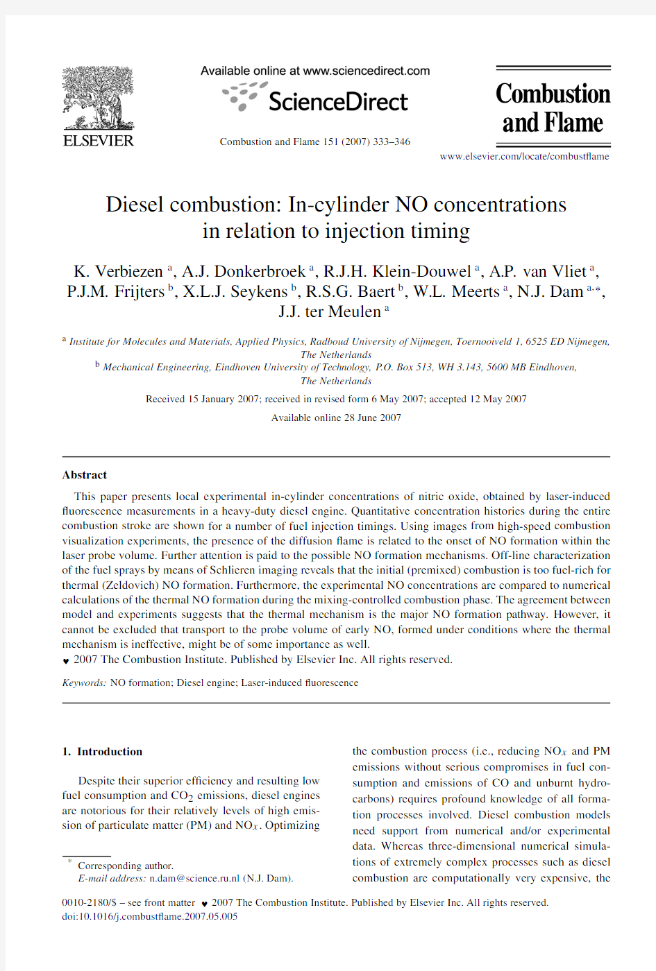
Fig.1.Schematic representation of the engine setup:(a)top view,indicating the ?eld of view of the high-speed camera and the NO LIF probe position;(b)three-dimensional view of the measurement cylinder;(c)23-μs snapshot of the combusting fuel sprays,as recorded by the high-speed camera at 6.3?aTDC (start of injection =8?bTDC);(d)contour plot of the same image,indicating the laser probe location (black dot).The 226-nm laser beam traverses the cylinder almost parallel to its axis.NO ?uorescence is detected by an imaging grating spectrograph (not shown)through the nearest side window.
challenge on the experimental side is to develop reli-able measurement techniques.
Here,we focus on the formation of nitric oxide (NO),presenting quantitative local in-cylinder NO concentration histories as measured by laser-induced ?uorescence (LIF)in a DI diesel engine.Although the LIF technique has often been applied for NO measurements in diesel engines [1–7],the severe at-tenuation of the laser beam and the induced ?uores-cence is not always properly addressed.Exceptions are Stoffels et al.[4],who measured spatially resolved laser beam transmission (although no correction was made for the attenuation of the NO ?uorescence),and Hildenbrand et al.[7],who corrected for the absorp-tion of NO ?uorescence by CO 2(but neglecting addi-tional LIF attenuation caused by,e.g.,soot,and lack-ing a correction for laser beam attenuation).Recently we investigated a number of attenuation correction methods,the combination of which yields a complete picture of all major attenuation processes involved in NO LIF measurements in a diesel engine [8].This de-tailed correction strategy has allowed for the ?rst time a quantitative measurement of the NO concentration in a heavy-duty diesel engine [9].
In this paper,we present in-cylinder NO concen-tration histories for a number of fuel injection tim-ings.Although the effect of injection timing on the exhaust NO concentration is well known,quantitative in-cylinder measurements are scarce.In order to in-terpret our data within the framework of current ideas on diesel spray combustion [10–12],a further charac-terization of the combustion process is indispensable.In a joint effort of research groups in Nijmegen and
Eindhoven,the NO LIF data are complemented by additional experiments including high-speed combus-tion visualization (in the same research engine)and Schlieren imaging of the fuel injection (in a high-pressure cell)and by NO chemistry modeling.
2.Experiment 2.1.The engine
The research engine is a six-cylinder,heavy-duty diesel truck engine.One of its cylinders (hereafter referred to as “measurement cylinder”)is optically ac-cessible via fused silica windows in the piston (“pis-ton window”),in the cylinder wall (“side windows”),and in the cylinder head (“top window”).A slot ma-chined into the piston crown prevents blocking of the detection side window around top dead center (TDC).The measurement cylinder is depicted schematically in Fig.1,and its most relevant speci?cations are com-piled in Table 1.For measurements of the cylinder pressure,the top window can be replaced by a pres-sure transducer (A VL QHC32).An eight-hole fuel in-jector is mounted centrally and can be rotated for easy alignment of the fuel spray with respect to the laser beam probe volume.Fuel injection into the measure-ment cylinder is provided by a home-built common-rail system.The start and end of the injection can be set independently via the electronically actuated injector,each injection yielding 60mg at 1200bar.Fig.2shows the rail pressure during an injection event.During the injection,the pressure varies by
K.Verbiezen et al./Combustion and Flame 151(2007)333–346
335
Table 1
Speci?cations and global operating conditions of the measurement cylinder Engine type Six-cylinder four-stroke DI diesel engine Bore,stroke 130mm,146mm Displacement 1.939L (per cylinder)Compression ratio 15(unmodi?ed:16)
Piston bowl shape “Bathtub”(?at piston window)?piston bowl 84mm Swirl number 1.8
?injector,#holes
0.128mm,8
Fuel injected,inj.pressure 60mg of low-sulfur diesel,1200bar Boost pressure 1.4bar (abs.;no EGR)Engine speed
1430
rpm
Fig.2.Typical injection pressure trace for the engine experiments.For the data shown here,the injector is actuated at 8?bTDC,as is indicated by the arrow.The actual start and end of injection are indicated as well.
~12%.The electronics also allows a double (split)fuel injection (see Appendix A ).The oil-free mea-surement cylinder is skip-?red (1:35)to avoid over-heating;three unmodi?ed cylinders are continuously fueled (by the original line pump)to maintain engine speed.
Measurements were conducted with a rail pressure of 1200bar and at four different fuel injection tim-ings,actuating the fuel injector at 18?,13?,8?,and 3?bTDC (bTDC =before TDC).The effective start of injection (SoI eff )was determined from high-speed imaging (see Section 2.2)and occurs about 3?later;see Table 2for details.Unless explicitly stated oth-erwise,SoI means the nominal start of injection (i.e.actuation of the injection system).The start of com-bustion was retrieved from the cylinder pressure trace and the derived rate of heat release [13],shown in Fig.3.
2.2.High-speed combustion visualization
The combustion process was recorded through the piston window by a high-speed camera (Phantom V7.1,160kHz maximum frame rate);see Fig.1.To visualize the fuel sprays prior to combustion,
Table 2
Operating points of the measurement cylinder a SoI (nominal)?18.0??13.0??8.0??3.0?SoI eff (effective)?14.8??9.3??4.5?0.3?EoI 0.6?6.0?11.1?15.8?SoC ?8.9??5.5?
0.4?4.2?
Inj.duration 15.3?15.3?
15.6?15.5?Ignition delay 5.9?3.8?4.1?3.9?gIMEP (kPa)502±6509±4496±11498±1[NO]exhaust (ppm)
560±112402±80272±55190±38
a All crank angles in ?aTDC (aTDC =after TDC;SoI =
start of injection;EoI =end of injection;SoC =start of combustion).
a continuous-wave argon ion laser beam (Spectra Physics,Stabilite 2016)of circa 5W (operating pri-marily at 488and 517nm)was directed toward a 16-mm-diameter metal sphere located below the pis-ton window,resulting in a highly divergent re?ection illuminating almost the entire combustion chamber.To avoid overexposure of the camera and to suppress the combustion light,a ?lter combination (BG 18and GG 475Schott ?lters)was used,transmitting roughly between 460and 640nm.The camera was synchro-
336K.Verbiezen et al./Combustion and Flame 151(2007)
333–346
Fig.3.Cylinder pressure (top),rate of heat release (middle),and average gas temperature (bottom)for the four injection timings.The nominal start of injection is indicated for each
curve.
Fig.4.The Schlieren imaging setup including the Eindhoven high-pressure,high-temperature cell (EHPC).
nized to the crankshaft of the engine and recorded at one image every 0.3?CA (~35μs),with an exposure time of 23μs,and a resolution of 275μm per pixel.2.3.Fuel spray imaging
The laser elastic scattering measurements merely visualize the liquid phase of the spray (including droplets).Additional off-line experiments involving Schlieren imaging were carried out to image the fuel vapor as well.The Schlieren technique is par-ticularly sensitive to variations in the index of re-fraction,and hence to density gradients,which al-lows a better characterization of the spray geometry.These measurements were performed in the Eind-hoven high-pressure,high-temperature cell (EHPC)using the same injector type and rail pressure as in the engine experiments.A schematic representation of the Schlieren setup is shown in Fig.4.
Vaporizing conditions (30.9bar and 770K)were realized by igniting a combustable mixture 2500ms prior to the fuel injection.After this precombustion,
K.Verbiezen et al./Combustion and Flame151(2007)333–346337
an inert hot gas mixture(N2,CO2,and H2O)with a density of14kg/m3remains.In addition,mul-tiple series of injection events were visualized in a colder(473K)inert ambient gas.Various ambient densities(15–25kg/m3)were studied,covering the range found in the engine tests.These tests further-more showed that the sprays from different nozzle holes were very similar,as was also con?rmed by the high-speed visualization experiments on the test engine.Further details of the EHPC can be found in Refs.[14,15].
For these measurements the same Phantom cam-era was used,operating at60.7kHz,with an exposure time of2μs,and a resolution of430μm per pixel.
2.4.NO LIF measurements
The laser beam for NO excitation traverses the combustion chamber(almost)vertically,30mm away from the injector,and rotated over26?in the swirl di-rection with respect to a fuel spray.The trajectory of the laser beam is shown in Fig.1.The height of the probe volume is limited to the uppermost23mm of the combustion chamber by the size of the detection window.
NO LIF is induced by laser radiation at226.03nm, resonant with the coinciding A2Σ(v =0)←X2Π(v =0)P1(23.5),Q1+P21(14.5),and Q2+ R12(20.5)transitions.This excitation wavelength was suggested by diRosa et al.[17]for high sensitivity and minimal O2LIF interference even at elevated https://www.doczj.com/doc/ee10323580.html,ser radiation(pulses of5–8mJ)is produced by a frequency-mixed dye laser(Radiant Narrowscan D)pumped by a Nd:Y AG laser(Continuum Power-lite Precision II8010).Four vibronic?uorescence bands(at237,248,259,and270nm,corresponding to the A→X(0,1)–(0,4)transitions,respectively)are detected through the nearest side window by an in-tensi?ed CCD camera(Roper Scienti?c,ICCD512T, 5122pixels,16bits)mounted behind a spectrograph (ARC SpectraPro500i,600lines/mm grating).The entrance slit of the spectrograph is parallel to the laser beam direction,and opened to encompass the entire laser beam width for maximum intensity.Two typical raw NO LIF images are shown in Fig.5.
Attenuation effects are minimized(but not negli-gible;see Ref.[16])by keeping the in-cylinder path lengths of laser beam and?uorescence as short as pos-sible(0–23and37mm,respectively).
2.5.NO LIF data processing
In the current analysis,the total NO LIF intensity per vibronic emission band is determined by sum-ming all relevant pixel intensities(areas indicated
by Fig.5.Two single-shot NO LIF images(raw data)recorded through the side window by the spectrograph-camera sys-tem,at8?aTDC(a)and130?aTDC(b).The intensity scales are adjusted individually to show maximum contrast in each image.Start of injection:8?bTDC.
dashed lines in Fig.5b).Consequently,the data repre-sent the average NO density within the probe volume ( 4mm,height23mm).Quanti?cation of the LIF signal requires extensive postprocessing[8,9],which we describe here only brie?y.The importance of tak-ing due care of all factors that affect the experimen-tally obtained signals may be appreciated by realizing that the total conversion factor,from NO LIF data to NO mole fractions,varies by about three orders of magnitude over an engine cycle[9].
2.5.1.Attenuation corrections
We have measured in-cylinder attenuation coef-?cients by means of(1)bidirectional LIF and(2) absorption spectroscopy of CO2and O2.With bidi-rectional LIF,vertical NO LIF intensity pro?les are measured for two opposite directions of the excita-tion laser beam;the spatially resolved laser beam transmission is calculated from the ratio of these pro-?les[18–21].For a single-shot approach,the two counterpropagating laser pulses should be?red quasi-simultaneously.Here,all pulses are?red during dif-ferent cycles,and thus we obtain averaged transmis-sion data.
The attenuation of the NO?uorescence caused by absorption by CO2and O2can be obtained by com-paring each measured NO LIF spectrum to a reference NO LIF spectrum(i.e.,without absorption).The ratio of these spectra yields a relative transmission spec-trum of the NO?uorescence on its way to the detector. Absolute transmission values are obtained by?tting this transmission spectrum,using parameterized CO2
338K.Verbiezen et al./Combustion and Flame151(2007)333–346
[22]and O2[23]absorption cross sections.Due to the strong temperature dependence of the CO2and O2 absorption cross sections,each?t also yields an esti-mate for the local temperature1[24].The additional attenuation of the NO?uorescence by,e.g.,soot is estimated by comparing the calculated CO2and O2 absorption(at226nm)to the(total)laser beam ex-tinction as measured with bidirectional LIF.
We refer to Refs.[8,9]for a more complete de-scription of these techniques and methodology.The above-mentioned technique has the advantage that it is performed simultaneously with the actual NO LIF measurements.Consequently,all measurements were carried out under identical conditions.Transmission curves for the laser beam and the?uorescence are pre-sented in Ref.[16].We apply phase-averaged correc-tion factors to single-shot NO LIF data.The resulting NO concentrations are subsequently phase-averaged over20engine cycles in order to obtain statistics on cycle-to-cycle?uctuations.Error bars in the NO mole fractions presented below include both these cycle-to-cycle?uctuations and the uncertainties in the correc-tion factors.
2.5.2.Pressure and temperature dependence
We have used LIFSim[25]to calculate the pres-sure and temperature dependence of the NO LIF in-tensity.Although the gas composition may have a large in?uence on the quenching rates and thus on the absolute LIF intensity,here we are only interested in the relative changes of the LIF signal(absolute val-ues are obtained by calibration,see next paragraph). We have demonstrated previously that the exact gas composition is of minor importance[9],and all LIF-Sim calculations were performed for constant([O2]: [N2]=1:4)composition of the in-cylinder gases.Fur-ther input parameters were the cylinder pressure and the local temperature.The latter was estimated from the observed CO2and O2absorption spectra(previ-ous paragraph).
2.5.
3.Calibration
After correcting the NO LIF data for attenuation effects and the pressure and temperature dependence of the?uorescence yield,the processed data are multi-plied by a calibration factor that scales the in-cylinder concentration at the end of the stroke(the exhaust valve opens at130?aTDC)to the exhaust NO con-centration.The latter is determined by a commercial exhaust gas analyser(SIGNAL Instruments,NOX an-alyzer series4000),sampling the exhaust of only the 1In fact,the?tted temperature is a weighted average of the temperature pro?le along the trajectory of the NO?uores-cence.This effective temperature is expected to be strongly biased to the probe volume temperature[9]
.Fig.6.Schematic representation of the combustion zones (numbered1–4).The?ame front is represented by solid lines;dashed lines indicate the spray axes;the position of the NO excitation laser beam is indicated by the black dot. measurement cylinder.Its reading is scaled by the skip-?re ratio and an additional factor accounting for the fact that the sampling occurs nonisokinetically (see Appendix B).We assume homogeneous phase-averaged NO distributions at130?aTDC.
2.6.NO formation calculations
The thermal NO formation has been calculated us-ing the extended Zeldovich mechanism.For the cal-culations,the combustion event is divided into steps of1?CA,during which a certain amount of fuel is burnt.This divides the?ame spatially into zones[26, 27].Each zone starts in the volume traversed by the ?ame front during the corresponding step of1?.Sub-sequently,the zone moves outward as new zones are formed at the?ame front during the following crank angle steps.This is shown schematically in Fig.6. The calculations are based on the assumption that no mixing occurs between different zones;entrain-ment of fresh air into a zone,however,is modeled based on our spray visualization data that are used as input for the spray model by Naber and Siebers [10].A chemical equilibrium solver(without N chem-istry)[28]is used to calculate the composition of the combustion products and the corresponding adiabatic ?ame temperature.The latter is then used to calculate the thermally formed(Zeldovich)NO per zone.These calculations are detailed below.
The amount of fuel burnt in each zone(i.e.dur-ing1?)is determined from the rate of heat release (Fig.3).Only the mixing-controlled part of the com-bustion is considered(the premixed combustion is too fuel-rich for signi?cant thermal NO formation,as will be discussed in Section3.2).It is assumed that the combustion in each zone starts under stoichiometric conditions,which is a reasonable assumption for the diffusion?ame.For each zone,the initial composition is now known.Its temperature is taken equal to the un-burnt mixture temperature(derived from the pressure curve of the motored engine,without fuel injection), and is used as an input to a chemical equilibrium
K.Verbiezen et al./Combustion and Flame 151(2007)333–346
339
Fig.7.Single frame from a high-speed Schlieren movie of a single fuel injection into the EHPC,at 770K and 30.9bar.The white contour guides the eye.
solver to determine the composition of the combus-tion products and the corresponding adiabatic ?ame temperature.Species considered are O 2,N 2,CO 2,H 2O,CO,H 2,OH,O,N,and H.In all zones,the pressure is equal to the measured in-cylinder pressure (Fig.3).
With the adiabatic ?ame temperature and the O,O 2,N,OH,and H concentrations the NO formation rate is calculated by means of the extended Zeldovich mechanism.The main equations are
(1)d [N ]
dt ≈0,(2)d [NO ]
dt
=2k 1,r [O ][N 2]?2k 1,l [NO ][N ].The reaction rate constants k are taken from GRI 2.11[29].The zone temperature is initially equal to the adiabatic ?ame temperature,but it quickly decreases due to mixing with colder unburnt air and due to ex-pansion of the cylinder volume.The resulting shift in the chemical equilibrium,in?uencing the NO forma-tion rate,is included in the calculations.The computa-tion of NO formation is stopped when the temperature of the zone drops below 1700K,which is often used as a cutoff temperature for thermal NO formation.
3.Results and discussion 3.1.Engine characteristics
Table 2summarizes the operating points that were used in this study.The effective start and end of in-jection were determined from the combustion movies measured in the engine.The start of combustion has been derived from the heat release curves in Fig.3.The exhaust NO concentration levels are indicated as well.
3.2.Fuel spray characterization
Time-resolved (vapor)spray penetration was mea-sured in the EHPC by means of high-speed Schlieren
imaging.A typical frame taken from the high-speed movie is shown in Fig.7.The strong background den-sity ?uctuations are a consequence of the precombus-tion.They move much more slowly than the fuel jet,and in the analysis they are dealt with by interpolat-ing the spray edge across each “dark spot,”in order to obtain a reliable measure for the spray angle and penetration depth.Based on these results,the aver-age spray full angle was evaluated as θspray =18?.Following the approach by Naber and Siebers,for a given spray angle,the measured penetration length can be correlated with the average equivalence ratio (mass-averaged value across the spray cross-sectional area)at the spray tip [10].For a quasi-steady spray this penetration curve also corresponds to the depen-dence of this average equivalence ratio on the distance to the injector.Both the spray penetration and the cor-responding equivalence ratio are shown in Fig.8for the four injection timings we investigated.For each curve the start of combustion is indicated as well,re-vealing that on average the jet is rather fuel-rich when the mixture ignites:Φ≈1.5for all curves except the one for 18?bTDC when Φ≈1.2.
The relatively high equivalence ratios at the start of combustion suggest that the initial,premixed com-bustion is too fuel-rich for signi?cant thermal NO formation to take place,as the latter requires near-stoichiometric equivalence ratios (0.8 Φ 1.0)[30].Prompt NO formation,however,may occur in rich zones with equivalence ratios up to Φ≈1.8and may play some role in the observed NO concentra-tions.
Fig.8also indicates that the combustion starts with the spray tip close to the piston bowl rim.For the injection at 18?bTDC,the jet has just reached the bowl rim when ignition occurs,whereas for the other injection timings,the spray tip is still 6–7mm away from the rim.This is in agreement with the high-speed combustion movies showing the ?rst combustion lu-minosity (i.e.,soot incandescence)at the edges of the piston window.
340K.Verbiezen et al./Combustion and Flame 151(2007)
333–346
Fig.8.Relation between spray penetration and crank angle,and equivalence ratio as a function spray tip location.The start of injection is indicated in each penetration curve,as well as the piston bowl diameter.
3.3.NO LIF measurements
The in-cylinder NO concentrations are shown in Fig.9as a function of crank angle and injection timing.The data points are phase-averaged over 20cycles,and the error bars include both the process-ing uncertainties and cycle-to-cycle ?uctuations.Sim-ilarly to the exhaust concentration,the in-cylinder NO concentration increases almost linearly when the fuel injection is advanced.All NO curves have very similar shapes,varying only in the moment of ?rst NO and in amplitude.The peak concentrations range from 1500ppm (SoI =3?bTDC)to values just over 5000ppm (SoI =18?bTDC).Typically,the peak concentration is approximately nine times higher than the asymptotic value reached by 130?aTDC.
Generally,the ?rst signi?cant NO LIF appears ~5?after the start of combustion.Given the facts that (1)the initial,premixed combustion takes place within the fuel spray boundaries [11]and that (2)the laser beam is 14mm away from the spray axis,the probe location may be too far away to detect any (prompt)NO formed during the initial premixed combustion,unless this prompt NO is convected to-wards the probe location.Such transport cannot be excluded;with a swirl ratio of 1.8this would require 5?–7?,which is only slightly longer than the observed delay of 5?.Nevertheless,in the latter case a consid-erable dilution of the transported NO would be ex-pected.
On the other hand,the high-speed combustion movies show that the moment when the ?rst NO is detected coincides within 0.5?CA with the moment when luminous soot 2is ?rst observed at the probe
2According to Dec’s conceptual model,the luminous soot
is representative of the diffusion ?ame [11]
.
Fig.9.Local NO mole fractions (phase-averaged over 20cycles)as a function crank angle and injection timing.The error bars contain cyclic variations (10–30%)as well as the uncertainties in all processing steps (attenuation correction and p ,T dependence).The solid curves are explained in Section 3.4.
location.This is shown in Fig.10.The ?rst appear-ance of the diffusion ?ame in the probe volume is also indicated in Fig.9.This implies that the observed
K.Verbiezen et al./Combustion and Flame 151(2007)333–346
341
Fig.10.The moment of ?rst detected NO vs the moment of ?rst soot luminosity in the probe volume.The straight line assumes equal moments of ?rst NO LIF and ?rst soot
luminosity.
Fig.11.Local temperatures,based on CO 2and O 2absorption spectra.The spatially averaged gas temperature (derived from the pressure curve)is shown for comparison.
NO is (primarily)due to the thermal NO formation mechanism;the arrival of the diffusion ?ame at the probe location quickly raises the local temperature above the threshold for thermal NO formation (1700–1800K),leading to a sudden increase of the NO con-centration,in agreement with the NO LIF results.The sudden temperature increase is con?rmed by experi-mental temperature values derived from CO 2absorp-tion spectra,shown in Fig.11.Note that the measured peak temperatures do not vary signi?cantly with SoI,in contrast to the peak NO concentrations of Fig.9.
From 40?aTDC onwards,all NO concentration curves decay at the same rate.This is illustrated in Fig.12,where all curves are normalized at 130?aTDC.By 40?aTDC the combustion has ceased for all four injection timings.Moreover,the local temper-ature has dropped below 1800K,and no signi?cant NO formation is to be expected.As a consequence,the concentration decay is attributed to mixing of the combustion products with unburnt gases until a stable value is reached.This process is identical for all four experimental conditions.
342K.Verbiezen et al./Combustion and Flame 151(2007)
333–346
Fig.12.Normalized NO mole fractions during the combustion stroke,based on the data in Fig.9
.
Fig.13.Calculated and experimental exhaust NO concentration vs SoI.
3.4.Calculated NO formation
Fig.13demonstrates that the NO formation calcu-lations are in reasonable agreement with the exhaust concentration measurements.Fig.14shows the cal-culated NO molar fraction in all product zones as a function of crank angle.The ?rst zone is formed when the premixed burn spike of the heat release rate has its maximum,which is a crude estimate of the onset of the diffusion ?ame (according to the com-bustion movies,the luminous diffusion ?ame appears even 1?–2?CA earlier).Every following 1.0?,a new product zone is formed.The observed decrease in the NO concentration per zone is caused by (1)a shifting of the H–C–O equilibrium as a result of the varying temperature and leading to destruction of some of the earlier formed NO and (2)by diluting the zone with newly entrained fresh air.
For all four data sets,the start of the ?rst zone is very close to the moment the diffusion ?ame ap-pears in the laser probe volume.For instance,for the SoI =18?bTDC measurements,the ?rst zone starts at 3.5?bTDC,as compared to 3.9?bTDC for the ap-pearance of the ?ame;for the SoI =8?bTDC series these values are both 4.5?aTDC.Therefore,in line with the earlier observations (Section 3.3),the ?rst zones are considered representative for the initial part of the experimental concentration curve.In reality,of course,the probe volume will see a mixture of such zones.
For SoI =18?bTDC,a peak concentration around 3600ppm is calculated,in reasonable agreement with the experimental 5100±1700ppm.The agreement between experiment and calculation is of similar qual-ity for the other injection timings.Here it should be noted that the model does not contain any adjustable parameters,but just calculates the expected amount of NO on the basis of the measured rate of heat release and spray characteristics.The calculated NO concen-tration of the ?rst zone is also shown in Fig.9for easy comparison of the peak values.The difference in the decay rate between experimental and numer-ical concentration histories might be related to the fact that the zones move past the probe volume,so that the ?rst zone is only representative for the ini-tial part of the measured concentration history.An-other explanation might be the air entrainment model:the model by Naber and Siebers is only applica-ble to a quasi-steady spray and will only be an ap-
K.Verbiezen et al./Combustion and Flame151(2007)333–346
343
Fig.14.NO concentration in each product zone vs crank angle.
proximation of the mixing processes in the diffusion ?ame.
The calculations show that once the diffusion ?ame has arrived at the probe volume,local ther-mal NO formation is fast enough to account for a signi?cant fraction of the observed NO.Since the observed NO concentrations are nevertheless system-atically higher than the calculated ones,it cannot be excluded that transport of earlier formed NO(not modeled)might play a role as well.
4.Summary and conclusions
We have presented local in-cylinder NO concen-tration histories,both measured and calculated,for various injection timings in a diesel engine.Based on a combination of these data with additional ex-periments,such as high-speed visualization of the combustion and Schlieren imaging of the fuel spray, we feel it justi?ed to draw the following conclu-sions.
The well-known trend of increasing exhaust NO emissions with advancing injection timing is also re-?ected in the in-cylinder concentration histories.In fact,all concentration histories are quite similar,vary-ing only in onset and peak amplitude.In each case, the maximum concentration in the probe volume is around nine times the concentration reached by the end of the stroke.Apparently,only a small part of the combustion chamber is responsible for the bulk of the NO that is produced.This is of course in line with the engine operating at low load during the experi-ments,resulting in a low overall equivalence ratio.
The same NO vs SoI trend is observed in our numerical data.The agreement between experiment and calculation is qualitatively good.This suggests that the observed NO is caused by local thermal NO formation rather than transport.However,the exper-imental values are systematically somewhat higher than the calculated ones.Therefore,it cannot be ex-cluded that NO formed during the premixed combus-tion is transported towards the probe location.The time needed for this transport is very close to the ob-served delay between the start of combustion and the ?rst NO LIF appearance,suggesting that the prompt and/or N2O mechanisms may indeed contribute to the observed local NO concentrations.
344K.Verbiezen et al./Combustion and Flame 151(2007)
333–346
Fig.15.Rate of heat release for a single (SoI =18?bTDC)and a split fuel injection (SoI 1=18?bTDC,SoI 2=8?bTDC).
Our present experimental data do not allow an ac-curate investigation of the prompt NO mechanism.The data in Fig.8show that the initial combustion is too fuel-rich for signi?cant thermal NO formation.Therefore,further in-cylinder NO LIF experiments,moving the probe volume toward the premixed burn region and combined with more accurate local tem-perature measurements (e.g.,by vibrational thermom-etry [31]),would be elucidating.Thus far,measure-ments with the laser beam directed through a fuel spray suffered from severe window fouling,and the current probe location was preferred for further exper-iments.Previous “through spray”NO LIF measure-ments in the same research engine,[9]but with the original cam-driven fuel injection,showed signi?cant NO ?uorescence during the premixed burn phase,at temperatures too low for thermal NO formation.
All concentration curves decay at the same rate from 40?aTDC onwards.This is attributed to trans-port/mixing,since by that time the combustion has ?nished and local temperatures are too low for signif-icant thermal NO formation.This is also con?rmed by the calculations,that show a constant NO mass af-ter 40?aTDC.Considering the large impact of trans-port on the local NO concentration,a more detailed comparison of experimental and numerical data will only be possible either by (1)by extending the ?uid dynamics of the numerical simulations,or (2)by two-dimensional LIF imaging of a larger fraction of the combustion chamber,measuring the total NO density [3].The latter would require two-dimensional attenu-ation corrections as well as a local temperature map,two issues that will bring new experimental chal-lenges.
Acknowledgment
This research is supported by the Technology Foundation STW,applied science division of NWO and the technology programme of the Dutch Ministry of Economic Affairs.
Appendix A.Split fuel injection
In addition to the four injection strategies,the ef-fect of split fuel injection was investigated as well.For the latter,30mg of fuel was injected twice,at 18?bTDC and at 8?bTDC,leaving ~5?between the two injections.
Fig.15shows that the maximum rate of heat re-lease is signi?cantly reduced by the split injection.Due to the increased entrainment of fresh air,and due to cooling by the late second injection,the combus-tion temperatures are lower,and as a result the ther-mal NO formation is reduced.This was also observed experimentally,the exhaust NO concentration being reduced from 560ppm (single injection at 18?bTDC)to 412±80ppm.The in-cylinder concentrations are shown in Fig.16.The concentration history for the single injection at 18?bTDC is shown for compari-son.
Interestingly,the peak concentration is only ~5times higher than the ?nal concentration,as opposed to the factor of 9for the single injections.This is most likely a consequence of the improved air entrain-ment (during combustion),lowering the peak tem-peratures and diluting the combustion products.Af-ter 40?aTDC,when the combustion has ended,the concentration history follows the same decay as the histories for the single injections.
Appendix B.Exhaust calibration in skip-?red operation
The time response of the exhaust gas analyzer,used for calibration of the in-cylinder NO measure-ments,is insuf?cient to resolve the NO concentration levels of every individual engine cycle.Thus,only averages can be obtained.By skip-?ring the measure-ment cylinder (at a ratio of 1:35),the exhaust gas of a ?red cycle is strongly diluted,with the com-pressed air resulting from adjacent motored cycles.If the exhaust gas were measured isokinetically (i.e.,
K.Verbiezen et al./Combustion and Flame 151(2007)333–346
345
Fig.16.Local NO mole fractions during the combustion stroke,for single and split injections.The start of each injection is indicated in the upper right
corner.
Fig.17.Measured exhaust NO concentration [32]as a function of the number of ?red cycles per 35.The dashed straight line assumes a linear dependence;the curved solid line is based on a bias of ξ=2.
equal sampling speed for all cycles),the NO concen-tration from a ?red cycle would simply be 35times as high as the average concentration.In practice,it was observed that the hot exhaust from ?red cycles is sampled more easily,thus biasing the average con-centration.This is demonstrated in Fig.17,showing a sublinear dependence of the analyzer reading as a function of ?red cycles per 35.The ?t is given by the equation (B.1)
[NO ]meas (n f )=
ξn f [NO ]actual
n m f
,
with [NO ]meas the measured NO concentration,[NO ]actual the actual NO concentration from a ?red cycle,n f and n m the number of ?red and motored cycles,respectively,and ξthe “bias”towards a ?red cycle.The best ?t is obtained with ξ≈2,indicating that a skip-?red exhaust measurement overestimates the NO concentration from a ?red cycle by approxi-mately a factor of two.Obviously,for n f =35(and n m =0),one would directly measure the NO con-centration of a ?red cycle.In general,the higher n f ,the more accurate the value of ξ.In practice,n f is re-
stricted to low values in order to prevent damage to the nonlubricated measurement cylinder.
References
[1]Th.M.Brugman,R.Klein-Douwel,G.Huigen,E.van
Walwijk,J.J.ter Meulen,Appl.Phys.B 57(1993)405–410.
[2]Th.M.Brugman,G.G.M.Stoffels,N.J.Dam,W.L.
Meerts,J.J.ter Meulen,Appl.Phys.B 64(1997)717–724.
[3]J.E.Dec,R.E.Canaan,SAE Tech.Pap.Series,no.
980147,1998.
[4]G.G.M.Stoffels,E.J.van den Boom,C.M.I.Spaan-jaars,N.Dam,W.L.Meerts,J.J.ter Meulen,J.C.L.Duff,D.J.Rickeard,SAE Tech.Pap.Series,no.1999-01-1487,1999.
[5]F.Hildenbrand,C.Schulz,J.Wolfrum,F.Keller,E.
Wagner,https://www.doczj.com/doc/ee10323580.html,bust.Inst.28(2000)1137–1143.[6]E.J.van den Boom,P.B.Monkhouse,C.M.I.Spaan-jaars,W.L.Meerts,N.J.Dam,J.J.ter Meulen,in:V .I.Vlad (Ed.),ROMOPTO 2000,Sixth Conference on Op-tics,Proc.SPIE,vol.4430,2001,pp.593–606.
346K.Verbiezen et al./Combustion and Flame151(2007)333–346
[7]F.Hildenbrand,C.Schulz,F.Keller,G.K?nig,E.Wag-
ner,SAE Tech.Pap.Series,no.2001-01-3500,2001.
[8]K.Verbiezen,R.J.H.Klein-Douwel,A.J.Donkerbroek,
A.P.van Vliet,W.L.Meerts,N.J.Dam,J.J.ter Meulen,
Appl.Phys.B83(2006)155–166.
[9]K.Verbiezen,R.J.H.Klein-Douwel,A.P.van Vliet,
W.L.Meerts,N.J.Dam,J.J.ter Meulen,https://www.doczj.com/doc/ee10323580.html,bust.
Inst.31(2006)765–773.
[10]J.D.Naber, D.L.Siebers,SAE Tech.Pap.Series,
no.960034,1996.
[11]J.E.Dec,SAE Tech.Pap.Series,no.970873,1997.
[12]P.F.Flynn,R.P.Durrett,G.L.Hunter,A.O.zur Loye,
O.C.Akinyemi,J.E.Dec,C.K.Westbrook,SAE Tech.
Pap.Series,no.1999-01-0509,1999.
[13]J.B.Heywood,Internal Combustion Engine Funda-
mentals,McGraw–Hill,Singapore,1988.
[14]R.J.H.Klein-Douwel,M.Douch,L.M.T.Somers,W.A.
de Boer,R.S.G.Baert,Proc.European Combustion Meeting,Orléans,France,2003.
[15]P.J.M.Frijters,R.J.H.Klein-Douwel,S.S.Manski,
L.M.T.Somers,R.S.G.Baert,Proc.European Combus-tion Meeting,Louvain-la-Neuve,Belgium,2005. [16]K.Verbiezen,Quantitative NO measurements in a
diesel engine,Ph.D.thesis,Radboud University,Ni-jmegen,The Netherlands,2007,available from http:// webdoc.ubn.ru.nl/mono/v/verbiezen_k/quannomei.pdf.
[17]M.D.diRosa,K.G.Klavuhn,R.K.Hanson,Combust.
Sci.Technol.118(1996)257–283.
[18]D.Stepowski,https://www.doczj.com/doc/ee10323580.html,bust.Inst.23(1990)1839–
1846.
[19]M.Versluis,N.Georgiev,L.Martinsson,M.Aldén,
S.Kr?ll,Appl.Phys.B65(1997)411–417.
[20]G.G.M.Stoffels,S.Stoks,N.Dam,J.J.ter Meulen,
Appl.Opt.39(2000)5547–5559.[21]V.Sick,B.D.Stojkovic,Appl.Opt.40(2001)2435–
2442.
[22]C.Schulz,J.B.Jeffries,D.F.Davidson,J.D.Koch,R.K.
Hanson,https://www.doczj.com/doc/ee10323580.html,bust.Inst.29(2002)2735–2742.
[23]K.Verbiezen,A.P.van Vliet,W.L.Meerts,N.J.Dam,
J.J.ter Meulen,Combust.Flame144(2006)638–641.
[24]J.B.Jeffries,C.Schulz,D.W.Mattison,M.A.Oehl-
schlaeger,W.G.Bessler,T.Lee, D.F.Davidson, R.K.Hanson,https://www.doczj.com/doc/ee10323580.html,bust.Inst.30(2005)1591–1599.
[25]W.G.Bessler,C.Schulz,V.Sick,J.W.Daily,LIFSim:
A versatile modeling tool for nitric oxide LIF spectra,
Chicago,2003,https://www.doczj.com/doc/ee10323580.html,.
[26]S.L.Plee,J.P.Ahmad,J.P.Myers,G.M.Faeth,Proc.
Combust.Symp.19(1982)1495–1502.
[27]K.J.Wu,R.C.Peterson,SAE Techn.Pap.Series,
no.861566,1986.
[28]S.Gordon,B.J.McBridge,Computer program for the
calculation of complex chemical equilibrium composi-tions with applications;I.Analysis,NASA Reference Publication1311,1994.
[29]G.P.Smith,D.M.Golden,M.Frenklach,N.W.Mori-
arty,B.Eiteneer,M.Goldenberg,C.T.Bowman,R.K.
Hanson,S.Song,W.C.Gardiner Jr.,V.V.Lissian-ski,Z.Qin,GRI mech2.11,Technical report,2000;
https://www.doczj.com/doc/ee10323580.html,/gri_mech.
[30]https://www.doczj.com/doc/ee10323580.html,ler,C.T.Bowman,Prog.Energy Combust.
Sci.15(1989)287–338.
[31]W.G.Bessler,F.Hildenbrand,C.Schulz,Appl.Opt.40
(2001)748–756.
[32]G.J.Schoonderbeek,Emissiemeting aan de uitlaat van
een dieselmotor,Graduation report,University of Ni-jmegen,2002.
自动螺丝机说明书 Document number:WTWYT-WYWY-BTGTT-YTTYU-2018GT
自动锁螺丝机 (SCREW-160/180II/320 ) 目录 一、自动锁螺丝机功能简介 (01) 二、主画面概要 (01) 三、主界面功能介绍 (02) 四、参数设置界面介绍··················-03~04- 五、螺丝规格界面介绍 (05) 六、教导(模拟手柄)界面介绍 (06) 七、步骤镜像界面介绍 (07) 八、参数复制界面介绍 (08) 九、其他设置界面介绍 (09) 十、坐标校正界面介绍 (10) 十一、文件管理界面介绍 (11) 十二、产量报表界面介绍 (12) 十三、USB复制界面介绍 (13) 十四、螺丝供给器和电批调节 (14) 十五、程序制作简易流程 (15) 十六、故障排除 (16)
十七、维护与保养 (17) 十八、技术参数 (17) 十九、售后服务 (18) 二十、注意事项 (18) 二十一、易损伤配件表···················-19~22- 一、自动锁螺丝机功能简介 1.全中文界面,动态显示运行状态,直观可见的参数 2.密码保护功能、保护系统参数不被随意更改 3.程序之间有阵列复制、参数复制功能 4.程序具有坐标部分校正、整体校正功能、节省手动调试程序的时间 5.具备插入、手动输入坐标、删除功能、方便快速修改及制作程序 6.单步自动定位功能,极大的方便程序的制作确认及坐标修复等 7.大容量储存数据程序使用时可随意切换调用 8.自动防呆感应、流水式作业平台高效、节省人工、节约成本 二、主要面概要 人机界面由以下供13界面组成: 1.主界面 2.参数设置 3.螺丝规格 4.教导 5.步骤镜像 6.参数复制
各种花卉的英文名 iris蝴蝶花 cockscomb鸡冠花 honeysuckle金银花chrysanthemum菊花 carnation康乃馨 orchid兰花 canna美人蕉 jasmine茉莉花 daffodil水仙花 peony牡丹 begonia秋海棠 cactus仙人掌 christmas flower圣诞花/一品红poppy罂粟 tulip郁金香 chinese rose月季 violet紫罗兰 peach flower桃花 aloe芦荟 mimosa含羞草 dandelion蒲公英
plum bolssom梅花中国水仙 new year lily 石榴 pomegranate 月桂victor's laurel 报春花 polyanthus 木棉 cotton tree 紫丁香 lilac 吊钟 lady's eardrops 紫荆 Chinese redbud 百合 lily 紫罗兰 wall flower 桃花 peach 紫藤 wisteria 杜鹃 azalea 铃兰 lily-of-the-valley 牡丹 tree peony 银杏 ginkgo 芍药 peony 蝴蝶兰 moth orchid 辛夷 violet magnolia 蟹爪仙人掌 Christmas cactus 玫瑰 rose 郁金香 tulip
茶花 common camellia 千日红 common globe-amaranth 非洲堇 African violet 栀子花 cape jasmine 木槿 rose of Sharon 风信子 hyacinth 百子莲 African lily 牵牛花 morning glory 君子兰 kefir lily 荷包花 lady's pocketbook 含笑花 banana shrub 非洲菊 African daisy 含羞草 sensitive plant 茉莉 Arabian jasmine 猪笼草 pitcher plant 凌霄花 creeper 树兰 orchid tree 康乃馨coronation 鸡冠花 cockscomb 荷花lotus 鸢萝 cypress vine 菩提 botree
自动打螺丝机是通过各类电动、气动元器件实现螺丝的自动输送、拧紧、检测等工序,通过设备来简化螺丝紧固工序,达到减少人工数量及减少人工误操作带来的不良因素。是一种典型的非标自动化设备。 自动锁螺丝机主要分为:手持式锁螺丝机、多轴式自动锁螺丝机、坐标式自动锁螺丝机。 自动锁螺丝机主要应用于M1-M8螺丝的锁付。由于其属于非标自动化设备,具有可定制的特性,涉及螺丝紧固的产品都能获得相应的解决方案,应用领域较为广泛。 一、工作基本原理 家电自动打螺丝机是通过各类电动气动元器件实现螺丝的自动输送、拧紧、检测等工序,通过设备来简化螺丝紧固工序,达到减少人工数量及减少人工误操作带来的不良因素。是一种典型的非标自动化设备。 自动送钉机 自动送钉机主要负责螺丝的筛选、排列、检测、分料、输送等工序,是替代人工取螺丝的重要环节。 锁付机构 锁付机构通过配置的电批、风批或伺服电机,按照程序设定来执行拧螺丝动作,彻底替代人工作业。 二、自动打螺丝机的分类
多轴式:多轴同时拧螺丝,一次可拧好产品所有螺丝,效率较高; 坐标式:通过程序设定的坐标点位来逐个(或多个)拧螺丝,可储存编辑多套方案,适用范围广; 手持式:手持式同样配有自动送钉机,由人工找螺丝孔位拧螺丝,可锁付产品任何部位螺丝,灵活性较好。 三、自动打螺丝机使用方法 自动锁螺丝机的使用相对比较简单,简单的说就是员工放置产品即可,设备自动执行送螺丝、拧螺丝、检测等工序。一般有以下步骤:1:检查通气通电情况,打开电源开关和通气阀; 2:检查所有零部件驱动行程,坐标式还需要预先对不同的产品进行编程控制设定锁付路径; 3:放入待拧螺丝的产品,进行逐个流程的点动或寸动,从而达到检视所有工作的准确性和行程的到位; 4:开机试运行,并检查成品的效果,质量,但一切进入稳定后,方可放心使用生产; 5:定期进行质量检查,性能判定; 四、家电自动打螺丝机保养维修
n o i t a r e n e g r e w o P r e w o P
Contents MAN diesel engines for power generation . . . . . . . . . . . . . . . . . . . . . . . . . . . . . . . . . . . . . 3 Servicing concept . . . . . . . . . . . . . . . . . . . . . . . . . . . . . . . . . . . . . . . . . . . . . . . . . . . . . . . . 3 Application type and product range . . . . . . . . . . . . . . . . . . . . . . . . . . . . . . . . . . . . . . . . . . 4 Description of engines D2866 (6) D2876 (8) D2676 (10) D2848 (12) D2840 (14) D2842 (17) D2862 (20)
MAN diesel engines for power generation Power wherever needed MAN offers manufacturers of power generators all over the world a broad spectrum of 6-, 8-, 10- and 12-cylinder engines including radiators for peak load leveling as well as for supplying emergency power and base loads. Depending on their type of operation in PRP (Prime Power), ESP (Emergency Standby Power), COP (Continuous Power) or LTP (Limited Time Power), the engines can be run for a maximum of between 200 and 8?000 hours a year. Totally reliable and with dependable availability and exemplary economy, they provide limitless energy generation. Transforming night into day. Customer Benefits n n MAN is a strong and independent partner for packagers and offers high quality engines made in Germany n n Global after sales network guarentees short-term spare parts supply n n Eco-friendly operation as a result of lower con-sumption of fuel and lubricating oil n n MAN engines with high efficiency, reliability and low maintenace costs result in profitable prime power operation especially in emerging markets n n MAN engines for standby operation to pro-vide maximum power output with quick load a cceptance in case of power shortage n n Ideal balance between compact design and r obust construction allows smaller size of c ontainer gensets with high durability Servicing concept MAN offers power-unit manufacturers a tailor-made servicing concept. This is how MAN gives you the option of performing servicing for your end customers yourself, from start to finish. This is made possible by an extensive training offering which can be matched individually to your needs. Power – Diesel engines for power generation 3
植物花卉中英文对照、花卉英文名大全 金橘--------------kumquat 米仔兰(米兰)--------- milan tree 变叶木-------------croton 一品红-------------poinsettia 扶桑--------------Chinese hibiscus 吊灯花-------------fringed hibiscus 马拉巴栗(发财树)------- Guiana chestnut 山茶--------------camellia 云南山茶------------Yunnan camellia 金花茶-------------golden camellia 瑞香--------------daphne 结香--------------paper bush 倒挂金钟------------fuchsia 八角金盘------------Japan fatsia 常春藤-------------ivy 鹅掌柴-------------umbrella tree 杜鹃花-------------rhododendron 茉莉花-------------jasmine 桂花--------------sweet osmanthus 夹竹桃-------------sweet-scented oleander 黄花夹竹桃-----------lucky-nut-thevetia 鸡蛋花-------------frangipani 龙吐珠-------------bleeding-heart glorybower 夜香树(木本夜来香)------night jasmine 鸳鸯茉莉------------broadleaf raintree 栀子花-------------cape jasmine 蝴蝶兰-------------moth orchid 卡特兰-------------cattleya 石斛--------------dendrobium 兜兰--------------lady slipper 兰花--------------orchid 春兰--------------goering cymbidium
楷徽自动锁螺丝机操作规程 一、自动锁螺丝机操作规程 1、开启电源,接通气源,调节好扭力和气压; 2、将螺丝倒入螺丝料仓内,螺丝量以不超过螺丝输送轨道高度为宜; 3、检查拨码开关是否对应产品型号; 4、第一次索螺丝前,需检查电批夹嘴内是否有一粒螺丝待锁; 5、如无一粒螺丝在电批夹嘴上待锁,需按测试按钮,使机器运动两次,保证电批夹嘴上有一粒螺丝在电批夹嘴上待锁; 6、检查供料机振动器调整开关是否在指定的位置上; 7、检查完毕,按复位开关,开始生产。 二、自动锁螺丝机操作规定 使用设备安全最重要,操作先进自动化设备没有规范和管理,且不能发挥它带来的效益,自动螺丝机也是一种。虽然自动锁螺丝机安全系数没那么严禁,但正常使用发挥其基本功能,更多的节省时间,提高生产效率,所以对自动锁螺丝机使用及维修管理说明还是有必要知道的。 1、严格执行以岗位责任制、安全操作规程、常规检查、维修保养等安全使用和运营的管理制度。 2、使用操作人员必须经过相应的安全技术培训。 3、制定自动锁螺丝机安全技术性能定期检验制度,根据自动锁螺丝机的安全性能和技术参数,对自动锁螺丝机定期检验,确保自动锁螺丝机运行过程的安全。 4、自动锁螺丝机的使用人员,负责自动锁螺丝机的日常检查和保养,并做好日常的检查保养记录。 5、针对自动锁螺丝机的使用性质制定交接班制度。分班轮换使用或集体使用的自动锁螺丝机,由当班负责人全面负责。 6、大型精密气动工具要严格实行定人、定机的管理办法。 7、对特种自动锁螺丝机严格按照国家有关规定,实行持证上岗。 8、自动锁螺丝机必须严格按照使用说明和安装技术规程的要求进行安装、调试后使用。
产品安全数据表(MSDS) 第一部分化学品及企业标识__________________________________________________________________________________________________________________________________________________ 化学品中文名称:DIESEL ENGINE OIL CF 15W-40柴油发动机油 化学品俗名或商品名:柴油机油 化学品英文名称:DIESEL ENGINE OIL CF 15W-40 企业名称:天津日石润滑油脂有限公司 地址:天津市滨海新区汉沽化工街5号 邮编:300480 电子地址邮件: 传真号码:(086) 022 — 67161104 或 67161107 企业应急电话:(086) 022 — 67161105 或 67161106 技术说明书编码:无 生效日期:2009年2月 国家应急电话:无 第二部分成分/组成信息 主要组成:润滑油:81%、添加齐IJ:19% 化学品名称:石油系润滑油和添加剂 外观:黄褐色透明液体___________________________________________________________________ 第三部分危险性概述 危险性类别:非危险品。 燃爆危险:无爆炸危险性,属可燃物品。 第四部分急救措施 皮肤接触:用肥皂水及清水彻底冲洗皮肤。 眼睛接触:立即用流动清水或生理盐水冲洗,严重情况下就医。 吸入:迅速脱离现场至空气新鲜处。保持呼吸道通畅。必要时就医。 食入:清理口腔遗留物,吐出饮入物,必要时就医。 第五部分消防措施— 危险特性:遇明火、高热能引起燃烧。 燃烧产物:CO、CO2 灭火方法及灭火剂:可用泡沫、二氧化碳、干粉、砂土扑救,用水灭火无效。_________________ 第六部分泄露应急处理 应急处理:切断火源。迅速撤离泄露污染区人员至安全地带,并进行隔离,严格限制出入。建议应急处理人员戴自给正压式呼吸器,穿防毒服。尽可能切断泄露源。防止进入下水道、排洪沟等限制性空间。小量泄露:尽可能将溢漏液收集在密闭容器内,用砂土、活性碳或其它惰性材料吸收残液。大量泄露:构筑围堤或挖坑收容。运至废物处理所处理。 第七部分操作处置与储存 搬运注意事项:避免撞击磕碰。 储存注意事项:常温下室内储存,如露天存放需有遮阳防雨措施。
iris 蝴蝶花hon eysuckle 金银花 chrysanthemum 菊花 carnation 康乃馨 orchid 兰花 canna 美人蕉 jasmine 茉莉花 daffodil 水仙花 peony 牡丹 begonia 秋海棠 cactus 仙人掌 christmas flower 圣诞花/一品红 poppy 罂粟 tulip 郁金香 chi nese rose 月 季 violet 紫罗兰 peach flower 桃花 aloe 芦荟 mimosa 含羞草 dandelion 蒲公英 plum bolssom 梅花中国水仙new year lily
石榴pomegranate 月桂victor's laurel 报春花polyanthus 木棉cotton tree 紫丁香lilac 吊钟lady's eardrops 紫荆Chinese redbud 百合lily 紫罗兰wall flower 桃花peach 紫藤wisteria 杜鹃azalea 铃兰lily-of-the-valley 牡丹tree peony 银杏ginkgo 芍药peony 蝴蝶兰moth orchid 辛夷violet magnolia 蟹爪仙人掌Christmas cactus 玫瑰rose 郁金香tulip
非洲堇African violet 栀子花cape jasmine 木槿rose of Sharon 风信子hyacinth 百子莲African lily 牵牛花morning glory 君子兰kefir lily 荷包花lady's pocketbook 含笑花bana shrub 非洲菊African daisy 含羞草sensitive plant 茉莉Arabian jasmine 猪笼草pitcher plant 凌霄花creeper 树兰orchid tree 康乃馨coronation 荷花lotus 鸢萝cypress vine 菩提botree 大理花dahlia
常见花的英文单词 中国水仙new year lily 石榴pomegranate 月桂victor's laurel 报春花polyanthus 木棉cotton tree 紫丁香lilac 吊钟lady's eardrops 紫荆Chinese redbud 百合lily 紫罗兰wall flower 桃花peach 紫藤wisteria 杜鹃azalea 铃兰lily-of-the-valley 牡丹tree peony 银杏ginkgo 芍药peony 蝴蝶兰moth orchid 辛夷violet magnolia 蟹爪仙人掌Christmas cactus 玫瑰rose 郁金香tulip 茶花common camellia 千日红common globe-amaranth 非洲堇African violet 栀子花cape jasmine 木槿rose of Sharon 风信子hyacinth 百子莲African lily 牵牛花morning glory 君子兰kefir lily 荷包花lady's pocketbook 含笑花banana shrub 非洲菊African daisy 含羞草sensitive plant 茉莉Arabian jasmine 猪笼草pitcher plant 凌霄花creeper 树兰orchid tree 康乃馨coronation 鸡冠花cockscomb
荷花lotus 鸢萝cypress vine 菩提botree 大理花dahlia 圣诞百合Christmas bell 一串红scarlet sage 紫薇crape myrtle 勿忘我forget-me-not 睡莲water lily 文心兰dancing lady 吊兰spider plant 白头翁pappy anemone 向日葵sunflower 矢车菊cornflower 竹bamboo 金鱼草snapdragon 夹竹桃oleander 金盏花pot marigold 月季花china rose 金银花honeysuckle 长春花old maid 金莲花garden nasturtium 秋海棠begonia 非洲凤仙African touch-me-not 美人蕉canna 曼陀罗angel's trumpet 晚香玉tuberose 梅花flowering apricot 野姜花ginger lily 圣诞红common poinsettia 菊花chrysanthemum 虞美人Iceland poppy 昙花epiphyllum 鸢尾iris 龙胆royal blue 腊梅winter sweet 麒麟花crown of thorns 木芙蓉cotton rose 九重葛paper flower 火鹤花flamingo flower 三色堇tricolor viola 嘉德丽亚兰cattleya
自动锁螺丝机 (SCREW-160/180II/320 V4.0) 目录 一、自动锁螺丝机功能简 介 (01) 二、主画面概 要 (01) 三、主界面功能介 绍 (02) 四、参数设置界面介 绍 (03) 04- 五、螺丝规格界面介 绍 (05)
六、教导(模拟手柄)界面介绍··········- 06- 七、步骤镜像界面介 绍 (07) 八、参数复制界面介 绍 (08) 九、其他设置界面介 绍 (09) 十、坐标校正界面介 绍 (10) 十一、文件管理界面介绍 (11) 十二、产量报表界面介绍 (12) 十三、USB复制界面介绍 (13) 十四、螺丝供给器和电批调节 (14) 十五、程序制作简易流程 (15) 十六、故障排除·····················
··-16- 十七、维护与保养·····················- 17- 十八、技术参数····················· ··-17- 十九、售后服务····················· ··-18- 二十、注意事项····················· ··-18- 二十一、易损伤配件表 (19) 22- 一、自动锁螺丝机功能简介 1.全中文界面,动态显示运行状态,直观可见的参数 2.密码保护功能、保护系统参数不被随意更改 3.程序之间有阵列复制、参数复制功能 4.程序具有坐标部分校正、整体校正功能、节省手动调试程序的时间 5.具备插入、手动输入坐标、删除功能、方便快速修改及制作程序
6.单步自动定位功能,极大的方便程序的制作确认及坐标修复等 7.大容量储存数据程序使用时可随意切换调用 8.自动防呆感应、流水式作业平台高效、节省人工、节约成本 二、主要面概要 人机界面由以下供13界面组成: 1.主界面 2.参数设置 3.螺丝规格 4.教导 5.步骤镜像 6.参数复制 7.其他设置 8.坐标校正 9.文件管理 10.产量报表 https://www.doczj.com/doc/ee10323580.html,B复制 -1- 三、主界面功能介绍
Diesel Emission Control Limited CONFIDENTIAL THE INFORMATION CONTAINED HEREIN IS PROPRIETARY AND MAY NOT BE REPRODUCED OR TRANSMITTED TO ANY THIRD PARTY WITHOUT THE EXPRESS PERMISSION OF D IESEL E MISSION C ONTROL L TD.
DEC Diesel Emission Control is a designer and supplier of diesel engine exhaust emission control systems. It has developed key electronic control technology to allow diesel engines to satisfy ever more stringent emission requirements. The already been widely used DE-Tronic controller is fast gaining acceptance within the industry with supplies being made to customers throughout Europe and North America. The modular approach together with advanced control strategies enable DE-Tronic to be used in the most complex of applications e.g. burner control, hydrocarbon and urea injection. DEC IP and Know-How Technical know-how Dec has extensive know-how in the field of electronic control units (ECUs), actuators, sensors and ECU and PC interface software including calibration function. DEC has in the past mainly focused on zero km, retrofit and aftermarket products for heavy duty, off-road and non road applications. Current activities are becoming more focused on products for the OEM market in which the DEC technology is proving to be viable. In the future OEM passenger car market might also be an option. Commercial know-how DEC has extensive knowledge of the world market in diesel emission related technologies at both system and component level. Licenses The following important licenses are held by DEC 1.License from Clean Diesel Technologies Inc. DEC holds a license from CDTI to practice CDT’s methods and apparatus for an airless urea injection system for emission control of diesel engines for retrofit and for original equipment manufacturers, known as CDT’s ARIS? System. The technology is covered by patents which can be seen on the attached document ‘Schedule A, Patents and Patent Applications, Clean Diesel Technologies Inc./ Diesel Emission Control Ltd.’ The territory covered is worldwide, excluding Japan. An additional lump sum entry fee of $50,000 shall be paid if the rights for Japan are required. 2.License from Forschungsgesellschaft für Verbrennungskraftmaschinen und Thermodynamik mbH, Graz, Austria DEC has been granted an exclusive, worldwide license to utilize the urea dosing control algorithms developed by Prof. Hausberger at the Institute for Internal Combustion Engines and Thermodynamics at Graz, Austria.
亚洲常见花卉英文译名Abutilon pictum / Thomsonii风铃花 Abutilon Hybriden金铃花 Acacia dealbata银栲皮树 Acaena / New Zealand burr无瓣蔷薇(纽西兰球果属植物) Acanthus叶蓟属植物 Acer palmatum掌叶槭 Achillea / Yarrow丽纹锯草(蓍草属植物) Achimenes / Cupid's bower / hot water plant长筒花Actinidia狝猴桃<--攀缘植物 Adenium obesum沙漠玫瑰(天宝花) Adiantum capilus-veneris / True maidenhair fern铁线蕨Aegopodium podagraia 'Variegata'斑叶羊角芹 African daisy非洲菊 Agapanthus / African lily百子莲 Agastache藿香 Agave龙舌兰属植物 Ageratum houstonianum紫花霍香蓟 Agrostemma githago / Corn cockle麦仙翁 Ajuga reptans匍筋骨草 Akebia木通(别名:巧克力藤蔓) <--攀缘植物
Alcea rosea / Hollyhock蜀葵 Alchemilla / Lady's mantle斗篷草 Allium葱属 Aloe芦荟属植物 Alyssum香荠属植物 Amaranthus苋属植物 Ampelopsis山葡萄<--攀缘植物 Ampelopsis brevipedunculata蛇白蔹 Anchusa capensis / Alkanet非洲勿忘草Androsace carnea / Rock jasmine铜钱花Anethu, graveolens / Dill莳萝 Annual phlox福禄考 Antennaria dioica山荻 Anthemis西洋甘菊 Anthemis punctata subsp cupaniana春黄菊Antirrhinum majus / Snapdragon金鱼草 Arabis / Rock cress南芥菜(岩水芹) Aralia elata黃斑高? Arbutus野草莓樹 Arctotis Fastuosa / Monarch of the veldt南非雛菊Arenaria balearica蚤綴
非标自动化设备的应用 非标自动化设备概述 非标自动化设备的制作不像普通标准设备那么简单,普通的自动化设备研发设计成熟之后,可根据具体的流程来制作,而非标自动化设备这需要根据生产场所,产品加工特性来独立设计,所以非标自动化设备没有一个具体的模型可以参考,必须根据生产的要求来设计. 非标自动化设备的前景 自动化设备的主要作用就是提高生产效率,和产品质量,节约劳动成本,使企业的发展从粗犷型转向集约型,由于各种因素,一些生产部门无法使用自动化设备来实现生产.非标自动化设备应用广泛,能够满足企业生产的不同需求,是实现工业自动化不可缺少的一股力量. 非标自动化设备在装配行业的应用 加工制造业是劳动力相对密集的行业,尤其是装配行业,由于很多厂家的产品各有不同,这就要求生产生产装配工序也有差异,市场竞争促使企业不断追求创新,新产品新工艺,这些都是生产要求不是一个普通的自动化设备能够适应的. 目前应用广泛的非标设备属于自动锁螺丝机,我们日常接触到的商品,如:手机,电脑,电视,玩具等这类产品一般都需要螺丝锁付,每种这样的产品样式各不相同,同一种产品也有不同型号,这些螺丝锁付的工作没有一件设备能够适
应所有产品.下面我们来看几个案例就明白了 五轴自动拧螺丝机的应用案例 五轴自动拧螺丝机是多轴式的一个分支,这里的五轴自动拧螺丝机采用的是固定式的设计方案,产品需要锁付的螺丝孔位排列极不规律.如下图所示: 这个是多轴自动拧螺丝机的一个优势,多轴自动拧螺丝机的轴位可以根据,产品的生产要求来设计,可以看到该产品铜线圈需要锁付3颗螺丝,右侧的散热
风扇需要锁付2颗螺丝, 采用多轴式自动拧螺丝机的好处在于,5颗螺丝可以同时锁付,保证的力矩的平衡性, 螺丝孔位较小,传统锁螺丝机不能保证质量,尤其是对散热风扇的两个螺丝锁付. 多轴自动锁螺丝机可提高产品质量 一次即可完成5颗螺丝的锁付,大大提高的工作效率, 一人操作即可,减少工位,节省人工成本, 操作简单,作业员只需将带锁付产品组装放入夹具.按下启动按钮即可. 电饭煲生产线的八轴自动拧螺丝机 这款八轴自动拧螺丝机是根据该产品的特点和要求设计的,电饭煲作为生活必需品,关于饮食方面的产品,消费者在选购的时候是比较细心的,电饭煲在生产加工过程中是比较讲究的,要保证品质,清洁卫生,不能有划痕,该厂生产电饭煲盖采用的是传统的锁螺丝机方式,面对消费者对品质细节越来越高的要求.开始让厂家有些困惑. 提高产品的质量和生产效率,当然要靠自动化设备,设备的好处在于能够精确定位,质量易控制,效率能快速提高.
Lesson 3 Diesel Engine Construction (1) 第3 课柴油机结构(1) Bedplate and Frame机座和机架 The bedplate, which in most cases is of the welded design, is bolted to the seating which forms a part of the double bottom of the ship. 在大多数情况下机座是焊接结构,用螺栓固定在构成船舶双层底的底座上。 It is secured in the transverse direction by means of bolts known as side-chock bolts and in longitudinal direction by means of end-chock bolts. 它在横向借助于侧楔垫螺栓,在纵向借助于端楔垫螺栓固定。 The crankshaft rests in bearings built into cross girders of the bedplate. These bearings, known as main bearings 曲轴安放在机座横梁的轴承上,这些轴承称作主轴承。 each consists of two shells which are supported in housings machined in the bedplate and secured by means of studs and bearing caps 每个轴承由两块轴瓦组成,两块轴瓦由在机座上加工出的瓦座支撑,用双头螺栓和轴承盖固定 The thrust block or thrust bearing, located at the aft end of the engine, may be integral with, or separate from the bedplate. 即推力轴承位于发动机的尾部,可同机座制成一体,也可同机座分开。 On the flat upper surface of the bedplate are arranged a number of A-shaped frames or entablatures which may be manufactured of cast iron or fabricated steel. The frames are mounted on and bolted to the bedplate cross girders. 在机座上平面装有若干铸铁或锻钢制成的A形机架,机架安装在机座的横梁上,并用螺栓固定。 At the top of the A-frames there is a strong cast iron frame called the scavenging air box A 形机架顶部有一个结实的框架结构叫扫气箱 which is built of a number sections provided with vertical flanges enabling them to be bolted together to form a block for 1-3 cylinders in front of the chain transmission, and a block with 4-6 cylinders aft of the chain transmission. 该扫气箱分若干段,每段均带有垂直法兰,通过螺栓可将它们在链传动装置前1~3 缸的部分连成一体,链传动装置后4 缸~6 缸的部分连成一体。 The chain transmission, forming the connection between the crankshaft and the camshaft, is enclosed in a cast iron casing known as the chain drive casing. 链传动装置将曲轴和凸轮轴连在一起,封闭在链传动箱的壳体内。 Cylinders and covers气缸和气缸盖 On top of scavenging air box is mounted strong cast iron frame for each cylinder. 在扫气箱上部,每个气缸装有一个坚固的铸铁框架。 These frames are known as cylinder blocks or cooling jackets, which are provided with vertical flanges enabling them to be bolted together in the foremost and aftmost groups in the same way as the scavenging air boxes. 这些框架称作气缸体或冷却水套,并带有垂直法兰,与扫气箱一样,可用螺栓将各框架连成首尾一组。 The bedplate, frames and cylinder blocks are secured together by long tie-rods to
双工位自动锁螺丝机设备使用说明书 产品型号:JFT-S02 版本:V2015.04 申明 感谢使用巨丰泰自动锁螺丝机产品。为了更好的发挥本设备作用,在节省人力的同时提高生产效率,更为了保障使用者的安全和健康,请务必在使用前阅读本说明书。 对于未接触过自动化设备的使用者,初次使用本设备时,难免会有一段学习和熟悉过程。我司除了在交付现场对客户进行操作培训外,也会在其后给予各种技术支持。同时本设备已充分考虑了防呆及易操作性,使用者遇到故障时无需焦虑,严格按照使用说明操作,即可避免和解决大部分问题。 机器操作时切记注意安全!正常工作时严禁将手或其它任何物品伸进机械手及 Z轴工作区间。应学会正确使用急停按钮。 本设备内含多种精密传感器,虽有一定防护,但无法阻止粗暴操作带来的破坏。例如螺丝供料器上的光电传感器,其与吸嘴距离很近,关机时如随意推动Z轴,螺丝吸嘴就有可能与之碰撞而导致其失效。因此类不当操作而造成的设备故障,我司将依照售后条款收取维修费用。 自动化设备的稳定工作与日常保养维护密切相关。我司已尽可能将维护项目简化,并编写了《自动锁螺丝机保养及操作说明》。请认真执行。 本设备含有消耗材料,详见《自动锁螺丝机常备耗材清单》。耗材会随着使用 时间而逐渐失效。耗材的失效不属于机器质量问题,请根据使用说明定期检查及更换。部分耗材必须使用我司原厂正品(详见清单)。 使用过程如有疑问和建议,欢迎致电,我们将竭诚为您服务。 设备说明 1:设备介绍: 巨丰泰自动锁螺丝机系列,广泛应用于手机,U盘,遥控器,PCB板等电子 行业。包含人工取料型、机械手取料型、加大工位型、双种螺丝型等多种型号。 可以根据不同的产品编写程序进行螺丝的锁附。 2 :主要技术参数: