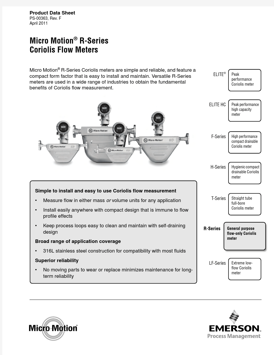
Micro Motion ? R-Series Coriolis meters are simple and reliable, and feature a compact form factor that is easy to install and maintain. Versatile R-Series meters are used in a wide range of industries to obtain the fundamental
benefits of Coriolis flow measurement.
Simple to install and easy to use Coriolis flow measurement ?Measure flow in either mass or volume units for any application ?Install easily anywhere with compact design that is immune to flow profile effects
?
Keep process loops easy to clean and maintain with self-draining design
Broad range of application coverage ?
316L stainless steel construction for compatibility with most fluids
Superior reliability ?
No moving parts to wear or replace minimizes maintenance for long-term reliability
Peak
performance Coriolis meter
General purpose flow-only Coriolis meter
Hygienic compact drainable Coriolis meter
Straight tube full-bore
Coriolis meter
High performance compact drainable Coriolis meter
ELITE ?
R-Series
H-Series
T-Series
F-Series
Product Data Sheet
PS-00363, Rev. F April 2011
Extreme low-flow Coriolis meter
LF-Series
Micro Motion ? R-Series Coriolis Flow Meters
Peak performance high capacity meter
ELITE HC
Micro Motion R-Series Coriolis Flow Meters
Micro Motion Coriolis meters meet a vast range of application needs, ranging from extreme low-flow up to high-flow, high-capacity lines. Cryogenic, hygienic, high-temperature, and high-pressure—Micro Motion meters can handle them all. Micro Motion meters are available with a variety of wetted parts to ensure the best material compatibility.
Coriolis meters.Coriolis meters offer dramatic benefits over traditional volumetric measurement technologies. Coriolis meters:
?Deliver accurate and repeatable process data over a wide range of flow rates and process
conditions.
?Provide direct inline measurement of mass flow and density, and also measure volume flow and temperature—all from a single device.
?Have no moving parts, so maintenance costs are minimal.
?Have no requirements for flow conditioning or straight pipe runs, so installation is simplified
and less expensive.
?Provide advanced diagnostic tools for both the meter and the process.R-Series Coriolis flow meters.Micro Motion
R-Series Coriolis meters are designed to handle most common mass and volume flow measurement applications. The compact case of the R-Series meter allows it to fit almost anywhere, and integral electronics make installation and setup easy.
R-Series meters support a number of digital communication protocols, such as HART?, Modbus?, F OUNDATION fieldbus?, and
PROFIBUS-P A.
Contents
Liquid flow performance . . . . . . . . . . . . . . . . . . . . 3 Gas flow performance. . . . . . . . . . . . . . . . . . . . . . 5 Temperature specifications . . . . . . . . . . . . . . . . . . 7 Pressure ratings . . . . . . . . . . . . . . . . . . . . . . . . . . 9 Vibration limits. . . . . . . . . . . . . . . . . . . . . . . . . . . . 8 Environmental effects . . . . . . . . . . . . . . . . . . . . . . 8Hazardous area classifications. . . . . . . . . . . . . . . .9 Materials of construction. . . . . . . . . . . . . . . . . . . .11 Weight. . . . . . . . . . . . . . . . . . . . . . . . . . . . . . . . . .12 Dimensions. . . . . . . . . . . . . . . . . . . . . . . . . . . . . .13 Fitting options. . . . . . . . . . . . . . . . . . . . . . . . . . . .15 Ordering information. . . . . . . . . . . . . . . . . . . . . . .18
2Micro Motion? R-Series Coriolis Flow Meters
Micro Motion ? R-Series Coriolis Flow Meters 3
Liquid flow performance
Mass Volume (1)(1)Volumetric measurement is based on a process-fluid density of 1g/cm 3 (1000kg/m 3). For fluids with density other than 1g/cm 3
(1000kg/m 3), the volume flow rate equals the maximum mass flow rate divided by the fluid’s density.
lb/min
kg/h gal/min l/h Maximum flow rate
R025S, R025P 1002720122720R050S 3008160368160R100S 120032,65014432,650R200S
3200
87,100
384
87,100
Mass flow accuracy (2)(2)Stated flow accuracy includes the combined effects of repeatability, linearity, and hysteresis. All specifications for liquids are based on
reference conditions of water at 68 to 77 °F (20 to 25 °C) and 15 to 30 psig (1 to 2 bar), unless otherwise noted.±0.5% of rate (3)Volume flow accuracy ±0.5% of rate (3)Mass and volume flow repeatability
±0.25% of rate (3)
(3)When flow rate < (zero stability /0.005), then accuracy = ±[(zero stability /flow rate) × 100]% of rate and
repeatability = ±[?(zero stability /flow rate) × 100]% of rate.
lb/min
kg/h gal/min l/h Zero stability
R025, R025P 0.010.270.00120.27R050S 0.030.820.00360.82R100S 0.12 3.270.0144 3.27R200S
0.32
8.71
0.0384
8.71
4Micro Motion ? R-Series Coriolis Flow Meters
Liquid flow performance continued
Typical accuracy, turndown, and pressure drop with transmitter with MVD Technology
Pressure drop is dependent on process conditions. To determine accuracy, turndown, and pressure drop with your process variables, use Micro Motion’s product selector, available at https://www.doczj.com/doc/e59212369.html,.
Turndown from maximum flow rate
20:110:11:1Accuracy, ± %0.50
0.50
0.50
Pressure drop
psi 0.10.81354bar
0.0070.05
3.4
A c c u r a c y , %
Flow rate, % of maximum
Micro Motion ? R-Series Coriolis Flow Meters 5
Gas flow performance
When selecting sensors for gas applications, measurement accuracy is a function of fluid mass flow rate independent of operating temperature, pressure, or composition. However, pressure drop through the sensor is dependent upon operating temperature,
pressure, and fluid composition. Therefore, when selecting a sensor for any particular gas application, it is highly recommended that each sensor be sized using Micro Motion’s product selector, available at https://www.doczj.com/doc/e59212369.html,.
Mass Volume (1)(1)Standard (SCFM) reference conditions are 14.7 psia and 68 °F . Normal (Nm 3/hr) reference conditions are 1.013 bar and 0 °C.lb/min
kg/h
SCFM
Nm 3/h
Typical flow rates that produce approximately 10 psi (0.68 bar) pressure drop on air (2)
(2)Air at 68 °F (20 °C) and 100 psia (6.8 bar).
R025S, R025P 513060100R050S 15400190310R100S 5013006601000R200S
140
3800
1900
2900
Typical flow rates that produce approximately 50 psi (3.4 bar) pressure drop on natural gas (3)
(3)Natural gas at MW 16.675 at 68 °F (20 °C) and 500 psia (34 bar).
R025S, R025P 15410350580R050S 4211009701600R100S 150400034005900R200S
420
11,000
9700
16,000
Mass flow accuracy (4)(4)Stated flow accuracy includes the combined effects of repeatability, linearity, and hysteresis.
±0.75% of rate (5)(5)
When flow rate < (zero stability / 0.0075), then accuracy = ±[(zero stability / flow rate) × 100]% of rate and repeatability = ±[(zero stability / flow rate) × 100]% of rate.
Mass flow repeatability (4)
±0.5% of rate (5)
lb/min
kg/h Zero stability
R025S, R025P 0.010.27R050S 0.030.82R100S 0.12 3.27R200S 0.32
8.71
6Micro Motion ? R-Series Coriolis Flow Meters
Gas flow performance continued
Typical accuracy and pressure drop with R100S with MVD Technology Air at 68 °F (20 °C), static pressures as indicated on graph
Natural gas (MW 16.675) at 68 °F (20 °C), static pressures as indicated on graph
Standard or normal volumetric capability
Standard and normal volumes are “quasi mass” flow units for any fixed composition fluid. Standard and normal volumes do not vary with operating pressure, temperature, or density. With knowledge of density at standard or normal conditions (available from reference sources), a Micro Motion meter can be configured to output in standard or normal volume units without the need for
pressure, temperature, or density compensation. Contact your local sales representative for more information.
20lb/min
kg/hr Flow rate
A c c u r a c y (± % o f r a t e )
P r e s s u r e d r o
p psi
bar Inches H 20lb/min
kg/hr Flow rate
A c c u r a c y (± % o f r a t e )
P r e s s u r e d r o p
Micro Motion ? R-Series Coriolis Flow Meters
7
Temperature specifications
Accuracy All models ±1 °C ± 0.5% of reading in °C Repeatability
All models
±0.2 °C
Temperature limits (1)(2)(3)
(1)T emperature limits may be further restricted by hazardous area approvals. See pages 9–11.
(2)The temperature extender option allows the sensor case to be insulated without covering the transmitter, core processor, or
junction box, but does not affect temperature ratings.
(3)When ambient temperature is below –40 °F (–40 °C), a core processor must be heated to bring its local ambient temperature to
between –40 °F (–40 °C) and +140 °F (+60 °C). Long-term storage of electronics at ambient temperatures below –40 °F (–40 °C) is not recommended.
A m b i e n t t e m p e r a t u r e o f c o r e p r o c e s s o r o r t r a n s m i t t e r i n °F (°C )
Maximum process temperature in °F (°C)
–148 (–100)
–112 (–80)–76 (–60)–40 (–40)–4 (–20)32 (0)68 (20)104 (40)140 (60)
176 (80)–148 (–100)
–13 (–25)
122 (50)
212 (100)
347 (175)
–103 (–75)
–58 (–50)
32 (0)
77 (25)
167 (75)
257 (125)
302 (150)
8Micro Motion ? R-Series Coriolis Flow Meters
Environmental effects
Vibration limits
Process temperature effect
Process temperature effect is defined as:
?For mass flow measurement, the worst-case zero offset due to process fluid temperature change away from the zeroing temperature.
?For density measurement, the maximum measurement offset due to process fluid temperature change away from the density calibration temperature.
Process temperature effect % of maximum flow rate per °C
R025±0.00175R050±0.00175R100±0.00175R200
±0.00175
Pressure effect
Pressure effect is defined as the change in sensor flow and density sensitivity due to process pressure change away from the calibration pressure (1). Pressure effect can be corrected.
(1)T o determine factory calibration pressure, refer to the calibration document shipped with your sensor. If the data is unavailable, use
20psi (1.4bar).
Pressure effect on mass flow accuracy % of rate per psi % of rate per bar
R025
None None R050None None R100None None R200
–0.001
–0.015
Meets IEC 68.2.6, endurance sweep, 5 to 2000 Hz, 50 sweep cycles at 1.0 g
Micro Motion ? R-Series Coriolis Flow Meters 9
Pressure ratings
Hazardous area classifications
psig
bar Flow tube rating (1)
(1)Over the entire temperature range, according to ASME B31.3.
R025P 2300158R025S 1450100R050S 1500103R100S 1450100R200S
1600
110
PED compliance Sensors comply with council directive 97/23/EC of 29 May 1997 on Pressure Equipment.Housing rating
All models
Housing is not rated for pressure containment.
CSA and CSA-US
Sensor with integrally mounted
Model 1700/2700 transmitter or with core processor
Ambient temperature: –40 to +140°F (–40 to +60°C)Class I, Div. 1, Groups C and D
Class I, Div. 2, Groups A, B, C, and D Class II, Div. 1, Groups E, F , and G
NEPSI and IECEx (1)
(1)For NEPSI and IECEx approvals, refer to the A TEX temperature graphs on the following pages for ambient and process
temperature limits.
Sensor with integrally mounted
Model 1700/2700 transmitter or with core processor Ex ib IIC T1–T5 Gb Sensor with Model 1700/2700 with THUM adapter
Ex ib IIC T1–T4
10Micro Motion ? R-Series Coriolis Flow Meters
Hazardous area classifications continued
ATEX (1)
(1)A TEX “T” rating depends on the maximum temperature shown in the graphs above.
Models R025 and R050 (CIC A2) with core processor or Model 1700/2700 transmitter
Note 1: The maximum surface temperature for dust is as follows: T5:T 95°C, T4:T 130°C, T3:T 195°C, T2 to T1:T 207°C.
Note 2: When installed with the THUM adapter, the T4 rating spans –40 to +127°C.
II 2D Ex ib IIIC T (1)°C Db IP65
Model R100 (CIC A2) with core processor or Model 1700/2700 transmitter
Note 1: The maximum surface temperature for dust is as follows: T5:T 95°C, T4:T 130°C, T3:T 195°C, T2 to T1:T 240°C.
Note 2: When installed with the THUM adapter, the T4 rating spans –40 to +94°C.
II 2D Ex ib IIIC T (1)
°C Db IP65
Sensor fluid temperature (°C)
M a x . a m b i e n t t e m p e r a t u r e (°C )
Sensor fluid temperature (°C)
M a x . a m b i e n t t e m p e r a t u r e (°C )
Micro Motion ? R-Series Coriolis Flow Meters 11
Hazardous area classifications continued
Materials of construction
ATEX (1)
(1)A TEX “T” rating depends on the maximum temperature shown in the graphs above.
Model R200 (C.I.C. A1) with core processor or Model 1700/2700 transmitter
Note 1: The maximum surface temperature for dust is as follows: T5:T 95°C, T4:T 130°C, T3:T 195°C, T2 to T1:T 230°C.
Note 2: When installed with the THUM adapter, the T4 rating spans –40 to +104°C.
II 2D Ex ib IIIC T (1)°C Db IP65
Wetted parts (1)(1)General corrosion guides do not account for cyclical stress, and therefore should not be relied upon when choosing a wetted material
for your Micro Motion meter. Please refer to the Micro Motion corrosion guide for material compatibility information.
All models 316L stainless steel Housing
Sensor 304L stainless steel
Core processor CF-3M stainless steel or polyurethane-painted aluminum; NEMA 4X (IP66)
Integrally mounted transmitter
Polyurethane-painted aluminum; NEMA 4X (IP66)
Sensor fluid temperature (°C)
M a x . a m b i e n t t e m p e r a t u r e (°C )
Weight
Weights provided are the weight of the meter with ANSI CL150 weld neck raised face flanges.
lb kg
Sensor with integrally mounted Model 1700/2700 transmitter R025178 R050189 R1002713 R2004923
Sensor with core processor R025115 R050126 R1002210 R2004320
Sensor with extended core processor R025126 R050136 R1002311 R2004420
12Micro Motion? R-Series Coriolis Flow Meters
Micro Motion ? R-Series Coriolis Flow Meters 13
Dimensions
Sensor
Model No. of
flow tubes Dimensions (1) in inches (mm)(1)For dimensions A and B, see process fitting tables on pages 15–17. For electronics dimensions, see page 14.
Tube ID D E
F
R02520.21 (5.3) 5.12 (130)9.75 (248) 2.81 (71)R05020.35 (8.8) 6.75 (171)11.88 (302) 2.94 (75)R10020.65 (16)9.12 (232)14.88 (378) 4.13 (105)R200
2
1.1 (27)1
2.56 (319)
17.88 (454)
5.62 (143)
Dimensions in
mm (inches)
R025
1.77(45)1.93(49)
NPT female Swagelok fitting dimensions
14Micro Motion ? R-Series Coriolis Flow Meters
Dimensions continued
Electronics
Core processor
Model Dimensions in inches (mm)
M Q S T R025 2.69 (68)8.06 (205) 4.45 (113)9.83 (250)R050 2.69 (68)8.06 (205) 4.45 (113)9.83 (250)R100 2.94 (75)8.31 (211) 4.7 (119)10.08 (256)R200
3.87 (98)
9.25 (235)
5.64 (143)
11.01 (280)
Model 1700/2700
Model Dimensions in inches (mm)
M R025 4.66 (118)R050 4.66 (118)R100 4.91 (125)R200
5.85 (148)
Model 2700 with THUM adapter
Model Dimensions in inches (mm)
M R025 4.66 (118)R050 4.66 (118)R100 4.91 (125)R200
5.85 (148)
Micro Motion ? R-Series Coriolis Flow Meters 15
Fitting options
Model R025S
High-pressure model R025P
Description
Fitting code (1)(1)Fittings listed here are standard options. Other types of fittings are available. Contact your local Micro Motion representative.Dim. A
face-to-face Dim. B
outside diam.in mm in mm 1/2-in ANSI CL150 weld neck raised face flange
11316406 3 1/2891/2-in ANSI CL300 weld neck raised face flange 11416 3/8416 3 3/4951/2-inch ANSI CL600 weld neck raised face flange 11516 7/8428 3 3/4951/2-inch NPT female Swagelok size 8 VCO fitting 31914(2)(2)Dimension specified in table does NOT include fitting length. For installation, modify Dim. A value to include fitting. See
page 13.
356——1/2-inch sanitary fitting (T ri-Clamp ? compatible)12114355125DN15 PN40 weld neck; DIN 2635 type C face
11615 1/4387 3 3/495DN15 PN40 weld neck flange; EN 1092-1 Form B117615 1/4387 3 3/495DN15 PN40 weld neck flange; EN 1092-1 Form D 31015 1/4387 3 3/495DN25 PN40 weld neck flange; EN 1092-1 Form B117215 3/8400 4 1/2115DN25 PN40 weld neck flange; EN 1092-1 Form D
18315 3/8400 4 1/2115DN15 PN100/160 weld neck flange; DIN 2638 type E face 12015 13/16401 4 1/8105DN15 PN100/160 weld neck flange; EN 1092-1 Form B217015 13/16401 4 1/8105DN15 PN100 weld neck flange; EN 1092-1 Form D 17815 13/16401 4 1/810515mm DIN 11851 hygienic coupling
22213 15/16353Rd 34 × 1/8JIS 15mm 10K/20K weld neck raised face flange 12215 7/16393 3 3/495JIS 15mm 40K weld neck raised face flange
221
16 1/2
420
4 1/2115
Description
Fitting code (1)(1)Fittings listed here are standard options. Other types of fittings are available. Contact your local Micro Motion representative.Dim. A
face-to-face Dim. B
outside diam.in mm in mm 15mm DIN PN100/160 weld neck, DIN 2638, type E face 12015 13/16401 4 1/8 ()105DN15 PN100/160 weld neck flange; EN 1092-1 Form B217015 13/16401 4 1/8 ()105DN15 PN100 weld neck flange; EN 1092-1 Form D 17815 13/16401 4 1/8 ()105DN25 PN100 weld neck flange; EN 1092-1 Form B218016 13/16427 5 7/8 ()1501/2-inch NPT female Swagelok size 8 VCO fitting
319
14(2)(2)Dimension specified in table does NOT include fitting length. For installation, modify Dim. A value to include fitting. See
page 13.
355
——
16Micro Motion ? R-Series Coriolis Flow Meters
Fitting options continued
Model R050S
Model R100S
Description
Fitting code (1)(1)Fittings listed here are standard options. Other types of fittings are available. Contact your local Micro Motion representative.Dim. A
face-to-face Dim. B
outside diam.in mm in mm 1/2-inch ANSI CL150 weld neck raised face flange 11318 1/8460 3 1/2891/2-inch ANSI CL300 weld neck raised face flange 11418 1/2469 3 3/4951/2-inch ANSI CL600 weld neck raised face flange 11519
482 3 3/4953/4-inch NPT female Swagelok size 12 VCO fitting 23916 3/8(2)(2)Dimension specified in table does NOT include fitting length. For installation, modify Dim. A value to include fitting. See
page 13.
415——3/4-inch sanitary fitting (T ri-Clamp compatible)
32215 7/8403125DN15 PN40 weld neck flange; DIN 2635 type C face 11617 3/8441 3 3/495DN15 PN40 weld neck flange; EN 1092-1 Form B117617 3/8441 3 3/495DN15 PN40 weld neck flange; EN 1092-1 Form D
31017 3/8441 3 3/495DN15 PN100/160 weld neck flange; DIN 2638 type E face 12017 7/8455 4 1/8105DN15 PN100/160 weld neck flange; EN 1092-1 Form B217017 7/8455 4 1/8105DN15 PN100 weld neck flange; EN 1092-1 Form D 17817 7/8455 4 1/8105DN25 PN40 weld neck flange; DIN 2635 type C face 13117 1/2444 4 1/2115DN25 PN40 weld neck flange; EN 1092-1 Form B117217 1/2444 4 1/2115DN25 PN40 weld neck flange; EN 1092-1 Form D 18317 1/2444 4 1/211515mm DIN 11851 hygienic coupling
22216
407Rd 34 × 1/8JIS 15mm 10K/20K weld neck raised face flange 12217 9/16446 3 3/495JIS 15mm 40K weld neck raised face flange
221
18 5/8
473
4 1/2115
Description
Fitting code (1)(1)Fittings listed here are standard options. Other types of fittings are available. Contact your local Micro Motion representative.
Dim. A
face-to-face Dim. B
outside diam.in mm in mm 1-inch ANSI CL150 weld neck raised face flange 12822 11/16576 4 1/41081-inch ANSI CL300 weld neck raised face flange 12923 3/16588 4 7/81241-inch ANSI CL600 weld neck raised face flange 13023 11/16601 4 7/81241-inch sanitary fitting (T ri-Clamp compatible)
13821 1/4540250DN25 PN40 weld neck flange; DIN 2635 type C face
13121 7/16544 4 1/2115DN25 PN100/160 weld neck flange; DIN 2638 type E face 13722 13/16580 5 1/214025mm DIN 11851 hygienic coupling
23020 9/16522Rd 52 × 1/6DN25 PN40 weld neck flange; EN 1092-1 Form B117921 7/16545 4 1/2115DN25 PN40 weld neck flange; EN 1092-1 Form D 31121 7/16545 4 1/2115DN25 PN100 weld neck flange; EN 1092-1 Form B218022 7/8581 5 1/2140DN25 PN100 weld neck flange; EN 1092-1 Form D 18122 7/8581 5 1/2140JIS 25mm 10K/20K weld neck raised face flange 13921 11/16550 4 15/16125JIS 25mm 40K weld neck raised face flange
229
22 15/16582
5 1/8130
Micro Motion ? R-Series Coriolis Flow Meters 17
Fitting options continued
Model R200S
Description
Fitting code (1)(1)Fittings listed here are standard options. Other types of fittings are available. Contact your local Micro Motion representative.
Dim. A
face-to-face Dim. B
outside diam.in mm in mm 1 1/2-inch ANSI CL150 weld neck raised face flange 34124 3/462951271 1/2-inch ANSI CL300 weld neck raised face flange 34225 1/4642 6 1/81551 1/2-inch ANSI CL600 weld neck raised face flange 34325 3/4654 6 1/81552-inch ANSI CL150 weld neck raised face flange 41824 7/863261522-inch ANSI CL300 weld neck raised face flange 41925 3/8645 6 1/21652-inch ANSI CL600 weld neck raised face flange 42026 1/8664 6 1/21651 1/2-inch sanitary fitting (T ri-Clamp compatible)35123 1/45912502-inch sanitary fitting (T ri-Clamp compatible)
35222 7/8581 2 1/264DN40 PN40 weld neck flange; DIN 2635 type C face 38123 9/16598 5 15/16150DN50 PN40 weld neck flange; DIN 2635 type C face 38223 5/8600 6 1/2165DN50 PN100 weld neck flange; DIN 2637 type E face 37825 1/46417 11/16195DN40 PN40 weld neck flange; EN 1092-1 Form B136823 1/4594 5 15/16 150DN40 PN40 weld neck flange; EN 1092-1 Form D 31223 1/4594 5 15/16150DN40 PN100 weld neck flange; EN 1092-1 Form B236324 3/4628 6 11/16170DN40 PN100 weld neck flange; EN 1092-1 Form D 36624 3/4628 6 11/16170DN50 PN40 weld neck flange; EN 1092-1 Form B136923 5/8600 6 1/2165DN50 PN40 weld neck flange; EN 1092-1 Form D 31623 5/8600 6 1/2165DN50 PN100 weld neck flange; EN 1092-1 Form B236525 1/46417 11/16195DN50 PN100 weld neck flange; EN 1092-1 Form D 36725 1/46417 11/1619540mm DIN 11851 hygienic coupling 35323 3/16589Rd 65 × 1/650mm DIN 11851 hygienic coupling
35423 1/4591Rd 78 × 1/6JIS 40mm 10K weld neck raised face flange 38523 7/16595 5 1/2140JIS 40mm 20K weld neck raised face flange 38723 7/16595 5 1/2140JIS 50mm 10K weld neck raised face flange 38623 7/16595 6 1/8155JIS 50mm 20K weld neck raised face flange 38823 5/8600 6 1/8155JIS 50mm 40K weld neck raised face flange
389
25 7/16
646
6 1/2165
18Micro Motion ? R-Series Coriolis Flow Meters
Ordering information
Model
Product description Standard sensor models
R025S R-Series sensor; 1/4-inch (6 mm); 316L stainless steel R050S R-Series sensor; 1/2-inch (12 mm); 316L stainless steel R100S R-Series sensor; 1-inch (25 mm); 316L stainless steel R200S
R-Series sensor; 2-inch (50 mm); 316L stainless steel High-pressure models
R025P R-Series sensor; 1/4-inch (6 mm); 316L stainless steel; 2300 psi (158 bar) tube rating Code Process connection
###See fittings option tables on pages 15–17Code Case options N Standard case Code Electronics interface
Q 4-wire polyurethane-painted aluminum integral core processor for remotely mounted transmitter with MVD technology A 4-wire stainless steel integral core processor for remotely mounted transmitter with MVD technology
V 4-wire polyurethane-painted aluminum integral core processor with extended mount for remotely mounted transmitter with MVD technology
B 4-wire stainless steel integral core processor with extended mount for remotely mounted transmitter with MVD technology
C Integrally mounted Model 1700 (all output options) or Model 2700 (F OUNDATION fieldbus or PROFIBUS-P A) transmitter Code
Conduit connections
Electronics interface codes Q, A, V , and B
B 1/2-inch NPT — no gland E M20 — no gland
F Brass/nickel cable gland (cable diameter 0.335 to 0.394 inches [8.5 to 10 mm])G
Stainless steel cable gland (cable diameter 0.335 to 0.394 inches [8.5 to 10 mm])Electronics interface code C
A No gland Code Approvals
M Micro Motion standard (no approval)
N Micro Motion standard / PED compliant (no approval)C CSA (Canada only)
A CSA C-US (U.S.A. and Canada)
Z ATEX — Equipment category 2 (Zone 1) / PED compliant I IECEx Zone 1P (1)
(1)Available only with language code M (Chinese).
NEPSI
Continued on next page
Ordering information continued
Code Language
A Danish CE requirements and English manual
C Czech installation manual
D Dutch C
E requirements and English manual
E English installation manual
F French installation manual
G German installation manual
H Finnish CE requirements and English manual
I Italian installation manual
J Japanese installation manual
M Chinese installation manual
N Norwegian CE requirements and English manual
O Polish installation manual
P Portuguese installation manual
S Spanish installation manual
W Swedish CE requirements and English manual
B Hungarian CE requirements and English manual
K Slovak CE requirements and English manual
T Estonian CE requirements and English manual
U Greek CE requirements and English manual
L Latvian CE requirements and English manual
V Lithuanian CE requirements and English manual
Y Slovenian CE requirements and English manual
Code Future option 1
Z Reserved for future use
Code Future option 2
Z Reserved for future use
Code Future option 3
Z Reserved for future use
Code Factory options
Z Standard product
X ETO product
Typical model number:R025S 113 N C A C E Z Z Z Z
Micro Motion? R-Series Coriolis Flow Meters19
!"" #"
$ % !" !"
& $ % ! '!(
) * !" !! ! ( ! + !' ' , !! ! " !" - , ! "# (" !
. '(! !!!
+ / " " #
010 "' (
2 3 4 '(! ( (
4 5 '
6 / 5 " ! '
& ( (
7 8 ( '
9 : : ; ' ' # #
+ ; $#!% # "
1 $ "% " ' '#
< ; $ % ! #( #
4 $( % "" ###" !##
$ #% " " (" (
$# % ( " " ; ' ( ! #
Micro Motion—The undisputed leader in flow and density measurement
World-leading Micro Motion measurement solutions from Emerson
Process Management deliver what you need most:
Technology leadership
Micro Motion introduced the first reliable Coriolis meter in 1977. Since
that time, our ongoing product development has enabled us to
provide the highest performing measurement devices available.
Product breadth
From compact, drainable process control to high flow rate fiscal
transfer—look no further than Micro Motion for the widest range of
measurement solutions.
Unparalleled value
Benefit from expert phone, field, and application service and support
made possible by more than 600,000 meters installed worldwide and
over 30years of flow and density measurement experience.
?2011 Micro Motion, Inc. All rights reserved.
The Emerson logo is a trademark and service mark of Emerson Electric Co. Micro Motion, ELITE, ProLink, MVD and MVD Direct Connect are marks of one of the Emerson Process Management family of companies. All other trademarks are property of their respective owners.
Micro Motion supplies this publication for informational purposes only. While every effort has been made to ensure accuracy, this publication is not intended to make performance claims or process recommendations. Micro Motion does not warrant, guarantee, or assume any legal liability for the accuracy, completeness, timeliness, reliability, or usefulness of any information, product, or process described herein. We reserve the right to modify or improve the designs or specifications of our products at any time without notice. For actual product information and recommendations, please contact your local Micro Motion representative.
For a complete list of contact information and web sites, please visit: https://www.doczj.com/doc/e59212369.html,/home/contacts/global
艾默生质量流量计选型、功能及应用领域 艾默生质量流量计能够直接测量质量流量和密度,是一个仪器流量计。艾默生质量流量计选择用于此应用的高准一体式的变送器和应用平台能够提供精确的批次控制和对质量流量、总流量、密度和温度的连续监控。本文主要介绍一下艾默生质量流量计选型、功能及应用领域。 艾默生质量流量计选型 艾默生质量流量计的选型与一般流量计的选型有很大的不同: 其一,流量再大质量流量计都可以测量,(而其它流量计可能量程超限而不工作或造成机械部件损坏),只是要牺牲压力损失作为代价。 其二,艾默生质量流量计质量流量计的量程比,也是与流量计两端的压力损失有很大的关系,即量程比越大,压力损失也就越大。 其三,当一台艾默生质量流量计的管径大小决定了,流速越大,精度可以得到保证但所带来的压力损失也就大,我们通常从质量流量计的产品样本看到的量程比系基于水为介质和1kg压力损失作为参考给出的量程比...(只是对液体介质而言),所以要想选出合适工况的质量流量计能给出整个过程工艺参数和管道所允许压力损失,根据这些工艺条件,相信艾默生质量流量计的专业流量工程师会给出合理的选型和报价。 艾默生质量流量计选型 艾默生质量流量计的选型与一般流量计的选型有很大的不同: 其一,流量再大质量流量计都可以测量,(而其它流量计可能量程超限而不工作或造成机械部件损坏),只是要牺牲压力损失作为代价。 其二,艾默生质量流量计质量流量计的量程比,也是与流量计两端的压力损失有很大的关系,即量程比越大,压力损失也就越大。 其三,当一台艾默生质量流量计的管径大小决定了,流速越大,精度可以得到保证但所带来的压力损失也就大,我们通常从质量流量计的产品样本看到的量程比系基于水为介质和1kg压力损失作为参考给出的量程比...(只是对液体介质而言),所以要想选出合适工况的质量流量计能给出整个过程工艺参数和管道所允许压力损失,根据这些工艺条件,相信艾默生质量流量计的专业流量工程师会给出合理的选型和报价。 艾默生质量流量计应用领域 (1)石油行业,如原油产量计量、含水率、单井产量计量、原油运输计量
2700/1700面板操作 一. 屏幕显示说明: SELECT--- 确认键 SCROLL---- 选择键 LED---状态指示灯 二. 显示器密码: 如果需要密码,CODE的字样就会出现在密码屏幕的顶部. 输入密码时候,通过使用SCROLL来选择数字, 并用SELECT移到下一个字符, 一次只好输入一个字符. 如果你面对显示器密码屏幕, 却不知道密码, 在60秒内不按下任何显示器光敏开关.则此密码屏幕将自动退回到初始屏幕. 三. 调零步骤:
四. 显示器回路测试:
五. 显示器查看报警: LED指示灯状态及报警查看
六. 管理累积量和库存量:
七: 测量单位设置: SELECT+SCROLL 按4秒SEE ALARM [SCROLL] OFFLINE MAINTAIN [SELECT] [SCROLL] CONFIG [SELECT] MASS [SELECT] 可以按SCROLL选择你要的单位选定后按SELECT 按SCROLL直到出现EXIT [SELECT] 体积单位和密度单位设置和上述步骤相同 八量程设置(LRV URV) [SELECT+SCROLL] 按4秒SEE ALARM [SCROLL] OFFLINE MAINTAIN [SELECT] 继续按SCROLL直到出 现MAO1 [SELECT] SRC MAO1 [SELECT] MFLOW [SELECT] SRC MAO1 [SCROLL] 4 MAO1 输入最小量程 [SCROLL+SELECT] 4 MAO1 [SCROLL] 20 MAO1 [SELECT] 输入最 大量程 [SELECT+SCROLL] 20 MAO1 [SCROLL] EXIT 按SELECT退出. 其他量程设置和上述步骤相同. NOTE: SELECT+SCROLL 表示两个键同时按下
2700/1700面板操作 一.屏幕显示说明: SELECT---确认键 SCROLL----选择键 LED---状态指示灯二.显示器密码: 如果需要密码,CODE的字样就会出现在密码屏幕的顶部.输入密码时候,通过使用SCROLL来选择数字,并用SELECT移到下一个字符,一次只好输入一个字符. 如果你面对显示器密码屏幕,却不知道密码,在60秒内不按下任何显示器光敏开关.则此密码屏幕将自动退回到初始屏幕. 三.调零步骤: Scroll OFF-LINE MAINT I Sorotl OFF-LIME ZZERO exit
四.显示器回路测试: SQt MA01 Sei MAO3 Select a Scroll ■AflIliTStrril Jfrw的I 叮 ScroJi OFF-LINE MAINT Sekci ScrdI OF匚LINE SIM 鼬led Scroll S*tFO Sd&ct Scroll * Sel DOI Sei DOz Select Scroll 4 mA 12 mA 20 mA 1 KHz ID KHi ON O'FF
五.显示器查看报警: LED指示灯状态及报警查看 报警按照报警队列中前优先级排列.要查S队列中杲指定报警: 1,同时按下Scroll II和fel旣t按钮.当屏幕上出现“SEE ALAR/时,松开按 钮. 卷阅图7T 2,按Select按钮 3,如杲屏幕上交替岀现FCK ALI/轧则按Scroll I按粗. 4如果屏幕上岀现50 ALART ,则到第6步, 5,按ScBll按钮S看队列中的每人ft警。S了解显示器显示的报置比码的含义’ 请参阅第KU1章节: ft按Seel I按钮直到屏暮上a现'*EXIT" ° 7,技Select按a
艾默生质量流量计变送器曾辰夷 发表时间:2018-05-18T11:41:22.447Z 来源:《基层建设》2018年第3期作者:曾辰夷[导读] 摘要:高标准(微运动)MVD1700 2700型传感器的模拟输出中文菜单,提供一个更友好的人机界面和菜单操作的全面优化经验,并有丰富的面板配置功能。 武汉凯迪电力工程有限公司湖北武汉 430000 摘要:高标准(微运动)MVD1700 2700型传感器的模拟输出中文菜单,提供一个更友好的人机界面和菜单操作的全面优化经验,并有丰富的面板配置功能。最近,艾默生高精度质量流量计发射机新的中文显示选项。与中国显示选项、1700、2700型模拟输出传感器,一个更大的显示器,提供一个更友好的人机界面和菜单操作经验的综合优化,艾默生过程管理是满足中国市场的需求大部分客户的本地语言和 习惯,并启动一个新产品。 关键词:质量流量计;变送器; 1 前言 高准1700和2700发射机一直是一种受欢迎的广受认可的产品。在中文新显示选项中,发射机仍是MVD多变量数字技术的延续,高速信号处理和快速响应能力,支持智能仪表在线自检(SMV)等先进的诊断功能。无论是贸易交接、过程控制还是测量监控,支持中国展示的1700-2700发射机是中国客户的理想选择。支持中国1700,2700打字发送器可以在中文和英文之间切换。多行大屏幕液晶显示大大丰富了单屏内容的内容,并显示了更细的细节。光感应操作按钮已增加到3个,简化了操作程序。为实现菜单功能的快速转换提供了多种组合关键操作方法。同时,产品充分优化了操作菜单结构,增加了多个面板配置功能。用户无需任何外部配置工具即可轻松完成字段配置操作。操作菜单还提供了报警代码的详细诊断信息,以便用户能够快速理解警报的原因并及时做出响应。仪器的维护方便快捷。 2 用质量流量计测量密度 2.1质量流量计安装要求 质量流量计的安装通常需要考虑必要的和向后的直管段,并且应该远离节流装置,如阀门和孔。质量流量计通常用于旁路安装,以确保流经流量计的质量中等速度不能低于1m/s,防止质量流量计内的介质沉积造成的拥堵,并考虑管道的安装自动排水和冲洗阀门。一些厂家的建议将是在泵的下游安装质量流量计(以避免真空),由于从底部到上部的介质会造成垂直管道的低空,往往会带来一些不便的管道工艺设计。因为在湿法脱硫工程中,测量中酸度和高固含量,在较大的速度下会导致较大的磨损量,因此,在选择材料时应该考虑的是耐酸和耐磨性(一般认为是哈茨合金)。 2.2质量流量计的缺点 在实际使用中,艾默生力质量流量计在首次使用时一般准确、准确。在使用一段时间后,可能是由于操作环境差,测量线不断振动,测量结果往往不准确;同时,在使用过程中要定期清洗,否则容易堵塞。此外,爱默生部队的质量流量计非常高,通常超过10万元,而便宜的1万到5万元。 3. 项目膜片压力传感器的测量密度 3.1安装方法和原理 采用压力变送器间接测量塔内液体的密度,安装简单,价格便宜,但适用于精度要求不高的情况。测量方法如下:2膜片法兰压力变送器安装在吸收塔的相对位置和下2个。为了防止塔内介质的沉积,在吸收塔上安装了大型搅拌器。连续搅拌,介质不会凝固,但在吸收器的底部,由于搅拌器的作用,介质固体颗粒的连续沉降会凝结。 3.2压力传感器的选择 由于测量方法的误差,通常需要测量精度高的膜片法兰压力传感器。由于高塔的介质易于压缩,一般采用大直径法兰直径的变送器(如DN80),在选型时使用洗涤环,使堵塞时用冲洗水冲洗维修。为了适应酸性环境,发射接收机的材料通常由哈吉合金制成。3051L液位变送器的精度为0.075%,体积小,重量轻,易于安装和维护。这种压力变送器目前市场价格为人民币,远低于质量流量计的价格,艾默生简单安装,不占用空间,没有特殊要求,但应防止表面凝固堵塞。 4 气液两相流实验 主要气液两相流流量测量误差和流体流动,空气含量,传感器安装位置和形状等因素,这些因素将导致不同的流体模型,如气泡流、环状流、层状流,等等。在两相流实验装置,科里奥利传感器和其安装方向是固定的,而影响两相流测量结果的主要因素是流体流动和气体含量。 4.1测量流体流动 在气液两相流测量中,实际测量的流量值与实际值之间存在一定误差。虽然这种偏置测量值不代表实际值,但仍被认为是两相流测量误差的影响因素之一。 4.2测量密度下降 两个相的体积比是一个重要的参数,如气液两相,气体体积分数(GVF)用于描述气体混合的量。在工业应用中,气体体积流动不容易获得,而真正的GVF无法在线计算。然而,当液体密度已知时,由发射机测量的流体密度可以间接地反映出GVF的大小。事实上,单相液体的密度通常是已知的,并且可以作为发射器的常数。因此,通过实时观测流体密度的变化可以得到混合气体的含量。 5 结束语 综上所述,测量塔内液体密度时,质量流量计的测量精度较高,但安装管道复杂且昂贵。然而,使用压力传感器的缺点是精度不高,但安装简单,操作稳定,易于维护,最重要的是价格便宜。在脱硫工程竞争日趋激烈和合同价格较低的情况下,采用压力变送器测量密度是一个很好的选择,已在许多项目中得到应用。 参考文献 [1]刘翠,侯其立,熊文军,徐科军,石岩,方敏,蒋荣慰,陶波波.面向微弯型科氏质量流量计的高精度过零检测算法实现[J].电子测量与仪器学报,2014,28(06):675-682.
艾默生高准质量流量计的正确安装 质量流量计正确良好的安装是其可靠工作、准确测量的前提,必须予以充分的重视,安装时要有专门的技术人员严格把关。 1、安装场所 远离大的振动设备及强力电磁场干扰场所,测量液态物料避免安装在工艺管线的最高点,要方便维护和拆卸; 2、安装方式 气体物料,传感器弯管竖直向上,液体物料,传感器弯管竖直向下,特殊情况也可竖直向上,应避免弯管水平或倾斜; 压力要求:背压要求可以使介质始终充满传感器测量管,避免出现半管而导致测量不准确。因此,保证安装在管线中的传感器有足够的背压是十分重要的。当背压不满足要求时,可考虑在管线中加装背压调节器。 要做到这一点,一是将传感器装在靠近泵的出口侧,或者装在上升管道的较低部位来测液体,而且流量计下游上升管道的高度应不低于2m(视介质密度而定)。 3、避免电磁干扰和射频干扰 安装在大电机、射频发生器、变压器、大功率开关等设备附近,传感器中测量管的自激谐振动会受到干扰,而且检测器检测出来的微弱信号也有可能被淹没在干扰信号之中。 另外,连接仪表各部分的电缆的走线也不要覆盖在这些可能产生干扰的设备上面,最好不要靠近它们,也不要靠近高压供电电缆或类
似的电磁干扰和射频干扰 (EMI/RFI)源。 4、避免振动的影响 科氏力式质量流量计的原理和结构都决定了外界振动对它会造 成影响,虽然专门的安装技术 (例如采用坚固的管支架等)能够减小外界振动的影响,制造厂家也在竭力改进结构以提高抗外界干扰振动的能力,但流量计的安装场所还是应该尽量远离大功率泵、电机等强振动千扰源。若需要在管线振动大的管线中安装大口径流量计,有时要用膨胀节来消振,但必须在膨胀节与传感器之间加装带有坚固支撑的短接,否则,由于管道的伸缩造成附加应力,显示数据将会失准。 5、不能用流量计作为管道的支撑;流量计不能用来矫正管道法兰的错位和用来拉紧管道,导致流量计承受应力影响测量准确度。 6、其他注意事项 除以上几点要着重考虑之外,当选择安装场所时,还应遵循下列原则: 当用科氏力式质量流量计测量液体介质,特别是易汽化的液体或含有少量气体的液体介质时,应把流量传感器安装在管道的较低处,而不要将传感器安装在管道的最高处; 当用科氏力式质量流量计测量气体介质,特别是非干燥气体或在高压下易液化的气体介质时,应把流量传感器安装在管道的较高处,而不要将传感器安装在管道的最低处。 7、传感器安装方式的选择 传感器的安装一般分为垂直安装与水平安装两种方式。传感器的
曲為”歼心 —一.屏幕显示说明: SELECT---确认键 LED---状态指示灯 二.显示器密码: 如果需要密码,CODE 的字样就会出现在密码屏幕的顶部.输入密码时候,通过使 用SCROLL 来选择数字,并用SELECT 移到下一个字符,一次只好输入一个字符 如果你面对显示器密码屏幕,却不知道密码,在60秒内不按下任何显示器光敏开 关.则此密码屏幕将自动退回到初始屏幕? 三.调零步骤: ~T~ Sera 11 ★ OFF-LINE M/VINT Exit 2700/1700面板操作 SCROLL----选择键 TEST c>K 51试威珈 I ScroH I EST FAIL 门團或头M 咬;
四.显示器回路测试: SQt MA01 Sei FJAOi Serai OFF-LINE MAINT OFF LINE SKI fiel DOi Sei &02 4 mA 12 mA 20 mA Se曲 Scwll *L 1 KHz iu KH7 Select I Scro ll Seleuc 曲IM 输出烟 输岀数F 回菇汎试或功 国哄k<\捋饪启止访真 Scroll ExM
曲為”呎… 五?显示器查看报警: LED指示灯状态及报警查看 (I)如累播讐菜单我禁止.左这和嗜况下.状态指示粹不再闪际 报警按照报警队列中的优先级排列,要S6IU列中某指定报書: 1. 同时按下Scroll和斛託t按钮.当屏專上出现“SEE ALARM”时,松ffftffl 卷阅图 7T° 2. 按Select按钮 3. 如杲屏幕上交替岀现TCK ALL” Mr则按Scroll按钮 4. 如果屏幕上岀a ^NO ALARM",则到第6步’ 5. 技S GB II按钮查看队列中的每木报警“要了解显示話显示的梶醫代码的含义情 参阅第011章节, 竹KScrol I按钮直到層暮上出现“EXITS, 7<技Select按迅
艾默生质量流量计安装 质量流量计正确良好的安装是其可靠工作、准确测量的前提,必须予以充分的重视,安装时要有专门的技术人员严格把关。 1、安装场所 远离大的振动设备及强力电磁场干扰场所,测量液态物料避免安装在工艺管线的最高点,要方便维护和拆卸; 2、安装方式 气体物料,传感器弯管竖直向上,液体物料,传感器弯管竖直向下,特殊情况也可竖直向上,应避免弯管水平或倾斜; 压力要求:背压要求可以使介质始终充满传感器测量管,避免出现半管而导致测量不准确。因此,保证安装在管线中的传感器有足够的背压是十分重要的。当背压不满足要求时,可考虑在管线中加装背压调节器。 要做到这一点,一是将传感器装在靠近泵的出口侧,或者装在上升管道的较低部位来测液体,而且流量计下游上升管道的高度应不低于2m(视介质密度而定)。 3、避免电磁干扰和射频干扰 安装在大电机、射频发生器、变压器、大功率开关等设备附近,传感器中测量管的自激谐振动会受到干扰,而且检测器检测出来的微弱信号也有可能被淹没在干扰信号之中。 另外,连接仪表各部分的电缆的走线也不要覆盖在这些可能产生干扰的设备上面,最好不要靠近它们,也不要靠近高压供电电缆或类似的电磁干扰和射频干扰 (EMI/RFI)源。 4、避免振动的影响 科氏力式质量流量计的原理和结构都决定了外界振动对它会造成影响,虽然专门的安装技术 (例如采用坚固的管支架等)能够减小外界振动的影响,制造厂家也在竭力改进结构以提高抗外界干扰振动的能力,但流量计的安装场所还是应该尽量远离大功率泵、电机等强振动千扰源。若需要在管线振动大的管线中安装大口径流量计,有时要用膨胀节来消振,但必须在膨胀节与传感器之间加装带有坚固支撑的短接,否则,由于管道的伸缩造成附加应力,显示数据将会失准。 5、不能用流量计作为管道的支撑: 流量计不能用来矫正管道法兰的错位和用来拉紧管道,导致流量计承受应力影响测量准确度。 6、其他注意事项 除以上几点要着重考虑之外,当选择安装场所时,还应遵循下列原则: A.当用科氏力式质量流量计测量液体介质,特别是易汽化的液体或含有少量气体的液体介质时,应把流量传感器安装在管道的较低处,而不要将传感器安装在管道的最高处; B.当用科氏力式质量流量计测量气体介质,特别是非干燥气体或在高压下易液化的气体介质时,应把流量传感器安装在管道的较高处,而不要将传感器安装在管道的最低处。 7、传感器安装方式的选择 传感器的安装一般分为垂直安装与水平安装两种方式。传感器的安装方式应依据被测流体的类型及传感器自身结构加以选择。
P/N 2007年7月 简明使用手册
目录 第一章传感器安装 (3) 1.1概述 (3) 1.2安装注意事项 (3) 1.3传感器的安装方向 (4) 1.4电气连接注意事项 (5) 第二章仪表接线与上电 (6) 2.1概述 (6) 2.2变送器的型号识别。 (6) 2.3变送器与传感器连接 (7) 2.4最大布线距离 (8) 2.5电源规格 (9) 2.6变送器、显示组件方向调整 (10) 2.7变送器输出 (12) 第三章流量计组态 (15) 3.1概述 (15) 3.2组态项目 (15) 3.3变送器的显示器面板结构 (16) 3.4组态过程变量的测量单位 (16) 3.5组态变送器的毫安输出 (17) 3.6组态变送器的脉冲/频率输出 (17) 3.7变送器的回路测试 (18) 3.8 显示器菜单功能 (3) 3.9流量计调零 (27) 第四章流量计投用及报警状态 (28) 4.1流量计投用 (28) 4.2获取报警 (28) 附录1报警代码含义表 (29) 附录2核心处理器检查 (34) 附录3传感器检查 (35) 附录4软件版本4.x变送器的显示器菜单 (37)
第一章传感器安装 1.1 概述 相对于其他类型的流量计,质量流量计具有安装简便、易于使用、测量精度高以及直接 质量测量等优点,尤其是没有直管段要求的特点,用户可因地制宜的选择安装位置,节 约安装成本。 1.2 安装注意事项 1.2.1 安装位置应避免电磁干扰。传感器、变送器的安装位置以及电缆铺设应尽量远离易产生 强电磁场的设备,如大功率马达、变压器设施、变频设备等。 1.2.2 工艺管道应对中,两侧法兰应平行。严禁用传感器硬行拉直上、下游工艺管道,否则将 影响测量甚至损坏传感器。另外在两侧的工艺管道近法兰处(约2~10倍管径处)应有 稳固的支撑。 1.2.3 在传感器的上、下游管道上,建议安装截止阀及旁路以方便调零、日常维护及确保传感 器在不工作时亦可处于满管状态。使用流量计下游的调节阀进行流量控制。 1.2.4 在测量易汽化介质时,流量计下游建议安装压力表,供检查下游压力,流量计后建议工 艺管与流量计保持同口径一段距离,以及流量计后有阀门可以用以调节适当的背压,防 止汽化或气穴发生。若介质在流量计中发生汽化或气穴将影响测量精度,严重时导致流 量计无法正常工作。 1.2.5 安装时要注意流量计外壳上的流向标志,其箭头指向与变送器内部组态的流量方向是一 致的。 流量方向箭头 工艺连接 吹扫接头(可选) 核心处理器外壳 认证标签 标定标签 注:质量流量计可以双向使用。如果安装方向与实际流向相反,修改变送器内的流向组 态即可。
艾默生质量流量计工作原理 工作原理作为科里奥利效应的实际应用,科里奥利质量流量计的工作原理是使得有介质流经的流量管发生振动。尽管振动并非完整的圆形,仍形成了旋转坐标系统,从而引发科里奥利效应。传感器检测并分析流量管频率、相位差和振幅的变化。具体的检测方法会因流量计设计不同而不同。这些被观测到的变化代表了流体的质量流量和密度。 质量流量测量测量管在力的作用下发生摆动,从而产生正弦波。流量为零时,两根管道同相地发生振动。有流量时,科里奥利力促使管道发生弯曲,从而引发相偏移。测量正弦波之间的时差,此时差与质量流量成正比。A.入口检测位移B.无流量C.出口检测位移D.时间E.入口检测位移F.有流量G.出口检测位移H.时差I.时间密度测量测量管以其固有频率振动。管道内介质质量的变化将导致管道固有频率发生相应的变化。通过管道的频率变化来计算密度。温度测量温度作为测量变量,可用作输出量。此外,温度还可用于在传感器内部补偿温度变化对杨氏弹性模量的影响。艾默生质量流量计仪表特性:介质质量流量的测量精度独立于操作温度、压力或组分。然而,传感器的压降取决于操作温度、压力和介质的组分。规格与功能随型号而异,某些型号可能有较少的可用选项。具有CMF代号的所有仪表(CMF、CMFHC、CMFS)均为ELITE仪表类下的仪表,并且应视为具有与其他ELITE类仪表相同的质量与规格(特别注明者除外)。基本型号代码(例如CMF100M)末尾的字母表示接液部件的材料和/或应用名称:M=316L不锈钢、L=304L不锈钢、H=镍合金C22、P=高压、A=高温316L不锈钢、B=高温镍合金C22、Y=超级双相(UNSS32750)。
Product Data Sheet PS-00374, Rev. AB June 2015 Micro Motion ? ELITE ? Coriolis Flow and Density Meters Ultimate real world performance ? Unchallengeable ELITE performance on liquid mass flow, volume flow, and density measurements ?Best-in-class gas mass flow measurement ?Reliable two-phase flow measurement for the most challenging applications ? Designed to minimize process, mounting, and environmental effects Best fit-for-application ? Scalable platform for the widest range of line size and application coverage including hygienic, cryogenic, high pressure, and high temperature ? Available with the broadest range of I/O offerings highlighted by expansive digital protocol support Superior measurement confidence ? Smart Meter Verification delivers complete, on-line verification of device health and performance, continuously or on-demand at the press of a button ? Globally leading ISO/IEC 17025 calibration facilities offers best in class uncertainty of ±0.014% ? Intelligent sensor design mitigates the need for zero calibration in the field (/,7( 3HDN SHUIRUPDQFH ) 6HULHV ([FHSWLRQDO SHUIRUPDQFH FRPSDFW GUDLQDEOH + 6HULHV +\JLHQLF FRPSDFW GUDLQDEOH 7 6HULHV 6WUDLJKW WXEH VDQLWDU\ 5 6HULHV *HQHUDO SXUSRVH IORZ DQG GHQVLW\ /) 6HULHV ([WUHPH ORZ IORZ
MODBUS 485通讯手册 MODBUS/RS485是现在最流行的一种布网方式,其特点是实施简单方便 ,传输数据量大,特别是在油品行业RS485简直是一统天下。 EMERSON 的高准系列质量流量计都支持MODBUS/RS485数据通讯,通过一组信号电缆,就可以将流量计的质量瞬时流量质量瞬时流量、、质量累积量质量累积量、、体积体积瞬时瞬时瞬时流量流量流量、、体积累积量积累积量、、温度温度、、密度等参数传到上位机。 一、流量流量变送器变送器485接线接线端子端子
二、变送器变送器通讯通讯通讯协议和设备地址协议和设备地址协议和设备地址组态组态 1、1700/2700/新型9739架装型变送器 1)同时按SCROLL (左)键和SELECT (右)键4秒以上(指示灯闪烁)。 2)按左键翻到OFF-LINE MAINT 菜单,再按右键-左键-右键-左键后进入菜单。 3)如果出现CODE?则输入密码,一般出厂设为1234。按左键增加数字,按右键移位。 4)按左键翻到OFF-LINE CONFIG ,再按右键进入。 5)按左键到CONFIG -COMM ,按右键进入,再按左键选择要修改的通讯方式,按右键进入. PROTOCOL---选择通讯协议 BAUD---设置波特率 PARITY---奇偶校验 STOP BITS---停止位 ADDRESS MBUS---设备地址 2、3000系列变送器 进入Management---Configuration---Digital communication---Configure RS-485 1)Protocol---设置通信协议 2)Configure protocol BAUD---设置波特率 PARITY---奇偶校验 Data bits—数据位 STOP BITS---停止位 Polling address---设备地址
Micro Motion ? R-Series Coriolis meters are simple and reliable, and feature a compact form factor that is easy to install and maintain. Versatile R-Series meters are used in a wide range of industries to obtain the fundamental benefits of Coriolis flow measurement. Simple to install and easy to use Coriolis flow measurement ?Measure flow in either mass or volume units for any application ?Install easily anywhere with compact design that is immune to flow profile effects ? Keep process loops easy to clean and maintain with self-draining design Broad range of application coverage ? 316L stainless steel construction for compatibility with most fluids Superior reliability ? No moving parts to wear or replace minimizes maintenance for long-term reliability Peak performance Coriolis meter General purpose flow-only Coriolis meter Hygienic compact drainable Coriolis meter Straight tube full-bore Coriolis meter High performance compact drainable Coriolis meter ELITE ? R-Series H-Series T-Series F-Series Product Data Sheet PS-00363, Rev. F April 2011 Extreme low-flow Coriolis meter LF-Series Micro Motion ? R-Series Coriolis Flow Meters Peak performance high capacity meter ELITE HC