Light Sterile Neutrino Effects at theta_13-Sensitive Reactor Neutrino Experiments
- 格式:pdf
- 大小:984.97 KB
- 文档页数:12

第一章1、晶体一般的特点是什么?点阵和晶体的结构有何关系?答:(1)晶体的一般特点是:a 、均匀性:指在宏观观察中,晶体表现为各部分性状相同的物体b 、各向异性:晶体在不同方向上具有不同的物理性质c 、自范性:晶体物质在适宜的外界条件下能自发的生长出晶面、晶棱等几何元素所组成凸多面体外形d 、固定熔点:晶体具有固定的熔点e、对称性:晶体的理想外形、宏观性质以及微观结构都具有一定的对称性(2)晶体结构中的每个结构基元可抽象成一个点,将这些点按照周期性重复的方式排列就构成了点阵。
点阵是反映点阵结构周期性的科学抽象,点阵结构是点阵理论的实践依据和具体研究对象,它们之间存在这样一个关系:点阵结构=点阵+结构基元点阵=点阵结构-结构基元2、什么是同质多晶?什么是类质同晶?一些组成固定的化合物,由于其内部微粒可以以不同的方式堆积,因而产生不同种类的晶体,我们把这种同一化合组成存在两种或两种以上晶体结构形式的现象为同质多晶现象。
在两个或多个化合物中,如果化学式相似,晶体结构形式相同,并能互相置换的现象,我们称之为类质同晶现象。
3、产生晶体缺陷的原因是什么?晶体缺陷对晶体的物理化学性质的影响如何?答:晶体产生缺陷的原因主要有:(1)实际晶体中的微粒总是有限的;(2)存在着表面效应;(3)存在着表面效应;(4)粒子热运动;(5)存在着杂质。
在实际晶体中缺陷和畸变的存在使正常的点阵结构受到了一定程度的破坏或扰乱,对晶体的生长,晶体的力学性能、电学性能、磁学性能和光学性能等到都有很大的影响,在生产和科研中非常重要,是固体物理、固体化学和材料科学等领域的重要内容。
第二章1、晶体的结构特性是什么?这些特性是什么原因引起的?(1)晶体的均匀性:晶体的均匀性是焓因素决定的;非晶体的均匀性是由熵因素引起的。
(2)晶体的各向异性:由于晶体在各个方向上的点阵向量不同,导致了晶体在不同方向上具有不同的物理性质(3)晶体的自范性:在适宜的外界条件下,晶体能自发生长出晶面,晶棱等几何元素所转成的凸多面体,晶体的这一性质即为晶体的自范性。
2024年华侨、港澳、台联考高考物理试卷一、单选题:本大题共12小题,共36分。
1.常见的守恒律有:甲.质量守恒、乙.力学能守恒、丙.动量守恒、丁.电荷守恒、戊.质能守恒。
在原子核反应的过程中,遵守上列哪些守恒定律?( )A. 仅有甲、丙B. 仅有甲、丙、丁C. 仅有乙、丙、丁D. 仅有丙、丁、戊E. 仅有乙、丁、戊2.下列有关光的性质与现象的叙述何者正确?( )A. 不同波长的光在真空中的频率相同B. 单色光由空气进入玻璃中时,其波长会变短C. 日光下肥皂泡表面呈现的七彩现象,主要是因光的折射所产生D. 雨后的天空有时会出现彩虹,主要是因阳光经过大气,产生绕射所导致E. 光的波粒二象性是指光同时具有由牛顿提出光是微粒所组成的粒子性质,以及由杨氏双狭缝干涉实验所证实的波动性质3.在俄乌战争爆发后,太空服务公司SpaceX透过在距离地表500到600公里间运行之低轨卫星群所组成的“星链”(Starlink),补足了地面网络覆盖性、移动性不足或遭受破坏的问题,为乌克兰提供不受地理条件限制的网络服务,让全世界看见低轨卫星通讯的重要性。
下列有关低轨卫星与距地表约36000公里的同步卫星之性质比较,何者错误?( )A. 低轨卫星受地球重力产生的加速度较大B. 低轨卫星的通讯传输时间较短C. 在正常运作条件下,每颗低轨卫星覆盖的地表通讯面积较小D. 低轨卫星每天可绕地球运行多次E. 低轨卫星对地球的脱离速度较小4.某科学博物馆有一个令人印象深刻的实验演示:将人安置在一个巨大的金属笼内,即使外加于金属笼的高电压产生巨大火花,金属笼内的人依然毫发无伤。
依据前述实验结果,若将一导体球壳置于电场中,则下列电力线分布示意图,何者正确?(各选项中实线代表不偏折的电力线,虚线代表垂直射入或穿出导体球壳表面的电力线)( )A. B.C. D.E.5.在入射光的频率高于底限频率(截止频率)的光电效应实验中,实验测得的截止电压(遏止电位)与下列何者成正比?( )A. 电子在被激发出之前的能量B. 入射光的强度C. 光电流的强度D. 被照射金属靶的功函数E. 光电子的最大动能6.图1为氢原子光谱谱线的波长相对位置示意图(波长绝对位置未依实际刻度绘制),并以Ⅰ、Ⅱ、Ⅲ标示来曼系、巴耳末系、帕申系中波长最长的三条光谱线,例如来曼系标示Ⅰ处为电子从主量子数n=2轨域跃迁至n=1轨域所发射的谱线。

Remnant PbI2, an unforeseen necessity in high-efficiency hybrid perovskite-based solar cells?a)Duyen H. Cao, Constantinos C. Stoumpos, Christos D. Malliakas, Michael J. Katz, Omar K. Farha, Joseph T. Hupp, and Mercouri G. KanatzidisCitation: APL Materials 2, 091101 (2014); doi: 10.1063/1.4895038View online: /10.1063/1.4895038View Table of Contents: /content/aip/journal/aplmater/2/9?ver=pdfcovPublished by the AIP PublishingArticles you may be interested inParameters influencing the deposition of methylammonium lead halide iodide in hole conductor free perovskite-based solar cellsAPL Mat. 2, 081502 (2014); 10.1063/1.4885548Air stability of TiO2/PbS colloidal nanoparticle solar cells and its impact on power efficiencyAppl. Phys. Lett. 99, 063512 (2011); 10.1063/1.3617469High efficiency mesoporous titanium oxide PbS quantum dot solar cells at low temperatureAppl. Phys. Lett. 97, 043106 (2010); 10.1063/1.3459146Near-IR activity of hybrid solar cells: Enhancement of efficiency by dissociating excitons generated in PbS nanoparticlesAppl. Phys. Lett. 96, 073505 (2010); 10.1063/1.3292183Effects of molecular interface modification in hybrid organic-inorganic photovoltaic cellsJ. Appl. Phys. 101, 114503 (2007); 10.1063/1.2737977APL MATERIALS2,091101(2014)Remnant PbI2,an unforeseen necessity in high-efficiency hybrid perovskite-based solar cells?aDuyen H.Cao,1Constantinos C.Stoumpos,1Christos D.Malliakas,1Michael J.Katz,1Omar K.Farha,1,2Joseph T.Hupp,1,band Mercouri G.Kanatzidis1,b1Department of Chemistry,and Argonne-Northwestern Solar Energy Research(ANSER)Center,Northwestern University,2145Sheridan Road,Evanston,Illinois60208,USA2Department of Chemistry,Faculty of Science,King Abdulaziz University,Jeddah,Saudi Arabia(Received2May2014;accepted26August2014;published online18September2014)Perovskite-containing solar cells were fabricated in a two-step procedure in whichPbI2is deposited via spin-coating and subsequently converted to the CH3NH3PbI3perovskite by dipping in a solution of CH3NH3I.By varying the dipping time from5s to2h,we observe that the device performance shows an unexpectedly remark-able trend.At dipping times below15min the current density and voltage of thedevice are enhanced from10.1mA/cm2and933mV(5s)to15.1mA/cm2and1036mV(15min).However,upon further conversion,the current density decreases to9.7mA/cm2and846mV after2h.Based on X-ray diffraction data,we determinedthat remnant PbI2is always present in these devices.Work function and dark currentmeasurements showed that the remnant PbI2has a beneficial effect and acts as ablocking layer between the TiO2semiconductor and the perovskite itself reducingthe probability of back electron transfer(charge recombination).Furthermore,wefind that increased dipping time leads to an increase in the size of perovskite crys-tals at the perovskite-hole-transporting material interface.Overall,approximately15min dipping time(∼2%unconverted PbI2)is necessary for achieving optimaldevice efficiency.©2014Author(s).All article content,except where otherwisenoted,is licensed under a Creative Commons Attribution3.0Unported License.[/10.1063/1.4895038]With the global growth in energy demand and with compelling climate-related environmental concerns,alternatives to the use of non-renewable and noxious fossil fuels are needed.1One such alternative energy resource,and arguably the only legitimate long-term solution,is solar energy. Photovoltaic devices which are capable of converting the photonflux to electricity are one such device.2Over the last2years,halide hybrid perovskite-based solar cells with high efficiency have engendered enormous interest in the photovoltaic community.3,4Among the perovskite choices, methylammonium lead iodide(MAPbI3)has become the archetypal light absorber.Recently,how-ever,Sn-based perovskites have been successfully implemented in functional solar cells.5,6MAPbI3 is an attractive light absorber due to its extraordinary absorption coefficient of1.5×104cm−1 at550nm;7it would take roughly1μm of material to absorb99%of theflux at550nm.Further-more,with a band gap of1.55eV(800nm),assuming an external quantum efficiency of90%,a maximum current density of ca.23mA/cm2is attainable with MAPbI3.Recent reports have commented on the variability in device performance as a function of perovskite layer fabrication.8In our laboratory,we too have observed that seemingly identicalfilmsa Invited for the Perovskite Solar Cells special topic.b Authors to whom correspondence should be addressed.Electronic addresses:j-hupp@ and m-kanatzidis@2,091101-12166-532X/2014/2(9)/091101/7©Author(s)2014FIG.1.X-ray diffraction patterns of CH3NH3PbI3films with increasing dipping time(%composition of PbI2was determined by Rietveld analysis(see Sec.S3of the supplementary material for the Rietveld analysis details).have markedly different device performance.For example,when ourfilms of PbI2are exposed to MAI for several seconds(ca.60s),then a light brown coloredfilm is obtained rather than the black color commonly observed for bulk MAPbI3(see Sec.S2of the supplementary material for the optical band gap of bulk MAPbI3).23This brown color suggests only partial conversion to MAPbI3and yields solar cells exhibiting a J sc of13.4mA/cm2and a V oc of960mV;these values are significantly below the21.3mA/cm2and1000mV obtained by others.4Under the hypothesis that fully converted films will achieve optimal light harvesting efficiency,we increased the conversion time from seconds to2h.Unexpectedly,the2-h dipping device did not show an improved photovoltaic response(J sc =9.7mA/cm2,V oc=846mV)even though conversion to MAPbI3appeared to be complete.With the only obvious difference between these two devices being the dipping time,we hypothesized that the degree of conversion of PbI2to the MAPbI3perovskite is an important parameter in obtaining optimal device performance.We thus set out to understand the correlation between the method of fabrication of the MAPbI3layer,the precise chemical compositions,and both the physical and photo-physical properties of thefilm.We report here that remnant PbI2is crucial in forming a barrier layer to electron interception/recombination leading to optimized J sc and V oc in these hybrid perovskite-based solar cells.We constructed perovskite-containing devices using a two-step deposition method according to a reported procedure with some modifications.4(see Sec.S1of the supplementary material for the experimental details).23MAPbI3-containing photo-anodes were made by varying the dipping time of the PbI2-coated photo-anode in MAI solution.In order to minimize the effects from unforeseen variables,care was taken to ensure that allfilms were prepared in an identical manner.The composi-tions offinal MAPbI3-containingfilms were monitored by X-ray diffraction(XRD).Independently of the dipping times,only theβ-phase of the MAPbI3is formed(Figure1).9However,in addition to theβ-phase,allfilms also showed the presence of unconverted PbI2(Figure1,marked with*) which can be most easily observed via the(001)and(003)reflections at2θ=12.56◦and38.54◦respectively.As the dipping time is increased,the intensities of PbI2reflections decrease with a concomitant increase in the MAPbI3intensities.In addition to the decrease in peak intensities of PbI2,the peak width increases as the dipping time increases indicating that the size of the PbI2 crystallites is decreasing,as expected,and the converse is observed for the MAPbI3reflections.This observation suggests that the conversion process begins from the surface of the PbI2crystallites and proceeds toward the center where the crystallite domain size of the MAPbI3phase increases and that of PbI2diminishes.Interestingly,the remnant PbI2phase can be seen in the data of other reports, but has not been identified as a primary source of variability in cell performance.8,10 Considering that the perovskite is the primary light absorber within the device,we wantedto further investigate how the optical absorption of thefilm changes with increasing dipping timeFIG.2.Absorption spectra of CH3NH3PbI3films as a function of unconverted PbI2phase fraction.FIG.3.(a)J-V curves and(b)EQE of CH3NH3PbI3-based devices as a function of unconverted PbI2phase fraction.(Figure2).11,12The pure PbI2film shows a band gap of2.40eV,consistent with the yellow color of PbI2.As the PbI2film is gradually converted to the perovskite,the band gap is progressively shifted toward1.60eV.The deviation of MAPbI3’s band gap(1.60eV)from that of the bulk MAPbI3 material(1.55eV)could be explained by quantum confinement effects related with the sizes of TiO2and MAPbI3crystallites and their interfacial interaction.13,14Interestingly,we also noticed the presence of a second absorption in the light absorber layer,in which the gap gradually red shifts from1.90eV to1.50eV as the PbI2concentration is decreased from9.5%to0.3%(Figure2—blue arrow).Having established the chemical compositions and optical properties of the light absorberfilms, we proceeded to examine the photo-physical responses of the corresponding functional devices in order to determine how the remnant PbI2affects device performance.The pure PbI2based device remarkably achieved a0.4%efficiency with a J sc of2.1mA/cm2and a V oc of564mV (Figure3(a)).Upon progressive conversion of the PbI2layer to MAPbI3,we observe two different regions(Figure4,Table I).In thefirst region,the expected behavior is observed;as more PbI2is converted to MAPbI3,the trend is toward higher photovoltaic efficiency,due both to J sc and V oc, until1.7%PbI2is reached.The increase in J sc is attributable,at least in part,to increasing absorption of light by the perovskite.We speculate that progressive elimination of PbI2,present as a layer between TiO2and the perovskite,also leads to higher net yields for electron injection into TiO2and therefore,higher J values.For a sufficiently thick PbI2spacer layer,electron injection would occur instepwise fashion,i.e.,perovskite→PbI2→TiO2.Finally,the photovoltage increase is attributable toFIG.4.Summary of J-V data vs.PbI2concentration of CH3NH3PbI3-based devices(Region1:0to15min dipping time, Region2:15min to2h dipping time).TABLE I.Photovoltaic performance of CH3NH3PbI3-based devices as a function of unconverted PbI2fraction.Dipping time PbI2concentration a J sc(mA/cm2)V oc(V)Fill factor(%)Efficiency(%) 0s100% 2.10.564320.45s9.5%10.10.93352 4.960s7.2%13.40.96052 6.72min 5.3%14.00.964557.45min 3.7%14.70.995578.315min 1.7%15.1 1.036629.730min0.8%13.60.968648.51h0.4%12.40.938657.62h0.3%9.70.84668 5.5a Determined from the Rietveld analysis of X-ray diffraction data.the positive shift in TiO2’s quasi-Fermi level as the population of photo-injected electrons is higher with increased concentration of MAPbI3.The second region yields a notably different trend;surprisingly,below a concentration of2% PbI2,J sc,V oc,and ultimatelyηdecrease.Considering that the light-harvesting efficiency would increase when the remaining2%PbI2is converted to MAPbI3(albeit to only a small degree),then the remnant PbI2must have some other role.We posit that remnant PbI2serves to inhibit detrimental electron-transfer processes(Figure5).Two such processes are back electron transfer from TiO2to holes in the valence band of the perovskite(charge-recombination)or to the holes in the HOMO of the HTM(charge-interception).This retardation of electron interception/recombination observation is reminiscent of the behavior of atomic layer deposited Al2O3/ZrO2layers that have been employed in dye-sensitized solar cells.15–18It is conceivable that the conversion of PbI2to MAPbI3occurs from the solution interface toward the TiO2/PbI2interface and thus would leave sandwiched between TiO2and MAPbI3a blocking layer of PbI2that inhibits charge-interception/recombination.For this hypothesis to be correct,it is crucial that the conduction-band-edge energy(E cb)of the PbI2be higher than the E cb of the TiO2.19–21 The work function of PbI2was measured by ultraviolet photoelectron spectroscopy(UPS)and was observed to be at6.35eV vs.vacuum level,which is0.9eV lower than the valence-band-edge energy(E vb)of MAPbI3(see Sec.S7of the supplementary material23for the work function of PbI2);the E cb(4.05eV)was calculated by subtracting the work function from the band gap(2.30eV).solar cell.FIG.6.Dark current of CH3NH3PbI3-based devices as a function of unconverted PbI2phase fraction.The E cb of PbI2is0.26eV higher than the E cb of TiO2and thus PbI2satisfies the conditions of a charge-recombination/interception barrier layer.In order to probe the hypothesis that PbI2acts as a charge-interception barrier,dark current measurements,in which electronsflow from TiO2to the HOMO of the HTM,were made.Consistent with our hypothesis,Figure6illustrates that the onset of the dark current occurs at lower potentials as the PbI2concentration decreases.In the absence of other effects,the increasing dark current with increasing fraction of perovskite(and decreasing fraction of PbI2)should result in progressively lower open-circuit photovoltages.Instead,the photocurrent density and the open-circuit photovoltage bothincrease,at least until to PbI2fraction reaches1.7%.As discussed above,thinning of a PbI2-basedFIG.7.Cross-sectional SEM images of CH3NH3PbI3film with different dipping time.sandwich layer should lead to higher net injection yields,but excessive thinning would diminish the effectiveness of PbI2as a barrier layer for back electron transfer reactions.Given the surprising role of remnant PbI2in these devices,we further probed the two-step conversion process by using scanning-electron microscopy(SEM)(Figure7).Two domains of lead-containing materials(PbI2and MAPbI3)are present.Thefirst domain is sited within the mesoporous TiO2network(area1)while the second grows on top of the network(area2).Area2initially contains 200nm crystals.As the dipping time is increased,the crystals show marked changes in size and morphology.The formation of bigger perovskite crystals is likely the result of the thermodynamically driven Ostwald ripening process,i.e.,smaller perovskite crystals dissolves and re-deposits onto larger perovskite crystals.22The rate of charge-interception,as measured via dark current,is proportional to the contact area between the perovskite and the HTM.Thus,the eventual formation of large, high-aspect-ratio crystals,as shown in Figure7,may well lead to increases in contact area and thereby contributes to the dark-current in Figure6.Regardless,we found that the formation of large perovskite crystals greatly decreased our success rate in constructing high-functioning,non-shorting solar cells.In summary,residual PbI2appears to play an important role in boosting overall efficiencies for CH3NH3PbI3-containing photovoltaics.PbI2’s role appears to be that of a TiO2-supported blocking layer,thereby slowing rates of electron(TiO2)/hole(perovskite)recombination,as well as decreasing rates of electron interception by the hole-transporting material.Optimal performance for energy conversion is observed when ca.98%of the initially present PbI2has been converted to the perovskite. Conversion to this extent requires about15min.Pushing beyond98%(and beyond15min of reaction time)diminishes cell performance and diminishes the success rate in constructing non-shorting cells.The latter problem is evidently a consequence of conversion of small and more-or-less uniformly packed perovskite crystallites to larger,poorly packed crystallites of varying shape and size.Finally,the essential,but previously unrecognized,role played by remnant PbI2 provides an additional explanation for why cells prepared dissolving and then depositing pre-formed CH3NH3PbI3generally under-perform those prepared via the intermediacy of PbI2.We thank Prof.Tobin Marks for use of the solar simulator and EQE measurement system. Electron microscopy was done at the Electron Probe Instrumentation Center(EPIC)at Northwestern University.Ultraviolet Photoemission Spectroscopy was done at the Keck Interdisciplinary SurfaceScience facility(Keck-II)at Northwestern University.This research was supported as part of theANSER Center,an Energy Frontier Research Center funded by the U.S Department of Energy, Office of Science,Office of Basic Energy Sciences,under Award No.DE-SC0001059.1R.Monastersky,Nature(London)497(7447),13(2013).2H.J.Snaith,J.Phys.Chem.Lett.4(21),3623(2013).3M.M.Lee,J.Teuscher,T.Miyasaka,T.N.Murakami,and H.J.Snaith,Science338(6107),643(2012).4J.Burschka,N.Pellet,S.J.Moon,R.Humphry-Baker,P.Gao,M.K.Nazeeruddin,and M.Gratzel,Nature(London) 499(7458),316(2013).5F.Hao,C.C.Stoumpos,D.H.Cao,R.P.H.Chang,and M.G.Kanatzidis,Nat.Photonics8(6),489(2014);F.Hao,C.C. Stoumpos,R.P.H.Chang,and M.G.Kanatzidis,J.Am.Chem.Soc.136,8094–8099(2014).6N.K.Noel,S.D.Stranks,A.Abate,C.Wehrenfennig,S.Guarnera,A.Haghighirad,A.Sadhanala,G.E.Eperon,M.B. Johnston,A.M.Petrozza,L.M.Herz,and H.J.Snaith,Energy Environ.Sci.7,3061(2014).7H.S.Kim,C.R.Lee,J.H.Im,K.B.Lee,T.Moehl,A.Marchioro,S.J.Moon,R.Humphry-Baker,J.H.Yum,J.E.Moser, M.Gratzel,and N.G.Park,Sci.Rep.2,591(2012).8D.Y.Liu and T.L.Kelly,Nat.Photonics8(2),133(2014).9C.C.Stoumpos,C.D.Malliakas,and M.G.Kanatzidis,Inorg.Chem.52(15),9019(2013).10J.H.Noh,S.H.Im,J.H.Heo,T.N.Mandal,and S.I.Seok,Nano Lett.13(4),1764(2013).11Diffuse reflectance measurements of MAPbI3films were converted to absorption spectra using the Kubelka-Munk equation,α/S=(1-R)2/2R,where R is the percentage of reflected light,andαand S are the absorption and scattering coefficients, respectively.The band gap values are the energy value at the intersection point of the absorption spectrum’s tangent line and the energy axis.12L.F.Gate,Appl.Opt.13(2),236(1974).13O.V oskoboynikov,C.P.Lee,and I.Tretyak,Phys.Rev.B63(16),165306(2001).14X.X.Xue,W.Ji,Z.Mao,H.J.Mao,Y.Wang,X.Wang,W.D.Ruan,B.Zhao,and J.R.Lombardi,J.Phys.Chem.C 116(15),8792(2012).15E.Palomares,J.N.Clifford,S.A.Haque,T.Lutz,and J.R.Durrant,J.Am.Chem.Soc.125(2),475(2003).16C.Prasittichai,J.R.Avila,O.K.Farha,and J.T.Hupp,J.Am.Chem.Soc.135(44),16328(2013).17A.K.Chandiran,M.K.Nazeeruddin,and M.Gratzel,Adv.Funct.Mater.24(11),1615(2014).18M.J.Katz,M.J.D.Vermeer,O.K.Farha,M.J.Pellin,and J.T.Hupp,Langmuir29(2),806(2013).19M.J.DeVries,M.J.Pellin,and J.T.Hupp,Langmuir26(11),9082(2010).20C.Prasittichai and J.T.Hupp,J.Phys.Chem.Lett.1(10),1611(2010).21F.Fabregat-Santiago,J.Garcia-Canadas,E.Palomares,J.N.Clifford,S.A.Haque,J.R.Durrant,G.Garcia-Belmonte, and J.Bisquert,J.Appl.Phys.96(11),6903(2004).22Alan D.McNaught and Andrew Wilkinson,IUPAC Compendium of Chemical Terminology(Blackwell Scientific Publica-tions,Oxford,1997).23See supplementary material at /10.1063/1.4895038for experimental details,absorption spectrum of bulk CH3NH3PbI3,fraction,size,absorption spectrum,work function of unconverted PbI2,and average photovoltaic perfor-mance.。
激光原理答案测验1.11、梅曼(TheodoreH.Maiman)于1960年发明了世界上第一台激光器——红宝石激光器,其波长为694.3nm。
其频率为:A:4.74某10∧14(14是上标)HzB:4.32某10∧14(14是上标)HzC:3.0某10∧14(14是上标)Hz 您的回答:B参考答案:Bnull满分:10分得分:10分2、下列说法错误的是:A:光子的某一运动状态只能定域在一个相格中,但不能确定它在相格内部的对应位置B:微观粒子的坐标和动量不能同时准确测定C:微观粒子在相空间对应着一个点您的回答:C参考答案:Cnull满分:10分得分:10分3、为了增大光源的空间相干性,下列说法错误的是:A:采用光学滤波来减小频带宽度B:靠近光源C:缩小光源线度您的回答:B参考答案:Bnull满分:10分得分:10分4、相干光强取决于:A:所有光子的数目B:同一模式内光子的数目C:以上说法都不对您的回答:B参考答案:Bnull满分:10分得分:10分5、中国第一台激光器——红宝石激光器于1961年被发明制造出来。
其波长为A:632.8nmB:694.3nmC:650nm您的回答:B参考答案:Bnull满分:10分得分:10分6、光子的某一运动状态只能定域在一个相格中,这说明了A:光子运动的连续性B:光子运动的不连续性C:以上说法都不对您的回答:B参考答案:Bnull满分:10分得分:10分7、3-4在2cm的空腔内存在着带宽(Δλ)为1某10m、波长为0.5m的自发辐射光。
求此光的频带范围Δν。
A:120GHzB:3某10^18(18为上标)Hz您的回答:B参考答案:Anull满分:10分得分:0分8、接第7题,在此频带宽度范围内,腔内存在的模式数?A:2某10^18(18为上标)B:8某10^10(10为上标)您的回答:A参考答案:Bnull满分:10分得分:0分9、由两个全反射镜组成的稳定光学谐振腔腔长为L,腔内振荡光的中心波长为求该光的波长带宽的近似值。
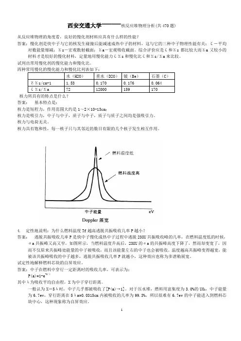
西安交通大学——核反应堆物理分析(共470题)从反应堆物理的角度看,良好的慢化剂材料应具有什么样的性能?答案:慢化剂是快中子与它的核发生碰撞后能减速成热中子的材料,这与它的三种中子物理性能有关:δ-平均对数能量缩减;Σs-宏观散射截面;Σa-宏观吸收截面。
综合评价应是δ和Σs都比较大而Σa又较小的材料才是较好的慢化材料,定量地用慢化能力δΣs和慢化比δ和Σs/Σa来比较。
试列出常用慢化剂的慢化能力和慢化比。
核力所具有的特点是什么?答案:基本特点是:核力是短程力,作用范围大约是1~2×10-13cm;核力是吸引力,中子与中子,质子与中子,质子与质子之间均是强吸引力。
核力与电荷无关。
核力具有饱和性,每一核子只与其邻近的数目有限的几个核子发生相互作用。
4. 定性地说明:为什么燃料温度Tf越高逃脱共振吸收几率P越小?答案:逃脱共振吸收几率P是快中子慢化成热中子过程中逃脱238U共振吸收峰的几率,在燃料温度低的时候,ζa共振峰又高又窄,如图所示,当燃料温度升高后,238U的ζa的共振峰高度下降了,然而却变宽了,因而不仅原来共振峰处能量的中子被吸收,而且该能量左右的中子也会被吸收。
温度越高共振峰变得越宽,能被该共振峰吸收的中子越多,逃脱共振吸收几率P就越小,这种效应也称为多谱勒展宽。
试定性地解释燃料芯块的自屏效应。
答案:中子在燃料中穿行一定距离时的吸收几率,可表示为:P(a)=1-e-X/λ其中λ为吸收平均自由程,X为中子穿行距离。
一般认为X=5λ时,中子几乎都被吸收了[P(a)→1]。
对于压水堆,燃料用富集度为3.0%的UO2,中子能量为6.7ev,穿行距离在5λa=0.0315cm内被吸收的几率为99.3%,所以很难有6.7ev的中子能进入到燃料芯块中心,这种现象称为自屏效应。
6. 什么是过渡周期?什么是渐近周期?答案:在零功率时,当阶跃输入-正反应性ρ0(ρ0<β)后,反应堆功率的上升速率(或周期)是随ρ0输入后的时间t而改变的(如图所示)。

a r X i v :h e p -p h /0510277v 2 13 J a n 2006D +sJ (2317)→D +s π0decay widthMarina NielsenInstituto de F´ısica,Universidade de S˜a o Paulo,C.P.66318,05389-970S˜a o Paulo,SP,BrazilWe use the QCD sum rules to analize the hadronic decay D +sJ (2317)→D +s π0,in the hypotesisthat the D +sJ (2317)can be identified as a four-quark state.We use a diquak-antidiquark current and work to the order of m s in full QCD,without relying on 1/m c expansion.We find that the partial decay width of the hadronic isospin violating mode is proportional to the isovector quarkcondensate, 0|¯dd −¯u u |0 .The estimated partial decay width is of the order of 6keV.PACS numbers:11.55.Hx,12.38.Lg ,13.25.-kThe strange-charmed mesons D +sJ (2317)and D +sJ (2460)with spin parity 0+,1+[1,2,3,4]are lighter than the prediction of the very successful quark model for the charmed mesons [5].One interpretation is that this is evidence for a chiral symmetry where the mass gap between the 0−and 1−states equates the mass gap between the 0+and 1+states [6].Other interpretations are related with the underlying structure of these mesons,which has been extensively debated.They have been interpreted as conventional c ¯s states [7,8,9,10,11,12,13,14,15,16],two-meson molecular state [17,18],D −K -mixing [19]or four-quark states [20,21,22,23,24,25,26,27].Because of their low masses,these two states are lower than the DK and D ∗K thresholds.Therefore,their strong decays must proceed through isospin violating effects.There have been some discussions of their decays within the quark model [6,13,14,15,20]and QCD sum rules [16].In all these studies but [14],the isospin violating effects were considered through the η−π0mixing.However,if these mesons are considered as four-quark states,in a QCD sum rule calculation,the isospin violating effects can be introduced through the mass and quark condensate difference between the u and d quarks.In a recent calculation [23]the scalar-isoscalar meson D +sJ (2317)were considered as a S -wave bound state of a diquark-antidiquark pair.As suggested in ref.[28],the diquark was taken to be a spin zero colour anti-triplet.The corresponding interpolating field is:j S =ǫabc ǫdec 2(u T a Cγ5c b )(¯u d γ5C ¯s T e )+(d T a Cγ5c b )(¯d d γ5C ¯s T e) ,(1)where a,b,c,...are colour indices and C is the charge conjugation matrix.In ref.[23],using the QCD sum rule (QCDSR)formalism [29,30,31],it was shown that it is possible to reproduce the experimental mass of the meson D +sJ (2317)using this four-quark state picture.Here,we extend the calculation done in ref.[23]to study the vertexassociated with the decay D +sJ (2317)→D +s π0.The QCDSR calculation for the vertex,D +sJ (2317)D +s π0,centers around the three-point function given byΓµ(p,p ′,q )=d 4xd 4ye ip ′.x e iq.y 0|T [j D s (x )j π05µ(y )j †S (0)]|0 ,(2)where p =p ′+q and the interpolating fields for the pion and D s mesons are given by:j π5µ=12(¯u a γµγ5u a −¯da γµγ5d a ),j D s =i ¯s a γ5c a .(3)The fundamental assumption of the QCD sum rule approach is the principle of duality.Specifically,we assumethat there is an interval over which the above vertex function may be equivalently described at both,the quark level and at the hadron level.Therefore,the underlying procedure of the QCD sum rule technique is the following:on one hand we calculate the vertex function at the quark level in terms of quark and gluon fields.On the other hand,the vertex function is calculated at the hadronic level introducing hadron characteristics such as masses and coupling constants.At the quark level the complex structure of the QCD vacuum leads us to employ the Wilson’s operator product expansion (OPE).The calculation of the phenomenological side proceeds by inserting intermediate states for D s ,π0and D sJ ,and by using the definitions:0|j π05µ|π0(q )=iq µF π,0|j D s |D s (p ′) =m 2D s f D s(m c +m s )(p 2−m 2D sJ )(p ′2−m 2D s )(q 2−m 2π)q µ+continuum contribution ,(5)where the coupling constant g D sJ D s πis defined by the on-mass-shell matrix elementD s π|D sJ =g D sJ D s π.(6)The continuum contribution in Eq.(5)contains the contributions of all possible excited states.For the light scalar mesons,considered as diquark-antidiquark states,the study of their vertices functions using the QCD sum rule approach at the pion pole [11,30,32,33],was done in ref.[34].In Table I we show the results obtained for the different vertices studied in ref.[34],as well as the experimental values.Table I:Numerical results for the coupling constantsvertexg exp (GeV)3.1±0.5κK +π−4.5±0.41.6±0.1f 0π+π−1.6±0.8From Table I we see that,although not exactly in between the experimental error bars,the hadronic couplings determined from the QCD sum rule calculation are consistent with existing experimental data.The biggest discrepancy is for g f 0π+π−and this can be understood since the f 0→π+π−decay is mediated by gluon exchange and,therefore,probably in this case αs corrections,which were not considered,could play an important role.Here,we follow ref.[34]and work at the pion pole.The main reason for working at the pion pole is that the matrix element in Eq.(6)defines the coupling constant only at the pion pole.For q 2=0one would have to replace g D sJ D s π,in Eq.(6),by the form factor g D sJ D s π(q 2)and,therefore,one would have to deal with the complications associated with the extrapolation of the form factor [35,36].The pion pole method consists in neglecting the pion mass in the denominator of Eq.(5)and working at q 2=0.In the OPE side one singles out the leading terms in the operatorproduct expansion of Eq.(2)that match the 1/q 2term.In the phenomenological side,in the structure qµ(m c +m s )(p 2−m 2D sJ )(p ′2−m 2D s )+∞m 2cρcont (p 2,u )s 0−p 2Θ(u −u 0)[37,38],with s 0and u 0being the continuum thresholds for D sJ and D s respectively.Since we are working at q 2=0,we take the limit p 2=p ′2and we apply the Borel transformation to p 2→M 2to get:Γphen(M 2)=λS m 2D s f D s F πg D sJ D s π(s 0−u )du,and ρcc (u )=b (u)where the spectral density,ρOP E ,is given by the imaginary part of the correlation function.Transferring the pure continuum contribution to the OPE side,the sum rule for the coupling constant,up to dimension 7,is given by:C e −m 2D s /M 2−e −m 2D sJ/M2 +A e −s 0/M 2=γ ¯q q 1u2+m c m s u −m c ß12e−m 2c /M 21+m 2c (m c +m s )(m 2D sJ −m 2D s )g D sJ D s π.(12)InEq.(11),γmeasures theisospin symmetrybreaking in the quark condensate:γ=0|¯dd −¯u u |0ss =0.8 ¯q q .For the meson decay constants we use F π=√s 0≤2.8GeV we get λs =(2.9±0.3)×10−3GeV 5.In Fig.1we show,through the dots,the right-hand side (RHS)of Eq.(11),for u 0=6GeV 2and γ=−1×10⁻²[40],as a function of the Borel mass.We use the same Borel window as defined in ref.[23].1 1.21.4 1.61.82M 2(GeV 2)2e−074e−076e−078e−07R H S X L H S (G e V 7)FIG.1:Dots:the RHS of Eq.(11),as a function of the Borel mass.The solid line gives the fit of the QCDSR results through the LHS of Eq.(11).To determine g D sJ D s πwe fit the QCDSR results with the analytical expression in the left-hand side (LHS)of Eq.(11):C e −m 2D s /M 2−e −m 2D sJ /M 2 +A e −s 0/M 2,(14)and we get (using√s 0=2.7GeV)we get g D sJ D s π=50MeV.Allowings 0to vary in the interval 2.6≤√s 0=2.7GeV and varying the quark condensate,the charm quark and the strange quark masses in theintervals:−(0.24)3≤ ¯q q ≤−(0.22)3GeV 3,1.1≤m c ≤1.3GeV and 0.11≤m s ≤0.15GeV,we get results for the coupling constant still between the lower and upper limits given above.However,varying the value of γform −1×10⁻²to the more recent value given in [41]:γ=−2.6×10⁻²,and keeping the other parameters fixed we get g D sJ D s π=130MeV.On the other hand,if we use the smallest (in module)value allowed for γ:γ=−2.×10−3,we get g D sJ D s π=10MeV.Therefore,the biggest source of uncertainty in our calculation is the value of γ.In all cases considered here,the quality of the fit between the LHS and the RHS of Eq.(11)is similar to the one shown in Fig.1.The coupling constant,g D sJ D s π,is related with the partial decay width through the relation:Γ(D +sJ (2317)→D +s π0)=1λ(m 2D sJ ,m 2D s ,m 2π),(15)where λ(a,b,c )=a 2+b 2+c 2−2ab −2ac −2bc .Considering γ=−1×10⁻²,which was the value found in [40]tobe consistent with the neutron-proton mass difference in a QCDSR calculation,and allowing ¯q q ,m c ,m s and s 0to vary in the ranges discussed above we get:Γ(D +sJ (2317)→D +s π0)=(6±2)keV .(16)However,it is important to state that,if the value for γfound in ref.[41]proves to be correct,then the partial decay width could be as large as Γ(D +sJ (2317)→D +s π0)∼40keV,in agreement with the QCDSR calculation done inref.[16],where the meson D +sJ (2317)is considered as a ordinary c ¯s state.In Table II we show the partial decay width obtained by different theoretical groups.The first five calculationsassume a c ¯s picture for D +sJ (2317),while the last two assume a four-quark picture for it.Table II:The decay width Γ(D +sJ (2317)→D +s π0)from various theoretical approaches.ref.[13][15][20]Γ(keV)7±11610−1000|¯u u |0,which measures the isospin symmetry breaking in thequark condensate.Since,in our approach,the partial decay width is directly proportional to γ2,and since there is a large uncertainty in the value of γ,considering γin the range −2.6×10⁻²≤γ≤−2×10⁻³we get the partial decaywidth in the range 0.2keV ≤Γ(D +sJ (2317)→D +s π0)≤40keV.However,from other QCDSR calculation,we believethat the value of γis ∼−1×10⁻²,which gives the result shown in Eq.(16).As a final remark we would like to point out that if,instead of using a isoscalar current,we have used a isovector current for D sJ (2317)(as suggested in ref.[27]),the difference in Eq.(11)would be a factor 2in the place of γ.In this case the decay would be isospin allowed and the partial width would be ∼230MeV,much bigger than the experimental upper limit to the total width Γ∼5MeV.Acknowledgements[5]S.Godfrey and N.Isgur,Phys.Rev.D32,189(1985);S.Godfrey and R.Kokoshi,Phys.Rev.D43,1679(1991).[6]W.Bardeen,E.Eichten and C.Hill,Phys.Rev.D68,054024(2003).[7]Y.-B.Dai,C.-S.Huang,C.Liu and S.-L.Zhu,Phys.Rev.D68,114011(2003).[8]G.S.Bali,Phys.Rev.D68,071501(R)(2003).[9]A.Dougall,R.D.Kenway,C.M.Maynard and C.Mc-Neile,Phys.Lett.B569,41(2003).[10]A.Hayashigaki and K.Terasaki,hep-ph/0411285.[11]S.Narison,Phys.Lett.B605,319(2005).[12]A.Deandrea,G.Nardulli and A.Polosa,Phys.Rev.D68,097501(2003).[13]P.Colangelo and F.De Fazio,Phys.Lett.B570,180(2003).[14]S.Godfrey,Phys.Lett.B568,254(2003).[15]Fayyazuddin and Riazuddin,Phys.Rev.D69,114008(2004).[16]W.Wei,P.-Z.Huang and S.-L.Zhu,hep-ph/0510039.[17]T.Barnes,F.E.Close and H.J.Lipkin,Phys.Rev.D68,054006(2003).[18]A.P.Szczepaniak,Phys.Lett.B567,23(2003).[19]E.van Beveren and G.Rupp,Phys.Rev.Lett.91,012003(2003).[20]H.-Y.Cheng and W.-S.Hou,Phys.Lett.B566,193(2003).[21]K.Terasaki,Phys.Rev.D68,011501(R)(2003).[22]L.Maiani,F.Piccinini,A.D.Polosa,V.Riquer,Phys.Rev.D71,014028(2005).[23]M.E.Bracco et al.,Phys.Lett.B624,217(2005).[24]H.Kim and Y.Oh,hep-ph/0508251.[25]T.Browder,S.Pakvasa and A.A.Petrov,Phys.Lett.B578,365(2004).[26]U.Dmitrasinovic,Phys.Rev.D70,096011(2004);Phys.Rev.Lett.94,162002(2005).[27]A.Hayashigaki and K.Terasaki,hep-ph/0410393.[28]R.L.Jaffe and F.Wilczek,Phys.Rev.Lett.91,232003(2003).[29]M.A.Shifman,A.I.and Vainshtein and V.I.Zakharov,Nucl.Phys.B147,385(1979).[30]L.J.Reinders,H.Rubinstein and S.Yazaky,Phys.Rep.127,1(1985).[31]B.L.Ioffe,Nucl.Phys.B188,317(1981);B191,591(E)(1981).[32]S.Narison,Spectral Sum Rules,World Scientific Lecture Notes in Physics26.[33]M.E.Bracco,F.S.Navarra,M.Nielsen,Phys.Lett.B454,346(1999).[34]T.V.Brito,F.S.Navarra,M.Nielsen,M.E.Bracco,Phys.Lett.B608,69(2005).[35]M.E.Bracco et al.,Phys.Lett.B521,1(2001).[36]H.G.Dosch,E.M.Ferreira,F.S.Navarra and M.Nielsen,Phys.Rev.D65,114002(2002).[37]B.L.Ioffe and A.V.Smilga,Nucl.Phys.B232,109(1984).[38]M.Eidem´u ller et al.,Phys.Rev.D72,034003(2005).[39]J.Gasser,H.Leutwyler,Nucl.Phys..B250,465(1985).[40]X.Jin,M.Nielsen,J.Pasupathy,Phys.Rev.D51,3688(1995);H.Forkel,M.Nielsen,Phys.Rev.D55,1471(1997),andreferences therein.[41]H.-C.Kim,M.M.Musakhanov,M.Siddikov,hep-ph/0508211.[42]I.Bediaga,M.Nielsen,Phys.Rev.D68,036001(2003).。
公开中物院中子物理学重点实验室2013年度课题指南中国工程物理研究院中子物理学重点实验室中国工程物理研究院核物理与化学研究所2013年4月中国工程物理研究院中子物理学重点实验室目录一、概述 (1)二、重点课题 (1)三、一般课题 (5)四、概念研究课题 (10)五、培育课题 (13)六、说明 (15)附件1:课题管理办法附件2:课题申请书附件3:月度进展表中物院中子物理学重点实验室2013年度课题指南一、概述中物院中子物理学重点实验室(以下简称“实验室”)于2012年3月经我院批准、2012年5月挂牌进入试运行阶段,其挂靠单位为中物院核物理与化学研究所。
实验室着重面向核武器研发及战略科技任务中中子物理学方面的科学问题,通过开展前沿性、创新性的基础及应用基础研究,加强对外合作交流,与院外科学技术基础创新实现高效联接,推动中子物理学学科方向的发展。
实验室的研究工作主要面向三个研究领域:中子学参数、中子应用技术、中子源及射线探测技术三个。
为推动中子物理学界的开放和交流,实验室设立本年度实验室拟支持的研究课题包括:1 重点课题:原则上,研究周期为三年,总支持经费为100万~200万元,定向发布。
2 一般课题:原则上,研究周期为两年,总支持经费为30万~60万元,定向发布。
3 概念研究课题:原则上,研究周期一年,总支持经费为5万~10万元,定向发布。
4 培育课题:请参看本指南第五部分。
二、重点课题课题1.1: 重要裂变核素裂变瞬发中子谱测量技术研究所属方向:中子学参数研究目标: 以反应堆热中子源和加速器中子源为实验平台,开展中子诱发裂变瞬发高能中子谱测量技术研究,获得能量范围1∼10MeV的裂变瞬发中子能谱,能谱的不确定度:1MeV∼4MeV为7%,4MeV∼7MeV为7%∼15%,7MeV∼10MeV为15%∼25%。
研究内容:物理建模、数值模拟,为实验研究提供必要的参考;实验布局的优化,包括中子源的准直屏蔽系统、探测器屏蔽装置以及实验系统布局;开展探测系统、信号采集系统建立;在D-T中子源条件下,开展脉冲或直流模式下的三重符合测量技术研究,非裂变中子甄别技术研究;进行探测器的能量刻度和飞行时间谱的时间刻度,中子探测器和α探测器的效率标定;开展在堆热中子和D-T中子作用下裂变瞬发中子能谱测量实验研究;实验数据的处理。
Pan Pearl River Delta Physics Olympiad 20132013年泛珠三角及中华名校物理奥林匹克邀请赛Sponsored by Institute for Advanced Study, HKUST香港科技大学高等研究院赞助Part-1 (Total 5 Problems) 卷-1(共5题)(9:00 am – 12:00 pm, Feb. 15, 2013)Q1 (9 points)A bead of mass m and initial speed v 0 hits a uniform thin rod of mass m and lengthL perpendicularly at one end, which initially rests on a horizontal plane.a) If the other end of the rod is fixed on a hinge which allows the rod to rotatefreely in the horizontal plane, and the bead stays on the rod after collision, find the mechanicalenergy loss due to the collision.b) If the rod is free to move on the plane and the bead stays on the rod after collision, find themechanical energy loss due to the collision.c) The rod is free to move on the plane. The collision is elastic. The velocity of the bead isperpendicular to the rod right after the collision. Find the angular speed of the rod, and the speeds ofthe bead and the center of mass of the rod.第一题 (9分)一质量为m 的小球以初速度0v 垂直撞击一个质量同为m 长度为L 的均匀细杆端点。
a r X i v :h e p -e x /9803014v 2 18 M a r 1998K2K (KEK to Kamioka)neutrino-oscillation experiment atKEK-PS ∗)Yuichi Oyama ∗∗)for K2K collaboration∗∗∗)Institute of Particles and Nuclear Studies,High Energy Accelerator Research Organization,Tsukuba,Ibaraki 305-0801JapanA long-baseline neutrino-oscillation experiment using a well-defined neutrino beam is in preparation at KEK.Neutrinos generated at KEK will be detected by the Super-Kamiokande detector 250km away.The design of the neutrino beam line,beam monitors and detector are briefly presented.The sensitivities for neutrino oscillations are also discussed.§1.OverviewIn recent years,several underground neutrino observatories 1)-3)have reported that the atmospheric neutrino ratio,R ≡(νµ+¯νµ)/(νe +¯νe ),is significantly smaller than the theoretical expectations.This “atmospheric neutrino anomaly”can be explained by a neutrino oscillation hypothesis with an oscillation parameter region of ∆m 2∼10−2eV 2and sin 22θ∼1.The atmospheric neutrino anomaly has also been confirmed by a preliminary result from the Super-Kamiokande experiment,4),which shows a rather smaller ∆m 2than does Kamiokande.The K2K experiment 5)(formerly called the KEK-PS E362experiment)is the first long-baseline neutrino-oscillation experiment using an artificial neutrino beam.The almost pure νµbeam from π+decays is generated in the KEK 12-GeV Proton Synchrotron,and is directed toward the Super-Kamiokande detector,which is about 250km away from KEK.The neutrino events observed in the Super-Kamiokande detector are compared with neutrino events in the front detector constructed at the KEK site.The nominal sensitive region on the neutrino-oscillation parameter is ∆m 2=10−2eV 2∼10−3eV 2,which covers the parameter region suggested by the atmospheric neutrino anomaly.§2.Neutrino beamA neutrino beamline is under construction at KEK.6)A picture of the neutrino beamline under construction is shown in Figure 1.A proton beam of 12GeV is extracted from the Proton Synchrotron with a fastFig.1.Neutrino beamline under construction(November19th,1997). extraction mode.The time width of one spill is1.1µsec.The frequency of the beam is1spill per2.2seconds and the nominal intensity is about6×1012protons/spill.A total of1×1020p.o.t(protons on target)will be extracted in3years of operation.The proton beam is bent by94◦by dipole magnets,and transported to an aluminum target of2cmφ×65cm.Positively charged particles produced in the target are focused by a toroidal magneticfield produced by a pair of Horns7)toward the direction of the Super-Kamiokande detector.The nominal pulse current of the Horn is250kA.The muon neutrinoflux will be enhanced by a factor of14by installing the Horns.A test operation of the Horns was successfully completed in fall,1997.In a200m decay tunnel followed with the Horn magnets,oneπ+decays to oneνµand oneµ+.Muons and the remaining pions are absorbed in a beam dump downstream of the decay tunnel.The generation of the neutrino beam is simulated using a Monte-Carlo simula-tion.The energy spectrum and angular dependence of the beam at the front detector (300m downstream from the target)and at the Super-Kamiokande detector(250km downstream)are shown in Figure2.The mean energy of the neutrino beam is about 1.4GeV,and the peak energy is about1GeV.The contamination of electron neu-trinos was calculated to be∼1%.The energy spectrum of the neutrino beam is uniform within an angular spread of3mrad from the center of the beam axis.Be-cause the angular acceptance of the Super-Kamiokande detector from the KEK site is∼50m/250km=0.2mrad,the divergence of the neutrino beam is much larger than the size of the Super-Kamiokande detector.§3.Beam monitorsIn order to obtain the neutrino-energy spectrum,a pion monitor8)will be set downstream of the second Horn.The pion monitor is a gas Cherenkov detector with a1010101010E ν (GeV)N ν (/c m 2/0.1G e V )1010101010E ν (GeV)N ν (/c m 2/0.1G e V )r (cm)r (km)Fig.2.Expected energy spectrum and radial distribution for 1020protons on the target (corre-sponding to 3years of operation),both at the front detector (L =300m)and Super-Kamiokande (L =250km).spherical mirror and R-C318gas.Charged pions emit Cherenkov light in the gas,and a Cherenkov ring is created in the focus plane.The light intensity of the Cherenkov light is monitored by ADC on a spill-by-spill basis.The information concerning the Cherenkov-light intensity and shape of the ring are used to calculate the momentum distribution and divergence of the pion beam.The ratio of neutrino flux at the front detector and at Super-Kamiokande site can be expected for a neutrino energy larger than 1.0GeV based on the decay kinematics of the pions.A muon monitor will be installed downstream of the decay tunnel.The muon monitor is a 2m ×2m pad-type ionization chamber filled with He gas.The an-ode current induced by the muon beam is read out from the x-direction and the y-direction with an interval of 5cm.The 2-dimensional projection of the muon intensity provides information about the beam profile.The position of the beam center is obtained with an accuracy of ∼2cm.§4.Front detectorThe front detector in the KEK site is located 300m downstream of the target.A schematic view of the front detector is shown in Figure 3.We will constructSide ViewRun555 event 1---------------------------------------Enu = 3.65---------------------------------------6: ( .39 -.49 3.34 ) 3.4014: ( -.46 .39 .48 ) 1.221: ( .00 .00 .00 ) .011: ( .00 .00 .00 ) .00---------------------------------------Fig.4.Cross-sectional view of a typical quasi-elastic scattering event in the Fine-Grained Detector obtained from a Monte-Carlo simulationments are aligned.The absolute time of an event is obtained by plastic scintillators with an accuracy of0.7nsec.This information is used to reject cosmic-ray muon background with a reduction rate of∼99%,and is used in the time correction of the muon chamber data.Neutrino interactions outside of the Fine-Grained Detector can also be identified by the counter.The purpose of the lead-glass counters is to precisely measure the contamination of electron neutrinos in the muon neutrino beam.It consists of600lead-glass coun-ters;each counter is12cm×12cm in acceptance.The basic idea of the electronidentification is based on the response of the lead-glass counters to muons and elec-√trons.The energy deposit of electron can be measured with a resolution of8%/Table I.Summary of the detector performance in the K2K experiment.detector detectorKamiokande8∼10%3%∆θµ∼1%∼10%3%∆E e /E eE e3%/√E eTable II.Number of neutrino interactions in the fiducial volume.detector detector Kamiokande 5.8ton21ton22500ton(dimension)3.0×10¹²/cm 23.0×10¹²/cm 22.3×10⁶/cm 2event rate171600552000465(quasi-elastic)125040004is shown in Figure 4.A detailed description of the Super-Kamiokande,which will be used as a far detector,has been made,4),10)and is not presented here.The performance of the 1kt water Cherenkov detector,Fine-Grained Detector and Super-Kamiokande are summarized in Table.I.Number of neutrino events ex-pected in the fiducial volume are also shown in Table.II.§5.SensitivityAn examination of the νe ↔νµoscillation in K2K is an appearance search.Any small contamination of νe in the νµbeam can be confirmed by the lead-glass counter.An excellent particle-identification capability in the Super-Kamiokande detector was already examined.9)Therefore,a possible excess of electron neutrino events in the Super-Kamiokande detector is direct evidence of the neutrino oscillation.Although there is a possible background of π0from a neutral-current interaction of νµ,it can be easily recognized,because most of the π0have an energy of less than 1.0GeV.If the oscillation parameters,(∆m 2,sin 22θ)=(1×10−2,1),are assumed,the number of electron events with E e >1.5GeV is expected to be ∼90,whereas the background from π0and from νe contamination is only ∼4.The νµ↔ντoscillation can be examined by studying any distortion of the neutrino energy spectrum at Super-Kamiokande.The expected neutrino energy spectrum at given neutrino oscillation parameters is shown in Figure 5.The change in the neutrino energy spectrum as well as a reduction of neutrino events wouldFig.5.Expectedνµenergy spectra with Super-Kamiokande at1020protons on target for various νµ↔ντoscillation parameters(a)-(d)(data points with error bars)and for the no oscillations (solid histogram).comprise an evidence of neutrino oscillation.In the determination of the neutrino energy spectrum,we will employ a quasi-elastic interaction of muon neutrinos,because quasi-elastic scattering is recognized as single ring events in the Super-Kamiokande detector,and because the energy of the neutrinos can be calculated from the momentum and the scattering angle of the muon track.It should also be noted that the cross section of quasi-elastic scattering is well understood compared with that of other interactions.The sensitivity of theνe↔νµandνµ↔ντoscillation in K2K is shown in Figure6together with other experiments1),4),11)-20)which are proposed,under construction,in data taking,orfinished.The sensitive parameter regions in K2K are∆m2>∼1×10⁻³eV2and sin22θ>0.1for theνe↔νµoscillation,and∆m2>∼3×10⁻³eV2and sin22θ>0.4for theνµ↔ντoscillation.Thefirst neutrino beam in K2K will be available in January,1999.References1)K.S.Hirata et al.,Phys.Lett.B205,416(1988);K.S.Hirata et al.,Phys.Lett.B280,146(1992);E.W.Beier et al.,Phys.Lett.B283,446(1992);Y.Fukuda et al.,Phys.Lett.B335,237(1994).2) D.Casper et al.,Phys.Rev.Lett.66,2561(1991);R.Becker-Szendy et al.,Phys.Rev.D46,3720(1992).3)W.W.M.Allison et al.,Phys.Lett.B391,491(1997).4)Y.Totsuka,in Proceedings of18th International Symposium on Lepton Photon Interac-10-410-310-210-1100.20.40.60.81∆m 2(e V 2)sin 2(2θ)νµ→νx90%C.L.K2KCDHSCHARM MINOSKamiokandesub-GeV + multi-GeVSuper-Kamiokandepreliminary 400dayssub-GeV + multi-GeV, P.C.10-410-310-210-1100.20.40.60.81∆m 2(e V 2)sin 2(2θ)νµ→νe90%C.L.K2KE776KARMENBugeyKrasnoyarsk CHOOZMINOSKamiokandeLSNDsub-GeV + multi-GeV(a)(b)Fig.6.Exclusion contours of 90%C.L.for (a)νµ↔ντoscillation and (b)νe ↔νµoscillation(thick solid lines).The allowed regions by Kamiokande,1)LSND 17)and Super-Kamiokande 4)and excluded (or sensitive)regions by other experiments are also plotted.11)-20).tions,Hamburg,July 1997.5)K.Nishikawa et al.,E362KWK-PS proposal,March,1995;Nucl.Phys.B (Proc.Suppl.)59,289(1997)6)H.Noumi et al.,Nucl.Instrum.Meth.A398,399(1997)7)Y.Yamanoi et al.,“Large Horn Magnets at KEK neutrino beam line”,KEK Preprint 97-225,November 1997.8)T.Inagaki,Master thesis,Univ.of Tokyo,1998(in Japanese).9)S.Kasuga et al.,Phys.Lett.B374,238(1996).10)Nishijima,in these proceedings.11) F.Dydak et al.(CDHS collaboration),Phys.Lett.B134,281(1984).12) F.Bergsma et al.(CHARM collaboration),Z.Phys.C40,171(1988).13)MINOS collaboration,“P-875:A long baseline neutrino oscillation experiment at Fermi-lab”,NuMI-L-63,Feb.1995.14)L.Borodovsky et al.(E776collaboration),Phys.Rev.Lett.68,274(1992).15)G.S.Vidyakin et al.(Krasnoyarsk collaboration),JETP Lett.59,390(1994).16) B.Achkar et al.(Bugey collaboration),Nucl.Phys.B434,503(1995).17) C.Athanassopoulos et al.(LSND collaboration),Phys.Rev.Lett.75,2650(1995);C.Athanassopoulos et al.(LSND collaboration),Phys.Rev.Lett.77,3082(1997).18) B.Armbruster et al.(KARMEN collaboration),Nucl.Phys.B(Proc.Suppl.)38,235(1995).19)G.Zacek et al.(Gosgen collaboration),Phys.Rev.D34,2621(1996).20)M.Apollonio et al.(Chooz collaboration),HEP/EX/9711002,November,1997.。
arXiv:0809.5076v1 [hep-ph] 29 Sep 2008NUHEP-TH/08-05LightSterileNeutrinoEffectsatθ13-SensitiveReactorNeutrinoExperimentsAndr´edeGouvˆeaandThomasWytockNorthwesternUniversity,DepartmentofPhysics&Astronomy,2145SheridanRoad,Evanston,IL60208,USA
Westudytheimpactofverylightsterileneutrinos(∆m2new∈[1,10]×10−2eV2,sin22θnew<10−1)onupcomingθ13-drivenreactorantineutrinoexperimentslikeDouble-CHOOZandDayaBay.Oscillationsdrivenbythesevalesof∆m2newaffectdatainthenearandfardetectorsdifferentlyandhencepotentiallymodifythecapabilityoftheseexperimentalsetupstoconstrainandmeasuresin22θ13.Wefindthatthehypothesisθnew=0negativelyimpactsone’sabilitytoeitherplaceanupperboundonsin22θ13intheadventofnooscillationsignalormeasuresin22θ13ifaθ13-drivensignalisobserved.Theimpactofsterileneutrinoeffects,however,dependssignificantlyonone’sabilitytomeasuretherecoilpositronenergyspectrum.Ifsin22θnew>∼10−2,upcomingθ13-drivenreactorantineutrinoexperimentsshouldbeabletomeasuresin22θnewand∆m2new,alongwithsin22θ13,aslongasoneissensitivetodistortionsintherecoilpositronenergyspectruminthenear(andfar)detectors.
I.INTRODUCTIONNext-generationreactorantineutrinoexperimentsarecurrentlyunderconstruction(fordetailsonconcreteprojectssee[1,2]).Guidedbytheresultsofcurrentneutrinooscillationexperiments[3],theseareaimedatobservingelectronantineutrinodisappearancedrivenbythe“atmospheric”mass-squareddifference,∆m213,andhencemeasuringthestillelusiveθ13mixingangle(cf.Sec.II).Inordertosignificantlyimproveonpreviousreactorantineutrinoexperiments,next-generationexperimentswillmakeuseofatwo-detectorsetup.Afardetectoristobeplacedanoptimaldistanceawayfromthereactorcoresoastomaximizeθ13-drivenelectronantineutrinodisappearance,whileaneardetectorisplacedclosetothereactorcoreinordertomeasurethe“unoscillated”electronantineutrinoflux.Assumingdifferencesbetweennearandfardetectorsareunderstoodatthefewpermillelevelandthatenoughstatisticsareaccumulated,oneultimatelyaimsatbeingsensitivetosin22θ13valuesaround1%.Thesetupsummarizedabovereliesontheassumptionthatallneutrinooscillationphenomenaareproperlydescribedintermsofthreemassiveneutrinoswhichinteractunderthewell-knownweakinteractions.Currentdatarevealthistobeanexcellentassumption,butthepossibilityofother“subleading”effectsremains.Here,weconsiderthepossibilitythatlightsterileneutrinosmixslightlywithactiveneutrinosandhencemodifythestandardneutrinooscillationpicture.Sterileneutrinos—gaugesingletfermions—areamongthesimplestextensionsofthestandardmodelofparticlephysics.Theymaybeanintegralpartofthephysicsresponsibleforneutrinomasses[4,5],andmaybeacomponentofthedarkmatterintheUniverse[6].Theoreticallyspeaking,nothingisknownaboutsterileneutrinomasses,andverylightsterileneutrinos(saymν≪1keV)areasnatural(asdefinedby’tHooft)asveryheavyones(saymν≫1010GeV).Experiments,therefore,providealmostalltheunbiasedinformationwehaveregardingsterileneutrinomasses.WebrieflydiscussexperimentalconstraintsinSec.II.Weconcentrateonsterileneutrinosthatcouldqualitativelyaffecttheinterpretationofθ13-drivenreactorneutrinoexperiments.Wefindthatthiscanhappenforverylightsterileneutrinosthatintroducetothethree-neutrino-oscillationpictureanewmass-squareddifferenceoforder(1−10)×10−2eV2.Forexample,the“hypotheticalpresence”ofsuchsterilestateshinderstheabilityoftheseexperimentstoruleoutcertainvaluesofθ13ifnoevidenceforoscillationsisobserved.Ontheotherhand,smallsterileneutrinoeffects,ifpresent,mayleadtoverysignificantoscillatoryeffectsintheneardetectoreveninthelimitofvanishingθ13.DetailedresultsarepresentedinSec.III,alongwithastudyofhowwellθ13andsterilemixingparameterscanbesimultaneouslymeasuredwithnext-generationreactorneutrinodata.Beforeproceeding,we’dliketohighlightourgoalsandthelimitationsofouranalysis.Weareinterestedindiscussingthefactthatsterileneutrinoscansignificantlyaltertheinterpretationofthecomparisonbetweennearandfardetectordatainreactorantineutrinoexperiments.Wewouldalsoliketopointoutthattheneardetector—becauseitisexpectedtocollecthundredsofthousandsofneutrinoscatteringevents—mayplayanactiveroleinrevealingnew,unexpectedphysics.Withthisinmind,oursimulations,discussedinmoredetailinSec.III,arenotaimedatrealisticallydescribingexperimentalsetupsorquantitativelygaugingtheircapabilities.Qualitatively,however,webelievethatalloftheeffectsdiscussedinthismanuscriptwillmanifestthemselvesoncerealexperimentaldataisanalyzed.Ourmainmessage,alongwithourresults,issummarizedinSec.IV.