Directional solidi?cation of TiAl-base alloys
M.Yamaguchi a,*,D.R.Johnson b ,H.N.Lee c ,H.Inui a
a
Department of Materials Science and Engineering,Kyoto University,Kyoto 606-8501,Japan
b
School of Materials Engineering,Purdue University,1289MSEE Building,West Lafayette,IN 47907-1289,USA
c
Department of Materials Science and Engineering,KAIST,Taejon 305-701,South Korea
Abstract
Mechanical properties of the lamellar microstructure of TiAl-base alloys are extremely anisotropic with respect to the lamellar orientation.However,if the lamellar microstructure can be aligned parallel to the growth direction,the resulting material should possess a good combination of strength and ductility.Unfortunately,simple casting operations often lead to a solidi?cation tex-ture with the lamellar boundaries all perpendicular to the heat ˉow direction.This di culty can be overcome by directionally solidifying TiAl-base alloys.We have been performing directional solidi?cation experiments with and without using a seeding technique.The current status of directional solidi?cation of TiAl-base alloys is reviewed.#2000Elsevier Science Ltd.All rights reserved.
Keywords:A.Titanium aluminides,based on TiAl;B.Texture;C.Crystal growth;D.Microstructure
1.Introduction
Mechanical properties of the lamellar microstructure in TiAl-base alloys depend on the lamellar orientation with respect to the loading axis.A new approach for studying mechanical properties of the lamellar micro-structure of TiAl-base alloys was introduced in 1990by producing crystals where the entire ingot consists of only a single lamellar grain [1]and thus it is in a sense a single crystal of the fully lamellar polycrystalline alloy.Since numerous thin twin-related lamellae are contained in the major constituent g phase,these crystals were named polysynthetically twinned (PST)crystals [1]from analogy with the phenomenon,``polysynthetic twinning''which is often observed in mineral crystals [2].Since then,lamellar microstructural features and fundamental properties of the lamellar microstructure such as micro-structural characterization,deformation,fracture toughness and macroscopic ˉow behavior have all been extensively studied by making the best of use of PST crystals (for a review see Ref.[3]).
What the studies using PST crystals have typically clari?ed is the e ect of lamellar orientation on the mechanical properties [4]and the anisotropic macro-scopic ˉow behavior of the lamellar microstructural
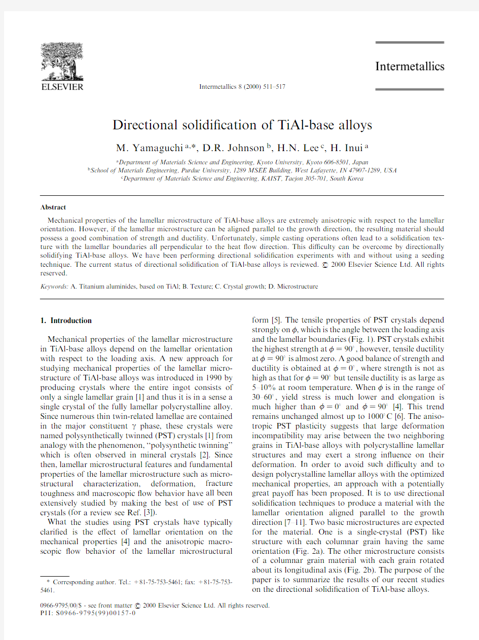
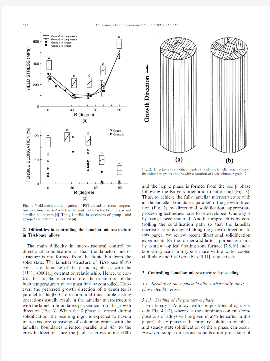
form [5].The tensile properties of PST crystals depend strongly on 0,which is the angle between the loading axis and the lamellar boundaries (Fig.1).PST crystals exhibit the highest strength at 0 90 ,however,tensile ductility at 0 90 is almost zero.A good balance of strength and ductility is obtained at 0 0 ,where strength is not as high as that for 0 90 but tensile ductility is as large as 5±10%at room temperature.When 0is in the range of 30±60 ,yield stress is much lower and elongation is much higher than 0 0 and 0 90 [4].This trend remains unchanged almost up to 1000 C [6].The aniso-tropic PST plasticity suggests that large deformation incompatibility may arise between the two neighboring grains in TiAl-base alloys with polycrystalline lamellar structures and may exert a strong inˉuence on their deformation.In order to avoid such di culty and to design polycrystalline lamellar alloys with the optimized mechanical properties,an approach with a potentially great payo has been proposed.It is to use directional solidi?cation techniques to produce a material with the lamellar orientation aligned parallel to the growth direction [7±11].Two basic microstructures are expected for the material.One is a single-crystal (PST)like structure with each columnar grain having the same orientation (Fig.2a).The other microstructure consists of a columnar grain material with each grain rotated about its longitudinal axis (Fig.2b).The purpose of the paper is to summarize the results of our recent studies on the directional solidi?cation of TiAl-base alloys.
0966-9795/00/$-see front matter #2000Elsevier Science Ltd.All rights reserved.P I I:S 0966-9795(99)00157-
Intermetallics 8(2000)511±517
*Corresponding author.Tel.:+81-75-753-5461;fax:+81-75-753-5461.
2.Di culties in controlling the lamellar microstructure in TiAl-base alloys
The main di culty in microstructural control by directional solidi?cation is that the lamellar micro-structure is not formed from the liquid but from the solid state.The lamellar structure of TiAl-base alloys consists of lamellae of the and 2phases with the (111)g //(0001)a 2orientation relationship.Hence,to con-trol the lamellar microstructure,the orientation of the high temperature a phase must ?rst be controlled.How-ever,the preferred growth direction of a dendrites is parallel to the [0001]direction,and thus simple casting operations usually result in the lamellar microstructure with the lamellar boundaries perpendicular to the growth direction (Fig.3).When the b phase is formed during solidi?cation,the resulting ingot is expected to have a microstructure consisting of columnar grains with the lamellar boundaries oriented parallel and 45 to the growth direction since the b phase grows along h 100i
and the hcp a phase is formed from the bcc b phase following the Burgers orientation relationship (Fig.3).Thus,to achieve the fully lamellar microstructure with all the lamellar boundaries parallel to the growth direc-tion (Fig.2)by directional solidi?cation,appropriate processing techniques have to be developed.One way is by using a seed material.Another approach is by con-trolling the solidi?cation path so that the lamellar microstructure is aligned along the growth direction.In this paper,we review recent directional solidi?cation experiments for the former and latter approaches made by using an optical ˉoating zone furnace [7,8,10]and a laboratory scale ram-type furnace with a water cooled chill plate and CaO crucibles [9,11],respectively.3.Controlling lamellar microstructure by seeding 3.1.Seeding of the phase in alloys where only the phase steadily grows
3.1.1.Seeding of the primary phase
For binary TiAl alloys with compositions of c 2`c `c 3in Fig.4[12],where c is the aluminum content (com-positions of alloys will be given in at%hereafter in this paper),the a phase is the primary solidi?cation phase and steady state solidi?cation of the a phase can occur.However,simple directional solidi?cation processing
of
Fig.1.Yield stress and elongation of PST crystals at room tempera-ture as a function of 0which is the angle between the loading axis and lamellar boundaries [4].The g lamellae in specimens of group-1and group-2are di erently oriented
[4].
Fig.2.Directionally solidi?ed ingots (a)with one lamellar orientation of the columnar grains and (b)with a rotation of each columnar grain [7].
512M.Yamaguchi et al./Intermetallics 8(2000)511±517
TiAl-base alloys within this composition range results in the lamellar microstructure being oriented perpendi-cular to the growth direction because of the preferred growth direction of the a phase.Thus,the lamellar
microstructure in binary TiAl alloys can not be aligned by simple directional solidi?cation processing.To con-trol the orientation of the a phase from the liquid,an appropriately oriented seed crystal can be used.How-ever,the main problem with this approach is ?nding a suitable seed material where the orientation of the a phase can be maintained upon heating.The seed material must meet the following four requirements [7]:
1.The a phase is the primary solidi?cation phase.
2.Upon heating above the a 3a 2+g eutectoid tem-perature,the lamellar microstructure is stable and the a 2phase simply disordered to the a phase.
3.Upon heating,the a phase is thermodynamically stable and the volume fraction of the a phase increases by thickening a lamellae and not by nucle-ating new a lamellae so that the high-temperature a phase has the same orientation as that of the a 2lamellae in the original lamellar microstructure.
4.Upon cooling,the process is reversed and the ori-ginal orientation of the lamellar microstructure is restored.These requirements cannot be met in the binary sys-tem due to the relative position of the a and g phase ?elds in the Ti±Al phase diagram.The composition c 2,which is the lowest Al concentration where the a phase is the primary solidi?cation phase,is richer in Al than c 4.Thus,the g single-phase region is entered during heating for alloys with Al concentrations greater than c 2.As these alloys are heated into the g single-phase region and then g /a two-phase region,new a lamellae with orientations di erent from that in the original lamellar structure can precipitate from the g single-phase matrix.This is because the g phase has four equivalent {111}planes from which the a phase can precipitate.The above four requirements were found to be met in the Ti±Al±Si system for a composition near Ti±43Al±3Si in Fig.5[7].For this composition,the sili-cide phase Ti 5Si 3is present in the microstructure.How-ever,upon heating or cooling,the g +silicide two-phase region is not entered and the lamellar structure was found to be stable up to the temperature at which the a +silicide region is entered.Thus,seeding is
possible,
https://www.doczj.com/doc/e04053488.html,mellar orientations in and
dendrites.
Fig.5.Liquidus surface projected onto the 1100 C isothermal section showing the composition range where the g /a 2lamellar microstructure can be aligned by using a seed material
[7].
Fig.4.The a 2-g portion of the Ti±Al phase diagram [12].
M.Yamaguchi et al./Intermetallics 8(2000)511±517513
since the a phase is stable up to the melting temperature for this composition.When a seed with one orientation is used,ingots of the PST type with a microstructure such as that shown in Fig.2a are https://www.doczj.com/doc/e04053488.html,ually,PST-crystals are grown at a slow growth rate (5mm/h)that produces a planar solid-liquid interface during directional solidi?cation.The result is a high quality PST-crystal with a uniform microstructure.However,directional solidi?cation with a seed material at faster growth rates (20±40mm/h)leads to dendritic solidi?cation.Columnar sub-grains with a slightly di erent lamellar orientation (Fig.2a)are a result of growing a single a -dendrite.
An ingot consisting of two columnar grains with an aligned lamellar structure but di erent lamellar orien-tations was produced using a Ti±43Al±3Si seed with two orientations [7].Thus,an ingot with a microstructure such as that shown in Fig.2b should be able to be pro-duced if an appropriate seed consisting of lamellar grains with an aligned lamellar microstructure and a rotation of each lamellar grain is available.In fact,an ingot with a microstructure close to that of Fig.2b was recently produced by using a seed cut from a Ti±43Al±3Si ingot cast into a metal mould (Fig.6)[13].
3.1.2.Seeding of the phase in alloys where the nucleation of the primary phase can be suppressed
For binary TiAl alloys less than $49at%Al,the b phase is the primary solidi?cation phase.However,for a single pass zone melting case,assuming a planar solid-liquid interface,steady state growth of the a phase can occur for hyper-peritectic compositions of c 1`c `c 2in Fig.4.For this case,the b phase is the primary solidi?-cation phase but,once the peritectic temperature is reached,the a phase will nucleate,covering the b phase,and thus e ectively stopping the peritectic reaction.After steady state growth conditions are reached for the a phase,the steady state growth of a phase can occur as
if it were the primary solidi?cation phase and a PST crystal is formed if only a single a grain exits.However,the exact orientation of the a phase and therefore the orientation of the resulting lamellar microstructure can not be precisely controlled because the b phase was initially nucleated [8].At faster growth rates where dendritic solidi?cation of the a phase occurs,the lamel-lar microstructure tends to be oriented perpendicular to the growth direction due to the preferred growth direc-tion of a phase which is parallel to the [0001]direction.This is the reason that in as-cast microstructures,the lamellar boundaries are usually perpendicular to the dendritic growth direction.
Directionally solidi?ed Ti±43Al±3Si ingots exhibit high strength but low ductility even if they have an aligned lamellar microstructure along the growth direction because of the precipitation of Ti 5Si 3particles.Thus,aiming at reducing the amount of silicide pre-cipitates,the seed composition was kept constant and the composition of master ingot was varied for alloys in the TiAl±Si,TiAl±Nb±Si and Ti±Al systems.Although the b phase is the primary solidi?cation phase in these alloys,seeding was found to be possible for alloys with an Al+Si content close to 47at%.However,for alloys with an Al+Si content greater than 47at%seeding was not possible due to the nucleation of the g phase.
The following sequence of events is believed to occur in the composition range where seeding is possible [8].When the composition of the seed and master ingot is di erent,a portion of the seed was always melted ?rst before the master ingot is allowed to come into contact with the liquid to complete the melting zone.Thus,the b phase does not nucleate at the beginning of directional solidi?cation.However,as zone melting precedes,the composition of the molten zone becomes closer to that of the master ingot and the primary b phase would nucleate until the b /a boundary of the liquidus surface was met.As the b /a boundary curve is followed,the a phase would nucleate and the b phase would be absor-bed by the melt.This would continue until the mass fraction of the b phase had decreased to zero.From this point,the solidi?cation path would then leave the boundary curve and proceed across the primary b region.Thus,for this composition,steady state growth conditions for the b phase can be reached.Experimen-tally,the initial nucleation of the primary b phase can be prevented by using the Ti±43Al±3Si seed crystal and the steady state growth conditions for the a phase can be reached,leading to a successful seeding of the stea-dily growing a phase.Ingots with an aligned lamellar microstructure were indeed obtained for various alloys in the TiAl±Si,TiAl±Nb±Si and Ti±Al systems including Ti±47Al and Ti±46.5Al±3Nb±0.5Si alloys [9,10].Fig.7shows a microstructure taken from a Ti±47Al ingot directionally solidi?ed with a Ti±43Al±3Si seed at 40mm/h.The small variation in lamellar
microstructure
Fig.6.Schematic illustration of columnar grains and their lamellar microstructure in a Ti±43Al±3Si ingot cast in a metal mould [13].
514M.Yamaguchi et al./Intermetallics 8(2000)511±517
may be caused by bending of the dendrite arms during solidi?cation.When Al+Si>47at%,after the solidi?ca-tion path leaves the b/a boundary curve,the solidi?cation proceeds on a line running away from the primary a region and the a/g boundary curve of the liquidus sur-face is intersected.Thus,the nucleation of the g phase would interrupt the growth of the a phase,preventing the alignment of the lamellar microstructure[8].
In brief summary,when the initial liquid zone is rich enough in both Al and Si to prevent the nucleation of the b phase,allowing growth of the a phase from the seed,seeding is successfully made.In contrast,when the liquid zone becomes too rich in Al and Si causing the g phase to nucleate,seeding can not be made successfully. The composition of the?rst liquid to freeze must be made rich enough in solute to prevent the nucleation of the b phase.Thus,the liquid should not be highly https://www.doczj.com/doc/e04053488.html,ually a slow initial growth rate of5mm/h is used until steady state growth conditions are reached. Then the growth rate can be increased to20±40mm/h. When the composition of the seed and master ingot is di erent,a longer melting zone is formed and thus great care must be taken to control the liquid zone shape at higher growth rates.
3.1.3.Seeding of the interdendritic phase in alloys where the phase is the primary solidi?cation phase Fig.8a and b show schematic phase diagrams of bin-ary Ti±Al and ternary Ti±Al±M systems over the compo-sition range of interest,where M is a b-stabilizing element such as Mo[14].The most signi?cant di erence between the two phase diagrams is the existence of the L+a+b three-phase region in the ternary phase diagram.If the original orientation of the lamellar microstructure is maintained upon heating,the three-phase region makes seeding of the a phase possible,similarly to the case where the a phase is the primary solidi?cation phase. This is schematically shown in Fig.9.
The b dendrites in Fig.9are expected to grow along [001].However,the experimental results indicate that the lamellar structure of the entire ingot can be aligned along the growth direction.This is probably because the seeded a phase a ects the nucleation of a from b den-drites by unknown mechanisms so that the a phase formed from the b phase has the same orientation as that of the seeded interdendritic a phase.For seeding to be successful,the g single-phase and b+a two-phase ?elds should not be entered upon heating and cooling. If these two regions are entered upon heating,lamellar grains with di erent lamellar orientations are
formed
Fig.7.Microstructure showing variation in orientation of lamellar
microstructure for a Ti±47Al ingot directionally solidi?ed at40mm/h
[8].
Fig.8.Schematic phase diagrams of(a)binary Ti±Al and(b)ternary
Ti±Al±M systems over the composition range of interest[14,15].M is a
b stabilizing
element.
Fig.9.A possible growth morphology for a and b phases during
directional solidi?cation of TiAl-base alloys.
M.Yamaguchi et al./Intermetallics8(2000)511±517515
following the Blackburn and Burgers orientation rela-tionships.Thus,seeding of the interdendritic a phase is possible in the composition range indicated in the tern-ary phase diagram(Fig.8b).In the corresponding composition range in the binary phase diagram(Fig. 8a),PST crystals can be grown at slow growth rates giving rise to a planar solid±liquid interface,but seeding of PST crystals can not be made.
The conditions for seeding of the interdendritic a phase to be successful have been clari?ed.Next,appro-priate seed materials are to be identi?ed.To avoid the liquid zone to be too long,the composition of the seed material is required to be as close as possible to that of the master ingot.The thermal stability of the lamellar microstructure of various alloys based on Ti±46Al con-taining1±2at%Mo has been investigated and some alloys containing a small amount of carbon such as Ti±46Al±1.5Mo±0.2C have been found to possess a lamel-lar microstructure stable up to the temperature where the?rst liquid phase appears and meet the phase dia-gram requirements for seeding[15].Directionally soli-di?ed Ti±46Al±1.5Mo±0.2C ingots with an aligned lamellar microstructure often contain a small amount of the B2phase which seems to be formed in cores of b dendrites.This is indicative of the occurrence of solidi-?cation morphology such as that shown in Fig.9.Ten-sile properties and creep strength of directionally solidi?ed Ti±46Al±1.5Mo±0.2C have been found to be excellent[15].Their microstructure and creep properties will be published elsewhere[16].
Of the TiAl±Mo base alloys whose lamellar micro-structure stability was examined,some have a lamellar microstructure which is stable enough to be used as a seed material but the others do not.The lamellar width of the alloys with a stable lamellar microstructure is increased upon heating but the lamellar structure itself is preserved.However,the lamellar structure of the other alloys is recrystallized and changes into a duplex structure consisting of equiaxed grains.The lamellar stability is often lost by a small change in composition. The lamellar structure of Ti±46Al±1.5Mo±0.2C is stable but its thermal stability is lost by increasing or decreas-ing Al content by1at%or decreasing C content by0.1 at%without changing Mo content[15].However,add-ing Si by less than1at%often dramatically increases the stability of the lamellar microstructure of alloys which is otherwise not stable[16].The mechanism of such compositional dependence of lamellar stability has yet to be clari?ed.
4.Controlling lamellar microstructure without seeding If the interdendritic a phase in Fig.9is aligned with-out seeding,the lamellar structure of the entire ingot can be aligned along the growth direction similarly to the case of seeding of the interdendritic a phase.Recently, a possible processing window where a reasonably well aligned lamellar microstructure can be produced without seeding was identi?ed by controlling the solidi?cation path of TiAl±Mo alloys by adding a small amount of boron[11].Solidi?cation path of the Ti±46.5Al±1.5Mo±0.6B ingots,where the processing window was identi-?ed,can be described by using Fig.10[11,17].For this composition(labeled as`1'in Fig.10),growth of b would?rst occur causing the interdendritic liquid to become enriched in boron.Boride particles would then nucleate once the L3TiB2+B monovariant line is met (composition`2'in Fig.10).However,the a phase would not nucleate until the liquid composition reaches the L+B3a+TiB2invariant reaction at composition `3'as labeled in Fig.10.The important point is that the boride particles can nucleate within the interdendritic liquid before the solidi?cation of the a phase.Thus,the boride particles play a role of active catalyst for a nucleation and make equiaxed a growth possible.The growth morphology for this case is sketched in Fig.11 [11].If a grains are continuously nucleated at the boride particles,then growth can occur only over short dis-tances before impingement upon more recently nucle-ated grains occurs.During this period,there will be competitive growth between the di erently oriented a grains.Consequently,growth parallel to h1010i may be possible behind a columnar b dendritic front.Such h1010i oriented equiaxed a phase causes the nucleation of a with the same orientation as that of interdendritic equiaxed a from prior[100]oriented b dendrites fol-lowing the Burgers orientation relationship.However, initially there is a high thermal gradient due to the water cooled chill plate used,resulting in columnar growth of both the a and b phases.Thus,an aligned lamellar microstructure can be obtained in only a small
section
Fig.10.Projected view of the Ti±Al±B liquidus surface as determined by Hyman et al.[17]plotted together with the results from alloys containing1.5at%Mo[11].
516M.Yamaguchi et al./Intermetallics8(2000)511±517
of the ingots away from the chill plate where the ther-mal gradient decreases and equiaxed growth of a occurs.Work is now under way to widen the processing window.5.Conclusions
1.Two di erent aligned lamellar microstructures can be grown from Ti±43Al±3Si alloy by directional solidi?cation techniques using an appropriately oriented seed crystal with the same composition as that of the master ingot.One is a single-crystal (PST)like structure with each columnar grain having the same orientation and the other micro-structure consists of a columnar grain material with each grain rotated about its longitudinal axis.
2.Ti±43Al±3Si alloy can be used as a seed material to grow a well-aligned single-crystal (PST)like struc-ture from a wide variety of alloys with an Al+Si content close to 47at%including Ti±47Al and Ti±46.5Al±3Nb±0.5Si alloys.
3.By seeding of the interdendritic a phase,a well-aligned single-crystal (PST)like structure can be grown from alloys such as Ti±46Al±1.5Mo±0.2C where primary b dendrites grow if the L+a +b three-phase region exist in the corresponding ternary system and the g single-phase and b +a two-phase ?elds are not entered upon heating and cooling.
4.The lamellar microstructure of seed materials has to be stable up to the temperature where the ?rst liquid phase appears.The lamellar structure of Ti±46Al±1.5Mo±0.2C is stable but its thermal stability
is lost by increasing or decreasing Al content by 1at%or decreasing C content by 0.1at%without changing Mo content.However,adding Si by less than 1at%often dramatically increases the stabi-lity of the lamellar microstructure of alloys which is otherwise not stable.The mechanism of such compositional dependence of lamellar stability has yet to be clari?ed.
5.By controlling the solidi?cation path,a possible processing window where a reasonably well aligned lamellar microstructure can be produced without seeding was identi?ed in alloys with com-positions of Ti±4
6.5Al±1.5Mo±(0.6±0.7)B.This is accomplished by alloying with boron such that boride particles will nucleate behind the primary b dendrites before the nucleation of the a phase,resulting in columnar growth of the b phase fol-lowed by equiaxed growth of the a phase.
Acknowledgements
This work was supported by JSPS-RFTF 96R12301grant and Grant-in-Aid for Scienti?c Research from MESSC (No.10355026).References
[1]Fujiwara T,Nakamura A,Hosomi M,Nishitani SR,Shirai Y,
Yamaguchi M.Phil Mag A 1990;61:591.
[2]Barrett,C,Massalski TB.Structure of metals.3rd revised ed.
Oxford:Pergammon Press,p.406.
[3]Yamaguchi M,Inui H,Ito K.Acta Mater (the Millenium Special
Issue)2000;48:307.
[4]Inui H,Oh MH,Nakamura A,Yamaguchi M.Acta Metall
Mater 1992;40:3059.
[5]Kishida K,Inui H,Yamaguchi M.Phil Mag A 1998;78:1.[6]Kishida K,Inui H,Yamaguchi M.Intermetallics 1999;7:1131.[7]Johnson DR,Inui H,Yamaguchi M.Acta Mater 1996;44:2523.[8]Johnson DR,Masuda Y,Inui H,Yamaguchi M.Acta Mater
1997;45:2523.
[9]Johnson DR,Masuda Y,Inui H,Yamaguchi M.Mater Sci Eng
A 1997;577:239±40.
[10]Johnson DR,Masuda Y,Shimada Y,Inui H,Yamaguchi M.In:
Nathal MV,Darolia R,Liu CT,Martin PL,Miracle DB,Wagner R,Yamaguchi M,editors.Structural intermetallics 1997.War-rendale (PA):TMS,1997.p.287.
[11]Johnson DR,Chihara K,Inui H,Yamaguchi M.Acta Mater
1998;46:6529.
[12]Okamoto H.J Phase Equilibrium 1993;14:120.
[13]Kim SE,Lee YT,Oh MH,Inui H,Yamaguchi M.Intermetallics,
in press.
[14]Singh AK,Banerjee D.Metall Mater Trans A 1997;28:1735.[15]Lee HN,Johnson DR,Inui H,Oh MH,Wee DM,Yamaguchi
M.In:Kim Y-W,Dimiduk DM,Loretto MH,editors.Gamma titanium aluminides 1999.Warrendale:TMS,p.309.
[16]Lee HN,Johnson DR,Inui H,Oh MH,Wee DM,Yamaguchi
M.Acta Mater,in press.
[17]Hyman ME,McCullough C,Levi CG,Mehrabian R.Metall
Trans A
1991;22:1647.
Fig.11.Schematic view of columnar growth of b and competitive growth of h 1010i oriented equiaxed a .
M.Yamaguchi et al./Intermetallics 8(2000)511±517517
浅析涡轮增压系统工作原理和应用 发表时间:2020-01-09T10:00:07.330Z 来源:《基层建设》2019年第27期作者:马争光[导读] 摘要:随着我国经济技术的不断发展,在涡轮增压系统性能技术方面也有了很大的提升与进步,如何再提升涡轮增压器性能的同时有效实现故障预测成为目前涡轮增压器研究的热点。 宁波威孚天力增压技术股份有限公司浙江省宁波市 315031摘要:随着我国经济技术的不断发展,在涡轮增压系统性能技术方面也有了很大的提升与进步,如何再提升涡轮增压器性能的同时有效实现故障预测成为目前涡轮增压器研究的热点。该文将从涡轮增压器结构及工作原理出发,对增压器相关性能及常见故障进行简要分析,实现涡轮增压器性能检测与故障预测系统的研制与开发,以期能为涡轮增压器研究发展带来一些启发和帮助。 关键词:涡轮增压器;工作原理;应用分析引言 涡轮增压系统就是通常所说的涡轮增压装置,其最大优点是,增压器与发动机无任何机械联系,体积小,便于拆装、检修。在不增加发动机排量的基础上,通过增压器工作,压缩更多的空气进入汽缸,使空气压力和密度增大,提高充气系数,从而使燃料燃烧的更加充分,增加发动机的输出功率;据统计,同一排量的发动机,加装废气涡轮增压器后的发动机,其输出功率及扭矩要比非增压的发动机增大20%~30%。因而,增压器技术在工程机械发动机上得到广泛应用。 1涡轮增压器理论基础 涡轮增压器(废气涡轮增压)通常可以根据涡轮形式的区别分为径流式、轴流式以及混流式,其中径流式涡轮增压器中废气是沿着涡轮径向流动、轴流式涡轮增压器中废气沿涡轮轴向流动,而混流式则是介于二者之间的斜向流动。涡轮增压器主要包括压气机以及涡轮机其余还有相关润滑系统、冷却系统、密封系统以及支承系统等。涡轮增压器工作原理简单来说就是利用发动机运行过程中产生的废气,在惯性作用下来驱动增压器进行旋转,从而实现增压作用。 2涡轮增压系统工作常见故障 2.1转子故障 涡轮增压器发生转子故障的概率很高,常见的有叶片故障、转子摩擦、不平衡、转子弯曲等,当发生转子故障时会对涡轮增压器工作产生巨大影响。 2.2漏油 涡轮增压器漏油会造成燃烧恶化、油压不足、积碳等不良影响,主要原因在于回油管路堵塞等现象的发生,从而造成回油不畅、密封失效等问题。 2.3喘振 产生喘振故障的主要原因有:首先气面分离是压气机喘振的内因,由于流量的减小,在压气机叶轮和扩压器内产生气流与叶片的低压分离现象,随着压气机流量减小到一定程度,压气机叶轮和扩压器流道内低压区连通,导致一部分高压气体周期性向外倒流,使得叶轮进口与扩压器叶片流道内产生强烈的气-面分离现象,即喘振。其次,柴油机与涡轮增压器匹配不当,即柴油机运转过程中会发生柴油机转速下降而增压器转速升高这样的背离现象,即失配。产生这种现象的原因可能是在手柄不变的情况下,某气缸气阀卡死、气缸高压油泵损坏、喷油器发生故障或活塞环断损等。造成的后果:供给增压器的空气量远大于主机的需求,从而引发喘振。所以我们在柴油机和增压器投入运行生产前,一定要经过严格的调校和配套试验。 2.4保养缺失造成增压器早期损坏 首先是空气滤清器破损。由于工程机械大多作业于施工现场、物料装卸现场等场所,工作场所粉尘、微小矿物颗粒多,因此,当空气滤清器破损后,微小矿物颗粒随进气管进入进气系统,严重磨损浮动轴承的工作面,致使轴承间隙过大、油膜不易保持,进而导致润滑不良,造成增压器早期损坏。其次,空气滤清器堵塞。空气滤清器因积灰积尘过多,会造成空气滤清器进气孔堵塞,造成供气不畅,这样会导致增压器上的空气压缩机进气负压太高,这使得空气压缩机一端就会因内压高于外压,润滑油在压力差的作用从增压器去进气管的一侧流出,其结果就是增压器润滑不良,早期损坏。 3解决涡轮增压器故障研究方法与应用 3.1开发环境 开发环境主要基于LabVIEW与MATLAB进行联合开发,以实现对涡轮增压器的性能检测以及故障预测。LabVIEW是一款功能强大、处理灵活的分析软件系统,能够结合多平台仪器,充分发挥计算机数据处理功能从而创造出更多功能仪器,但由于其数学算法有限,因此可以结合MATLAB实现联合开发,充分发挥2种软件的特点和优势,实现预期目标。 3.2总体方案设计 为实现涡轮增压器性能检测与故障解决目的,在进行系统开发时需要满足以下要求。首先,系统需要具备数据收集、数据分析、参数显示、绘制图表曲线等功能。其次,系统需要能够实现对各项参数的有效检测且保证数据精确度要求。最后,系统需要具备抗干扰能力,确保运行过程稳定可靠。在进行系统设计时,主要包括了测试与控制2个板块,可以有效实现对增压器各性能参数的有效检测。在实验过程中,可以利用传感器实现对振动、压力、温度、流量、转速等信号的有效检测与收集,在进行相关信号预处理之后,对数据进行上传处理和存储。 3.3性能参数检测 温度检测主要包括了对涡轮机进出口、压气机进出口、润滑油进出口、冷却水进出口等温度的检测。压力检测包括了对压气机进出口、涡轮进出口、润滑油进出口以及冷却水浸出口的压力检测。这些压力数据可以在一定程度上反映增压器性能,且对于其他性能参数计算以及特性曲线绘制都有着非常重要的意义。振动信号的检测也是参数检测中非常重要的一环,关键部位振动信号能够有效反映增压器性能,且对于增压器故障预测可以起到非常重要的作用。此外还需要进行转速测试与流量测试。转速测试通常会选择磁电方法实现,流量检测包括了对压气机、涡轮机废气、润滑油以及冷却水的流量检测。 3.4检修保养涡轮增压器技术分析应用
发动机涡轮增压器的特点及使用注意事项 汽车发动机涡轮增压器主要由涡轮机罩、压气面罩及增压壳等组成。 废气涡轮增压就是利用柴油机排出的能量来驱动涡轮机,从而带动压气机,来提高进气压力增加充气量。增加发动机的进气压力,主要是靠装在发动机上的一个径流式废气涡轮增压器来实现。当发动机运转时,利用发动机排出的废气流经涡轮机的力量,迫使涡轮机叶轮高速旋转。因涡轮机叶轮与压气机叶轮同在一根轴上,所以在涡轮机叶轮高速旋转的同时,也带动压气机叶轮做相应的调整旋转,从而使通过压气机内的空气速度和压力增加。又因压气机出气口是和发动机进气支管相连接的,所以,这些经过增压后的空气,也就能顺利地进入发动机的燃烧室以供燃油燃烧。 柴油机采用废气涡轮增压不仅可提高功率,还可减少单位功率质量、缩小整机外形尺寸、降低燃油消耗。 1、废气涡轮增压的优点 1.1增压器与发动机只有气体管路连接而无机械传动,因此增压方式结构简单,不需要消耗功率。 1.2在发动机重量及体积增加很少的情况下,发动机结构无需做重大改动,便很容易提高功率20%-50%。 1.3由于废气涡轮增压回收了部分能量,故增压后发动机经济性也有明显提高,再加上相对减小了机械损失和散热损失,提高了发动机的机械效率和热效率,使发动机涡轮增压后燃油溺消耗率可降低5%-10%。 1.4涡轮增压发动机对海拔高度变化有较强的适应能力,因此装有废气涡轮增压的汽车在高原地区具有明显的优势。 2、废气涡轮增压器在使用中应注意一下几点: 2.1增压器的转子轴转速高达80000-100000r/min,若用一般机械中的轴承将无法正常工作。因此,增压器普遍采用全浮动轴承。全浮动轴承与转子轴和壳体轴承之间均有间隙,当转子轴高速旋转时,具有0.25-0.4Mpa压力的润滑油充满这两个间隙,使浮动轴承在内外两层油膜中随转子轴同向旋转,但其转速却比转子轴低得多,从而使轴承相对轴承孔和转子轴的相对线速度大幅度下降。由于有双层油膜,可以双层冷却,并产生双层阻尼。由此可知,浮动轴承具有高速轻载下工作可靠等优点,但同时也发现浮动轴承对润滑油的要求很高。必须注意按规定牌号加注润滑油。 2.2所用润滑油必须清洁,否则将加速轴承磨损,甚至导致增压器及发动机性能恶化。因此,必须严格按照保养规定,定期清洗机油滤清器滤芯。15000km磨合期更换一次机油和滤芯,以后每10000km更换一次机油。 2.3应按保养规定定期清洁空气滤清器,每两年便更换一次空气滤清器滤芯或按行驶里程定期更换。使用中应经常检查进气系统和排气系统的密封性。 2.4为确保浮动轴承的润滑,发动机刚起动时,应怠速运转几分钟(至少30s),因为机油的压力以及机油循环至浮动轴承处需要一定时间,否则浮动轴承的润滑条件得不到保障,加剧轴承磨损,甚至发生卡死故障。停机时也同样如此,逐渐减少负荷,直至怠速运转几分钟后方可停机。 2.5增压器在使用了2000-2500h后,应在发动机不解体的状态下测量转子轴的轴向移动量。测量前应先将进、排气管从增压器上拆下,把千分表触点顶在转子轴上,然后轴向推动叶轮进行测量,移动量应为0.10-0.30mm。若超差则应将增压器拆下检修,或更换增压器。
详解VGT可变截面涡轮增压器 2010年11月27日 08:12 来源:Che168类型:转载编辑:胡正暘 随着技术的发展,人们对于汽车发动机的要求也越来越苛刻,不仅要拥有强劲的动力,还必须拥有极高的效率和足够清洁的排放。这就要求发动机在各种工况下都能要达到其最高效的工作状态,因此就必须满足发动机各个工作状态下对于进气量的需求。这就要求发动机的各部件都能够通过“可变”来满足在不同工况下的条件。比如我们所熟悉的可变气门正时/升程技术,可变进气歧管技术都是如此。那么在柴油发动机上常见的VGT可变截面涡轮增压技术,又有些什么作用呢?下面我们就一起来了解一下。 『废气带动涡轮,涡轮再带动叶轮对空气进行增压,从而有效增大进气量』 涡轮增压技术是发动机上常见的技术之一,它的原理其实非常简单:涡轮增压器就相当于一个由发动机排出的废气所驱动的空气泵。在发动机的整个燃烧过程中,大约会有1/3的能量进入了冷却系统,1/3的能量用来推动曲轴做工,而最后1/3则随废气排出。拿一台功率200千瓦的发动机举例,按照上面提到的比例,它在排气上的消耗的动力大约会有70千瓦。这部分功率有一大部分随着高温的废气以热能的形式消耗掉,而废气本身的动能可能只有十几千瓦。但是千万别小看这十几千瓦,要知道家用的落地扇功率不过60瓦左右!也就是说,即使十几千瓦也足够驱动两百多台电风扇了!可想而知,用废气涡轮驱动空气所带来的增压效果非常可观。
『BMW的并联双涡轮技术』 虽然发动机全负荷状态下时排气能量非常可观,但当发动机转速较低时,排气能量却小的可怜,此时涡轮增压器就会由于驱动力不足而无法达到工作转速,这样造成的结果就是,在低转速时,涡轮增压器并不能发挥作用,这时候涡轮增压发动机的动力表现甚至会小于一台同排量的自然吸气发动机,这就是我们经常说的“涡轮迟滞(Turbo lag)”现象。
废气涡轮增压器的工作原理 来源:机房360 作者:袁仁光、林由娟更新时间:2010/10/8 16:28:43 废气涡轮增压器由涡轮、中间壳和压气机组成。它的工作原理如图1所示。 图1库气涡轮增压器工作原理示意图 1-排气管2-喷嘴环3-涡轮4-涡轮壳5-轴6-轴承7-扩压气8-压气机叶轮9-环形压气机壳10-进气管 柴油机排出的具有800~1000K高温和一定压力的废气经排气管1进入涡轮壳4里的喷嘴环2。由于喷嘴环通过的面积是逐渐收缩的,因而废气的压力和温度下降,速度提高,使它的动能增加。这股高速废气流,按定的方向冲击涡轮,使涡轮高速运转。废气的压力、温度和速度越高,涡轮转的就越快。通过涡轮的废气最后排入大气。 因为涡轮3和离心式压气机叶轮8固装在同一根轴5上,所以两者同速旋转。这样,将经过空气滤清器的空气吸入压气机壳,高速旋转的压气机叶轮8把空气甩向叶轮的外缘,使其速度和压力增加并进入扩压器7。扩压器的形状做成进口小出口大,因此气流的
流速下降,压力升高,再通过断面由小到大的环形压气机壳9使空气流的压力继续提高,压缩的空气经柴油机进气管10进入气缸。 废气涡轮增压器用的压气机多采用离心式,它的出口气体压力可达140~300kPa,甚至可达到500kPa。 废气涡轮增压器的一个主要性能指标是压力升高比,简称压比πk。它是指压气机的出口气体压力(Pk)与进口气体压力P1之比值。 废气涡轮增压器按压比可分为低、中、高三种类型,低增压的压πk≤l.4;中增压的压比πk=1.4~2.0;高增压的压比πk≥2。现代柴油机多采用高压比增压器。 汽车用废气涡轮增压器的涡轮多采用径流向心式。进入涡轮的废气流则多利用脉冲式,以使废气的能量得到充分利用。为此,进入增压器的排气管做成分置式,如对发火顺序为1-5-3-6-2-4的6缸机而言,一般1、2、3缸共用一根排气管,沿着涡轮壳上的一条进气道通向半圈喷嘴环;4、5、6缸共用另一根排气管,沿着涡轮壳的另一条进气管通向另外半圈喷嘴环。这样,每根排气管里的排气间隔为240°大于一个冲程,使排气互不干扰,可以充分利用废气的脉冲能量驱动涡轮。并且压力高峰后的瞬时真空有助于气缸扫气(见图2)。
涡轮增压百年魅力: 1905年,苏尔寿(Sulzer)兄弟研发公司发明了世界上第一台涡轮增压器,为此后高性能发动机的产生提供了良好的解决方案。早期的涡轮增压器主要应用在航空领域。到20世纪30年代,由于在赛车上的应用,涡轮增压发动机已经变得广为人知。随后,涡轮增压器逐渐扩展到量产车领域,先是卡车,然后是轿车。 在涡轮增压器长达一个世纪的开拓和发展方面,盖瑞特(Garrett)公司起到了至关重要的作用。1953年,盖瑞特公司研发了T02涡轮增压器,并取得巨大成功。1954年,盖瑞特成立空研工业部,专门从事涡轮增压器的设计与制造。到1961年,又在汽车界首次尝试将涡轮增压器应用到轿车上。在随后的发展中,盖瑞特逐渐演变成世界上最著名的涡轮增压器厂商。到1999年,盖瑞特并入霍尼韦尔(Honeywell)公司,但增压器产品仍沿用盖瑞特商标。———————————————————— 涡轮的定义: Turbo,即涡轮增压,简称T,最早时候由瑞典的萨博(SAAB)汽车公司应用于汽车领域。现在很多人都知道了,涡轮增压简称TURBO,如果在轿车尾部看到TURBO或者T,即表明该车采用的发动机是涡轮增压发动机。例如大众宝来的1.8T、帕萨特的1.8T、通用汽车的1.6T,2.0T系列车型等等。这些汽车的发动机工作,是靠燃料在发动机气缸内燃烧作功,从而对外输出功率。在发动机排量一定的情况下,若想提高发动机的输出功率,最有效的方法就是多提供燃料燃烧。然而,向气缸内多提供燃料容易做到,但要提供足够量的空气以支持燃料完全燃烧,靠传统的发动机进气系统是很难完成的。 涡轮增压器实际上是一种空气压缩机,通过压缩空气来增加进气量。它是利用发动机排出的废气惯性冲力来推动涡轮室内的涡轮,涡轮又带动同轴的叶轮,叶轮压送由空气滤清器管道送来的空气,使之增压进入气缸。当发动机转速增快,废气排出速度与涡轮转速也同步增快,叶轮就压缩更多的空气进入气缸,空气的压力和密度增大可以燃烧更多的燃料,相应增加燃料量和调整一下发动机的转速,就可以增加发动机的输出功率了。—————————————————— 要想知道涡轮为什么在工作的时候会这么通红,看了下面的工作原理,你就明白了! 据资料显示: 普通涡轮发动机能够在启动后不久轻松达到600摄氏度 而使用AVG技术的涡轮会产生1000摄氏度的高温 令人称奇的布加迪威龙,其4涡轮发动机的最高温度能突破1600摄氏度 下面照片中这个1000匹马力的发动机,其工作温度也达到了1600度左右
涡轮增压技术103 这篇文章涉及较多的涡轮技术,包括描述压缩机的部分特性曲线图、计算发动机的增压比和空气质量流量,怎样在特性曲线图上绘制点来帮助你选择合适的涡轮增压器。把你的计算器放在手边吧。 一压缩机部分特性曲线图 [1]压缩机特性曲线图是详细描述压缩机压缩效率、空气质量流量范围、增 压性能和涡轮转速等性能特性的一种图表。下面展示的是一幅典型的压 气机特性曲线图: [2]增压比 增压比()被定义为出口处绝对压力除以进口处绝对压力 注:=增压比、P2c=压气机出口绝对压力、P1c=压气机入口绝对压力
[3]在压气机入口和出口处使用绝对压力为计量单位非常有必要,一定要记 住绝对压力的基础是14.7磅/平方英寸(在这个单位下“a”代表绝对压力)这被称为标准大气压力和标准情况。 [4]表压即计示压力(在计量单位为磅/平方英寸下“g”代表表压力)测量 的是超过大气压力的大小,所以表压力在大气压力下应该显示为“0”。 增压表测量的岐管压力是相对于大气压力的,这就是表压力。这对于决定压缩机出口处的压力是非常重要的。比如说增压表上读出的12磅/平方英寸意味着进气歧管的压力高于标准大气压力12磅/平方英寸。 即:歧管压力26.7磅/平方英寸=12磅/平方英寸(表压力)+14.7磅/平方英寸(标准大气压力) [5]这个条件下的增压比就能计算了: (26.7磅/平方英寸[绝对压力])/14.7磅/平方英寸(标准大气压力)=1.82 [6]然而这是在假定压气机入口处没有空气滤清器影响的情况下 [7]在决定增压比的时候,压气机入口处的绝对压力时常比环境压力小,特 别是在高负荷时。为什么会这样呢?因为任何对空气的阻碍(这其中就包括空滤器管道的限制)都会对进气造成压力损耗,在决定增压比时,压气机上游的损耗都需要被计算。这种压力损耗在某些进气系统上可能达到或超过1磅/平方英寸的表显压力。在这种情况下压气机入口处压力应该如下取值: 压气机入口绝对压力=14.7psia – 1psig = 13.7psia [8]带入最新的入口处压力进行增压比计算应该是下面这样 (12 psig + 14.7 psia) / 13.7 psia = 1.95. [9]以上计算方法很好,但是如果你不是在标准大气压下呢?在这种情况下, 在计算工式中简单地用真实的大气压力替代标准大气压力14.7psi能够使计算更精确。在较高的海拔下会对增压比有显著的影响。 比如说:在丹佛5000尺的海拔高度下,大气的平均压力在12.4psia,在这种情况下带入的进气真空度在压缩比计算时: (12psig + 12.4psia)/(12.4psia – 1psig)=2.14(增压比) 这样的结果和最原始计算的增压比1.82相比有很大的不同。 [10]从以上的例子总可以看出增压比取决于很多参数,不仅仅是增压器。
从原理上看,柴油机的VGT技术和保时捷的VTG并没有本质的区别,基本的原理和结构都是相似的。下面,我们就通过保时捷的VTG技术来了解一下可变截面涡轮增压器的工作原理。 图中涡轮外围的红色叶片就是导流叶片 一般的涡轮并没有导流叶片的结构
VGT技术的核心部分就是可调涡流截面的导流叶片,从图上我们可以看到,涡轮的外侧增加了一环可由电子系统控制角度的导流叶片,导流叶片的相对位置是固定的,但是叶片角度可以调整,在系统工作时,废气会顺着导流叶片送至涡轮叶片上,通过调整叶片角度,控制流过涡轮叶片的气体的流量和流速,从而控制涡轮的转速。当发动机低转速排气压力较低的时候,导流叶片打开的角度较小。根据流体力学原理,此时导入涡轮处的空气流速就会加快,增大涡轮处的压强,从而可以更容易推动涡轮转动,从而有效减轻涡轮迟滞的现象,也改善了发动机低转速时的响应时间和加速能力。而在随着转速的提升和排气压力的增加,叶片也逐渐增大打开的角度,在全负荷状态下,叶片则保持全开的状态,减小了排气背压,从而达到一般大涡轮的增压效果。此外,由于改变叶片角度能够对涡轮的转速进行有效控制,这也就实现对涡轮的过载保护,因此使用了VGT技术的涡轮增压器都不需要设置排气泄压阀。 需要指出的是,VGT可变截面涡轮增压器只能通过改变排气入口的横切面积改变涡轮的特性,但是涡轮的尺寸大小并不会发生变化。如果从涡轮A/R值去理解的话,可变截面涡轮的原理会更加直观。 也有的厂商将这项技术成为VNT,比如沃尔沃和奥迪,它们在本质上是一样的 A/R值是涡轮增压器的一项重要指标,用以表达涡轮的特性,在改装市场的涡轮增压器销售册上也常有标明。A表示Aera区域,指的是涡轮排气侧入口处最窄的横切面积(也就是可变截面涡轮技术中的“截面”),R(Radius)则是代表半径意思,指的是入口处最窄的横切面积的中心点到涡轮本体中心点的距离,而两者的比例就是A/R值。相对而言,压气端叶轮受A/R值的影响并不大,不过A/R值却对排气端涡轮有着十分重要的意义。
涡轮增压和自然吸气优缺点详细对比 如今,随着各种搭载全新动力系统的新车型的发布,给大家也带来了更多的选择。当然,很多消费者也注意到很多新车型的发动机排量也是越来越小了,从豪华中级车的排量下探至2.0T,到中级车下探至1.4T的排量,甚至有小型SUV 推出了1.0T三缸的动力系统。 如果消费者不太注意这些细节,特别是四五线城市的消费者,会对1.0T 发动机有着很大的偏见,映像里只有类似QQ,乐驰等AOO级小车才有可能搭载1.2L以下的发动机,对于这些AO级及AOO级别的车型而言,这些动力系统已经够了,本来AOO级的车更多是作为城市里的代步车,也就是大家所说的买菜车,拥挤、堵个没完没了的城市是他们最适合的地方。城市驾驶,特别是城市中心驾驶,车速超过40的机会都不多,甚至有在下班高峰期,开手挡的车友2个多小时,差不多都是半离合,类似那种刚起步就得停。对于这种路况,就算是LP740来了也得跟着大家步调一起走,大环境所限,除非是小型飞机,不然谁来了都得忍着忍着。
因此,再好的动力到此就根本就施展不出来,因此常有车友说,下班高峰期,你V10的车来了,我三缸的车照样虐你千百遍,论加塞(不建议此种不文明现象),论随意变换车道,都不如小型车。动力系统大家能用到的都差不多。你LP740用10%的动力,我QQ用50%的动力,最终也还是一样了。也只有在早高峰和晚高峰出行期间,小型车才有优越感。 涡轮车随着各种标准及政策的出台,毫无疑问,都比大排量的自吸车来得更加直接。有点显而易见,2.0T的发动机功率及扭矩甚至超过了自吸3.0及以上的发动机,但是燃油消耗却不及3.0,甚至只有其70%左右(综合路况)。 涡轮车从广大车友及各大汽车厂商的宣传点来说,大致有以下优点: 一、节油。这一点毋庸置疑。特别是针对综合路况,如果我单方面说城市路况,可比性不大,单独说高速路况,可能涡轮和自吸都是半斤八两。 二、相关政策优惠。因为排量的下降,车船使用费,购置税等,小排量的涡轮车比大排量的自吸都要相对便宜一些。当然,对于只追求驾驶感受的那些土豪朋友我们暂且不论。 三、符合全球追求环保这一大趋势。德国三驾马车(宝马、奔驰、奥迪)都在最近几年,相继为旗下的主力车型换上了涡轮,特别是宝马公司,极为经典的宝马直列六缸发动机相继被替换成四缸的N20 2.0T发动机。 涡轮增压发动机工作原理图:
【摘要】涡轮增压简称Turbo,如果在轿车尾部看到Turbo或者T,即表明该车采用的发动机是涡轮增压发动机。本文介绍了涡轮增压器的构造和原理,对它的保养及使用进行了阐述,同时,通过分析常见故障,对改进措施以及发展方向有了一定的看法。 【关键词】涡轮增压废气常见故障改进措施 【引言】 涡轮增压器,一个近十年出现的词语。人们只知道汽车排量后面带T的车辆就是带有涡轮增压器的发动机,汽车的加速就会快,性能也好。 涡轮增压器会产生更大的扭矩以满足驾驶乐趣。为了满足发动机不同转速下的需求,1989年出现了可变增压的涡轮增压器(VNT)。在发动机低速时,涡轮增压器减小喉口,提高增压;在发动机全速运转时,涡轮增压器喉口增大,保证增压不会超出需求。喉口可用真空管控制。优点是提高了发动机低速时的加速性能。目前,涡轮增压器已经占到了50%,在亚洲、美国也都在增长。现代涡轮增压器也改变了人们对柴油机的看法,涡轮增压器已经成为提高动力性能的主流方向。
一.涡轮增压器的作用和构造以及工作原理 (一)作用 涡轮增压器按增压方式分为废气涡轮增压器、复合式废气涡轮增压器和组合式涡轮增压器。他们的作用分别如下: 1.废气涡轮增压器是利用发动机排出的具有一定能量的废气进入涡轮并膨胀做功,废气涡轮的全部功率用于驱动与涡轮机同轴旋转的压气机工作叶轮,在压气机中将新鲜空气压缩后再送入气缸。废气涡轮与压气机通常装成一体,便称为废气涡轮增压器。其结构简单,工作可靠,一般柴油机合理地加装废气涡轮增压系统后,可提高功率20% ~ 30% ,降低比油耗 5% 左右,有利于改善整机动力性能、经济性能及排放品质,因而得到广泛应用。 2 .复合式废气涡轮增压器。废气涡轮增压器是将废气动力涡轮与废气涡轮增压器串联起来工作,称为复合式废气涡轮增压器。在某些增压度较高的柴油机上,废气能量除驱动废气涡轮增压器外,尚有多余的能量用于驱动低压废气动力涡轮,该动力涡轮通过齿轮变速器及液力耦合器与发动机输出轴联接。这样,废气涡轮增压器达到增压的目的,而废气动力涡轮将废气能量直接变为功率送给曲轴。 3.组合式涡轮增压器。组合式涡轮增压器由废气涡轮增压与进气惯性增压组合而成。在该增压系统中,除废气涡轮增压器外,还有由稳压箱、共振管、共振室等构成的进气惯性增压系统,利用压力峰值可进一步提高增压后的进气压力。 (二)构造 废气涡轮增压器一般由单级离心式压气机和单级轴式涡轮机或径流式涡轮机组成为机组,并分别称为轴流式废气涡轮增压器和径流式废气涡轮增压器。压气机和涡轮机二者的工作轮装在同一根轴上,称为转子,转子由发动机排出的废气驱动。这种涡轮增压器工作的条件,除压气机和涡轮机的转速相同外,在任何工况下其效率也是相同的。 涡轮增压器按转子的支承情况有各种不同结构方案,最常见的有几种: 1.外双支承式
车用涡轮增压技术现状及发张趋势分析 自涡轮增压技术概念提出至今已有百年时间了,在这百年的时间里,涡轮增压技 术经历了轴流式、径流式、混流式及配置放气阀、电机等自身的不断改进,其在航天、航海及陆地机械上得到了广泛的应用。特别是车辆的广泛应用及当前人们对车辆节能、功率和环保要求的不断提高,为车用涡轮增压技术的应用、发展和进步提供了广阔的空间和需求。 发展背景与环境 随着排放法规的日益严格和能源危机的加剧, 在满足发动机排放要求的前提下 改善发动机燃油经济性显得格外迫切。在近来各厂家采用的发动机新技术中, 增压技术当仁不让的成为了各厂家追逐的对象增压指的是能够将进人发动机气缸 新鲜空气或者混合气的压力、密度提高到高于周围大气压力、密度的方法, 其可以明显地提高发动机的动力性、经济性及排放性, 并且可以降低发动机重量和尺寸( 给定功率下) 。。一般来说, 汽车的最高车速越高, 需要装备的发动机功率就越大, 那么发动机增压的意义也就越大。增压技术对于中高级汽油机轿车来说, 是很有实际的意义。目前, 国外有相当数量的汽油机轿车都采用了增压技术, 而在国产轿车中只有个别车型的汽油机采用增压技术, 但是国内各大汽车主机厂 都在加快汽油机增压技术的开发应用。 近20年,随着涡轮增压技术的普及、深入, 有关涡轮增压方面的新技术、新工艺、新材料、新理念开始不断涌现。可以说,正是由于各种排放、噪声法规的大量出台和人们对涡轮增压技术的更高要求,特别是涡轮增压技术对高原发动机的功率补偿,车用涡轮增压技术迎来了发展的黄金时期。 涡轮增压技术的现状 传统的增压器很难在发动机高低负荷下均与之合理配合,而增压器与发动机的良好匹配是保证燃油消耗率以及排放性能的关键,因而近些年来采用各种设计理念的增压系统已经成功得到应用。 2.1.1 相继增压(STC) 在研制高压比、流量的增压器同时,涡轮增压器的可靠性、寿命也不断提高,其制造工艺也相应的简化。如ABB 采用了一种新的润滑油泵,它能利用离心力的作用分离出润滑油中的杂质,从而提高轴承的寿命。再如三菱的 SUPER MET 涡轮增压器采用新的进气消音器后使压气机效率提高 1.5%~3.5%。相继增压 STC 的基本原理是采用多个小流量的增压器,随着柴油机工况的提升,依次投入运行。它改变了增压系统在低工况时废气能量不足而引起的涡轮转速下降,增压压力不足,从而引起的增压器喘振、柴油机功率下降等问题。在柴油机额定工况下,每台增压器都在高效区运行;而在柴油机部分负荷时,减少投入使用的增压器数量,使得投入运行的增压器运行线仍处在高效区附近,从而改善柴油机的经济性及排放性能。 2.1.2 可变截面涡轮增压 可变截面涡轮增压是柴油机废气通过喷嘴环时,根据涡轮增压柴油机外界负荷的变化来改变喷嘴环叶片的角度,使流入涡轮叶片的气流参数改变,通过涡轮焓降的变化实现涡轮做功的变化,进而让压气机出口的增压压力发生变化,从而使得
废气涡轮增压系统及其常见故障分析 专业班级:08电控技师学生姓名:刘跃 指导老师:戴德荣职称:讲师 摘要进过一段时间的社会实践,我发现很多人对废气涡轮增压感到很神秘,很多买车的人只知道轿车尾部有T表明该车发动机采用了废气涡轮增压技术,只知道采用废气涡轮增压的发动机好,却不知它好在哪。该如何使用,如何维护保养。然而现在的一些维修工连废气涡轮增压器的结构、组成、分类,工作原理,控制模式都不理解又谈何去排除废气涡轮增压器的故障。我通过查阅有关汽车发动机及废气涡轮增压器的书籍,网络信息资料。对增压器的分类、组成。特别对废气涡轮增压器的结构、工作原理、控制模式做了细致的介绍。通过调研汽车维修站的内部资料和询问了很多维修技术人员。对废气涡轮增压器的使用、维护、保养,进行分别进行了系统的全面的介绍。对维修过程中出现的一些典型的故障进行了深度的细致的解析,如废气涡轮增压器的漏油。对其中的难点和诊断反法进行综合性的分析。废气涡轮增压在技术方面已经开始向相继增压系统、可变截面涡轮增压系统发展。在材料方面也开始使用钛铝合金的材料,它具有密度小,耐高温及抗氧化的有点。希望可以为维修技师在维护和修理时提供一些参考。 关键词:废气涡轮增压器常见故障
目录 第一章绪论 (2) 1.1内燃机涡轮增压的概念 (2) 1.2内燃机涡轮增压的发展简史 (2) 1.3涡轮增压器在汽车上的应用 (3) 第二章汽车发动机增压系统的分类及特点 (3) 2.1 汽车涡轮增压器的分类 (3) 2.2 汽车涡轮增压器的特点 (5) 第三章废气涡轮增压系统的结构以及工作原理 (6) 3.1 作用 (6) 3.2 构造 (7) 3.3 工作原理 (8) 第四章汽车涡轮增压器的使用及维护 (9) 4.1 涡轮增压器的维护 (9) 4.2 涡轮增压发动机的使用 (10) 第五章废气涡轮增压器的常见故障及案例分析 (13) 5.1 常见故障 (13) 5.2 故障检修方法 (14) 5.3 废气涡轮增压漏油 (14) 5.4 典型案例分析 (15) 第六章废气涡轮增压技术的发展 (16) 6.1 新技术方面 (16) 6.2 新材料方面 (18) 结论 (19) 致谢 (20) 参考文献 (21)
即将装载开售,由于涡轮增压今年才首次应用在奔腾车系上面,此发动机从未露面,因此目前对此发动机尚缺乏足够资料。 也没有现成经验可考。 唯有希望开的速速成长成技术大帝,回来给大家科普。 或者厂家的人员出来指证,如果你们不出来,那么就任由我来骗大家。 现在讲的是目前大家广泛应用的增压发动机之传统废气涡轮原理,日后推出推翻此原理的涡轮增压技术不在本文讨论此列。 为方便理解,先看结构原理图: 详解涡轮增压发动机的结构及原理来个实物示意(此物是一个报废涡轮,非涡轮,只做参考):详解涡轮增压发动机的结构及原理 拆解机芯,脏的废气侧叶片(涡轮),通过废气推动带动进气侧涡轮(压气机叶轮): 详解涡轮增压发动机的结构及原理 再拆看看:详解涡轮增压发动机的结构及原理 铜套安装在中心轴上,主要作用就是隔离机油和润滑降温。 而一旦靠近涡轮蜗壳和压气机蜗壳的密封环损坏,会导致机油进入排气管和进气歧管进入燃烧室。 另外各位还要注意一个问题,由于铜套采用机油润滑散热,所以车辆使用的机油尽量采用更好的机油,而劣质的机油导致涡轮主转动轴不能正常润滑和散热,从而在高温下损坏油封造成漏油。 因此建议涡轮增压发动机应该选择耐高温、抗氧化好的优质机油,并且还要注意适当缩短机油的更换周期。
除去机油冷却之外,还要冷却水道,水经过循环后有效降低了涡轮内部温度,进而提高的涡轮的使用寿命: 详解涡轮增压发动机的结构及原理 看看叶轮: 详解涡轮增压发动机的结构及原理 看看一汽轿车的,看似也是铸造产品: 详解涡轮增压发动机的结构及原理 既然图中提到小涡轮。 那么又要给数据党做说明。 涡轮叶片越小,所需推动的力量越小,转动更快,能在更低发动机转速下达到增压值。 介入越早。 厂商往往利用小涡轮来克服涡轮介入的动力突兀感,做出自吸发动机的线性加速特征。 缺点是高转速下涡轮转速过高,逐渐形成起反作用的效应。 导致增压效能降低,扭矩调头下降。 不能支持高转速的高扭力。 小涡轮优势集中在日常使用区间,在日常使用中体现更体现出动力。 也对油耗没有明显坏处。 这样的爆发特征导致发动机高转速扭矩衰减快,变速箱不得不过早换挡,加速表现令人失望。 名词解释:效应是指在涡轮进气端由于叶片的高速旋转,会产生旋涡式的进气流,这样的高速气体旋涡式流动就类似于龙卷风。 在吸气端,这种旋涡式气流的产生反而会降低进气的效率,就比如龙卷风,虽然气流高速转动,但中心的部分却是真空的。 大涡轮叶片质量大,转动阻力更大,发动机低转速下未达到足够转速吸入足够空气,反而会形成进气阻力,进气排气不畅的结果就是低速下发
汽车发动机涡轮增压与自然吸气比较 从技术可靠性、耐久性角度看,自然吸气的平均分要高于涡轮增压,但这只是一个方面。如果只着眼于技术可靠,那么产品都不需要更新换代了,用历经沧桑考验的老技术是最可靠的。不过汽车业是应该有追求的,希望让发动机有更大马力,更省油,更有驾驶乐趣……所以才有了不断改进的自然吸气发动机-----涡轮增压技术的出现!1)自然吸气的发动机比较容易做得完善。怠速的安静平顺性、冷车发动时的噪音和运转平稳度,自然吸气发动机普遍会做得更好。涡轮发动机,毕竟带了额外的“外设”,所以在平顺、静音这些方面不容易做得很好(当然我说的是同样20多万的车的比较,上百万高档车用的涡轮发动机可以做得非常完善,这关乎成本应用)。 2)涡轮发动机加速表现更好。这是因为涡轮发动机有着更大的肺活量,肺活量大的人运动起来当然更有劲。涡轮增压发动机动力普遍能达到相当于其排量1.3~1.5倍左右的自然吸气发动机的水平。但这只是笼统程度,实际表现上,涡轮发动机在3000转后的“后劲”会比自然吸气发动机强,部分出色的涡轮增压发动机更能提供令人兴奋的“高潮”。相对来说,自然吸气发动机的后劲即使有,来得也没那么刺激。 3)自然吸气发动机的动力收放更容易掌控。主要表现在细微操控油门时力度的输出上,例如你一直保持油门在某一个开度不变,自然吸气的车子加速会比较畅顺、加速度相对比较平均;涡轮发动机的车子
则会呈一种渐入高峰的变化性输出。不过这种差异有缩小的倾向,有些自然吸气发动机也会有较大的力量波幅,而有些涡轮发动机的输出已经调校得非常平均。但某些时候还是能见到它们的先天特性,例如在一个较斜的坡道上倒车时,开自然吸气的车,你很容易找到一个让车子稳定、精细地发力的油门位置,而涡轮的车子,这个油门位置就比较难掌握,往往要踩一下、放一下,即是说涡轮车子的极低速度下的线性度是明显不及自然吸气的。这个现象不但发生在十多二十万的涡轮增压车(如我们的新君威2.0T、昊锐1.8T)上,就连一些高级大排量涡轮增压车也难以避免。 4)涡轮发动机究竟是更费油,还是更省油?这个问题相信不少人觉得困惑,因为不少厂商宣传它们的涡轮发动机时都提到了经济省油。事实上,涡轮这技术本身是为榨取大马力而诞生的,在有限的排量限制下,获得超过其排量的动力输出,是这项技术诞生的出发点。所以同排量对比,一台1.8T带涡轮的发动机,其油耗肯定高过1.8L自然吸气发动机。不过现在人们转变了思维的角度,以同等动力输出而不是同等排量来比较,涡轮发动机因为排量更小,所以在涡轮不全力工作的状态下,它可能比同等动力水平的自然吸气发动机更加省油。比方说,一台1.8T发动机动力水平相等于另一台2.4L自然吸气发动机,彼此都全力工作时,大家的油耗可能差不多;但当这两台发动机在90km/h等速巡航这种低负荷工作时,1.8T发动机的涡轮由于未充分介入工作,这时气缸内部实际工作排量只有1.8L,而另一台自然吸气发动机工作排量始终为2.4L,这时候1.8T带涡轮的比2.4L自然吸气
第三章实验装置设计 在上一章我们已经详细论述了压气机实验装置的实验原理,方案选择,还有实验装置的动力来源。在这一章里,我们将详细介绍实验台各个系统的设计过程,整个实验装置包括实验装置总体布局、本体设计、冷却润滑系统、燃烧点火系统等。 §3.1 实验装置总体设计 一.实验装置总体布局 根据压气机实验原理和我们选择的实验方案,我们设计了如图3-1所示的实验系统原理图,实物图3-2。 由于实验台以压气机的测试为主,同时又可以做燃气透平与零功率燃气轮机特性测试实验,如下阐述我们的总体布局方案。 首先,压气机特性测试过程中,压气机与涡轮透平部分由阀门2切断,也就是上图中阀门2关闭,涡轮透平依靠外部气源作为动力来启动并升速,这样就可以带动压气机运转。测试过程中,压气机采用出口流量调节,依靠调节阀门1不同的开度来实现不同的工况状态(阀门1直通大气)。在每一个工况条件下,可以通过调节外风源的流量大小来实现恒转速,也就是调节阀门3的开度。理论上,这样通过测量压气机进出口空气的温度、压力和流量,以及压气机的转速,压气机的特性曲线就可以完成了。但是如果仅靠外部气源,需要外部气源提供很高的压力,才能使压气机和涡轮机的转速升高到60000rpm,这样也是很不经济的,而且也不宜实现。为此,我们是这样来实现的:如图所示,在涡轮机前我们增加了 燃烧室,当具有一定压力的空气进入燃烧室后,通过喷油点火燃烧的办法来提高温度变成高温燃气,提供透平膨胀功率,从而提高透平的转速和功率。通过调节喷油量和改变空气流量我们将比较容易的控制转速等实验参数,如此就可以达到实验的基本条件了,进行压气机的特性实验。[5] 实验装置还可以做另外的一组实验,即燃烧室和零功率燃气轮机特性实验,过程如下:阀门1全开,阀门2全关,开启阀门3使涡轮机开始升速,到一定的转速后,喷油点火燃烧,逐渐开大阀门3增加空气流量,同时逐渐增加喷油量,这样压气机的转速也在逐渐升高,当观测到压气机转速稳定到一定转速而压气机出口压力基本等于外气源的压力时,逐渐关闭阀门1,开阀门2,同时关闭阀门3,这时涡轮增压器就转成自循环工作,而成为零功率燃气轮机。
涡轮增压器对于发动机的性能影响及特性分析 专业机电09-11-(4)班 作者姓名张东昕 指导教师李昕 定稿日期:2013年04月06日
目录 摘要 (1) 引言 一、何为涡轮增压器 二、涡轮增压器工作原理及其结构. 2.1涡轮增压器的简介 2.2涡轮增压器的结构图及装置的组成 2.3涡轮增压器的工作原理 2.4涡轮增压器的优缺点 三、涡轮增压系统及发动机的种类 3.1涡轮增压系统的种类 3.2涡轮增压发动机的种类 四、涡轮增压对发动机影响 4.1加装涡轮增压对汽车利弊影响有哪些 4.2驾驶技术对涡轮增压发动机油耗的影响分析 4.3自然进气,废气涡轮进气,惯性涡轮进气对发动机功率的影响 五、增压技术在汽车发动机领域的应用 结束语 (25) 参考文献 (25)
摘要: 涡轮增压发动机是依靠涡轮增压器来加大发动机进气量的一种发动机,它利用发动机排出的废气作为动力来推动位于排气道内的涡轮,涡轮转动的同时带动位于进气道内同轴的叶轮,叶轮压缩由空气滤清器管道送来的新鲜空气,再送入气缸,当发动机转速加快,动力输出就更高。涡轮由两部分组成,一是新鲜空气增压端、另一部分为废气驱动端,两端各有一个叶轮,在同一轴上的两边涡轮之间还有一个泄压触发器设在废气涡轮那边,当压缩涡轮压力过大,压力便会推动触发器将废气涡轮的阀门打开,降低气压,以防止增压过度涡轮轮轴的支承为轴套轴套里边的轴承设计可以分为滚珠轴承和浮动轴承。涡轮增压器叶轮的旋转动力来自于废气。废气带动涡轮,在涡轮的另一边,叶片压缩空气。涡轮增压器壳体为镍、铬和硅合金材料,轴为铬和钼合金材料。更重要的是,涡轮增压器是在高温、高速条件下工作的,为保证其正常工作,在涡轮增压器中通入了机油和冷却液,以保证有效的润滑和冷却,改善工作条件 发动机排出的具有高温和一定的压力的废气进入增压器中,推动轴的叶轮以每分钟高达数万甚至几十万转的高速度旋转,怠速时,叶轮转速为12000转/分,当全负荷时,叶轮转速可超过135000转/分,普通的轴承是无法承受如此高速而产生的高温和磨损的,所以在涡轮增压系统里边机油的润滑和冷却作用至关重要。柴油发动机也有不少装配涡轮增压系统的,而且柴油发动机的最大增压值普遍比汽油发动
d涡轮增压系统基本分四类:机械式增压、废气涡轮增压、复合式增压和气波增压。目前市场上大部分用的都是废气涡轮增压。 废气涡轮增压系统包括一个涡轮机和压气机,他们是同轴的,涡轮机利用废气能力带动其叶轮旋转,进而同轴的压气机也跟着旋转,压缩空气滤清器过来的空气。 从原理上讲,它就是将气体在进入气缸前预先进行压缩,提高进入气缸的气体密度,减小气体的体积,这样,在单位体积里,气体的质量就大大增加了,进气量即可满足燃料的燃烧需要,从而达到提高发动机功率和扭矩的目的。 缺点:发动机动力输出略滞后于油门的开启,加大油门后一般需要等片刻,稍后发动机会有惊人的动力爆发。 什么是涡轮增压器? 涡轮增压器实际上是一种空气压缩机,通过压缩空气来增加进气量。它是利用发动机排出的废气惯性冲力来推动涡轮室内的涡轮,涡轮又带动同轴的叶轮,叶轮压送由空气滤清器管道送来的空气,使之增压进入汽缸。当发动机转速增快,废气排出速度与涡轮转速也同步增快,叶轮就压缩更多的空气进入汽缸,空气的压力和密度增大可以燃烧更多的燃料,相应增加燃料量和调整一下发动机的转速,就可以增加发动机的输出功率。 原理 涡轮增压器实际上是一种空气压缩机,通过压缩空气来增加进气量。它是利用发动机排出的废气惯性冲力来推动涡轮室内的涡轮,涡轮又带动同轴的叶轮,叶轮压送由空气滤清器管道送来的空气,使之增压进入气缸。当发动机转速增快,废气排出速度与涡轮转速也同步增快,叶轮就压缩更多的空气进入气缸,空气的压力和密度增大可以燃烧更多的燃料,相应增加燃料量和调整一下发动机的转速,就可以增加发动机的输出功率了。 涡轮增压原理 在进入正题之前先让我们复习一下涡轮增压的工作原理,是利用弓障的废气排放经头段头段进入排气侧涡轮Housing内的涡卷室中,此刻排废气将来推动驱动轮(Turbine)的叶片,所以排气侧叶片是整颗涡轮增压器的动力来源,废气一边绕行著驱动轮叶一边流向排气管前段,由前段排气出口排出(FrontPipe),藉由驱动输旋转带动连接反侧的进气侧压缩叶片,因此当废气推动排气侧叶片时,另一端的进气侧压缩叶片也会顺势跟著运转。此时进气侧压缩的中间吸气口便开始积极从中央吸气口吸入空气,使将空气吸入涡旋室中,被吸入的空气在先经过轮毂内压缩叶片的运转压缩后,再进入内管径越柬越小的压缩通道作二次压缩後送入出气口,直接经过中间冷却器进入节气门内,最后使这些已获得高压缩处理的空气被注入汽缸内燃烧。 Hybrid混合型Turbine 增压值是影响引擎动力的参数之一,“增压值”所指的是涡轮送入引擎中的空气压力,一般大多是kg/m、bar或是psi为单位,至于是否涡轮的增压值越高就可以榨出越大的动力呢?如果以两个排气量结构完全相同,但增压值分别为0.7kg/cm和1.2kg/cm的引擎来比较,只要引擎能够提供足够的供油品质,由于Boost高的引擎能送入引擎中的空气压力较多,那么气缸内的容积效率也提升,因此在动力输出上必然是以Hi=Boost的引擎比较占优势。 面对于Tubro引擎再Boost Up之后最重要的改装便是将扮演着把空气压缩成高密度进入引擎的重要角色-涡轮本体。由于量产车为了顾及运转精度、油耗、耐用性等多方面考虑,在涡轮容量、增压值或者A/R值方面通常都采取比较保守的设定,所以就改装的观点来看,原厂的Turbine当然还有在升级的空间。而在进行Turbine升级的时候很多人都会感到困惑,到底是选择能够发挥大马力的最高速式样涡轮?还是要擅长反应低转速就能够发挥扭力型Tubrine好呢?事实上内部容量大小不过是配合各式涡轮有所不同的特性来设计的,而引擎当然也有属于自己的特性,单凸和双凸就各有长处,选择涡轮时也要考虑其引擎的特性,此外排气量也非常重要,举例来说,大排量的引擎上装置扭力型的小容量涡轮,虽然它有低转反应佳的优点,Tubro很快就出现效果,但容量很快也就塞满了,转眼间Turbine转速已经达到高点了,压力也很难再增加上去,因此到了排气量比较大的高转区域,增压值已经到了极限早成过给效率不足,无法提供引擎所需的空气量,这是要它再将马力随引擎转速向上提升实在非常勉强。当然也无法期待能够输出高马力,这便是小型涡轮的不利点。