IGBT-IPM R series
600V / 100A 7 in one-package
7MBP100RA060
Features
· Temperature protection provided by directly detecting the junction temperature of the IGBTs
· Low power loss and soft switching
· Compatible with existing IPM-N series packages
· High performance and high reliability IGBT with overheating protection · Higher reliability because of a big decrease in number of parts in
built-in control circuit
Maximum ratings and characteristics
Absolute maximum ratings (at Tc=25°C unless otherwise specified)
Item Symbol Condition Min. Typ. Max. Unit
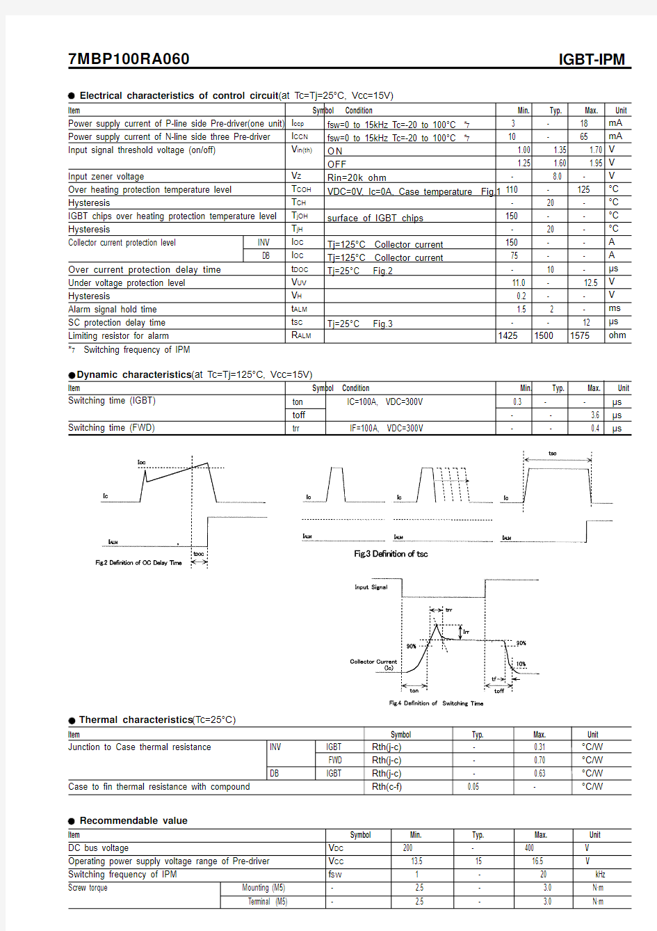
=600V input terminal open =600V input terminal open – – 1.0 mA – – 2.8 V – – 3.0 V – – 1.0 mA – – 2.8 V – – 3.3 V Fig.1 Measurement of case temperature
7MBP100RA060IGBT-IPM
Thermal characteristics(Tc=25°C)
Item Symbol Typ. Max. Unit
Junction to Case thermal resistance
Case to fin thermal resistance with compound
Rth(j-c)
Rth(j-c)
Rth(j-c)
Rth(c-f)
- 0.31
- 0.70
- 0.63
0.05 -
°C/W
°C/W
°C/W
°C/W INV IGBT
FWD
DB IGBT
Item Symbol Min. Typ. Max. Unit
DC bus voltage
Operating power supply voltage range of Pre-driver Switching frequency of IPM
Screw torque Mounting (M5) Terminal (M5)V DC 200 - 400 V
V CC 13.5 15 16.5 V
f SW 1 - 20 kHz - 2.5 - 3.0 N·m - 2.5 - 3.0 N·m
Recommendable value
Block diagram
Pre-drivers include following functions
a) Short circuit protection circuit
b) Amplifier for driver
c) Undervoltage protection circuit
d) Over current protection circuit
e) IGBT chip over heating protection 7MBP100RA060
IGBT-IPM
Outline drawings, mm
Mass : 440g
7MBP100RA060IGBT-IPM
Characteristics (Representative)
Control Circuit
7MBP100RA060IGBT-IPM Inverter
7MBP100RA060IGBT-IPM
7MBP100RA060IGBT-IPM
7MBP100RA060IGBT-IPM Brake