Sensor Bus_An Intermediary Layer for Linking Geosensors and the Sensor Web
- 格式:pdf
- 大小:308.07 KB
- 文档页数:8

地理相关英语词汇--------------------------------------------------------- abandoned land 弃耕地abiltic factor 非生物因素;非生命因素abiotic environment 非生物环境;非生命环境ablation 消融〔作用〕Abney level 手水准仪aborigine 土著abrasion (corrasion) 磨蚀〔作用〕刻蚀〔作用〕abrasion (wave-cut) platform 海蚀平台absolute humidity 绝对湿度absolute instability 绝对不稳定〔状态〕absolute stability 绝对稳定〔状态〕absolute temperature 绝对温度absorption 吸收〔作用〕abyssal region 深海区acacia 合欢树Acacia confusa 台湾相思accelerated erosion 加速侵蚀accessibility 可达度;能达度acclimatization 气候适应accordant drainage 协调水系;调和水系accretion 加积〔作用〕accumulated temperature 积温acid lava 酸性熔岩acid rain 酸雨acid soil 酸性土壤acidic rock 酸性岩acidity (1) 酸度,(2) 酸性activated sludge 活性污泥active layer 活动层;活土层active recreation 主动性康乐active volcano 活火山activity space 活动空间actual evapotranspiration 实际蒸散〔量〕adiabatic cooling 绝对冷却;绝热降温adiabatic heating 绝对增温adiabatic lapse rate 绝热递减率;绝热直减率adiabatic process 绝热过程adiabatic temperature change 绝热温度变化adit mining 棋坑开采法advection 平流advection fog 平流雾aeolian deposit (sediment) 风积物aeration (1)通气[性],(2)曝气aeration tank 曝气池aerial photograph 航空照片;空中照片aerobic 需氧aerobic treatment 需氧处理aerosol 气溶胶;雾体;大气微粒aesthetic pollution 美感污染aesthetic quality 美感质素afforestation 造林;植林aftershock 余震age composition 年龄构成age group 年龄组别age structure 年龄结构aged-dependency ratio 老年人抚养〔比〕率agents of erosion 侵蚀作用力;侵蚀营力age-sex pyramid 年龄性别金字塔age-specific fertility rate 年龄别生育率age-specific marriage rate 年龄别结婚率age-specific mortality rate 年龄别死亡率agglomerate 集块岩agglomerated settlement 集居聚落agglomeration (1)结集;聚结,(2)聚居点agglomeration economies 集聚经济效益aggradated plain (aggradation plain) 加积平原;填积平原aggradation 右积作用;填积作用aggradation plain (aggradated plain) 加积平原;填积平原aggregate 团聚体;集合体aging of population 人口老化agrarian reform 土地改革agricultural location theory 农业区位理论agricultural waste 农业废料agriculture 农业agro-ecosystem 农业生态系统agrosystem 农业系统A-horizon A层;淋溶层air circulation 空气环流;空气循环air composition 空气成分;空气组成air control zone 空气管制区air mass 气团air mass modification 气团变性air parcel 气块air pollutant 空气污染物air pollution 空气污染;大气污染air pollution source 空气污染〔来〕源air pressure 气压air quality monitoring network 空气质素监察网albedo 反射率alfalfa 苜蓿alfisol 淋溶土algae 藻类algal bloom 藻类过量繁殖alkaline soil 碱性土alkalinity (1)碱度,(2)碱性alkalization 碱化〔作用〕allogenic river 外源河alluvial cone 冲积锥alluvial deposit 冲积物alluvial fan 冲积扇alluvial plain 冲积平原alluvial soil 冲积土alluvial terrace 冲积阶地alluviation 冲积作用alluvium 冲积物;冲积层alpine 高山alpine meadow soil 高山草甸土Alpine mountain-building movement 阿尔卑斯造山运动alpine vegetation 高山植物Alpine-Himalayan Belt 阿尔卑斯--喜马拉雅山带altimeter 高度计altiplano 高原(玻利维亚)altitude 高度altocumulus 高积云altostratus 高层云aluminium sesquioxide 三氧化二铝amenities 市容ammonia 氨ammophilous 喜砂amorphous 无定形amplitude (1)幅度,(2)振幅anabatic wind 上坡风anaerobic 厌氧anaerobic treatment 厌氧处理;缺氧处理ancillary service 辅助性服务〔行业〕anemometer 风速计aneroid barometer 空盒气压计angle of depression 俯角angle of elevation 仰角angle of incidence 入射角angle of inclination 倾角angle of repose 休止角angular (compass, whole circle) bearing 方位角angulate drainage 角状水系animal husbandry 畜牧〔业〕anion 阴离子;负离子annotated map 注释图annual flood 年最大流量;年最大洪水annual mean temperature 年平均温annual rainfall 年雨量annual range of temperature 年温差annual runoff 年径流;年径流量annular drainage 环状水系Antarctic Circle 南极圈antecedent drainage 先成水系anthracite 无烟煤anthropogenic factor 人为因素anticline 背斜anticyclone 反气旋anticyclonic circulation 反气旋式环流anvil cloud 砧状云apartment building 住宅大厦apex (1)冲积扇顶,(2)顶点aquaculture 水产养殖aquatic plant 水生植物aqueduct 引水槽aquifer 畜水层arable farming 耕作农业arable land 〔可〕耕地arch (1)背斜,(2)拱顶,(3)穹窿Archimedes' screw 〔阿基米得式〕螺旋水斗archipelago 群岛Arctic air mass 北极气团Arctic Circle 北极圈Arctic climate 北极气候arctic front 北极锋arcuate delta 弓形三角洲;扇形三角洲area sampling 区域抽样;地区抽样areal association 地区联系;地域联系areal differentiation 地域分异areal distribution 地区分布;地域分布areal specialization 地区专门化;地域专门化areal variation 地区差异;地域差异arete 刃脊;冰脊arid 干旱arid {dry} climate 干旱气候arid land 旱地aridisol 旱成土aridity 干燥〔度〕干旱〔度〕arithmetic mean 算术平均;等差中项;算术中项arithmetic progression 等差级数;算术级数arterial highway 干线公路artesian basin 自流水盆地artesian water 自流水artesian well 自流井artificial climate 人造气候asbestosis 石棉沉着病ash and cinder cone 凝灰火山渣锥ash cone 凝灰火山锥ash lagoon 煤灰湖asker 蛇〔形〕丘aspect 坡向assembly industry 装配工业assembly line 装配线assimilation 同化〔作用〕association 联系assumed mean 假定平均数asthenosphere 软流圈;岩流圈asymmetrical fold 不对称折曲atlas 地图集atmosphere 大气;大气圈atmospheric absorption 大气吸收atmospheric circulation 大气环流atmospheric disturbance 大气扰动atmospheric heat balance 大气热平衡atmospheric heat source 大气热源atmospheric motion 大气流动atmospheric pollutant 大气污染物atmospheric pollution 大气污染atmospheric pressure 大气压力;气压atmospheric radiation 大气辐射atmospheric refraction 大气折射atoll 环礁attrition 磨耗〔作用〕自磨〔作用〕aureole 〔接触〕变质带autotroph 自养生物autotrophic nutrition 自养营养autumnal equinox 秋分available relief (relative relief) 有效地势;相对地势avalanche 雪崩;山崩average cost 平均成本axial growth 轴向增长axial plane 轴面axial stream 山谷主要河流azimuth 方位角azonal soil 泛域土baby boom 生育高峰back bearing 倒后方位backshore 后滩;滨后〔滩〕backwall 后壁;后坡backwash 回流badland 劣地bajada (bahada) 山麓冲积扇带balanced community 均衡社区balanced ecosystem 平衡生态系统Baltic-Danish farming 波罗的--丹麦农业bank deposit 河岸沉积〔物〕bank erosion 河岸侵蚀bank failure 塌岸bank full stage 满岸水位bank protection 护岸bankfull discharge 满岸流量bar 沙洲;沙坝bar chart (graph) 条形图;棒形图barbed drainage 倒状水系barchan 新月形沙丘barogram 自记气压曲线图barograph 自记气压计barometer 气压计barometric gradient 气压梯度barren land 荒地;瘠地barrier reef 堡礁;堤礁barrier to migration 迁徙障碍barysphere 重圈basal sapping 基部掏蚀basalt 玄武岩base flow 基本径流;底流base level 基准面base map 底图;基本图basic industry 基础工业basic lava 基性熔岩basic rock 基性岩basic sector 基础部门basin 盆地basin irrigation 淹灌basin perimeter 流域周长;流域周界basin planning 流域规划basin-and-range terrain 盆山相间地形batholith 岩基bauxite 铝土矿bayhead beach 湾头滩bazaar-type economy 摊贩经济beach 海滩beaded stream 串珠〔状〕河流Beaufort scale 蒲福风级bed load 推移质;底沙bed scour 河床冲刷bedding 层理bedding plane 层面bed-load discharge 推移质输送量;底沙输送量bed-load transport 推移质输送;推移质搬运bedrock 基岩;底岩beef cattle 肉用牛behavioral adjustment 行为适应beheaded river (stream) 断头河bell-shaped curve 钟形曲线belt transect 样带bench 阶地bench mark (BM) 水准点beneficiation 矿物增效处理;富集bergschrund 冰后隙;冰斗隙best fit line 最优拟合线B-horizon B层;淀积层bias 偏误;偏差bidder 投标人;出价人bid-rent 出价地租bid-rent curve 出价地租曲线bifurcation ratio 分叉比;分叉率bimodal 集峰binomial curve 二项曲线biochemical oxygen demand(BOD) 生化需氧量biocycle 生物循环biodegradation 生物降解biogeochemical cycle 生物地球化学循环biogeography 生物地理学biological concentration 生物密集biological control 生物防治biological indicator 指示生物biological monitor 生物调节者biological productivity 生物生产力biological purification 生物净化biological weathering 生物风化biomass 生物量biome 生物群落biosphere 生物圈biota (biotic community) 生物群biotic balance (equilibrium) 生物平衡biotic barrier 生物阻限biotic climax 生物顶极〔群落〕biotic community (biota) 生物群biotic component 生物组元biotic condition 生物条件biotic environment 生物环境;生命环境biotic equilibrium (balance) 生物平衡biotic factor 生物因素;生命因素biotite 黑云母biotype 生物〔类〕型bird's foot delta 鸟足状三角洲birth control 节育;计划生育birth rate 出生率birth-death ratio 生死比率bituminous coal 烟煤black alkali soil 黑碱土black earth 黑土blast furnace 鼓风炉bleached horizon 漂白层blighted area (1)萎缩地区,(2)枯萎区blizzard 暴风雪;雪暴block diagram 立体图block disintegration 块状崩解;块状分裂block mountain 断块山blood rain 血雨blood worm 红虫;颤虫blow-hole 吹穴blowout (deflation hollow) 吹蚀穴;风蚀洼地bluff 陡坡;陡崖body wave 体波bog 藓沼;沼泽bog peat 沼泽泥炭bora 布拉风(地中海北岸)boreal climate 北部〔森林〕气候boreal forest 北部针叶林borehole 钻孔;探孔boulder 巨砾;石砾boulder clay 泥砾boulder fan 巨砾扇boulder-controlled slope 砾块控制坡boundary (1)界限,(2)边界boundary layer 边界层brackish water 微咸水brackish water habitat 微咸水生境braided stream 分汊河道branching channel 辫状河breaching of dyke 决堤break8ing point 市场分界点breaker zone 碎波区;破波区break-of-bulk-point 转运点breakwater 防波堤breccia 角砾岩breeder reactor 增殖反应堆breeze 微风bridging point 架桥点broad-leaved forest 阔叶林bromine 溴bronchial ailment 支气管失调brown desert steppe soil 棕色荒漠草原土;棕钙土brown earth 棕壤brown forest soil 棕色森林土brown podzolic soil 灰化棕色土;灰化棕壤browsing stock 放牧牲畜buckling (1)弯曲,(2)地壳弯曲buffer 缓冲built-up area 已建区bulk carrier 散装货轮bund 堤Burgess's Concentric Model 伯吉斯同心区模式burrowing animal 穴居动物;钻洞动bush fallowing 灌丛休耕法bush veld 灌丛草原(南非)bushfire 林火business turnover 营业额butte 小方丘;孤丘buttress root 板根by-census 中期人口普查;中期户口统计cactus 仙人掌cadmium 镉Cainozoic (Cenozoic) era 新生calcareous crust 代钙质地表层;石灰结皮;石灰结壳calcareous rock 钙质岩calcareous soil 钙质土;石灰性土壤calcic horizon 钙质层calcification 钙化作用calcimorphic soil 钙成土calciphilous plant 适钙植物;喜钙植物calcite 方解石calcium carbonate 碳酸钙caldera 破火山口Caledonian mountain-building movement 加里东造山运动caliche 钙质层calm (1)无风,(2)静calorie 卡路里;卡Cambrian period 寒武纪camouflage 保护色作用canopy 冠层canyon 峡谷cape 岬〔角〕capillary action 毛〔细〕管作用capital (1)资金;资本,(2)首都capital accumulation 资本累积capital city 首都capital goods 资本货物capital investment 资本投资capital-intensive industry 资本密集工业cap-rock 冠岩;覆盖石caravan 商队(北非)carbohydrate 碳水化合物carbon cycle 碳循环carbon monoxide 一氧化碳carbonaceous rock 炭质岩carbonation 碳化作用carbonic acid 碳酸Carboniferous period 石炭纪carcinogen 致癌物cardinal points 方位基点caribou 驯鹿carnivore 食肉动物;食肉生物carrying capacity 负载能力cartographic technique 绘图技巧cartography 绘图学cascade 小瀑布case study 个案研究;学习事例cash crop 经济作物;现金作物cash tenancy 现金租用耕地制cassava 木薯cast iron 铸铁cataract 急流catastrophic effect 灾难性后果catch crop 填闲作物catchment area (1)集水区,(2)从属区catchwater 引水道category 类型;类别catena (soil catena) 土链cation 阳离子;正离子cation exchange capacity 阳离子交换能力;正离子交换能力cattle rearing 牧牛业cavern 岩洞cavitation 空化〔作用〕cellular circulation 环型环流Celsius scale 摄氏温度表cementation 胶结〔作用〕Cenozoic (Cainozoic) era 新生代census 代人口普查;户口统计central business district (CBD) 商业中心区central city 中心城central place 中地;中心地central tendency 集中趋势centrality 中心性centralization 集中centrally-planned economy 中央计划经济centre of gravity 重心centrifugal drainage 离心水系centrifugal force 离心力centripetal drainage 向心水系centripetal force 向心力cereal 谷类cesspool 污水池;粪池chain island 列岛chain shop 连锁店chalk 白垩chance factor 机遇因素channel (1)海峡,(2)水道,(3)河槽;河床channel capacity 河道容量channel cutting 河道割切channel density 河网密度channel equilibrium 河道平衡channel erosion 河道侵蚀channel filling 河道淤塞channel flow 河道径流;河槽径流channel frequency 河道频数channel gradient (slope) 河道坡度;河床坡度channel improvement 河道整治channel length 河道长度channel realignment 河道改道channel roughness 河床糙度channel slope (gradient) 河道坡度;河床坡度channel width 河道宽度channelled runoff 河道径流channelling 开渠;开新槽chaparral 浓密常绿阔叶灌丛(美国加利福尼亚和墨西哥) chart 图;图表chemical industry 化学工业chemical oxygen demand (COD) 化学需氧量chemical waste 化学废物chemical weathering 化学风化chemically formed sedimentary rock 化学作用形成的沉积岩chemosynthesis 化合作用;化学合成chernozem 黑钙土chestnut brown soil 栗钙褐土chestnut soil 栗钙土child-bearing age group 生育年龄组chili 奇利风(突尼斯的干热风)chinook 钦诺克风(北美)chi-square 卡方chloroflurocarbons (CFCs) 氯氟碳chlorophyll 叶绿素C-horizon C层;母质层choropleth map 等值域图Christaller's Central Place Theory 克里斯泰勒中地学说chute (1)奔流;瀑流,(2)流槽cinder cone 火山渣锥circular causation 循环因果circum-Pacific belt 环太平洋带circumpolar westerlies 环极西风cirque (corrie, cwm) 冰斗cirrocumulus 卷积云cirrostratus 卷层云cirrus 卷云city 城市city (urban) planner 城市规划师city (urban) planning 城市规划city centre 市中心city plan 城市平面图city proper 城市市区部分class 区;组;类class boundary 组界class interval 组区间;组距class limit 组限;区限class mark (class mid-point) 组中点;组中点class mid-point (class mark) 组中点;区中点clastic deposit 碎屑沉积clay 黏土clay loam 黏质壤土clay pan 黏盘clay particle 黏土颗粒clayey 黏质clay-humus complex 黏粒腐殖质复合体cliff 悬崖;峭壁climate 气候climate modification 〔人工〕改变气候climatic amelioration 气候改良climatic anomaly 气候异常climatic barrier 气候障壁climatic change 气候变化;气候变迁climatic classification 气候分类climatic climax 气候顶极〔群落〕climatic deterioration 气候恶化climatic element 气候要素climatic factor 气候因子climatic graph 气候图〔表〕climatic map 气候图climatic oscillation 气候变化;气候变动climatic prediction 气候预报climatic region 气候区climatic regulation 气候调节〔作用〕climatology 气候学climax 顶极〔群落〕climax community 顶极群落climax vegetation 顶极植物climber 攀绿植物climbing plant 攀绿植物climograph 气候图clinometer 倾角仪;测斜仪clint 石灰岩岩脊;石芽closed system 密闭系统clothing industry 制衣业cloud 云cloud cover (cloudiness) 云量cloud reflection 云盖反射cloud seeding 播云;云的催化cloud type 云型cloudiness (cloud cover) 云量cluster sampling 类集抽样coagulation 混凝coal seam 煤层coalfield 煤田coarse texture soil 粗质地土壤coarse tuff 粗粒凝灰岩coarse-grained rock 粗粒岩石coastal landform 海岸地貌;海岸地形coastal plain 海岸平原coastline 海岸线cobble 中砾coding 编码cohesion 内聚力;凝聚力cohort 同期组群coking coal 〔炼〕焦煤col 山口;山坳cold current 寒流cold desert 寒〔带荒〕漠cold front 冷锋cold resistance 耐寒性cold temperate climate 寒温带气候cold wave 寒潮collective farming 集体农业collectivization 集体化colloid 胶体colluvium 崩积物;崩积层;坡积物colonization (1)殖民;拓殖,(2)集群;定殖;占据colony 集群;群体columnar jointing 柱状节理columnar structure 柱状结构combine harvester 联合收割机;多用途收割机commercial centre 商业中心commercial farming 商业性农业commercial zone 商业区commercialization 商业化commune 公社communication (1)交通,(2)通讯community (1)社区,(2)群落community facility 社区设施community organization 社区组织community shopping centre 社区购物中心commuter 通勤者;往返市区工作地点及郊区住所的人commuter zone 通勤带compact texture 致密结构comparative advantage 相对优势comparison goods 需比较商品compass 罗盘;指南针compass (angular, whole circle) bearing 方位角compass points 罗盘指标;罗盘方位competence of stream 河流搬运最大颗粒能力competition for location 区位竞争competition for space 空间竞争component 组元composite cone 复合火山锥composting 堆肥comprehensive redevelopment area 综合性重建区compressional force 挤压力computation 计算concave bank 凹岸concave slope 凹坡concentration 集结concentric zone theory 同心圆地带论concordant (longitudinal) coast 顺向海岸;纵式海岸concretion 结核〔作用〕condensation 凝结condensation level 凝结高度condensation nuclei 凝结核心conduction of heat 热传导conelet 小型火山锥confluence 汇流点congelifraction 融冻〔崩解〕作用conglomerate 砾岩conical hill 锥形山conifer 针叶树coniferous forest 针叶林connectivity 连接程度consequent drainage 顺向水系conservation 养护;保养;保护;保存;节约conservation of resources 资源保养constant slope 直坡constructive plate boundary 建设性皮块边界constructive wave 建设性波浪;堆积浪consumer 消费者consumer behaviour 消费行为;消费者行为container 集装箱;货柜container terminal 集装箱码头;货柜码头containerization 集装箱化;货柜化continent 洲;大陆continental air mass 大陆气团continental apron (rise) 大陆隆continental climate 大陆〔性〕气候continental collision 大陆碰撞continental crust 大陆地壳;陆壳continental drift 大陆漂移continental edge (fringe, margin) 大陆边缘continental fringe (edge, margin) 大陆边缘continental glacier 大陆冰川continental island 大陆岛continental margin (edge, fringe) 大陆边缘continental nucleus 陆核continental plate 大陆板块continental plate boundary 大陆板块边界continental rise (apron) 大陆隆continental rupture 大陆破裂continental shelf 大陆〔棚〕架continental shield 地盾continental slope 〔大〕陆〔斜〕坡continental suturing 大陆缝合作用continentality 大陆性;大陆度contour farming (ploughing) 等高耕作〔法〕contour line 等高线contour map 等高线图contour mapping 等高线绘图contour method 等高线法contour ploughing (farming) 等高耕作〔法〕contraception 避孕contract farming 合约式农业controlled flooding 控制漫灌〔法〕controlled tip 废物堆填区controlled tipping 废物堆填法conurbation 联都;集合城市〔区〕convection (convectional) rain 对流雨convection (convective) current (1)对流,(2)对流气流convection of heat 热对流convective (convection) current (1)对流,(2)对流气流convenience goods 日用品;常用商品conventional sign 图例;沿用图例;惯用符号convergence (1)辐合,(2)聚合convex bank 凸岸convex slope 凸坡cool temperate climate 凉温带气候co-operative farming 合作社式农业coordinate 坐标coral reef 珊瑚礁cordillera 雁列山(美洲 )core (1) 地核;地心,(2)核心core area 核心区corestone 核心石;岩心Coriolis effect 科里奥效应Coriolis force 科里奥利力;地球自转偏向力Corn Belt 玉米带(美)corrasion (abrasion) 磨蚀〔作用〕刻蚀〔作用〕corrective measure 改善措施correlation 相关corrie (cirque, cwm) 冰斗corrosion 溶蚀〔作用〕cosmic ray 宇宙射线cost minimization 生产成本最低化;成本的极少化cost of living 生活费cost-benefit analysis 损益分析;成本收益分析cottage industry 家庭式工业counter radiation 逆辐射counter-urbanization 逆城市化country park 郊野公园country rock 围岩crag and tail 鼻尾丘crater 火山口crest 山脊Cretaceous period 白垩纪crevasse 冰隙;裂隙critical discharge 临界流量critical isodapane 临界等总运费线crop and livestock farming 耕牧混合农业crop breeding 作物育种crop failure 作物失收;作物减产crop rotation 轮植;轮作;轮耕cropping pattern 作物生产型式cropping region 作物区cropping system 耕作制度;农作制度cross breeding 杂交育种;杂交繁育cross section 横剖面;横切面cross-bedding 交错层crown 树冠crude birth rate 粗出生率;毛出生率crude death rate 粗死亡率;毛死亡率crumb structure 屑粒结构crust (earth's crust) 地壳crystal 晶体crystalline rock 结晶岩crystallization 结晶〔作用〕cuesta 单斜脊;单面山cuesta scarp 单斜脊崖(前坡);鬣崖cultural landscape 文化景观cumulative causation 累积因果cumulative frequency 累积频数;累积频率cumulative frequency curve 累积频数曲线;穹形线cumulonimbus 积雨云cumulus 积云cup anemometer 转杯风速计curde oil 原油current meter 流速计current speed 流速cuspate delta 尖头三角洲cut off slope 削蚀坡cut-and-fill (1)边冲边淤(曲流) (2)先冲后淤(河床) cuticle 角质层cut-off (1)截流;断流,(2)裁湾〔作用〕cut-off lake (oxbow lake) 牛轭湖cutting 〔削〕切面cwm (cirque, corrie) 冰斗cycle of erosion 侵蚀循环cycle of poverty 贫穷循环cyclone 气旋cyclone track 气旋路线cyclonic circulation 气旋环流cyclonic flow 气旋流动cyclonic rain 气旋雨daily (diurnal) range of temperature 日温差dairy cattle 乳牛;乳用牛dairy farming 乳牛畜牧业Dalmatian coast 达尔马提亚型海岸;顺向海岸dam 水坝dam-failure 溃坝;垮坝data analysis 数据分析;资料分析data collection 数据搜集;资料搜集data interpretation 数据阐释;资料阐释data processing 数据处理;数据处理data representation 数据表达;资料表达de facto population 现住人口de jure population 常住人口death rate 死亡率debris avalanche 岩屑崩落debris flow 泥石流debris slope 岩屑坡decalcification 脱钙作用decay 腐烂;分解decentralization 分散;离心decibel (dB) 分贝deciduous forest 落叶林decision maker 决策者declining region 衰落区decomposer 分解者decomposing organism 分解生物decomposition 分解〔作用〕deep-focus earthquake 深源地震deferred junction 延长汇点deferred stream 延长河deflation 吹蚀〔作用〕deflation hollow (blowout) 吹蚀穴;风蚀洼地deflation varnish 吹蚀漆皮deflection 偏向deflection (deflective, deviating) force 偏向力;偏转力deflective (deflecting, deviating) force 偏向力;偏转力defoliation 去叶;落叶;脱叶deforestation 伐林deformation 变形;变态deglomeration 反聚集力degradable plastics 可降解塑料degradation 陵削〔作用〕减坡degrading stream 夷低河;削蚀河;下切河流dehydration 脱水〔作用〕deionized water 去离子水delta 三角洲demand potential 需求潜在力demographic data 人口数据;人口资料demographic structure 人口结构demographic transition 人口过渡;人口转变demographic transition theory 人口过渡论demography 人口统计学;人口学dendritic drainage 〔树〕枝状水系denitrification 反硝化作用densely populated 人口稠密density 密度density map 密度图denudation 剥蚀〔作用〕denudation chronology 剥蚀年代dependency population 依赖人口;受抚养人口dependency ratio 依赖比率;抚养比率dependent variable 应变量;应变数depopulation 人口减少;人口下降deposit 沉积物deposition 沉积〔作用〕depreciation (1)折旧,(2)贬值;货币贬值depressed region 葨落区域depression (1)低气压,(2)洼地deranged drainage 冰碛平原水系;扰乱水系desalinization 脱盐作用descriptive statistics 描述统计学desert 荒漠;沙漠desert climate 荒漠气候;沙漠气候desert encroachment 荒漠扩展;沙漠扩侵desert pavement 荒漠〔卵石〕覆盖层;沙漠〔卵石〕覆盖层desert plateau 荒漠高原;沙漠高原desert varnish 荒漠漆皮desertification 荒漠化;沙漠化desiccation 干燥作用;变旱desilication 脱硅作用destructive plate boundary 破坏性板块边界destructive wave 破坏性〔波〕浪detached building 独立式楼宇detritus (1)碎屑;岩屑,(2)腐屑developed country 已发展国家developing country 发展中国家development level 发展水平deviating (deflecting, deflective) force 偏向力;偏转力deviation 偏差Devonian period 泥盆纪dew 露dew point 露点D-horizon D层;基岩层diagenesis 成岩作用diagonal linkage 对角联系diastrophism 地壳运动differential erosion 差别侵蚀differential weathering 差别风化diffuse radiation 扩散辐射diffusion 漫射;扩散dike (dyke) (1)岩墙;岩脉,(2)堤dilution 稀释diminishing return 收益递减dip 倾斜dip angle 倾角dip direction 倾向dip slope 倾向坡direct proportion 正比例disaster relief 救灾discharge 流量disclimax 亚演替顶极discordant coast 横或海岸discordant drainage 不协调水系discrete data 不连续数据disease control 疾病控制diseconomies of scale 规模不经济disintegration 崩解;分解dismembered drainage 解体水系dispersed settlement 分散聚落dispersion (1)离〔中〕趋势;离〔中〕差,(2)离散displacement 位移disposal 处置;处理dissected plateau 切割高原dissection 切割〔作用〕分割〔作用〕dissipation 消散〔作用〕dissolved load 溶解〔搬运〕质dissolved oxygen (DO) 溶解氧distance decay 随距递减;随距衰减distributary 分流distribution 分布distributional pattern 分布形态diurnal (daily) range of temperature 日温差divergence (1)辐散,(2)分向diversification 多元化divided circle (pie graph) 圆瓣图division of labour 分工doldrums 赤道无风带dolerite 粗玄岩doline 溶斗;〔漏斗形〕灰岩坑domain 领域dome 穹丘,圆丘domesti refuse 家庭废物domestic sewage 生活污水;家庭污水domesticated animal 驯养家畜domestication 驯化;驯养dominant animal 优势动物dominant plant 优势植物dominant species 优势种dormancy 休眠dormant volcano 睡火山dormitory suburb 郊外居住区;郊外住宅区dormitory town 居住城镇dot map 点示图double cropping 雨造耕作;双作downcutting 下蚀〔作用〕下切侵蚀downdraft (downdraught) 下沉气流downfold 向斜downstream 下游downthrow 下盘downtown 市中心;城市商业区(美)downward filtering process 下滤过程downwelling 沉降流downwind effect 下沉风效应drag velocity 摩阻流速drainage (1)水系,(2)排水drainage area (1)流域,(2)排水区drainage basin 河盆;河域drainage density 河网密度;排水密度drainage network (1)河网,(2)排水网drainage pattern 水系型〔式〕drainage system 水系draught animal 役畜dredging 清淤;疏浚dreikanter 三棱石;风棱石drift (adlt) mining 横坑开采法drift material 飘流物;漂流物drill rig 钻油台;钻塔drip-tip 滴水叶尖drizzle 微雨;毛毛雨drought 干旱drought-resistant plant 抗旱性植物drowned river valley (rai) 溺谷;溺河drumlin 脊背丘;鼓丘dry (arid) climate 干旱气候dry (wind) gap 旱峡;风口dry adiabatic lapse rate 干绝热〔温度〕递减率;干绝热〔温度〕直减率dry crop 旱田作物dry farming 旱耕〔法〕dry rice 旱稻dry valley 干谷;涸谷dry-bulb thermometer 干球温度计drying agent 干燥剂duckweed 浮萍;青萍dumping area 倾卸区dune 沙丘dune encroachment 沙丘扩侵duplex house 复式房屋durable goods 耐用品duricrust 铝铁硅钙壳duripan 硬盘Dust Bowl 尘暴区(美)dust storm 尘暴dwelling unit 居住单位dyke rock 脉岩dyke(dike) (1)岩墙;岩脉,(2)堤dynamic equilibrium 动态平衡earth movement 地壳运动earth pillar 土柱earth revolution 地球公转earth rotation 地球自转earth-flow 泥流earthquake 地震earthquake focus 震源earthquake intensity 地震强度earthquake origin 震源earthquake period 地震期earthquake prediction 地震预报earthquake scale 地震震级earthquake wave 地震波earthquake zone 地震带earthquake-prooff design 抗震设计earth's axis 地轴earth's crust (crust) 地壳earthy 土状easterlies (1)东风,(2)东风带easting 东行线ecocline 生态变异;生态差型ecological balance 生态平衡ecological community 生态群落ecological crisis 生态危机ecological damage 生态破坏ecological efficiency 生态效率ecological niche 生态位;小生境ecological pyramid 生态塔ecological succession 生态演替ecology 生态学economic base 经济基础economic bloc 经济集团economic depression 经济萧条economic development 经济发展economic growth 经济增长economic man 经济人economic recession 经济衰退economic recovery 经济复苏economic region 经济区economic rent 经济租值economic take-off 经济起飞economic utility 经济效用economically active population 经济活动人口economically inactive population 非经济活动人口economies of scale 规模经济效益ecosphere 生态圈ecosystem 生态系统ecotone 群落过渡带;群落交错区ecotype 生态型edaphic climax 土壤演替顶极〔群落〕edaphic factor 土壤因素eddy 旋涡effciency of energy transfer 能量变换效率;能量转换效率effective precipitation 有效降水〔量〕effluent (1)污水;废水,(2)湖源河eight point compass 八方位罗盘elasticity of demand 需求弹性elasticity of supply 供给弹性elbow of capture 袭夺〔河〕弯electrical conductivity 导电性;导电率electromagnetic wave 电磁波electronics industry 电子业elevated peneplain 上升准平原elevation (1)海拔;高度,(2)仰角eluvial deposit (1)残积物,(2)淋溶沉积物eluvial horizon 淋溶层eluviation 淋溶〔作用〕淋失〔作用〕embankment 堤基emergence 上升emergent (1)露生植物,(2)挺水植物emergent coast 上升海岸emigrant 移民emigration 移居国外empirical data 实验数据employment structure 就业结构end (terminal) moraine 终〔冰〕endangered species 濒临灭绝的生物品种;濒危物种endogenic process 内力作用;内成作用energy balance 能量平衡energy budget 能量收支energy conservation 能源节约energy crisis 能源危机energy deficit 能量亏损energy efficiency 能量效率;能源效率energy flow 能〔量〕流energy level 能量级energy ratio 能量比率energy reserve 能源蕴藏energy resources 能源〔资源〕energy source 能源energy subsidy 能源补助energy surplus 能量过剩energy transfer 能量转移engineering industry 机械工业englacial moraine 内〔冰〕碛entisol 新成土entrenched meander 嵌入曲流;深切曲流entrenched stream 嵌入河;深切河entrenched valley 嵌入〔河〕谷;深切〔河〕谷entrepot 转口港entrepreneur 企业家entrepreneurial factor 企业管理因素environmental capacity 环境容量environmental conservation 环境保护environmental constraint 环境限制environmental degradation 环境退化environmental education 环境教育environmental gradient 环境梯度environmental hazard 环境灾害;环境危害environmental impact 环境影响environmental impact statment 环境影响报告environmental improvement 环境改善environmental lapse rate 环境〔温度〕递减率;环境〔温度〕直减率environmental perception 环境感观environmental planning 环境规则environmental pollution 环境污染environmental quality 环境质素environmental resources 环境资源environmental risk 环境风险Eocene epoch 始新世epeirogenic movement 造陆运动ephermeral (1)短生植物,(2)短生ephermeral stream 季节性河流;间歇〔性〕河〔流〕epicdermis 表皮epicentre 震央;震中epiphyte 附生植物Equator 赤道equatorial air mass 赤道气团equatorial climate 赤道气候equatorial low 赤道低〔气〕压equatorial rain forest 赤道雨林equatorial trough 赤道低压槽eradication of disease 消除疾病erg (sandy desert) 砂质荒漠;砂质沙漠erodibility 可侵蚀性erosion 侵蚀erosion cycle 侵蚀循环erratic 漂石eruption 爆发escarpment 单斜山;马头丘estancia 大牧场(南美)estate (1)大农场,(2)estuarine delta 河口三角洲estuary 河口湾ethnic area 种族区ethnic group 种族群ethnic minority 少数种族ethnic segregation 种族隔离Eurasia 欧亚大洲eustasy 海面升降;海面进退eustatic movement 海面升降运动eutrophic 富养分eutrophication 富养化〔作用〕evaporation 蒸发〔作用〕evapotranspiration 蒸发蒸腾作用even (regular) slope 均匀坡evergreen forest 常绿林evolution 演化;进化excavation (1)掘蚀,(2)挖掘excessive urbanization 过度城市化exchange capacity 交换量exchangeable cation 交换性阳离子;交换性正离子exfoliation 剥离〔作用〕;页状剥落〔作用〕exhaust gas 废气;排气exhumation 剥露〔作用〕exogenic process 外力作用;外成作用exotic river 外源河exponential curve 指数曲线export 出口export-oriented industry 出口导向工业exposed coast 裸露海岸;暴露海岸extended family 大家庭extensive farming 粗放式农业;广耕法external economies 外部经济效益external force 外〔营〕力external migration 国外迁移;境外迁移extinct species 已灭绝生物品种extinct volcano 死火山extinction of species 品种灭绝extrapolation 外推法;外插法extreme climate 极端气候extreme environment 极端环境extreme event 极端事件extreme value 极值extrusion 喷出;挤出extrusive rock 喷出岩extrusive vulcanicity 喷出火山作用eye of tropical cyclone 〔热带气旋〕风眼fabricating industry 装配工业factor of location 区位因素;布局因素factor of production 生产因素。
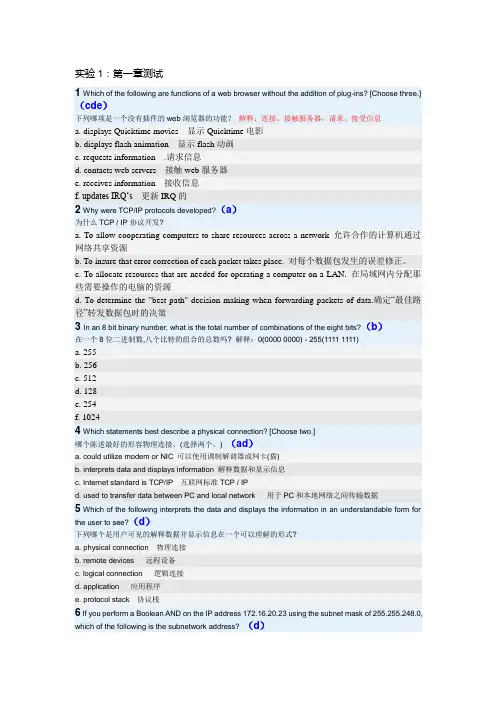
实验1:第一章测试1 Which of the following are functions of a web browser without the addition of plug-ins? [Choose three.](cde)下列哪项是一个没有插件的web浏览器的功能?解释:连接、接触服务器,请求、接受信息a. displays Quicktime movies 显示Quicktime电影b. displays flash animation 显示flash动画c. requests information .请求信息d. contacts web servers 接触web服务器e. receives information 接收信息f. updates IRQ…s更新IRQ的2 Why were TCP/IP protocols developed?(a)为什么TCP / IP协议开发?a. To allow cooperating computers to share resources across a network 允许合作的计算机通过网络共享资源b. To insure that error correction of each packet takes place. 对每个数据包发生的误差修正。
c. To allocate resources that are needed for operating a computer on a LAN. 在局域网内分配那些需要操作的电脑的资源d. To determine the "best path" decision making when forwarding packets of data.确定“最佳路径”转发数据包时的决策3 In an 8 bit binary number, what is the total number of combinations of the eight bits?(b)在一个8位二进制数,八个比特的组合的总数吗? 解释:0(0000 0000) - 255(1111 1111)a. 255b. 256c. 512d. 128e. 254f. 10244 Which statements best describe a physical connection? [Choose two.]哪个陈述最好的形容物理连接。

Making remote-sensing data accessible since 1991Sentinel-1 InSAR Processing using the Sentinel-1 Toolbox Adapted from coursework developed by Franz J Meyer, Ph.D., Alaska Satellite FacilityIn this document you will find:A. System requirementsB. Background InformationC. Materials ListD. Steps for InSAR ProcessingE. InSAR Extended Reading ListA) Some Advice on System RequirementsCreating an interferogram using Sentinel-1 Toolbox (S1TBX) is a very computer resource intensive process and some steps can take a very long time to complete. Here are some hints to help speed things up and keep the program from freezing.•Windows or Mac OS X•Requires at least 16 GB memory (RAM)•Close other applications•Do not use the computer while a product is being processed•Remove the previous product once a new product has been generatedB) Background1) IntroductionInterferometric SAR processing exploits the difference between the phase signals of repeated SAR acquisitions to analyze the shape and deformation of the Earth surface. The principles and concepts of Interferometric SAR (InSAR) processing are not covered in this tutorial, but may be found in the literature listed in Appendix A.The European Space Agency’s Sentinel-1A and Sentinel-1B C-band SAR sensors are delivering repeated SAR acquisitions with a predictable observation rate, providing an excellent basis for environmental analyses using InSAR techniques.In this data recipe, for demonstration purposes, we will analyze a pair of Sentinel-1 images that bracket the devastating 2016 Kumamoto earthquake, whose 6.5 magnitude foreshock and 7.0 main shock devastated large areas around Kumamoto, Japan in April 2016. Figure 1 shows the USGS ShakeMap associated with the 7.0 magnitude main shock, showing both the violence of the event and the location of the largest devastation.Figure 1: 2016 Kumamoto Earthquake, JP2) A Word on Sentinel-1 Interferometric Wide Swath (IW) DataThe Interferometric Wide (IW) swath mode is the main acquisition mode over land for Sentinel- 1. It acquires data with a 250km swath at 5m x 20m spatial resolution (single look). IW mode captures three sub-swaths using the Terrain Observation with Progressive Scans SAR (TOPSAR) acquisition principle.With the TOPSAR technique, in addition to steering the beam in range as in ScanSAR, the beam is also electronically steered from backward to forward in the azimuth direction for each burst, avoiding scalloping and resulting in homogeneous image quality throughout the swath. A schematic of the TOPSAR acquisition principle is shown below in Figure 2.The TOPSAR mode replaces the conventional ScanSAR mode, achieving the same coverage and resolution as ScanSAR, but with nearly uniform image quality (in terms of Signal-to- Noise Ratio and Distributed Target Ambiguity Ratio).IW Single Look Complex (SLC) products contain one image per sub-swath and one per polarization channel, for a total of three (single polarization) or six (dual polarization) images in an IW product.Figure 2: TOPSAR acquisition principleEach sub-swath image consists of a series of bursts, where each burst has been processed as a separate SLC image. The individually focused complex burst images are included, in azimuth-time order, into a single sub-swath image with black-fill demarcation in between, similar to ENVISAT ASAR Wide ScanSAR SLC products (see also Figure 5).3) Sentinel-1 and the Kumamoto EarthquakeThe sample images for this data recipe were acquired on April 8 and April 20, 2016, bracketing the fore and main shock of the Kumamoto earthquake event. Hence, the phase difference between these image acquisitions capture the cumulative co-seismic deformation caused by both of these seismic events. The footprint of the Sentinel-1 images (Figure 3) shows good correspondence with the areas affected by the earthquake (Figure 1).Figure 3: Footprint of the Sentinel-1A SAR data used in this data recipeC) Materials List1. Sentinel-1 Toolbox(S1TBX) Download2. Data (sample images provided)Pre event image sample:S1A_IW_SLC 1SSV_20160408T091355_20160408T091430_010728_01001F_83EB DownloadPost-event image sample:S1A_IW_SLC 1SSV_20160420T091355_20160420T091423_010903_010569_F9CE DownloadImportant: Do not unzip the downloaded files. If you are using Safari, in the top menunavigate to Safari > Preferences > General tab. Uncheck the box next to “Open safefiles after downloading” to prevent the files from automatically unzipping.Note: You will be prompted for your Earthdata Login username and password, ormust already be logged in to Earthdata before the download will begin.D) Steps for InSAR Processing∙Download software and data, and open data∙Open data in S1TBX∙Co-register the data∙Interferogram formation and coherenceo Form the interferogramo TOPS Debursto Topographic Phase Removalo Multi-looking & Phase Filteringo Geocoding & Export in a User-Defined Formato Combine subswaths – optionalDownload Software & Data, and Open Data1) Download materialsa. Download and install the S1TBX application (Select the correct version foryour operating system)b. Create a working folder for the Sentinel-1 sample images andintermediary products created during processingc. Download the sample images in Section C to the new working folder usingASF Vertex, or use the download links providedOpening Data in Sentinel-1 ToolboxStart the S1TBX application.Figure 4: Open Product dialog in Sentinel-1 Toolbox (S1TBX)In order to perform interferometric processing, the input products should be two or more SLC products over the same area acquired at different times, such as the sample images provided in this tutorial.1) Open the products –Step 1Use the Open Product button in the top toolbar and browse for the location of the Sentinel-1 Interferometric Wide (IW) SLC products (Figure 4).Important: Do not unzip the downloaded filesPress and hold the <Ctrl> button and select the files. Click <Open> to load the files into S1TBX.2) View the products –Step 2In the Product Explorer window (Figure 5) you will see the products.Double-click on each product to expand the view.Double-click Bands to expand the folder.In the Bands folder, you will find bands containing the real (i) and imaginary (q) parts of the complex data. The i and q bands are the bands that are actually in the product.The V(irtual) Intensity band is there to assist you in working with and visualizing the complex data.Figure 5: Product Explorer tab within the S1TBX user interfaceNote that in Sentinel-1 IW SLC products, you will find three subswaths labeled IW1, IW2, and IW3. Each subswath is for an adjacent acquisition by the TOPS mode.3) View a band –Step 3To view the data, double-click on the Intensity_IW1_VV band of one of the two images.Zoom in on the image and pan by using the tools in the Navigation window below the Product Explorer window. Within a subswath, TOPS data are acquired in bursts. Each burst is separated by a demarcation zone (Figure 6). Any ‘data’ within these demarcation zones can be considered invalid and should be zero-filled, but may also contain garbage values.Figure 6: Intensity image of IW1 swath with bursts and demarcationareas identifiedCo-register the DataFor interferometric processing, two or more images must be co-registered into a stack. One image is selected as the master and the other images are the ‘slaves’. The pixels in ‘slave’ images will be moved to align with the master image to sub-pixel accuracy. Coregistration ensures that each ground target contributes to the same (range, azimuth) pixel in both the master and the ‘slave’image. For TOPSAR InSAR, S-1 TOPS Coregistration is used.1) Co-register the images –Step 4Select S-1 TOPS Coregistration in the Radar menu.TOPS Coregistration consists of a series of steps:∙Reading the two data products∙Selecting a subswath with TOPSAR-Split∙Applying precision orbit correction with Apply-Orbit-File∙Conducting a DEM-assisted Back-Geocodingcoregistration All of these steps occur automatically onceprocessing starts.A window will open allowing you to set the parameters for the coregistration process(Figure 7).Figure 7: S1TBX co-registration interface∙In the Read tab, select the first product [1]. This will be your master image.∙In the Read(2) tab select the other product. This will be your ‘slave’image.∙In the TOPSAR-Split tabs, select the IW1 subswath for each of the products.∙In the Apply-Orbit-File tabs, select the Sentinel Precise Orbit State Vectors. Orbit auxiliary data contain information about the position of the satellite during the acquisition of SAR data. Orbit data are automatically downloaded by S1TBX and no manual search is required by the user.The Precise Orbit Determination (POD) service for Sentinel-1 provides Restituted orbit files and Precise Orbit Ephemerides (POE) orbit files. POE files cover approximately 28 hours and contain orbit state vectors at fixed time steps of 10-second intervals. Files are generated one file per day and are delivered within 20 days after data acquisition.If Precise orbits are not yet available for your product, you may select the Restituted orbits, which may not be as accurate as the Precise orbits but will be better than the predicted orbits available within the product.In the Back-Geocoding tab, select the Digital Elevation Model (DEM) to use and the interpolation methods. The default is the SRTM 3Sec DEM and this can be used for this tutorial. Areas that are not covered by the DEM or are located in the ocean may optionally be masked out. Select to output the Deramp and Demod phase if you require Enhanced Spectral Diversity to improve the coregistration.In the Write tab, set the Directory path to your working directory.Click <Run> to begin co-registering the data. The resulting coregistered stack product will appear in the Product Explorer window with the suffix Orb_Stack.Interferogram F ormation &C oherence E stimationThe interferogram is formed by cross-multiplying the master image with the complex conjugate of the ‘ slave’. The amplitude of both images is multiplied while their respective phases are differenced to form the interferogram.The phase difference map, i.e., interferometric phase at each SAR image pixel depends only on the difference in the travel paths from each of the two SARs to the considered resolution cell.1) Form the Interferogram –Step 5Select stack [3] in Product Explorer and selectInterferogram Formation from the Radar > Interferometric > Products menu.Through the interferometric processing flow we will try to eliminate other sourcesof error and be left with only the contributor of interest, which is typically thesurface deformation related to an event.The flat-earth phase removal is done automatically during the InterferogramFormation step (Figure 8). The flat-earth phase is the phase present in theinterferometric signal due to the curvature of the reference surface. The flat-earthphase is estimated using the orbital and metadata information and subtractedfrom the complex interferogram.Keep the default values for Interferogram Formation. Click <Run>.Visualize Interferometric PhaseOnce the interferogram product is created (product [4] in Product Explorer(appended with Orb_Stack_ifg), visualize the interferometric phase. You will stillsee the demarcation zones between bursts in this initial interferogram. This willbe removed once TOPS Deburst is applied.Figure 8: S1TBX Interferogram Formation InterfaceWhat it MeansInterferometric fringes represent a full 2π cycle of phase change. Fringes appear on an interferogram as cycles of colors, with each cycle representing relative range difference of half a sensor’s wavelength. Relative ground movement between two points can be calculated by counting the fringes and multiplying by half of the wavelength. The closer the fringes are together, the greater the strain on the ground.Flat terrain should produce a constant or only slowly varying fringes. Any deviation froma parallel fringe pattern can be interpreted as topographic variation.2) TOPS Deburst –Step 6To seamlessly join all bursts in a swath into a single image, we apply the TOPS Deburst operator from the Sentinel-1 TOPS menu.∙Navigate to the Radar > Sentinel-1 TOPS menu∙Select the S-1 TOPS Deburst step∙Keep the default values∙Click <Run>The resulting product will be appended with Orb_Stack_ifg_deb.3) Topographic Phase Removal –Step 7To emphasize phase signatures related to deformation, topographic phasecontributions are typically removed using a known DEM. In S1TBX, the Topographic Phase Removal operator will simulate an interferogram based on a reference DEM and subtract it from the processed interferogram.∙Navigate to the Radar > Interferometric > Products menu∙Select the Topographic Phase Removal stepS1TBX will automatically find and download the DEM segment required for correcting your interferogram of interest. Keep the default values and click <Run>. After topographic phase removal, the resulting product (appended with Orb_Stack_ifg_deb_dinsar) will appear largely devoid of topographic influence. Multi-looking & Phase FilteringYou will see that up to this stage, your interferogram looks very noisy and fringe patterns are difficult to discern. Hence, we will apply two subsequent processing steps to reduce noise and enhance the appearance of the deformation fringes.Interferometric phase can be corrupted by noise from:∙Temporal decorrelation∙Geometric decorrelation∙Volume scattering∙Processing errorTo be able to properly analyze the phase signatures in the interferogram, the signal-to-noise ratio will be increased by applying multi-looking and phase filtering techniques:4) Multi-looking –Step 8The first step to improve phase fidelity is called multi-looking. Navigate to the Radardropdown menu∙Select the Multilooking option (bottom of the menu). A new window opens.∙Click on the Processing Parameters tab∙Pick the i and q bands as the Source Bands to be multi-looked∙In the Number of Range Looks field, enter 6, which will result in a pixel size of about 25m (Figure 9)In essence, multi-looking performs a spatial average of a number of neighboringpixels (in our case 6x2 pixels) to suppress noise. This process comes at theexpense of spatial resolution.∙Click <Run>. The resulting product name is appended withOrb_Stack_ifg_deb_dinsar_ML.Figure 9: S1TBX Multilooking interface5) Phase Filtering - Step 9In addition to multi-looking, we perform a phase filtering step using a state-of-the art filtering approach.∙Navigate to Radar > Interferometric > Filtering∙Select Goldstein Phase Filtering∙Keep the default values and click <Run>The resulting product name is appended with Orb_Stack_ifg_deb_dinsar_ML_flt.After phase filtering, the interferometric phase is significantly improved, and the dense earthquake deformation-related fringe pattern is now clearly visible (Figure 10).Figure 10: Deformation fringes related to the 2016 Kumamoto Earthquake show clearlyafter multi-looking and phase filtering were applied. Contains modified CopernicusSentinel data (2016) processed by ESAGeocoding & Export in a User-defined FormatTo make the data useful to geoscientists, the interferometric phase image needs to be projected into a geographic coordinate system using a DEM-assisted geocoding step.6) Geocoding - Step 10To geocode the interferometric data∙Navigate to Radar > Geometric > Terrain Correction∙Select Range-Doppler Terrain CorrectionIn the Range-Dopper Terrain Correction window (Figure 11), select product [8](or the product generated in the previous step) as Source ProductFigure 11: S1TBX Range-Doppler Terrain Correction interfaceIn Processing Parameters∙Select the Intensity and Phase images as Source Bands to be geocoded∙Adjust the pixel spacing if you want (e.g., 30m)∙Click <Run>The resulting product name is appended with Orb_Stack_ifg_deb_dinsar_ML_flt_TC.See Figure 12 for the resulting geocoded interferogram of sub-swath IW1.Figure 12: Geocoded IW1 interferogram. Contains modified CopernicusSentinel data (2016) processed by ESA7) Export Data - Step 11The final geocoded data can be exported from S1TBX in a variety of formats. To find the export options navigate to File/ExportIn addition to GeoTIFF and HDF5 formats, KMZ and various specialty formats are supported. Figure 13 shows a KMZ-formatted interferogram overlaid on Google Earth.Figure 13: Geocoded Kumamoto interferogram projected onto Google Earth. Contains modifiedCopernicus Sentinel data (2016) processed by ESACombining Subswaths –OptionalCreate a Geocoded Differential Interferogram of the Kumamoto Earthquake by Merging Subswaths IW1 and IW2To create the merged product, run the steps below, noting the new step.∙Run Step 4 - Coregistration This time select IW2 in the TOPS Split operator tab t o coregister an InSAR pair for subswath IW2 [Note: make sure to create a new filename under the “Write” tab to avoid overwriting the IW1 stack result] ∙Run S t e p 5 - Interferogram Formation Using the new coregistered IW2 stack as input, create an IW2 subswath interferogram∙Run Step 6 - Debursting Deburst the IW2 interferogram∙NEW STEP: Run Burst Merge This step combines the previously generated debursted IW1 interferogram with the newly generated debursted IW2 interferogram. To run burst merge, go to the Radar > Sentinel-1 TOPS menu and select the S-1 TOPS Merge step. Select the debursted IW1 (Orb_Stack_ifg_deb) and debursted IW2 interferograms as inputs.∙Run Steps 7-11 to create the merged productInterferogram InterpretationThe interferometric phase carries a wealth of information about surface deformation (strength and direction of motion) and the location of the surface rupture. The phase map is also a proxy for other earthquake-related parameters such as the energy released during an event and the amount of shaking experienced across the affected area.E) InSAR Extended Reading ListSummary Articles about SAR:▪Moreira, A., Prats-Iraola, P., Younis, M., Krieger, G., Hajnsek, I., & Papathanassiou, K.P. (2013). A tutorial on synthetic aperture radar. IEEE Geoscience andRemote Sensing Magazine, 1(1), 6-43.▪Rosen, P. A., Hensley, S., Joughin, I. R., Li, F. K., Madsen, S. N., Rodriguez, E., & Goldstein, R. M. (2000). Synthetic aperture radar interferometry. Proceedingsof the IEEE, 88(3), 333-382.▪Bamler, R., & Hartl, P. (1998). Synthetic aperture radar interferometry.Inverse problems, 14(4), R1.▪Bürgmann, R., Rosen, P. A., & Fielding, E. J. (2000). Synthetic aperture radar interferometry to measure Earth’s su r face topography and its deformation. Annual review of earth and planetary sciences, 28(1), 169-209.▪Simons, M., and P. A. Rosen (2007), Interferometric synthetic aperture radar geodesy, in Geodesy, Treatise on Geophysics, vol. 3, edited by T. Herring, pp.391–446, Elsevier.Interesting Articles by Topic:InSAR Processing▪Rosen, P. A., Hensley, S., Joughin, I. R., Li, F. K., Madsen, S. N., Rodriguez,E.,& Goldstein, R. M. (2000). Synthetic aperture radar interferometry.Proceedings of the IEEE, 88(3), 333-382.▪Bamler, R., & Hartl, P. (1998). Synthetic aperture radar interferometry.Inverse problems, 14(4), R1.▪Bürgmann, R., Rosen, P. A., & Fielding, E. J. (2000). Synthetic aperture radar interferometry to measure Earth’s surface topography and its deformation.Annual review of earth and planetary sciences, 28(1), 169-209.Volcanic Source Modeling Using InSAR▪Mogi, K. (1958), Relations between the eruptions of various volcanoes and the deformations of the ground surfaces around them, Bull. EarthquakeResearch Inst., 36, 99–134.▪Lohman, R. B., & Simons, M. (2005). Some thoughts on the use of InSAR data to constrain models of surface deformation: Noise structure and datadownsampling. Geochemistry, Geophysics, Geosystems, 6(1).▪Lu, Z. (2007). InSAR imaging of volcanic deformation over cloud-prone areas–Aleutian Islands. Photogrammetric Engineering & Remote Sensing,73(3), 245- 257.▪Lu, Z., & Dzurisin, D. (2010). Ground surface deformation patterns, magma supply, and magma storage at Okmok volcano, Alaska, from InSAR analysis: 2.Coeruptive deflation, July–August 2008. Journal of Geophysical Research: SolidEarth, 115(B5).▪Lu, Z., Masterlark, T., & Dzurisin, D. (2005). Interferometric synthetic aperture radar study of Okmok volcano, Alaska, 1992–2003: Magma supply dynamicsand postemplacement lava flow deformation. Journal of Geophysical Research:Solid Earth, 110(B2).▪Baker, S., & Amelung, F. (2012). Top‐down inflation and deflation at the summit of Kīlau ea Volcano, Hawai ‘i observed with InSAR. Journal of GeophysicalResearch: Solid Earth, 117(B12).▪Wright, T. J., Lu, Z., & Wicks, C. (2003). Source model for the Mw 6.7, 23 October 2002, Nenana Mountain Earthquake (Alaska) from InSAR. GeophysicalResearch Letters, 30(18). [Supplements]InSAR Time Series Analysis▪Ferretti, A., Prati, C., & Rocca, F. (2001). Permanent scatterers in SAR interferometry. IEEE Transactions on geoscience and remote sensing, 39(1), 8-20.▪Berardino, P., Fornaro, G., Lanari, R., & Sansosti, E. (2002). A new algorithm for surface deformation monitoring based on small baseline differential SARinterferograms. IEEE Transactions on Geoscience and Remote Sensing, 40(11),2375-2383.▪Lanari, R., Mora, O., Manunta, M., Mallorquí, J. J., Berardino, P., & Sansosti, E.(2004). A small-baseline approach for investigating deformations on full-resolution differential SAR interferograms. IEEE Transactions on Geoscienceand Remote Sensing, 42(7), 1377-1386.▪Hooper, A., Segall, P., & Zebker, H. (2007). Persistent scatterer interferometric synthetic aperture radar for crustal deformation analysis, with application toVolcán Alcedo, Galápagos. Journal of Geophysical Research: Solid Earth,112(B7).▪Ferretti, A., Fumagalli, A., Novali, F., Prati, C., Rocca, F., & Rucci, A. (2011). A new algorithm for processing interferometric data-stacks: SqueeSAR. IEEETransactions on Geoscience and Remote Sensing, 49(9), 3460-3470.。
文章编号:1674-9146(2019)04-042-061地表覆盖增量信息提取的研究背景地表覆盖是指地球表面各种物质类型及其自然属性与特征的综合体,包括自然形成物及人为建造物等[1-3]。
地表覆盖的分布对地球水循环、碳循环、大气循环以及热循环有重要的影响。
2014年我国完成了全球地表30m 分辨率遥感制图产品的研制,将地表覆盖数据分为草地、人造地表、森林、水体等10大类。
地表覆盖变化是全球变化研究的重要组成部分,是变化信息提取、更新制图、驱动力分析等的基础。
目前提取地表覆盖增量信息的途径主要有两条,一是从遥感影像中提取;二是整合利用网络公开数据获得。
利用遥感影像数据提取地表覆盖增量信息存在工作量大等问题[1-4],而网络公开数据具有数据丰富、更新速度快、获得便利等优点,是提取地表覆盖变化信息的理想数据源。
随着志愿者地理信息(VGI )的发展,众源地理数据(由大量非专业人员自愿获取并通过互联网向大众或相关机构提供的一种开放地理空间数据)成为地理信息的重要来源之一。
近年来在开源地图(Open Street Map ,OSM )数据的整合与GPS 轨迹数据处理方面涌现了大量的研究成果,单杰等初步分析了众源地理数据处理与分析方法[5];ZHOU 等介绍了一种将目前最成功的VGI 平台OSM 矢量数据模型转换为目标数据模型的自动化方法[6];YANG 等提出了一种利用众源轨迹大数据提取道路通信信息的方法[7];WU 等提取了一种利用的士和OSM 众源轨迹数据局部更新道路网数据的方法[8];杨伟和艾延华提出了运用约束Delaunay 三角网从众源轨迹线提取道路边界的方法和利用众源车辆轨迹进行加油停留行为与加油站点探测方法[9];BERMINGHAM 和LEE 等提出了时空轨迹数据简化方法[10];ZHAO 等提出一种顾及信誉度的众源时空数据模型,分析了与信誉度相关的操作及其联动关系,定义了联动规则等[11]。

耐磨性:abrasion resistance 透气性:breathabiltiy 定重:basis weight舒适性:comfortability 耐用性:durability 柔韧性:flexibility 功能性:functionality耐热性:heat resistance 亲水性:hydrophility 疏水性:hydrophobicity 强度:intensity加工性能:processability 防护性:repellency 回弹性:resiliency 收缩性:shrinkage稳定性:softness 硬挺度:stiffness 耐温性:temperature resistance 厚度:thickness防水性:water resistance 湿强度:wet strength 抗皱性:wrinkle resistancecard, carding machine: 梳棉机;mat: 棉层;feed roll: 给棉罗拉; feed plate: 给棉板;lickerin: 刺辊; cylinder: 锡林;flats: 盖板; doffer: 道夫; web: 棉网;girt calender rolls: 大压辊; carding sliver: 生条;coiler: 圈条器; take-off roll: 剥棉罗拉;can: 条筒; stationary carding plates:固定盖板;stripping: 剥取;combing: 分梳metallic wire clothing: 金属针布;short / long-term irregularity短/长片段不匀率Abrasion resistance The ability of a fibre or fabric to withstand surface wear and rubbingAbsorption The process by which a gas or liquid is taken up within a material.Actinic degradation Strength loss or weakening of fibres and fabrics due to exposure to sunlight.Additives Chemicals added or incorporated in materials to give them different functional or aesthetic properties, such as flame retardancy and/or softness.Adhesion The force that holds different materials together at their interface.Adhesive A material, flowable in solution or when heated, that is used to bond materials together.Adhesive migration The movement of adhesive together with its carrier solvent, in a fabric during drying, giving it a nonuniform distribution within the web; usually increasing towards the outer layers.Adsorption The process by which a gas or liquid is taken up by the surface of a material.Aesthetics Properties perceived by touch and sight, such as the hand,, color, luster, drape, and texture of fabrics.Afterglow The flameless, ember-like burning of a fabric.After treatment Process usually carried out after a web has been formed and bonded. Examples are embossing, creping, softening, printing and dyeing.Agglomeration A cluster of particles or fibres.Ageing Processing in which products are exposed to environmental conditions that simulate real use or accelerated use, for the purpose of determining their effect on the functional and aesthetic properties of the products.Air forming Utilizing air to separate and transport fibers to form a web.Airlaying Forming a web by dispersing fibres in an air stream and condensing them from the air stream onto a moving screen by means of a pressure or vacuum.Airlaid A web of fibres produced by airlaying.Airlaid nonwoven An airlaid web bonded by one or more techniques to provide fabric integrity.Air permeability The porosity or the ease with which air passes through a fabric.Amorphous Not crystalline. A random rather than a regular arrangement of chains of molecules within regions of a polymer or fibre.Anionic compound A chemical carrying a negative electrical charge.Anisotropic Not having the same physical properties in every direction. In the plane of the fabric, it is related to a non-random distribution of fibres or filaments.Antifoaming agent An additive that minimises the formation of bubbles within or on the surface of a liquid by reducing the surface forces that support the bubble's structure (see SURFACE TENSION).Antioxidant An additive that retards the deterioration of a material's functional and aesthetic properties by reaction with the oxygen in the air.Antistat An additive that reduces the accumulation or assists the dissipation of electrical charges that arise during the processing of fibres, fabrics and films and during the use of such materials.Attenuation Drawing or pulling of molten polymer into a much reduced diameter filament or fibre.Backing A web or other material that supports and reinforces the back of a product such as carpeting or wallpaper.Bale A compressed and bound package of fibres – a common shipping package for fibres.Batch A number or an amount of items forming a group i.e. a batch (amount) of fibres.Basis weight The mass of a unit area of fabric. (MASS PER UNIT AREA) Examples: grams per square meter - ounces per square yard.Batting A soft bulky assembly of fibres, usually carded. A carded web is sometimes referred to as a batt.Beater1) The machine that does most of the fibre separation and cleaning in the processes of picking and opening, that occur before the fibre is carded to form a web.2) A piece of paper making fibre preparation equipment which permits the mechanical treatment of cellulose fibres in water to produce fibrillation.Bicomponent fibres Fibres consisting of two polymeric compounds arranged in a core-sheath (concentric or eccentric) or a side by side or a matrix or 'islands in the sea' configuration, chosen too ensure one component softens at a sufficiently lower temperature than the other in order to maintain the structural integrity or to create specific characteristics.Binder An adhesive substance, generally a high polymer in a solid form (powder, film, fibre) or as a foam, or in a liquid form (emulsion, dispersion, solution) used for bonding the constituent elements of a web or enhancing their adhesion, in order to provide the nonwoven fabric cohesion, integrity and/or strength and additional properties.Binder content The mass of adhesive used to bond the fibres of a web together - usually expressed as percent of the fabric weight.Binder fibre Generally, thermoplastic fibres used as thermal bonding fibres in conjunction with other fibres with a higher softening point or non-melting fibres. Some binder fibres that may not be thermoplastic can be activated by solvent (e.g. water).Biodegradable The ability of a substance to be broken down by bacteria so that it can be consumed by the environment.Biodegradation Conversion of organic compounds to inorganic constituents, naturally occurring gases and biomass, by the action of micro-organisms.Blend A combination of two or more fibre types in making fabrics.Bonding Conversion of a fibrous web into a nonwoven by chemical (adhesive/solvent) means or by physical (mechanical or thermal) means. The bonding may be distributed all over (through or area bonding) or restricted to predetermined, discrete sites (point or print bonding).Bond strength Amount of force needed to delaminate a composite structure or to break thefibre-to-fibre bonds in a nonwoven.Bleaching Chemical treatment with compounds that release chlorine or oxygen, to increase the whiteness of fibres and fabrics.Breaking length The length of a strip of fabric or film whose weight is equal to the force needed to break it. It is calculated by dividing the force needed to break by the basis weight.Buckling To give way or deform under longitudinal pressure.Bulking Processes that develop greater fullness, volume and crimp in fabrics.Burning rate The speed at which a fabric burns. This can be expressed as the amount of fabric affected per unit time, or in terms of distance or area travelled by flame, afterglow or char.Bursting strength The maximum pressure needed to rupture a material. The pressure should be applied to a specified circular area of the test piece of material.CCalenderA machine used to bond fibres of a web or sheets of fabric or film to each other or to create surface features on these sheets. It consists of two or more heavy cylinders that impart heat and pressure to the sheets that are drawn between them. The rollers can be mirror smooth, embossed with a pattern, or porous.Calender bondingA process for thermally bonding webs by passing them through the nip of a pair of rolls, one or both of which are heated. Plain or patterned rolls may be employed (see POINT BONDING). Alternatively, a blanket calendar may be used.CalenderingA mechanical finishing process used to laminate or to produce special surface features such as high lustre, glazing and embossed patterns.CardA machine designed to separate fibres and remove impurities; align and deliver them to be laid down as a web or to be further separated and fed to an airlaid process. The fibres in the web are aligned with each other predominantly in the same direction. The machine consists of a series of rolls or a drum that are covered with many projecting wires or metal teeth. These wire-clothed rolls or drums are called cards.CardingA process for making fibrous webs in which the fibres are aligned essentially parallel to each other in the direction in which the machine produces the web (machine direction).Carding willowA machine designed to give a gentle carding treatment to the fibre.CardedA web of fibres produced by carding.Carded nonwovenA carded web, bonded by one or more techniques to provide fabric integrity.Carpet backingSupport sheet on the back of a carpet through which the tufts are inserted or adhered.CatalystA chemical that changes the rate of a chemical reaction, usually to speed it up, and is not consumed to form the product.CationicA chemical carrying a positive electrical charge.Cellulosic fibresMade from plants that produce fibrous products based on polymers of the cellulose molecule. Cotton plants produce separate cellulose fibres, whereas wood pulp is made by mechanically and/or chemically separating wood fibres. Other sources of cellulose are fibres such as flax manila, ramie and jute. Rayon is made by dissolving wood pulp in a solution and extruding that solution through spinnerets into a chemical bath that regenerates the fibres.CharThe flame affected part of a fabric after it has been burned.Chemical bondingA method of bonding webs of fibres by chemical agents that may include adhesives and solvents. The process may entail one or more of the following methods: impregnation, spraying, printing and foam application.NOTE: chemical bonding using chemical agents occurs only in a reactive system, e.g. a crosslinkable dispersion. Normal polymer bonding as it happens with non-reactive polymer binders (e.g. fibres, adhesives or lattices) is a physical process.Chemical finishingProcesses that apply additives to change the aesthetic and functional properties of a material. Examples are the application of antioxidants, flame retardants, wetting agents and stain and water repellents.ChipsFeed stock in the form of pellets or granules Examples are polymers used in fibre production and wood pulp used in rayon production.Civil Engineering fabrics See GEOTEXTILES.Clearer rollIn carding, keeps the bottom feed roll clean.ClumpA knot of fibres in a web resulting from their improper separation.CoagulationThe agglomeration of suspended particles from a dispersed state.CoalescenceTo come to together - form a whole particle.Coanda(effect)The phenomenon of a fluid stream following a curved surface placed in its path even if it is not in contact. From the persons name Coanda. Originally applied to airflow patterns over an aircraft wing.CoatingApplication of a liquid material to one or both surfaces of a fabric, followed by drying and/or curing.CohensionThe resistance of similar materials to be separated from each other.Examples are: the tendency of fibres to adhere to each other during processing, the resistance of a web to being pulled apart, and the resistance of a component of a laminate to being torn apart when the adhesive interface in the laminate is being stressed.ColloidalMicroscopic particles uniformly dispersed throughout a second substance or phase.CombingIn carding, the part of the process that removes neps and straightens the fibres.ComfortThe sense of well-being in wearing clothing that comes from characteristics such as hand, breathability, softness, lightweight, and warmth.Composite1) A composite material can be defined as a macroscopic combination of two or more distinct materials, having a recognisable interface between them.2) The term composite nonwoven is used when the essential part of the composite can be identified as a nonwoven. If the essential part cannot be identified, the term composite nonwoven is used when the mass of the nonwoven content is greater than the mass of any other component material. A composite nonwoven may be a nonwoven i.e. a prebonded fabric, to which filaments or spun yarns have been added.3) If the composite nonwoven is a combination of different layers, according to the nature of these layers or to the bonding process it may be called:Complex- the use of the term 'complex' limited to the association of two or several webs or nonwoven fabrics by means of bonding, i.e. latex bonding, hydro-entangling, needle punching, thermo-bonding or stitch bonding.LAMINATE - produced by laminating. The term laminating means the permanent joining of two or more prefabricated materials, at least one of which is nonwoven, using an additional medium (i.e. adhesive) if necessary to secure bonding.4) Coated nonwovens are nonwovens, where a layer (or layers) of an adherent coating material has been uniformly applied either as a continuous layer or in a pattern on one or both surfaces.ColourfastnessThe ability of a material to retain its colour when exposed to conditions (such as washing, drycleaning, sunlight, etc.) that can remove or destroy colour.ConditioningA process of allowing materials to reach equilibrium with the moisture and temperature of the surrounding atmosphere. The atmosphere may be a standard 65 percent relative humidity and 20 degrees centigrade, for testing purposes, or other conditions that are optimum for manufacturing or processing.ContactangleThe angle between the face exposed to air of a drop of liquid and the material on which it is resting. Small angles, presented by flattened-out drops, indicate greater wettability of the material by the liquid. Large angles, represented by rounded drops, indicate repellency.Continuous filamentA fibre of unending length, usually made by extruding a plastic or polymer solution through a hole in a die called a spinneret.ConverterAn organisation that manufactures finished products from fabrics supplied in rolls; or provides intermediate processing steps such as slitting, dyeing and printing.CopolymerA polymer chain made up of monomeric units from more than one monomer, e.g. vinyl acetate / ethylene polymers.Cotton fibreA unicellular, natural fibre composed of an almost pure cellulose. As taken from plants, the fibre is found in lengths of 8 mm - 50 mm. For marketing, the fibres are graded and classified for length, strength and colour.CoverThe degree to which a fabric hides an underlying structure.CoverstockA lightweight nonwoven material used to contain and conceal an undjerlying core material. Examples are the facing materials that cover the absorbent cores of diapers, sanitary napkins and adult incontinence products.CrepeA quality in a fabric imparted by wrinkling or embossing to give a crimped surface and greater fabric bulk.CrimpThe waviness of a fibre. Crimp amplitude is the height of the wave with reference to the straight uncrimped fibre.Crimp frequencyThe number of crimps per unit of length.OR LEVELCrimp energyThe work needed to straighten out a fibre.Crimp percentThe length difference between the crimped and stretched out fibre expressed as a percentage.Cross directionThe width direction, within the plane of the fabric, that is perpendicular to the direction in which thefabric is being produced by the machine.Cross layingForming a multilayer web on to a conveyor belt by laying thereon a web to and fro at right angles to the direction in which the conveyor belt travels. The orientation of the fibres is dependent on the speed of the web delivery, the speed of the conveyor belt, and the width of the final web. In many cases a majority of the fibres will lie in the cross direction.Cross laidA web of fibres, formed by crosslaying.CrosslapperA machine used to fold or layer fibre webs across their widths. The crosslapper provides webs with both machine direction and cross direction fibre orientation, can change web width, or web weight.Cross linkingA chemical reaction that creates bonds at several points between polymers. These cause the polymers to be less soluble and to undergo changes in elasticity and stiffness.Cross sectionThe outline profile of a cut end of a fibre when it is cut perpendicular to its long axis. These profiles can be round, oval, irregular or complex shapes depending on the shape of the die used to extrude the synthetic fibre; or for a natural fibre, depending on its growth pattern.CrystallineOrderly arrangement of molecules and polymer chains in a fibre or plastic.Crystal A three-dimensional atomic (or ionic or molecular) structure with periodically repeating identical cells.CrystalliseTo partially or completely convert to a crystal form from a liquid or glassy state.CuringA process by which resins, binders or plastics are set into or onto fabrics, usually by heating, to cause them to stay in place. The setting may occur by removing solvent or by crosslinking so as to make them insoluble.CutterA device that is used to reduce the length of fibres particularly man-made staple fibres.Defoaming agentsSee ANTIFOAMING AGENTS.DegradationDeterioration of the aesthetic and functional properties of a product - usually after being exposed for some time to heat, cold, light, or use.Degree of polymerizationThe average number of molecules in a polymer.DeionisedNormally applied to water from which all 'contaminating ions' have been removed. Ultra pure.DelustrantAn additive that is used to dull the lustre and to increase the opacity of a fibre or a fabric. The pigment titanium dioxide is often used. The degree of delustering is termed; semi dull, dull, or extra dull, depending on the amount of pigment added.DenierThe measure of a mass per unit length of a fibre. Denier is numerically equal to the mass in grams of 9000 meters of material. Low numbers indicate fine fibre sizes and high numbers indicate coarse fibres.DensityMass per unit volume, i.e. grams/cubic centimetre.DiaperDisposable version of a baby's nappy (see also NAPPY).DieA system to produce a thin filament of molten polymer in spunlaid and melt blown technology. A small annular orifice for spinning man-made fibres.DiscreetUnobtrusive.DispersionA distribution of small particles in a medium as in a colloidal suspension of a substance. It also is used to describe the uniform suspension of fibres in water for wet forming.DisposableSingle or limited use product - becomes waste material after use, which in turn can be recycled, composted, incinerated or disposed of in a landfill.DofferThe last cylinder of a card from which the sheet of fibres that has been formed is removed by a comb(doffer comb).Drape1) The ability of a fabric to fold on itself and to conform to the shape of the article it covers.2) Covers used in an operating theatre for both patient and equipment.DrawingA process of stretching a filament after it has been formed so as to reduce its diameter. At the same time, the molecules of the filament are oriented, thereby making it stronger. The ratio of the final length to the initial length is called the draw ratio.Dressing1) Cover for a wound to prevent infection.2) Treatment applied to nonwoven to impart specific characteristics (i.e. flame retardancy).Dry forming(dry laying)A process for making a nonwoven web from dry fibre. These terms apply to the formation of carded webs, as well as to the air laying formation of random webs.DrylaidA web of fibres produced by drylaying.Drylaid nonwovenA drylaid web bonded by one or more techniques to provide fabric integrity.Drying cylindersHeated revolving cylinders over which the fabric is passed to dry.DumbbellsDefects found in wet formed nonwovens, in which a long fibre entangles clumps of regular fibres. Typically, clumps are formed at each end of the long fibre, giving it the appearance of a dumbbell.DurableMultiple use product.DurabilityA relative term for the resistance of a material to loss of physical properties or appearance as a result of wear or dynamic operation.ElasticityThe ability of a strained material to recover its original size and shape immediately after removal of the stress that causes deformation.ElastomersPolymers having the rubbery qualities of stretch and recovery.Electrostatic webA web produced by an electrostatic process. Forming a web of fibres, especially BONDING microfibres, by means of an electrostatic field from a polymer solution or emulsion, or from a polymer melt.EmbossingA process whereby a pattern is pressed into a film or fabric, usually by passing the material between rolls with little clearance and where one or both rolls have a raised design. At least one of the rolls isusually heated.EmulsionA suspension of finely divided liquid droplets within another liquid (see DISPERSION).EntanglementA method of forming a fabric by wrapping or knotting fibres in a web about each other by mechanical means, or by use of jets of pressurized air or water, so as to bond the fibres (see MECHANICAL BONDING).ExtrusionA process by which a heated polymer is forced through an orifice to form a molten stream that is cooled to form a fibre. Examples of this process are Polypropylene and Polyester. Alternatively, a solution of polymer can be forced through an orifice into a solvent that causes the fibre to solidify. Examples are Kevlar and rayon.FabricA sheet structure made from fibres, filaments or yarns.FacingAn outer covering of a product that during use is exposed or is placed against the body.FancyIn carding, prepares the fibres for transfer from the main cylinder to the doffer.Fancy stripperCleans the fancy.Feeder fanA fan system that is used to feed a mixture of air and fibre, often in controlled quantities, into the web forming process.Feed latticeAn open, slatted conveyor normally used in drylaid nonwovens to feed fibre into the process or to convey the fleece within the process.Feed rollsTop and bottom rolls in carding that receive the fibres from the opening and blending stages of the plant.FeltA sheet of matted fibres, most often wool or fur, bonded together by a chemical process, and the application of moisture, heat, and pressure (see also NEEDLEFELT).FibreThe basic threadlike structure from which nonwovens, yarns and textiles are made. It differs from a particle by having a length at least 100 times its width.Natural fibresare either of animal (wool, silk), vegetable (cotton, flax, jute) or mineral (asbestos) origin.Man-made fibresmay be either polymers synthesised from chemical compounds (polyester, polypropylene, nylon, acrylic etc.) modified natural polymers (rayon, acetate) or mineral (glass) (See also FILAMENT).Fibre distributionIn a web, the orientation (random or parallel) of fibres and the uniformity of their arrangement.FibrefillLow density fibre constructions, used as filling and cushioning, for products like pillows, bras and quilts.FibridA fibre having a lower melting point than the matrix fibre which can ultimately be melted to act asa local binder/enforcement system.FibrillateTo break up a plastic sheet into a fibrous web, or to break up fibres into smaller fibres.FilamentA fibre of indefinite length (see CONTINUOUS FILAMENT).FillerA non-fibrous additive used in a fibre, binder or a film, to increase weight, replace more expensive polymer, or to change lustre, or opacity etc.Filter fabricA material used to separate particles from their suspension in air or liquids.FinishSubstance added to fibres and webs in a posttreatment, to change their properties. Examples are spin finishes (lubricants) and flame retardants.FinishingSee AFTER TREATMENT.Flame retardencyThe ability of a material to resist ignition and the propagation of a flame. Flame resistance is the ability to burn slowly or to self-extinguish after the ignition source is removed.Flammability testsProcedures used to determine the flame resistance and flame retardancy of materials.FlashspinningModified spinlaying method in which a solution of a polymer is extruded under conditions where, on emerging from the spinneret, solvent evaporation occurs so rapidly that the individual filaments are disrupted into a highly fibrillar form. These fibres are then deposited on a moving screen to form a web.FlashspunA web of fibres produced according to the flash spinning method.Flashspun nonwovenWeb of fibres produced by the flash spinning method and bonded by one or more techniques to provide fabric integrity.Flexibility1) The ability to be flexed or bowed repeatedly without rupturing.2) A term relating to the hand of a fabric, referring to the ease of bending, and ranging from pliable (high) to stiff (low).Flexural rigidityA measure of the resistance of materials to bending by external forces. It is related to stiffness.FlockingA method of applying a velvet-like surface to a material by dusting, or electrostatically attracting, short fibres onto an adhesively coated surface. The short fibres are made by special cutting or grinding techniques.Fluff pulpWood pulp specially prepared to be dry defibred.FoamA bubbled structure made by dispersing a gas in a liquid or solid. Mass of small bubbles formed in a liquid by agitation.Foam bondingBinding fibres in a web to form a fabric by applying adhesive in the form of a foam whose bubbles break quickly after being applied.GarnettingA machine similar to a card is sometimes used to form a web from textile waste materials. The machine is known as a Garnet.GeotextileA permeable fabric used in civil engineering construction projects such as paving, dams, embankments and drains for the purpose of soil reinforcement and stabilisation, sedimentation control and erosion control, support and drainage.GodetMechanical device, normally a small roll that provides mechanical as opposed to aerodynamic extension to spun filaments.HandQualities of a fabric perceived by touch, e.g. softness, firmness, stretch, resilience and drape.Heat resistanceThe ability to resist degradation at high temperatures.Heat settingProcess by which fibres or fabrics are heated to a final crimp or molecular configuration so as to minimise changes in shape during use.Heat sinkA means of dissipating heat generated in a reaction normally within the reaction system.Heat stabilizedThe ability of a fabric to resist shrinking or stretching under a mechanical or chemical stress. This property is obtained by prior heat treatment or with a chemical additive.HemicelluloseLower molecular weight cellulose material soluble in sodium hydroxide solution.HemmingTo sew the edge of a fabric.HighloftGeneral term for low density, thick or bulky fabrics.HomopolymerA polymer chain made up of monomeric units from one monomer only e.g. polyethylene.Hot-melt adhesiveA solid material that melts quickly upon heating, then sets to a firm bond upon cooling. Used for almost instantaneous bonding.HopperStructure used to contain material prior to being fed into the process i.e. polypropylene polymer chips prior to fibre spinning.HydrationThe incorporation of molecular water into a complex molecule with the molecules or units of another species.HydroentanglingMethod of bonding a web of fibres or filaments by entangling them by using high-pressure water jets. A preformed web is entangled by means of high pressure, columnar water jets. As the jets penetrate the web, fibre segments are carried by the highly turbulent fluid and become entangled on a semimicro scale. In addition to bonding the web, which needs little or no additional binder, the process can also be used to impart a pattern to the web.HydroentangledA web of fibres or filaments bonded by hydroentangling.。
Arabidopsis EPSIN1Plays an Important Role in VacuolarTrafficking of Soluble Cargo Proteins in Plant Cells via Interactions with Clathrin,AP-1,VTI11,and VSR1WJinhee Song,Myoung Hui Lee,Gil-Je Lee,Cheol Min Yoo,and Inhwan Hwang1Division of Molecular and Life Sciences and Center for Plant Intracellular Trafficking,Pohang University of Scienceand Technology,Pohang790-784,KoreaEpsin and related proteins play important roles in various steps of protein trafficking in animal and yeast cells.Many epsin homologs have been identified in plant cells from analysis of genome sequences.However,their roles have not been elucidated.Here,we investigate the expression,localization,and biological role in protein trafficking of an epsin homolog, Arabidopsis thaliana EPSIN1,which is expressed in most tissues we examined.In the cell,one pool of EPSIN1is associated with actinfilaments,producing a network pattern,and a second pool localizes primarily to the Golgi complex with a minor portion to the prevacuolar compartment,producing a punctate staining pattern.Protein pull-down and coimmunoprecipitation experiments reveal that Arabidopsis EPSIN1interacts with clathrin,VTI11,g-adaptin-related protein(g-ADR),and vacuolar sorting receptor1(VSR1).In addition,EPSIN1colocalizes with clathrin and VTI11.The epsin1mutant,which has a T-DNA insertion in EPSIN1,displays a defect in the vacuolar trafficking of sporamin:greenfluorescent protein(GFP),but not in the secretion of invertase:GFP into the medium.Stably expressed HA:EPSIN1complements this trafficking defect.Based on these data,we propose that EPSIN1plays an important role in the vacuolar trafficking of soluble proteins at the trans-Golgi network via its interaction with g-ADR,VTI11,VSR1,and clathrin.INTRODUCTIONAfter translation in eukaryotic cells,a large number of proteins are transported to subcellular compartments by a variety of different mechanisms.Newly synthesized vacuolar proteins that are delivered to the endoplasmic reticulum(ER)by the cotrans-lational translocation mechanism are transported to the vacuole from the ER by a process called intracellular trafficking.Traffick-ing of a protein to the vacuole from the ER occurs through two organelles,the Golgi complex and the prevacuolar compartment (PVC)(Rothman,1994;Hawes et al.,1999;Bassham and Raikhel, 2000;Griffiths,2000).Transport of a protein from the ER to the Golgi complex is performed by coat protein complex II vesicles. Transport from the trans-Golgi network(TGN)to the PVC occurs via clathrin-coated vesicles(CCVs)(Robinson et al.,1998;Tang et al.,2005;Yang et al.,2005).Transport of a protein from the ER to the vacuole/lysosome requires a large number of proteins,including components of vesicles,factors involved in vesicle generation and fusion,reg-ulators of intracellular trafficking,adaptors for the cargo proteins, and other accessory proteins(Robinson and Kreis,1992;Bennett, 1995;Schekman and Orci,1996;da Silva Conceic¸a˜o et al.,1997;Kirchhausen,1999;Sever et al.,1999;Bassham and Raikhel, 2000;Griffiths,2000;Jin et al.,2001;Robinson and Bonifacino, 2001).Most of these proteins are found in all eukaryotic cells from yeast,animals,and plants,suggesting that protein traffick-ing mechanisms from the ER to the vacuole/lysosome may be highly conserved in all eukaryotic cells.Of the large number of proteins involved in intracellular traf-ficking,a group of proteins that have the highly conserved epsin N-terminal homology(ENTH)domain have been identified as playing a critical role at various trafficking steps in animal and yeast cells(Chen et al.,1998;De Camilli et al.,2002;Wendland, 2002;Overstreet et al.,2003;Legendre-Guillemin et al.,2004). The ENTH domain binds to phosphatidylinositols(PtdIns), although the lipid binding specificity differs with individual members of the epsin family.For example,epsin1binds to PtdIns(4,5)P2,whereas EpsinR and Ent3p bind to PtdIns(4)P and PdtIns(3,5)P2,respectively(Itoh et al.,2001).The ENTH domain is thought to be responsible for targeting these proteins to specific compartments and also for introducing curvature to the bound membranes to assist in the generation of CCVs(Legendre-Guillemin et al.,2004).However,the exact steps of intracellular trafficking in which ENTH-containing proteins play a role are complex.Epsin homologs can be divided into two groups based on the pathway in which they play a role.One group,which includes epsin1in animal cells and Ent1p and Ent2p in yeast cells,is involved in endocytosis from the plasma membrane (Chen et al.,1998;De Camilli et al.,2002;Wendland,2002).The other group,which includes EpsinR/clint/enthoprotin in animal cells and Ent3p and Ent4p in yeast cells,is involved in protein trafficking from the TGN to the lysosome/vacuole as well as1To whom correspondence should be addressed.E-mail ihhwang@postech.ac.kr;fax82-54-279-8159.The author responsible for distribution of materials integral to thefindings presented in this article in accordance with the policy describedin the Instructions for Authors()is:Inhwan Hwang(ihhwang@postech.ac.kr).W Online version contains Web-only data./cgi/doi/10.1105/tpc.105.039123The Plant Cell,Vol.18,2258–2274,September2006,ª2006American Society of Plant Biologistsretrograde trafficking from the early endosomes to the TGN (Kalthoff et al.,2002;Wasiak et al.,2002;Hirst et al.,2003; Chidambaram et al.,2004;Eugster et al.,2004;Saint-Pol et al., 2004).Another common feature of epsin-related proteins is that they play a role in CCV-mediated protein trafficking at both the TGN and the plasma membrane.These proteins can bind directly to clathrin through their multiple clathrin binding motifs;thus,they may recruit clathrin to the plasma membrane or the TGN to generate CCVs(Rosenthal et al.,1999;Wendland et al.,1999; Drake et al.,2000).In addition,these proteins interact with many other proteins,such as heterotetrameric clathrin adaptor complexes(APs),monomeric adaptor Golgi-localized,g-ear–containing Arf binding proteins(GGAs),and soluble NSF attach-ment protein receptors(SNAREs).Epsin1interacts with AP-2, Epsin15,and intersectin(Chen et al.,1998;Legendre-Guillemin et al.,2004),whereas EpsinR/enthoprotin/clint and Ent3p interact with SNAREs such as vti1b and vti1p,respectively (Chidambaram et al.,2004)and with adaptor proteins such as GGAs and AP-1(Duncan et al.,2003;Mills et al.,2003).In addition,epsin homologs have ubiquitin-interacting motifs and are ubiquitinated(Oldham et al.,2002;Shih et al.,2002).Protein ubiquitination acts as a signal for endocytosis from the plasma membrane and trafficking from the TGN through the endosome/ PVC to the lysosome/vacuole(Polo et al.,2002;Horak,2003; Raiborg et al.,2003;Scott et al.,2004).The binding of epsin homologs to ubiquitin raises the possibility that epsin homologs may bind directly to cargo proteins that are destined for the vacuole/lysosome from either the plasma membrane or the TGN (Chen and De Camilli,2005;Sigismund et al.,2005).In plant cells,sequence analysis of the entire Arabidopsis thaliana genome reveals several proteins with the highly con-served ENTH domains(Holstein and Oliviusson,2005).However, their biological roles have not been addressed.In this study,we investigate the functional role of EPSIN1,an Arabidopsis epsin homolog,at the molecular level.In particular,we focus on its possible role in protein trafficking in plant cells.We demonstrate that EPSIN1interacts with clathrin,AP-1,VSR1,and VTI11and plays an important role in the vacuolar trafficking of a soluble protein from the Golgi complex to the central vacuole.RESULTSEPSIN1,a Member of the Epsin Family,Is Ubiquitously Expressed in ArabidopsisThe Arabidopsis genome encodes three highly similar epsin-related proteins,EPSIN1,EPSIN2,and EPSIN3(Holstein and Oliviusson,2005).In this study,we investigated the biological role of EPSIN1.EPSIN1has the highly conserved ENTH domain at the N terminus.However,the rest of the molecule is less similar to other epsin-related proteins,although it has motifs,such as LIDL and DPF,that may function as clathrin and AP-1binding motifs,respectively.To understand the biological role of EPSIN1,its expression in various plant tissues was examined.An antibody was raised against the middle domain of EPSIN1(amino acid residues153to 337).The antibody recognized a protein band at90kD,which was much larger than the expected size,60kD,of EPSIN1 (Figure1A).It was shown previously that epsin-related proteins migrate slower than expected in SDS-PAGE(Chen et al.,1998). The control serum did not recognize any protein bands.This re-sult suggested that the antibody specifically recognized EPSIN1. To confirm this,protoplasts were transformed with EPSIN1 tagged with HA at the N terminus(HA:EPSIN1)and protein extracts from the transformed protoplasts were analyzed by protein gel blotting using anti-HA and anti-EPSIN1antibodies. The anti-HA antibody specifically recognized a protein band from the transformed protoplasts,but not from the untransformed protoplasts,at90kD(Figure1B).In addition,the90-kD protein species was recognized by the anti-EPSIN1antibody,confirming that the90-kD band was EPSIN1.The expression of EPSIN1in various tissues was examined using the anti-EPSIN1antibody. Protein extracts were prepared from various tissues at different stages of plant growth and used for protein gel blot analysis. EPSIN1was expressed in all of the tissues examined,with the highest expression in cotyledons andflowers(Figure1C). EPSIN1Produces Both Network and PunctateStaining PatternsTo examine the subcellular distribution of EPSIN1,total protein extracts from leaf tissues were separated into soluble and membrane fractions and analyzed by protein gel blotting using anti-EPSIN1antibody.EPSIN1was detected in both membrane (pellet)and soluble fractions(Figure2A).As controls for the fractionation,Arabidopsis aleurain-like protease(AALP)and Arabi-dopsis vacuolar sorting receptor(VSR)were detected with anti-AALP and anti-VSR antibodies,respectively(Sohn et al.,2003). AALP is a soluble protein present in the vacuolar lumen,and VSR is a membrane protein that is localized primarily to the PVC with a minor portion to the Golgi complex(da Silva Conceic¸a˜o et al., 1997;Ahmed et al.,2000).As expected,AALP and VSR were detected in the supernatant and pellet fractions,respectively. These results indicated that EPSIN1localized to multiple loca-tions,consistent with the behavior of other epsin-related proteins (Legendre-Guillemin et al.,2004).Next,we defined the subcellular localization of EPSIN1.Our initial attempts to localize the endogenous EPSIN1with the anti-EPSIN1antibody failed.Thus,we determined the localization of EPSIN1protein transiently expressed in protoplasts.EPSIN1 was tagged with the HA epitope,greenfluorescent protein(GFP), or redfluorescent protein(RFP).The amount of total EPSIN1 protein was determined using various amounts of HA:EPSIN1 plasmid DNA by protein gel blot analysis with anti-EPSIN1an-tibody and was found to be proportional to the amount of plasmid used(Figure2B).For the localization,we used a minimal amount(5to10m g)of EPSIN1plasmid DNAs.Protoplasts were transformed with HA:EPSIN1,and localization of EPSIN1 was determined by immunostaining with anti-HA antibody.HA: EPSIN1produced primarily a punctate staining pattern(Figure 2Ca).In addition to punctate stains,we occasionally observed weakly stained strings that connected punctate stains(Figure 2Cc,arrowheads).By contrast,the nontransformed controls did not produce any patterns(Figure2Ce).In protoplasts trans-formed with EPSIN1:GFP and EPSIN1:RFP,both EPSIN1fusionEPSIN1in Vacuolar Trafficking2259proteins produced a network pattern with punctate stains (Fig-ures 2Cg and 2Ch),whereas GFP and RFP alone produced diffuse patterns (Figures 2Dh and 2Di),indicating that EPSIN1produces the network pattern with punctate stains.These results were further confirmed by cotransforming the protoplasts with either EPSIN1:GFP and HA:EPSIN1or EPSIN1:GFP and EPSIN1:RFP .The punctate staining pattern of EPSIN1:GFP closely over-lapped that of HA:EPSIN1(Figures 2Da to 2Dc).In addition,the network and punctate staining patterns of EPSIN1:GFP closely overlapped those of EPSIN1:RFP (Figures 2De to 2Dg).However,the fine networks revealed by EPSIN1:GFP in the live protoplasts were nearly absent in the fixed protoplasts.Thus,the differences in the staining patterns between fixed and live protoplasts may be attributable to the fact that the network pattern of live protoplasts are not well preserved under the fixing conditions used.In addi-tion,the strings occasionally observed in the fixed protoplasts may represent the remnants of the network pattern revealed by HA:EPSIN1.These results strongly suggest that EPSIN1is re-sponsible for the network pattern as well as the punctate stains.The network pattern was reminiscent of the ER or actin pattern in plant cells (Boevink et al.,1998;Jin et al.,2001;Kim et al.,2005),whereas the punctate staining pattern suggested that EPSIN1may localize to the Golgi complex or endosomes,as observed previously with epsin homologs in animal and yeast cells (Wasiak et al.,2002;Chidambaram et al.,2004;Saint-Pol et al.,2004).Therefore,protoplasts were cotransformed with EPSIN1:RFP and GFP:talin ,a marker for actin filaments consist-ing of GFP and the actin binding domain of mouse talin (Kost et al.,1998;Kim et al.,2005).As expected,GFP:talin produced the network pattern (Figure 3A)(Kost et al.,1998;Kim et al.,2005).Furthermore,the red fluorescent network pattern of EPSIN1:RFP closely overlapped the green fluorescent network pattern of GFP:talin (Figure 3A),raising the possibility that EPSIN1:GFP bound to the actin filaments rather than to the ER.To confirm this,the EPSIN1:RFP pattern was examined after treatment with latrunculin B (Lat B),a chemical agent known to disrupt actin filaments (Spector et al.,1983).Lat B–treated protoplasts produced the diffuse green fluorescent pattern of GFP:talin (Figure 3A),an indication of solubilized actin filaments,as observed previously (Kim et al.,2005).In addition,the Lat B–treated protoplasts displayed a diffuse red fluorescent pattern of EPSIN1:RFP (Figure 3A),indicating that EPSIN1is associated with actin filaments but not with the ER.Furthermore,the punc-tate staining pattern of EPSIN1:RFP also was not observed in the presence of Lat B,indicating that actin filaments played a role in yielding the punctate staining pattern of EPSIN1.In the same conditions,BiP:GFP,an ER marker (Lee et al.,2002),produced a network pattern,indicating that Lat B does not disrupt the ER network patterns (Figure 3Ai).To identify the organelle responsible for the punctate staining pattern of EPSIN1,its localization was compared with that of ST:GFP and PEP12p/SYP21.ST:GFP,a chimericproteinFigure 1.EPSIN1Is Expressed in Various Arabidopsis Tissues.(A)Generation of anti-EPSIN1antibody.The middle domain,corresponding to amino acid residues 153to 337,was expressed as the Hisx6-tagged form in E.coli and used to raise antibody in a rabbit.Control serum was obtained from the rabbit before immunization.Total protein extracts were obtained from leaf tissues and used to test the anti-EPSIN1antibody.(B)Specificity of the anti-EPSIN1antibody.Protein extracts were obtained from protoplasts expressing EPSIN1tagged with the HA epitope at the N terminus and used for protein gel blot analysis using anti-HA and anti-EPSIN1antibodies.(C)Expression of EPSIN1in various tissues.Total protein extracts from the indicated tissues were analyzed by protein gel blotting using anti-EPSIN1antibody.Leaf tissues were harvested 11and 20d after germination.Cotyledons were obtained from 5-d-old plants.The membranes were stained with Coomassie blue to control for protein loading.RbcL,large subunit of the ribulose-1,5-bis-phosphate carboxylase/oxygenase (Rubisco)complex.2260The Plant CellFigure 2.EPSIN1Produces Both Network and Punctate Staining Patterns.(A)Subcellular fractionation of EPSIN1.Total (T)protein extracts of leaf tissues were separated into soluble (S)and pellet (P)fractions and analyzed by protein gel blotting using anti-EPSIN1,anti-AALP,and anti-VSR antibodies.(B)Expression level of EPSIN1in transformed protoplasts.Protoplasts were transformed with various amounts of HA:EPSIN1DNA,and the level of EPSIN1was determined by protein gel blotting with anti-EPSIN1antibody.Protein extracts from untransformed protoplasts were used as a control.The membrane was also stained with Coomassie blue to control for loading.(C)Localization of EPSIN1.Protoplasts were transformed with the indicated constructs (5to 10m g),and the localization of EPSIN1was examined either by immunostaining with anti-HA antibody or by direct detection of the GFP or RFP signal.Untransformed protoplasts were immunostained with anti-HA antibody as a control.Bars ¼20m m.(D)Colocalization of EPSIN1proteins.The localization of EPSIN1protein was examined in protoplasts transformed with HA:EPSIN1and EPSIN1:GFP or with EPSIN1:GFP and EPSIN1:RFP .As controls,GFP and RFP alone were transformed into protoplasts.Bars ¼20m m.EPSIN1in Vacuolar Trafficking 2261亚细胞定位可以荧光观察也可以做western 检测Figure 3.Localization of EPSIN1in Protoplasts.2262The Plant Cellbetween rat sialyltransferase and GFP,localizes to the Golgi complex,and PEP12p,a t-SNARE,localizes to the PVC(da Silva Conceic¸a˜o et al.,1997;Boevink et al.,1998;Jin et al.,2001). Protoplasts were cotransformed with HA:EPSIN1and ST:GFP. The localization of these proteins was examined after staining with anti-HA antibody.ST:GFP was observed directly with the greenfluorescent signals.A major portion of the HA:EPSIN1-positive punctate stains closely overlapped with those of ST:GFP (Figures3Ba to3Bc).To further confirm the Golgi localization of HA:EPSIN1,protoplasts transformed with HA:EPSIN1were treated with brefeldin A(BFA),a chemical known to disrupt the Golgi complex(Driouich et al.,1993),and the localization of HA:EPSIN1was examined.In the presence of BFA,HA:EPSIN1 yielded a largely diffuse pattern with aggregates,but not the punctate staining pattern,indicating that BFA affects EPSIN1 localization(Figure3Be).In the same conditions,ST:GFP pro-duced a network pattern with large aggregates(Figure3Bg), confirming that the Golgi complex was disrupted.These results support the notion that EPSIN1localizes to the Golgi complex. Next,we examined the possibility of EPSIN1localizing to the PVC.Protoplasts were cotransformed with EPSIN1:GFP and PEP12p:HA.The localization of PEP12p:HA was examined after staining with anti-HA antibody.EPSIN1:GFP was observed di-rectly with the greenfluorescent signals.Only a minor portion of the EPSIN1:GFP-positive punctate stains overlapped with the PEP12p:HA-positive punctate stains(Figures3Bi to3Bk,ar-rows).These results indicated that EPSIN1localized primarily to the Golgi complex with a minor portion to the PVC.To obtain independent evidence for the localization,we ex-amined the colocalization of EPSIN1with VTI11,a v-SNARE that is distributed equally to both the TGN and the PVC(Zheng et al., 1999;Bassham et al.,2000;Kim et al.,2005).Protoplasts were cotransformed with EPSIN1:GFP and VTI11:HA,and the local-ization of these proteins was examined by immunostaining with anti-HA antibody.EPSIN1-positive punctate stains largely colo-calized with those of VTI11:HA(Figures3Bm to3Bo),confirming that EPSIN1localizes to both the Golgi complex and the PVC. EPSIN1Binds to and Colocalizes with ClathrinThe members of the epsin family have two clathrin binding motifs (Rosenthal et al.,1999;Wendland et al.,1999;Drake et al.,2000). Sequence analysis indicated that EPSIN1has a potential clathrin binding motif.To explore the possibility that EPSIN1binds to clathrin,glutathione S-transferase–fused EPSIN1(GST:EPSIN1) was constructed for a protein pull-down assay(Figure4A).GST: EPSIN1was expressed in Escherichia coli and purified from E. coli extracts(Figure4B).The purified GST:EPSIN1was mixed with protein extracts obtained from leaf tissues.Proteins pelleted with glutathione–agarose were analyzed by protein gel blotting using anti-clathrin antibody.GST:EPSIN1,but not GST alone, precipitated from the plant extracts a180-kD protein species that was recognized by anti-clathrin antibody(Figure4C),indi-cating that EPSIN1bound to clathrin.To further examine its binding to clathrin,EPSIN1was divided into two regions,the ENTH and the remainder of the molecule (EPSIN1D N)(Figure4A).These regions were expressed in E.coli as GST fusion proteins,GST:ENTH and GST:EPSIN1D N,re-spectively(Figure4B).Protein pull-down experiments using leaf cell extracts were performed with purified GST:ENTH and GST: EPSIN1D N.GST:EPSIN1D N,but not GST:ENTH,precipitated clathrin from the plant extracts(Figure4C).To identify the clathrin binding motif,the C-terminal region containing the putative clathrin binding motif,LIDL(Lafer,2002),as well as GST:RIDL, which contained an Arg substitution of thefirst Leu residue in the motif,were expressed as GST fusion proteins in E.coli(Figures 4A and4B).GST:LIDL,but not GST:RIDL,precipitated clathrin from protein extracts(Figure4C),indicating that the LIDL motif functioned as a clathrin binding motif.The in vitro binding of EPSIN1with clathrin strongly suggested that EPSIN1was likely to colocalize with clathrin.Therefore, immunohistochemistry for the localization of EPSIN1and clathrin was performed.Protoplasts were transformed with HA:EPSIN1, and the localization of HA:EPSIN1and clathrin was examined by staining with anti-HA and anti-clathrin antibodies,respectively. The anti-clathrin antibody produced a punctate staining pattern (Figure4D).A majority(60to70%)of the HA:EPSIN1-positive punctate stains closely overlapped with a pool(40to50%)of clathrin-positive punctate stains(Figure4D),consistent with an interaction between EPSIN1and clathrin.There was also a pool of clathrin-positive punctate stains that lacked the HA:EPSIN1 signal,suggesting that clathrin also was involved in an EPSIN1-independent process.To further characterize the interaction between EPSIN1and clathrin,we examined whether or not EPSIN1is permanently associated with CCVs.Protein extracts from leaf tissues were first separated into soluble and pellet fractions by ultracentrifu-gation.The pellet fraction was treated with Triton X-100and further fractionated by gelfiltration,and the fractions were ana-lyzed by protein gel blotting using anti-clathrin,anti-EPSIN,and anti-VSR antibodies.Clathrin was detected in a peak between 443and669kD(see Supplemental Figure1online).Interestingly, VSR,the vacuolar cargo receptor,was eluted at the same posi-tion with clathrin.By contrast,EPSIN1was eluted at90kD. These results suggest that EPSIN1is not permanently associ-ated with CCVs.Figure3.(continued).(A)Colocalization of EPSIN1with actinfilaments.Protoplasts were transformed with the indicated constructs,and the localization of these proteins was examined in the presence(þLat B)and absence(ÿLat B)of Lat B(10m M).Bars¼20m m.(B)Localization of EPSIN1to the Golgi complex and the PVC.Protoplasts were transformed with the indicated constructs,and localization of the proteins was examined after immunostaining with anti-HA.The GFP signals were observed directly in thefixed protoplasts.For BFA treatment,BFA(30 m g/mL)was added to the transformed protoplasts at24h after transformation and incubated for3h.Arrows indicate the overlap between EPSIN1:GFP and PEP12p:HA.Bars¼20m m.EPSIN1in Vacuolar Trafficking2263Figure 4.EPSIN1Binds to and Colocalizes with Clathrin.(A)Constructs.GST was fused to the N terminus.ENTH,the epsin N-terminal homology domain.DLF and DPF motifs are similar to AP-1and AP-3binding motifs,respectively.Q11indicates a stretch of 11Glu residues.The clathrin binding motif (LIDL)and the Leu-to-Arg substitution in the clathrin binding motif (RIDL)are shown in the C-terminal region.The numbers indicate amino acid positions.(B)Expression of GST-fused EPSIN1proteins.Constructs were introduced into E.coli ,and their expression was induced by isopropylthio-b -galactoside.GST fusion proteins were purified from E.coli extracts with glutathione–agarose beads.Purified proteins were stained with Coomassie blue.(C)Interaction of EPSIN1with clathrin.GST-fused EPSIN1proteins were mixed with protein extracts from leaf tissues.EPSIN1binding proteins were precipitated using glutathione–agarose beads and analyzed by protein gel blotting using anti-clathrin antibody.Supernatants also were included in the protein gel blot analysis.Subsequently,the membranes were stained with Coomassie blue.Bead,glutathione–agarose beads alone;P,pellet;S,supernatant (10%of total).(D)Colocalization of EPSIN1with clathrin.Protoplasts transformed with HA:EPSIN1were fixed with paraglutaraldehyde,and the localization of HA:EPSIN1and clathrin was examined by immunostaining with anti-HA and anti-clathrin antibodies,respectively.Bar ¼20m m.2264The Plant CellEPSIN1Interacts with VTI11Epsin-related proteins in animal and yeast cells are involved in either endocytosis or vacuolar/lysosomal protein trafficking(Chen et al.,1998;De Camilli et al.,2002;Wendland,2002;Overstreet et al.,2003;Legendre-Guillemin et al.,2004).To elucidate the pathway of EPSIN1involvement,binding partners of EPSIN1 were examined.In animal and yeast cells,epsin-like proteins have been shown to interact with SNAREs(Chen et al.,1998; Chidambaram et al.,2004).Because EPSIN1localized to the Golgi complex and the PVC,EPSIN1interactions with Arabidop-sis VTI11and VTI12(formerly At VTI1a and At VTI1b,respectively) were examined.VTI11is a v-SNARE that localizes to the TGN and travels to the PVC(Zheng et al.,1999;Bassham et al.,2000). VTI11and VTI12were tagged with HA at the C terminus and introduced into protoplasts.The expression of VTI11:HA and VTI12:HA in protoplasts was confirmed by protein gel blot analysis using anti-HA antibody.The anti-HA antibody detected protein bands at33and35kD(Figure5A),the expected positions of VTI11:HA and VTI12:HA,respectively.Purified GST:EPSIN1 from E.coli extracts was mixed with plant extracts from the VTI11:HA-or VTI12:HA-transformed protoplasts,and GST: EPSIN1-bound proteins were precipitated from the mixture using glutathione–agarose beads.The pellet fraction was analyzed by protein gel blotting using anti-HA antibody.VTI11:HA,but not VTI12:HA,was detected from the pellet(Figure5A).GST alone did not precipitate VTI11:HA from the plant extracts.These results indicated that although VTI11and VTI12are highly similar to each other,EPSIN1specifically binds to VTI11:HA.To further confirm this interaction,we performed a reciprocal protein pull-down experiment(i.e.,pull-down of EPSIN1with VTI11)using protein extracts obtained from protoplasts transformed with VTI11:HA and EPSIN1:GFP.VTI11:HA-bound proteins were immunoprecipitated with anti-HA antibody,and the immunopre-cipitates were analyzed by protein gel blotting using anti-HA, anti-GFP,and anti-calreticulin antibodies.Anti-calreticulin anti-body was used as a negative control.In addition to VTI11:HA, EPSIN1:GFP was detected in the immunoprecipitates(Figure 5B).However,calreticulin was not detected in the pellet.These results further confirm the interaction between VTI11and EPSIN1. To determine the VTI11binding domain of EPSIN1,proteinpull-down experiments were performed using GST:ENTH and GST:EPSIN1D N.GST:ENTH,but not GST:EPSIN1D N,precipi-tated VTI11:HA from the plant extracts(Figure5C),indicating that the ENTH domain contained the VTI11binding motif.Similarly,in animal and yeast cells,EpsinR and Ent3p have been shown to bind to vti1b and vti1p,respectively(Chidambaram et al.,2004). EPSIN1Binds to the Arabidopsis Homolog of g-Adaptinof AP-1Epsin homologs bind to adaptor proteins(APs)(Duncan et al., 2003;Mills et al.,2003).In animal cells,EPSIN1binds to the a-adaptin of AP-2via the D F F/W(where F indicates a hydro-phobic amino acid)and FXDXF motifs(Figure4A)(Brett et al., 2002).Arabidopsis EPSIN1has three DPF motifs to which a-adaptin of AP-2could bind.In addition,EPSIN1has two regions with motifs similar to the acidic Phe motif for binding AP-1and GGAs(Duncan et al.,2003).Therefore,the interactions of EPSIN1with AP complexes were examined.We isolated the Arabidopsis proteins g-adaptin related protein(g-ADR),a-ADR, and d-ADR,which were most closely related to g-adaptin, a-adaptin,and d-adaptin of AP-1,AP-2,and AP-3,respectively. These Arabidopsis proteins were tagged with GFP and ex-pressed transiently in protoplasts.Protein extracts from the transformed protoplasts were mixed with purified GST:EPSIN1, and the GST:EPSIN1-bound proteins were precipitated.The pellet was analyzed by protein gel blotting using anti-GFP antibody.GFP:g-ADR,but not a-ADR:GFP or d-ADR:GFP,was detected in the pellet(Figure6A).The control for the protein pull-down assay,GST alone,did not precipitate any of these proteins. These results strongly suggested that EPSIN1interacts with g-ADR specifically.To further confirm the interaction between EPSIN1and g-ADR,we performed a reciprocal protein pull-down experiment(i.e.,pull down of EPSIN1proteins with Figure5.EPSIN1Binds to VTI11.(A)Protein extracts were prepared from VTI11:HA-and VTI12:HA-transformed protoplasts and mixed with GST alone or GST:EPSIN1. EPSIN1-bound proteins were precipitated from the mixture with gluta-thione–agarose beads and analyzed by protein gel blotting using anti-HA antibody.(B)Coimmunoprecipitation of EPSIN1:GFP with VTI11:HA.Protein ex-tracts from protoplasts cotransformed with VTI11:HA and EPSIN1:GFP were used for immunoprecipitation with anti-HA antibody.The immuno-precipitates were analyzed by protein gel blotting with anti-HA,anti-GFP, and anti-calreticulin antibodies.P,immunoprecipitate;S,supernatant;T, total protein extracts(5%of the input).(C)For binding experiments,protein extracts from protoplasts trans-formed with VTI11:HA were mixed with GST alone,GST:ENTH,and GST:EPSIN1D N.Proteins were precipitated with glutathione-agarose beads and analyzed by protein gel blotting using anti-HA antibody.The amount of the input proteins is indicated.EPSIN1in Vacuolar Trafficking2265。

汉字首拼音WLWZWGDXSSWSZNYR YJSSFBSBXSDJSKXGNDSYSX RWXLWWXLSWLWDJBYQZY SZWLWJSDJKAQWTBRCWZYWLWQMFZDZYYS WYDZBQDZYJLYBSm XJDDZXXJSYJSTDRMSHDGFM DECKJGMYDCXWBZ MGZNJJDDXYYSJJTDLY XLSYRKJYLZGKCXFZQDDKCXFZFMDY MQYJCWMGWLWFZDZDLY NMCLDSZGNMJSDJCYJSSDFZ WLWTXJGZWLCXDYRD WLWTXJGZGZCXDYRD WXCGQJDTCYDMKZC WLWSFZWDSXMBZYSFZWFZGCZD XLSYCGSBDS XLTRJZYJTSWLWDGJBK WLWDWLCBK YYDTJXZWXCGWLDJSHCCNLJR ASPIREDJJBFS NCABMZTJZHJLWZXJJDLDWQ WXCGQWLTCFWDBF CPDZDMYJDZYNRBK WBXMZYXTJCNGBNRWLWDFW WXCSWLZFZSJCLDBK YBCYDCZHYLGZDDZBQS GJDZBQNRSFYDCJNLLYKJQFWDLX OMXXSHHMTSNYRGBDBGZCOZZMLDTZ NMKXJSSJDXKJSBK BCWXXJSDSDZZ NWGTCDSWYJJCJJHZYY MQWGWLWCYJQYJCBXCDRGQYJJFZDZTGJ WLWDCSWLTGXYDDSXSJCS SBDZYRWSDJGCLXXJX ZNDWSDDXJHSWLWJSDGMFZYYDDXAL RGZNDYJBKSJWJYBFWSJWJDZL ZNDWDLYHXJSYJJDCCBZYHCSDYDLD XLSYZTXXPJTXMKSJZZSQQLXDMGQYY NMJSXGDXDJSBK DLYYWZWGWLWFZZLXSY WLWDTZZYDDJ ZZNDWDDWCDWYXJSX WLWDCTJSAQTZBK SPSBJSBKLYXDFMMMKYBJSCWXLRTNDGJHDYJLZCYDS NYTCLYTCPDZDMBZJGWLWDGNYJJFA WLWJYZNSXKJXWLWCYLKYXFWDHJ MQWLWYLYDJSCBZDFMYLYXCGDYYAL NCXCDWJDMGZFDYDKJGS RGZNMQDZYFFBKDYCKJGMYDCXWBZ XLSYWLWWLCJRWDJRFSDY WLWDSXBFJJSJSWTJSGCZSJDGFMDWT YBCYDCFSYLGZDDZBQS ZYWLWLZDXGDDZJSZHXSYJJDWT IBMDZHDQGNZZHDQDYZH WLWTXJGZDWLCBK DQWGWLWCYDZYKHRSSJGLXTDZYGNS WLWDZNCLBFZYLYDJSSXDWPDZDKZHZNGL DXMZJXFWTXDZCBFBK WLWDGZBFZYYDWZ GJGZPDKYJDZBQHFWDBTZL MQZLDWLWZJJBK SJWJSCDSYSJZWJCYJZSJDGCZHDQDTZBKGJDLTCDWLWGJYYJSY GJSEWGHWGWLWCYJZDFMJJKZYYSF XLSYSPSBJSTCTDDY WLWGZCJJDJSDSJHQWT MQWLWTXJGZYFWDCC SWLWHLXXCSJHDJCWLWZYYDBFZC ZNDWDHXNRSYXJDDWJCSXDWDZNH XLSYRGZNXKYJDZYNRDBK XLSYWLWJGGZCDS WLWMLDTSJSAQTZBKSPSBXTTCYZC YYJDSWLYLXXXTFZDLDQSDZBQTCSYZC WLWZDSZWLSJDSTZBSJYYDDQRSXPHRJSZCWZNWT SXZHDQYJDGJJSBKXLSYWLWJBTZDS RGZNSJFTZXDXKCSZXGZDRBXDD GZCYBFWDBFXLSYWLWGJJSDY XLSYCGJGYJDTCDZDXXFZZLDY WLWGZCCSSJDYQSBCWXYGWYJDXXCYZWWLWFZDPTBJSSSCZWGZDJS DMGLYQZYXDTPXJSSYFBDZNJZNBPTJZJYNYZYSWLWZJKYYLFMZDDYYWLWDHXHJCRRSSMSDXWJJSFMYNWLWTXJGZYYCXDYRD GSYJEXTGSDTrurOnEJJFAXJHWYHTGDXJDSJHPCSPJKYY YJSZTGZYDWLBCW MQWXCGQWLDDBFYYJZZJDDFZDDXXHQSZNHQ SCTCWLWGNDZZS DXDKXJSYWXDCGQCJLYGZNCLJZZSMTZDXT SPSBXTDLYGZYXNZBS NWGTCDSWYJJCJJHZYYDZZQZJDBZZD JBNLRLSHZGJLLCLCBSDKJGMWLWZGJDXLMZXC RGZNYCZCSZNDArtmouthXHSTCD NMKJZYYJJGCCZNMFWNCLDXZHYY YYBQYYDQTXSXDSPNLYTG CLGNWXSDFZXQZWYTDLWLWKSFZ YJSTGGXDFFJJDDXTCLJZYQGPDZBQDGZPDSSMARTDUSTLSYTXMDSYSJNDGZCSWLWTXJGDC SPSBJSSYZSPXHTGSXXXCDDJSMMJSDHXLNSOMFBLXSQXWLWDXDJH DCMDRSTDWGWLWFZDZQDL ZDPKHzHMHzPDSYBCYNSCTCWLWGNRYWWYWZJDTXBRWSDTCTD NMJSSYYZFZZZWZDKXJS CFSXGDKTXXTSCDXXDZDXYDXXLCTCLZHDQZL SOMEUFPYJJHZZDDYJXMRBZNTCLUJAPANZL JSSZGCSHTJDYDSPDBRCWZXTCWLWDGNSWLWDJCSCTCIBMZHDDQGNDS NFBDLYFSGLDTXDDLSPSBJSDLLJC RKJYLZGKCXFZJHFBYNXXGSGLJHSYZFTCDWLWBRLSHLWWCLRDTL SXJDWLWPBDYYXSSSXWLWDDYB WLWDQQFZXSKNTQTDRLJRZNSDYCDSCKJGMJSYJSWDBDKJGM IBMDZHQSXZXGGBLZHDDQDZXCL HGZNTCLUKOREAZLIBMTCZHDQGN SPSBJSSYWLWCYLDHJ DXDYJRYFXLRTXBSWCGQFZDJZZNJJYWPTASPIREDZZJRFIDYYSTD NWJBZLTCLDFZZLNIBMTCGJWPBMXHDYWJCSTXMZNGSYYLY JQDCTTXMCWWPBSDZYXSD ZSPJSHHLWJSJHFMZYDBXDYJSYWCD NBCWGZZGDFZYN WLWZDWKZWLZGXBSBDBH WLWSJYHLWZSDYZGJWLXT ZWLWTXJGZGCZJDXXSDXCDD YSAQSYWLWMLDCTAQTZ WBDZBQDGZPDZKHzKHzZJ WLWDJZZYRWTYYYLZH WLWWLCSDDZXJGD WLWTCYYNYYXCTYMXDDY WLWZDWNBKYQSW FMDLLDDLSPSBJSDLLJC CGPDZBQDGZYLYBSDCZH MMJSDMBJSSSYJQSBDJBLWHTXNL WLWQJFCGKJJDGBWMMQDSHFS YBQKXXCGWLZDHJJDSSHCQDYCGJSFCBRYD CGQSYWLWCYLDBSHJDNR CYHJJFZDXQDWLWDFZSSYZGDDTDL MQWGWLWCYYJXCLSCPBXFMS NMJSDFZJYDLXHPTX MYCDWJDHCSYXXJSXJSSCJSHJJZCWJDTDL WLWSZHLWJCSDYSHTZ WLWDXXAQWTBJJSJSWTHSJHDFJSYS ZCWLWCPDZDMDDXMZFWQDBKNCYJZSDFWQHSJK HLWDCZDSDYDTSIPW CGYSJWLWYGZWGCYSJBXT WXCGQWLMYZXJD SJZHYWJBSYZHDQSXDGJJS ZWLWZSJWJZSYGDBXGN NSPSBJSZDDXQSCGMCGLY WLWDBZZDSYGTYAPDGCBSJBZJZ SPSBJSBNTSSBDGDX SPSBJSBNSBGSYDDWT ZZNDWDYDCYHWFSXYDWJXSXTXNWLWKSYQQQFWNDGZ RFIDSYZMQBJXJDJCSSBJS IBMSSTCZHDQDJHMBDYHDDORX WYBQDGZDYWQYQNBDCGG ZDHBSYWLWDJBTZ YJSKYWGZBTDWLWYYTGTYDFWJFPT TXMBJNGSXTMGZHGCGYLQGC WGWLWCYLRBGSC IBMQXMYJZDSKYZZHDQDJSSXLYCYT FZWBHLWLWCGWHLWDSYSX NMJSDJBYDZXDXJKXJSWJC ASPIREJCLXYRFIDYYKFDMS CZYHLWZDAQYHDWLWBGCSZWX WLWYJCWYJSZDDYH WLWDZYJZZYWEBZYW WLWAQSSJDGJFZHSHWDDZYYS FZGZDDYSSZSDFZHJSJBEBHD DZBQZBZSSYZWPBSDSD HLWZCZDSTGTCPIPXYJYJZJSJLJQLDWLJS ZRYYLJBSYRGZNXKYJDZYNR CGPUHFYSPDDXTYBCYWYBQ TXMSKSCBJS ZHDQDTGYYJZJYXDXGDCYAQ WLWDCZDHHLWYYYSDYDCZW QQDSZHDQHGLDQSYXJJSZGGCCDBSHYY MGZWLWCYSDYSZZJQHKD WXCGWLJDSZCWXCGWLDJBDY YXDSWLWFCDWLWSJCSDGN ZNGYBSYSEWGHZDSFDWLWCYXG GZCCYWLWTXJGDDEC ZHDQDJJJCBRDFZZGJLSBJCSXDJJTZ TXMKYSBDP YWRZBSYWLWMLDTSJSAQTZ WLWZJJDZYZYZYJSTDXZHWXNDX WXCGQWLHYGDDWLJCSS JSNDYXSHXQQLDCWKSFZSBR WYBQDZYJLSZKYDDmZY WLCSWLWTXJGDDSC DZBQJYGZXZQRYXZDNMZYDJLDYQ ZNDWKYZCDYHDDY WLWSDLYHLWDCZ ZNJJYJCWSHXXHFZDZYZCBF。

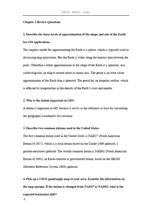
Chapter 2 Review Questions1. Describe the three levels of approximation of the shape and size of the Earth for GIS applications.The simplest model for approximating the Earth is a sphere, which is typically used in discussing map projections. But the Earth is wider along the equator than between the poles. Therefore a better approximation to the shape of the Earth is a spheroid, also called ellipsoid, an ellipse rotated about its minor axis. The geoid is an even closer approximation of the Earth than a spheroid. The geoid has an irregular surface, which is affected by irregularities in the density of the Earth’s crust and mantle.2. Why is the datum important in GIS?A datum is important in GIS because it serves as the reference or base for calculating the geographic coordinates of a location.3. Describe two common datums used in the United States.The first common datum used in the United States is NAD27(North American Datum of 1927), which is a local datum based on the Clarke 1866 spheroid, a ground-measured spheroid. The second common datum is NAD83(North American Datum of 1983), an Earth-centered or geocentered datum, based on the GRS80 (Geodetic Reference System 1980) spheroid.4. Pick up a USGS quadrangle map of your area. Examine the information on the map margin. If the datum is changed from NAD27 to NAD83, what is the expected horizontal shift?[The expected horizontal shift is listed on the lower margin of a USGS quadrangle map.]5. Go to the NGS-CORS website How many continuously operating reference stations do you have in your state? Use the links at the website to learn more about CORS.[Go to the above website, click a state on the map, and see how many continuously operating reference stations are within the state.] Surveyors, GIS professionals, engineers, scientists, and others can apply CORS data to position points at which GPS data have been collected. The CORS system enables positioning accuracies that approach a few centimeters relative to the National Spatial Reference System, both horizontally and vertically.6. Explain the importance of map projection.A map projection offers a couple of advantages. First, a map projection allows us to use two-dimensional maps, either paper or digital, instead of a globe. Second, a map projection allows us to work with plane or projected coordinates rather than longitude and latitude values. Computations with geographic coordinates are more complex and yield less accurate distance measurements.7. Describe the four types of map projections by the preserved property.A conformal projection preserves local angles and shapes. An equivalent projection represents areas in correct relative size. An equidistant projection maintains consistency of scale along certain lines. And an azimuthal projection retains certain accurate directions.8. Describe the three types of map projections by the projection or developable surface.A cylindrical projection uses a cylinder as the projection or developable surface, a conic projection uses a cone, and an azimuthal projection uses a plane.9. Explain the difference between the standard line and the central line.A standard line refers to the line of tangency between the projection surface and the reference globe. In other words, there is no projection distortion along a standard line. The central lines ., the central parallel and meridian) define the center of a map projection.10. How is the scale factor related to the principal scale?The scale factor is defined as the ratio of the local scale to the principal scale. In other words, the scale factor is the normalized local scale.11. Name two commonly used projected coordinate systems that are based on the transverse Mercator projection.They are the Universal Transverse Mercator (UTM) grid system and the State Plane Coordinate (SPC) system.12. Find the GIS data clearinghouse for your state in the Geospatial One-stop website Go to the clearinghouse website. Does the website use a common coordinate system for the statewide data sets? If so, what is the coordinatesystem? What are the parameters values for the coordinate system? And, is the coordinate system based on NAD27 or NAD83?[Go to the Geospatial One-stop website, click on State Links on the side bar, and then click a state clearinghouse website link. Typically the coordinate system information is included on the page for data download.]13. Explain how a UTM zone is defined in terms of its central meridian, standard meridian, and scale factor.A UTM zone is mapped onto a secant case transverse Mercator projection, with a scale factor of at the central meridian. The standard meridians are 180 kilometers to the east and west of the central meridian.14. Which UTM zone are you in? Where is the central meridian of the UTM zone?[The answer can be found on the margin of a 1:24,000-scale USGS topographic map. Figure 2.12 in the text can also provide the answer, but it is not as clear as on a USGS topographic map.]15. How many SPC zones does your state have? What map projections are the SPC zones based on?[Information on the SPC zones is available on the USGS topographic maps.]16. Describe how on-the-fly projection works.A GIS package, if it offers on-the-fly projection, can use the projection files available with the data sets and automatically convert the data sets to a common coordinatesystem. This common coordinate system is by default the coordinate system of the first data set in display.。


汽车专业英语 wheeled loading shovel 铲运机(electromagnetic )emission (电磁)发射A Cluster Of Gears 齿轮组A release Yoke 分离叉abdc(after bottom dead center) 下止点后above throttle valve EGR system 节气门前 EGR 系统ABS 制动防抱死系统Absolute Pressure Sensor 绝对压力传感器(APS)absorber lined chamber 尖劈absorber lined chamber 吸波室absorbing clamp 吸收钳absorbing material 吸波材料accelerated wear test 快速磨损试验accelerating pump nozzle 加速泵喷嘴accelerating pump 加速泵accelerating well 加速油井acceleration performance 加速性能Accelerator Pedal 加速踏板(AP)acceptance test 验收试验accident cause 事故原因Accommodate 容纳/供给accumulator fuel injection pump 蓄能式燃油喷射泵accuracy 精度acid tanker 酸罐车acoustic and noise 声学和噪声acoustic capacitance 声容acoustic feedback 声反馈acoustic hood 隔声罩acoustic impedance 声阻抗acoustic resonator 共鸣器acoustic spectrum 声谱acoustic wave 声波acoustical analysis 声学分析acoustical conductivity 传声性acoustical coupling 声藕合acoustical efficiency 声效率acoustical engineering 声学工程acoustical filter 滤声器acoustical frequency 声频acoustical instrument 声学仪器acoustical level 声级acoustical mass 声质量acoustical power 声功率acoustical radiator 声幅射器acoustical reactance 声抗acoustical resistance 声阻acoustics 声学acoustimeter 声强计、比声计Actuate 开动/使动/操纵adaptive coefficient 适应性系数adaptor carburetor 化油器附加器adjustment test 调整试验aerodynamic resistance 空气阻力after burner 后燃器After Top dead Center 上止点后(ATDC)aging test 老化试验Air Charge Temperature 进气温度(ACT)air cleaner and intake and exhaust sytem 空气滤清器及进排气系统Air Cleaner 空气滤清器(ACL)Air Condition Clutch 空调离合器(ACC)Air Conditioning 空调(A/C)air consumption 空气消耗率air cushion restraint system(ACRS) 空气垫约束系统air deflector 空气导流板air ducting 风道air filter cover 空气滤清器盖air filter housing 空气滤清器壳体air filter storage system 空气滤清器贮存装置air filter 空气滤清器Air Flow Control 空气流量控制(AFC)air flow measurement 空气流量测量Air Flow Sensor 空气流量传感器(AFS)air fuel ratio 空燃比Air Injection (二次)空气喷射(AI)Air Injection valve 空气喷射阀(AIV)air inlet shutter 进气节气门air jet 空气量孔air proportional EGR system 空气比例式 EGR 系统air shutter 关气机/调风门/ 空气阀 /阻汽器Air Temperature Sensor 空气温度传感器(ATS)airbag 气囊air-cooled engine 风冷式发动机aircraft caterer's delivery truck 航空食品装运车aircraft tractor 飞机牵引车air-fuel ratio feedback control system 空燃比反馈控制系统Air-Fuel Ratio 空然比all wheel drive automobile 四轮驱动车辆Alternator 交流发电机(ALT)altitude compensating carburetor 高海拔补偿式化油器altitude compensating 海拔补偿altitude control 海拔控制器ambient medium 环境介质ambinocular vision field 两单眼视野ambulance (medical vehicle) 救护车amplitude modulation (AM) 调幅amplitude resolution 幅值分辨率analogue magnetic recorder 模拟磁带记录器analysis by weight method 重量分析法analysis measuring method and instrument 分析测定方法和仪器analysis system 分析系统analytical train 成套分析设备Anchor Pins 副连杆销anechoic chamber 隔音室angled 成角度的annular float 环形浮子annular slot nozzle 环槽式喷嘴antenna 天线anterior -posterior axis 前后轴Anti-Lock Braking System 防抱死制动系统(ABS)antipercolator 反湿气装置Antiskid 防滑装置A-pillar A 立柱apparent frequency 视在频率approach angle 接近角approval test 鉴定试验Arduous 陡峭的/艰巨的area ratio of combustion chamber p assage 通道面积比arithmetic average 算术平均值Articulate 接合articulated bus 铰接客车articulated connecting rod 活节式连杆articulated road train 铰接式道路列车artificial hand 模拟手artificial network(AN) 人工(电源)网络artmobile 流动艺术展览车As The name implies 顾名思义asphalt distribution truck 沥青洒布车asphalt pavement maintenance truck 沥青路面养护车assembled camshaft 组合式凸轮轴assembled crankshaft 组合式曲轴assembly chain tension adjuster 链条张紧调节装置assembly cleanliness 装配清洁度Assembly Line Communication Link 总装线测试插座(ALCL)Assembly Line Diagnostic Link 总装线诊断插座(ALDL)Assembly 总成at idle 怠速时atdc(after top dead cetner) 上止点后atmospheric pressure compensating 气压补偿atmospheric pressure 大气压力Attach 附着/附属/相连attenuator 衰减器Audio System 音响系统auto crash simulation test sled 汽车模拟碰撞滑车试验装置autocorrelaton function analyzer 自相关仪automatic choke 自动阻风门automatic lubrication 自动润滑Automatic Transmission Fluid 自动变速箱油液(ATF)Automatic Transmission 自动变速automobile assembly drawing 汽车总装配图automobile noise 汽车噪声automobile ride random input running test 汽车平顺性随机输入行驶试验automobile ride single pulse input running test 汽车平顺性单脉冲输入行驶试验autothermic piston 抗热变形活塞auxiliary air-valve 辅助空气阀axial flow fan 轴流式风扇AXIAL FLOW TYPE CONVERTER 轴流式转化器axial-flow turbine 轴流式涡轮axle load 轴荷back flush 逆向清洗back of ring 活塞环内表面back pressure test 背压试验Backbone 脊骨/支柱/骨干Backlash 反冲back-leakage test 背部泄漏试验backplate 后挡板/护板Back-up Light 倒车灯Baffle Plate 隔板/挡板bag analysis 袋式分析bag tethers 囊加强带bag 囊balance gas 平衡气balancer weight 平衡重Balt Stud 球销/球关节balun 平衡-不平衡转化器banjo type drive axle 琴式驱动桥bare chassis dry mass 净底盘干质量(空重)bare chassis kerb mass 净底盘自重Barometric Pressure Sensor 大气压力传感器(BP)barrel type tappet 筒形挺杆barrel 柱塞套barrier 壁障base flanged mounted fuel injection pump 底部突缘安装燃油喷射泵base metal catalyst 普通金属催化剂Basis 基础/基本原理/根据bathtub section combustion chamber 浴盆形燃烧室Battery Positive Voltage 蓄电池正极(B+)bbdc(before bottom dead center) 下止点前Be Applied to 施加于/应用于Be Coupled with 与…连接be pilot 小批量产品Be Subject To 受到…,承受Bearing Journal 支承轴颈beer-lambert law 比尔-朗伯定律Before Top dead Center 上止点前(BTDC)belleville spring 蝶形弹簧below throttle valve EGR system 节气门后 EGR 系统belt restraint system 带约束系统belt tensioner 传动带张紧装置bench test 台架试验bevelled-ege oil control ring 边缘坡口油环beverage tanker 食品液罐车bi-conical antenna 双锥天线bidirectional coupler 双向藕合器binocular obstruction 双眼障碍binocular vision field 双眼视野biofidelity 仿真度biomechanical response 生物力学响应black smoke 黑烟bleeding pipe 通气管Blow 熔断/打击blowby gas 漏气blower casing 风扇壳体blower impeller 风扇叶轮blower stator 风扇导流定子body length 货厢全长body work length 车身长度bonfire test 火烧试验boost pressure 增压压力booster /enhancer 助燃剂/增强剂booster venturi 化油器小喉管Booster 助力器Boot 小客车后部行李厢/胎垫borderline lubrication 边界润滑bore and stroke 缸径与行程bore 内径Bottom dead Center 下止点(BDC)Bottom Dead Center下止点bowl cover 燃油泵盖boxed rod 方形连杆bracing piece 斜撑Brake Assemblies 制动器总成Brake Band 制动带/刹车带brake horse power 制动功率brake mean effective pressure(bmep) 制动平均有效压力brake specific emission 量比排放brake thermal efficiency 制动热效率Branch back 退回break bulk cargo carrier 厢式零担运输车breakdown truck(公路事故或故障车辆的)急修车Breakerless Electronic Ignition System 无触点电子点火系统Break-out Box 中断盒broadband amplifier 宽带放大器broadband artificial network (BAN) 宽频人工(电源)网络broadband emission 宽带(电磁)发射Bronze Bushes 青铜衬套(轴瓦)budc(before upper dead center) 上止点前built-in (in-line)smokemeter 内装式烟度计Built-In 内建的/内部的/内置的bulk container 散货集装箱bulk current injection (BCI) 电流注入bulk-calcium carbide pneumatic delivery tanker 气卸散装电石粉车bulk-cement pneumatic delivery tanker 气卸散装水泥车bulk-chemicals pneumatic delivery tanker 气卸散装化学粉粒车bulk-coal powder pneumatic delivery tanker 气卸散装煤粉车bulk-flour pneumatic delivery tanker 气卸散装面粉车bulk-fodder transport truck 散装饲料运输车bulk-grain carrier 散装粮食运输车bull dozer 推土机bumper 保险杠Bumper 保险杠/缓冲器/减震器burst of pulses 群脉冲burst test 爆破试验bus transfer 车辆转移台bus with front engine 发动机前置式客车bus with rear engine 发动机后置式客车bus with under floor engine 发动机中置式客车bus with underfloor engine 发动机底置式客车bus 客车Bus 总线/母线bush 轴套Bushings 轴套/轴瓦/衬套by-pass oil filter 分流式机油滤清器Bypass valve 分流阀/旁通阀cab 驾驶室Cable Boom 线架cadaver drop test 尸体跌落试验cadaver impact test 尸体冲击试验cadaver sled test 尸体滑车试验calculation for layout 总布置设计calibrating gas 校正气calibrating screen 标定用遮光片calibration gas 标定气体cam angle 凸轮包角cam contour 凸轮轮廓cam follower 凸轮从动件cam nose 凸轮尖cam-lobe lift 凸轮升程camshaft bearing bush seat 凸轮轴轴承座camshaft bearing journal 凸轮轴轴颈camshaft bearing 凸轮轴轴承camshaft drive 凸轮轴驱动机构camshaft drive(gear)cover 定时齿轮室罩camshaft eccentric 凸轮轴偏心轮camshaft fuel injection pump 凸轮轴式燃油喷射泵camshaft gear wheel 凸轮轴齿轮Camshaft play 凸轮轴端隙camshaft sprocket 凸轮轴链轮camshaft timing gear 凸轮轴正时齿轮camshaft 凸轮轴canister /catridge 金属盒canister purge line 碳罐净化管cantilever 飞轮芯棒car transporter 车辆运输车caravan 旅居挂车/大篷车carbon equivalent 碳数当量carbon monoxide percent by volume 一氧化碳容积百分率carbon monoxide 一氧化碳carburetor adaptor 化油器接头carburetor circuit 化油器系统carburetor engine 化油器式发动机carburetor 化油器carburetor 化油器/汽化器cargo trailer 栏板货厢式挂车cargo-bus 客货两用车cast inblock (cast enblock) 整体铸造catalyst attrition 催化剂耗损catalyst container 催化箱catalyst poisoning 催化剂中毒catalyst shrinkage 催化剂收缩catalyst 催化剂catalytic combustion analyzer 催化燃烧分析仪catalytic converter 催化转化器Catalytic Converter 触媒转换器/(汽车等的)催化式排气净化器/催化转化器(CAT)catalytic converting system 催化转化系统cellular radiator 蜂窝式散热器Cellular 蜂窝式的/多孔的centered 对中centimetric waves 超短波(厘米波)central engine 中置式发动机Central Fuel Injection 中央燃油喷射(CFI)Central Multiport Fuel Injection 中央多点燃油喷射(CMFI)central spindle 芯轴central-located connecting rod 中心曲柄连杆机构centrifuagl method 离心法Centrifugal fan 离心式风扇centrifugal fan 离心式风扇centrifugal governor 离心调速器centrifugal inertia force 离心惯性力centrifugal oil filter 离心式机油滤清器chain drive 链传动机构chain sprocket 链轮盘chain tension gear 链条张紧轮Chamfer 切角面/锥角Change Gear 换档Changeover 转变channel frequency classes 频率级通道Channel 通道/孔道/槽charcoal canister storage system 活性碳罐贮存装置charcoal canister 活性碳罐Charge 充电(CHG)charge 充量(进气)charging stroke 充气行程chart of automotive model 汽车型谱chassis and cab dry mass 底盘与驾驶室干质量(空重) chassis and cab kerb mass 底盘与驾驶室自重chassis dynamometer 底盘测功机chassis frame useful length 车架有效长度chassis shuttle 底盘平移台chemiluminescent detector 化学发光检测器choke button 阻风门拉钮choke cable 阻风门拉线choke heater 阻风门加热器choke opener 阻风门开启器choke piston 阻风活塞choke plate 阻风板choke tube 阻风管choke valve 阻风门chrome plated piston ring 镀铬活塞环Cigarette Lighter 吸烟点火器cinematographic procedure 电影摄影法Circuit Breaker 断路器Circuit 电路/回路/循环circulating pump 循环泵clamp 夹子/夹紧clean diesel 无公害柴油clean work area 局部洁净区cleaner 清洗液cleaning edge 刮片组件cleanliness limit 清洁度限值cleanliness measurement room 清洁度检测室clinic car 病院汽车Clog 阻塞closed car 厢式小客车Closed Loop 闭环(CL)closed nozzle 闭式喷嘴closed ring 闭合环closed spray chamber 封闭喷射室closed-crankcase ventilating system 闭式曲轴箱通风装置Clutch Pressure Control 离合器压力控制(CPC)co analyzer 一氧化碳分析仪coach 大客车Coast Clutch 单向离合器coastdown 滑行法coasting richer 强制怠速加浓装置Coasting 滑行/滑行距离/惯性运转coaxial cable 同轴电缆coefficient of excess air 过量空气系数coefficient of intensification 强化系数coefficient of light absorption (k) 光吸收系数coefficient of torque adaptibility 扭矩适应性系数coil spring loaded slotted oil control ring 螺旋弹簧加载双坡口油环Coil Spring 螺旋弹簧/圈弹簧cold manifold 冷式进气歧管collector 拼装台collision (crash,impact) 碰撞collision angle 碰撞角度collision axis alignment 碰撞轴线排列collision direction 碰撞方向color temperature 色温column 机柱Combination Meter 组合仪表combustion analyzer 燃烧分析仪combustion chamber volume 燃烧室容积Combustion Chamber 燃烧室commercial vehicle 商用车辆compact car 中级轿车compact diagnostic chamber 小型诊断室complete vehicle kerb mass 整车自重complete vehicle shipping mass 整车交运质量composite concentration of exhaust emission 综合排放浓度composite mass of exhaust emission 综合排放质量composite road train 混合式道路列车compound piston ring 组合式活塞环compressed natural gas vehicle 压缩天然气车辆compression chamber 压缩室compression ignition engine 压燃式发动机compression pressure 压缩压力Compression Rate 压缩比compression ratio 压缩比compression refuse collector 旋转板自装卸垃圾车Compression ring 压缩环/气环compression stroke 压缩行程comprex pressure wave supercharger 气波增压器computer aided deisgn(CAD) 计算机辅助设计Computer Controlled Coil Ignition 计算机控制点火(C3I)concave head piston 凹顶活塞Concave 凹的/凹面的concealed fastening 隐藏式固定concentration of emission 排放浓度concentric float 同心式浮子concentric piston ring 同心活塞环Concentric 同心的/同轴的concrete mixer truck 混凝土搅拌车condensate trap 凝水分离器Conical 圆锥形connecting rod bearing 连杆轴承connecting rod cap 连杆盖connecting rod shank 连杆杆身connecting rod small end 连杆小头connecting rod 曲柄连杆机构connecting rod 连杆connnecting rod big end 连杆大头constant clearance piston 不变间隙活塞constant pressrue exhaust manifold 等压排气歧管constant pressure cycle 等压循环constant purge line 恒量净化管constant volume cycle 定容循环constant volume sampling (CVS) 定容取样法constant volume unloading 等容卸载construction machinery transporter 工程机械运输车Contact 接触/连接container carrier 集装箱运输货车contaminate 玷污Contra-rotating rears 反转齿轮control linkage 控制杆系controlled combustion system 控制燃烧系统conversion efficiency 转化效率conversion factor 换算系数conversion factor 换算系数Conversion 转换/变换converter 转化器convertible saloon 活顶轿车Convex 凸的/凸面的/凸圆的coolant 冷却剂cooling air 冷却用空气cooling fin 散热片cooling recovery system 循环流冷却系cooling system 冷却系coordination system(axissystem) 坐标系corrected for CO2 extraction 二氧化碳干扰校正correction factor 校正系数correction factor 校正系数correction of motion 运动校核corrosion-resistance 抗腐蚀性Counter-ba;anced weight 平衡重量/平衡块coupe 小型轿车coupling path 藕合路径cradle mounted injection pump 框架安装式燃油喷射泵crane/lift truck 起重/举升汽车crank angle 曲柄转角Crank arm 曲柄臂crank pin 曲柄销crank 曲柄crankcase bleed pipe 曲轴箱通风管crankcase breather 曲轴箱通气口crankcase closed system 曲轴箱双通风系统crankcase door 曲轴箱检查孔盖crankcase emission control system 曲轴箱排放物控制系统crankcase emission 曲轴箱排放物crankcase explosion proof door 曲轴箱防爆门crankcase oil pan 曲轴箱机油油盘crankcase sealed system 曲轴箱单通风系统crankcase storage system 曲轴箱贮存装置Crankcase 曲轴箱crankshaft front end 曲轴前端crankshaft main journal 曲轴主轴颈crankshaft oil passage 曲轴油道Crankshaft Position sensor 曲轴位置传感器(CPS)crankshaft sprocket 曲轴链轮crankshaft thrust bearing 曲轴止推轴承crankshaft 曲轴Crash Sensor 碰撞传感器crash sensor 碰撞传感器crash simulation test set-up 撞车模拟装置crash site 撞车地点critical compression ratio 临界压缩比critical flow venturi 临界流量文杜里管cross head engine 十字头型发动机crossmodulation 交调crown head piston(convex head pist on) 凸顶活塞Cruise Control System 巡航控制系统current probe 电流探头cushion 垫cut-off cock 断油开关cylinder block and head 气缸体和气缸盖cylinder block fin 缸体散热片cylinder block frame 气缸体机架Cylinder Block 气缸体cylinder bore 缸径cylinder bore 缸径cylinder capacity 气缸容量cylinder clearance volume 气缸余隙容积cylinder fuel-cut test 停缸试验cylinder head fin 缸盖散热片cylinder head gasket 气缸盖垫片cylinder head ring gasket 气缸盖密封环cylinder head 气缸盖Cylinder Identification Sensor 气缸传感器(CID)Cylinder Jacket 气缸套cylinder liner(cylinder sleeve) 气缸套cylinder spacer 气缸体隔片cylinder variation test 各缸工作均匀性试验cylinder wall 气缸壁cylindrical fuel injection pump 圆柱式燃油喷射泵dampling chamber 阻尼室dash board 仪表板Dashboard 仪表板/车辆的挡泥板Data Link Connector 数据传递插接器(DLC)data processing 数据处理dead center 止点dead volume 死区容积deceleration control system 减速控制装置deceleration sled 座椅deceleration spark advance control 减速点火提前控制装置decibel(dB) 分贝declared working condition 额定工况Deflection 挠曲/变形/变位deflector 导流板DEFOG 除霜Defogger System 除雾器系统deformation 变形Deformation 变形/扭曲/畸变/失真degradation of performance 性能降低degree wheel 角度轮deliver 运送/输送/传递delivery ratio 给气比delivery test 出厂试验delivery valve 输出阀Delta 增量demonstration car 展览汽车demountable tanker carrier 背罐车departure angle 离出角derating power 减额功率derrick transporter 井架运输车Descending 下行/下降/向下desensitization 灵敏度降低design assignment 设计任务书design for finite life 有限寿命设计detector 检波器deterioration factor(DF) 劣化系数(DF)Detonation Sensor 爆燃传感器(DS)developing V points and P points 派生 V 点和 P 点device for power absorption 功率吸收装置device under test(DUT) 在试设备diagnosis and alarming system 诊断报警系统Diagnostic Truble Code 诊断故障代码(DTC)diagnostic module 诊断组件Diagnostic test mode 诊断测试模式(DTM)diagonal safety belt 腰带式安全带diaphragm fuel supply pump 膜片式燃油泵diesel cycle 狄塞尔循环diesel engine 柴油机diesel gas engine 柴油煤气机diesel smoke measuring instrument 柴油机排烟测定仪器diesel smoke 柴油机排烟Differential 差速器 (DIFF)diffused light 散射光diffuser (inflator) 增压器digital chronometer 数字计时器digital magnetic recorder 数字式磁带记录器digitalisation 数字化diluted exhaust 稀释排气dilution air 稀释用空气dilution factor 稀释系数dilution tunnel 稀释风道dilution 稀释Diminish 减少/缩小/衰减dipole antenna 偶极子天线dipstick 机油量尺Dipstick 油尺/水(油)位指示器Direct Fuel Injection 直接燃油喷射(DFI)direct injection engine 直接喷射式柴油机direct light ray 直接光线direct sampling method 直接取样法direct valve gear 直接式气门驱动机构direct vesion field 直接视野direct-cooled piston 直接冷却式活塞direction of principal force(PDOF) 主要力方向direction of rotation 旋转方向directional coupler 定向藕合器dirty solution 混浊液disassembly cleanliness 解体清洁度Discharge Warning Light 放电警告灯Disengage 解开/使脱离Disengagement 释放/脱离/断开displacement 排气量/气缸工作容积displacement 排气量display surface 显示表面distance between jaw and front end of towing vehicle 牵引叉销至车辆前端的距离distance between towing device and front end of towing vehicle 牵引装置至车辆前端的距离distance of towing attachment 牵引装置牵距distortion index 失真指数Distortion 扭曲/变形distributor fuel injection pump 分配式燃油喷射泵Distributor Ignition 分电器点火(DI)Distributorless Ignition 无分电器点火(DLI)distrubance source 干扰源disturbance field strength 骚扰场强disturbance power 骚扰功率disturbance suppression 骚扰抑制diurnal breathing losses 昼间换气损失divided combustion chamber 分开式燃烧室dome head piston 圆顶活塞dominant 支配的/统治的door height 门高Door Lock Control System 门锁控制系统door width 门宽doppler effect method 多普勒效应法dosage valve piston 剂量阀活塞double & triple venturi 双重或三重喉管double bevelled oil control ring 双坡口油环double road train 双挂式道路列车Double-Acting Vane pump 双作用式叶片泵double-deck bus 双层客车down flow type converter 下流式转化器down stroke 下行程downdraught carburetor 下吸式化油器Downshift 减速downtime 停机时间downwards angle of visibility 下视角drag 牵引/拉/制动/障碍物/阻力drain plug 放油螺塞drain valve 排水阀Drainage 排水系统drawbar length 牵引杆长dribble 滴油drift 漂移Drive line 动力传递系统/驱动系统Drive Shaft Brakes 驱动轴制动器driver aid 行驶监视仪driveshaft fuel injection pump 驱动轴式燃油喷射泵driving cycle 行驶循环Driving Stability 操纵稳定性drop head coupe 敞蓬小轿车drop test 跌落试验dry cargo container 干货集装箱dry cylinder liner 干式缸套dual bed converter 双床式转化器dual -catalyst system 双重催化系统dual engine drive 双发动机并联传动dual overhead camshaft engine 双顶置凸轮轴发动机dual valve 双气门duct 通风口Due To High Mileage 由于长途行驶duel fuel engine 双燃料发动机duel fuel vehicle 双燃料车辆dummy lamp 模拟灯dummy 假人dumper trailer 自卸式挂车durability test 耐久性试验Duralumin 硬铝/杜拉铝dust car (refuse collector) 垃圾车dynamic balancer 动平衡机dynamic or continuous sampling 动态或连续取样法dynamic phase 动态相位Dynamic 动态的/不断变化的dynamometer 测功机e-/h-generator 电场/脉冲发生器earth-coupled interference 地藕合干扰eccentric piston ring 偏心活塞环eccentric shaft 偏心轴ECE 15-mode test cycle 欧洲ECE 十五工况法economic speed 经济转速economizer valve 省油器阀economizer 省油器eddy current dynamometer 电涡流测功机edible oil pump delivery tanker 食用植物油加油车edible oil tanker 食用植物油运油汽车effective filter area 滤纸有效面积effective interpupillary width 有效瞳孔距effective length 有效长度effective optical path length(L) 光通道有效长度effective path length of light ray 光线有效通过长度effective stroke 有效行程effective thermal efficiency 有效热效率EGR control valve EGR 控制阀EGR cooler EGR 冷却器EGR gas 再循环排气EGR pressure regulator EGR 调压阀EGR rate 再循环排气率EGR system 排气再循环系Elaborate 复杂的/精心制作的Elasticity 伸缩性/弹性electric dynamometer 电力测功机electric vehicle 电动车辆electric wheel 电动轮Electrical Load detector 电子负载检测器(ELD)electrical response time 电气响应时间electrical transmission 电传动electric-assisted choke 电控自动阻风门electromagnetic beam barrier 电磁束栏障electromagnetic compatibility(EMC) 电磁环境兼容性electromagnetic disturbance 电磁骚扰(现象)electromagnetic environment 电磁环境electromagnetic interference 电磁干扰electromagnetic interference 电磁干扰试验electromagnetic noise 电磁噪声electromagnetic radiation 电磁辐射electromagnetic susceptibility(EMS) 电磁敏感度electromagnetic waves 电磁波Electronic Automatic Transmission 电控自动变速器 (EATX)electronic concentrated engine control system 发动机电子集中控制系统Electronic Control Assembly 电子控制总成 (ECA)Electronic Control Sestem电控系统Electronic Control Unit 电控单元electronic controlled carburetor 电子控制化油器electronic controlled EGR system 电子控制式 EGR 系统electronic crash sensor 电子碰撞传感器electronic fuel injection system 电子燃油喷射系统Electronic Fuel Injection 电控燃油喷射 (EFI)Electronic Fuel metering System 电子燃油计量系统electronic indicator 电子示功仪electronic pieces 电子器件electrostatic discharge(ESD) 静电放电elementary carburetor 简单化油器emission排放/排放物emission concentration limits 浓度排放限值emission control system 排放物控制系统emission factor 排放系数emission index 排放率emission limits 排放限值emission performance 排放性能emitted frequency 发射波频率end flange-mounted fuel injection pump 端部突缘安装式燃油喷射泵end outline 前视轮廓energizing spring 上紧弹簧energy chamber 空气室Engine Control 发动机控制 (EC)engine block stiffening rib 气缸体加强筋engine bonnet 发动机罩Engine Coolant Temperature Sensor 发动机水温传感器(CTS)engine displacement 发动机排量engine holding frame 发动机托架engine performance 发动机性能engine speed (rotational frequency) 发动机转速engine technical requirements 发动机技术要求engine test bed 发动机试验台engine test procedure 发动机试验规程engine test 发动机试验envelope 包容线environmental simulation test 环境模拟试验equivalent inertia 当量惯量equivalent shaft length 当量轴长equivalent system 当量系统estate car (estate) 客货两用小客车evaporative emission control system 蒸发排放物控制系统evaporative emission 蒸发排放物Excess Air ratio 过量空气系数excess fuel device 加浓器exchange-compression stroke 换气压缩行程Exciter 激励器/励磁机/激活剂exhaust advance angle 排气提前角exhaust analysis test 排气分析试验exhaust back pressure 排气背压exhaust cam 排气凸轮exhaust crossover 排气横跨管道exhaust emission control system 排气排放物控制系统exhaust emission suction system 废气排气系统exhaust extraction duct 排气抽气管Exhaust gas analyzer 废气分析仪exhaust gas collection equipment 排气收集系统Exhaust Gas Oxygen Sensor 氧传感器 (EGOS)Exhaust Gas Recirculation 废气再循环 (EGR)exhaust gas recirculation 排气再循环exhaust -gas-recirculation 排气再循环阀exhaust heat loss 排气热损失exhaust lag angle 排气滞后角exhaust manifold heat control valve 排气歧管热量控制阀exhaust manifold 排气歧管Exhaust pipe 排气管exhaust port liner 排气口衬套exhaust port 排气口exhaust pressure controlled EGR system 排气压力控制式 EGR 系统exhaust purification 排气净化exhaust silencer 排气消声器exhaust smoke 排气烟度exhaust stroke 排气行程exhaust valve lifter 排气门挺杆exhaust 排气Exhaust 排气 (EX)expander 涨环Expander 膨胀器/扩张器expansion plug 膨胀塞expansion ratio 膨胀比expansion stroke 膨胀行程expansion tank 涨溢箱expansion-exchange stroke 膨胀换气行程explosion chamber 爆发室explosion stroke 爆炸行程external immunity 外部抗扰性extra heavy off- road vehicle 超重型越野车eye point (E point) 眼点(E 点)eyellipse center 眼椭圆中心eyellipse locating line 眼椭圆定位线eyellipse template 眼椭圆模板eyellipse 眼椭圆factor of weight utilizaton 重量利用系数Fade 逐渐失灵/衰减/减弱/调节器fairground vehicle 博览会专用车fan blade 风扇叶片Fan Control 风扇控制 (FC)fan cowl 风扇导流罩fan hub 风扇毂fan pulley 风扇皮带轮fan shroud 风扇护罩fan(blower) 风扇farm vehicle 农用车fatal and severe accidenet 死亡和重伤事故feed pump 输油泵Feed 供应feedback control 反馈控制fender 翼板F-engine F 形发动机fft analyzer FFT——快速傅里叶变换)分析仪fiber optic links 光导纤维电缆field generator 场强发生器field monitoring equipment 磁场控制器field strength 磁场强度field test 现场试验field 磁场fifth wheel lead for calculation of length 长度计算用牵引座前置距fifth wheel lead for calculation of mass distribution 质量分配用牵引座前置距fifth wheel lead 牵引座(转向轮)前置距fifth wheel method 五轮仪法fifth wheel method 第五轮仪fill control system 注油控制装置filler tube 加油管fillet 圆角film analysis system 胶片分析仪film core 之字形管散热器芯film projection vehicle 电影放映车filter assembly 过滤器总成filter box 滤清器壳filter cell 滤光室filter element 滤清器滤芯filter membrance 滤膜filter paper disc or membrane 滤纸盘或膜filter seal ring 滤清器密封圈filter shaft 滤芯轴filter smoke number (FSN) 滤纸式烟度单位filter type smokemeter 滤纸式烟度计Filter 过滤器/滤清器filtering disc 滤片filtering 滤波filter-type measuring apparatus 滤纸式测试仪filtration 过滤fin and tube core 管-片式散热器芯Fin 散热片/(铸件)周缘翅片final assembly 总装finned radiator 片式散热器fire extinguishing system 消防系统fire pumper 救火泵车fire service commanding car 消防指挥车fire tanker 消防水罐车fire 火灾fire-extinguishing foam tanker 泡沫消防车fire-extinguishing water tanker水罐消防车fire-fighting truntable ladder 云梯消防车fire-fighting vehicle 消防车fixed venturi carburetor 固定喉管式化油器flame ionization ditector 氢火焰离子化检测器flanged-mounted injection nozzle holder 突缘安装喷油器壳体flat head piston 平顶活塞flat platform trailer 平板式挂车flat rack container 框架集装箱Flat 平的/平坦的float arm 浮子臂float hinge pin 浮子支销float level 浮子油面float needle valve 浮子针阀float system 浮子系float 浮子floating coat 中涂flood lighting vehicle 照明车flowmeter 流量计flyball governor 飞球式调速器flyweight 提前器飞锤flywheel cover 飞轮壳flywheel mark 飞轮标记flywheel moment of inertia 飞轮的惯量矩flywheel ring gear 飞轮齿圈flywheel spindle 飞轮芯轴flywheel stored energy transmission system 飞轮蓄能传动系foam vehicle 泡沫灭火车Fog Light System 雾灯系统forced exhaust 强制排气forced lubrication 压力润滑法forced-air cooling 强制风冷forced-feed water circulation system 强制循环式化冷系统fork-and-blade connecting rod 叉形连杆fork-type loading (unlaod)machine 叉式装货机forward control passenger car 短头轿车four-barrel carburetor 四腔化油器four-stroke cycle 四冲程循环frame free length 车架自由长度free acceleraton method 自由加速法free exhaust 自由排气free ring 自由环freeze plug 防冻塞frequency step sizes 频率级规格frequency analyzer 频率分析仪frequency response test 频率响应时间试验frequency response 频率响应fresh charge 吸入的新鲜混合气front drive automobile 前驱动汽车front exhaust pipefront fitting radius of semi-trailer 半挂车前回转半径front overhang 前悬front wall angle cover 前围角板frontal collision (frontal impact) 正碰撞front-engine 前置式发动机fuel and vapor separator 油气分离器fuel consumption 燃油消耗量fuel control system 燃油控制系统fuel control unit 油量调节装置fuel delivery per cycle 循环供油量fuel delivery 供油量fuel discharge port 出油口接头fuel equivalence ratio 燃料当量比fuel feed hole 进油孔fuel filter 燃油滤清器fuel gallery 燃油通道fuel gauge 燃油表Fuel Injection Air 燃油喷射进气 (FIA)fuel injection beginning 喷油始点fuel injection duration angle 喷油持续角fuel injection end 喷油终点fuel injection equipment 燃油喷油装置Fuel Injection 燃油喷射fuel inlet neck 进油口接头fuel level gauge 油位表Fuel Lid Opener System 燃油加油口盖开启系统fuel pump base 燃油泵下体fuel pump body 燃油泵上体fuel pump 燃油泵fuel return valve assembly 回油阀部件fuel supply advance angle 供油提前角fuel supply rate curve 供油规律fuel supply rate 供油率fuel system 供油系fuel tank check valve 燃油箱止回阀fuel tank 燃油箱fuel tanker 运油车fuel vapor recovery system 燃油蒸气回收系统Fulcrum 支点/支轴/支柱full flow opacimeter 全流式烟度计full flow sampling 全流取样法full load method 全负荷法full load 全负荷full range A/C 全天候空调系统full scale 全量程full trailer 全挂车full-floating piston pin 全浮式活塞销full-flow oil filter 全流式机油滤清器full-flow smokemeter 全流式烟度计full-trailer towing vehicle 全挂牵引汽车function performance status classificaton (FPSC) 功效性能状况分类fundamental (component) 基波(分量)galvanized plate 镀锌板gas chromatograph 气相色谱仪gas composition test 气体成分试验gas engine 煤气机gas exchange process 换气过程gas generant 气体发生剂gas tightness 气密性gaseous pollutant 排气污染物gasoline engine 汽油机gasoline feed pipe 汽油供给管gasoline tank( petrol tank) 汽油箱gasoline-injection engine 汽油喷射式汽油机gas-tight collection bag 不透气收集袋Gauge 仪表gear Shift Mechanism 换档机构gear drive 齿轮传动机构gear fuel supply pump 齿轮式输油泵Gear Train 齿轮传动系gear type oil pump 齿轮式机油泵general -purpose vehicle 通用货车generating radius 创成半径(转子机)geometric fuel delivery stroke 几何供油行程GER filter EGR 过滤器glass pack muffler 玻璃丝消声器Globoid 球状的/球状体governor control characteristics 调速特性governor weight 调速器重锤governor 调速器grade ability 爬坡能力grain of the film 胶片颗粒gravity circulation water cooling system 温差循环液冷却系统Grease Fitting 黄油嘴grit test method 磨料试验法。
第39卷第1期2016年2月测绘科学与工程Geomatico Science and EneieeerineVol.39,No.1Feb.,2019国际地球参考框架ITRF2214评析明锋82,曾安敏8,1.西安测绘研究所,陕西西安,710054;2.地理信息工程国家重点实验室,陕西西安,710054摘要:国际地球自转服务组织IERS于2016年1月22日发布了最新的国际地球参考框架ITRF2014。
相对于ITRF008,ITRF014在测站坐标运动学模型中增加了两个非线性项,即季节项和震后形变。
由于更加精g地描述了测站的位移,ITRF014的精度要优于ITRF2008。
然而,ITRF014的函数模型增加了新的季节项参数,且季节项参数与转换参数线性相关。
因此,框架实现时必须对新增加参数施加对应的约束条件。
不同的约束方式会导致不同的ITRF实现。
本文详细介绍了国际地球参考框架建立中的基本理论概念,回顾了建立框架时可能用到的各种约束方式,对ITRF2014所用的坐标运动模型进行了分析,并对其季节性信号存在的问题进行了评述。
关键词:国际地球参考框架;最小约束;内约束;坐标运动模型;ITRF2014中图分类号:P28文献标志码:A文章编号:2092-4527(2016)01-0016-10大地测量的主要任务是尽可能准确地确定地球表面点的位置。
然而,由于点的位置既不具有观测性也不是绝对数值,因而它们必须相对于某些其它外部参考来唯一确定。
通常选择一组具有精确坐标的物理实点用来作为地球参考系统的物理实现,通过这些点的坐标间接地获得了参考系的坐标轴。
这组坐标及其统计指标即构成地球参考框架o严格来说,地球参考系统(Terrestrial Reference System,TRS)、地球参考框架(Terrestrial Reference Frame,TRF)以及坐标系统(Coordinate System)是三个不同层次的概念。
SensorBus:AnIntermediaryLayerforLinkingGeosensorsandtheSensorWeb
ArneBroeringInternationalInstituteforGeo-InformationScienceandEarthObservation(ITC)UniversityofTwenteEnschede,Netherlandsbroering@52north.orgTheodorFoersterInstituteforGeoinformatics(IfGI)UniversityofMünsterMünster,Germanytheodor.foerster@uni-muenster.deSimonJirka52◦NorthInitiativeforGeospatialOpenSourceSoftwareMünster,Germanyjirka@52north.org
CarstenPriessInstituteforGeoinformaticsUniversityofMünsterMünster,Germanycarsten.priess@uni-muenster.de
ABSTRACTInrecentyears,thestandardsofOGC’sSensorWebEn-ablement(SWE)initiativehavebeenappliedinamulti-tudeofprojectstoencapsulateheterogeneousgeosensorsforweb-baseddiscovery,taskingandaccess.Currently,SWEservicesandthedifferenttypesofgeosensorsareintegratedmanuallyduetoaconceptualgapbetweenthesetwolayers.Pair-wiseadaptersarecreatedtoconnectanimplementa-tionofaparticularSWEservicewithaparticulartypeofgeosensor.ThisapproachiscontrarytotheaimofreachinginteroperabilityandleadstoanextensiveintegrationeffortinlargescalesystemswithvarioustypesofgeosensorsandvariousSWEserviceimplementations.
ToovercomethisgapbetweengeosensornetworksandtheSensorWeb,thisworkpresentsanintermediarylayerforintegratingthesetwodistinctlayersseamlessly.Thisinter-mediarylayeriscalledtheSensorBusasitisbasedonthemessagebusarchitecturepattern.ItreducestheeffortofconnectingasensorwiththeSWEservices,sinceonlytheadaptiontotheSensorBushastobecreated.Thecom-municationinfrastructurewhichactsasthebasisfortheSensorBusisexchangeable.Inthiswork,theSensorBusisbasedonTwitter.TheinvolvedSWEservicesaswellasconnectedgeosensorsarerepresentedasuserprofilesoftheTwitterplatform.
CategoriesandSubjectDescriptorsH.4[InformationSystemsApplications]:Communica-tionsApplications;D.2[SoftwareEngineering]:Software
ArchitecturesKeywordsSensorWeb,geosensornetworks,SWE,Twitter
1.INTRODUCTIONNowadays,sensorsbecomesmaller,cheaper,morereliable,morepowerefficientandmoreintelligent.Geosensors,askindsofsensorsdeliveringanobservationwithgeoreferencedlocation[33],areincreasinglyusedinvariousapplicationsrangingfromenvironmentalmonitoring,precisionagricul-turetoearlywarningsystems[29].Thesensorsutilizedintheseapplicationsmaybestationaryormobile,eitheronland,waterorintheairandcouldgatherdatainanin-situorremotemanner.Duetothisvariety,acoherentinfras-tructurehasbecomenecessarytointegrateheterogeneoussensorsinaplatformindependentanduniformway.TheSensorWebissuchaninfrastructureforsharing,findingandaccessingsensorsandtheirdataacrossdifferentappli-cations[25].TheSensorWebistosensorswhattheWorldWideWeb(WWW)istogeneralinformationsources-aninfrastructureallowinguserstoeasilysharetheirsensorre-sources.Ithidestheunderlyinglayerswiththenetworkcommunicationdetails,andheterogeneoussensorhardware,fromtheapplicationsbuiltontopofit.
TheSensorWebEnablement(SWE)[5]initiativeoftheOpenGeospatialConsortium(OGC)1standardizesWebSer-viceinterfacesanddataencodingsfortheSensorWeb.Inrecentyears,theseSWEstandardshavedemonstratedtheirpracticabilityandsuitabilityinvariousprojects(e.g.,[10,27,19,34])andapplications(e.g.,[15,1,8,14]).How-ever,duetothemissinginteroperabilitybetweenthetwolayers(geosensornetworkandSensorWeb),itiscurrentlynotpossibletodynamicallyinstallgeosensorson-the-flywithaminimumofhumanconfigurationeffort,toenableaplug&playofgeosensors.
1http://www.opengeospatial.org
Permission to make digital or hard copies of all or part of this work for personal or classroom use is granted without fee provided that copies are not made or distributed for profit or commercial advantage and that copies bear this notice and the full citation on the first page. To copy otherwise, to republish, to post on servers or to redistribute to lists, requires prior specific permission and/or a fee.
COM.Geo 2010, June 21-23, 2010 Washington, DC, USA Copyright 2010 ACM 978-1-4503-0031-5...$10.00. DynamicallyinstallinggeosensorsontheSensorWebinaplug&playmannerrequiresadvancedconcepts.Gener-ally,theSWEstandardsfocusoninteractingwiththeupperapplicationlevel.Theyaredesignedfromanapplication-orientedperspective.Asaresult,theinteractionbetweentheSensorWebandtheunderlyinggeosensornetworklayerhasnotbeensufficientlydescribedyet.TheSensorWebisbasedontheWWWanditsrelatedprotocols.Ontheotherhand,sensornetworktechnologiesarebasedonlower-levelprotocolssuchasBluetooth2,ZigBee3,theIEEE1451stan-dardsfamily[21]orproprietaryprotocols.Fromanappli-cationperspective,theSWEservicesencapsulatethesensornetworkandhidetheselower-levelprotocols.Currently,theSensorWebandgeosensornetworklayerareintegratedbymanuallybuildingproprietarybridgesforeachpairofWebServiceimplementationandsensortype.Thisapproachiscumbersomeandleadstoextensiveadaptioneffort.Sincethepriceofsensordevicesisdecreasingrapidly,theman-ualintegrationbecomesthekeycostfactorindevelopinglarge-scalesensornetworksystems[3].Conceptsaremiss-ingwhichfacilitatetheconnectionofthetwolayers.AftergivinganoverviewoftheSWEstandards(Section2)andrelatedwork(Section3),theconceptofanintermediarylayerbetweenSensorWebandgeosensornetworklayer,theSensorBus,isdescribed(Section4).Inanextstep(Section5)theSensorBusisimplementedbytheexampleofTwitterfollowedbyananalysisofthisimplementation(Section6).Thepaperendswithaconclusionanddiscussionoffuturework.2.SENSORWEBENABLEMENTTheOGCisanindustryconsortiumcomprisingover380membersdefininginteroperableservicesfortheGeospatialWeb.TheSWEinitiative[5]aspartofOGC’sspecifica-tionprogramdevelopsstandardstointegratesensorsintotheGeospatialWeb.Inparticular,SWEincorporatesdatamodelsfordescribingsensors(SensorML[4])aswellasgath-eredsensordata(Observations&Measurements[11]).ThemainWebServiceinterfacesaretheSensorObservationSer-vice(SOS),theSensorAlertService(SAS),andtheSensorPlanningService(SPS).TheSWEstandardsframeworkcanbeusedtosetupaSensorWeb.TheSOS[24]isdesignedforaccessingrealtimeaswellashistoricsensordata,andsensormetadata.Itsoperationsallowuserstorequestsensordatabasedonspatial,tem-poralandthematicfiltercriteria.Additionally,theSOSoffersoperationsforinsertingobservationsandsensors.Re-questedsensordataareencodedconformingtotheObser-vations&MeasurementsstandardandthesensormetadataarereturnedasSensorMLdocuments.AcomplementaryapproachforaccessingsensordataisofferedbytheSAS[31].WhiletheSOSfollowsthepull-basedcommunicationparadigm,theSASiscapableofpushingsensordatatosub-scribers.SubscribersoftheSASdefineparticularalertcon-ditionstospecifythesituationstheyareinterestedinandwanttoreceivedataaccordingly(e.g.,whensensorxmea-surestemperatureover30◦C).TocontrolandtasksensorstheSPS[32]canbeused.AcommonapplicationofSPS2http://www.bluetooth.org3http://www.zigbee.orgistodefinesimplesensorparameterssuchasthesamplingratebutalsotodefinemorecomplextaskssuchasmissionplanningofsatellitesystems.Furtheron,theSPSoffersabroadrangeofoperationsformanagingsubmittedsensortasks(e.g.,deleting,updatingandcancelingtasks).