TenFold Enterprise Installation Guide
- 格式:pdf
- 大小:600.76 KB
- 文档页数:12
OMNITREND®Center安装和启用版本:2.7.1版的:2022/8/24文件编号:LIT82.201.ZH翻译手册翻译本文档的信息可能在无事先告知的情况下发生更改。
本文档中介绍的软件在提供时附有许可证协议。
只有在符合本协议中包含的条件时,才允许复制软件。
本文档或其片段未经PRÜFTECHNIK批准,不得印刷或以其他方式复制。
Fluke.OMNITREND是PRÜFTECHNIK AG的注册商标。
©Fluke.保留所有权利Fluke Deutschland GmbH85737Ismaning(德国)目录1引言51.1欢迎使用OMNITREND Center51.2开始前61.3安全81.4售后服务地址91.5系统条件102安装112.1安装服务器112.2配置服务器122.3准备服务器模块152.4启动/停止服务器162.5安装客户端182.6安装单机版192.7更新203启用213.1启动客户端/单用户应用213.2与服务器建立连接223.3中断/断开与服务器的连接233.4激活OMNITREND Center244索引27 OMNITREND Center│安装和启用3空白页1引言1.1欢迎使用OMNITREND CenterOMNITREND Center是一款新开发的状态监测软件,用于监测和诊断旋转设备的运行状态。
OMNITREND Center可对用普卢福公司(PRÜFTECHNIK AG)推出的便携式状态监测系统(如测量数据采集系统)或固定安装式状态监测系统(如在线设备)记录的设备园区的状态数据进行处理。
OMNITREND Center拥有丰富的实用分析功能,可帮助分析测量数据。
所有结果均以报告和调查结果形式进行记录和存档,令人一目了然。
在软件内,可借助测量模板和设备模板对状态监测系统进行配置,以便采集测量数据。
OMNITREND Center│安装和启用5安装和启用1.2开始前检查供货范围到货时请检查货物是否有受损件或缺失件。
2012 Moxa Inc. All rights reserved.P/N: 1802053080013 TN-5308Hardware Installation GuideMoxa ToughNet SwitchFourth Edition, May 2013OverviewThe ToughNet TN-5308 series M12 unmanaged Ethernet switches are designed for industrial applications in harsh environments. The TN series switches use M12 connectors to ensure tight, robust connections, and guarantee reliable operation against environmental disturbances, such as vibration and shock. The TN-5308 series Ethernet switches provide 8 Fast Ethernet M12 ports, support IEEE 802.3/802.3u/802/3x with 10/100M, full/half-duplex, MDI/MDI-X auto-sensing, and provide an economical solution for your industrial Ethernet network. Models with an extended operating temperature range of -40 to 75°C are also available. TheTN-5308 series Ethernet switches are compliant withEN50155/50121-3-2/50121-4 standards for railway applications. Package ChecklistYour TN-5308 is shipped with the following items. If any of these items is missing or damaged, please contact your customer service representative for assistance.•Moxa ToughNet Switch•Panel Mounting Kit•Hardware Installation Guide•Moxa Product Warranty StatementFeaturesHigh Performance Network Switching Technology•8 10/100BaseT(X) ports•Store and Forward switching process type•IEEE 802.3/802.3u/802.3x•10/100M, Full/Half-Duplex, MDI/MDIX auto-sensingIndustrial-Specific Applications•Support 12/24/36/48 VDC (7 to 60 VDC) power input for “-LV”models•Support 72/96/110 VDC (50.4 to 154 VDC) power input for “-MV”models•Active circuit protectionRugged Design•M12 / M23 circular connectors for vibration-resistant robust connections•Operating temperature range of 0 to 60°C, or extended operating temperature range of -40 to 75°C for “-T” models•IP40, rugged metal housing•Panel mounting or DIN-rail mounting installation capability1.TP port’s 10/100 Mbps LED2.10/100BaseT(X) port(female 4-pin shielded M12 connector with D coding)3.Port label4.Screw holes for panel mounting kit or DIN rail mounting kit(there are 3 holes: top middle, bottom left, and bottom right)5.Power input LED6.Power input port(male 6-pin shielded M12 connector with A coding)7.Grounding screw8.Power input port pin assignment9.Model name10.TP port pin assignment11.Model label1.TP port’s 10/100 Mbps LED2.10/100BaseT(X) port(female 4-pin shielded M12 connector with D coding)3.Port label4.Screw holes for panel mounting kit or DIN rail mounting kit(there are 3 holes: top middle, bottom left, and bottom right)5.Power input LED6.Power input port(male 6-pin shielded M23 connector with A coding)7.Grounding screw8.Power input port pin assignment9.Model name10.TP port pin assignment11.Model labelMounting Dimensions (unit = mm) TN-5308-LVTN-5308-MVPanel/Wall MountingMounting the TN-5308-LV/MV on the wall requires 3 screws. Please use the 3 screws packed in the panel mounting kit.STEP 1: Prepare the 3 screw holes on the wall according to the positions of the 3 screw holes on the switch shown on the mounting dimension diagram.STEP 2: Use one screw to go through the top-middle screw hole on the switch and screw it into the wall.STEP 3: Screw in the remaining 2 screws through the bottom-left and bottom-right holes on the switch to the wall.NOTE The screw lengths of TN-5308-LV and TN-5308-MV are different. TN-5308-LV uses M3 * 30 mm screws. TN-5308-MV uses M3 * 40 mm screws. Please use the screws packed in the panel mounting kit.DIN-Rail Mounting (optional)With the optional DIN-Rail mounting kit DK-TN-5308 (must be purchasedseparately), you can mount the TN-5308-LV/MV on a 35mm DIN-Rail.STEP 1:Fix the DIN-Rail attachment plate onto the rear panel of the switch as shown in the figure at the right.STEP 2:Position the TN-5308-LV/MV on the DIN-Rail, tilting to hook clamps over the top edge of the rail. STEP 3:Swing the switch down fully onto the DIN-Rail until both clamps completely latch.To remove the Moxa ToughNet Switch from the DIN-Rail, simply reverse Steps 2 and 3 above.Wiring RequirementsPlease read and follow these guidelines:•Use separate paths to route wiring for power and devices. If power wiring and device wiring paths must cross, make sure the wires are perpendicular at the intersection point.•NOTE: Do not run signal or communications wiring and power wiring through the same wire conduit. To avoid interference, wires withdifferent signal characteristics should be routed separately.•You can use the type of signal transmitted through a wire to determine which wires should be kept separate. The rule of thumb is that wiring that shares similar electrical characteristics can bebundled together.•Keep input wiring and output wiring separated.•It is strongly advised that you label wiring for all devices in the system when necessary.Grounding the TN-5308Grounding and wire routing help limit the effects of noise due to electromagnetic interference (EMI). Run the ground connection from the grounding screw to the grounding surface prior to connecting devices.Connecting the Power SupplyThe M12 A coded 5 pin and M23 6 pin male connector on theTN-5308-LV/MV front panel is used for the DC power input. You have to prepare a power cord with M12/M23 A-coded 5-pin female connector to connect the switch to the DC power input.Pinouts for the power input port on the TN-5308-LVPinouts for the power input port on the TN-5308-MVSTEP 1: Plug your power cord connector to the power input port of the TN-5308 switch.STEP 2: Screw the nut on your power cord connector to the power inputconnector on the switch to ensure a tight connection.Connecting the Data Lines10/100BaseT(X) Ethernet Port ConnectionAll TN-5308 models have 8 10/100BaseT(X) Ethernet ports (4-pinshielded M12 connectors with D coding). The 10/100TX ports located on the TN-5308’s front panel are used to connect to Ethernet-enableddevices. Most users configure these ports for Auto MDI/MDI-X mode, in which case the port’s pinouts are adjusted automatically depending on the type of Ethernet cable used (straight-through or cross-over), and the type of device (NIC-type or HUB/Switch-type) connected to the port. In what follows, we give pinouts for both MDI (NIC-type) ports and MDI-X (HUB/Switch-type) ports. We also give cable wiring diagrams for straight-through and cross-over Ethernet cables.Pinouts for the 10/100BaseT(X) Ports on the TN-5308Pinouts for the RJ45 (8-pin) PortRJ45 (8-Pin) MDI Port Pinouts MDI-X Port PinoutsPinSignal 1 Tx + 2 Tx - 3 Rx + 6 Rx - PinSignal 1 Rx + 2 Rx - 3 Tx + 6 Tx -M12 (4-pin, M) to M12 (4-pin, M) Cross-Over Cable WiringM12 (4-pin, M) to M12 (4-pin, M) Straight-Through Cable WiringM12 (4-pin, M) to RJ45 (8-pin) Cross-Over Cable WiringM12 (4-pin, M) to RJ45 (8-pin) Straight-Through Cable WiringAuto MDI/MDI-X ConnectionThe Auto MDI/MDI-X function allows users to connect TN-5308’s10/100BaseTX ports to any kind of Ethernet device, without needing to pay attention to the type of Ethernet cable being used for the connection. This means that you can use either a straight-through cable or cross-over cable to connect the TN-5308 to Ethernet devices.Dual Speed Functionality & SwitchingThe TN-5308’s 10/100 Mbps switched M12 ports auto negotiate with the connected device to use the fastest data transmission rate supported by both devices. All of Moxa’s ToughNet switches are plug-and-play devices, so that software configuration is not required. The half/full duplex mode for the switched M12 ports is user dependent and changes (byauto-negotiation) to full or half duplex, depending on which transmission speed is supported by the attached device.Switching and Address LearningThe TN-5308 has a MAC address table that can hold up to 1000 node addresses, which makes it suitable for use with large networks. The address tables are self-learning, so that as nodes are added or removed, or moved from one segment to another, the TN-5308 automatically keeps up with new node locations. An address-aging algorithm causes the least-used addresses to be deleted in favor of newer, more frequently used addresses. To reset the address buffer, power down the unit and then power it back up.Switching, Filtering, and ForwardingEach time a packet arrives at one of the switched ports, a decision is made to filter or forward the packet. Packets with source and destination addresses belonging to the same port segment will be filtered, constraining those packets to one port, and relieving the rest of the network from the need to process them.A packet with destination address on another port segment will be forwarded to the appropriate port, and will not be sent to the other ports where it is not needed. Packets that are used in maintaining the operation of the network (such as the occasional multi-cast packet) are forwarded to all ports.The TN-5308 operates in the store-and-forward switching mode, which eliminates bad packets and enables peak performance to be achieved when there is heavy traffic on the network.LED IndicatorsSeveral LED indicators are located on the TN-5308’s front panel. The function of each LED is described in the table below.Auto-Negotiation and Speed SensingAll of the TN-5308’s Ethernet ports independently supportauto-negotiation for speeds in the 10BaseT and 100BaseTX modes, with operation according to the IEEE 802.3u standard. This means that some nodes could be operating at 10 Mbps, while at the same time, other nodes are operating at 100 Mbps.Auto-negotiation takes place when an M12 cable connection is made, and then each time a LINK is enabled. The TN-5308 advertises its capability for using either 10 Mbps or 100 Mbps transmission speeds, with the device at the other end of the cable expected to advertise in the same way. Depending on what type of device is connected, this will result in agreement to operate at a speed of either 10 Mbps or 100 Mbps.If a TN-5308’s Ethernet port is connected to a non-negotiating device, it will default to 10 Mbps speed and half-duplex mode, as required by the IEEE 802.3u standard.SpecificationsTechnologyStandards IEEE 802.3 for 10BaseTIEEE 802.3u for 100BaseT(X)IEEE 802.3x for Flow ControlProcessing Type Store and ForwardFlow Control IEEE802.3x flow control, back pressure flowcontrolInterfaceM12 Ports 10/100BaseT(X) auto negotiation speed, F/Hduplex mode and auto MDI/MDI-X connection LED Indicators PWR, 10/100MPower RequirementsInput Voltage TN-5308-LV: 12/24/36/48 VDC (7 to 60 VDC)TN-5308-MV: 72/96/110 VDC (50.4 to 154 VDC) Input Current TN-5308-LV: 0.19A @ 12 VDC, 0.10A @ 24 VDC,0.054A @ 48 VDCTN-5308-MV: 0.033A @ 72 VDC, 0.024A @ 96VDC, 0.021A @ 110 VDCConnection TN-5308-LV: M12 A-coding, 5-pin maleconnectorTN-5308-MV: M23 A-coding, 5-pin maleconnectorOverload CurrentPresentProtectionReverse PolarityPresentProtectionPhysicalCharacteristicsHousing Metal, IP40 protectionDimensions (W × H × D) TN-5308-LV: 60 x 216.6 x 36.1 mm(2.36 x 8.53 x 1.42 in)TN-5308-MV: 60 x 216.6 x 53.7 mm(2.36 x 8.53 x 2.11 in)Weight TN-5308-LV: 485 gTN-5308-MV: 685 gInstallation Panel mounting, DIN-Rail mounting (withoptional kit)Environmental LimitsOperating Temperature Standard Models: 0 to 60°C (32 to 140°F)Wide Temp. Models: -40 to 75°C (-40 to 167°F) Storage Temperature -40 to 85°C (-40 to 185°F)Operating Humidity 5 to 95% (non-condensing)Regulatory ApprovalsSafety UL508 (Pending)Rail Traffic EN50155 (Environmental, Pending),EN50121-3-2 (Pending), EN50121-4 (Pending) Traffic Control NEMA TS2 (Pending), e-Mark (Pending)EMI FCC Part 15, CISPR (EN55022) class AEMS EN61000-4-2 (ESD), level 3EN61000-4-3 (RS), level 4EN61000-4-4 (EFT), level 3EN61000-4-5 (Surge), level 3EN61000-4-6 (CS), level 3EN61000-4-8EN61000-4-11EN61000-4-12Shock IEC61373Freefall IEC60068-2-32Vibration IEC61373Note: Please check Moxa’s website for the most up-to-date certification status.WARRANTY 5 yearsDetails: See /warrantyTechnical Support Contact Information/supportMoxa Americas:Toll-free: 1-888-669-2872 Tel: +1-714-528-6777 Fax: +1-714-528-6778 Moxa China (Shanghai office): Toll-free: 800-820-5036 Tel: +86-21-5258-9955 Fax: +86-21-5258-5505Moxa Europe:Tel: +49-89-3 70 03 99-0 Fax: +49-89-3 70 03 99-99 Moxa Asia-Pacific:Tel: +886-2-8919-1230 Fax: +886-2-8919-1231。
Multi-Entity Deployment User GuideRelease 14.5.3.0.0Part Number F50590-01November 2021Multi-Entity Deployment User GuideOracle Financial Services Software LimitedOracle ParkOff Western Express HighwayGoregaon (East)Mumbai, Maharashtra 400 063IndiaWorldwide Inquiries:Phone: +91 22 6718 3000Fax: +91 22 6718 3001/financialservices/Copyright © 2021,Oracle and/or its affiliates. All rights reserved.Oracle and Java are registered trademarks of Oracle and/or its affiliates. Other names may be trademarks of their respective owners.U.S. GOVERNMENT END USERS: Oracle programs, including any operating system, integrated software, any programs installed on the hardware, and/or documentation, delivered to U.S. Government end users are “commercial computer software” pursuant to the applicable Federal Acquisition Regulation and agency-specific supplemental regulations. As such, use, duplication, disclosure, modification, and adaptation of the programs, including any operating system, integrated software, any programs installed on the hardware, and/or documentation, shall be subject to license terms and license restrictions applicable to the programs. No other rights are granted to the U.S. Government.This software or hardware is developed for general use in a variety of information management applications. It is not developed or intended for use in any inherently dangerous applications, including applications that may create a risk of personal injury. If you use this software or hardware in dangerous applications, then you shall be responsible to take all appropriate failsafe, backup, redundancy, and other measures to ensure its safe use. Oracle Corporation and its affiliates disclaim any liability for any damages caused by use of this software or hardware in dangerous applications.This software and related documentation are provided under a license agreement containing restrictions on use and disclosure and are protected by intellectual property laws. Except as expressly permitted in your license agreement or allowed by law, you may not use, copy, reproduce, translate, broadcast, modify, license, transmit, distribute, exhibit, perform, publish or display any part, in any form, or by any means. Reverse engineering, disassembly, or decompilation of this software, unless required by law for interoperability, is prohibited.The information contained herein is subject to change without notice and is not warranted to be error-free. If you find any errors, please report them to us in writing.This software or hardware and documentation may provide access to or information on content, products and services from third parties. Oracle Corporation and its affiliates are not responsible for and expressly disclaim all warranties of any kind with respect to third-party content, products, and services. Oracle Corporation and its affiliates will not be responsible for any loss, costs, or damages incurred due to your access to or use of third-party content, products, or services.Table of Contents1.PREFACE ........................................................................................................................................................ 1-1 1.1I NTRODUCTION ......................................................................................................................................... 1-1 1.2A UDIENCE................................................................................................................................................. 1-11.3D OCUMENTATION A CCESSIBILITY ............................................................................................................ 1-12.OVERVIEW..................................................................................................................................................... 2-2 2.1D EPLOYMENT D IAGRAM........................................................................................................................... 2-2 2.2E NTITY C REATION .................................................................................................................................... 2-32.2.1Default Entity Creation ........................................................................................................................ 2-3 2.3N EW E NTITY C REATION............................................................................................................................ 2-41. Preface1.1 IntroductionThis guide describes the approach that could be considered as a reference, while moving intomulti-entity model.1.2 AudienceThis guide is intended for WebLogic admin or ops-web team who are responsible forinstalling the OFSS banking products.1.3 Documentation AccessibilityFor information about Oracle's commitment to accessibility, visit the Oracle AccessibilityProgram website at /pls/topic/lookup?ctx=acc&id=docacc2. OverviewBanks may have multiple implementation across geographies that necessitates the need tosupport multiple entities.“Multi Entity” feature, introduced in OBMA products, will enable a single instance of the product (and the underlying Oracle Banking Microservices Architecture platform) to onboard multipleentities of the bank onto the platform.As part of “Multi Entity” feature, below are the functionalities that will be supported in all OracleBanking Microservices Architecture products.∙Creation of "Multi-Entity Admin" user(s)∙Entity Definition and Maintenance∙Creation of "Entity Admin" User(s) & regular Users∙Mapping of users (entity admins or regular users) to one or more entities - The users of the application will be central in nature and users can have access to one or moreentities.∙User Entitlement will be local to the entityThis guide details the approach that could be considered as a reference, while moving into multi-entity model.2.1 Deployment DiagramBelow diagram depicts multi-entity based deployment model.UI Tier –UI Domain will be shared across multiple entities for a bank and so same UI URL will be used.A user can be mapped to one or more entities and a single home entity. During login, user will belogged into to the home entity and an option would be provided to switch to any of the otherassociated entities.Multi Entity admin user has the special access to create/modify new entities in the system.App Tier –One or more managed servers that host all the microservices that are to be deployed for a product.This includes∙Infrastructure services – Plato Infra services viz Plato Discovery, Plato Api Gateway, Plato Batch etc that are used across all products∙SMS service – for Role Based Authorisation∙Common Core and Mid-office Common core services - Common domain related services that are used across by one or more products∙Domain services – micro-services related to OBMA products (OBTFPM, OBCFPM, OBLM, OBVAM etc...)Same as UI tier, App tier will also be shared across multiple entities. Based on the entity idprovided in the request header, DB schema to the entity will be accessed for all CRUDoperations.Database Tier –Segregation of entities should be done in the DB layer. Separate DB schemas should be define and used for the entities.Below are shared across multiple entities∙LDAP users∙few infrastructure related DB schemas - Plato Config, Plato UI config, Plato core, Plato BatchBelow schemas will NOT be shared and should be specific to an entity∙Infra related schemas - Plato O, Plato Rules, Plato Reports, Plato Feeds, Plato Alerts∙User entitlements – SMS schema∙Common core schema∙Product specific DB schemas (each product will have multiple schemas; ideally 1 schema per microservice/sub-domain)Banks that have a single entity should also follow the same architecture but with"DEFAULT_ENTITY" configured in the system.2.2 Entity Creation2.2.1 Default Entity CreationDuring environment setup, when microservices are deployed, DMLs/DDLs related to“DEFAULT_ENTITY” will be executed through flyway scripts.Multi entity Admin user should be created as mentioned in section 7.3 of“Oracle_Banking_Microservices_Platform_Foundation_Installation_Guide”2.3 New Entity CreationMulti entity admin users have the rights to create/modify entities that are to be created for thebank.“Multi Entity Maintenance” section of “Common Core User Guide” can be referred for creating new entities.Before creating new entities through the application, DB schemas corresponding to variousdomains should be identified and corresponding “Data Sources” should be created in weblogicserver.Once the Data Sources are mapped with the corresponding DB schemas and servers, restart the PLATO, CMC, SMS and other required managed servers.Check and verify in Eureka to see if all the services are up and running.Login to the application as an entity admin user and proceed with entity creation. Select therequired application id and map it with the new JNDI configured in weblogic.As shown in the above snapshot, as part of entity creation through app-shell, JNDI names foreach of the applications should be provided.When the multi entity admin create an entity on click of the “Save” button in “Create Entity”screen, the following processes will execute in the background∙The entity details will be saved in the PLATO_TM_ENTITY table.∙The JNDIs will be saved in the APPLICATION_LEDGER table.∙The flyway scripts for all the micro services will get executed in their respective schemas.∙Once the flyway execut ion is completed a new role “ENTITY_ADMIN” will be created in the entity. This step will insert scripts into the following tables:o SMS_TM_ROLEo SMS_TW_ROLEo SMS_TM_ROLE_ACTIVITYo SMS_TW_ROLE_ACTIVITYThis role will be assigned to the entity admin user in the user creation step.∙The Head Office branch details will be inserted into the CMC_TM_CORE_BRANCH and CMC_TW_CORE_BRANCH tables.∙The Bank details will be inserted into the CMC_TM_CORE_BANK andCMC_TW_CORE_BANK tables.∙The System dates will be inserted into the CMC_TM_SYSTEM_DATES and CMC_TW_SYSTEM_DATES tables.Once after confirming that the relevant DB entries are added as per above, Day-0 scripts should be run manually for each of the entities created through UI.。
Deployment GuideInstallation and Configuration of Scan Central on Fortify 20.1.0 Fortify SSC 20.xAuthor: Vikas JohariDate: 17 March 2021Document Version: v0.2ContentsContents (2)Installing ScanCentral Controller (3)Configuring ScanCentral in SSC (8)Configuring ScanCentral Sensor (10)Configuring the ScanCentral Client (13)Running a Simple Sample Scan using Build Tool (14)Running a Sample Scan from Visual Studio 2019 (15)Configuring Jenkins Project to use ScanCentral (20)Running a Sample Scan and uploading to SSC (23)Installing ScanCentral ControllerIn the Download folder extract ScanCentral Controller zip file.Unzip the Fortify_ScanCentral_Controller_20.1.0_x64.zip.Move the "Fortify_ScanCentral_Controller_20.1.0_x64" folder to C:\Program Files\Fortify folder.Open the folder.Open server.xml of tomcat\conf folder in Notepad++.Note: In this server SSC and Jenkins is already running on port 8080 so, we need to change port of ScanCentral components i.e. 8280 else there will be a port conflict.Find the server port 8005, and change it to 8205.Find the port Connector port 8080 and change it to 8280.Note: In case you are planning to use SSL Port then make sure port 8443 is also change to some other non conflicting port.Save the file.Open the C:\ProgramFiles\Fortify\Fortify_ScanCentral_Controller_20.1.0_x64\tomcat\webapps\scancentra l-ctrl\WEB-INF\classes\config.properties file in Notepad++.Locate and fix the URLs.Save the File.Open CMD in ScanCentral_Controller's tomcat\bin folder. Make sure CMD is having Adminstrator privilidge.Run the command –> service.bat install ScanCentralControllerOpen services.mscFind the new Apache Tomcat 9.0 ScanCentralController service.Make this service Automatic (Delayed Start).In Log On, change to "Local System account" and Enable "Allow service to interact with desktop".Start the service.Start the Browser and connect to port 8280. The URL will be :8280/scancentral-ctrlThis message indicates that Fortify ScanCentral Controller is working. Configuring ScanCentral in SSCNow open SSC and login as admin.Open Administration -> Configuration -> ScanCentral.Enable the ScanCentral.In the ScanCentral URL: :8280/scancentral-ctrlThe Poll Period: 30 secondsShared Secret: changemeClick Save.Note: if you want to use different Shared Secret then make the changes in the below file –Restart SSC's Tomcat.Login into SSC and click on SCANS -> Controller.Validate that the information from the config file displays in the screen.Configuring ScanCentral SensorNow configure the Sensor –Create a file as "C:\ProgramFiles\Fortify\Fortify_SCA_and_Apps_20.1.0\Core\config\worker.properties" and enter the text as above.Note: if you want to change the different token then you need to first change in the controllerconfig.properties file then on worker.properties.Go to the folder "C:\ProgramFiles\Fortify\Fortify_SCA_and_Apps_20.1.0\bin\scancentral-worker-service" open CMD as Administrator.Create a folder named C:\ScanCentralWorkdirThe command will be -setupworkerservice.bat 20.1.0 :8280/scancentral-ctrl CHANGEME123!Type "Y" and hit Enter key.Open Services.mscOpen Properties of the FortifyScancentralWorkerServiceSet the Startup type as "Automatic (Delayed Start).In Log On -> Local System account and Allow service to interact with desktop. Click OK and Start the Service.Open SSC go to SCANS -> Sensors.Check the State of it.The Active State indicates that the sensor is running fine.Configuring the ScanCentral ClientOpen the "C:\ProgramFiles\Fortify\Fortify_SCA_and_Apps_20.1.0\Core\config\client.properties" and update the client_auth_token value as per the C:\ProgramFiles\Fortify\Fortify_ScanCentral_Controller_20.1.0_x64\tomcat\webapps\scancentra l-ctrl\WEB-INF\classes\config.properties file.Running a Simple Sample Scan using Build ToolChange the folder toC:\Program Files\Fortify\Fortify_SCA_and_Apps_20.1.0\plugins\maven\maven-plugin-src\samples\EightBall using CMD to test ScanCentral client.Run the below command to use mavan as build tool –scancentral -url :8280/scancentral-ctrl start -bt mvnWait for the message "Submitted job and received token: .."Go back to SSC -> SCANS -> Scan Requests.Validate the Build ID and Job token and Status of the job. Wait for few min let it to complete.can be download from EXPORT dropdown.The FPR file can be opened in AWB.Running a Sample Scan from Visual Studio 2019Open Riches DotNet Solution in Visual Studio 2019 -> Extensions -> Fortify -> Options -> ScanCentralSettings.Configure the ScanCentral Settings.Open SSC -> Administration -> Users -> Token Management.Click New.Select the ScanCentralCtrlToken, enter a description, click Save.Copy and Save the Tokens in the safe place. Click Close.Create a new version "5.0" for Visual Studio of Riches DotNet Application. The FPR file from Visual Studio's ScanCentral will be uploaded on version 5.0.Go back to Visual Studio.Enable the Send Scan Results to SSC and enter the Controller Token. Click OK.Extensions -> Fortify -> Upload Solution to ScanCentral.Enter the credentials of SSC and click OK.Select 5.0, click OK.The plugin will display the confirmation along with the Job token. Click OK to close the window. Open SSC -> SCANS -> Scan Requests.The RichesDotNet job will appear in few seconds, hit Fefresh if it is not visible.Wait for it to complete.ScanCentral will upload the FPR into the Application version. Validate in the application version -> Artifact.FPR file will be uploaded there.Configuring Jenkins Project to use ScanCentralIn SSC, create a new version "6.0" of Riches DotNet Application.Open Jenkins -> Manage Jenkins -> Configure System, scroll down to the end of the page.Validate that the SSC URL is configured and Controller URL is blank and non editable. Because this plugin expects the ScanCentral should be configured before configuring Jenkins plugin.Lets use the workaround.Remove the SSC URL, now Controller URL will be active, now enter the Controller URL, Controller Token and then SSC URL.Test SSC Connection and Test Controller Connection.Click Save.Create a new Jenkins Project named "Riches DotNet via ScanCentral", and select Copy from "Riches DotNet via GitLab" Project. This option is in the bottom of the screen.In the Post Build Action -> Fortify Assessment, select the below options –Save and run the Project.If everything goes well then the Scan job will be submitted to ScanCentral and the token will be received.Note: The logic gate will not work with ScanCentral, that’s why option for Logic Gate will be missing at this point and you will need to create them later in the software lifecycle. Since the goal with ScanCentral is to perform asynchronous scans in a way that the build pipeline does not have to wait for it to finish.Now check the Scan Requests in SSC –version.Running a Sample Scan and uploading to SSCCreate a new Application named "WebGoat for ScanCentral" version "5.0".Run the fortifyclient command to extract the list of application -fortifyclient -url :8080/ssc -authtoken db796568-9a96-4611-82d9-9a9954902087 listApplicationVersionsNote: The token generated in section "Running a Sample Scan from Visual Studio 2019" should be used.Create the build using –cd "C:\ProgramFiles\Fortify\Fortify_SCA_and_Apps_20.1.0\Samples\advanced\webgoat"sourceanalyzer -b WebGoat_via_ScanCentral -cleansourceanalyzer -b WebGoat_via_ScanCentral -source 1.5 -cp"WebGoat5.0/WebContent/WEB-INF/lib/*.jar" WebGoat5.0/JavaSourceWebGoat5.0/WebContentSubmit the scan using –scancentral -url :8280/scancentral-ctrl start -upload –-application "WebGoat for ScanCentral" --application-version "5.0" -bWebGoat_via_ScanCentral -uptoken db796568-9a96-4611-82d9-9a9954902087 -scan -Xmx2GScan is submitted to ScanCentral -Validate the Scan in Scan Requests. When status changed to "Upload Completed"< !! End of the Document !! >。
EnterpriseOne XeSolution Modeler Install Guide PeopleBookSeptember2000J.D. Edwards World Source Company7601 Technology WayDenver, CO 80237Portions of this document were reproduced from material prepared by J.D. Edwards.Copyright J.D. Edwards World Source Company,2000All Rights ReservedSKU Xe EA AIJ.D. Edwards is a registered trademark of J.D. Edwards & Company. The names of all other products and services of J.D. Edwards used herein are trademarks or registered trademarks of J.D. Edwards World Source Company.All other product names used are trademarks or registered trademarks of their respective owners.The information in this guide is confidential and a proprietary trade secret of J.D. Edwards World Source Company. It may not be copied, distributed, or disclosed without prior written permission. This guide is subject to change without notice and does not represent a commitment on the part of J.D. Edwards & Company and/or its subsidiaries. The software described in this guide is furnished under a license agreement and may be used or copied only in accordance with the terms of the agreement. J.D. Edwards World Source Company uses automatic software disabling routines to monitor the license agreement. For more details about these routines, please refer to the technical product documentation.Table of ContentsInstalling the Solution ModelerConnecting the Solution Modeler to the Business Process. . . . . . . . . . . . . . . . . . . . . . . . . . . . . . . . . . . . . . . . . . .Model Repository1. . . . . . . . . . . . . . . .Opening the Business Process Model Repository5. . . . . . . . . . . . . . . . . . . . . . . . . . . . . .Creating the Working Repository8OneWorld Xe (09/00)Solution Modeler InstallOneWorld Xe (09/00)1OneWorld Xe (09/00)To access English documentation updates, seehttps:///JDEContent/documentationcbt/overview/about_documentation_updates.pdf Installing the Solution ModelerThe J.D. Edwards Solution Modeler is a business process modeling tool that allows users to create a model of their business and to link tasks in the model directly to the associated OneWorld tasks. This tool is purchased separately from OneWorld, and is based on a special version of ProVision Workbench TM . The Modeler uses its builtĆin interoperability features to provide a seamless merging of the two technologies. Consequently, each Modeler task can be made to launch a OneWorld application or a windows executable.the Solution Modeler comes in two CDs, one that includes the Modeler application software and a second that includes a Business Process Model repository. To use the Solution Modeler, you must install the Solution Modeler and the model repository to your hard drive, then link the tool to the repository.Before you begin this procedure, complete the following tasks:Insert the Solution Modeler CD into the CD ROM drive on your workstation and follow the installation wizard to install the Solution Modeler on your desktop.Open Windows Explorer and copy the repository files from the repository CD to your computer.This document consists of the following tasks:-Connecting the Solution Modeler to the Business Process Model repository-Opening the Business Process Model repository-Creating the working repositoryConnecting the Solution Modeler to the Business Process Model RepositoryOnce you have installed the Modeler software and the Business Process Model repository, the next step is to link the two together.From the Menu bar, choose Repository, then Connect.On the Repository Connection Wizard, Ć Step 1 of 3, click the Browse button and select the directory where you placed the repository.3OneWorld Xe (09/00)To access English documentation updates, seehttps:///JDEContent/documentationcbt/overview/about_documentation_updates.pdf Click Next.The system begins searching for available repositories. It should find a single repository named either OneWorldXe Solution ModelsĆShared or BPMdata.On Repository Connection Wizard Ć Step 2 of 3, select the repository and click Next.Solution Modeler Install4OneWorld Xe (09/00)To access English documentation updates, seehttps:///JDEContent/documentationcbt/overview/about_documentation_updates.pdf On Repository Connection Wizard Ć Step 3 of 3, click Finish.The Solution Modeler connects to the repository. When the connection is complete, the application displays a message that you have successfully connected to the repository.Click OK.The Solution Modeler displays the repository in the Repository View window.Opening the Business Process Model RepositoryTo work with the models, complete the following procedure to open thenotebook within the repository.Solution Modeler Install6OneWorld Xe (09/00)To access English documentation updates, seehttps:///JDEContent/documentationcbt/overview/about_documentation_updates.pdf Double click the notebook named Process Models.The Repository will open and display in bold characters in the Repository View window. The Process Models notebook will open and the model will appear in the Model View window.The tool should start with the model + OneWorldxe Business Process Models" opened. If this is not the case, complete the following steps to open the model:7OneWorld Xe (09/00)To access English documentation updates, seehttps:///JDEContent/documentationcbt/overview/about_documentation_updates.pdf A.Close the current model by clicking on the x that is even with the Menu bar on upper right corner.B.In the Model Inventory window, expand the tree for Workflow Modeler.C.DoubleĆclick the model + OneWorldxe Business Process Models".The model will open in the Model Inventory window.Navigate through the model using the horizontal and vertical scroll bars.You can open any of the major process areas by selecting the down arrow on the process and then selecting Workflow Modeler".Solution Modeler Install8OneWorld Xe (09/00)To access English documentation updates, seehttps:///JDEContent/documentationcbt/overview/about_documentation_updates.pdf The model for that process opens along with the "+ OneWorldxe Business Process Models" as tabs across the bottom of the Modeler Window. Toggle between open models by clicking on the corresponding tabs.Creating the Working RepositoryThe OneWorld Business Process Models shipped with OneWorld are a set of standard solutions within OneWorld, and a pristine copy should be stored as a reference source for future development. Before modifying the models,therefore, it is important to create a copy to use as a working repository.To create the working repository:In the Repository View window, right click on the OneWorldXe Solution ModelsĆShared repository and select copy.9OneWorld Xe (09/00)To access English documentation updates, seehttps:///JDEContent/documentationcbt/overview/about_documentation_updates.pdf On Repository Copy Wizard Ć Step 1 of 3, Enter the directory name and path where the new repository will be created.The default path is C:\PVW33\DB\db0\. To associate the physical repository with the PVW repository ID, change the name of the physical repository to match the name of the repository ID. Change the default database folder "db0" to a more representative name such as "MyCompany" Repository.Press Next.On Repository Copy Wizard Ć Step 2 of 3, change the default name Repository" to the desired name.Solution Modeler Install10OneWorld Xe (09/00)To access English documentation updates, seehttps:///JDEContent/documentationcbt/overview/about_documentation_updates.pdf Click Next.On Repository Copy Wizard Step 3 of 3, click Finish and wait until the copy is complete. The program displays a message stating that the repository has been successfully created.Click OK. The new repository will appear in the Repository View.11OneWorld Xe (09/00)To access English documentation updates, seehttps:///JDEContent/documentationcbt/overview/about_documentation_updates.pdf The new repository is now ready to use. See the Solution Accelerator SuiteImplementation guide for information on how to work with models.Solution Modeler Install12OneWorld Xe (09/00)To access English documentation updates, seehttps:///JDEContent/documentationcbt/overview/about_documentation_updates.pdfIndexBBusiness Process Model Repository creating, 8opening, 5IInstalling the Process Model repository, 1OOneWorld Xe Solution Models-Shared, 3PProcess Model repository, 1 connecting to the Solution Modeler, 1 ProVision Workbench Tool (PVW), 1RRepository ID, 9SSolution Modelerconnecting to the repository, 1 Modeler Window, 8opening the business process model repository, 5setting up, 1OneWorld Xe (09/00)Solution Modeler InstallOneWorld Xe (09/00)。
TTechnical ReportATTO Technology 10 Gigabit Ethernet Network Adapter Configuration GuideJason Danielson and Lee Sulzberg, NetApp,Melissa Carlson and Ken Seibert, ATTO Technology, Inc.December 2015 | TR-4483AbstractThis document describes the integration and configuration of ATTO ThunderLink NS 2101, NS 2102, and NT 2102; FastFrame NS11, NS12, and NS14; and FastFrame NT11 and NT12 with the NetApp® FAS8000 series.TABLE OF CONTENTS1Introduction (3)2ATTO and NetApp Solution (3)3Guidelines (4)3.1Client Configuration (4)3.2NetApp FAS Configuration (5)3.3Mac OS X Tuning (5)3.4Windows Tuning (5)4Conclusion (6)4.1Findings (6)References (7)LIST OF TABLESTable 1) PCIe bandwidth. (4)Table 2) 10GbE Mac OS X 4K single-stream SMB performance with ThunderLink NS 21xx and NT 2102. (6)Table 3) 10GbE Mac OS X HD single-stream SMB performance with ThunderLink NS 21xx and NT 2102. (6)Table 4) 10GbE Mac OS X 4K single-stream NFS performance with ThunderLink NS 21xx and NT 2102. (6)Table 5) 10GbE Mac OS X 4K single-stream SMB performance with FastFrame NSxx and NTxx. (6)Table 6) 10GbE Mac OS X HD single-stream SMB performance with FastFrame NSxx and NTxx. (7)Table 7) 10GbE Mac OS X 4K single-stream NFS performance with FastFrame NSxx and NTxx. (7)Table 8) 10GbE Windows 4K single-stream SMB performance with FastFrame NSxx and NTxx. (7)Table 9) 10GbE Windows HD single-stream SMB performance with FastFrame NSxx and NTxx. (7)Table 10) 10GbE Linux single-stream NFS performance with FastFrame NSxx and NTxx (7)LIST OF FIGURESFigure 1) Image from Apple KB article HT202801. (4)1 IntroductionNetApp FAS8000 series systems are used in many media production and streaming deployments. This guide covers performance tips related to the installation of the ATTO FastFrame and Desklink 10GbE network adapters plus client operating system tweaks for 10GbE performance. These tips are designed specifically to support the streaming data workflows, including playback of high-resolution video in media and entertainment workflows.The intended audience includes customers who wish to configure the ATTO 10GbE family of network adapters for streaming workflows containing both a 10Gb-enabled FAS8000 series cluster and a 10GbE switch. This guide also covers the server and workstation configuration parameters that can prove useful to technical staff supporting clients using NetApp FAS storage and ATTO 10GbE network adapters.2 ATTO and NetApp SolutionATTO FastFrame PCIe 2.0 10GbE network adapters are ideal complements to media and entertainment workflows featuring the NetApp FAS8000 series of NAS devices. The FAS8000 series is easily deployed into existing media and entertainment workflows using standard file-sharing protocols over existing 1Gb and 10Gb network infrastructure. The ATTO 10GbE network adapter provides high-performance, low-latency network connectivity for Mac OS X, Windows, and Linux clients using standard file-sharing protocols such as SMB and NFS.Media and entertainment workflows require flexible tools that protect your storage investment. NetApp and ATTO Technology provide flexible tools based on open protocols. A workflow based on open network file-sharing protocols and the effortless scalability of NetApp storage enables media and entertainment professionals to rapidly adapt to changing production requirements. These professionals can also adapt to ever-increasing content storage requirements and increasingly complicated workflows.The ATTO 10GbE adapter is your gateway to high-performance NetApp FAS storage. Properly tuned10GbE networks give FAS users the ease of use of a shared network volume and throughput previously restricted to complicated FC SAN environments. FAS8000 series enclosures and ATTO 10GbE network adapters provide reliable performance for even the most demanding media and entertainment workflows. The FastFrame NS11, NS12, and NS14 network adapters are 1-, 2-, and 4-port SFP+ 10GbE PCIe 2.0 compliant network interface cards optimized for high-performance access to media storage workflows on a local area network. The ATTO ThunderLink NS 2101 is a 1-port SFP+ network adapter with Thunderbolt 2 connectivity. The ATTO ThunderLink NS 2102 is a 2-port SFP+ network adapter and the NT 2102 is a RJ45-based network adapter with Thunderbolt 2 connectivity for workstations without PCIe expansion slots. The ATTO proprietary Advanced Data Streaming (ADS) technology manages network latency to provide high-performance media file transfers and reliable playback of streaming media.3 Guidelines3.1 Client ConfigurationFor the best performance, install the FastFrame 10GbE network adapter in a PCIe 2.0 or 3.0 slot that is electrically wired for an eight-times-or-greater lane width. Table 1 demonstrates the bandwidth limitations of PCIe 1.0 versus PCIe 2.0 at varying lane widths.Table 1) PCIe bandwidth.Make sure that your clients run current OS patch levels and the latest version of the ATTO FastFrame 10GbE NIC drivers. The latest ATTO drivers can be found here /downloads.For best performance, when installing the ThunderLink NS 21xx or NT 2102 device, make sure that the device is the only one on a dedicated Thunderbolt 2 bus. As an example, on the Apple Mac Pro (late 2013), use either port 1 or port 3. Bear in mind that port 2 shares the same bus as port 1, port 4 shares the same bus as port 3, and ports 5 and 6 share a bus with the HDMI display interface. See the Apple Knowledge Base article HT202801 for more information.In Figure 1, each of the three Thunderbolt 2 buses in the Apple Mac Pro has a dedicated bandwidth of5Gbps from the system’s PCIe controller.Figure 1) Image from Apple KB article HT202801.For optimal 10GbE performance, the following are added to the file /etc/sysctl.conf on clients running Linux or Mac OS 10.9 and greater when the Use optimized network settings checkbox is selected upon driver installation:net.inet.tcp.sendspace=1048576net.inet.tcp.recvspace=1048576net.inet.tcp.delayed_ack=3net.inet.tcp.rfc1323=1The net.inet.tcp.sendspace and net.inet.tcp.recvspace system control values determine the client OS transmit and receive buffer sizes.The net.inet.tcp.delayed_ack system control determines when TCP delayed acknowledgment is enabled. The system control is changed from the default value of 0 (no delayed acks) to 3 (autodetect). Jumbo frames support for the ATTO Technology FastFrame and ThunderLink 10GbE network adapter is enabled using the Mac OS X network preferences pane.3.2 NetApp FAS ConfigurationThe FAS8020 was connected to two DS2246 disk shelves. One DS2246 disk shelf contained 24 Hitachi 600GB SAS drives. The other DS2246 disk shelf contained 24 Toshiba 900GB SAS drives. The FAS8020 was then connected optically to a 10GbE Cisco switch. Three host devices running three different operating systems were tested.The FAS8020 was configured with a 40-disk aggregate that contained two 20-disk NetApp RAID DP®groups. Two 3-disk aggregates were created as the root aggregates. The FAS appliance used the NetApp Data ONTAP® operating system version 8.3 RC2. From the cluster, a storage virtual machine (SVM) was created. The SVM’s allowed protocols were NFS and CIFS. Two 30GB volumes were created for NFS and SMB testing.For complete installation and setup instructions for the FAS8020, see the FAS8020 Setup Instructions.3.3 Mac OS X TuningIn Mac OS X, the default read/write size for an NFS volume is 32K. To increase performance, NetApp and ATTO recommend mounting the NFS volume with a 64K read/write size. To do so, you need to mount the volume manually through the CLI by using the following syntax (single-line command):Mac OS X needs the option resvport to be present when mounting; otherwise a message will appear stating Operation not permitted.3.4 Windows TuningThe Windows TCP stack is largely self-tuning and requires little tuning when the FastFrame NS 10GbE network adapter is installed. NetApp and ATTO recommend using a 64-bit operating system such as Windows 7 x64 or Windows Server 2012 R2 when deploying the FastFrame NS 10GbE network adapter. In the Advanced tab of the network adapter properties, make sure that the Receive Side Scaling (RSS) Queues value matches the number of available CPU cores in the host computer. If the host computer runs a particularly CPU-intensive application, the RSS queues are optionally left at the default value of 1.In the “Performance Options” section of the FastFrame network adapter properties, increase the Transmit and Receive Buffers from the default value of 512 to 4,096. Larger transmit and receive buffers improve the reliability of certain media playback and ingest applications by caching data in thehost computer system memory during periods of network latency. Enable Large Send Offloads and RSS in the Advanced tab of the network adapter properties and in Windows with the command netsh int tcp show global in the Windows command prompt.4 ConclusionToday’s file-based media and entertainment workflows create significant challenges for operations using traditional storage and networking technologies. NetApp FAS enclosures running clustered Data ONTAP provide a flexible, easy-to-manage storage platform with bandwidth sufficient for these workflows. These tests were run with a minimal number of SAS drives in the FAS configuration to allow extrapolation to real-world aggregate-bandwidth requirements. The focus of these tests was to test and tune for single-stream performance over a 10GigE network. From ingest to edit, transcoding, streaming media, and archive, NetApp FAS alongside ATTO Technology provides a storage solution for every workflow within a single file system.4.1 FindingsIn tables 2 through 10, we see the single-stream test results from the popular AJA System Test utility for Windows and Mac OS X. Iperf was used to test the performance in Linux. As you see, the ATTO FastFrame 10GbE adapter provides a significant performance advantage over a standard onboard Gigabit Ethernet interface. The single-stream performance of a properly tuned 10GbE interface easily accommodates some of the most challenging HD and 4K editing workflows.Table 2) 10GbE Mac OS X 4K single-stream SMB performance with ThunderLink NS 21xx and NT 2102.Table 3) 10GbE Mac OS X HD single-stream SMB performance with ThunderLink NS 21xx and NT 2102.Table 4) 10GbE Mac OS X 4K single-stream NFS performance with ThunderLink NS 21xx and NT 2102.Table 5) 10GbE Mac OS X 4K single-stream SMB performance with FastFrame NSxx and NTxx.Table 6) 10GbE Mac OS X HD single-stream SMB performance with FastFrame NSxx and NTxx.Table 7) 10GbE Mac OS X 4K single-stream NFS performance with FastFrame NSxx and NTxx.Table 8) 10GbE Windows 4K single-stream SMB performance with FastFrame NSxx and NTxx.Table 9) 10GbE Windows HD single-stream SMB performance with FastFrame NSxx and NTxx.Table 10) 10GbE Linux single-stream NFS performance with FastFrame NSxx and NTxx.ReferencesFor additional information about FastFrame 10GbE adapters, see the ATTO FastFrame Product Manual.Refer to the Interoperability Matrix Tool (IMT) on the NetApp Support site to validate that the exact product and feature versions described in this document are supported for your specific environment. The NetApp IMT defines the product components and versions that can be used to construct configurations that are supported by NetApp. Specific results depend on each customer's installation in accordance with published specifications.Copyright InformationCopyright © 1994–2015 NetApp, Inc. All rights reserved. Printed in the U.S. No part of this document covered by copyright may be reproduced in any form or by any means—graphic, electronic, or mechanical, including photocopying, recording, taping, or storage in an electronic retrieval system—without prior written permission of the copyright owner.Software derived from copyrighted NetApp material is subject to the following license and disclaimer: THIS SOFTWARE IS PROVIDED BY NETAPP "AS IS" AND WITHOUT ANY EXPRESS OR IMPLIED WARRANTIES, INCLUDING, BUT NOT LIMITED TO, THE IMPLIED WARRANTIES OF MERCHANTABILITY AND FITNESS FOR A PARTICULAR PURPOSE, WHICH ARE HEREBY DISCLAIMED. IN NO EVENT SHALL NETAPP BE LIABLE FOR ANY DIRECT, INDIRECT, INCIDENTAL, SPECIAL, EXEMPLARY, OR CONSEQUENTIAL DAMAGES (INCLUDING, BUT NOT LIMITED TO, PROCUREMENT OF SUBSTITUTE GOODS OR SERVICES; LOSS OF USE, DATA, OR PROFITS; OR BUSINESS INTERRUPTION) HOWEVER CAUSED AND ON ANY THEORY OF LIABILITY, WHETHER IN CONTRACT, STRICT LIABILITY, OR TORT (INCLUDING NEGLIGENCE OR OTHERWISE) ARISING IN ANY WAY OUT OF THE USE OF THIS SOFTWARE, EVEN IF ADVISED OF THE POSSIBILITY OF SUCH DAMAGE.NetApp reserves the right to change any products described herein at any time, and without notice. NetApp assumes no responsibility or liability arising from the use of products described herein, except as expressly agreed to in writing by NetApp. The use or purchase of this product does not convey a license under any patent rights, trademark rights, or any other intellectual property rights of NetApp.The product described in this manual may be protected by one or more U.S. patents, foreign patents, or pending applications.RESTRICTED RIGHTS LEGEND: Use, duplication, or disclosure by the government is subject to restrictions as set forth in subparagraph (c)(1)(ii) of the Rights in Technical Data and Computer Software clause at DFARS 252.277-7103 (October 1988) and FAR 52-227-19 (June 1987).Trademark InformationNetApp, the NetApp logo, Go Further, Faster, AltaVault, ASUP, AutoSupport, Campaign Express, Cloud ONTAP, Clustered Data ONTAP, Customer Fitness, Data ONTAP, DataMotion, Fitness, Flash Accel, Flash Cache, Flash Pool, FlashRay, FlexArray, FlexCache, FlexClone, FlexPod, FlexScale, FlexShare, FlexVol, FPolicy, GetSuccessful, LockVault, Manage ONTAP, Mars, MetroCluster, MultiStore, NetApp Insight, OnCommand, ONTAP, ONTAPI, RAID DP, RAID-TEC. SANtricity, SecureShare, Simplicity, Simulate ONTAP, SnapCenter, Snap Creator, SnapCopy, SnapDrive, SnapIntegrator, SnapLock, SnapManager, SnapMirror, SnapMover, SnapProtect, SnapRestore, Snapshot, SnapValidator, SnapVault, StorageGRID, Tech OnTap, Unbound Cloud, WAFL and other names are trademarks or registered trademarks of NetApp Inc., in the United States and/or other countries. All other brands or products are trademarks or registered trademarks of their respective holders and should be treated as such. A current list of NetApp trademarks is available on the web at/us/legal/netapptmlist.aspx. TR-4483-1215。

TIBCO产品安装手册目录1引言 (1)1.1编写目的 (1)1.2预期读者 (1)1.3术语 (1)1.4参考资料 (1)2产品概述 (3)2.1目标 (3)2.2运行环境 (3)2.3产品架构 (3)2.3.1项目TIBCO产品简介 (4)3产品安装 (6)3.1安装TIBCO R UNTIME A GENT (6)3.1.1前置条件 (6)3.1.2安装步骤 (6)3.2安装TIBCO EMS (9)3.2.1前置条件 (9)3.2.2安装步骤 (10)3.3安装TIBCO A DMINISTRATOR (13)3.3.1前置条件 (13)3.3.2安装步骤 (13)3.4安装TIBCO B USINESS WORKS (18)3.4.1前置条件 (18)3.4.2安装步骤 (19)3.5安装TIBCO A DAPTER FOR A CTIVE D ATABASE (22)3.5.1前置条件 (22)3.5.2安装步骤 (22)3.6安装TIBCO A DAPTER FOR L OTUS N OTES (25)3.6.1前置条件 (25)3.6.2安装步骤 (26)3.7安装TIBCO A DAPTER FOR F ILES (30)3.7.1前置条件 (30)3.7.2安装步骤 (30)3.8安装TIBCO A DAPTER FOR S WIFT (33)3.8.1前置条件 (33)3.8.2安装步骤 (33)3.9安装TIBCO IPROCESS E NGINE (36)3.9.1前置条件 (36)3.9.2安装步骤 (37)3.10安装TIBCO IPROCESS M ODELER (39)3.10.1前置条件 (39)3.10.2安装步骤 (39)4技术支持 ...................................................................................................... 错误!未定义书签。
HP OpenView 网络节点管理器安装快速入门(适用于 Windows®操作系统)生产部件号:T2490-960222004 年 7月© 版权所有 1993-2004 Hewlett-Packard Development Company, L.P.法律声明保修Hewlett-Packard 对本手册不作任何担保,包括但不限于适销性及特定用途适用性的隐含担保。
Hewlett-Packard 对本手册中包含的错误以及与其结构、性能或使用有关的直接、间接、特殊、偶发或继发性损失不负任何责任。
可以从当地的销售与服务机构索取适用于您所购买的 Hewlett-Packard 产品的特定保修条款的副本。
有限权利注释美国政府使用、复制或披露本文,应遵守 DFARS 252.227-7013 中“技术数据和计算机软件权利”条款的 (c) (1) (ii) 小节的规定。
Hewlett-Packard CompanyUnited States of America美国政府国防部之外的其他部门和机构应遵守 FAR 52.227-19 (c) (1,2) 条款的规定。
版权声明© 版权所有 1993-2004 Hewlett-Packard Development Company, L.P.在未获得 Hewlett-Packard Company 的书面许可前,本文档的任何部分不得复制、重新制作或翻译成另一种语言。
本文档所包含的信息如有更改,恕不另行通知。
包含 AirMedia, Inc. 提供的软件。
© 版权所有 1996 AirMedia, Inc.商标声明Adobe® 和 Acrobat® 是 Adobe Systems Inc. 的商标。
Java™ 是 Sun Microsystems, Inc. 在美国的商标。
Microsoft® 是 Microsoft Corporation 在美国的注册商标。
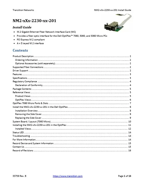
NM2‐xXx‐2230‐xx‐201Install Guide∙M.2 Gigabit Ethernet Fiber Network Interface Card (NIC)∙Provides a fiber optic interface for the Dell OptiPlex™ 7060, 5060, and 3060 Micro PCs∙PCI Express M.2 compliant∙A + E keyed M.2 interfaceContentsProduct Description (2)Ordering Information (2)Optional Accessories (sold separately) (2)Supported Fiber Connections (2)Driver Support (2)Features (3)Specifications (3)Regulatory Compliance (4)Declaration of Conformity (4)Package Contents (5)Reference Views (5)Product Views (5)OptiPlex Views (6)OptiPlex 7060 Micro Ports & Slots (7)Install the NM2‐xXx‐2230‐xx‐201 in the Dell OptiPlex (8)Installation Overview (8)Removing the Side Cover (9)Replacing the Side Cover (9)System Board / Layout (7060 Micro) (10)Installing the NM2‐xXx‐2230‐xx‐201 in the OptiPlex (11)Installed Views (12)Status LED (14)Troubleshooting (14)For More Information (14)Record Device and System Information (15)Contact Us (15)Record of Revisions (16)Product DescriptionTransition Networks NM2‐xXx‐2230‐xx‐201 M.2 Gigabit Ethernet or Fast Ethernet Fiber Network Interface Cards (NICs) provide a fiber optic interface for the Dell OptiPlex™ 7060, 5060, and 3060 Micro PCs. The NM2‐xXx‐2230‐xx‐201 consists of an M.2 NIC that installs into the OptiPlex PC’s M.2 “E key” interface, a fiber optic adapter that installs into the OptiPlex Micro PC’s Option port, and a 20‐pin Flat Flex Cable (FFC) that connects the NIC to the fiber adapter. The NICs are electro‐mechanically designed to be compatible (fit, form, function) with the Dell OptiPlex 7060 Thin Client PC through the use of its M.2 (E Key) slot.M.2 is known as the “next generation form factor” and is a specification for internally mounted computer expansion cards and associated connectors. Desktop PCs are being replaced by smaller computing devices (such as Thin Clients, Micro PCs, Ultrabooks, and Tablets) which typically have internal M.2 interfaces but do not have PCI or PCIe slots. Many users still need fiber Ethernet access, and without the external PCIe slot, there is no standard fiber interface on these devices.See the Dell OptiPlex manual for important notes, cautions, and warnings. Read the section “Before working inside your computer” before proceeding.Ordering InformationSKU DescriptionNM2‐GXE‐2230‐LC‐201 M.2 Gigabit Ethernet Fiber NIC (1000BASE‐SX, 850nm, MM, LC) (fixed optic). 1000Base‐SX 850nm multimode (LC) [62.5/125 μm fiber: 220 m/722 ft.] [50/125 μm fiber: 550 m/1804 ft.] Link Budget: 8.0 dBNM2‐GXE‐2230‐SFP‐201 M.2 Gigabit Ethernet Fiber NIC (1000Base‐X Open SFP Slot)NM2‐FXS‐2230‐SFP‐201 M.2 Fast Ethernet Fiber NIC. M.2 NIC, 100Base‐FX. M.2 NIC; 100Base‐FX to SGMII SFP media converter (included)Optional Accessories (sold separately)SFP Modules: Transition Networks offers a full line of small form factor pluggable (SFP) transceivers. See Transition Networks Optical Devices webpage for relevant SFP modules. See the related SFP manual for cautions and warnings.Supported Fiber Connections∙1000BASE‐SX, 850nm, MM, LC (fixed optic)∙1000BASE‐X, SFP Slot∙100BASE‐SGMII, SFP SlotDriver SupportWindows 10, 8.1, 8, and 7 (32 and 64 bit); LinuxFeatures∙IEEE 802.3‐2012 compliant∙PCI Express M.2 compliant (3.3V) ∙Full Duplex∙IPv6 Capable ∙A + E keyed M.2 interface∙Supports UEFI∙Jumbo frame support 9014 bytes ∙PXE Boot supportSpecifications•Standards: IEEE 802.3‐2012•Bus Slot: M.2 ‐ ‘2230‐D4‐A‐E’•Data Rate: 1000 Mbps (full duplex only)•Max Frame Size: 9014 bytes•Status LEDs: LINK/ACT ON = Link, Flashing = Activity•Dimensions (M.2 NIC) 2230‐D4‐A‐Eo Width: 0.87” [22 mm]o Depth: 1.18” [30 mm]o Height: 0.12” [3.08 mm]•Dimensions (Fiber Interface) Width: 1.65” [42 mm]o Depth: 2.05” [52 mm]o Height: 0.51” [13 mm]•Dimensions (FFC Cable) Length: 2.99” [76 mm]•Power Consumption (LC): 250mA @ 3.3V (0.8 Watts typical)•Power Consumption (SFP): 120mA @ 3.3V (0.4 Watts typical without SFP module) •Power Source M.2 interface connector: 3.3V (Refer to table 41 of M.2 Specification) •Environment:o Operating Temp: 0°C to +45°Co Storage Temp: ‐40°C to 85°Co Humidity: 5% to 95% (non‐condensing)o Altitude: 0 – 10,000 ft.•Weight: 0.1 lbs. [0.05 kg]•Warranty: LifetimeRegulatory ComplianceNote: Modification of NIC voids regulatory agency compliance.Compliance: CE Mark; Emissions: EN55032, FCC Part 15 Class A; Immunity: EN55024Emissions: EN 55032: 2012/AC: 2013; AS/NZS CISPR 32: 2013; VCCI V‐3/2015.04; ICES‐003, Issue 6: 2016; FCC Part 15 Subpart B.Immunity: EN 55024: 2010 (EN 61000‐4‐2: 2009; EN 61000‐4‐3: 2006 + A1: 2008 + A2: 2010; EN 61000‐4‐4: 2004 + AC: 2006 + A1: 2010; EN 61000‐4‐5: 2006; EN 61000‐4‐6: 2009; EN 61000‐4‐8: 2010; EN 61000‐4‐11: 2004).Declaration of ConformityHigh Risk Activities Disclaime r: Components, units, or third‐party products used in the product described herein are NOT fault‐tolerant and are NOT designed, manufactured, or intended for use as on‐line control equipment in the following hazardous environments requiring fail‐safe controls: the operation of Nuclear Facilities, Aircraft Navigation or Aircraft Communication Systems, Air Traffic Control, Life Support, or Weapons Systems ("High Risk Activities"). Transition Networks and its supplier(s) specifically disclaim any expressed or implied warranty of fitness for such High Risk Activities.Package ContentsVerify that you have received the following items. Contact your sales representative if any item is missing. Please save the packaging for possible future use.One TN‐SFP‐GE‐100FX SFP in anti‐static pouch (included with NM2‐FXS‐2230‐SFP‐01 version only).One M.2 NIC PCB attached to FFC Cable in anti‐static pouch.Parts in a 4x6 baggie (1 each): #4 Flat Head Screw, #4 Nylon Washer, #6 Black SEMS Screw.One NM2‐xXx‐2230‐xx‐01 Install Guide (this document).One Product Support Postcard.Reference ViewsProduct ViewsOptiPlex ViewsOptiPlex 7060 Micro Ports & SlotsDell OptiPlex 7060 Micro Front View: 1. Power button and power light. 2. Hard drive activity light.3. Headset/Universal audio jack port.4. Line‐out port.5. USB 3.1 Gen 2 Type‐C port with PowerShare.6. USB 3.1 Gen 1 port with PowerShare.Dell OptiPlex 7060 Micro Back View: 1. External antenna connectors (2) (optional). 2. DisplayPort/VGA/HDMI 2.0b/DP/USB Type‐C alt mode (optional). 3. USB 3.1 Gen 1ports (3). 4. Cable holder. 5. Padlock ring. 6. Network port. 7. USB 3.1 Gen 1 port (supports Smart Power On). 8. Service tag. 9. Kensington security cable slot. 10. DisplayPorts (2). 11. Power connector port.Dell Support for OptiPlex 7060: Diagnostics, Support topics & articles, Drivers & downloads, Manuals & documents, System configuration, and Parts & accessories.Install the NM2‐xXx‐2230‐xx‐201 in the Dell OptiPlexThe NM2‐xXx‐2230‐xx‐201 is designed to install in the Dell OptiPlex™ 7060, 5060, and 3060 Micro PCs.Caution: Only qualified persons should install the NIC. Failure to observe this caution could result in poor performance or damage to the equipment. Before installing the NIC, review the Pre‐Installation Checklist and Safety Precautions below.Caution: Wear a grounding device and observe electrostatic discharge precautions when installing the NIC in a system. Failure to observe this caution could result in damage to the NIC. Before installing the NIC, review the Pre‐Installation Checklist and Safety Precautions below. Before installing the NIC, ensure that system power is OFF, the power cord is unplugged from the power outlet, and that proper electrical grounding procedure has been followed.Warning: High voltage inside the system may present a safety hazard. Make sure that the system power is off before removing the cover. Unplug and disconnect the PC and then wait for 15‐20 seconds before plugging the NIC into the PC. When removing the NIC, unplug the Ethernet cable before removing the PC cover.Note: Refer to the Notes, Cautions, and Warnings in the Dell OptiPlex 7060 Service Manual. See Manuals & documents for details.Class I Laser Compliance: This product has been tested and found to comply with the limits for FDA Class I laser for IEC60825, EN60825, and 21CFR1040 specifications. Warning: Visible and invisible laser radiation when open. DO NOT stare into laser beam or view directly with optical instruments. Failure to observe this warning could result in damage to your eyes or blindness.Installation OverviewBefore installing your NIC, review the preceding sections, and then do the following:1.Verify that your system is using the latest BIOS.2.If you download the driver software, record the path where you saved the downloads.3.If your system is active, shut it down. Do not install the NIC until system power is completely removed.When system shutdown is complete, power OFF and unplug your system.4.Holding the NIC by the edges, remove it from its shipping package and place it on an antistatic surface.5.Check the NIC for signs of damage, particularly on the PCB edge connector. Caution: Never attempt to installa damaged NIC card. If the NIC is damaged, report it to Transition Networks.6.Remove the OptiPlex Side Cover. See Removing the Side Cover below.7.Gently remove the OptiPlex HDD.8.Remove the OptiPlex 15‐Pin DSUB Knockout.9.Insert the M.2 NIC into the OptiPlex Micro PC’s M.2 “E key” interface.10.Insert the fiber optic adapter into the OptiPlex Micro PC’s Option port.11.Replace the OptiPlex HDD.12.Replace the OptiPlex Side Cover.Removing the Side Cover1. Follow the procedure in “Before working inside your computer”.2. To remove the cover:a) Slide the release latch on the back side of the system until it gives a click sound to unlock the side cover [1].b) Slide and lift the side cover from the system [2].Replacing the Side Cover1. Place the cover on the system and slide the cover until it clicks into place [1].2. The release latch automatically locks the side cover to the system [2].System Board / Layout (7060 Micro)Installing the NM2‐xXx‐2230‐xx‐201 in the OptiPlexThe NM2‐xXx‐2230‐xx‐201 consists of a M.2 NIC that installs into the OptiPlex Micro PC’s M.2 “E key” interface, and a fiber optic adapter that installs into the OptiPlex Micro PC’s Option port.1.Remove PC cover.2.Gently remove the HDD Assembly. See the Dell documentation.3.Remove the 15‐Pin DSUB knockout.4.Insert the M.2 NIC into the OptiPlex Micro PC’s M.2 “E key” interface.5.Secure the M.2 NIC Assembly into place using the Securing Screw.6.Insert the fiber optic adapter into the OptiPlex Micro PC’s Option port.7.Attach to PC Case using Black SEMS Screw #6‐32x1/4”, and partially tighten to hold in place as shown below.8.Align #4 Standoff with Top Hole in PC Case.9.Slip #4 Nylon Washer on top of #4 Standoff and insert #4 Screw to secure.10.Tighten using Black SEMS Screw #6‐32x1/4”.11.Lift Locking Lever of FFC Connector on fiber optic adapter.12.Insert end of 20‐Position FFC Cable into fiber optic adapter, with Pins facing down.13.Push Locking Lever Down to Lock. Check that Cable is secure. See figure below for final placement.14.Gently replace the HDD Assembly.15.Replace PC cover.16.Install the SFP in the open SFP slot. On the fixed optic version, connect the fiber adapter/connector.17.Power up the PC.Installed ViewsPXE Boot Loader from PXE boot loader image pre‐loaded: https:///download/19186/Intel‐Ethernet‐Connections‐Boot‐Utility‐Preboot‐Images‐and‐EFI‐Drivers.Intel i210 PROSet Drivers from If your PC does not automatically detect the NM2‐xXx‐2230‐xx‐201 NIC, download and install the standard i210 PROSet drivers from Intel at /content/www/us/en/support/network‐and‐i‐o/ethernet‐products/000005686.html.The Intel® PROSet for Windows* Device Manager is an extension for Windows Device Manager. When you install the Intel PROSet software, tabs are automatically added to the supported Intel adapters in Windows Device Manager.These features allow you to test and configure wired Intel® Ethernet Adapters.The links below apply to the NM2‐GXE‐2230‐xx‐201, the NM2‐FXS‐2230‐SFP‐201, and –D versions. At each link, there is a 32‐bit and a 64‐bit download for each OS.Intel® Network Adapter Driver for Windows* 7.Intel® Network Adapter Driver for Windows* 8.1.Intel® Network Adapter Driver for Windows® 10.The full set of Intel Network Adapter Drivers for download (e.g., for Linux, Windows Server, etc.) is available. Transition Networks Resources page has Drivers (ZIP format) for Windows 10 32bit and 64bit Drivers, Windows 7 32bit and 64bit Drivers, and Windows 8 32bit and 64bit Drivers.Status LEDThe Media Converter has a status LED for checking Link/Activity:Link/ACTivity LED On = Link; Flashing = Activity. Color is amber when 100M.TroubleshootingThis section lists some common problems, their causes, and potential recovery steps.1. Confirm the Pre‐Installation Checklist items on page 8.2. Verify the Hardware Installation Procedure on page 9.3. Check that the cabling is securely attached. See the FOA troubleshooting guide or the SFP manual.4. Check for a mismatch of speed, duplex, protocol, or cable type.5. Make sure the SFP is plugged in to the open SFP slot before you power on the PC. Failure to do so will cause the device to fail, in which case you must shut down and restart the PC.6. Use the troubleshooting procedures in the Dell™ OptiPlex™ User’s Guide.7. Use the troubleshooting procedures on the PXE Boot Loader webpag e as required.8. Use the troubleshooting procedures on the Intel i210 PROSet Drivers webpage as required.9. Verify that the link partner is active and can send/receive traffic; make sure partner settings match; verify that the port is enabled; try connecting to another port or link partner. Check for incompatible or conflicting devices / settings.10. Run Windows Device Manager and scan for changes.11. Check if the PC’s BIOS version is appropriate and update to the latest. See the PC documentation.12. Run the PC diagnostics (e.g., Dell Quick Test or Dell pre‐boot diagnostics).13. Automatically detect and update drivers and software if you are connected to the Internet from the computer that needs updated drivers from /support/network/sb/CS‐031482.htm.14. Record information and contact TN Technical Support. See Recording Model and System Information below.For More InformationTo view the Dell™ OptiPlex™ User’s Guide at the Support Center web page:1.Click Start → Help and Support → Dell User and System Guides → System Guides.2.Click the User’s Guide for your computer.The User’s Guide is also available on the optional Drivers and Utilities media.Technical information in this document is subject to change without notice.See our SFP Products for more SFP information.The Fiber Optic Association, Inc. provides a Technical Bulletin on “Guidelines For Testing And Troubleshooting Fiber Optic Installations” at /tech/guides/TT3.pdf Other FOA Technical Bulletins to be used as references for the design and planning of the network can be downloaded from the FOA Tech Topics website.Record Device and System InformationAfter performing the troubleshooting steps, and before calling or emailing Technical Support, please record as much information as possible in order to help the TN Tech Support Specialist. Record the following information: 1. Product ID: ___________________________ MAC Address: ________________________________________ Serial #: _______________________________ Board Rev: ___________________________________________ LED status: __________________________________________________________________________________ 2. Record the System information: Check your computer documentation for support information.PC make and model: ________________________________________________________________________ Operating System: __________________________________________________________________________ BIOS version: ______________________________________________________________________________ Intel i210 Driver version: _____________________________________________________________________ PC’s Icon Tray indication: _____________________________________________________________________ Connected Device(s): ________________________________________________________________________3. Provide your TN service contract number: _______________________________________________________4. Describe the failure: _________________________________________________________________________ ___________________________________________________________________________________________ ___________________________________________________________________________________________5. Describe any action(s) already taken to resolve the problem: ________________________________________ ___________________________________________________________________________________________ ___________________________________________________________________________________________Contact UsTechnical Support: Technical support is available 24‐hours a dayUS and Canada: 1‐800‐260‐1312International: 00‐1‐952‐941‐7600Main Officetel: +1.952.941.7600 | toll free: 1.800.526.9267 | fax: 952.941.2322******************** | ************************** | ******************************AddressTransition Networks10900 Red Circle DriveMinnetonka, MN 55343, U.S.A.Web: https://Record of RevisionsRev Date NotesA 7/24/18 Initial release for production.B 11/14/18 Incorporate technical and editorial changes.Trademark notice: All trademarks and registered trademarks are the property of their respective owners. Copyright restrictions: © 2018 Transition Networks. All rights reserved. No part of this work may be reproduced or used in any form or by any means ‐ graphic, electronic or mechanical ‐ without written permission from Transition Networks.。

企業資訊安全防護系統程式版本:Ver 4.3文件版本:Ver 1.0參考手冊~第2章~【X-FORT 安裝手冊】Copyright© 2012 FineArt Technology Co., Ltd. All rights reserved.X-FORT 安裝手冊index第 1 章【系統安裝】 (1)1-1X-FORT 伺服端(X-FORT Server)系統需求 (1)1-2X-FORT快速安裝 (2)1-2-1X-FORT伺服端(X-FORT Server) (2)1-2-2X-FORT用戶端(X-FORT Client) (3)1-3重要檔案 (4)1-4X-FORT Server安裝說明 (5)1-4-1設定X-FORT伺服器 (9)1-4-2設定FORT備援伺服器 (16)1-4-3升級FORT伺服器 (17)1-4-4語系選項 (17)1-5X-FORT 用戶端安裝說明 (18)1-6X-FORT用戶端程式補充事項 (23)1-7編輯Agent的更新訊息 (26)1-8用戶端電腦(Client)解除安裝 (28)1-9檔案伺服器防護程式(File Server Agent)安裝 (30)第 2 章【授權】 (32)2-1啟用授權 (32)2-2檢視授權資訊 (34)1-1 X-FORT 伺服端(X-FORT Server)系統需求(1) 作業系統: Windows 2000 以上版本。
(2) JRE(Java Runtime Environment)1.6 以上版本。
1-2 X-FORT快速安裝1-2-1 X-FORT伺服端(X-FORT Server)步驟如下:(1) 將要安裝的電腦加入網域。
(2) 安裝MS SQL Server(建議採用SQL 2005 Service Pack 3以上的版本),做為建立X-FORT 系統專屬資料庫用途,MS SQL Server可與X-FORT伺服端同一台電腦,或者獨立一台。
Teamcenter10.1安装手册Teamcenter10.1安装手册Teamcenter 10.1InstallationWindows Publication Number__2 Jon Clients GuideTeamcenter10.1安装手册Proprietary and restricted rights noticeThis software and related documentation are proprietary to Siemens Product Lifecycle Management Software Inc.2022年Siemens Product Lifecycle Management Software Inc. All Rights Reserved. Siemens and the Siemens logo are registered trademarks of Siemens AG. Teamcenter is a trademark or registered trademark of Siemens Product Lifecycle Management Software Inc. or its subsidiaries in the United States and in other countries. All other trademarks, registered trademarks, or service marks belong to their respective holders.Teamcenter10.1安装手册ContentsProprietary and restricted rightsnotice ............................................................. 2 Getting started with Teamcenter client installation ....................................... 1-1 Introduction to Teamcenter client installationSystem requirements ................................................................. 1-1 Preparing to installTeamcenter ............................................................................................................. Configuring Teamcenterinstallation ............................................................................................... 11-1-6 Starting Teamcenter installation .................................................................................. 1-7 Teamcenter Environment Managerinterface ......................................................................................... 1-7 Basic concepts about Teamcenterinstallation ................................................................... ........................................................ .......... 11-7-8 Installing the richclient ............................................................................. 2-1 Before you startInstall a four-tier richclient ....................................................................................................................... Install a two-tier rich clientAlternate rich clientconfigurations . ................................................................................................... .............. ................................................................................... 22-12-1 -6 Configure rich clientfeatures ............................................................................................ .................................... .............................................. 2-102-11 Creating a customdistribution ......................................................................... 3-1 Overview of custom distributionsCreate a silentdistribution ........................................................................................ 3Create a compactdistribution ................................................................................................... ...................... ........................................................................ 3-13-2 -5 Installing Microsoft Office interfaces .............................................................. 4-1 Installing Microsoft Office interfacesInstalling Teamcenter Client for MicrosoftOffice .................................................................................. 4-1 Installing Teamcenter Extensions for Microsoft Office ............................................................ Install Teamcenter Plug-in for Microsoft ProjectPatching Client forOffice ........................................................... ................................................ 4-124-2 Patching Extensions for Office.................................................................................................... 4-16 ........................................................................................... 4-16 4-18 Installing TCCS ....................................................................................................... 5-1 What is TCCS?Preparing to installTCCS ......................................................................................................................... 5-1 Enable TCCS usingTEM ..................................................................................................... 5-2 Install TCCS using the stand-alone installation wizard....................................................................................................... ................................................. 55-3-6Troubleshooting . . . . . . . . . . . . . . . . . . . . . . . . . . . . . . . . . . . . . . . . . . . A-1 Enabling multiple client sessions . . . . . . . . . . . . . . . . . . . . . . . . . . . . . . B-1 Overview of multiple client sessions . . . . . . . . . . . . . . . . . . . . . . . . . . . . . . . Installing support services for multiple client sessions . . . . . . . . . . . . . . . . . . B-1 Uninstalling multiple client supportservices . . . . . . . . . . . . . . . . . . . . . . . . . B-2B-1Teamcenter10.1安装手册ContentsUninstalling Teamcenter . . . . . . . . . . . . . . . . . . . . . . . . . . . . . . . . . . . . . C-1 Uninstall the rich client . . . . . . . . . . . . . . . . . . . . . . . . . . . . . . . . . . . . . . . C-1 Uninstall Microsoft Office interfaces . . . . . . . . . . . . . . . . . . . . . . . . . . . . . . . C-2 Uninstall TCCS . . . . . . . . . . . . . . . . . . . . . . . . . . . . . . . . . . . . . . . . . . . . . C-4 Uninstall Engineering Process Management rich client . . . . . . . . . . . . . . . . . C-4 Glossary . . . . . . . . . . . . . . . . . . . . . . . . . . . . . . . . . . . . . . . . . . . . . . . . . . D-1 Index . . . . . . . . . . . . . . . . . . . . . . . . . . . . . . . . . . . . . . . . . . . . . . . . . Index-1FiguresTeamcenter EnvironmentManager ........................................................................ 1-7 Two-tier architecture .................................................................................................. 1-9 Four-tier architecture .............................................................................................. 1-11 Sample silent installation configuration file .........................................................3-5Platform support for Teamcenter servers andclients .......................................... 1-2 Required hard disk space for Teamcenter configurations .................................. 1-4Teamcenter10.1安装手册Chapter1Getting started with client installationTeamcenter Introduction to Teamcenter clientinstallation ................................................................. 1-1 System requirementsWhere to find systemrequirements ............................................................................................................. 1-1 PlatformsSystemhardware ........................................................................................................................... .. ........................................................................... 11-1 Web browserJava Runtime Environment ...................................................................................................................... . ............................................................................................................ 1-11-3 -4 Softwareintegrations ...................................................................................................... .................. ........................................................................ 11-4-5 Preparing to install Teamcenter .............................................................................................. 1-6 Configuring Teamcenterinstallation .................................................................................. 1-7 Starting Teamcenter installation ........................................................................................ 1-7 Teamcenter Environment Managerinterface ................................................................... 1-7 Basic concepts about Teamcenter installationTeamcenterclients .................................................................. 1-8Richclient ................................................................................................................... .................. ......................................................................................... 1-8Teamcenter network architecturesThinclient .................................................................................................................. 11-8-8 Two-tierarchitecture ............................................................................................... ......................... ...................................................... 11-8File Management System (FMS)Four-tierarchitecture ............................................................................................... 1-8-9 Selecting and configuringfeatures ............................................................................... Basic tasks in Teamcenter installation............................................................................ 1-121-12 Installing Teamcenter clientsInstalling clientfeatures ...................................................................................... .......................................... .................................... .................................................................... 1-13 1-13 1-13Teamcenter10.1安装手册Teamcenter10.1安装手册Introduction to Teamcenter client installationThis guide describes how to install Teamcenter 10.1 on Microsoft Windows clients. This includes installation of Teamcenter two-tier rich clients using Teamcenter Environment Manager and four-tier rich clients using the Over-the-Web Installer. This guide assumes you have a thorough working knowledge of your operating system and general knowledge of Teamcenter use.System requirementsWhere to find system requirementsFor information about versions of operating systems, third-party software, Teamcenter software, and system hardware certified for your platform, see the Siemens PLM Software Certification Database: / certification/teamcenter.shtmlNoteSome software requirements differ for non-English locales. When viewing the certification database, make sure you note any exceptions for your locale.PlatformsDetermine from the following table which Teamcenter 10.1 servers and clients are supported on your operating system. Bullet characters ( )denote supported servers and clients.Teamcenter10.1安装手册Chapter 1Getting started with Teamcenter client installationPlatform support for Teamcenter servers and clientsOperating System Microsoft Windows (desktop platforms)2 Microsoft Windows (server platforms)3 Sun SolarisHewlett-Packard HP-UX4 IBM AIX SUSE Linux Red Hat Linux5Apple Macintosh Mac OSCorporate Web server tierBusinessModelerRich Thin IDETCCS1 client client clientNotes about platform supportGeneral notesFor information about versions of operating systems certified for Teamcenter10.1, see the Siemens PLM Software Certification Database. For information about installing Teamcenter on Windows servers, see the Installation on Windows Servers Guide. For information about installing Teamcenter on Linux clients, see theInstallation on Linux Clients Guide. For information about installing Teamcenter on Macintosh clients, see theInstallation on Macintosh Clients Guide. If your Teamcenter database server is IBM DB2, all Teamcenter servers andtwo-tier rich clients in your network must run operating systems supported for Teamcenter with IBM DB2. IBM DB2 databases are supported only with Teamcenter servers running on Microsoft Windows, IBM AIX, or SUSE Linux platforms. Microsoft WindowsMake sure the C:\Temp directory exists, and grant full access permissionsto this directory for all users.1. Teamcenter client communication system (TCCS) is installed with the rich client. This column refers to the stand-alone TCCS application.2. Microsoft Windows desktop platforms include Windows XP and Windows 7.3. Microsoft Windows server platforms include Windows Server 2022年.4. Itanium platforms only. PA-RISC hardware is not supported.5. Only 64-bit Red Hat Linux is supported.Teamcenter10.1安装手册Getting started with Teamcenter client installationOn Windows Server and Windows 7, disable Windows User Account Control(UAC) before you install Teamcenter. This option is available in theControl Panel→User Accounts dialog box.Windows UAC can interfere with Teamcenter installation programs. Siemens PLM Software recommends turning off UAC for administrative users only.For more information, see Microsoft Windows documentation.Disable the Windows TCP scaling feature. Open a command prompt andenter the following command:netsh interface tcp set global autotuninglevel=disabledSiemens PLM Software recommends setting this parameter before installing Teamcenter because most client network infrastructures use one or more switches or routers. By default, Windows enables TCP window scaling, but some routers do not support this feature. This can cause installation failures that are difficult to diagnose and correct.For more information, see Microsoft Windows documentation.Teamcenter applications are provided in 32-bit and 64-bit versions. Use theappropriate Teamcenter software distribution image for your platform. If you use a nonnative language operating system version of Windows, youmust install and enable the Multilingual User Interface (MUI) pack to ensure the language font is displayed properly.1. Download and install the MUI pack for Windows from Microsoft.2. Open the Regional and Language Options dialog box in the WindowsControl Panel. 3. In the Languages tab, set the required language for the menus anddialogs. 4. In the Advanced tab and the Regional Options tab, set the requiredlanguage.System hardwareMake sure your Teamcenter host has the required amount of disk space available. Required hard disk space for Teamcenter configurations shows the required disk space for the following common Teamcenter configurations: Corporate serverThe corporate server contains the features included in the Corporate Server solution in Teamcenter Environment Manager (TEM). Additional features may require additional disk space.For more information, see the appropriate server installation guide (for Windows or UNIX/Linux). Two-tier rich clientTeamcenter10.1安装手册Chapter 1 Getting started with Teamcenter client installationThe two-tier rich client contains the features included in the Rich Client 2-tier solution in Teamcenter Environment Manager (TEM).Additional features may require additional disk space.For more information, see Install a two-tier rich client.Web tierThe Web tier includes the Web Application Manager, a distribution server, and a distribution server instance that contains the Over-the-Web installer and Rich Client 4-tier solutions. Additional solutions may require additional disk space. For more information, see the appropriate server installation guide (for Windows or UNIX/Linux).Required hard disk space for Teamcenter configurationsPlatformHewlett-Packard HP-UX6 IBM AIX SUSE Linux Red Hat Linux Sun Solaris Microsoft WindowsCorporate server 3.0 GB 2.0 GB 2.0 GB 2.0 GB 2.5 GB 1.5 GBTwo-tier rich client Not supported Not supported 300 MB 300 MB Not supported 450 MBWeb tier 3 GB 3 GB 3 GB 3 GB 3 GB 4.5 GBWeb browserThe Teamcenter thin client and Over-the-Web Installer7 require a Web browser. Teamcenter 10.1 supports the following Web browsers: Windows systems: Microsoft Internet Explorer and Mozilla Firefox Linux systems: Mozilla Firefox Macintosh systems: Apple Safari For information about versions supported, see the Siemens PLMSoftware Certification Database.Java Runtime EnvironmentTeamcenter Environment Manager (TEM) requires a supported Java Runtime Environment (JRE). You must download and install the required JRE before you install Teamcenter.For information about required versions of the JRE for Teamcenter, see the Siemens PLM Software certification database:6. Itanium platforms only. PA-RISC hardware is not supported.7. The Over-the-Web Installer installs the four-tier Teamcenter rich client and Teamcenter Microsoft Office interfaces.Teamcenter10.1安装手册Getting started with Teamcenter client installation/ certification/teamcenter.shtmlTEM verifies the required version of Java is available on the host. If the required version is not present, TEM does not launch.Before you launch TEM to install Teamcenter, specify the location of the JRE by one of the following methods:Set the appropriate environment variable on your host:o32-bit JavaSet the JRE_HOME environment variable to the location of the 32-bit Java JRE. o64-bit JavaSet the JRE64_HOME environment variable to the location of the 64-bit Java JRE.NoteYou must use the appropriate Teamcenter software distribution image (32-bit or 64-bit) for the JRE you use.Use the -jre argument to specify the JRE location when you launch TEM from acommand prompt:tem ―jre JRE-pathFor example:tem Cjre c:\apps\jre1.7TEM stores the JRE location during Teamcenter installation. After installation is complete, TEM no longer requires the JRE_HOME orJRE64_HOME environment variable or the -jre argument.Software integrationsIf you use Teamcenter 10.1 integrations to other Siemens PLM Software products or third-party software, install those products before you install Teamcenter 10.1. Some Siemens PLM Software products require separate licenses from your Siemens PLM Software representative. Siemens PLM Software products are licensed using the Siemens PLM Software Common Licensing Server.For more information about the Common Licensing Server, see the appropriate server installation guide (for Windows or UNIX/Linux).If you use any of the following integrations with the rich client, make sure you install these applications in locations specified by the Teamcenter administrator. Teamcenter Integration for NX or NX Integration Obtain the NX software distribution image and install a supported version of NX on your workstation. You must install the optional Teamcenter Integration for NX executables.For installation information, see the installation guide distributed with NX. Lifecycle VisualizationTeamcenter10.1安装手册Chapter 1 Getting started with Teamcenter client installationObtain the Lifecycle Visualization software distribution image and install a supported version of Lifecycle Visualization on your workstation.For installation information, see the installation guide distributed with Lifecycle Visualization.SCM Integration C ClearCaseObtain the IBM Rational ClearCase client distribution image and install a supported version on your workstation.NoteTeamcenter Microsoft Office interfaces require additional software. For more information, see Installing Microsoft Office interfaces.Preparing to install TeamcenterTo enable Teamcenter Environment Manager (TEM), make sure you complete the following:Locate the Teamcenter software and documentation distribution images andmake sure they are accessible to your host. Specify the path to the required Java Runtime Environment (JRE) by settingthe appropriate environment variable on your host:o32-bit JavaSet the JRE_HOME environment variable to the location of the 32-bit Java JRE.o 64-bit JavaSet the JRE64_HOME environment variable to the location of the 64-bit Java JRE.NoteYou must use the appropriate Teamcenter software distribution image (32-bit or 64-bit) for the JRE you use.Alternatively, you can specify the JRE path from the command line using the -jre argument when you launch TEM:tem ―jre JRE-pathFor example:tem Cjre c:\apps\jre1.7For information about required versions of the JRE for Teamcenter, see the Siemens PLM Software certification database:/ certification/teamcenter.shtmlTeamcenter10.1安装手册Getting started with Teamcenter client installationConfiguring Teamcenter installationIf your Teamcenter administrator configured the rich client to include Teamcenter lifecycle visualization, ensure you have administrator privileges on your workstation.Starting Teamcenter installationTo begin installing Teamcenter installation, launch the appropriate Teamcenter installation tool:Teamcenter Environment ManagerTo install a Teamcenter rich client, launch Teamcenter Environment Manager using the tem.bat command from the Teamcenter software distribution image. Over-the-Web InstallerTo install a Teamcenter four-tier rich client, open the URL to theOver-the-Web Installer provided by your Teamcenter administrator.Teamcenter Environment Manager interfaceTeamcenter Environment Manager is a tool that installs Teamcenter two-tier and four-tier rich clients.Teamcenter Environment ManagerTeamcenter10.1安装手册Chapter 1 Getting started with Teamcenter client installationTeamcenter Environment Manager also performs maintenance operations, such as upgrading servers, applying maintenance packs, and installing patches. You launch Teamcenter Environment Manager using the tem.bat command.Basic concepts about Teamcenter installationTeamcenter clientsTeamcenter provides clients suited to various uses and network configurations. These clients include the rich client, the thin client, and specialized clients such as Teamcenter Client for Microsoft Office and Teamcenter Extensions for Microsoft Office. Rich clientThe rich client is a platform-independent client implementation (Java application) for users who interact with Teamcenter frequently. It is extendable and able to run both Teamcenter and customer-written applications. Customers can also extend the standard user interface.The rich client application is deployed on each user workstation using Teamcenter Environment Manager or the Over-the-Web Installer, depending on which Teamcenter network architecture you use. The rich client is supported in both architectural models described in Two-tier architecture and Four-tier architecture. Thin clientThe thin client provides access to Teamcenter through a standard commercial Web browser, such as Microsoft Internet Explorer or Mozilla Firefox. The user interface provides a streamlined browser-based view of product information stored in a Teamcenter database.The thin client is supported only in the four-tier architectural model described in Four-tier architecture.Teamcenter network architecturesTeamcenter provides two architecture models for deployment: two-tier and four-tier. Two-tier architectureThe two-tier architectural model comprises the following tiers: Client tierThe client tier comprises the Teamcenter rich clients.In a deployment of the two-tier architecture, the Teamcenter server runs on the client workstation.Teamcenter10.1安装手册Getting started with Teamcenter client installationNoteThe two-tier rich client is installed only through TEM. Over-the-Web installation is supported only for the four-tier rich client.Some Teamcenter client features, such as Teamcenter Integration for NX, Lifecycle Visualization, and Teamcenter Client for Microsoft Office, require the Web tier, a component of the four-tier architecture. To enablethese features for a two-tier rich client, you can connect the two-tier rich client to a deployment of the Web tier. For information about functionality you can add to a rich client and which add-ons require the Web tier, see the appropriate server installation guide (for Windows or UNIX/Linux).Resource tierThe resource tier comprises a database server, database, volumes, and file servers.Two-tier architectureIn the two-tier model, you deploy the Teamcenter rich client, which includes the local server, and the optional applications that integrate with the rich client on the client workstation. Typically, the database server, volumes, and file servers are installed on one or more separate hosts.Teamcenter File Management System (FMS) manages the rich client access to volumes:The FMS server cache (FSC) process run on the server hosting the volume.The FMS client cache (FCC) process runs on the rich client host.For more information about FMS and two-tier rich client architecture, see the appropriate Teamcenter server installation guide (for Windows or UNIX/Linux). Four-tier architectureThe four-tier architecture model comprises the following tiers:Teamcenter10.1安装手册Chapter 1 Getting started with Teamcenter client installationClient tierThe client tier comprises the Teamcenter rich client, thin client, and other clients such as Teamcenter Client for Microsoft Office.NoteThe rich client can be deployed with additional functionality, such as Lifecycle Visualization, Teamcenter Client for Microsoft Office, and Teamcenter Integration for NX or NX Integration 4.0.1. (Teamcenter Integration for NX/NX Integration 3 is not supported.)J2EE Web tierThe J2EE Web tier is a Java application that runs in a Java 2 Enterprise Edition (J2EE) application server, such as Oracle WebLogic, and is responsible forcommunication between the client tier and enterprise tier. For information about supported application servers, see the Siemens PLM Software Certification Database:/ certification/teamcenter.shtmlEnterprise tierThe enterprise tier comprises a configurable pool of Teamcenter C++ server processes and a server manager. The enterprise tier retrieves data from and stores data in the database.A server manager manages a pool of Teamcenter server processes.You must install a server manager whenever you deploy the Web tier.NoteTeamcenter provides server managers based on the J2EE and the Microsoft .NET platforms. Install the appropriate server manager for the Web tier you use.Resource tierThe resource tier comprises a database server, database, volumes, and file servers.Teamcenter10.1安装手册Getting started with Teamcenter client installationFour-tier architectureYou can design deployments that host the Web tier, resource tier, and enterprisetiers on the same computer or on separate computers: Smaller sites can run the pool of servers and the server manager on the samehost as the Web tier.Larger sites can distribute the pool of server processes across multiple hostsand optionally include an HTTP server to serve static files or multiple HTTPservers to support load balancing.For a multihost configuration, the server pool consists of multiple subpools, oneor more for each host. Each subpool is managed by one server manager process. The Web tier balances the load across the serverpools.Teamcenter10.1安装手册Chapter 1 Getting started with Teamcenter client installationThe Teamcenter J2EE based server manager and Web tier application both employ the JBoss cache, a tree-structured cache, to provide replication and transaction context. You must configure the JBoss cache (called TreeCache in Teamcenter) in both the J2EE based server manager and the Web tier application.8To ensure communication between the Web tier and the server manager, you must coordinate the values you specify for each component. For some values, you must provide the identical value when configuring the Web tier application.For more information about four-tier rich client architecture, see the appropriate Teamcenter server installation manual (for Windows orUNIX/Linux). A minimum of one server manager for each Web tier deployment.A separate TreeCache cluster for each environment.To configure a separate TreeCache cluster, Siemens PLM Software recommends configuring a different port (multicast) or set of ports (TCP) for each cluster.File Management System (FMS)File Management System (FMS) is a file storage, caching, distribution,。
For VENTEX ESI-E /-D and -C with housing material in mild steel and stainless steel/ Function diagram VENTEX ESI-E & VENTEX ESI-D/ Function diagram VENTEX ESI-C/ Certified forZone inside:Certificate CE 0081Ex II 1GD IIB / Zone 0, 1, 2, 20, 21, 22Zone outside:The outside zone is depending on the execution of the mounted parts (e.g. Switch)./ Description/ Technical dataThe data for air speed 20m/s and 25m/s applies to optimal conditions. See the description of the optimal conditions on page two.Maximum air speed in the opposite direction than the explosion direction for VENTEX ESI-E and VENTEX ESI-C = 35m/sOrganic dust up to K-Value 300Organic dust K-Value 301 to 400Gas, Gas group IIBHybride mixturesMetallic dust (Aluminium)334345max. m12121212121212121212121212Installation distancemin. m3333333max. K-Value bar x m x s -1300300300300300300300300300300300300300Basic positionIn operationIn case of an explosionBasic positionIn operationIn case of an explosionsingle acting VENTEX ESI-E VENTEX ESI-EO VENTEX ESI-EUdouble actingVENTEX ESI-D VENTEX ESI-DV/ In case of an explosion, the pressure wave pushes the closing device (without externel energy supply) against the valve gasket./ The valve is locked in this closed state, preventing the spread of flames and pressure waves.FunctionInstallation positionhorizontalVerticalExplosion from top Explosion from bottom check valve with locking fuinctionVENTEX ESI-CVENTEX ESI-CO VENTEX ESI-CUNominal diameterDN100DN150DN200DN300DN400DN500DN600Type 6666666Certificate number FSA (year) ATEX (no.)12/1622X 12/1623X 12/1624X 12/1625X 12/1626X 12/1627X14/1646XExplosion pressure at 20°C min. bar(g)0.050.050.050.05202520max. air speedm/s 20252025max. bar(abs)14141414140.050.050.050.050.050.12141414141420252520250.050.061414400400400400400max. K-Value bar x m x s -14004004004004004004003443---Installation distancemin. m3333333663---max. m55555555Installation distancemin. m333333100max. K-Value bar x m x s -1100100100100100100100100100100100max. m 88888883334348888840040043---max. m 555533bar x m x s -14004004004004004003---566Installation distancemin. m 333400400400400max. K-Value5554504504504503334Installation distancemin. m 33 3.1 3.144450450------300300max. m 3.5 3.5max. K-Valuebar x m x s -1400400 5.45.1 5.155544------VENTEX ESI-C only as pressure barrier (no flame barrier)min. m1111111250.21340055.21006.1513.858 (100) 430(3.85) 3.85(8) 5.23004.85111115.2 5.25------ 5.4/ Requirements on the installation situationRequirements and notes Change of the nominal diameter (DN) in front of the valve in explosion direction Influences the explosion pressure. (Attention: take account of burst strenght/resistance and minimum required explosion pressure of the valve). If the nominal diameters of the pipe and the valve aredifferent the cone has to be mounted directly in front of the valve. Recommended cone <16°.Installation situation Providing of the functionality in case of an explosion (the valve must close)Important: The requirements in case of an explosion have priority compared to the requirements for normal operation.Operating temperature > +90°CReduces the max. allowed explosion pressure. See details in the technical data sheet of the valve.Min./max. installation distance must be measured from the wall of the vessel to the flange of the VENTEX® valve.Pipe elbow in front of the valve in explosion directionDoes not influence the minimum needed explosion pressure.The maximum allowed deviation between the nominal diameters (DN) is double cross-section surface.Max./min. allowed change of the nominal diameter (DN) in explosion direction14121228342456670784971106141212283354424100200300400500600700800900100150200300400500600m mNennweite / Nominal sizeDN1 (max.)DN1 (min.)Requirements and notesRequirements and notes No dust deposits are allowed which might prevent the tight closing of the valve. Danger exists due to thecombination of dust and condensate.Limit values for operation (obligatory):/ air speed > 12 m/s / particle size < 0.5 mm/ dust concentration < 50 g/m 3/ dry air and no condensate/ VENTEX ESI-C allows no dust loadingInstallation situation Providing of the functionality in case of an explosion (the valve must close)Important: The requirements in case of an explosion have priority compared to the requirements for normal operation.Installation situation The max. volume flow contained in the technical data sheet must be observed and can only beachieved under optimum conditions.Maximal allowed volume/air speed VENTEX ESI-D / VENTEX ESI-E (flow and explosion direction are identical)VENTEX ESI-D / VENTEX ESI-E (flow and explosion direction are identical)Pipe in front of the valve in process direction In front of the valve in flow and explosion direction, the length of the straight pipe has to be at leasttenfold the nominal diameter the valve (10 x DN).Elbow in front of the valve in operation/process direction The mean arc radius (r) of the elbow has to have at least the triple size of the nominal diameter (3 x DN) of the valve. Smaller arc radiuses reduce the maximum achievable air speed.Change of the nominal diameter (DN) after the valve in explosion direction After the valve, the length of the pipe (min. PN1) has to be at least fivefold of the nominal diameter of the valve (5 x DN).Allowed dust loadingProviding of functionality in normal operation (valve must not close)VENTEX ESI-C / VENTEX ESI-E (Flow and explosion direction against each other)/ DimensionsDimensions of flanges according DIN 1092-1Dimensions of flanges according ANSI #150WeightRICO Sicherheitstechnik AG reserves the right to make technical changes or modify the contents of this document without prior notice.Nominal diameterDN100DN150DN200DN300DN400DN500DN60094013001420ø Middle flange DM 215315417550682Length L E:350, D:400500610780814929ø Connecting flange DF 220285340445565670780Thickness flange S 22242426323636515620725Quantity x ø Hole n x d 8 x 188 x 228 x 2212 x 2216 x 26Circle-øTK 18024029540020 x 2620 x 30Length L E:350, D:40050061078094013001420ø Middle flange DM 215315417550682814929597698.5812.8Thickness flange S 2025.4242632ø Connecting flange DF 228.62803434833636Circle-øTK 190.5241.3298.4431.8540635749.3Quantity x ø Hole n x d 8 x 198 x 228 x 2212 x 2216 x 28.620 x 3220 x 34.9241354133213305Weight (gross) ca. kg 34436194153Weight (net)ca. kg 30355384。
Sun SPARC Enterprise®T5120 和 T5220 服务器管理指南Sun Microsystems, Inc.文件号码820-2884-122009 年 7 月,修订版 01请将有关本文档的意见和建议提交至:/hwdocs/feedback请回收版权所有 © 2009 Sun Microsystems, Inc., 4150 Network Circle, Santa Clara, California 95054, U.S.A. 保留所有权利。
FUJITSU LIMITED 对本文档的某些部分提供了技术支持并进行了审校。
对于本文档中介绍的产品和技术,Sun Microsystems, Inc. 和 Fujitsu Limited 分别拥有相关的知识产权,此类产品、技术及本文档受版权法、专利法与其他知识产权法和国际公约的保护。
Sun Microsystems, Inc. 和 Fujitsu Limited 在此类产品、技术及本文档中拥有的知识产权包括(但不限于)在 /patents 中列出的一项或多项美国专利,以及在美国或其他国家/地区申请的一项或多项其他专利或待批专利。
本文档及其相关产品和技术的使用、复制、分发和反编译均受许可证限制。
未经 Fujitsu Limited 和 Sun Microsystems, Inc. 及其适用许可方(如果有)的事先书面许可,不得以任何形式、任何手段复制此类产品或技术或本文档的任何部分。
提供本文档并不意味着赋予您对相关产品或技术的任何明示或默示的权利或许可,而且本文档不包含也不表示 Fujitsu Limited 或 Sun Microsystems, Inc. 或各自分支机构作出的任何种类的任何承诺。
本文档以及其中介绍的产品和技术可能包含已从 Fujitsu Limited 和/或 Sun Microsystems, Inc. 供应商处获得版权和/或使用许可的第三方知识产权,包括软件和字体技术。
Micro FocusThe Lawn22-30 Old Bath RoadNewbury, Berkshire RG14 1QNUK© Copyright 2019 Micro Focus or one of its affiliates.MICRO FOCUS, the Micro Focus logo and Connect are trademarks or registered trademarksof Micro Focus or one of its affiliates.All other marks are the property of their respective owners.2019-01-31iiContentsAbout Micro Focus Connect (4)Micro Focus Connect System Requirements (5)Installing Micro Focus Connect (6)Upgrading from APTS or other Micro Focus Connect Releases (7)Starting the Connect UI (8)Backing up Micro Focus Connect data (9)Licensing (10)Contents | 3About Micro Focus ConnectMicro Focus Connect is a tool used to synchronize item and relationship data between various Micro Focussoftware change and configuration management systems and other repositories or clients. Once data issynchronized into the system, all of the change management capabilities of the system, includingversioning, branching, tracing, labeling, and reporting, are available on that data.Note: SCM (Git, SVN or StarT eam SCM) is not supported in 3.1. See the Known Issues section forfurther details.4 | About Micro Focus ConnectMicro Focus Connect SystemRequirementsThis section lists system requirements needed to run Micro Focus Connect.Web Browsers•Google Chrome 35+•Mozilla Firefox 30+•Internet Explorer 10+Operating Systems•Microsoft Windows Server 2016•Microsoft Windows Server 2012 R2•Microsoft Windows Server 2012•Microsoft Windows Server 2008 (64-bit)Note:Micro Focus Connect only provides a 64-bit installation.HardwareRecommended64-bit, quad-core systems with 8-16GB of memory.Micro Focus Connect System Requirements | 5Installing Micro Focus ConnectPerform the following steps to install Micro Focus Connect:1.Double click the installer named MicroFocusConnect-<version-OS_Info>.exe. TheIntroduction page opens.2.Click Next. The License Agreement page opens.3.Choose I accept the terms of the License Agreement and click Next. The Choose Install Folderpage opens.4.Accept the default or click Choose to select a new location. Click Next. The Choose Shortcut Folderpage opens.5.Select where you want the Shortcut Folder and click Next. Micro Focus Connect will be configured foryour system and the Pre-Installation Summary page opens.6.Click Install. The Installing Connect page opens and the installation process starts. When theinstallation is done, the Install Complete page opens.7.Click Done. The installation is complete. The service Micro Focus Connect Web Server isinstalled and running.6 | Installing Micro Focus ConnectUpgrading from APTS or other Micro Focus Connect ReleasesBefore upgrading Micro Focus Connect, you should first stop any connections that are running in yourexisting installation. The updated version of Micro Focus Connect uses a database for trackingrelationships of items and once information has been fully migrated to the new system, any changes backto prior configurations may cause duplication of data.Note: For the stand-alone installation, the Connect.xml file must be in-place before starting theservice. The migration occurs only once. If a Connect.xml file is not there then the default ismigrated.Users upgrading Micro Focus Connect from a prior release should install the new product on a newsystem. Once installed they should stop the system service Micro Focus Connect Web Server), remove theAppData/data/db directory and replace the AppData/data/Connect.xml file with theirConnect.xml file from their prior release, and restart the system service.Upgrading from APTS or other Micro Focus Connect Releases | 7Starting the Connect UITo run the Micro Focus Connect UI:1.In a supported browser, type in: http://<machine-name>:8081/ConnectWeb/. The Micro FocusConnect Sign In page opens.2.Enter Administrator and Administrator for the Username and Password.3.Leave the DefaultAuthenticator selection for the initial installation.4.Click Sign In. The Micro Focus Connect UI opens.For more information on using the UI, refer to Using Micro Focus Connect .8 | Starting the Connect UIBacking up Micro Focus Connect data With the additional support of Micro Focus Products as Master products in configurations, Micro FocusConnect now stores necessary field relationship information and configuration information in a database.The simplest mechanism for backing up the database is to stop the Microsoft Windows service, backup theAppData/data/db directory and its contents (optionally also backup the AppData/data/Connect.xmlfile) as you would backup other critical data.Backing up Micro Focus Connect data | 9LicensingMicro Focus Connect will run in evaluation mode for 60 days. At the end of this period, contact Micro Focusfor a license file, BCLicense.bin. When you receive the license file, place it in the C:\Program Files\Micro Focus\Connect\AppData\data directory.10 | LicensingIndexAabout 4Bback up 9I installation 6Llicensing 10Sstarting the Connect UI 8system requirements 5Uupgrading 7Index | 11。
Guide to Planning and Installing Your BizfonSystemTABLE OF CONTENTSCUSTOMER SITE SURVEY (1)CUSTOMER INFORMATION (1)PART 1 – EMPLOYEE AND LOCATION INFORMATION (2)PART 2 – PHONE SYSTE M (3)V OICE S ERVICE D ELIVERY (3)C URRENT P HONE S YSTEM (4)B IZFON S YSTEM C ONFIGURATION (5)P HONE S YSTEM F EATURES (7)B IZFON P HONE D EFINITIONS (9)B IZ T OUCH™ IP2 C ONFIGURATION (11)PART 3 – IT ENVIRONM ENT (16)PART 4 – UNIFIED MESSAGING (19)PART 5 – PHYSICAL INFRASTRUCTURE (20)PART 6 – DOCUMENTATION (21)50 Stiles Road • Salem, NH 03079 • 603-870-9400 • CUSTOMER SITE SURVEYCUSTOMER INFORMATIONNOTE: Affix Contact’s business card here if available: Company Name:Primary Contact/Title:Address:Phone/Fax Number:E-mail Address:Company Website URL:Business Type:50 Stiles Road • Salem, NH 03079 • 603-870-9400 • PART 1 – EMPLOYEE AND LOCATION INFORMATION1. Number of locations:2. Address of locations:3. Number of Employees:4. Client Information: Please list Employee Information, including name and title, contactinformation, and e-mail address:5. Are there multiple offices - Will you be interconnecting locations using our site-to-site feature(requires multiple Bizfon 7000 Servers and a VOIP key)?6. Are you going to have remote users or satellite offices (Requires multiple Bizfon Servers and aVOIP key)?7. What is your current site-to-site connection method (for example, VPN)?50 Stiles Road • Salem, NH 03079 • 603-870-9400 • PART 2 – PHONE SYSTEMVoice Service Delivery1. Who currently is your supplier for Voice Service?2. How is the current voice service delivered from your provider?3. Do your currently send your voice over the Internet (VOIP, i.e., Vonage, CallVantage)?4. If so, who is your Internet Telephony Service Provider (ITSP)?5. How many outside lines (also known as Central Office Lines) do you currently have?6. How are the lines provisioned (DID, Inbound vs. Outbound)7. What features do you get from your telephone service provider?8. How many Fax Lines do you currently have?9. How many Alarm Lines do you currently have?10. Will the Fax or alarm lines be connected through the Bizfon 7000 server?50 Stiles Road • Salem, NH 03079 • 603-870-9400 • Current Phone System1. What is the manufacturer and model number of your current phone system (for example,Toshiba, Nortel, etc.)?2. When did you purchase your existing system?3. What do you like about your current system?4. What do you dislike about your current system?5. What is the manufacturer and model number of your phones (handsets)?NOTE: Proprietary handsets are not reusable in the Bizfon system.6. How many phones do you currently have?7. What is the manufacturer and model number of your Wireless and Cellular phone?8. How many Wireless/Cellular phones do you currently have?9. How do you currently answer incoming calls?50 Stiles Road • Salem, NH 03079 • 603-870-9400 • Bizfon System Configuration1. Describe how incomings calls will be handled during business and after hours. (Use diagramon following page).2. How many users/extensions will be required?3. How many system extensions such as Conference rooms, Lobby phones, etc. will berequired?4. What is the total number of phones required?5. Are there special handset restrictions required (private lines or separate businesses)?6. Will you require Service groups for Least Cost Long Distance route (outside resource seizeorder)?7. Are there any Local Area Code dialing requirements (7, 10, or 11 digits)? If so, please specify: 50 Stiles Road • Salem, NH 03079 • 603-870-9400 • 50 Stiles Road • Salem, NH 03079 • 603-870-9400 • Phone System FeaturesFeature Current SystemYes/No Desired Yes/NoAuto AttendantCall detail recordsCall Park/RetrieveCall Transfer (Blind/Announced)Call WaitingCaller IDConference CallingGroup Extensions/mailboxes. such as sales, service, etc. Handset-Handset(s) pagingMultiple Auto AttendantsMusic On-Hold/Custom On-Hold messagesOverhead PagingRestricted outbound callingShortcuts from Auto Attendants – single digit shortcuts such as sales, support, billing, etc.Voice Mail for users/# of ports50 Stiles Road • Salem, NH 03079 • 603-870-9400 • BizTouch™ IP2 50 Stiles Road • Salem, NH 03079 • 603-870-9400 • Bizfon Phone DefinitionsProgrammable Feature Keys (PFKs) – These are the buttons that will be programmed by your System Administrator in the configuration that best suits your needs. The BizTouch™ IP2 model has twelve programmable buttons. The following definitions, describe (in order of how they appear in the Web Administration on the Server) how each button can be configured. Following the descriptions is a worksheet that should be filled out for each user.Line Appearance – When defined as a Line Appearance button, the user has the ability to monitor a specific outside line (FXO/DID loops). With an incoming call, all the users monitoring that specific outside line will have their phones ring. Unless you use the Hold function, selecting another line appearance line means that you will hang up on the first Line Appearance call. This is typically a Key System function. Line Appearance has a Ring Type associated with it and must be specified.Ring Type – Bizfon phones can ring with different patterns and tones. Ring Types are associated with Line Appearance and Call Appearance and must be specified.Direct Station Selection/Busy Lamp Field (DSS/BLF) – When defined as a DSS/BLF button, you will have the ability to connect to another user’s phone using the intercom channel and the ability to monitor the status of that users phone.NOTE: In order for this button to work in DSS/BLF mode, the System Administrator must select Key System Mode when configuring the buttons.Speed Dial/Busy Lamp Field – When defined as a SD/BLF button, you will have the ability to ring another user’s extension and the ability to monitor the status of that user’s phone.NOTE: In order for this button to work in SD/BLF mode, the System Administrator must select PBX Mode when configuring the buttons.Speed Dial – When defined as a Speed Dial button, you will have the ability to ring another user’s extension without having to dial the extension number.Call Appearance – When defined as a Call Appearance button, you will have the ability to receive calls targeted for your extension. You may have multiple buttons configured for Call Appearance, which you can manage individually. For example, each call can be put on hold or transferred to another extension. Call Appearance has a Ring Type associated with it. Please see the description above for the Ring Types.Function– A programmable button can be defined as a Function with the choices being Centrex Flash, Headset, Personal Speed Dial, and Redial. When defined as line flash, you can directly flash an outside phone line to access services provided by your phone company, such as call forwarding, conferencing, etc.Headset – When defined as a Headset function, this button will allow you to transfer your conversation to a headset if connected.Personal Speed Dial – When defined as a Personal Speed Dial function, this button will call your personal contacts, such as home, a supplier, or customer. The user, within the Configuration menu on the phone defines Personal Speed Dial numbers.50 Stiles Road • Salem, NH 03079 • 603-870-9400 • Redial – When defined as a Redial function, this button will redial the last call made by the user. Not Used – When defined as Not Used, this button will not be usable by the user.50 Stiles Road • Salem, NH 03079 • 603-870-9400 • BizTouch™ IP2 ConfigurationEmployee Name: ______________________Employee Location: ____________________Button SelectionPFK #12 o BLF (Speed Dial when in PBX Mode/Direct Station Selection when in KeySystem Modeo Call Appearance (include Ring Type)o Function (Select one of the following: Centrex Flash, Headset, PersonalSpeed Dial, Redial)o Line Appearance (include Ring Type)o Not Usedo Queue Appearanceo Speed DialPFK #11 o BLF (Speed Dial when in PBX Mode/Direct Station Selection when in KeySystem Modeo Call Appearance (include Ring Type)o Function (Select one of the following: Centrex Flash, Headset, PersonalSpeed Dial, Redial)o Line Appearance (include Ring Type)o Not Usedo Queue Appearanceo Speed Dial50 Stiles Road • Salem, NH 03079 • 603-870-9400 • PFK #10 o BLF (Speed Dial when in PBX Mode/Direct Station Selection when in KeySystem Modeo Call Appearance (Include Ring Type)o Function (Select one of the following: Centrex Flash, Headset, PersonalSpeed Dial, Redial)o Line Appearance (include Ring Type)o Not Usedo Queue Appearanceo Speed DialPFK #9 o BLF (Speed Dial when in PBX Mode/Direct Station Selection when in KeySystem Modeo Call Appearance (include Ring Type)o Function (Select one of the following: Centrex Flash, Headset, PersonalSpeed Dial, Redial)o Line Appearance (include Ring Type)o Not Usedo Queue Appearanceo Speed DialPFK #8 o BLF (Speed Dial when in PBX Mode/Direct Station Selection when in KeySystem Modeo Call Appearance (include Ring Type)o Function (Select one of the following: Centrex Flash, Headset, PersonalSpeed Dial, Redial)o Line Appearance (include Ring Type)o Not Usedo Queue Appearanceo Speed Dial50 Stiles Road • Salem, NH 03079 • 603-870-9400 • PFK #7 o BLF (Speed Dial when in PBX Mode/Direct Station Selection when in KeySystem Modeo Call Appearance (include Ring Type)o Function (Select one of the following: Centrex Flash, Headset, PersonalSpeed Dial, Redial)o Line Appearance (include Ring Type)o Not Usedo Queue Appearanceo Speed DialPFK #6 o BLF (Speed Dial when in PBX Mode/Direct Station Selection when in KeySystem Modeo Call Appearance (include Ring Type)o Function (Select one of the following: Centrex Flash, Headset, PersonalSpeed Dial, Redial)o Line Appearance (include Ring Type)o Not Usedo Queue Appearanceo Speed DialPFK #5 o BLF (Speed Dial when in PBX Mode/Direct Station Selection when in KeySystem Modeo Call Appearance (include Ring Type)o Function (Select one of the following: Centrex Flash, Headset, PersonalSpeed Dial, Redial)o Line Appearance (include Ring Type)o Not Usedo Queue Appearanceo Speed Dial50 Stiles Road • Salem, NH 03079 • 603-870-9400 • PFK #4 o BLF (Speed Dial when in PBX Mode/Direct Station Selection when in KeySystem Modeo Call Appearance (include Ring Type)o Function (Select one of the following: Centrex Flash, Headset, PersonalSpeed Dial, Redial)o Line Appearance (include Ring Type)o Not Usedo Queue Appearanceo Speed DialPFK #3 o BLF (Speed Dial when in PBX Mode/Direct Station Selection when in KeySystem Modeo Call Appearance (include Ring Type)o Function (Select one of the following: Centrex Flash, Headset, PersonalSpeed Dial, Redial)o Line Appearance (include Ring Type)o Not Usedo Queue Appearanceo Speed DialPFK #2 o BLF (Speed Dial when in PBX Mode/Direct Station Selection when in KeySystem Modeo Call Appearance (include Ring Type)o Function (Select one of the following: Centrex Flash, Headset, PersonalSpeed Dial, Redial)o Line Appearance (include Ring Type)o Not Usedo Queue Appearanceo Speed Dial50 Stiles Road • Salem, NH 03079 • 603-870-9400 • PFK #1 o BLF (Speed Dial when in PBX Mode/Direct Station Selection when in KeySystem Modeo Call Appearance (include Ring Type)o Function (Select one of the following: Centrex Flash, Headset, PersonalSpeed Dial, Redial)o Line Appearance (include Ring Type)o Queue Appearanceo Speed Dialo Not Used50 Stiles Road • Salem, NH 03079 • 603-870-9400 • PART 3 – IT ENVIRONMENTUse the Network Topology diagrams as discussion points and examples of typical configurations, and attach to survey.1. Who services your network?2. Who is your Internet Service Provider?3. What type of connection to your site?o T1, DSL, Cable Modemo What is the Speed and Bandwidth?4. What is the manufacturer and model of your modem/IAD?5. Addresses from ISPo Static IP addresso Subnet Masko Primary & Secondary DNS servers6. Do you have any network devices (Firewall, Router, or Switch)?7. If so, what are the manufacturer and model numbers?50 Stiles Road • Salem, NH 03079 • 603-870-9400 • 8. Please diagram the network topology.50 Stiles Road • Salem, NH 03079 • 603-870-9400 • 9. What is the Network Server?10. Who hosts your website?11. What is the format of your website (FrontPage, Coldfusion, etc.)?12. Where is your e-mail hosted and how do you currently receive you mail?13. What is the number of e-mail users?14. Will you use Bizfon 7000 as your primary mail server or web site host?15. Are there any other Servers/Applications?16. Will Bizfon be the main gateway to the Internet or will it be a device on another network?o Main Router/Firewallo Host on LAN50 Stiles Road • Salem, NH 03079 • 603-870-9400 • PART 4 – UNIFIED MESSAGINGThe Unified Messaging allows the user to access and manage their voice and e-mail in one inbox. Unified Messaging requires the use of a messaging POP3 compatible e-mail client tool, such as Microsoft Outlook Express™ or Microsoft Outlook™, or Lotus Notes® and a media player, such as RealAudio™, Liquid Audio™, or Microsoft Player™ (format of audio is .wav), along with a functioning audio card and speakers.50 Stiles Road • Salem, NH 03079 • 603-870-9400 • PART 5 – PHYSICAL INFRASTRUCTURE1. Where will the Bizfon 7000 unit be installed?NOTE: The Bizfon 7000 unit can be installed in a 19” rack, wall, or tabletop mounted.2. Where is the Demarcation Location (Point of phone service delivery):3. Will new wiring be required?NOTE: Bizfon 7000 requires RJ-11 two wire, center pair plugs for all analog telephony connections.4. Does any existing wiring need to be re-located?5. Will new wiring be required for Network or VOIP Phones?NOTE: Bizfon 7000 requires CAT5 or better cabling for Network devices.6. Is adequate backed up power available (separate breaker recommended with some form ofUPS)?50 Stiles Road • Salem, NH 03079 • 603-870-9400 • PART 6 – DOCUMENTATIONDocumentation and software are available at:CompletedName: _____________________________Date:__________________________ ApprovedName: ______________________________Date:__________________________ 50 Stiles Road • Salem, NH 03079 • 603-870-9400 • 。
1 TenFold Enterprise Installation Guide
Content 1 Abstract .................................................................................................................................. 2 2 Initial server machine ....................................................................................................... 2 2.1 Install IIS to support Tenfold BrowserClient .............................................. 2 3 Setup SQL server 2005 for Tenfold ............................................................................... 2 3.1 Installed SQL server 2005 Enterprise Edition ............................................ 2 3.2 Create 2 databases VMDICT_DEV and VMAPPL_DEV in SQL server. ....... 2 3.3 Create 2 Users For Tenfold Database............................................................ 3 3.4 Execute following SQL Query For Tenfold databases ................................ 4 4 Setup ProductAreas ........................................................................................................... 4 4.1 Download Installation Package ..................................................................... 4 4.2 Create the directory structure for your server/client ProductArea ...... 5 4.3 Install TenFold Distribution Tools on server and client computers ....... 5 5 Create OptionFile and Install Package ........................................................................ 6 5.1 Install Server Part ............................................................................................ 6 5.2 Install Client Part ............................................................................................. 7 5.3 Check the execution result of tfdeliver ........................................................ 8 6 Setup BrowserClient .......................................................................................................... 9 7 Installing TenFold using existing database ............................................................... 9 8 Port configuration at TenFold ServerManagers..................................................... 11 9 iClient configuration ........................................................................................................ 12 2
1 Abstract This user guide describes how to install and configure TenFold Enterprise. In the following section, we will introduce you on initialing server machine, installing and setup TenFold database, setup TenFold ProductArea, installing TenFold package.
2 Initial server machine
2.1 Install IIS to support Tenfold BrowserClient 2.1.1 Go to Control Panel -> Add or Remove programs -> Add/Remove Windows Components 2.1.2 Select Application server in Components list, click on ‘Details’ button 2.1.3 Check the checkbox of ‘Internet Information Services (IIS)’ in Subcomponents of Application server list, click on OK button
2.1.4 Click on Next button in Window Components Wizard dialog to install IIS 2.1.5
3 Setup SQL server 2005 for Tenfold
3.1 Installed SQL server 2005 Enterprise Edition 3.2 Create 2 databases VMDICT_DEV and VMAPPL_DEV in SQL server. 3
And set ‘Auto Shrink’ value in Database properties to True. 3.3 Create 2 Users For Tenfold Database Create 2 users VMDICT_DEV (with password VMDICT_DEV) and VMAPPL_DEV (with password VMAPPL_DEV) in SQL server. And set proper User Mapping. 4
3.4 Execute following SQL Query For Tenfold databases alter database set allow_snapshot_isolation on alter database set read_committed_snapshot on
Notes: - For other database types (e.g. Oracle) you have to follow the same steps. You can use database vendor documentation to find similar information how to create a database schema and new user with corresponding privileges.
4 Setup ProductAreas 4.1 Download Installation Package Download the installation package, which will have the name similar to this: WinAll1.Enterprise.2012May15.rar. This archive contains all that you need for the installation of TenFold Enterprise. Here we put downloaded package file WinAll1.Enterprise.2012May15.rar in C:\temp\ 5
WinAll1.Enterprise.2012May15.rar. 4.2 Create the directory structure for your server/client
ProductArea Suppose we are going to install TenFold in C:\TenFold, then our %TENFOLD_ROOT% is C:\TenFold. Create /server folder in %TENFOLD_ROOT% Create /pkg folder under %TENFOLD_ROOT%\server Create /client folder in %TENFOLD_ROOT% Create /pkg folder under %TENFOLD_ROOT%\client See the directory structure sample below: