
10.3.1K60 Signal Multiplexing and Pin Assignments
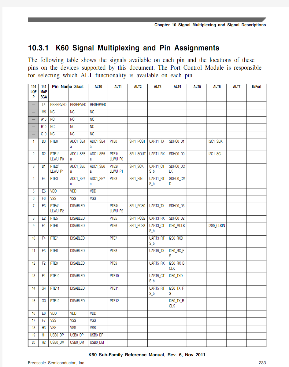
The following table shows the signals available on each pin and the locations of these pins on the devices supported by this document. The Port Control Module is responsible for selecting which ALT functionality is available on each pin.
10.3.2K60 Pinouts
The below figure shows the pinout diagram for the devices supported by this document. Many signals may be multiplexed onto a single pin. To determine what signals can be used on which pin, see the previous section.