Synthesis and Hierarchical Structures of Amphiphilic
- 格式:pdf
- 大小:293.09 KB
- 文档页数:9
南京邮电大学硕士研究生学位论文摘要摘要近年来,水溶性共轭高分子显示出的独特光电性质在化学生物传感器中获得了广泛的应用,由于水溶性共轭聚合物可溶于水等环境友好溶剂,通过聚合物与带相反电荷猝灭剂之间的电子或能量转移对周围环境中微量物质进行检测,而电子或能量极易在整个聚合物链上离域,荧光猝灭信号被放大,因此可以简便实现对多种有机、无机甚至生物大分子的高灵敏度检测。
从水溶性共轭高分子的结构设计来看,多支化构型的发光共轭高分子能够更好的改善线型高分子由于聚集引起的荧光自身猝灭,从而更好的提高水溶性共轭高分子传感材料的抗干扰能力和检测灵敏度。
另一方面,水溶性共轭聚合物作为高灵敏度传感材料在酶的检测方面具有信号倍增和实时检测的优势,可大大提高酶检测方法的灵敏度、方便性和广谱性。
本论文从制备多支化水溶性共轭高分子入手,设计合成新型阳离子型水溶性共轭聚芳撑乙炔,同时利用某些已制得的水溶性共轭高分子进行新的生物传感应用探索。
主要研究工作包括以下几个方面:1.将超支化反应的方法引入到水溶性共轭高分子的设计合成中,利用单体A2 + A2’ + B3的方法,先通过Sonogashira聚合得到中性超支化共轭聚合物,然后进行季胺化得到水溶性超支化共轭聚合物。
2.利用已制得的阳离子型水溶性共轭聚合物PFEP与酶底物探针的相互作用检测磷酸酯酶。
由于聚合物可以通过静电吸引与荧光素修饰的带负电荷的三磷酸腺苷结合并发生荧光共振能量转移。
当加入磷酸酯酶时,它可以催化底物三磷酸腺苷上的磷酸酯基团逐渐水解,得到不带电荷的腺苷,从而使阳离子型共轭聚合物得以释放,能量转移效率下降。
结果表明,能量转移效率下降的程度与酶的浓度相关,该方法灵敏度高,检测限可达到1 × 10⁻⁶ unit/µL。
关键词:水溶性共轭聚合物,超支化,合成,荧光检测,传感,酶ABSTRACTIn recent years, water-soluble conjugated polymers (WSCP) have been used as chemical and biological sensors due to their unique optical and electrical properties. Because of WSCP is soluble in water and other environment-friendly solvent, micro substances can be detected through between the polymer and the oppositely charged-quencher. Hence electronic or energy transfer tends to delocalize easily throughout the polymer chain and fluorescence quenching signal is amplified, thus high-sensitivity detection of a variety of organic or inorganic and even biological macromolecules can be easily achieved. From the structural design of point, the multi-branched WSCP can improve the self-quenching of fluorescence causing by configuration compared to the linear WSCP. Consequently, the anti-interference ability and detection sensitivity can also be increased when WSCP is applied as sensory materials. On the other hand, as sensing materials with high sensitivity, WSCP has the advantages of real-time and signal-amplified in the detection of the enzyme using. As a result, the enzyme assay high sensitivity, convenience and wide-spectrum can all be achieved by WSCP. In the thesis, we prepared multi-branched water-soluble conjugated polymers first, besides this, we have designed a novel sensing method using of cationic water-soluble conjugated aromatic acetylene which has been obtained. This dissertation is focused on modifying the aggregation of WSCPs by means of structure design and changing environmental conditions, and studying the structure-property relationship. The contents are as follows:1. Hyperbranched reaction method is introduced to the design of water-soluble conjugated polymer synthesis. The synthesis of water-soluble conjugated hyperbranched polymer was adopted A2 + A2' + B3 method. At first, AB n monomer with conjugated aromatic structures was synthesized and then polymer was obtained by one-step reaction. In the beginning, the neutral polymer was gained through Sonogashira polymerization, and then got water-soluble conjugated polymers from post-quaternization treatment.2. The cationic conjugated polymer (CCP) associated with the fluorescein-labeled anionic adenosine triphosphate (ATP) by electrostatic attractions and fluorescence resonance energy transfer (FRET) from the CCP to the fluorescein-labeled ATP occurred. When phosphatase was added, it catalyzed the hydrolysis of phosphate groups from its substrate, ATP, and the final productadenosine was neutral, which made the CCP detached from adenosine. Then the FRET efficiency decreased. The results showed that the degree of FRET efficiency decrease was related to the concentration of phosphatase, the detection limit can be 1×10⁻⁶ unit/µL.Keywords: Water-soluble conjugated polymers, Hyperbranched, Synthesize, Fluorescence detection, Sensory,Enzyme南京邮电大学学位论文原创性声明本人声明所呈交的学位论文是我个人在导师指导下进行的研究工作及取得的研究成果。
药学专业文献翻译Enzymatic Synthesis and Antioxidant Properties of Poly (rutin) 聚(芦丁)的酶促合成与抗氧化性质†‡†‡††Motoichi Kurisawa, Joo Eun Chung, Hiroshi Uyama,* and Shiro Kobayashi*Abstract 摘要Rutin, quercetin-3-rutinoside, is one of the most famous glycosides of flavonoid and widely present in many plants. In this study, we performed an oxidative polymerization of rutin using Myceliophthora laccase as catalyst in a mixture of methanol and buffer to produce a flavonoid polymer and evaluated antioxidant properties of the resultant polymer. Under selected conditions , the polymer with molecular weight of several thousands was obtained in good yields. The resulting polymer was readily soluble in water, DMF, and DMSO, although rutin monomer showed very low water solubility. UV measurement showed that the polymer had broad transition peaks around 255 and 350 nm in water, which were red-shifted in an alkaline solution. Electron spin resonance (ESR) measurement showed the presence of a radical in the polymer. The polymer showed greatly improved superoxide scavenging activity and inhibition effects on human low-density lipoprotein (LDL) oxidation initiated by 2,2‘-azobis(2-amidino-propane) dihydrochloride (AAPH), compared with the rutin monomer. The polymer also protected endothelial cells from oxidative injuryinduced by AAPH as a radical generator with a much greater effect than the rutin monomer.芦丁,槲皮素芸香糖苷,是最著名的黄酮类糖苷之一,广泛存在于很多植物中。
硅酸盐学报· 1730 ·2009年新型镍锡铝水滑石的合成及还原性能潘国祥1,2,倪哲明2,曹枫1,李小年2(1. 湖州师范学院化学系,浙江湖州 313000;2. 浙江工业大学化学工程与材料学院,杭州 310032)摘要:通过改变Ni/Sn和(Ni+Sn)/Al的摩尔比,采用共沉淀法成功合成了新型NiSnAl水滑石(layered double hydroxides,LDHs)。
当n(Ni)/n(Sn)≥16和n[(Ni+Sn)]/n(Al)=2~5时可制备纯水滑石相材料。
当n(Ni)/n(Sn)≤12时,合成样品中除存在水滑石相外,还伴随有SnO杂相。
合成的Ni20SnAl7– LDHs样品形貌呈六边形,其尺寸约为80nm,并且分散性良好。
热重–差热分析显示:在Ni3Al–LDHs基础上添加Sn,其热稳定性变差;随着n[(Ni+Sn)]/n(Al)增大,水滑石层板羟基及层间碳酸根的热分解温度降低。
H2程序升温还原分析表明:样品还原过程包含2个阶段,低温还原峰对应于Ni/Sn 从水滑石层板中直接还原,高温还原峰则为Ni/Sn从氧化物NiSnAl(O)中还原。
并且Sn含量越高,Al含量越低,NiSnAl–LDHs样品越容易被还原。
关键词:镍锡铝水滑石;合成与表征;热稳定性;还原特性中图分类号:O611.6 文献标志码:A 文章编号:0454–5648(2009)10–1730–05SYNTHESIS AND REDUCTIVE PROPERTIES OF NEW Ni–Sn–Al LAYERED DOUBLE HYDROXIDESP AN Guoxiang1,2,NI Zheming2,CAO Feng1,LI Xiaonian2(1. Department of Chemistry, Huzhou Teachers College, Huzhou 313000, Zhejiang; 2. College of Chemical Engineering andMaterials Science, Zhejiang University of Technology, Hangzhou 310032, China)Abstract: New Ni–Sn(Ⅱ)–Al layered double hydroxides (NiSnAl–LDHs) were successfully synthesized using coprecipitation by modifying the mole ratio of n(Ni)/n(Sn) and n(Ni+Sn)/n(Al). The synthesized materials with unitary hydrotalcite phase can be ob-tained if n(Ni)/n(Sn)≥16 or n(Ni+Sn)/n(Al)=2–5. When n(Ni)/n(Sn)≤12, the synthesized samples contain a SnO phase as well as a hydrotalcite phase. The structure of Ni20SnAl7–LDHs particles is hexagonal and the powders are well dispersed with a size of 80nm. Sn-substituted LDHs samples showed less thermal stability compared to Ni3Al–LDHs. With the ratio of n(Ni+Sn)/n(Al) increasing, the de-composition temperature of the hydroxyl layer and interlayer carbonate decreased. The H2–TPR (temperature programmed reduction) char-acterization of NiSnAl–LDHs showed that the reductive process of LDHs contains two steps. The low-temperature reductive peak seems to be resulted from the direct reduction of Ni/Sn ions within the layers, while the high-temperature reductive peak seems to be resulted from the reduction of NiSn(O). Additionally, the NiSnAl–LDHs tend to be reduced as the Sn content increases or the Al content decreases.Key words: nickel–tin–aluminum layered double hydroxides; synthesis and characterization; thermal stability; reductive property水滑石类材料(layered double hydroxides,LDHs),也称层状阴离子黏土,是一种重要的无机功能材料。
本科生科研训练题目高能量密度柔性赝电容器中的二维磷酸氧钒超薄结构(翻译)院系物理科学与技术学院专业物理学基地班年级2012级学生姓名李赫学号**********二0一三年十二月二十日natureCOMMUNICATIONS2013年2月5号收到稿件2013年8月12日接受稿件2013年9月12日发表稿件DOI: 10.1038/ncomms3431高能量密度柔性赝电容器中的二维磷酸氧钒超薄结构二维材料一直以来在柔性薄膜型超级电容器,以及表现有关灵活性,超薄度甚至透明度的强劲优势上都是一个理想的构建平台。
要探索新的具有高电化学活性的二维赝电容材料,我们需要获得具有高能量密度的柔性薄膜超级电容器。
这里我们介绍一个无机石墨烯类似物,a1钒,一种少于6个电子层的磷酸盐超薄纳米片来作为一个有发展前景的材料去构建柔性全固态超薄赝电容器。
这种材料展示了一个在水溶液中氧化还原电位(~1.0V)接近纯水电化学窗口电压(1.23V)的赝电容柔性平面超级电容器。
通过层层组装构建出的柔性薄膜型超级电容器的氧化还原电位高达1.0V,比容量高达8360.5 μF∙cm-2,能量密度达1.7 mWh ∙cm-2,功率密度达5.2 mW∙cm-2。
现在,便携式消费电子产品的需求在快速增长,如柔性显示器,手机和笔记本电脑,极大推动了在全固态下的柔性能源设备的开发。
作为未来一代的储能装置,柔性薄膜型超级电容器在全固态下提供柔韧性,超薄型和透明度的协同效益。
在不同的类型的超级电容器中,与电双层电容器相比,赝电容器因为自身的高活性表面的电极材料可以快速发生的氧化还原反应而具有明显优势。
与锂离子电池相比,它表现出更高的能量密度,以及更高的功率密度。
因此,承载着为实现高性能的柔性薄膜型超级电容器的全固态伟大的承诺(FUSA)与电容行为。
具有赝电容特性的二维(2D)类石墨烯材料代表着一个有前途的方向可以去实现全固态下的高能量密度柔性超级电容器,和潜在的优良的机械柔性。
化工进展Chemical Industry and Engineering Progress2024 年第 43 卷第 4 期具有烷基磺酸侧链的凝胶型聚苯并咪唑质子交换膜的制备与表征朱泰忠1,张良1,黄泽权1,罗伶萍1,黄菲1,薛立新1,2(1 浙江工业大学化工学院膜分离与水科学技术中心,浙江 杭州 310014;2温州大学化学与材料工程学院,浙江 温州 325035)摘要:磷酸(PA )掺杂聚苯并咪唑(PBI )以其优异的热化学稳定性和高玻璃化转变温度成为高温质子交换膜燃料电池(HT-PEMFCs )的首选材料。
然而,由于低温下磷酸较弱的解离度和传递速率,导致膜的质子传导性能不佳,电池冷启动困难。
因此,研发可在宽温湿度范围内高效运行的高温质子交换膜成为当前挑战。
特别是拓宽其低温运行窗口、实现冷启动对这类质子交换膜燃料电池在新能源汽车领域的实际应用具有重要意义。
本文通过多聚磷酸溶胶凝胶工艺与内酯开环反应设计并合成了一系列磷酸掺杂的具有柔性烷基磺酸侧链的凝胶型聚苯并咪唑质子交换膜。
重点探究了烷基磺酸的引入以及侧链长度对磷酸掺杂水平、不同温湿度下的质子传导率及稳定性的影响规律。
研究结果表明,所制备的质子交换膜具有凝胶型自组装片层堆叠的多孔结构,有利于吸收大量磷酸并提供质子快速传输通道。
其中,PA/PS-PBI 展现出了在宽温域范围内均优于目前所报道的其他工作的质子传导性能。
特别是常温下,其质子传导率从原膜的0.0286S/cm 提升至0.0694S/cm 。
80℃下,其质子传导率从原膜的0.1117S/cm 提升至0.1619S/cm 。
200℃下,其质子传导率从原膜的0.2609S/cm 提升至0.3578S/cm 。
此外,该膜在80℃和0%相对湿度(RH )条件下仍可具有与Nafion 膜在100%RH 时相当的质子传导率,为打破质子交换膜经典定义、实现宽温域(25~240℃)运行提供新的方案。

齐齐哈尔大学毕业设计(论文)题目年产6万吨2-丙基庚醇车间合成工段工艺初步设计学院化学与化学工程专业班级学生姓名指导教师成绩2013 年 6 月日摘要本课题是年产6万吨2-丙基庚醇车间合成工段工艺的初步设计。
第一论述了二丙基庚醇合成的意义与作用、国内外研究现状及进展前景,并简要介绍了二丙基庚醇的性质及合成方式,第二介绍了课题的设计背景、厂址选择和原料产品规格;通过国内外几种相关工艺的比较肯定本设计的工艺流程,对整个生产进程进行了物料衡算、热量衡算和Aspen plus模拟;对反映釜等主要设备进行了设备计算与选型,而且对车间设备进行了布置,对自动控制、安全和环境保护和公用工程进行了概述。
最后按照毕业设计的要求利用AutoCAD绘制戊醛缩合反映釜装配图和合成工段设备平立面布置图,手绘了带控制点的工艺流程图,而且完成了20 000字的毕业设计说明书。
关键词:初步设计;合成工段;2-丙基庚醇;衡算AbstractThe preliminary design of workshop of the synthesis section of 60,000 tons annual production capacity of 2-propyl heptanol was completed. Firstly, the significance, the function of 2-propyl heptanol, the development of research on 2-propyl heptanol was stated. The nature of 2-propyl heptanol and synthetic methods were described briefly. Secondly, the design background, plant location and materials and product specification were introduced; comparion of the productive processed in the domestic and aboard, the design process was determined. Meanwhile the material balance, heat balance, and the simulation of process by Aspen plus were finished. The reactor equipment and other major equipments were calculated and selected. And the layout of the equipment for the workshop, safety, environmental protection and public works were outlined. Thirdly, the equipments arrangement diagram of the workshop and the pentanal condensation reactor equipment were drawn with Auto CAD, the process flow diagram with control points was drawn by hand. Finally, the design instruction of 20 thousand words was finished.Key words:Preliminary design; Synthesis section; 2 - propyl heptanol; Balance calculation目录摘要 (I)Abstract (II)第一章总论 (1)概述 (1)项目建设意义 (1)国内外现状及进展前景 (1)设计依据 (3)厂址选择 (4)厂址肯定 (4)厂址优势分析 (4)设计规模与生产制度 (5)设计规模 (5)生产制度 (5)原料和产品规格 (6)经济核算 (6)第2章工艺设计和计算 (7)工艺线路的选择 (7)2-丙基庚醇工艺介绍 (7)2-丙基庚醇工艺的肯定 (8)工艺流程简述 (8)物料衡算 (9)反映器R101的物料衡算 (9)分离罐V103的物料衡算 (10)换热器E101的物料衡算 (11)精馏塔T101的物料衡算 (12)换热器E104的物料衡算 (12)反映器R102的物料衡算 (13)换热器E105的物料衡算 (14)闪蒸罐V105的物料衡算 (15)热量衡算 (16)反映器R101的热量衡算 (16)换热器E101的热量衡算 (17)T101冷凝器E102的热量衡算 (18)T101再沸器E103的热量衡算 (19)精馏塔T101的热量衡算 (21)换热器E104的热量衡算 (22)反映器R102的热量衡算 (24)换热器E105的热量衡算 (25)全流程模拟 (26)总工艺的模拟 (26)反映器R101的模拟 (27)精馏塔T101的模拟 (28)反映器R102的模拟 (28)第3章设备计算及选型 (30)关键设备R101计算及选型 (30)R101筒体直径和高度的计算 (30)筒体壁厚的计算 (30)夹套的计算 (31)水压实验及强度校核 (32)换热计算 (33)釜体法兰的选择 (33)搅拌器的选择 (33)搅拌传动装置和密封装置的选择 (34)容器支座的选择 (35)人孔、视镜、温度计和工艺接管的选择 (35)其他设备计算与选型 (36)反映器R102的计算 (36)精馏塔T101的计算 (37)换热器的计算与选型 (40)泵计算与选型 (43)储罐和回流罐的计算与选型 (44)紧缩机C101的计算与选型 (46)第4章设备一览表 (47)第5章车间布置 (49)反映器和塔的布置 (49)换热器的布置 (50)泵和紧缩机的布置 (50)罐的布置 (51)第6章自动控制 (52)2-丙基庚醇合成工段自动控制 (52)泵P101的控制 (52)塔顶冷凝器E102的控制 (52)反映器R101的控制 (53)精馏塔T101的控制 (53)第7章公用工程 (55)供水 (55)供热 (55)供电 (56)第8章安全环境保护 (57)结束语 (58)参考文献 (59)致谢 (61)第一章总论概述项目建设意义分子总碳数为4~13的脂肪族伯醇,其全世界近50%产量用于生产增塑剂,所以国内外俗称其为增塑剂醇[1]。
Transactions of Tianjin University (2019) 25:237–244https:///10.1007/s12209-018-0169-zS trategy for Synthesizing Novel Acetamidines as C O 2 -Triggered Switchable Surfactants via AcetimidatesY an X u 1 · F an W ang 1 ·Q ingfeng H ou2 · Y ujun Z hao 1 ·G uosheng D ing3 · X ingguang X u 4R eceived: 15 March 2018 / Revised: 28 April 2018 / Accepted: 3 May 2018 / Published online: 15 June 2018©T he Author(s)2018A bstractI n this study, we developed a strategy for using the Scoggins procedure in the synthesis of acetamidines as novel C O 2 -triggered switchable surfactants via acetimidates by eff ectively tuning the chemical equilibrium. The as-synthesized N’-alkyl- N,N-diethylacetamidines exhibit excellent C O 2 /N 2 switchability and their bicarbonate salts have the ability to emulsify oil–water mixtures.K eywords C O 2 switchable surfactants · A cetimidate · A cetamidine · C onsecutive reactionI ntroductionS urfactants, whose amphiphilic structures enable the stabili-zation of emulsions with two immiscible phases, are widely applied in many processes such as cleaning [ 1], viscous oil transportation [ 2], and enhancing oil recovery [ 3]. Excellent stabilization is required in these processes, usually followed by a subsequent emulsion-destabilization step to eff ectively recover the two immiscible phases. However, this remains a challenging task for most commonly used surfactants. To tackle this problem, it is necessary for the surfactants that can be “switched on and off ” to reversibly stabilize/desta-bilize the emulsion under certain trigger conditions. The switchable surfactants reported in the literature can undergo reversible interconversions from surface-active to surface-inactive forms upon command, and their switchability can usually be triggered by altering the external conditions, such as pH [ 4], electrochemical redox [ 5], magnetic-fi eld intensity [ 6], or light source (UV or visible light) [ 7]. Com-pared with these triggers, C O 2 is environmentally benign, inexpensive, and renewable, and more important, it does not accumulate in a system after repeated cycles. Therefore, it has been identifi ed as an innovative and ideal “trigger” for stimuli-responsive surfactants and has recently been studied for use in reversible solvents [ 8–10 ], switchable Pickering emulsions [ 11 ,12 ], and repeatable polymer-based materials [ 13 ,14 ], particularly for application in enhanced oil recov-ery[15,16].T hus far, the majority of C O 2 /N 2 reversible surfactants include guanidines, imidazoles, tertiary amines, and ami-dines. In their inactive forms, these surfactants can be pro-tonated to form charged bicarbonates that become active upon the addition of C O 2 in aqueous media, increasing their solubility in water. The bicarbonate ions can then be deprotonated by bubbling with N2 or air [ 17 ]. However, these common C O 2 /N 2 reversible surfactants have some inherent drawbacks that hinder their wide application. The headgroup of imidazole surfactants limits their triggering effi ciency due to their hydrolysis in aqueous media [ 18 ]. Surfactants containing a hydrophilic headgroup of guani-dine are generally basic and require more rigorous condi-tions to achieve deprotonation (such as high temperature, long reaction time, or heavy fl ow rate of bubbling gas) [ 19 ].E lectronic supplementary material T he online version of thisarticle ( h ttps :///10.1007/s1220 9-018-0169-z )containssupplementary material, which is available to authorized users.*Q ingfeng H ouh ouqingfeng@*Y ujun Z haoy ujunzhao@1K ey Laboratory for Green Chemical Technology of Ministryof Education, Collaborative Innovation Center of ChemicalScience and Engineering, School of Chemical Engineeringand T echnology,T ianjin University,T ianjin 300072,C hina2 R esearch Institute of Petroleum Explorationand Development (RIPED) ,C NPC ,B eijing 100083 ,C hina3 A nalysis Center ,T ianjin University ,T ianjin 300072 ,C hina4 E nergy Business Unit ,C SIRO ,K ensington ,W A 6151 ,A ustralia1 3238 Y. Xu et al.1 3With respect to tertiary amines, their basicity is so weak that stable emulsions can hardly be formed [ 20 ]. As such, compounds containing an amidine head [ 21 , 22 ] are attract-ing more attention due to their mild basicity and superior stability. In addition, the exceptional demulsifying ability of amidines in their neutral form is an unexpected advan-tage. Scheme 1 illustrates the protonation and deprotonation processes of amidines stimulated by C O 2and N 2 (or air), respectively, in aqueous media, where R represents a long-chain alkyl or ethoxylated groups. Amidine surfactants can easily and reversibly transform into bicarbonate salts. A midines can be synthesized using various strategies, such as the nucleophilic addition of amines to nitriles [ 23 ], reaction of catalytic three-component coupling [ 24 ], dis-placement reaction of imidates with amines [ 25 , 26 ], and the Scoggins procedure [ 27 , 28 ]. Of these synthetic meth-ods, the Scoggins procedure involving primary amines and N , N -dimethylacetamide dimethyl acetal can synthesize long-chain aliphatic amidines and aromatic amidines with a high yield of 90% accompanied by the formation of a small amount of imidates as a by-product [ 27 , 28 ]. This is par-ticularly attractive since an encouraging acetamidines yield of 99% was achieved by Jessop et al. [ 21 ] when they added an excess amount of dimethylamine to the reaction sys-tem. However, the types of amidines used in this synthesis method have been fairly limited thus far, due to the limita-tion of commercially available reactants. The structure of amidines generated by this method diff ered from those in the hydrophobic tail group, which are mainly long-chain alkyl or ethoxylated groups, or both [ 16 , 21 ], and the hydrophilic head is bonded only with the dimethyl group. A s stated earlier, imidates were the only by-product of the Scoggins procedure. At the same time, the potent elec-trophilicity of imidates supports the synthesis of amidines through displacement reactions with amines. Therefore, imi-dates have potential for use in the synthesis of new C O 2 /N 2switchable amidines if various imidates can be generated as the main product by modifying the Scoggins procedure. We also believe it is important to gain insight into the reaction path of the Scoggins procedure to facilitate the development of this novel synthesis strategy. In this study, we mainly investigated the reaction path of the Scoggins procedure foruse in developing a new approach for the synthesis of novel C O 2 /N 2switchable surfactants. E xperimental Section M aterials and Methods To avoid light and moisture, we conducted all the reactions in the dark environment. We purchased N , N -dimethylaceta-mide dimethyl acetal (> 90%, stabilized by 5–10% methanol) and a series of primary amines (dodecylamine (AR) > 98%, tetradecylamine (AR) > 96%, hexadecylamine (AR) > 95%, octadecylamine (GC) > 98%) from Aladdin Reagent Com-pany (Shanghai, China) without further purifi cation. We pre-pared N ’-dodecyl- N , N -dimethylacetamidine ( 1b ) in experi-ments 1 and 2, as shown in Table 1 , according to methods reported in Refs. [ 21 , 28 ]. We recorded the proton nuclearmagnetic resonance ( 1H NMR) and carbon-13 nuclear mag-netic resonance ( 13C NMR) of the reaction products on a Varian Inova spectrometer (Varian, America, 500 MHz), forwhich all the chemical shift values refer to C DCl 3( δ ( 1H), 7.26 ppm; δ ( 13C), 77.16 ppm). We obtained high-resolution electrospray ionization mass spectrometry (ESI-HRMS) data on a Bruker micrOTOF-QII mass spectrometer (Bruker, America) and infrared (IR) spectra on a Nicolet Avatar 320 spectrometer (Thermo Fisher, America) with a smart miracle accessory.G eneral Procedure for the Synthesis of N -alkyl- O -MethylacetimidatesW e put N , N -dimethylacetamide dimethyl acetal (1.72 g, 0.012 mol) and dodecyl amine (1.89 g, 0.01 mol) into a three-neck round-bottom brown fl ask in a dark environment and an oil bath, to which we then added methanol (40 mL). We kept this mixture at 68 °C for 2 h with a methanol refl ux in the condenser. To determine when the conversion of the dodecylamine was complete, we used the thin-layer chromatography method (Merck TLC plates, silica gel 60 F254, with chloroform and methanol as developing sol-vents, V CHCl3 / V CH3OH = 3:1). Then, we removed the metha-nol and dimethylamine from the reaction mixture by rotary evaporation at 50 °C and − 0.1 MPa for 20 min, obtaining a light-yellow liquid product consisting of N -dodecyl- O -methylacetimidate ( 1a , 71.7% yield) and N ’-dodecyl- N , N -dimethylacetamidine ( 1b , 28.3% yield). We calculated theyield based on its 1H NMR spectrum. Then, we subjected the resulting mixture to fl ash column chromatography on aluminum oxide (active, neutral, 200–300 mesh) using ethyl acetate and dichloromethane ( V CH3COOCH2CH3 / V CH2Cl2 = 1:2) as mobile phases to obtain purifi ed N -dodecyl- O -methyl-acetimidate ( 1a )as a colorless liquid. We also synthesizedS cheme 1P rotonation and deprotonation processes of amidines andbicarbonate salts239Strategy for Synthesizing Novel Acetamidines as C O 2 -Triggered Switchable Surfactants… 1 3other N -alkyl- O -methylacetimidates, including N -tetradecyl- O -methylacetimidate ( 2a ), N -hexadecyl- O -methylacetimi-date ( 3a ), and N -octadecyl- O -methylacetimidate ( 4a ), by the same method, using diff erent primary amines as the reactants, i.e., tetradecylamine (0.22 g), hexadecylamine (0.25 g), and octadecylamine (0.28 g), respectively.N -dodecyl- O -methylacetimidate ( 1a ): Colorless oil, 1H NMR (500 MHz, C DCl 3) δ = 7.27 (s, 1H), 3.60 (s, 3H), 3.18 (t, 2H), 1.86 (s, 3H), 1.54–1.49 (m, 2H), 1.33–1.26(m, 18H), 0.88 (t, 3H); 13C NMR (125 MHz, C DCl 3 )δ = 161.10, 77.67–76.74, 52.07, 49.40, 32.13, 31.74, 29.90, 29.87, 29.86, 29.77, 29.57, 27.54, 22.89, 14.59, 14.28; HRMS m/z (ESI) calcd for C 15 H 31NO (M + H) + 242.2478, found 242.2512. IR absorption W –N=C– at 1685.48 cm −1,W –C–O–C– at 1253.50 cm −1. N -tetradecyl- O -methylacetimidate ( 2a ): Colorless oil, 1H NMR (500 MHz, C DCl 3) δ = 7.27 (s, 1H), 3.60 (s, 3H), 3.18 (t, 2H), 1.86 (s, 3H), 1.55–1.49 (m, 2H), 1.30–1.26 (m,22H), 0.88 (t, 3H); 13C NMR (125 MHz, C DCl 3) δ = 161.02, 77.67–76.74, 52.07, 49.50, 32.04, 31.57, 29.81, 29.78, 29.68, 29.49, 27.51, 22.79, 14.47, 14.17; HRMS m/z (ESI) calcd for C 17 H 35NO (M + H) + 270.2791, found 270.2811; IR absorption W –C=N– at 1685.48 cm −1, W –C–O–C–at 1253.50 cm −1. N -hexadecyl- O -methylacetimidate ( 3a ): Colorless oil, 1H NMR (500 MHz, C DCl 3) δ = 7.27 (s, 1H), 3.60 (s, 3H), 3.17 (t, 2H), 1.86 (s, 3H), 1.59–1.49 (m, 2H), 1.30–1.26(m, 26H), 0.88 (t, 3H); 13C NMR (125 MHz, C DCl 3 )δ = 161.17, 77.67–76.74, 52.21, 49.53, 32.16, 31.68, 29.94, 29.90, 29.89, 29.79, 29.61, 27.63, 22.91, 14.63, 14.30; HRMS m/z (ESI) calcd for C 19 H 39NO (M + H) + 298.3104, found 298.3128; IR absorption W –C=N–at 1685.48 cm −1, W –C–O–C– at 1253.50 cm −1.N -octadecyl- O -methylacetimidate ( 4a ): Colorless oil, 1H NMR (500 MHz, C DCl 3) δ = 7.27 (s, 1H), 3.58 (s, 3H), 3.17 (t, 2H), 1.85 (s, 3H), 1.54–1.49 (m, 2H), 1.30–1.25(m, 30H), 0.88 (t, 3H); 13C NMR (125 MHz, C DCl 3 ) δ = 161.01, 77.67–76.74, 52.14, 49.51, 32.16, 31.71, 29.94, 29.90, 29.79, 29.61, 27.63, 22.91, 14.56, 14.28; HRMS m/z (ESI) calcd for C 21 H 43NO (M + H) + 326.3417, found 326.3444; IR absorption W –C=N– at 1685.48 cm −1,W –C–O–C– at 1253.50 cm −1.G eneral Procedure for Reaction Pathway Studies Using 1 H NMRE xperimental Process for the Results Shown in Fig. 1 W e added N , N -dimethylacetamide dimethyl acetal (1.72 g) and dodecyl amine (1.89 g) to a three-neck round-bottom brown fl ask in a dark environment, to which we added 40 mL of methanol. Then we maintained the mixture at 68 °C for 2 h by controlling the temperature of the oil bath with a methanol refl ux in the condenser. We extracted 1 mL samples at intervals and immediately transferred them into an ice bath. Then, we removed the methanol and dimethylamine from the samples using a rotary evapora-tor at 10 °C and − 0.1 MPa. The remaining product was a mixture of N -dodecyl- O -methylacetimidate ( 1a ) and N ’-dodecyl- N , N -dimethylacetamidine ( 1b ). Based on their 1 H NMR spectra, we calculated the selectivities of 1a and 1b at different reaction times.T able 1P roduct distribution results using the Scoggins procedureaC onversion of dodecylaminebY ield of 1a was calculated based on the relative integration of the peak at δH = 3.60 (the group of –O(CH 3)) [ 29 ] with respect to the peak at δH = 2.87 (the group of –N(CH 3 ) 2 ) [ 21 ]cY ield of 1b was calculated based on the relative integration of δH = 2.87 with respect to δH = 3.60240 Y. Xu et al.1 3E xperimental Process for the Results Shown in Fig. 2F irst, we prepared a certain amount of purifi ed N ’-dode-cyl- N , N -dimethylacetamidine ( 1b ) using the methoddeveloped by Jessop et al. [ 21 ]. We added about 0.012 mol of N , N -dimethylacetamide dimethyl acetal (1.72 g) and 76.4 mmol of M e 2NH (38 mL, 2 mol/L solution in tet-rahydrofuran) into a three-neck round-bottom brown fl ask and stirred the mixture (100 r/min) at 25 °C. After that, we added about 0.01 mol dodecylamine (1.89 g) drop-wise to this mixture at room temperature, stirred it for 10 min, and then left it for 18 h in the dark. To remove most of the tetrahydrofuran and M e 2NH, we kept the mixture at 55 °C and − 0.1 MPa in a rotary evaporator for 8 h, which yielded a yellow liquid consisting of N ’-dodecyl- N , N -dimethylacetamidine ( 1b , yield = 97.6%) anda trace impurity of N -dodecyl- O -methylacetimidate ( 1a ,yield = 2.4%), which we identifi ed based on its 1H NMR spectrum. We then reacted the above product (2.54 g) with methanol (40 mL) in a three-neck round-bottom brown fl ask with a condenser and thermometer and kept this mixture at 68 °C for 2 h. We extracted 1 mL samples at intervals, which we immediately transferred into an ice bath. Then, we removed the methanol and dimethylamine from the samples using a rotary evaporator at 10 °C and−0.1 MPa. By 1H NMR, we identifi ed the remaining prod-uct as a mixture of N -dodecyl- O -methylacetimidate ( 1a ) and N ’-dodecyl- N , N -dimethylacetamidine ( 1b ). Based ontheir 1H NMR spectra, we calculated the normalized con-centrations of 1a and 1b at different reaction times.G eneral Synthesis of N ’-Alkyl- N , N -DiethylacetamidinesW e obtained purifi ed N -hexadecyl- O -methylacetimidate ( 3a ) and N -octadecyl- O -methylacetimidate ( 4a ) by the method described above in section “ G eneral Procedure for the Synthesis of N -alkyl- O -Methylacetimidates ”. We put the obtained N -hexadecyl- O -methylacetimidate (1.48 g, 0.005 mol) into a three-neck round-bottom brown fl ask and reacted it with diethylamine (7.31 g, 0.1 mol) in the solvents triethylamine (20 mL) and dioxane (30 mL) at 85 °C (reaction temperature) for 36 h. After the reaction, we removed the volatile components from the mixture, including diethylamine and the solvents triethylamine and dioxane, using a rotary evaporator at 60 °C and −0.1 MPa for 30 min, obtaining N ’-hexadecyl- N , N -diethylacetami-dine ( 3c , 60.5% yield) as a yellow liquid. We also syn-thesized N ’-octadecyl- N , N -diethylacetamidine ( 4c , 53.7% yield) by the same method, using 1.63 g N -octadecyl- O -methylacetimidate (0.005 mol) as the reactant. N ’-hexadecyl- N , N -diethylacetamidine ( 3c ): Yellow oil, 1 H NMR (500 MHz, C DCl 3) δ = 7.27 (s, 1H), 3.29 (q, 4H), 3.17 (t, 2H), 1.87 (s, 3H), 1.52–1.47 (m, 2H),1.30–1.26 (m, 26H), 1.08 (t, 6H), 0.88 (t, 3H); 13C NMR (125 MHz, C DCl 3) δ = 156.57, 49.73, 41.68, 32.31, 31.46, 29.68–27.38, 22.65, 14.34, 14.04, 13.67; HRMS m/z (ESI) calcd for C 22 H 46NO (M + H) + 339.3733, found 339.3752; IR absorption W –N=C–N– at 1620.76 cm −1. N ’-octadecyl- N , N -diethylacetamidine ( 4c ): Yellow oil, 1H NMR (500 MHz, C DCl 3) δ = 7.27 (s, 1H), 3.29 (q, 4H), 3.17 (t, 2H), 1.88 (s, 3H), 1.53–1.48 (m, 2H),1.30–1.26 (m, 30H), 1.08 (t, 6H), 0.88 (t, 3H); 13C NMR (125 MHz, C DCl 3) δ = 156.55, 49.77, 41.63, 32.32, 31.89, 29.67– 26.94, 22.64, 14.34, 14.03, 13.67; HRMS m/z (ESI) calcd for C 22 H 46NO (M + H) + 367.4046, found 367.4064; IR absorption W –N=C–N– at 1621.46 cm −1.F ig. 1 P roduct distributions of 1a and 1b as a function of reactiontime in the Scoggins procedure in the presence of methanolF ig. 2 N ormalized concentrations of 1a and 1b as a function of reac-tion time in the reaction between acetamidine and methanol241Strategy for Synthesizing Novel Acetamidines as C O 2 -Triggered Switchable Surfactants…1 3G eneral Procedure for the Switchable Characterization Tests on N ’-Octadecyl- N , N -DiethylacetamidineWe determined the conductivity of the solution bubbled by C O 2 or N 2 using a DDSJ-308F conductivity meter (Shanghai Leici, China) and controlled the gas-fl ow rate using a mass fl ow controller (Beijing Shengye, China). We bubbled the solution of DMSO and water ( V DMSO / V water = 45 mL/5 mL) with N ’-octadecyl- N , N -diethylacetamidine ( 4c , 0.22 g) by C O 2 , followed by N 2 at 65 °C, during which we recorded the conductivity. We obtained four reversible cycles by bubbling C O 2 (400 mL/min) for 40 min and then N 2(800 mL/min) for 40 min. We also determined the conductivity of the solution containing purifi ed N -octadecyl- O -methylacetimidate ( 4a , 0.08 g) using the same method as that in the blank experi-ment. We examined the capability of stabilizing an emulsion by mixing dodecane and water (5 mL, v / v = 1:1) contain-ing N ’-octadecyl- N , N -diethylacetamidine ( 4c , 0.022 g) and observed the state of the oil–water emulsion layers formed by the bubbling C O 2at diff erent stages. R esults and Discussion C onsecutive Reactions of Scoggins Procedure in the Presence of Excess MethanolT o eff ectively regulate product distribution in the Scoggins procedure, we conducted this reaction by varying the organic additives. Table 1 summarizes the reaction results based onthe 1H NMR characterization. Compared with the results (Fig. S2) obtained in experiment 1 using the Oszczapow-icz’ method [ 28 ] without any additives, we obtained a high N ’-dodecyl- N , N -dimethylacetamidine ( 1b ) yield of about 97.6% (Fig. S3) when using NH(CH 3 ) 2 as the additive, as developed by the Jessop et al. [ 21 ]. It seems that NH(CH 3 ) 2 can inhibit the formation of N -dodecyl- O -methylacetimidate. Interestingly, the addition of methanol (experiment 3) led to a dramatic decrease in the yield of 1b , which represents only 28.3% of the total conversion of dodecylamine, whereas we found 1a to be the only by-product with a yield of 71.7% (Fig. S4). This remarkable decline in the acetamidine yield and the formation of such a large amount of acetimidate demonstrates that the presence of methanol may control the product distribution to a great extent. T o further understand the reaction path of the Scoggins procedure in the presence of excess methanol, we designed an experiment (experiment 3), in which we performed interval sampling during the reaction process to obtain a detailed product distribution as a function of the reactiontime. We used 1H NMR to analyze the relative selectivity of acetamidine and acetimidate during the reaction. Figure 1shows plots of the evolution of the selectivities of 1a and1b versus reaction time. In Fig. 1 , we can see that the selec-tivity of 1b increases rapidly to its peak within 2 min and then decreases slowly until reaching a constant selectivity of 28.1%, whereas the selectivity of 1a increases gradually until reaching 71.9% at 120 min. These results indicate that the process is likely a consecutive reaction, in which 1b is easily formed as an intermediate in the fi rst step and then reacts with methanol to generate 1a in the second step. The fact that 1b is readily generated in this reaction may be due to a bimolecular nucleophilic substitution reaction (SN2) between N , N -dimethylacetamide dimethyl acetal with high electrophilicity and the nucleophilic reagent dodecylamine. This reaction may be constrained by a thermodynamic equi-librium, in which the excess methanol in the mixture pro-motes the generation of acetimidates. T o better confi rm the consecutive reaction pathway of this reaction system, we performed a reaction between 1b (synthesized during experiment 2 in advance) and methanol.Using 1H NMR analysis, we identifi ed only 1a and 1b in the resulting mixture by after removing the volatile phase from the samples in high vacuum conditions. Figure 2 shows the normalized concentrations of 1a and 1b in the samples as a function of reaction time. We can see that the normal-ized concentration of 1b signifi cantly decreases with reac-tion time, reaching a constant value of about 28.3% after about 90 min. The normalized concentration of 1a shows the opposite trend at fi rst and ultimately remains constant at 71.7%. The time required to reach the equilibrium con-centration is about 90 min, which is shorter than that of the Scoggins procedure (120 min) in the conditions described above. These results indicate that 1a is generated from the reaction between 1b and methanol, thereby providing fur-ther evidence that the Scoggins procedure involves a con-secutive reaction. In addition, the higher selectivity of 1b at the beginning stage of the Scoggins procedure and the lower equilibrium yield of 1b due to the limiting eff ect of the thermodynamic equilibrium prove that the reaction of 1b with methanol in the second step is the control step for the formation of 1a . B ased on the above fi ndings, we successfully synthe-sized a class of N -alkyl- O -methylacetimidates ( A , Fig. S1) by enhancing the Scoggins procedure with the excess methanol (using the same reaction conditions as experi-ment 3 in Table 1 ). As listed in Table 2 , all the yields ofA are around 70% (Figs. S4–S7), which means that all these reactions reach roughly the same level of equilib-rium regardless of the diff erent hydrophobic groups of the primary amines. Next, we purifi ed a series of product A to colorless liquids using fl ash column chromatography withA l 2 O 3as the stationary phase and ethyl acetate/hexane ( v / v , 2:3) as the eluent. We then confi rmed the resultingstructures by HRMS (Figs. S8–S11), 1H NMR (Figs. S14,242Y. Xu et al.1 3S17, S20, S23), 13C NMR (Figs. S15, S18, S21, S24), and IR spectroscopy (Figs. S32–S35). Taking into considera-tion the characteristic of the equilibrium reaction, these acetimidates might have potential for use as precursors in the preparation of novel acetamidines via reactions with different primary or secondary amines.S ynthesis of Novel Acetamidines via AcetimidatesTo verify the feasibility of generating new acetamidines from acetimidates, we performed a series of reactions between purifi ed A and NH(CH 2 CH 3 ) 2 . As expected, we successfully produced two N ’-alkyl- N , N -diethylacetamidines ( C ) with a diethyl group linked to the amidine group for the fi rst time via a displacement reaction (Table 3 ) with anT able 2Y ield of A in experiment 3 of Table 1Entry R-group ProductsYield A a (%)Yield B b (%)Purity A c (%)1 C 12H 2571.728.31002 C 14H 2972.227.81003 C 16H 3370.429.61004 C 18H 3769.130.9100T he conversion of primary amines is 100% aT he acetimidates yield was calculated based on the relative integration of the peak at δH = 3.60 with respect to δH = 2.87, which represents the groups of –O(CH 3 ) and –N(CH 3 ) 2, respectively bT he acetamidines yield was calculated based on the relative integration of the peaks at δH = 2.87 and δH = 3.60 cW e observed no characteristic peak at δH = 2.87 T able 3P roduction of acetamidines from acetimidatesEntry R-group ProductsConversion A a (%)Yield C b (%)1C 16H 3360.560.52C 18H 3753.753.7T he selectivity to C is 100%, from which C is obtained as the exclusive productaT he conversion of acetimidates bT he yields of 3c and 4c were calculated from the relative integration of the quartet near δH = 3.30 (4H, –N(CH 2 CH 3 ) 2) [ 30 ] with the triplet atδH = 3.60 (3H, –OCH 3 ) based on the 1H NMR spectrum243Strategy for Synthesizing Novel Acetamidines as C O 2 -Triggered Switchable Surfactants…1 3extremely high selectivity of nearly 100%. We confi rmed the structures of N ’-hexadecyl- N , N -diethylacetamidine ( 3c ) and N ’-octadecyl- N , N -diethylacetamidine ( 4c ) by HRMS (Figs.S12, S13), 1 H NMR (Figs. S26, S29), 13C NMR (Figs. S27, S30) and IR spectroscopy (Figs. S36, S37). The quartets atδH = 3.29 in the 1H NMR spectra and at δC = 41.68 in the 13C NMR spectra indicate methylene in the -N(CH 2 CH 3 ) 2 group. We also detected solution peaks of trace 1,4-diox-ane at δH = 3.70 and δC = 67.03 [ 30 ]. This strategy opens a new possible way to design and effi ciently synthesize novel acetamidines with various terminal alkyl groups by simply replacing NH(CH 2 CH 3 ) 2with other dialkylamines. C O 2 -Triggered Switchable Characterization of Novel AcetamidinesN ext, we examined the C O 2 /N 2 switchability of N ’-octade-cyl- N , N -diethylacetamidine by monitoring the conductivity in wet dimethyl sulfoxide. As shown in Fig. 3 , N ’-octadecyl- N , N -diethylacetamidine ( 4c ) exhibited excellent switchabil-ity when C O 2 and then N 2were bubbled through the solution over four cycles, which indicates the reversible transforma-tion between neutral amidine and bicarbonate ions. We also examined the capability of N ’-octadecyl- N , N -diethylaceta-midine bicarbonates salts to stabilize an emulsion by mixing dodecane and water containing 4c . As shown in Fig. 4 , the two immiscible phases became a homogeneous emulsion after the bubbling of C O 2. When kept at room temperature for 12 h, the emulsion volume still accounted for about 90% of the oil–water system, including a thin cloudy liquid at the bottom of the measurement cylinder (Fig. 4 c ). Then, bubbling N 2 rapidly breaks the emulsion into two separate phases (Fig. 4 d ). The conductivity and emulsifi cation testscontaining only 4a evidenced that the rest of 4a had little eff ect and can be ignored. These results demonstrate that the synthesized N ’-alkyl- N , N -diethylacetamidines have C O 2 /N 2 switchability in the emulsifi cation and demulsifi cation of the oil–water system.C onclusionsIn conclusion, in this study, we developed a new approach for synthesizing C O 2-triggered switchable surfactants by the reaction between amines and imidates, produced using an enhanced Scoggins procedure. This reaction process consists of two reactions in a series, and the yield of acetimidates can be signifi cantly improved by shifting the reaction equilib-rium using excess methanol as an additive. This method pro-vides an eff ective route for synthesizing varieties of C O 2 /N 2 switchable acetamidines with the desired functional groups bonded to the amidine group.A cknowledgements T his study was supported by the China National Petroleum Corporation (RIPED-2017-JS-87). O pen Access T his article is distributed under the terms of the Crea-tive Commons Attribution 4.0 International License ( h ttp://creat i veco mmons .org/licen s es/by/4.0/), which permits unrestricted use, distribu-tion, and reproduction in any medium, provided you give appropriate credit to the original author(s) and the source, provide a link to the Creative Commons license, and indicate if changes were made.F ig. 3 C onductivity of wet DMSO solution containing 4c and puri-fi ed 4a as a function of time during four cycles of treatment with C O 2followed by N 2. Conditions: T = 65 °C, V DMSO / V water = 45 mL/5 mL,F CO2 = 400 mL/min, 40 min, F N2 = 800 mL/min, 40 min; 4c : 0.22 g/50 mL; 4a : 0.08 g/50 mL (as blank experiment)F ig. 4 P hotographs of dodecane/water system (5 mL, v / v = 1:1) con-taining 4c (0.022 g) at diff erent stages. a Sample a after shaking for5 min without C O 2 at 25 °C; b sample b bubbled with C O 2at 25 °C; c sample c standing for 12 h at 25 °C; d sample d bubbled with N 2 for 30 min at 45 °C; e dodecane/water containing 4a (0.011 g) after bub-bling C O 2for 5 min at 25 °C。
Simple and Stereoselective Preparation of an4-(Aminomethyl)-1,2,3-triazolylNucleoside Phosphoramiditeby Natalia A.Kolganova,Vladimir L.Florentiev,Alexander V.Chudinov,Alexander S.Zasedatelev,andEdward N.Timofeev*Engelhardt Institute of Molecular Biology,32Vavilov St.,Moscow119991,Russia (phone:þ7495-135-6591;fax:þ7495-135-1405;e-mail:edward@eimb.ru)A simple and stereoselective synthesis of a protected4-(aminomethyl)-1-(2-deoxy-b-d-ribofurano-syl)-1,2,3-triazole cyanoethyl phosphoramidite was developed for the modification of synthetic oligonucleotides.The configuration of the1,2,3-triazolyl moiety with respect to the deoxyribose was unambiguously determined in ROESY experiments.The aminomethyl group of the triazolyl nucleotide was fully functional in labelling reactions.Furthermore,the hybridization behavior of5’triazole-terminated oligonucleotide was similar to that of5’aminohexyl-terminated oligomer with the same sequence.Internal modifications of the oligonucleotide strands resulted in significant decrease of duplex stability.Introduction.–Recently,several successful examples of azideÀalkyne1,3-dipolar cycloadditions have been reported in nucleoside and oligonucleotide chemistry[1–4]. This relatively new method is promising for the regio-and stereoselective synthesis of substituted triazole deoxynucleosides because of the easy access to protected b-azido-deoxyribose2[5].Triazolyl nucleoside derivatives have received much attention because of their potential antiviral and antitumor properties[6–8].In addition to this therapeutic aspect,we were interested in a nucleoside analog containing an aminoalkyl side chain that would not participate in WatsonÀCrick base pairing.Several applications in molecular biology require the presence of different functional,reactive, linker,and reporter groups in a single oligonucleotide chain[9][10].Amino modifiers are the most commonly used building blocks to introduce a reactive amino group into oligonucleotides for their post-synthetic modification or labelling[11].There are two types of amino modifiers to date,aliphatic amino modifiers with a flexible linker arm [12–16],and nucleosidic-type amino modifiers[17][18].Non-hybridizable aminoalkyl nucleoside units have not been described so far.This type of amino modifier would feature useful properties such as defined configuration,possibility for both internal and terminal modification,standard DMTr protecting group at the5’-end,and unchanged sugar-phosphate backbone.In addition,for a short aminoalkyl arm,it would be possible to place the group of interest inside the helical structure.This possibility is important for applications based on the intercalation and stacking interactions[19][20].In a recent study,a number of substituted1,2,3-triazolyl nucleosides have been synthesized by the Huisgen reaction[2].The synthesis of aminoalkyl derivatives by this method,however,has not been reported.Here,we report a simple and stereoselective synthesis of a protected4-(aminomethyl)-1,2,3-triazolyl deoxynucleoside and its2011Verlag Helvetica Chimica Acta AG,Zürichphosphoramidite derivative,as well as the hybridization properties of triazole-modified oligonucleotides.Results and Discussion.– 1.Synthesis of Phosphoramidite 6(Scheme ).The cycloaddition of propargylamine to 1-azido-2-deoxyribofuranosyl 3is an attractive route for the stereoselective preparation of the b -anomer of 4-(aminomethyl)-1,2,3-triazolyl nucleoside [21].We have optimized the synthetic route to reduce the number of steps for the preparation of a protected nucleoside phosphoramidite.The azide Àalkyne cycloaddition was conducted with Fmoc-protected propargylamine and the unprotected azido sugar 3to provide the shortest route to the target phosphor-amidite derivative 6.The unprotected azido compound 3is readily soluble in organic solvents,and this facilitated the choice of conditions for the cycloaddition reaction.On the other hand,the presence of free OH groups at C(5’)and C(3’)of the triazolyl nucleoside allow direct introduction of DMTr protecting group and subsequent phosphitylation.We prepared the protected 1-azido-2-deoxyribofuranosyl 2from 2-deoxy-3,5-di-O -(p -toluoyl)-a -d -erythro -pentofuranosyl chloride (1)and LiN 3in DMF at 08[3][21].The highest stereoselectivity observed in the formation of the azido derivative from the protected a -chloride 1was 85%,as evidenced by 1H-NMR.This selectivity is comparable to the published procedure that is based on a p -chlorobenzoyl-deoxyribose analog and CsN 3or KN 3in DMSO at room temperature (9:1anomer ratio)[5].It was found that the chromatographic separation of the a -and b -anomers is best performed for DMTr derivatives of the triazolyl nucleoside due to the noticeable difference in R f values (0.49vs .0.55in CH 2Cl 2/MeOH/hexane 9:1:10).For this reason,we have usedSchemea )LiN 3,DMF.b )K 2CO 3,MeOH.c )Fmoc-protected propargyl amine,CuBr,CH 2Cl 2.d )DMTrCl (¼bis(4-methoxyphenyl)(phenyl)methyl chloride),Py.e )(i Pr 2N)2P(OCH 2CH 2CN),1H -tetrazole,Py.anomeric mixtures in the cycloaddition reaction and during the protection of the5’-OH group with DMTrCl.The cycloaddition reaction was performed in CH2Cl2in the presence of0.15equiv. of EtN i Pr2and1.6equiv.of Me3PO3.Both the Fmoc-amine and the unprotected azido sugar3are readily soluble in CH2Cl2.This allows for a smooth Huisgen coupling in the presence of0.4equiv.of CuBr to yield61%of the triazolyl nucleoside4after purification.The configuration of the triazolyl nucleoside at C(1’)was unambiguously determined by ROESY experiments for derivative5.2D-ROESY Spectrum displayed a strong HÀC(1’)/HÀC(4’)correlation,consistent with the b-configuration at the glycosidic bond[2].Additionally,analysis of the correlations between the H-atoms at C(3’),C(2’),and C(1’)confirms b-configuration of the nucleoside.There are two predominant sugar conformations of the pentafuranose ring,N and S[22],that do not differ considerably from each other in terms of the distance between the H-atoms H pro-SÀC(2’)and H pro-SÀC(3’).Therefore,it was possible to assign pro-S or pro-R configuration for either of the H-atoms at C(2’).We followed the NOEs between the H-atoms at C(3’)and C(2’)to identify the pro-S and pro-R H-atoms at C(2’)(Fig.1).In turn,following the NOEs between HÀC(1’)and either one of the H-atoms at C(2’)Fig.1.Correlations between HÀC(1’),HÀC(2’),HÀC(3’),and HÀC(4’)in the ROESY spectrum of the nucleoside5.H aÀC(2’)and H bÀC(2’)were identified as pro-S and pro-R,resp.should be indicative of the nucleoside configuration.The larger value of the correlation between HÀC(1’)and the pro-R H-atom strongly supports the b-configuration of the 1,2,3-triazolyl nucleoside.This conclusion is consistent with the assumed S N2 mechanism of N3substitution at C(1’).The phosphoramidite derivative6was prepared by treatment of the protected nucleoside5with2-cyanoethyl N,N,N’,N’-tetraisopropylphosphoramidite in dry MeCN in the presence of pyridinium tetrazolide[23].2.Synthesis and Hybridization Properties of Modified Oligonucleotides.Modified oligonucleotides ON1–ON3(Table)were synthesized,and the effect of the modifi-cation on the duplex stability was assessed.The standard reaction cycle of oligonucleotide synthesis and deprotection procedures were used without modifica-tions.The purification of modified oligomers was performed with5’-DMTr-protected oligonucleotides using reversed-phase(RP)HPLC.The final deprotection was achieved using2%aqueous CF3COOH.Both DMTr-protected and unprotected oligomers showed a single peak in the RP-HPLC analysis.MALDI Mass spectra of synthesized oligonucleotides confirmed incorporation of the modified residue.The MALDI mass spectrum of the oligodeoxynucleotide ON1is shown in Fig.2.Fig.2.MALDI-TOF Spectra of the oligonucleotide ON1(M calc¼5486.7).Values M exp/M calc for ON2and ON3are5153.2/5157.4and5065.1/5064.4,resp.Analysis was carried out in negative-ion mode withhydroxypicolinic acid as a matrix.In the thermal denaturation studies,the triazole-modified oligonucleotide ON1was compared with amino-terminated oligonucleotide ON4.The complementary strand contained one of four natural bases opposite to modified unit.Normalized UV denaturation profiles of all eight duplexes virtually coincided and gave melting temperatures in the range of 61.2–62.58in 0.1m NaCl and 0.02m NaPO 4at pH 7.0.These results clearly demonstrate that there is no difference between a terminal aminotriazole and an aminohexyl linker with respect to the stability of duplexes.According to these data,the nature of the nucleotide in the complementary strand opposite to the 5’modification has no effect regardless of the modifying amine unit.This observation is in good agreement with the poor hybridization properties of unsubstituted azole-based nucleosides,which have been reported to considerably destabilize the DNA duplex when placed in the middle of the sequence [24].The ability to support stacking in the double helix was observed only for nitrazole nucleobase analogs,such as a universal nucleoside 1-(2-deoxy-b -d -ribofuranosyl)-3-nitropyrrole [25].Protonation of the amino group in the case of modified nucleotide in an aqueous environment should account for even less favorable conditions for stacking or H-bonding as compared with unsubstituted triazoles.The influence of a single positive charge on the duplex stability is the same in ON1and ON4,and is rather low if noticeable at all [26].To estimate the effect of internal strand modifications on the duplex stability,we incorporated one or two triazole units into the sequence (see ON2and ON3).Thermal denaturation of four duplexes with a single modification showed considerable decrease in T m values as compared with the reference duplex containing unmodified strand ON5(Table ).The average D T m was À13.18(Fig.3).Furthermore,two modified units in the oligonucleotide ON3induced a drop of T m by 26.78.These results provide a convincing proof of poor base-pairing properties of (aminomethyl)-triazolyl nucleoside.The aminomethyl group of the triazolyl nucleotide was fully functional in labelling reactions with N -hydroxysuccinimide esters of fluorescent dyes.Fluorescent conjugates of modified oligonucleotide ON1and the corresponding 5’-aminohexyl control ON4with sulfonated derivatives of indocyanine dyes [27]were synthesized with similarTable.Thermal Stability of DNA DuplexesDNA Duplexes a )T m [8]X ¼A G C T 5’-M ATGCAGGTCCATGAGCT (ON1)3’-AAC X TACGTCCAGGTACTCGA61.961.262.262.55’-H ATGCAGGTCCATGAGCT (ON4)3’-AAC X TACGTCCAGGTACTCGA62.362.362.062.05’-ATGCAG M TCCATGAGCT (ON2)3’-TACGTC X AGGTACTCGA49.249.347.048.45’-ATGCAG C TCCATGAGCT (ON5)3’-TACGTC G AGGTACTCGA61.65’-ATGCA M CTCCAT M AGCT (ON3)3’-TACGT C GAGGTA C TCGA34.9a )M designates aminotriazole nucleotide,H designates 6-aminohexyl residue.efficiencies.The yields of labelled oligonucleotides were in the range of 60–80%regardless of the terminus modifier.The presence of a fluorescent label in triazole-terminated oligonucleotides SCy3-ON1and SCy5-ON1was confirmed by UV spectroscopy,fluorescence,and MALDI-MS analysis.Fluorescently labelled oligomers showed absorbance peaks at 551and 645nm,as well as emission peaks at 566and 662nm for SCy3and SCy5derivatives,respectively.Finally,we examined hybridization behavior of the labelled oligonucleotide SCy3-ON1with a hydrogel-pad array [28]of four immobilized probes (5’-AGCTCATG-GACCTGCAT X CAA,where X ¼A,G,C or T).Hybridization was carried out for 24h at 258in 0.1m NaCl and 0.02m Na phosphate at pH 7.0.Quantification of the fluorescent signals from the gel-pads generally confirmed data from the thermal denaturation studies and showed the close efficiency of hybridization of the modified labelled target with all four immobilized probes (Fig.4).Fig.4.Hybridization of SCy3-ON1with four immobilized probes (5’-AGCTCATGGACCTGCAT X-CAA,where X ¼A,G,C or T)in 0.1m NaCl and 0.02m Na phosphate at pH 7.0.a )Hybridization images.b )Normalized average fluorescent signals from gel-pads.Fig.3.Denaturation profiles of duplexes with ON5,ON2,and ON3strand in 0.1m NaCl and 0.02m Naphosphate at pH 7.0Conclusions.–We proposed a simple and stereoselective synthesis of an(amino-methyl)-triazolyl nucleoside phosphoramidite for the modification of synthetic oligonucleotides.The synthetic scheme was optimized for the preparation of the protected4-(aminomethyl)-1-(2-deoxy-b-d-ribofuranosyl)-1,2,3-triazole cyanoethyl phosphoramidite6.The modification of oligonucleotides does not require modifica-tions in the standard protocols of oligonucleotide synthesis and deprotection.Thermal denaturation and hybridization studies of the5’-modified oligonucleotide have demonstrated that the modification has no effect on the duplex stability when compared to oligonucleotide with a terminal5’-aminohexyl group.The(aminomethyl)-triazolyl nucleotide at the5’end of the oligonucleotide does not form base pairs and does not discriminate between natural bases in the complementary strand.Internal modifications of the oligonucleotide strand induce considerable decrease in thermal stability of duplexes.The amino group of the modified nucleotide was shown to be accessible for conjugation reactions such as fluorescent labelling.We thank Dr.A.A.Stomakhin for recording the MALDI-TOF mass spectra.This work was supported by the research grants No.027********and025********from the Russian Federal Agency of Science and Innovations and by the research programme Molecular and Cell Biology of the Russian Academy of Sciences.Experimental PartGeneral.Unless otherwise stated,all reagents were purchased from commercial sources and used without purification.TLC:Kieselgel260F(Merck)plates;solvent systems A and B refer to CH2Cl2/ MeOH/hexane9:1:30and CH2Cl2/MeOH/hexane9:1:10,resp.UV Measurements and thermal denaturation studies:Shimadzu UV-160A spectrophotometer.Fluorescent spectroscopy:Shimadzu RF-5301PC spectrofluorophotometer.1H-13C-,and31P-NMR:Bruker AMX400MHz instrument.MALDI-MS:Bruker Reflex IV mass spectrometer in negative-ion mode with hydroxypicolinic acid as a matrix. The microarray analysis was performed with a home-made portable biochip analyzer.2-Deoxy-3,5-di-O-(p-toluoyl)-b-d-ribofuranosyl Azide(¼(2R,3S,5R)-5-Azido-2-{[(4-methylben-zoyl)oxy]methyl}tetrahydrofuran-3-yl4-Methylbenzoate;2).Chloride1[29](1.5g,4.42mmol)was added to an intensively stirred suspension of LiN3(1.08g,22.06mmol)in DMF(8ml)at08.The mixture was stirred for1h at08and then1h at258.It was diluted with Et2O(150ml)and consequently washed with10%aq.NaHCO3(100ml)and H2O(100ml).The yer was dried(Na2SO4)and evaporated in vacuo to give2(1.2g,80%).R f(A)0.75,mixture of isomers.1H-NMR(400MHz,(D6)DMSO;b-anomer):7.91,7.87(2d,J¼8.4,4arom.o-H);7.34,7.33(2d,J¼8.4,4arom.m-H);5.88(dd,J¼4.0,5.6, HÀC(1));5.51–5.56(m,HÀC(3));4.40–4.57(m,HÀC(4),CH2(5));2.43–2.47(m,H aÀC(2));2.31–2.36 (m,H bÀC(2)).13C-NMR(100MHz,CDCl3):130.0;129.9;129.4;129.3;92.3;82.9;77.5;77.2;76.8;75.1;64.4;38.9;21.8.Anal.calc.for C21H21N3O5:C63.79,H5.35,N10.63;found:C63.83,H5.29,N10.58.2-Deoxy-b-d-ribofuranosyl Azide(¼(2R,3S,5R)-5-Azido-2-(hydroxymethyl)tetrahydrofuran-3-ol;3).Azide2(0.63g,1.59mmol)was added to a stirred suspension of K2CO3(0.56g)in MeOH(10ml). The mixture was stirred for16h at558.Excess K2CO3was neutralized with aq.HCl(36%),and the inorg. salt was removed by filtration.The resulting soln.was concentrated under reduced pressure.The product was purified by CC(SiO2;CH2Cl2/MeOH/hexane9:1:10):0.19g(73%)of3.R f(B)0.25,mixture of isomers.1H-NMR(400MHz,(D6)DMSO;b-anomer):5.54(dd,J¼4.4,6.0,HÀC(1));5.13(d,J¼4.8, HOÀC(3));4.76(t,J¼5.2,HOÀC(5));4.11–4.16(m,HÀC(3));3.74–3.77(m,HÀC(4));3.37–3.48(m, CH2(5));1.92–2.04(m,CH2(2)).13C-NMR(100MHz,CDCl3):104.0;91.3;87.6;84.9;70.3;70.0;62.0;61.3;40.9;40.3;39.9;39.7;39.5;39.3;39.1.Anal.calc.for C5H9N3O3:C37.74,H5.70,N26.40;found: C37.80,H5.65,N26.48.(9H-Fluoren-9-yl)methyl(Prop-2-yn-1-yl)carbamate.(9H-Fluoren-9-yl)methoxycarbonyl(Fmoc) chloride(1.2g,4.65mmol)in CH2Cl2(10ml)was added slowly to an intensively stirred aq.soln.(15ml) of Na2CO3(2.6g)and propargyl amine hydrochloride(0.57g,6.26mmol)at08.The mixture was stirredfor2h.The product was extracted with CH2Cl2(2Â50ml),and the solvent was removed in vacuo.The residue was crystallized from EtOH.Yield1.4g(73%).R f(B)0.67.1H-NMR(400MHz,(D6)DMSO): 7.89(d,J¼7.6,HÀC(4),HÀC(5)of Fmoc);7.69(d,J¼7.6,HÀC(1),HÀC(8)of Fmoc);7.42(t,J¼7.6, HÀC(3),HÀC(6)of Fmoc);7.33(t,J¼7.6,HÀC(2),HÀC(7)of Fmoc);4.31(d,J¼6.8,CH2of Fmoc);4.23(t,J¼6.8,CH of Fmoc);3.78(dd,J¼2.4,5.6,C H2NH);3.08(s,CH).13C-NMR(100MHz,CDCl3): 143.7;140.7;127.6;127.0;125.1;120.0;72.9;65.6;46.6;39.9;39.7;39.5;39.3;39.1;29.7.Anal.calc.for C18H15NO2:C77.96,H5.45,N5.05;found:C77.89,H5.55,N4.98.1-(2-Deoxy-b-d-ribofuranosyl)-4-({[(9H-fluoren-9-yl)methoxycarbonyl]amino}methyl)-1H-1,2,3-triazole(4).To a soln.of3(0.42g,2.68mmol)and Fmoc-protected propargyl amine(1g,3.61mmol)in 15ml CH2Cl2were added Me3PO3(0.51ml,4.32mmol),CuBr(0.15g,1.07mmol),and EtN i Pr2(0.07ml, 0.41mmol).The mixture was stirred for12h at r.t.and then concentrated under reduced pressure.The product was purified by CC(SiO2;CH2Cl2/MeOH/hexane9:1:10):0.71g(61%)of4,mixture of isomers. R f(B)0.15.An anal.sample of the b-anomer was purified by prep.TLC.1H-NMR(400MHz, (D6)DMSO):8.07(s,HÀC(5));7.88(d,J¼7.6,HÀC(4),HÀC(5)of Fmoc);7.69(d,J¼7.6,HÀC(1), HÀC(8)of Fmoc);7.41(t,J¼7.6,HÀC(3),HÀC(6)of Fmoc);7.32(t,J¼7.6,HÀC(2),HÀC(7)of Fmoc);6.33(t,J¼6.0,HÀC(1’));5.30(d,J¼4.4,HOÀC(3’));4.83(t,J¼5.6,HOÀC(5’));4.36–4.39(m, HÀC(3’));4.20–4.31(m,CH2and CH of Fmoc,C H2NH);3.85–3.89(m,HÀC(4’));3.52(dd,J¼4.8,11.6, H aÀC(5’)); 3.43(dd,J¼4.8,11.6,H bÀC(5’));2.55–2.61(m,H aÀC(2’));2.32–2.38(m,H bÀC(2’)). 13C-NMR(100MHz,(D6)DMSO):156.1;143.8;140.7;127.6;127.0;125.1;121.3;120.0;88.2;87.9;70.5;65.5;61.7;46.7.Anal.calc.for C23H24N4O5:C63.29,H5.54,N12.84;found:C63.34,H5.61,N12.78.1-{5-O-[Bis(4-methoxyphenyl)(phenyl)methyl]-2-deoxy-b-d-ribofuranosyl}-4-({[(9H-fluoren-9-yl)-methoxycarbonyl]amino}methyl)-1H-1,2,3-triazole(5).A soln.of4(0.45g,1.03mmol)in pyridine(5ml) was treated with DMTrCl(0.37g,1.08mmol)at r.t.for2h.The mixture was then concentrated under reduced pressure,diluted with CH2Cl2(50ml),and subsequently washed with10%aq.NaHCO3(50ml) and H2O(50ml).The yer was dried(Na2SO4)and concentrated.The product was purified by CC (SiO2;linear gradient from CH2Cl2/hexane1:1to CH2Cl2/MeOH/hexane9:1:10):0.56g(74%)of5.R f (B)0.49.1H-NMR(400MHz,(D6)DMSO):8.58(d,J¼4.4,HÀC(5));7.87(d,J¼7.6,HÀC(4),HÀC(5) of Fmoc);7.67(d,J¼7.6,HÀC(1),HÀC(8)of Fmoc);7.76–7.81,7.16–7.42(2m,5arom.of Ph,4arom.o-H of DMTr,HÀC(2),HÀC(3),HÀC(6),HÀC(7)of Fmoc);6.85,6.84(2d,J¼8.8,4arom.m-H of DMTr);6.36(t,J¼5.6,HÀC(1’));5.36(d,J¼4.8,HOÀC(3’));4.36–4.42(m,HÀC(3’));4.18–4.30(m, CH2,CH in Fmoc,C H2NH);3.96–4.00(m,HÀC(4’));3.72(s,2MeO);3.05–3.13(m,CH2(5’));2.63–2.69(m,H aÀC(2’));2.34–2.40(m,H bÀC(2’)).13C-NMR(100MHz,(D6)DMSO):158.0;143.8;140.7; 129.7;129.6;127.7;127.6;127.0;126.5;125.1;120.0;113.1;87.3;86.0;70.5;86.0;70.5;65.5;55.0;46.7;40.2;40.0;39.8;39.6;39.3;39.1;38.9.Anal.calc.for C44H42N4O7:C71.53,H5.73,N7.58;found:C71.60,H5.63, N7.57.1-(5-O-[Bis(4-methylphenyl)(phenyl)methyl]-3-O-{(2-cyanoethoxy)[di(propan-2-yl)amino]phos-phinyl}-2-deoxy-b-d-ribofuranosyl)-4-({[(9H-fluoren-9-yl)methoxycarbonyl]amino}methyl)-1H-1,2,3-triazole(6).Compound6was synthesized from5(0.44g,mmol)according to the method described in [7].Yield0.44g(79%);mixture of diastereomers.R f(B)0.7.1H-NMR(400MHz,(D6)DMSO);selected signals):8.03(d,J¼2.8,HÀC(5));7.87(d,J¼7.6,HÀC(4),HÀC(5)of Fmoc);7.67(d,J¼7.6,HÀC(1), HÀC(8)of Fmoc);7.76–7.81,7.18–7.42(m,5arom.H of Ph,4arom.o-H of DMTr,HÀC(2),HÀC(3), HÀC(6),HÀC(7)of Fmoc);6.81–6.85(m,4arom.m-H of DMTr);6.39;6.41(d,J¼5.6,HÀC(1’));3.71, 3.72(s,2MeO).13C-NMR(100MHz,(D6)DMSO):158.0;144.5;143.8;140.6;135.4;129.6;127.7;127.6; 127.5;126.9;126.5;125.1;122.1;120.0;113.0;87.2;85.5;65.4;54.9;46.6;42.6;42.5;40.1;39.9;39.7;39.5;39.3;39.1;38.9;24.2;22.5;19.7.31P-NMR(162MHz,(D6)DMSO):150.7;150.2.Anal.calc.for C53H59N6O8P:C67.79,H6.33,N8.95;found:C67.88,H6.25,N8.87.Oligodeoxynucleotides were synthesized with an ABI3400DNA Synthesizer(Applied Biosystems, Forster City,CA,USA)according to standard manufacturer protocols.Purification of oligodeoxynu-cleotides was performed using a Hypersil ODS column(5m m; 4.6mmÂ250mm),0.05m TEAA (pH7.0),and a linear gradient of MeCN(10–50%,30min for DMTr-protected oligodeoxynucleotides, and0–25%,30min for fully deblocked oligodeoxynucleotides).The flow rate was1ml/min.Removal of the5’-O-DMTr group was achieved by treatment with2%aq.CF3COOH for1min,followed by Et3N neutralization and precipitation with2%LiClO4in acetone.Absorbance vs.temp.profiles were determined with a Shimadzu UV160A spectrophotometer equipped with a H2O-jacketed cell holder.Dry N2was flushed through the cuvette chamber to prevent moisture condensation at low temp.Melting experiments were carried out at260nm and with the oligonucleotide concentration at1m m.The solns.were heated at a rate of0.28/min.T m Values were calculated from D H and D S values.Thermodynamic parameters were obtained by fitting of experimental curves using two-state intramolecular model with sloping base lines.Labelling of aminooligonucleotides ON1and ON2with NHS esters of sulfonated fluorescent dyes (SCy3and SCy5)[11]was carried out in0.1m NaHCO3/Na2CO3buffer(pH9.5)at48for16h.HPLC Purification of labelled oligonucleotides was carried out as mentioned above with a linear gradient of MeCN(10–50%,30min).MALDI-MS Analysis:SCy3-ON1:m/z6027.5;calc.6020.3;SCy5-ON1:m/z 6049.3;calc.6046.3.REFERENCES[1]U.Pradere,V.Roy,T.R.McBrayer,R.F.Schinazi,L.A.Agrofoglio,Tetrahedron2008,38,9044.[2]R.Guezguez,K.Bougrin,K.El Akri,R.Benhida,Tetrahedron Lett.2006,47,4807.[3]P.Chittepu,V.R.Sirivolu,F.Seela,Bioorg.Med.Chem.2008,18,8427.[4]M.Nakahara,T.Kuboyama,A.Izawa,Y.Hari,T.Imanishi,S.Obika,Bioorg.Med.Chem.2009,19,3316.[5] A.Sˇtimac,J.Kobe,Carbohydr.Res.2000,329,317.[6]Y.Xia,Y.Liu,J.Wan,M.Wang,P.Rocchi,F.Qu,J.L.Iovanna,L.Peng,J.Med.Chem.2009,52,6083.[7] D.-H.Chung,S.C.Kumarapperuma,Y.Sun,Q.Li,Y.-K.Chu,J.B.Arterburn,W.B.Parker,J.Smith,K.Spik,H.N.Ramanathan,C.S.Schmaljohn,C.B.Jonsson,Antiviral Res.2008,79,19.[8]I.Pe´rez-Castro,O.Caaman˜o,F.Ferna´ndez,M.D.García,C.Lo´pez,E.De Clercq,Org.Biomol.Chem.2007,5,3805.[9] C.Situma,A.J.Moehring,M.A.F.Noor,S.A.Soper,Anal.Biochem.2007,363,35.[10]T.Krusin´ski,skowska,A.Oz˙yhar,P.Dobryszycki,J.Biomol.Screen.2008,13,899.[11]H.Lçnnberg,Bioconjugate Chem.2009,20,1065.[12]P.S.Nelson,R.Sherman-Gold,R.Leon,Nucleic Acids Res.1989,17,7179.[13] E.Jablonski,E.W.Moomaw,R.H.Tullis,J.L.Ruth,Nucleic Acids Res.1986,14,6115.[14] B.A.Connolly,Nucleic Acids Res.1987,15,3131.[15]P.S.Nelson,R.A.Frye,E.Liu,Nucleic Acids Res.1989,17,7187.[16] C.Goussu,J.-J.Vasseur,H.Bazin,F.Morvan,Nucleosides,Nucleotides Nucleic Acids2005,24,623.[17]J.Telser,K.A.Cruickshank,L.E.Morrison,zel,J.Am.Chem.Soc.1989,111,6966.[18]M.S.Urdea,B.D.Warner,J.A.Running,M.Stempien,J.Clyne,T.Horn,Nucleic Acids Res.1988,16,4937.[19] A.Yamane,Nucleic Acids Res.2002,30,e97.[20] A.Okamoto,T.Ichiba,I.Saito,J.Am.Chem.Soc.2004,126,8364.[21] F.Amblard,J.H.Cho,R.F.Schinazi,Chem.Rev.2009,109,4207.[22] C.Altona,M.Sundaralingam,J.Am.Chem.Soc.1972,94,8205.[23] E.N.Timofeev,S.N.Mikhailov,A.N.Zuev,E.V.Efimtseva,P.Herdewijn,R.L.Somers,M.M.Lemaitre,Helv.Chim.Acta2007,90,928.[24] D.E.Bergstrom,P.Zhang,W.T.Johnson,Nucleic Acids Res.1997,25,1935.[25]R.Nichols,P.C.Andrews,P.Zhang,D.E.Bergstrom,Nature1994,369,492.[26] C.R.Noe,J.Winkler,E.Urban,M.Gilbert,G.Haberhauer,H.Brunar,Nucleosides,NucleotidesNucleic Acids2005,24,1167.[27] E.N.Timofeev,V.E.Kuznetsova,A.S.Zasedatelev,A.S.Chudinov,.Chem.2009,6,71.[28] A.Y.Rubina,S.V.Pan kov,E.I.Dementieva,D.N.Pen kov,A.V.Butygin,V.A.Vasiliskov,A.V.Chudinov,A.L.Mikheikin,V.M.Mikhailovich,A.D.Mirzabekov,Anal.Biochem.2004,325,92.[29]M.Hoffer,Chem.Ber.1960,93,2777.Received February11,2010。

第53卷第3期2021年3月Vol.53No.3Mar.,2021无机盐工业INORGANIC CHEMICALS INDUSTRY催化材料Doi:10.11962/1006-4990.2020-0232开放科学(资源服务)标志识码(OSID)微反应器水热法耦合制备纳米片状氧化铝王梦迪“,罗瑾周靖辉",于海斌吴巍",李晓云"(1.中海油天津化工研究设计院有限公司,天津300131;2.天津市炼化催化技术工程中心)摘要:以偏铝酸钠和硫酸铝为原料,通过一种高通量撞击流微反应器,提岀了将微反应法与老化、水热法高效集成制备纳米片状氧化铝的新工艺。
利用X射线衍射(XRD)、扫描电镜(SEM)、透射电镜(TEM)、BET法比表面积测定(BET)、热重-差热分析(TG-DTG)等方式对不同工艺耦合制备的产物进行了测试分析,研究了不同耦合方式对产物晶型、形貌、介孔结构等物理性质的影响。
结果表明:通过微反应器-水热法耦合技术能够制备粒径为30~100nm、厚度为2~5nm、纯度为99.7%以上的纳米片层状勃姆石(酌-AlOOH),经550益焙烧4h可制得同样形貌的酌-氧化铝(酌-Al J O i)。
通过不同工艺耦合能够调控氧化铝的形貌、介孔结构,为工业化制备片层状纳米氧化铝提供了很好的科研支撑。
关键词:高通量;微反应;水热;纳米片状氧化铝中图分类号:TQ131.1文献标识码:A文章编号:1006-4990(2021)03-0087-06Microreactor-hydrothermal coupling preparation of nano-flaky aluminaWang Mengdi1,2,Luo Jin1袁Zhou Jinghui1,2,Yu Haibin1,Wu Wei1,2,Li Xiaoyun1,2(1.CenerTech Tianjin Chemical Research and Design Institute Co.,Ltd.,Tianjin300131,China;2.Tianjin Refining Catalytic Technology Engineering Center)Abstract: A novel preparation process of nano-flaky alumina is proposed by using a high-throughput impinging stream microreactor with sodium metaaluminate and aluminum sulfate as raw materials,which efficiently integrates the micro-reaction method with aging and hydrothermal method.The effect of different coupling methods on the physical properties of the product such as crystal shape,morphology and pore structure was studied by XRD,SEM,TEM,BET,TG-DTG and other test methods.The flaky酌-AlOOH with purity of more than99.7%,particle size of30~100nm and thickness of2~5nm can be produced by microreaction-hydrothermal coupling technology.The酌-Al2O3with the same morphology can be obtained after calcination at550益for4h.The morphology and mesoporous structure of alumina powder can be regulated by the coupling of different processes.It provides theoretical support for the industrial production of nano-flaky alumina.Key words:high-throughput;microreaction;hydrothermal;nano-flaky alumina纳米氧化铝因具有优异的机械和化学性能,被广泛用于催化剂、复合增强材料、陶瓷材料、生物医学材料、半导体材料等。
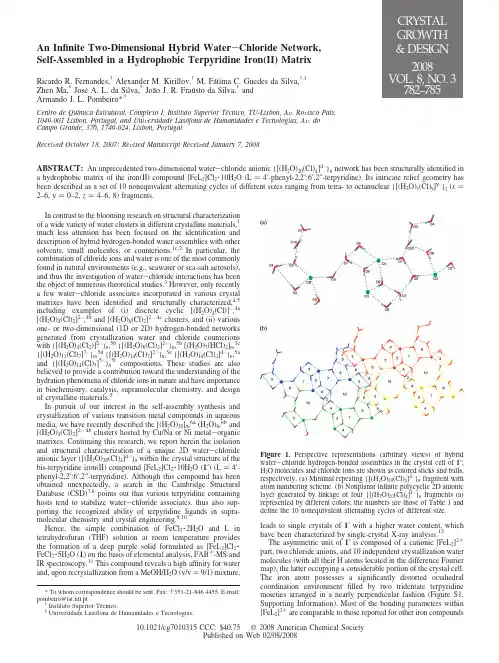
An Infinite Two-Dimensional Hybrid Water-Chloride Network,Self-Assembled in a Hydrophobic Terpyridine Iron(II)MatrixRicardo R.Fernandes,†Alexander M.Kirillov,†M.Fátima C.Guedes da Silva,†,‡Zhen Ma,†JoséA.L.da Silva,†João J.R.Fraústo da Silva,†andArmando J.L.Pombeiro*,†Centro de Química Estrutural,Complexo I,Instituto Superior Técnico,TU-Lisbon,A V.Ro V isco Pais,1049-001Lisbon,Portugal,and Uni V ersidade Luso´fona de Humanidades e Tecnologias,A V.doCampo Grande,376,1749-024,Lisbon,PortugalRecei V ed October18,2007;Re V ised Manuscript Recei V ed January7,2008ABSTRACT:An unprecedented two-dimensional water-chloride anionic{[(H2O)20(Cl)4]4–}n network has been structurally identified in a hydrophobic matrix of the iron(II)compound[FeL2]Cl2·10H2O(L)4′-phenyl-2,2′:6′,2″-terpyridine).Its intricate relief geometry has been described as a set of10nonequivalent alternating cycles of different sizes ranging from tetra-to octanuclear{[(H2O)x(Cl)y]y–}z(x) 2–6,y)0–2,z)4–6,8)fragments.In contrast to the blooming research on structural characterizationof a wide variety of water clusters in different crystalline materials,1much less attention has been focused on the identification anddescription of hybrid hydrogen-bonded water assemblies with othersolvents,small molecules,or counterions.1c,2In particular,thecombination of chloride ions and water is one of the most commonlyfound in natural environments(e.g.,seawater or sea-salt aerosols),and thus the investigation of water-chloride interactions has beenthe object of numerous theoretical studies.3However,only recentlya few water-chloride associates incorporated in various crystalmatrixes have been identified and structurally characterized,4,5including examples of(i)discrete cyclic[(H2O)4(Cl)]–,4a[(H2O)4(Cl)2]2–,4b and[(H2O)6(Cl)2]2–4c clusters,and(ii)variousone-or two-dimensional(1D or2D)hydrogen-bonded networksgenerated from crystallization water and chloride counterionswith{[(H2O)4(Cl2)]2–}n,5b{[(H2O)6(Cl)2]2–}n,5b[(H2O)7(HCl)2]n,5c{[(H2O)11(Cl)7]7–}n,5d{[(H2O)14(Cl)2]2–}n,5e{[(H2O)14(Cl)4]4–}n,5aand{[(H2O)14(Cl)5]5–}n5f compositions.These studies are alsobelieved to provide a contribution toward the understanding of thehydration phenomena of chloride ions in nature and have importancein biochemistry,catalysis,supramolecular chemistry,and designof crystalline materials.5In pursuit of our interest in the self-assembly synthesis andcrystallization of various transition metal compounds in aqueousmedia,we have recently described the[(H2O)10]n,6a(H2O)6,6b and[(H2O)4(Cl)2]2–4b clusters hosted by Cu/Na or Ni metal-organicmatrixes.Continuing this research,we report herein the isolationand structural characterization of a unique2D water-chlorideanionic layer{[(H2O)20(Cl)4]4–}n within the crystal structure of thebis-terpyridine iron(II)compound[FeL2]Cl2·10H2O(1′)(L)4′-phenyl-2,2′:6′,2″-terpyridine).Although this compound has beenobtained unexpectedly,a search in the Cambridge StructuralDatabase(CSD)7,8points out that various terpyridine containinghosts tend to stabilize water-chloride associates,thus also sup-porting the recognized ability of terpyridine ligands in supra-molecular chemistry and crystal engineering.9,10Hence,the simple combination of FeCl2·2H2O and L in tetrahydrofuran(THF)solution at room temperature provides the formation of a deep purple solid formulated as[FeL2]Cl2·FeCl2·5H2O(1)on the basis of elemental analysis,FAB+-MS and IR spectroscopy.11This compound reveals a high affinity for water and,upon recrystallization from a MeOH/H2O(v/v)9/1)mixture,leads to single crystals of1′with a higher water content,which have been characterized by single-crystal X-ray analysis.12The asymmetric unit of1′is composed of a cationic[FeL2]2+ part,two chloride anions,and10independent crystallization water molecules(with all their H atoms located in the difference Fourier map),the latter occupying a considerable portion of the crystal cell. The iron atom possesses a significantly distorted octahedral coordination environmentfilled by two tridentate terpyridine moieties arranged in a nearly perpendicular fashion(Figure S1, Supporting Information).Most of the bonding parameters within [FeL2]2+are comparable to those reported for other iron compounds*To whom correspondence should be sent.Fax:+351-21-8464455.E-mail: pombeiro@ist.utl.pt.†Instituto Superior Técnico.‡Universidade Luso´fona de Humanidades eTecnologias.Figure 1.Perspective representations(arbitrary views)of hybrid water-chloride hydrogen-bonded assemblies in the crystal cell of1′; H2O molecules and chloride ions are shown as colored sticks and balls, respectively.(a)Minimal repeating{[(H2O)20(Cl)4]4–}n fragment with atom numbering scheme.(b)Nonplanar infinite polycyclic2D anionic layer generated by linkage of four{[(H2O)20(Cl)4]4–}n fragments(a) represented by different colors;the numbers are those of Table1and define the10nonequivalent alternating cycles of different size.2008310.1021/cg7010315CCC:$40.75 2008American Chemical SocietyPublished on Web02/08/2008bearing two terpyridine ligands.13The most interesting feature of the crystal structure of 1′consists in the extensive hydrogen bonding interactions of all the lattice–water molecules and chloride coun-terions (Table S1,Supporting Information),leading to the formation of a hybrid water -chloride polymeric assembly possessing minimal repeating {[(H 2O)20(Cl)4]4–}n fragments (Figure 1a).These are further interlinked by hydrogen bonds generating a nonplanar 2D water -chloride anionic layer (Figure 1b).Hence,the multicyclic {[(H 2O)20(Cl)4]4–}n fragment is con-structed by means of 12nonequivalent O–H ···O interactions with O ···O distances ranging from 2.727to 2.914Åand eight O–H ···Cl hydrogen bonds with O ···Cl separations varying in the 3.178–3.234Årange (Table S1,Supporting Information).Both average O ···O [∼2.82Å]and O ···Cl [∼3.20Å]separations are comparable to those found in liquid water (i.e.,2.85Å)14and various types of H 2O clusters 1,6or hybrid H 2O -Cl associates.4,5Eight of ten water molecules participate in the formation of three hydrogen bonds each (donating two and accepting one hydrogen),while the O3and O7H 2O molecules along with both Cl1and Cl2ions are involved in four hydrogen-bonding contacts.The resulting 2D network can be considered as a set of alternating cyclic fragments (Figure 1b)which are classified in Table 1and additionally shown by different colors in Figure 2.Altogether there are 10different cycles,that is,five tetranuclear,three pentanuclear,one hexanuclear,and one octa-nuclear fragment (Figures 1b and 2,Table 1).Three of them (cycles 1,2,and 6)are composed of only water molecules,whereas the other seven rings are water -chloride hybrids with one or two Cl atoms.The most lengthy O ···O,O ···Cl,or Cl ···Cl nonbonding separations within rings vary from 4.28to 7.91Å(Table 1,cycles 1and 10,respectively).Most of the cycles are nonplanar (except those derived from the three symmetry generated tetrameric fragments,cycles 1,2,and 4),thus contributing to the formation of an intricate relief geometry of the water -chloride layer,possessing average O ···O ···O,O ···Cl ···O,and O ···O ···Cl angles of ca.104.9,105.9,and 114.6°,respectively (Table S2,Supporting Information).The unprecedented character of thewater -chloride assembly in 1′has been confirmed by a thorough search in the CSD,7,15since the manual analysis of 156potentially significant entries with the minimal [(H 2O)3(Cl)]–core obtained within the searching algorithm 15did not match a similar topology.Nevertheless,we were able to find several other interesting examples 16of infinite 2D and three-dimensional (3D)water -chloride networks,most of them exhibiting strong interactions with metal -organic matrixes.The crystal packing diagram of 1′along the a axis (Figure 3)shows that 2D water -chloride anionic layers occupy the free space between hydrophobic arrays of metal -organic units,with an interlayer separation of 12.2125(13)Åthat is equivalent to the b unit cell dimension.12In contrast to most of the previously identified water clusters,1,6water -chloride networks,5,16and extended assemblies,1c the incorporation of {[(H 2O)20(Cl)4]4–}n sheets in 1′is not supported by strong intermolecular interactions with the terpyridine iron matrix.Nevertheless,four weak C–H ···O hydrogen bonds [avg d (D ···A))3.39Å]between some terpyridine CH atoms and lattice–water molecules (Table S1,Figure S2,Supporting Information)lead to the formation of a 3D supramolecular framework.The thermal gravimetric analysis (combined TG-DSC)of 117(Figure S3,Supporting Information)shows the stepwise elimination of lattice–water in the broad 50–305°C temperature interval,in accord with the detection on the differential scanning calorimetryTable 1.Description of Cyclic Fragments within the {[(H 2O)20(Cl)4]4–}n Network in 1′entry/cycle numbernumber of O/Cl atomsformula atom numberingschemegeometry most lengthy separation,Åcolor code a 14(H 2O)4O3–O4–O3–O4planar O3···O3,4.28light brown 24(H 2O)4O6–O7–O6–O7planar O7···O7,4.42light gray 34[(H 2O)3(Cl)]-O2–O4–O3–Cl2nonplanar O4···Cl2,4.66blue 44[(H 2O)3(Cl)]-O6–O7–O9–Cl1nonplanar O7···Cl1,4.61green 54[(H 2O)2(Cl)2]2-O9–Cl1–O9–Cl1planar Cl ···Cl1,4.76pink 65(H 2O)5O2–O4–O3–O10–O8nonplanar O2···O10,4.55red75[(H 2O)4(Cl)]-O1–O5–O7–O9–Cl1nonplanar O7···Cl1,5.25pale yellow 85[(H 2O)4(Cl)]-O1–O5–Cl2–O8–O10nonplanar O10···Cl2,5.29orange 96[(H 2O)4(Cl)2]2-O2–O8–Cl2–O2–O8–Cl2nonplanar Cl2···Cl2,7.12yellow 108[(H 2O)6(Cl)2]2-O1–O10–O3–Cl2–O5–O7–O6–Cl1nonplanarCl1···Cl2,7.91pale blueaColor codes are those of Figure 2.Figure 2.Fragment of nonplanar infinite polycyclic 2D anionic layer in the crystal cell of 1′.The 10nonequivalent alternating water or water -chloride cycles are shown by different colors (see Table 1for color codes).Figure 3.Fragment of the crystal packing diagram of 1′along the a axis showing the intercalation of two water -chloride layers (represented by space filling model)into the metal -organic matrix (depicted as sticks);color codes within H 2O -Cl layers:O red,Cl green,H grey.Communications Crystal Growth &Design,Vol.8,No.3,2008783curve(DSC)of three major endothermic processes in ca.50–170, 170–200,and200–305°C ranges with maxima at ca.165,190, and280°C,corresponding to the stepwise loss of ca.two,one, and two H2O molecules,respectively(the overall mass loss of9.1% is in accord with the calculated value of9.4%for the elimination of allfive water molecules).In accord,the initial broad and intense IRν(H2O)andδ(H2O)bands of1(maxima at3462and1656cm–1, respectively)gradually decrease in intensity on heating the sample up to ca.305°C,while the other bands remain almost unchangeable. Further heating above305°C leads to the sequential decomposition of the bis-terpyridine iron unit.These observations have also been supported by the IR spectra of the products remaining after heating the sample at different temperatures.The elimination of the last portions of water in1at temperatures as high as250–305°C is not commonly observed(although it is not unprecedented18)for crystalline materials with hosted water clusters,and can be related to the presence and extensive hydrogen-bonding of chloride ions in the crystal cell,tending to form the O–H(water)···Cl hydrogen bonds ca.2.5times stronger in energy than the corresponding O–H(water)···O(water)ones.5a The strong binding of crystallization water in1is also confirmed by its FAB+-MS analysis that reveals the rather uncommon formation of the fragments bearing from one tofive H2O molecules.11The exposure to water vapors for ca.8h of an almost completely dehydrated(as confirmed by weighing and IR spectroscopy)product after thermolysis of1(at250°C19for 30min)results in the reabsorption of water molecules giving a material with weight and IR spectrum identical to those of the initial sample1,thus corroborating the reversibility of the water escape and binding process.In conclusion,we have synthesized and structurally characterized a new type of2D hybrid water-chloride anionic multicyclic {[(H2O)20(Cl)4]4–}n network self-assembled in a hydrophobic matrix of the bis-terpyridine iron(II)complex,that is,[FeL2]Cl2·10H2O 1′.On the basis of the recent description and detailed analysis of the related{[(H2O)14(Cl)4]4–}n layers5a and taking into consideration that the water-chloride assembly in1′does not possess strong interactions with the metal-organic units,the crystal structure of 1′can alternatively be defined as an unusual set of water-chloride “hosts”with bis-terpyridine iron“guests”.Moreover,the present study extends the still limited number5of well-identified examples of large polymeric2D water-chloride assemblies intercalated in crystalline materials and shows that terpyridine compounds can provide rather suitable matrixes to stabilize and store water-chloride aggregates.Further work is currently in progress aiming at searching for possible applications in nanoelectrical devices,as well as understanding how the modification of the terpyridine ligand or the replacement of chlorides by other counterions with a high accepting ability toward hydrogen-bonds can affect the type and topology of the hybrid water containing associates within various terpyridine transition metal complexes.Acknowledgment.This work has been partially supported by the Foundation for Science and Technology(FCT)and its POCI 2010programme(FEDER funded),and by a HRTM Marie Curie Research Training Network(AQUACHEM project,CMTN-CT-2003-503864).The authors gratefully acknowledge Prof.Maria Filipa Ribeiro for kindly running the TG-DSC analysis,urent Benisvy,Dr.Maximilian N.Kopylovich,and Mr.Yauhen Y. Karabach for helpful discussions.Supporting Information Available:Additionalfigures(Figures S1–S3)with structural fragments of1′and TG-DSC analysis of1, Tables S1and S2with hydrogen-bond geometry in1′and bond angles within the H2O-Cl network,details for the general experimental procedures and X-ray crystal structure analysis and refinement,crystal-lographic informationfile(CIF),and the CSD refcodes for terpyridine compounds with water-chloride aggregates.This information is available free of charge via the Internet at .References(1)(a)Mascal,M.;Infantes,L.;Chisholm,J.Angew.Chem.,Int.Ed.2006,45,32and references therein.(b)Infantes,L.;Motherwell,S.CrystEngComm2002,4,454.(c)Infantes,L.;Chisholm,J.;Mother-well,S.CrystEngComm2003,5,480.(d)Supriya,S.;Das,S.K.J.Cluster Sci.2003,14,337.(2)(a)Das,M.C.;Bharadwaj,P.K.Eur.J.Inorg.Chem.2007,1229.(b)Ravikumar,I.;Lakshminarayanan,P.S.;Suresh,E.;Ghosh,P.Cryst.Growth Des.2006,6,2630.(c)Ren,P.;Ding,B.;Shi,W.;Wang,Y.;Lu,T.B.;Cheng,P.Inorg.Chim.Acta2006,359,3824.(d)Li,Z.G.;Xu,J.W.;Via,H.Q.;Hu,mun.2006,9,969.(e)Lakshminarayanan,P.S.;Kumar,D.K.;Ghosh,P.Inorg.Chem.2005,44,7540.(f)Raghuraman,K.;Katti,K.K.;Barbour,L.J.;Pillarsetty,N.;Barnes,C.L.;Katti,K.V.J.Am.Chem.Soc.2003,125,6955.(3)(a)Jungwirth,P.;Tobias,D.J.J.Phys.Chem.B.2002,106,6361.(b)Tobias,D.J.;Jungwirth,P.;Parrinello,M.J.Chem.Phys.2001,114,7036.(c)Choi,J.H.;Kuwata,K.T.;Cao,Y.B.;Okumura,M.J.Phys.Chem.A.1998,102,503.(d)Xantheas,S.S.J.Phys.Chem.1996,100,9703.(e)Markovich,G.;Pollack,S.;Giniger,R.;Cheshnovsky,O.J.Chem.Phys.1994,101,9344.(f)Combariza,J.E.;Kestner,N.R.;Jortner,J.J.Chem.Phys.1994,100,2851.(g)Perera, L.;Berkowitz,M.L.J.Chem.Phys.1991,95,1954.(h)Dang,L.X.;Rice,J.E.;Caldwell,J.;Kollman,P.A.J.Am.Chem.Soc.1991, 113,2481.(4)(a)Custelcean,R.;Gorbunova,M.G.J.Am.Chem.Soc.2005,127,16362.(b)Kopylovich,M.N.;Tronova,E.A.;Haukka,M.;Kirillov,A.M.;Kukushkin,V.Yu.;Fraústo da Silva,J.J.R.;Pombeiro,A.J.L.Eur.J.Inorg.Chem.2007,4621.(c)Butchard,J.R.;Curnow,O.J.;Garrett,D.J.;Maclagan,R.G.A.R.Angew.Chem.,Int.Ed.2006, 45,7550.(5)(a)Reger,D.L.;Semeniuc,R.F.;Pettinari,C.;Luna-Giles,F.;Smith,M.D.Cryst.Growth.Des.2006,6,1068and references therein.(b) Saha,M.K.;Bernal,mun.2005,8,871.(c) Prabhakar,M.;Zacharias,P.S.;Das,mun.2006,9,899.(d)Lakshminarayanan,P.S.;Suresh,E.;Ghosh,P.Angew.Chem.,Int.Ed.2006,45,3807.(e)Ghosh,A.K.;Ghoshal,D.;Ribas,J.;Mostafa,G.;Chaudhuri,N.R.Cryst.Growth.Des.2006,6,36.(f)Deshpande,M.S.;Kumbhar,A.S.;Puranik,V.G.;Selvaraj, K.Cryst.Growth Des.2006,6,743.(6)(a)Karabach,Y.Y.;Kirillov,A.M.;da Silva,M.F.C.G.;Kopylovich,M.N.;Pombeiro,A.J.L.Cryst.Growth Des.2006,6,2200.(b) Kirillova,M.V.;Kirillov,A.M.;da Silva,M.F.C.G.;Kopylovich, M.N.;Fraústo da Silva,J.J.R.;Pombeiro,A.J.L.Inorg.Chim.Acta2008,doi:10.1016/j.ica.2006.12.016.(7)The Cambridge Structural Database(CSD).Allen, F.H.ActaCrystallogr.2002,B58,380.(8)The searching algorithm in the ConQuest Version1.9(CSD version5.28,August2007)constrained to the presence of any terpyridinemoiety and at least one crystallization water molecule and one chloride counter ion resulted in43analyzable hits from which40compounds contain diverse water-chloride aggregates(there are29and11 examples of infinite(mostly1D)networks and discrete clusters, respectively).See the Supporting Information for the CSD refcodes.(9)For a recent review,see Constable,E.C.Chem.Soc.Re V.2007,36,246.(10)For recent examples of supramolecular terpyridine compounds,see(a)Beves,J.E.;Constable,E.C.;Housecroft,C.E.;Kepert,C.J.;Price,D.J.CrystEngComm2007,9,456.(b)Zhou,X.-P.;Ni,W.-X.;Zhan,S.-Z.;Ni,J.;Li,D.;Yin,Y.-G.Inorg.Chem.2007,46,2345.(c)Shi,W.-J.;Hou,L.;Li,D.;Yin,Y.-G.Inorg.Chim.Acta2007,360,588.(d)Beves,J.E.;Constable,E.C.;Housecroft,C.E.;Kepert,C.J.;Neuburger,M.;Price,D.J.;Schaffner,S.CrystEngComm2007,9,1073.(e)Beves,J. E.;Constable, E. C.;Housecroft, C. E.;Neuburger,M.;Schaffner,mun.2007,10,1185.(f)Beves,J.E.;Constable,E.C.;Housecroft,C.E.;Kepert,C.J.;Price,D.J.CrystEngComm2007,9,353.(11)Synthesis of1:FeCl2·2H2O(82mg,0.50mmol)and4′-phenyl-2,2′:6′,2″-terpyridine(L)(154mg,0.50mmol)were combined in a THF (20mL)solution with continuous stirring at room temperature.The resulting deep purple suspension was stirred for1h,filtered off,washed with THF(3×15mL),and dried in vacuo to afford a deep purple solid1(196mg,41%).1exhibits a high affinity for water and upon recrystallization gives derivatives with a higher varying content of crystallization water.1is soluble in H2O,MeOH,EtOH,MeCN, CH2Cl2,and CHCl3.mp>305°C(dec.).Elemental analysis.Found: C52.96,H3.76,N8.36.Calcld.for C42H40Cl4Fe2N6O5:C52.42,H4.19,N8.73.FAB+-MS:m/z:835{[FeL2]Cl2·5H2O+H}+,816784Crystal Growth&Design,Vol.8,No.3,2008Communications{[FeL2]Cl2·4H2O}+,796{[FeL2]Cl2·3H2O–2H}+,781{[FeL2]Cl2·2H2O+H}+,763{[FeL2]Cl2·H2O+H}+,709{[FeL2]Cl}+,674 {[FeL2]}+,435{[FeL]Cl2}+,400{[FeL]Cl}+,364{[FeL]–H}+,311 {L–2H}+.IR(KBr):νmax/cm–1:3462(m br)ν(H2O),3060(w),2968 (w)and2859(w)ν(CH),1656(m br)δ(H2O),1611(s),1538(w), 1466(m),1416(s),1243(m),1159(w),1058(m),877(s),792(s), 766(vs),896(m),655(w),506(m)and461(m)(other bands).The X-ray quality crystals of[FeL2]Cl2·10H2O(1′)were grown by slow evaporation,in air at ca.20°C,of a MeOH/H2O(v/v)9/1)solution of1.(12)Crystal data:1′:C42H50Cl2FeN6O10,M)925.63,triclinic,a)10.1851(10),b)12.2125(13),c)19.5622(19)Å,R)76.602(6),)87.890(7),γ)67.321(6)°,U)2180.3(4)Å3,T)150(2)K,space group P1j,Z)2,µ(Mo-K R))0.532mm-1,32310reflections measured,8363unique(R int)0.0719)which were used in all calculations,R1)0.0469,wR2)0.0952,R1)0.0943,wR2)0.1121 (all data).(13)(a)McMurtrie,J.;Dance,I.CrystEngComm2005,7,230.(b)Nakayama,Y.;Baba,Y.;Yasuda,H.;Kawakita,K.;Ueyama,N.Macromolecules2003,36,7953.(c)Kabir,M.K.;Tobita,H.;Matsuo,H.;Nagayoshi,K.;Yamada,K.;Adachi,K.;Sugiyama,Y.;Kitagawa,S.;Kawata,S.Cryst.Growth Des.2003,3,791.(14)Ludwig,R.Angew.Chem.,Int.Ed.2001,40,1808.(15)The searching algorithm in the ConQuest Version1.9(CSD version5.28,May2007)was constrained to the presence of(i)at least onetetranuclear[(H2O)3(Cl)]–ring(i.e.,minimal cyclic fragment in our water-chloride network)with d(O···O))2.2–3.2Åand d(O···Cl) )2.6–3.6Å,and(ii)at least one crystallization water molecule andone chloride counter ion.All symmetry-related contacts were taken into consideration.(16)For2D networks with the[(H2O)3(Cl)]–core,see the CSD refcodes:AGETAH,AMIJAH,BEXVIJ,EXOWIX,FANJUA,GAFGIE, HIQCIT,LUNHUX,LUQCEF,PAYBEW,TESDEB,TXCDNA, WAQREL,WIXVUU,ZUHCOW.For3D network,see the CSD refcode:LUKZEW.(17)This analysis was run on1since we were unable to get1′in a sufficientamount due to the varying content of crystallization water in the samples obtained upon recrystallization of1.(18)(a)Das,S.;Bhardwaj,P.K.Cryst.Growth.Des.2006,6,187.(b)Wang,J.;Zheng,L.-L.;Li,C.-J.;Zheng,Y.-Z.;Tong,M.-L.Cryst.Growth.Des.2006,6,357.(c)Ghosh,S.K.;Ribas,J.;El Fallah, M.S.;Bharadwaj,P.K.Inorg.Chem.2005,44,3856.(19)A temperature below305°C has been used to avoid the eventualdecomposition of the compound upon rather prolonged heating.CG7010315Communications Crystal Growth&Design,Vol.8,No.3,2008785。
DOI: 10.1126/science.1220854, 773 (2013);339 Science et al.Marc André Meyers ConnectionsStructural Biological Materials: Critical Mechanics-MaterialsThis copy is for your personal, non-commercial use only.clicking here.colleagues, clients, or customers by , you can order high-quality copies for your If you wish to distribute this article to othershere.following the guidelines can be obtained by Permission to republish or repurpose articles or portions of articles): May 1, 2013 (this information is current as of The following resources related to this article are available online at/content/339/6121/773.full.html version of this article at:including high-resolution figures, can be found in the online Updated information and services, /content/339/6121/773.full.html#ref-list-1, 12 of which can be accessed free:cites 51 articles This article/cgi/collection/mat_sci Materials Sciencesubject collections:This article appears in the following registered trademark of AAAS.is a Science 2013 by the American Association for the Advancement of Science; all rights reserved. The title Copyright American Association for the Advancement of Science, 1200 New York Avenue NW, Washington, DC 20005. (print ISSN 0036-8075; online ISSN 1095-9203) is published weekly, except the last week in December, by the Science o n M a y 1, 2013w w w .s c i e n c e m a g .o r g D o w n l o a d e d f r o mStructural BiologicalMaterials:CriticalMechanics-Materials ConnectionsMarc AndréMeyers,1,2*Joanna McKittrick,1Po-Yu Chen3Spider silk is extraordinarily strong,mollusk shells and bone are tough,and porcupine quills and feathers resist buckling.How are these notable properties achieved?The building blocks of the materials listed above are primarily minerals and biopolymers,mostly in combination;the first weak in tension and the second weak in compression.The intricate and ingenious hierarchical structures are responsible for the outstanding performance of each material.Toughness is conferred by the presence of controlled interfacial features(friction,hydrogen bonds,chain straightening and stretching);buckling resistance can be achieved by filling a slender column with a lightweight foam.Here,we present and interpret selected examples of these and other biological materials.Structural bio-inspired materials design makes use of the biological structures by inserting synthetic materials and processes that augment the structures’capability while retaining their essential features.In this Review,we explain this idea through some unusual concepts.M aterials science is a vibrant field of in-tellectual endeavor and research.Thisfield applies physics and chemistry, melding them in the process,to the interrela-tionship between structure,properties,and perform-ance of complex materials with technological applications.Thus,materials science extends these rigorous scientific disciplines into complex ma-terials that have structures providing properties and synergies beyond those of pure and simple solids.Initially geared at synthetic materials,ma-terials science has recently extended its reach into biology,especially into the extracellular matrix, whose mechanical properties are of utmost im-portance in living organisms.Some of the semi-nal work and important contributions in this field are either presented or reviewed in(1–5).There are a number of interrelated features that define biological materials and distinguish them from their synthetic counterparts[inspired by Arzt(6)]: (i)Self-assembly.In contrast to many synthetic processes to produce materials,the structures are assembled from the bottom up,rather than from the top down.(ii)Multi-functionality.Many com-ponents serve more than one purpose.For exam-ple,feathers provide flight capability,camouflage, and insulation,whereas bones provide structural framework,promote the growth of red blood cells, and provide protection to the internal organs.(iii) Hierarchy.Different,organized scale levels(nano-to ultrascale)confer distinct and translatable prop-erties from one level to the next.We are starting to develop a systematic and quantitative understandingof this hierarchy by distinguishing the character-istic levels,developing constitutive descriptionsof each level,and linking them through appro-priate and physically based equations,enabling afull predictive understanding.(iv)Hydration.Theproperties are highly dependent on the level ofwater in the structure.There are some exceptions,such as enamel,but this rule applies to mostbiological materials and is of importance to me-chanical properties such as strength(which isdecreased by hydration)and toughness(which isincreased).(v)Mild synthesis conditions.Themajority of biological materials are fabricated atambient temperature and pressure as well as in anaqueous environment,a notable difference fromsynthetic materials fabrication.(vi)Evolution andenvironmental constraints.The limited availabil-ity of useful elements dictates the morphologyand resultant properties.The structures are notnecessarily optimized for all properties but arethe result of an evolutionary process leading tosatisfactory and robust solutions.(vii)Self-healingcapability.Whereas synthetic materials undergodamage and failure in an irreversible manner,biological materials often have the capability,due to the vascularity and cells embedded in thestructure,to reverse the effects of damage byhealing.The seven characteristics listed above arepresent in a vast number of structures.Nevertheless,the structures of biological materials can bedivided into two broad classes:(i)non-mineralized(“soft”)structures,which are composed of fibrousconstituents(collagen,keratin,elastin,chitin,lignin,and other biopolymers)that display widelyvarying mechanical properties and anisotropiesdepending on the function,and(ii)mineralized(“hard”)structures,consisting of hierarchicallyassembled composites of minerals(mainly,butnot solely,hydroxyapatite,calcium carbonate,and amorphous silica)and organic fibrous com-ponents(primarily collagen and chitin).The mechanical behavior of biological con-stituents and composites is quite diverse.Bio-minerals exhibit linear elastic stress-strain plots,whereas the biopolymer constituents are non-linear,demonstrating either a J shape or a curvewith an inflection point.Foams are characterizedby a compressive response containing a plastic orcrushing plateau in which the porosity is elim-inated.Many biological materials are compositeswith many components that are hierarchicallystructured and can have a broad variety of con-stitutive responses.Below,we present some of thestructures and functionalities of biological ma-terials with examples from current research.Here,we focus on three points:(i)How high tensilestrength is achieved(biopolymers),(ii)how hightoughness is attained(composite structures),and(iii)how bending resistance is achieved in light-weight structures(shells with an interior foam).Structures in Tension:Importance of BiopolymersThe ability to sustain tensile forces requires aspecific set of molecular and configurational con-formations.The initial work performed on exten-sion should be small,to reduce energy expenditure,whereas the material should stiffen close to thebreaking point,to resist failure.Thus,biopolymers,such as collagen and viscid(catching spiral)spidersilk,have a J-shaped stress-strain curve where mo-lecular uncoiling and unkinking occur with con-siderable deformation under low stress.This stiffening as the chains unfurl,straighten,stretch,and slide past each other can be repre-sented analytically in one,two,and three dimen-sions.Examples are constitutive equations initiallydeveloped for polymers by Ogden(7)and Arrudaand Boyce(8).An equation specifically proposedfor tissues is given by Fung(3).A simpler for-mulation is given here;the slope of the stress-strain(s-e)curve increases monotonically with strain.Thus,one considers two regimes:(i)unfurlingand straightening of polymer chainsd sd eºe nðn>1Þð1Þand(ii)stretching of the polymer chain backbonesd sd eºEð2Þwhere E is the elastic modulus of the chains.Thecombined equation,after integrating Eqs.1and2,iss=k1e n+1+H(e c)E(e–e c)(3)Here k1is a parameter,and H is the Heavisidefunction,which activates the second term at e=e c,where e c is a characteristic strain at whichcollagen fibers are fully extended.Subsequent straingradually becomes dominated by chain stretch-ing.The computational results by Gautieri et al.(9)on collagen fibrils corroborate Eq.3for n=1.This corresponds to a quadratic relation between1Department of Mechanical and Aerospace Engineering andMaterials Science and Engineering Program,University ofCalifornia,San Diego,La Jolla,CA92093,USA.2Department ofNanoengineering,University of California,San Diego,La Jolla,CA92093,USA.3Department of Materials Science and En-gineering,National Tsing Hua University,Hsinchu30013,Taiwan,Republic of China.*To whom correspondence should be addressed.E-mail:mameyers@ SCIENCE VOL33915FEBRUARY2013773o n M a y 1 , 2 0 1 3 w w w . s c i e n c e m a g . o r g D o w n l o a d e d f r o mstress and strain (s ºe 2),which has the char-acteristic J shape.Collagen is the most important structural bio-logical polymer,as it is the key component in many tissues (tendon,ligaments,skin,and bone),as well as in the extracellular matrix.The de-formation process is intimately connected to the different hierarchical levels,starting with the poly-peptides (0.5-nm diameter)to the tropocollagen molecules (1.5-nm diameter),then to the fibrils (~40-to 100-nm diameter),and finally to fibers (~1-to 10-m m diameter)and fascicles (>10-m m diameter).Molecular dynamics computations (9)of entire fibrils show the J -curve response;these computational predictions are well matched to atomic force microscopy (AFM)(10),small-angle x-ray scattering (SAXS)(11),and experiments by Fratzl et al .(12),as shown in Fig.1A.The effect of hydration is also seen and is of great impor-tance.The calculated density of collagen de-creases from 1.34to 1.19g/cm 3with hydration and is accompanied by a decrease in the Young ’s modulus from 3.26to 0.6GPa.The response of silk and spider thread is fascinating.As one of the toughest known ma-terials,silk also has high tensile strength and extensibility.It is composed of b sheet (10to 15volume %)nanocrystals [which consist of highly conserved poly-(Gly-Ala)and poly-Ala domains]embedded in a disordered matrix (13).Figure 1B shows the J -shape stress-strain curve and molecular configurations for the crystalline domains in silkworm (Bombyx mori )silk (14).Similar to collagen,the low-stress region corre-sponds to uncoiling and straightening of the pro-tein strands.This region is followed by entropic unfolding of the amorphous strands and then stiffening due to load transfer to the crystalline b sheets.Despite the high strength,the major mo-lecular interactions in the b sheets are weak hy-drogen bonds.Molecular dynamics simulations,Fig.1.Tensile stress-strain relationships in bio-polymers.(A )J -shaped curve for hydrated and dry collagen fibrils obtained from molecular dynamics (MD)simulations and AFM and SAXS studies.At low stress levels,considerable stretching occurs due to the uncrimping and unfolding of molecules;at higher stress levels,the polymer backbone stretches.Adapted from (9,12).(B )Stretching of dragline spider silk and molecular schematic of the protein fibroin.At low stress levels,entropic effects domi-nate (straightening of amorphous strands);at higher levels,the crystalline parts sustain the load.(C )Mo-lecular dynamics simulation of silk:(i)short stack and (ii)long stack of b -sheet crystals,showing that a higher pullout force is required in the short stack;for the long stack,bending stresses become im-portant.Hydrogen bonds connect b -sheet crystals.Adapted from (14).(D )Egg whelk case (bioelastomer)showing three regions:straightening of the a helices,the a helix –to –b sheet transformation,and b -sheet extension.A molecular schematic is shown.Adapted from (18).300.000.2Yield pointEntropic unfoldingMD simulationsStick slipStiffening β-crystal123456700012345670102030405050010001500200025050075010001250150017500.40.60.80.010.020.030.040.05MD wet (Gautieri et al)SAXS (Sasaki and Odajima)AFM (Aladin et al)MD dry (Gautieri et al)2520151050S t r e s s (M P a )S t r e s s(M P a )StrainABCDStrain (m/m)Length (nm)Length (nm)Stick-slip deformation (robust)"brittle" fracture (fragile)i iiP u l l -o u t f o r c e (p N )00.20.4Native state Unloading: reformation of α-helicesDomain 4: Extension andalignmentof β-sheets0.60.8ε=0ε4ε=01.0012345StrainS t r e s s (M P a )E n e r g y /v o l u m e (k c a l /m o l /n m 3)L e n g t hI I II II III IIIIVIVFDomain 3: Formation of β-sheetsfrom random coilsε3Domain 2: Extension of random coilsε2Domain 1: Unraveling of α-helicesinto random coilsε1Toughness (MD)Resilience (MD)T=-1°C T=20°C T=40°C T=60°C T=80°C15FEBRUARY 2013VOL 339SCIENCE 774REVIEWo n M a y 1, 2013w w w .s c i e n c e m a g .o r g D o w n l o a d e d f r o mshown in Fig.1C,illustrate an energy dissipative stick-slip shearing of the hydrogen bonds during failure of the b sheets (14).For a stack with a height L ≤3nm (left-hand side of Fig.1C),the shear stresses are more substantial than the flex-ure stresses,and the hydrogen bonds contribute to the high strength obtained (1.5GPa).How-ever,if the stack of b sheets is too high (right-hand side of Fig.1C),it undergoes bending with tensile separation between adjacent sheets.The nanoscale dimension of the b sheets allows for a ductile instead of brittle failure,resulting in high toughness values of silk.Thus,size affects the mechanical response considerably,changing the deformation characteristics of the weak hydro-gen bonds.This has also been demonstrated in bone (15–17),where sacrificial hydrogen bonds between mineralized collagen fibrils contribute to the excellent fracture resistance.Other biological soft materials have more complex responses,marked by discontinuities in d s /d e .This is the case for wool,whelk eggs,silks,and spider webs.Several mechanisms are responsible for this change in slope;for instance,the transition from a -to b -keratin,entropic changes with strain (such as those prevalent in rubber,where chain stretching and alignment decrease entropy),and others.The example of egg whelk is shown in Fig.1D (18).In this case,there is a specific stress at which a -keratin heli-ces transform to b sheets,with an associated change in length.Upon unloading,the reverse occurs,and the total reversible strain is,therefore,extensive.This stress-induced phase transforma-tion is similar to what occurs in shape-memory alloys.Thus,this material can experience sub-stantial reversible deformation (up to 80%)in a reversible fashion,when the stress is raised from 2to 5MPa,ensuring the survival of whelk eggs,which are continually swept by waves.These examples demonstrate the distinct properties of biopolymers that allow these ma-terials to be strong and highly extensible with distinctive molecular deformation characteristics.However,many interesting biological materials are composites of flexible biopolymers and stiff minerals.The combination of these two constit-uents leads to the creation of a tough material.Imparting Toughness:Importance of Interfaces One hallmark property of most biological com-posites is that they are tough.Toughness is defined as the amount of energy a material ab-sorbs before it fails,expressed asU ¼∫e fs d eð4Þwhere U is the energy per volume absorbed,s is the stress,e is the strain,and e f is the failure strain.Tough materials show considerable plastic deformation (or permanent damage)coupled with considerable strength.This maximizes the integral expression in Eq.4.Biological com-posite materials (for example,crystalline and noncrystalline components)have a plethora oftoughening mechanisms,many of which depend on the presence of interfaces.As a crack im-pinges on an interface or discontinuity in the material,the crack can be deflected around the interface (requiring more energy to propagate than a straight crack)or can drive through it.The strength of biopolymer fibers in tension im-pedes crack opening;bridges between micro-cracks are another mechanism.The toughening mechanisms have been divided into intrinsic (ex-isting in the material ahead of crack)and extrinsic (generated during the progression of failure)cat-egories (19).Thus,toughening is accomplished by a wide variety of stratagems.We illustrate this concept for four biological materials,shown in Fig.2.All inorganic materials contain flaws and cracks,which reduce the strength from the theo-retical value (~E /10to E /30).The maximum stress (s max )a material can sustain when a preexisting crack of length a is present is given by the Griffith equations max ¼ffiffiffiffiffiffiffiffiffiffi2g s E p a r ¼YK Icffiffiffiffiffip ap ð5Þwhere E is the Young ’s modulus,g s is the sur-face (or damage)energy,and Y is a geometric parameter.K Ic ¼Y −1ffiffiffiffiffiffiffiffiffiffi2g s E p is the fracture toughness,a materials property that expresses the ability to resist crack propagation.Abalone (Haliotis rufescens )nacre has a fracture tough-ness that is vastly superior to that of its major constituent,monolithic calcium carbonate,due to an ordered assembly consisting of mineral tiles with an approximate thickness of 0.5m m and a diameter of ~10m m (Fig.2A).Additionally,this material contains organic mesolayers (separated by ~300m m)that are thought to be seasonal growth bands.The tiles are connected by mineral bridges with ~50-nm diameter and are separated by organic layers,consisting of a chitin network and acidic proteins,which,when combined,have a similar thickness to the mineral bridge diame-ters.The Griffith fracture criterion (Eq.5)can be applied to predict the flaw size (a cr )at which the theoretical strength s th is achieved.With typical values for the fracture toughness (K Ic ),s th ,and E ,the critical flaw size is in the range of tens of nanometers.This led Gao et al .(20)to propose that at sufficiently small dimensions (less than the critical flaw size),materials become insensitive to flaws,and the theoretical strength (~E /30)should be achieved at the nanoscale.However,the strength of the material will be determined by fracture mechanisms operating at all hierar-chical levels.The central micrograph in Fig.2A shows how failure occurs by tile pullout.The interdigitated structure deflects cracks around the tiles instead of through them,thereby increasing the total length of the crack and the energy needed to fracture (increasing the toughness).Thus,we must de-termine how effectively the tiles resist pullout.Three contributions have been identified and are believed to operate synergistically (21).First,themineral bridges are thought to approach thetheoretical strength (10GPa),thereby strongly attaching the tiles together (22).Second,the tile surfaces have asperities that are produced during growth (23)and could produce frictional resist-ance and strain hardening (24).Third,energy is required for viscoelastic deformation (stretching and shearing)of the organic layer (25).One important aspect on the mechanical prop-erties is the effect of alignment of the mineral crystals.The oriented tiles in nacre result in an-isotropic properties with the strength and modulus higher in the longitudinal (parallel to the organic layers)than in the transverse direction.For a composite with a dispersed mineral m of volume fraction V m embedded in a biopolymer (bp)matrix that has a much lower strength and Young ’s modulus than the mineral,the ratio of the lon-gitudinal (L)and transverse (T)properties P (such as elastic modulus)can be expressed,in simpli-fied form,asP L P T ¼P mP bpV m ð1−V m Þð6ÞThus,the longitudinal properties are much higher than the transverse properties.This aniso-tropic response is also observed in other oriented mineralized materials,such as bone and teeth.Another tough biological material is the exo-skeleton of an arthropod.In the case of marine animals [for instance,lobsters (26,27)and crabs (28)],the exoskeleton structure consists of layers of mineralized chitin in a Bouligand arrange-ment (successive layers at the same angle to each other,resulting in a helicoidal stacking sequence and in-plane isotropy).These layers can be en-visaged as being stitched together with ductile tubules that also perform other functions,such as fluid transport and moisture regulation.The cross-ply Bouligand arrangement is effective in crack stopping;the crack cannot follow a straight path,thereby increasing the materials ’toughness.Upon being stressed,the mineral components frac-ture,but the chitin fibers can absorb the strain.Thus,the fractured region does not undergo physical separation with dispersal of fragments,and self-healing can take place (29).Figure 2B shows the structure of the lobster (Homarus americanus )exoskeleton with the Bouligand ar-rangement of the fibers.Bone is another example of a biological ma-terial that demonstrates high toughness.Skeletal mammalian bone is a composite of hydroxyapatite-type minerals,collagen and water.On a volu-metric basis,bone consists of ~33to 43volume %minerals,32to 44volume %organics,and 15to 25volume %water.The Young ’s modulus and strength increase,but the toughness decreases with increasing mineral volume fraction (30).Cortical (dense)mammalian bone has blood ves-sels extending along the long axis of the limbs.In animals larger than rats,the vessel is encased in a circumferentially laminated structure called the osteon.Primary osteons are surrounded by hypermineralized regions,whereas secondary SCIENCEVOL 33915FEBRUARY 2013775REVIEWo n M a y 1, 2013w w w .s c i e n c e m a g .o r g D o w n l o a d e d f r o m(remodeled)osteons are surrounded by a cement line (also of high mineral content)(31).In mam-malian cortical bone,the following intrinsic toughening mechanisms have been identified:molecular uncoiling and intermolecular sliding of collagen,fibrillar sliding of collagen bonds,and microcracking of the mineral matrix (19).Extrinsic mechanisms are collagen fibril bridging,uncracked ligament bridging,and crack deflec-tion and twisting (19).Rarely does a limb bone snap in two with smooth fracture surfaces;the crack is often deflected orthogonal to the crack front direction.In the case of (rehydrated)elk (Cervus elaphus )antler bone (shown in Fig.2C)(32),which has the highest toughness of any bone type by far (33),the hypermineralized re-gions around the primary osteons lead to crackdeflection,and the high amount of collagen (~60volume %)adds mechanisms of crack re-tardation and creates crack bridges behind the crack front.The toughening effect in antlers has been estimated as:crack deflection,60%;un-cracked ligament bridges,35%;and collagen as well as fibril bridging,5%(33).A particu-larly important feature in bone is that the fracture toughness increases as the crack propagates,as shown in the plot.This plot demonstrates the crack extension resistance curve,or R -curve,behavior,which is the rate of the total energy dissipated as a function of the crack size.This occurs by the activation of the extrinsic tough-ening mechanisms.In this manner,it becomes gradually more difficult to advance the crack.In human bone,the cracks are deflected and/ortwisted around the cement lines surrounding the secondary osteons and also demonstrate R -curve behavior (34).The final example illustrating how the presence of interfaces is used to retard crack propagation is the glass sea sponge (Euplectella aspergillum ).The entire structure of the V enus ’flower basket is shown in Fig.2D.Biological silica is amorphous and,within the spicules,consists of concentric layers,separated by an organic material,silicatein (35,36).The flexure strength of the spicule notably exceeds (by approximately fivefold)that of monolithic glass (37).The principal reason is the presence of interfaces,which can arrest and/or deflect the crack.Biological materials use ingenious meth-ods to retard the progression of cracks,therebyAbalone shell: NacreMineral bridgesLobsterDeer antlerChitin fibril networkHuman cortical boneMineral crystallitesPrimary osteonsSubvelvet/compact Subvelvet/cCompact Comp p actTransition zoneCancellousCollagen fibrilsDeep sea spongeSkeletonSpicules20 mm1 cmHuman cortical boneElk antlerTransverseIn-plane longitudinalASTM validASTM invalid Mesolayers ABCD0.1 mm500 nm500 nm ˜1 nm˜3 nm˜20 nmCrack extension, ⌬a (mm)T o u g h n e s s , J (k J m -2)50 nm200 nm 10 m500 nm2 m1 m200 m300 m˜10 m0.010.11101000.20.40.6500 00 nm50 nmFig.2.Hierarchical structures of tough biological materials demonstrating the heterogeneous interfaces that provide crack deflection.(A )Abalone nacre showing growth layers (mesolayers),mineral bridges between mineral tiles and asperities on the surface,the fibrous chitin network that forms the backbone of the inorganic layer,and an example of crack tortuosity in which the crack must travel around the tiles instead of through them [adapted from (4,21)].(B )Lobster exoskeleton showing the twisted plywood structure of the chitin (next to the shell)and the tubules that extend from the chitin layers to the animal [adapted from (27)].(C )Antler bone image showing the hard outer sheath (cortical bone)surrounding the porous bone.The collagen fibrils are highly aligned in the growth direction,with nanocrystalline minerals dispersed in and around them.The osteonal structure in a cross section of cortical bone illustrates the boundaries where cracks perpendicular to the osteons can be directed [adapted from (33)].ASTM,American Society for Testing and Mate-rials.(D )Silica sponge and the intricate scaffold of spicules.Each spicule is a circumferentially layered rod:The interfaces between the layers assist in ar-resting crack anic silicate in bridging adjacent silica layers is observed at higher magnification (red arrow)(36).15FEBRUARY 2013VOL 339SCIENCE776REVIEWo n M a y 1, 2013w w w .s c i e n c e m a g .o r g D o w n l o a d e d f r o mincreasing toughness.These methods operate at levels ranging from the nanoscale to the structur-al scale and involve interfaces to deflect cracks,bridging by ductile phases (e.g.,collagen or chitin),microcracks forming ahead of the crack,delocal-ization of damage,and others.Lightweight Structures Resistant to Bending,Torsion,and Buckling —Shells and FoamsResistance to flexural and torsional tractions with a prescribed deflection is a major attribute of many biological structures.The fundamental mechanics of elastic (recoverable)deflection,as it relates to the geometrical characteristics of beams and plates,is given by two equations:The first relates the bending moment,M ,to the curvature of the beam,d 2y /dx 2(y is the deflection)d 2y dx 2¼MEIð7Þwhere I is the area moment of inertia,which de-pends on the geometry of the cross section (I =p R 4/4,for circular sections,where R is the ra-dius).Importantly,the curvature of a solid beam,and therefore its deflection,is inversely propor-tional to the fourth power of the radius.The sec-ond equation,commonly referred to as Euler ’s buckling equation,calculates the compressive load at which global buckling of a column takes place (P cr )P cr ¼p 2EI ðkL Þ2ð8Þwhere k is a constant dependent on the column-end conditions (pinned,fixed,or free),and L is the length of the column.Resistance to buck-ing can also be accomplished by increasing I .Both Eqs.7and 8predict the principal designLongitudinal sectionToucan beak Keratin layers(i) Fibers(circumferential)Megafibrils and fibrilsBarbsBarbulesCortexCortical ridgesFoamRachisNodes(iii) Medulloidpith(ii) Fibers (longitudinal)Feather rachisPlant-Bird of ParadisePorcupine quillsNodesRebarClosed-cell foamTransverseLongitudinalCross sectionABCD5 mm 1 mm1 cm 0.1 mm5m 5 m m1c 1 c m1 mm100 m500 mFig.3.Low-density and stiff biological materials.The theme is a dense outer layer and a low-density core,which provides a high bending strength –to –weight ratio.(A )Giant bird of paradise plant stem showing the cellular core with porous walls.(B )Porcupine quill exhibiting the dense outer cortex surrounding a uniform,closed-cell foam.Taken from (42).(C )Toucan beak showing the porousinterior (bone)with a central void region [adapted from (43)].(D )Schematic view of the three major structural components of the feather rachis:(i)superficial layers of fibers,wound circumferentially around the rachis;(ii)the majority of the fibers extending parallel to the rachidial axis and through the depth of the cortex;and (iii)foam comprising gas-filled polyhedral structures.Taken from (45)SCIENCEVOL 33915FEBRUARY 2013777REVIEWo n M a y 1, 2013w w w .s c i e n c e m a g .o r g D o w n l o a d e d f r o m。
Published:May 12,2011COMMUNICATION /JACSInterface-Directed Assembly of One-Dimensional Ordered Architecture from Quantum Dots Guest and Polymer HostShengyang Yang,Cai-Feng Wang,and Su Chen*State Key Laboratory of Materials-Oriented Chemical Engineering,and College of Chemistry and Chemical Engineering,Nanjing University of Technology,Nanjing 210009,P.R.ChinabSupporting Information ABSTRACT:Assembly of inorganic semiconductor nano-crystals into polymer host is of great scienti fic and techno-logical interest for bottom-up fabrication of functional devices.Herein,an interface-directed synthetic pathway to polymer-encapsulated CdTe quantum dots (QDs)has been developed.The resulting nanohybrids have a highly uniform fibrous architecture with tunable diameters (ranging from several tens of nanometers to microscale)and enhanced optical performance.This interfacial assembly strategy o ffers a versatile route to incorporate QDs into a polymer host,forming uniform one-dimensional nanomaterials po-tentially useful in optoelectronic applications.Similar to the way that atoms bond to form molecules and complexes,inorganic nanoparticles (NPs)can be combined to form larger ensembles with multidimensional ordered hier-archical architecture,evoking new collective functions.To this end,the development of the controlled self-assembly method for well-de fined structures of these ensembles is signi ficant for creating new and high-performance tunable materials and hence has aroused appealing scienti fic and industrial interest.1Particu-larly,much e ffort has been devoted to the construction of one-dimensional (1D)structures of NPs,owing in part to their application as pivotal building blocks in fabricating a new generation of optoelectronic devices.2In this context,directed host Àguest assembly of NPs into polymer matrices is an e ffective “bottom-up ”route to form 1D ordered functional materials with advantageous optical,electrical,magnetic,and mechanical properties.3Some typical routes have been developed for the generation of these 1D hybrids so far,involving template-assisted,4seeding,5and electro-static approaches.6However,the challenge still remains to precisely manipulate assembly of aqueous NPs and water-insoluble polymers into uniform 1D nanocomposites with a high aspect ratio because of phase separation and aggregation.7Moreover,facile synthetic strate-gies are highly needed to fabricate homogeneous 1D composites in which each component still preserves favorable properties to produce optimal and ideal multifunctional materials.A liquid Àliquid interface o ffers an ideal platform to e fficiently organize NPs into ordered nanostructures driven by a minimiza-tion of interfacial energy.8While much of this research has been directed toward NP hybrids with diverse morphologies based on small organic ligand-directed assembly,9some success has also been achieved in polymer-based NPs nanocomposites.10Russelland co-workers developed ultrathin membranes and capsules of quantum dots (QDs)stabilized by cross-linked polymers at the toluene/water interface.10a,11Brinker ’s group reported the fab-rication of free-standing,patternable NP/polymer monolayer arrays via interfacial NP assembly in a polymeric photoresist.12Herein,a simple host Àguest assembly route is developed to facilely create homogeneous 1D CdTe/polymer hybrids without any indication of phase separation at the aqueous/organic inter-face for the first time.The CdTe nanocrystal is a semiconductor that has been used extensively for making thin film for solar cells.13Some elegant studies have been made in synthesizing pure inorganic 1D CdTe nanowires via assembly from corre-sponding individual CdTe nanocrystals.14In this work,CdTe QDs are covalently grafted with poly(N -vinylcarbazole-co -glycidylmethacrylate)(PVK-co -PGMA)to form uniform fibrous fluorescent composites at the water/chloroform interface via the reaction between epoxy groups of PVK-co -PGMA and carboxyl groups on the surface of CdTe QDs (Scheme 1).15These 1D composite fibers can be allowed to grow further in the radial direction by “side-to-side ”assembly.Additionally,this type of interfacial QD Àpolymer assembly can observably improve the fluorescence lifetime of semiconductor QDs incorporated in theScheme 1.Schematic Representation of the Synthesis of PVK-co -PGMA/CdTe QDs Composite Nano fibersReceived:February 8,2011polymeric matrix.It can be expected that this example of both linear axial organization and radial assembly methodology can be applied to fabricate spatial multiscale organic Àinorganic com-posites with desired properties of NPs and polymers.Figure 1a shows a typical scanning electron microscope (SEM)image of PVK-co -PGMA/CdTe QDs composite nano fi-bers obtained at the water/chloroform interface after dialysis.The as-prepared fibers have uniform diameters of about 250nm and typical lengths in the range of several tens to several hundreds of micrometers (Figures 1a and S4Supporting In-formation [SI]).Interestingly,PVK-co -PGMA/CdTe composite fibers can randomly assemble into nestlike ring-shaped patterns (Figures 1b and S5[SI]).Given the interaction among epoxy groups,the formation of nestlike microstructures could be attributed to incidental “head-to-tail ”assembly of composite fibers.Moreover,in order to establish the relationship between the role of epoxy groups and the formation of composite nano fibers,control experiments were performed,in which pure PGMA or PVK was used to couple CdTe QDs.The PGMA/CdTe composites could be obtained with fibrous patterns (Figure S6[SI]),but no fibrous composites were achieved at the biphase interface with the use of PVK under the same conditions.The microstructures and fluorescence properties of PVK-co -PGMA/CdTe composite fibers were further character-ized using laser confocal fluorescence microscopy (LCFM).Confocal fluorescence micrographs of composite fibers show that the di fferently sized QDs have no obvious in fluence on the morphology of composites (Figure 1c Àe).Clearly,uniform and strong fluorescence emission is seen throughout all the samples,and the size-dependent fluorescence trait of CdTe QDs in PVK-co -PGMA matrix remains well.In order to verify the existence and distribution of CdTe QDs in the fibers,transmission electron microscopy (TEM)was employed to examine the assembled structures.Figure 2a shows a TEM image of PVK-co -PGMA/CdTe QDs composite nano fi-bers,indicating each composite fiber shown in Figure 1a was assembled from tens of fine nano fibers.An individual fine nano fiber with the diameter of about 30nm is displayed in Figure 2b,from which we can see that CdTe QDs have been well anchored into the fiber with polymeric protection layer,revealing this graft-form process at the interface e ffectively avoidednon-uniform aggregation in view of well-dispersed CdTe QDs within the composite fiber,consistent with the LCFM observa-tion.Unlike previous works where the nanoparticles were ad-sorbed onto the polymer fibers,16CdTe QDs were expelled from the surface of fibers (∼2.5nm)in our system (Figure 2c),albeit the high percentage of QDs in the polymer host (23wt %)was achieved (Figure S7[SI]).This peculiarity undoubtedly confers CdTe QDs with improved stability.The clear di ffuse rings in the selected area electron di ffraction (SAED)pattern further indicate excellent monodispersion and finely preserved crystalline struc-ture of QDs in the nano fibers (Figure 2d).The SAED data correspond to the cubic zinc blende structure of CdTe QDs.A possible mechanism for the assembly of 1D nanostructure was proposed,as illustrated in Figure S8[SI].The hydrophilic epoxy groups of the PVK-co -PGMA chain in the oil phase orient toward the biphase interface and then react with carboxyl groups on the surface of CdTe QDs in the aqueous phase to a fford premier PVK-co -PGMA/CdTe QDs composites.Such nanocomposites will reverse repeatedly,resulting from iterative reaccumulation of epoxy groups at the interface and the reaction between the active pieces (i.e.,epoxy or carboxyl groups)in the composites with intact CdTe QDs or PVK-co -PGMA,forming well-de fined nano-fibers.The control experiments showing that the diameter of composite fibers increases with the increase in the concentration of PVK-co -PGMA are in agreement with the proposed mechan-ism (Figure S9[SI]).In addition,it is expected that the pure polymeric layer on the surface of the fibers (red rectangular zone in Figure 2c)will allow further assembly of fine fibers into thick fibers,and these fibers also could randomly evolve into rings,forming nestlike microstructures when the “head ”and “tail ”of fibers accidentally meet (Figure 1b).To further examine the assembly behavior of composite fibers,the sample of PVK-co -PGMA/CdTe QDs composite nano fibers were kept at the water/chloroform interface for an additional month in a close spawn bottle at room temperature (Figure S10[SI]).With longer time for assembly,thicker composite fibers with tens of micrometers in diameter were obtained (Figure 3a).These micro-fibers have a propensityto form twisted morphology (Figure 3a,b),Figure 1.(a,b)SEM images of PVK-co -PGMA/CdTe QDs composite nano fibers.(c Àe)Fluorescence confocal microscopy images of PVK-co -PGMA/CdTe QDs composite nano fibers in the presence of di fferently sized QDs:(c)2.5nm,(d)3.3nm,and (e)3.6nm.The excitation wavelengths are 488(c),514(d),and 543nm (e),respectively.Figure 2.(a,b)TEM images of PVK-co -PGMA/CdTe QDs composite nano fibers,revealing composite nano fiber assemblies.(c)HRTEM image and (d)SAED pattern of corresponding PVK-co -PGMA/CdTe QDs composite nano fibers.while their re fined nanostructures still reveal relatively parallel character and con firm the micro fibers are assembled from countless corresponding nano fibers (Figure 3c).The corresponding LCFM image of an individual micro fiber is shown in Figure 3d (λex =488nm),indicating strong and homogeneous green fluorescence.Another indication is the fluorescent performance of PVK-co -PGMA/CdTe QDs composite micro fibers (Figure 4a).The fluorescent spectrum of composite fibers takes on emission of both PVK-co -PGMA and CdTe QDs,which suggests that this interfacial assembly route is e ffective in integrating the properties of organic polymer and inorganic nanoparticles.It is worth noting that there is a blue-shift (from 550to 525nm)and broadening of the emission peak for CdTe QDs upon their incorporation into polymeric hosts,which might be ascribed to the smaller QD size and less homogeneous QD size distribution resulting from the photooxidation of QD surfaces.17Since the emission spectra of PVK-co -PGMA spectrally overlap with the CdTe QD absorption (Figure S11[SI]),energy transfer from the copolymer to the CdTe QDs should exist.18However,the photoluminescence of PVK-co -PGMA does not vanish greatly in the tested sample in comparison with that of polymer alone,revealing inferior energy transfer between the polymer host and the QDs.Although e fficient energy transfer could lead to hybrid materials that bring together the properties of all ingredients,18it is a great hurdle to combine and keep the intrinsic features of all constituents.19In addition,by changing the polymeric compo-nent and tailoring the element and size of QDs,it should be possible to expect the integration of organic and inorganic materials with optimum coupling in this route for optoelectronic applications.Finally,to assess the stability of CdTe QDs in the composite micro fibers,time-resolved photoluminescence was performed using time-correlated single-photon counting (TCSPC)parative TCSPC studies for hybrid PVK-co -PGMA/CdTe QDs fibers and isolated CdTe QDs in the solid state are presented in Figure 4b.We can see that the presence of PVK-co -PGMA remarkably prolongs the fluorescence lifetime (τ)of CdTe QDs.Decay traces for the samples were well fittedwith biexponential function Y (t )based on nonlinear least-squares,using the following expression.20Y ðt Þ¼R 1exp ðÀt =τ1ÞþR 2exp ðÀt =τ2Þð1Þwhere R 1,R 2are fractional contributions of time-resolved decaylifetimes τ1,τ2and the average lifetime τhcould be concluded from the eq 2:τ¼R 1τ21þR 2τ22R 1τ1þR 2τ2ð2ÞFor PVK-co -PGMA/CdTe QDs system,τh is 10.03ns,which is approximately 2.7times that of isolated CdTe QDs (3.73ns).Photooxidation of CdTe QDs during the assembly process can increase the surface states of QDs,causing a delayed emission upon the carrier recombination.21Also,the polymer host in this system could prevent the aggregation of QDs,avoid self-quench-ing,and delay the fluorescence decay process.22The increased fluorescence lifetime could be also ascribed to energy transfer from PVK-co -PGMA to CdTe QDs.18c The result suggests that this host Àguest assembly at the interface could find signi ficant use in the fabrication of QDs/polymer hybrid optoelectronic devices.In summary,we have described the first example of liquid/liquid interfacial assembly of 1D ordered architecture with the incorporation of the QDs guest into the polymer host.The resulting nanohybrids show a highly uniform fibrous architecture with tunable diameter ranging from nanoscale to microscale.The procedure not only realizes the coexistence of favorable properties of both components but also enables the fluorescence lifetime of QDs to be enhanced.This interesting development might find potential application for optoelectronic and sensor devices due to high uniformity of the 1D structure.Further e fforts paid on optimal regulation of QDs and polymer composition into 1D hybrid nanostructure could hold promise for the integration of desirable properties of organic and inorganic compositions for versatile dimension-dependent applications.In addition,this facile approach can be easily applied to various semiconductor QDs and even metal NPs to develop highly functional 1D nanocomposites.’ASSOCIATED CONTENTbSupporting Information.Experimental details,FT-IR,GPC,UV Àvis,PL,SEM,TGA analysis,and complete ref 9c.This material is available free ofcharge via the Internet at .Figure 3.(a,b)SEM and (c)FESEM images of PVK-co -PGMA/CdTe QDs composite micro fibers.(d)Fluorescence confocal microscopy images of PVK-co -PGMA/CdTe QDs composite micro fibers inthe presence of green-emitting QDs (2.5nm).Figure 4.(a)Fluorescence spectra of PVK-co -PGMA,CdTe QD aqueous solution,and PVK-co -PGMA/CdTe QDs composite micro-fibers.(b)Time-resolved fluorescence decay curves of CdTe QDs (2.5nm diameter)powders (black curve)and the corresponding PVK-co -PGMA/CdTe QDs composite micro fibers (green curve)mea-sured at an emission peak maxima of 550nm.The samples were excited at 410nm.Biexponential decay function was used for satisfactory fitting in two cases (χ2<1.1).’AUTHOR INFORMATIONCorresponding Authorchensu@’ACKNOWLEDGMENTThis work was supported by the National Natural Science Foundation of China(21076103and21006046),National Natural Science Foundation of China-NSAF(10976012),the Natural Science Foundations for Jiangsu Higher Education Institutions of China(07KJA53009,09KJB530005and10KJB5 30006),and the Priority Academic Program Development of Jiangsu Higher Education Institutions(PAPD).’REFERENCES(1)(a)Kashiwagi,T.;Du,F.;Douglas,J.F.;Winey,K.I.;Harris, R.H.;Shields,J.R.Nat.Mater.2005,4,928.(b)Shenhar,R.;Norsten, T.B.;Rotello,V.M.Adv.Mater.2005,17,657.(c)Akcora,P.;Liu,H.; Kumar,S.K.;Moll,J.;Li,Y.;Benicewicz,B.C.;Schadler,L.S.;Acehan, D.;Panagiotopoulos,A.Z.;Pryamitsyn,V.;Ganesan,V.;Ilavsky,J.; Thiyagarajan,P.;Colby,R.H.;Douglas,J.F.Nat.Mater.2009,8,354.(d)Dayal,S.;Kopidakis,N.;Olson,D.C.;Ginley,D.S.;Rumbles,G. J.Am.Chem.Soc.2009,131,17726.(e)Lin,Y.;B€o ker,A.;He,J.;Sill,K.; Xiang,H.;Abetz,C.;Li,X.;Wang,J.;Emrick,T.;Long,S.;Wang,Q.; Balazs,A.;Russell,T.P.Nature2005,434,55.(f)Park,S.;Lim,J.ÀH.; Chung,S.W.;Mirkin,C.A.Science2004,303,348.(g)Mai,Y.; Eisenberg,A.J.Am.Chem.Soc.2010,132,10078.(h)Mallavajula, R.K.;Archer,L.A.Angew.Chem.,Int.Ed.2011,50,578.(i)Kim,J.;Piao, Y.;Hyeon,T.Chem.Soc.Rev.2009,38,372.(2)(a)Xia,Y.;Yang,P.;Sun,Y.;Wu,Y.;Mayers,B.;Gates,B.;Yin, Y.;Kim,F.;Yan,H.Adv.Mater.2003,15,353.(b)Lu,X.;Wang,C.;Wei, Y.Small2009,5,2349.(c)Nie,Z.;Fava,D.;Kumacheva,E.;Zou,S.; Walker,G.C.;Rubinstein,M.Nat.Mater.2007,6,609.(3)(a)Huynh,W.U.;Dittmer,J.J.;Alivisatos,A.P.Science2002, 295,2425.(b)Balazs,A.C.;Emrick,T.;Russell,T.P.Science2006, 314,1107.(c)Ramanathan,T.;Abdala,A.A.;Stankovich,S.;Dikin, D.A.;Herrera-Alonso,M.;Piner,R.D.;Adamson,D.H.;Schniepp, H.C.;Chen,X.;Ruoff,R.S.;Nguyen,S.T.;Aksay,I.A.;Prud’homme, R.K.;Brinson,L.C.Nat.Nanotechnol.2008,3,327.(d)Tomczak,N.; Janczewski,D.;Han,M.;Vancso,G.J.Prog.Polym.Sci.2009,34,393.(e)Zhao,Y.;Thorkelsson,K.;Mastroianni,A.J.;Schilling,T.;Luther, J.M.;Rancatore,B.J.;Matsunaga,K.;Jinnai,H.;Wu,Y.;Poulsen,D.; Frechet,J.M.J.;Alivisatos,A.P.;Xu,T.Nat.Mater.2009,8,979.(f) Colfen,H.;Mann,S.Angew.Chem.,Int.Ed.2003,42,2350.(g)Sone,E.D.;Stupp,S.I.J.Am.Chem.Soc.2004,126,12756.(4)Chan,C.S.;De Stasio,G.;Welch,S.A.;Girasole,M.;Frazer,B.H.;Nesterova,M.V.;Fakra,S.;Banfield,J.F.Science2004,303,1656.(5)Tran,H.D.;Li,D.;Kaner,R.B.Adv.Mater.2009,21,1487.(6)Yuan,J.;M€u ller,A.H.E.Polymer2010,51,4015.(7)(a)Greenham,N.C.;Peng,X.;Alivisatos,A.P.Phys.Rev.B 1996,54,17628.(b)Lopes,W.A.;Jaeger,H.M.Nature2001,414,735.(c)Gupta,S.;Zhang,Q.;Emrick,T.;Balazs,A.Z.;Russell,T.P.Nat. Mater.2006,5,229.(8)(a)Wang,X.;Zhuang,J.;Peng,Q.;Li,Y.Nature2005,437,121.(b)Huang,J.;Kaner,R.B.J.Am.Chem.Soc.2004,126,851.(c)Binder, W.H.Angew.Chem.,Int.Ed.2005,44,5172.(d)Capito,R.M.;Azevedo, H.S.;Velichko,Y.S.;Mata,A.;Stupp,S.I.Science2008,319,1812.(e)Yin,Y.;Skaff,H.;Emrick,T.;Dinsmore,A.D.;Russell,T.P.Science 2003,299,226.(f)Arumugam,P.;Patra,D.;Samanta,B.;Agasti,S.S.; Subramani,C.;Rotello,V.M.J.Am.Chem.Soc.2008,130,10046.(g)Hou,L.;Wang,C.F.;Chen,L.;Chen,S.J.Mater.Chem.2010, 20,3863.(9)(a)Duan,H.;Wang,D.;Kurth,D.G.;Mohwald,H.Angew. Chem.,Int.Ed.2004,43,5639.(b)B€o ker,A.;He,J.;Emrick,T.;Russell,T.P.Soft Matter2007,3,1231.(c)Russell,J.T.;et al.Angew.Chem.,Int. Ed.2005,44,2420.(10)(a)Lin,Y.;Skaff,H.;B€o ker,A.;Dinsmore,A.D.;Emrick,T.; Russell,T.P.J.Am.Chem.Soc.2003,125,12690.(b)B€o ker,A.;Lin,Y.; Chiapperini,K.;Horowitz,R.;Thompson,M.;Carreon,V.;Xu,T.; Abetz,C.;Skaff,H.;Dinsmore,A.D.;Emrick,T.;Russell,T.P.Nat. Mater.2004,3,302.(11)Skaff,H.;Lin,Y.;Tangirala,R.;Breitenkamp,K.;B€o ker,A.; Russell,T.P.;Emrick,T.Adv.Mater.2005,17,2082.(12)Pang,J.;Xiong,S.;Jaeckel,F.;Sun,Z.;Dunphy,D.;Brinker,C.J.J.Am.Chem.Soc.2008,130,3284.(13)Fulop,G.;Doty,M.;Meyers,P.;Betz,J.;Liu,C.H.Appl.Phys. Lett.1982,40,327.(14)(a)Tang,Z.;Kotov,N.A.;Giersig,M.Science2002,297,237.(b)Zhang,H.;Wang,D.;Yang,B.;M€o hwald,H.J.Am.Chem.Soc.2006, 128,10171.(c)Yang,P.;Ando,M.;Murase,N.Adv.Mater.2009, 21,4016.(d)Srivastava,S.;Santos,A.;Critchley,K.;Kim,K.-S.; Podsiadlo,P.;Sun,K.;Lee,J.;Xu,C.;Lilly,G.D.;Glotzer,S.C.;Kotov, N.A.Science2010,327,1355.(15)Reis,A.V.;Fajardo,A.R.;Schuquel,I.T.A.;Guilherme,M.R.; Vidotti,G.J.;Rubira,A.F.;Muniz,.Chem.2009,74,3750.(16)(a)Djalali,R.;Chen,Y.;Matsui,H.J.Am.Chem.Soc.2002, 124,13660.(b)George,J.;Thomas,K.G.J.Am.Chem.Soc.2010, 132,2502.(17)(a)Yang,S.;Li,Q.;Chen,L.;Chen,S.J.Mater.Chem.2008, 18,5599.(b)Wang,Y.;Herron,N.J.Phys.Chem.1991,95,525.(c)Zhang,Y.;He,J.;Wang,P.N.;Chen,J.Y.;Lu,Z.J.;Lu,D.R.;Guo,J.; Wang,C.C.;Yang,W.L.J.Am.Chem.Soc.2006,128,13396.(d)Carrillo-Carri o n,C.;C a rdenas,S.;Simonet,B.M.;Valc a rcel,M. mun.2009,5214.(18)(a)Tessler,N.;Medvedev,V.;Kazes,M.;Kan,S.;Banin,U. Science2002,295,1506.(b)Zhang,Q.;Atay,T.;Tischler,J.R.;Bradley, M.S.;Bulovi c,V.;Nurmikko,A.V.Nat.Nanotechnol.2007,2,555.(c)Lutich,A.A.;Jiang,G.X.;Susha,A.S.;Rogach,A.L.;Stefani,F.D.; Feldmann,J.Nano Lett.2009,9,2636.(19)Li,M.;Zhang,J.;Zhang,H.;Liu,Y.;Wang,C.;Xu,X.;Tang,Y.; Yang,B.Adv.Funct.Mater.2007,17,3650.(20)Schr€o der,G.F.;Alexiev,U.;Grubm€u ller,H.Biophys.J.2005, 89,3757.(21)(a)Zhong,H.Z.;Zhou,Y.;Ye,M.F.;He,Y.J.;Ye,J.P.;He,C.; Yang,C.H.;Li,Y.F.Chem.Mater.2008,20,6434.(b)Sun,H.;Zhang, H.;Zhang,J.;Ning,Y.;Yao,T.;Bao,X.;Wang,C.;Li,M.;Yang,B. J.Phys.Chem.C2008,112,2317.(22)Kagan,C.R.;Murray,C.B.;Bawendi,M.G.Phys.Rev.B1996, 54,8633.。
Structural Evolution of Poly(styrene-b-4-vinylpyridine)Diblock Copolymer/Gold Nanoparticle Mixtures from Solution to Solid State Ching-Mao Huang and Kung-Hwa Wei*Department of Materials Science and Engineering,National Chiao Tung Uni V ersity,Hsinchu,Taiwan30049,ROCU-Ser Jeng and Keng S.LiangNational Synchrotron Radiation Research Center,101Hsin-Ann Road,Science-Based Industrial Park, Hsinchu,Taiwan30077,ROCRecei V ed February25,2007;Re V ised Manuscript Recei V ed May10,2007ABSTRACT:We used in situ annealing small-angle X-ray scattering to monitor the structural evolution of a spherical poly(styrene-b-4-vinylpyridine)diblock copolymer(PS-b-P4VP)/2-phenylethanethiol-coated Au nano-particle(AuSC2Ph)mixture in the solid state during its thermal annealing.We found that the Au nanoparticles (NPs)that existed initially in a random state with some cluster packing in the PS domain diffused to the interface of the amphiphilic PS-b-P4VP diblock copolymer within4h at170°C under vacuum to form NP-filled shell-like assemblies,as further evidenced from transmission electron microscopy imaging.From the X-ray photoelectron spectroscopy data,we speculate that this interfacial activity of AuSC2Ph results from the fact that the initially hydrophobic Au NP surfaces became increasingly hydrophilic as most of the2-phenylethanethiol ligands had evaporated off.The Au NP nanoshell assemblies located at the interface between PS and P4VP were quite stable even after redissolving in toluene;they remained in the form of PS-Au-P4VP core/shell/corona onion micelles, as evidenced from solution state small-angle X-ray scattering data.IntroductionDiblock copolymer/nanoparticle(NP)mixtures have attracted much attention recently because their dimensions are compa-rable;for example,diblock copolymers can have ordered structures with periodic thicknesses between10and100nm, while NPs having sizes between1and10nm have the most interesting optical,electrical,and magnetic properties.1-5Hence, using diblock copolymers as templates to control the spatial positions of NPs is a natural approach to producing hierarchi-cally ordered structures for various applications.5-14In this regard,the location of NPs in block copolymers,which critically affects their resulting properties,has been the focus of a number of theoretical and experimental studies.15-28For instance,Balazs et ed self-consistent-field and density functional theories to predict the locations of NPs;they found that NPs can reside either along the interface of two blocks or in the center of one particular block,depending on the ratio of the size of the NPs to the periodic thickness of the diblock copolymer.18-22 Nevertheless,only a few experimental studies have confirmed Balazs’prediction.6b,10,17,23-28To gain a fundamental under-standing of the structures of the diblock copolymer/NP mixtures, we monitored the structural evolution of a particular system s poly(styrene-b-4-vinylpyridine)/goldNP(PS-b-P4VP/Au)assemblies s from solution to the solid state to the solid state experiencing annealing.In this present study,we used small-angle X-ray scattering to follow the diffusion of hydrophobic gold NPs from continuous hydrophobic PS domains to the interfaces between the hydro-philic P4VP and hydrophobic PS.We also analyzed the hierarchical NP-filled shell structures that resulted from thermal annealing under vacuum.The structures of the redissolved PS-b-P4VP Sph/Au NP systems that had experienced annealing in the bulk were also examined.Experimental SectionMaterials.The spherical PS-b-P4VP diblock copolymer(volume fraction of P4VP domain:0.12),having a molecular weight(M n) of557KPS/75KP4VP with a polydispersity index(M w/M n)of1.07, was purchased from Polymer Source,Inc.Hydrogen tetrachloro-aurate(III)trihydrate(HAuCl4‚3H2O),tri-n-octylammonium bro-mide(TOAB,99%),and sodium borohydride(NaBH4,99%)were obtained from Acros.2-Phenylethanethiol(HSC2Ph,98%)was purchased from Aldrich.Toluene(99%),acetone(99%),dichlo-romethane(99%),and ethanol(99%)were purchased from TEDIA. Ultrapure deionized water was produced using a DirectQ3system equipped with a pump from Millipore,Inc.Synthesis of2-Phenylethanethiolate-Coated and Pyridine-Coated Au NPs.2-Phenylethanethiolate-coated Au NPs(AuSC2-Ph)were synthesized using the two-phase method described by Brust et al.29,30A typical procedure for producing the AuSC2Ph NPs is described as follows:An aqueous solution(3mL)of HAuCl4(100mg,0.24mmol)was mixed with a solution of tri-n-octylammonium bromide(332mg,0.60mmol)in toluene(12mL). The mixture was vigorously stirred until all of the HAuCl4had transferred into the organic layer.The organic phase was isolated when it had become dark brown in color.Subsequently,2-phe-nylethanethiol(68µL,0.48mmol)was added to the organic phase; after stirring for20min,the solution became colorless for a while. Next,a freshly prepared chilled aqueous solution(10mL)of sodium borohydride(91mg,2.4mmol)was added slowly with vigorous stirring over30min.Finally,after stirring for a further24h,the organic phase was separated,concentrated(rotary evaporator)to a volume of1mL,and then washed three times with ethanol and acetone to remove any excess thiol or other agents.Before dissolving in toluene,the sample was dried under vacuum at room temperature for3h and then weighed.The inorganic content of AuSC2Ph was80%,as determined through the thermal gravimetric analyzer(TGA).Moreover,the pyridine-coated Au NPs(AuPy)*To whom correspondence should be addressed:Tel886-35-731871, Fax886-35-724727,e-mail khwei@.tw.5067Macromolecules2007,40,5067-507410.1021/ma0704764CCC:$37.00©2007American Chemical SocietyPublished on Web06/12/2007prepared to study the case of NP distribution throughout the P4VP domain were synthesized using a previously described method;13the volume loading of Au in the PS-b -P4VP Sph /AuPy mixture was 1.4%.Preparation of Block Copolymer/Au NP Mixtures.To study the edge-filled assembly,PS-b -P4VP/AuSC 2Ph was prepared as outlined in Scheme 1.PS-b -P4VP (30mg)was added to toluene (1mL).AuSC 2Ph NPs,having a volume fraction of Au of 1.4%in the PS-b -P4VP/AuSC 2Ph mixtures,were added to the micellar solution;to obtain a final solid concentration of 2wt %,additional toluene was added.After stirring for 48h,the toluene was evaporated slowly under vacuum at room temperature,and then the PS-b -P4VP/AuSC 2Ph solid film was dissolved in dichlo-romethane.The composites were mixed for 48h and dried under a nitrogen flow until a saturated solution had formed.Subsequently,the mixtures were treated to a two-step annealing process involving annealing in saturated dichloromethane solution at 30°C for 48h,and drying slowly,followed by thermal annealing at 170°C for 72h to obtain the bulk PS-b -P4VP/AuSC 2Ph composites.The thin-film PS-b -P4VP/AuSC 2Ph was formed from a dilute micellar solution (0.5wt %)that was prepared by dissolving annealed PS-b -P4VP/AuSC 2Ph in toluene.The PS-b -P4VP/AuPy composite,in which Au NPs were confined in P4VP spheres,were prepared as described previously.13Characterization.Transmission electron microscopy was per-formed using a Hitachi H-600instrument operated at 100kV (for higher-contrast images)and a JEOL-2010TEM operated at 200kV (for higher-resolution and lattice images).For TEM studies,ultrathin slices of the bulk films of the PS-b -P4VP/AuSC 2Ph mixtures were microtomed using a Leica Ultracut Uct apparatus equipped with a diamond knife and then deposited onto copper grids.In the case of thin films,a 0.5wt %PS-b -P4VP/AuSC 2Ph composite solution was mixed in toluene for 3days,dropped directly onto the carbon-coated copper grids,and dried of its additional solvent using absorbent paper.Small-angle X-ray scat-tering (SAXS)measurements were performed at the SWAXS endstation of the BL17B3beamline of the National Synchrotron Radiation Research Center (NSRRC).The flexible instrument was reported in details previously.31,32With a 0.5mm diameter beam of a wavelength λof 1.24Åand a sample-to-detector distance of 2.4m,we collected SAXS data in the Q range from 0.006to 0.25Å-1,which Q range covered the scattering characteristics of Au nanoparticle and the large Au -copolymer complex.Here the wave vector transfer Q )4πsin(θ/2)/λwas defined by the scattering angle θand wavelength λof X-rays.Sample solutions in toluene were sealed (airtight)in a cell with thin Kapton windows and a sample thickness of 5.2mm.All the SAXS data collected with an area detector were corrected for sample transmission,background,and the detector sensitivity,and the Q value was calibrated by a commonly used silver behenate.For SAXS sample preparation,the bulk films were ca.20µm in thickness;the composite solution was mixed for 3days with a solid content of 0.5wt %in toluene.X-ray photoelectron spectroscopy (XPS)experiments were per-formed using the wide-range spherical grating monochromator (WR-SGM)beamline at the BL24A1beamline of the NSRRC and a mu-metal chamber equipped with a VG CLAM2triple-channel-tron energy analyzer (energy resolution was estimated to be better than 0.3eV)and a sample transfer mechanism.The electron takeoff angle is 90°,and the incidence angle is 42°.All XPS samples that had been annealed and redissolved in dichloromethane were prepared by spin-coating onto low-resistance ITO substrates (ca.10Ω/0)followed by removal of the residual solvent under vacuum overnight.Results and DiscussionFigure 1a displays the TEM micrograph of AuSC 2Ph NPs having a relatively uniform and narrow size distribution (diameter: 2.4nm).Figure 1b indicates that the number-averaged particle diameter was 2.4(0.1nm,with a polydis-persity of 15%,as deduced from the fitting of the SAXS data with a spherical form factor and a Schultz size distrubution.12e The TEM and SAXS results correspond quite well.Because the ligands on the as-prepared AuSC 2Ph NPs were hydrophobic (i.e.,then presented phenyl groups),the AuSC 2Ph NPs had more affinity to the PS block than to the P4VP block after the solvent being removed.Figure 2indicates that the SAXS curve of pure PS-b -P4VP Sph in toluene can be fitted to a core/corona-like structure that consists of a P4VP domain as the core (diameter:18nm)and a PS domain as the corona (overall diameter:36nm).The polydispersity of the core/corona structure was 25%,due to the polydispersity of the molecular weight (PDI )1.07)of PS-b -P4VP Sph .The SAXS curve of the as-prepared mixture in toluene was approximated by the sum of the individual SAXS curves of PS-b -P4VP Sph in toluene and AuSC 2Ph in toluene,indicating that there were no interactions (no interference scattering)between PS-b -P4VP Sph and AuSC 2Ph in toluene,even after they had been mixed for 3days.Presumably,AuSC 2Ph NPs prefer to stay in the toluene phase rather than adsorb to the PS corona or the P4VP core in the solution state.Figure 3a displays the SAXS curves of the in situ annealed bulk PS-b -P4VP Sph /AuSC 2Ph mixture that had previously experienced solvent annealing.The SAXS curves display two distinct changes:the absolute intensity underwent a dramatic increase in the low-Q range (between 0.03and 0.08Å-1)and a large decrease in the high-Q range (ca.0.18Å-1).The increase of the scattering intensity can be divided into two stages:the early and later stages of the annealing process.In the early stage,the increase of intensity is attributed to the formation of stronger correlations between the Au NPs in the PS-b -P4VP.During this time,the Au NPs diffuse to the interfaces between the PS and P4VP,forming the Au NP-filled shell,which in turn results inScheme 1.Fabrication of the Self-Assembled PS-b -P4VP/AuSC 2Ph BulkFilm5068Huang et al.Macromolecules,Vol.40,No.14,2007a stronger scattering intensity and more-ordered scattering peaks (the scattering peaks appear in the Q range between 0.03and 0.08Å-1).It appears that the ordering of PS-b -P4VP Sph improved after simply raising the temperature to 170°C.Figure 3b indicates,however,that the annealed pure PS-b -P4VP Sphdisplayed different oscillations and a low absolute scattering intensity after annealing for 72h.The morphology of pure PS-b -P4VP Sph bulk film was composed of disordered micelles because the scattering profile of the bulk film (Figure 3b),after scaled down in intensity,can overlap well with that for the micelles (Figure 2).From a comparison of the SAXS curves in Figure 3a,b,we deduce that the stronger oscillations of the mixture were dominated by the spatial distribution of Au NPs;namely,the coherent or constructive interference of the P4VP/Au complex contributes to the much higher intensity than that of the random dispersion or aggregation of Au NPs.In the second stage (annealing time:>1h),the Au NPs appeared to accumulate in the interfacial area between the two blocks.A certain degree of overlapping or aggregation of the Au NPs occurred at PS/P4VP interfaces,which deteriorated the shell structure and the corresponding ordering of the peaks.Moreover,the scattering peak of the composite at a value of Q of ca.0.18Å-1suggests a liquidlike ordering of the Au NPs in the PS phase after the solvent had evaporated.It seems likely that,protected by their attached ligands (see the inset of Figure 3a),the Au NPs did not aggregate but instead packed into a liquidlike ordering phase (possibly because of the nature of the ligand of the soft chains)with a mean spacing (2π/Q )of 3.5nm,corresponding quite well to the diameter of the Au NPs (2.2nm)plus twice the length of the 2-phenylethanethiol ligand (2×0.7nm )1.4nm).As a consequence,the correlated hierarchical structure increases the scattering intensity of the composite,at a cost of the phase-separated Au NP clusters (i.e.,decreased intensity of the 0.18Å-1peak).The peak of theAuFigure 1.(a)HR-TEM image of AuSC 2Ph cast from a toluene solution.(b)The SAXS profile measured for the 0.5wt %AuSC 2Ph NPs in toluene is fitted (dashed curve)using polydisperse spheres of the Schultz distribution (in radius r )shown.Figure 2.Solution SAXS profiles of the as-prepared PS-b -P4VP Sph ,AuSC 2Ph,and the PS-b -P4VP Sph /AuSC 2Ph mixture intoluene.Figure 3.(a)In situ thermal annealing SAXS profiles of the as-prepared PS-b -P4VP Sph /AuSC 2Ph mixture.(b)The SAXS profile of the annealed PS-b -P4VP Sph .Macromolecules,Vol.40,No.14,2007PS-b -P4VP Diblock Copolymer/Gold Nanoparticle Mixtures 5069NP clusters at 0.18Å-1disappeared completely after 4h of annealing and remained so even after increasing the annealing time,indicating that the structure transformation of the com-posite,closely associated with the Au NPs,did not change furthermore after the complete disruption of the Au NPs clusters in the first 4h of the thermal annealing.Scheme 2displays the schematic drawing of the structural evolution of PS-b -P4VP Sph /AuSC 2Ph mixture during the thermal annealing.In Scheme 2,in the early stage of thermal annealing,the structure of the mixture is represented by Scheme 2a -c,whereas in the later stage,Scheme 2d stands for its structure.In fact,the much higher scattering intensity in low-Q range after thermal annealing is a result of the complex formation of the copolymer and Au ly,the formation of NP-filled complex or the adsorption of Au NPs to the copolymer.We also provided more evidence on the structural evolution of PS-b -P4VP Sph /AuSC 2Ph mixture by using anomalous SAXS and TEM.Anomalous SAXS (Figure S1)is used to discern the scattering contribution of Au NPs.31To identify the scattering peak at Q )0.18Å-1,the anomalous SAXS result for the PS-b -P4VP Sph /AuSC 2Ph film was displayed in Figure S1a before the thermal annealing.With the X-ray energy tuned closed to the K-absorption edge of gold (11.919keV),the SAXS profile is expected to be sensitive only to the distribution of Au NPs in the composite film due to the resonant absorption.The two SAXS profiles in Figure S1a was obtained with 11.200and 11.910keV (away and near the K-absorption edge of Au)photons.The two profiles overlap well in the low-Q region (insensitive to the energy change,see also the inset),indicating that the high scattering intensity in this region does not involve Au NPs and should be mainly dominated by the P4VP spheres of the copolymer.On the other hand,in the high-Q region (see also the inset),the scattering peak at Q )0.18Å-1decreases obviously when the photon energy is changed from 11.200to 11.910keV.This result indicates clearly that the Au NPs,forming ordered clusters,are responsible for the ordering peak at Q )0.18Å-1.Furthermore,the overall scattering SAXS profile for the mixture film after thermal annealing in Figure S1b is sensitive to the beam energy close to the K-edge absorption of Au.This illustrates that the overall scattering profile including the low-Q region dominated by the pure PS-b -P4VP Sph before thermal annealing closely associates with Au NPs after the thermal annealing.From anomalous SAXS data of PS-b -P4VP Sph /AuSC 2Ph mixtures before and after thermalannealing,it is clear that Au NPs adsorb to the PS/P4VP interface only after thermal annealing.Figure 4shows TEM images of PS-b -P4VP Sph /AuSC 2Ph mixtures before and after thermal annealing.Figure 4a displays TEM image of the as-prepared PS-b -P4VP Sph /AuSC 2Ph mixture.We can observe few Au NP clusters,which agree with the in situ SAXS result in Figure 3a and the drawing in Scheme 2a.Figure 4b displays the TEM image of PS-b -P4VP Sph /AuSC 2Ph mixture that expe-rienced the two-step solvent and thermal annealing.Because of the slice thickness of the bulk spherical diblock copolymer,overlapped spheres are visible in this TEM image.In the inset in Figure 4b,an HR-TEM cross-sectional image of a single P4VP/AuSC 2Ph core -shell sphere,we observe the formation of an Au NP-filled shell,quite consistent with the SAXS results of the in situ bulk thermal annealing.Hence,the evidence from these TEM images supports the conclusion from in situ SAXS results.From all the evidence mentioned above,we are confident on the conclusion given in Scheme 2for the structural evolution of PS-b -P4VP Sph /AuSC 2Ph mixtures during thermal annealing process.Since the thermal annealing process will result in a loss of thiol ligands on the surface of Au NPs,we quantified the loss of 2-phenylethanethiol by TGA.Figure 5a shows the weight loss curve of the PS-b -P4VP Sph /AuSC 2Ph during the thermal annealing.The additional weight loss of the PS-b -P4VP Sph /AuSC 2Ph mixture between before and after thermal annealing is 1.2wt %at 230°C (2-phenylethanethiol ligands of AuSC 2-Ph will evaporate off at 230°C),which is equal to a 68.6%loss of 2-phenylethanethiol ligands (1.75wt %,initially).The partial loss of the hydrophobic thiol ligands on Au NPs’surfaces was compensated by having been surrounded by the pyridine groups of P4VP chains when Au NPs diffused to the PS/P4VP interface.To monitor the weight loss of thiol ligands,the PS-b -P4VP/AuSC 2Ph mixture was annealed in TGA furnace at 170°C under a N 2atmosphere.Figure 5b shows the weight loss vs the annealing time with a deep loss of thiol ligands in the first hour of thermal annealing.The weight loss of 0.7wt %of the composite corresponds to a 40%loss of the thiol ligands.The TGA results provide the evidence that some of the 2-phenylethanethiol ligands have evaporated during the thermal annealing,leading to a decrease in the hydrophobicity and the thiol grafting density of AuSC 2Ph NPs.Figure 6displays the results of SAXS for the annealed PS-b -P4VP Sph /Au NP mixture redissolved in toluene.In Figure 6a,Scheme 2.Schematic Illustrations of the Structural Evolution of the PS-b -P4VP Sph /AuSC 2Ph Mixture at Different AnnealingTimes5070Huang et al.Macromolecules,Vol.40,No.14,2007the SAXS curve for the solution of PS-b -P4VP Sph /AuSC 2Ph exhibits stronger oscillation characteristics,reflecting a higher hierarchical structural order for the mixture,than that for pure PS-b -P4VP Sph ,in toluene solution.The higher electron densityat the interface can be used to fit the curves (dashed curve),implying that the Au NPs reside at the interface between the PS and P4VP blocks.Additionally,the Au NPs remained well dispersed at the interface,as evidenced from the high-Q region of the same transition feature,which is the same as that of the pure Au NPs having a diameter of 2.2nm.In contrast,in the case of the PS-b -P4VP Sph /AuPy solution,13the SAXS scattering characteristics revealed that the Au NPs were incorporated within the P4VP domain,forming aggregates having an average diameter of 5nm.In Figure 6b,the three plots of the ln I (Q )vs Q 2data were fitted using the corresponding Guinier approxima-tions (dashed lines)in the low-Q range of 0.006-0.012Å-1,as represented by eq 1:where R g is the radius of gyration of the diblock copolymer in solution and can be extracted from the slopes (-R g 2/3)of the fitted lines in Figure 6b.The values of R g for the PS-b -P4VP Sph ,PS-b -P4VP Sph /AuSC 2Ph,and PS-b -P4VP Sph /AuPy systems were 148(5,152(3,and 173(5Å,respectively.Thus,when the Au NPs were incorporated within the P4VP domains,the global size of the composite increased to 173from 148Åfor the pure PS-b -P4VP Sph .This result can be understood by considering the fact that the P4VP chains are tangled with Au NPs and,therefore,are stretched to accommodate neighboring Au NPs.In contrast,when the Au NPs were bound at the interface between the PS and P4VP blocks,the global size was virtually identical to that of the pure block copolymer.Presum-ably,the Au NPs at the interface of the PS and P4VP blocks reside in the corona-like chains of PS,which remained in an extended state in toluene,a favorable solvent for PS.Therefore,the PS-b -P4VP Sph /AuSC 2Ph system formed a core/shell/corona (P4VP/Au/PS)micellar structure.Figure 7displays TEM images of a PS-b -P4VP Sph /AuSC 2Ph thin film that had been cast from the solution of two-step annealed PS-b -P4VP Sph /AuSC 2Ph mixture in toluene.In Figure 7a,it is notable that the NP-filled shell nanopatterns remained despite the fact that they have undergone the recasting.Moreover,the TEM image of a single P4VP/AuSC 2Ph core/shell structure in Figure 7b indicates less deformedP4VPFigure 4.(a)TEM image for the as-prepared PS-b-P4VP Sph /AuSC 2Ph mixture,with abundant NP clusters.(b)TEM micrograph of the PS-b -P4VP Sph /AuSC 2Ph mixture that had been subjected to two-step annealing,48h of solvent annealing at 30°C,and 72h for thermal annealing at 170°C.Inset:HR-TEM image of a single P4VP Sph /AuSC 2Ph core/shellassembly.Figure 5.(a)TGA result of the PS-b -P4VP Sph /AuSC 2Ph mixture before and after 72h thermal annealing at 170°C under vacuum.(b)The weight loss (%)vs the annealing time of the PS-b -P4VP Sph /AuSC 2Ph mixture during the 170°C isothermal annealing under a N 2atmosphere.I (Q ))I (0)exp (-Q 2R g 23)(1)Macromolecules,Vol.40,No.14,2007PS-b -P4VP Diblock Copolymer/Gold Nanoparticle Mixtures 5071spheres than that in the case of the bulk sample (Figure 4b);this result is probably due to the fact that the shear strain of the bulk from microtoming was released in the solution.On the basis of the volume fractions and diameters of the Au NP and P4VP spheres,we calculate that there were ca.66Au NPs locating at the interface of PS/P4VP domains,which amounts to a covered surface area of 24.7%for each P4VP sphere of the Au particle-filled nanoshell assembly (see Supporting Information);this result agrees quite well with the TEM observations in Figure 7b (ca.60-80Au NPs surrounding each P4VP sphere).Overall,the irreversible structure after annealing and the stable nanoshell arrangement of Au NPs in bulk state and the redissolved micellar solution state imply that an additional chemical affinity may be generated between the 2-phenyle-thanethiol-coated Au NPs and the P4VP block in the thermal annealing process.Figure 8presents scanning XPS spectra of the pure P4VP,the annealed P4VP/AuSC 2Ph composites,the annealed lamellar PS-b -P4VP/AuSC 2Ph composites,and the as-prepared AuSC 2-Ph NPs.We attribute the peaks at 400,286,164,153,103,88,and 84eV to the N 1s (P4VP),C 1s,S 2p 3/2(2-phenyle-thanethiol),Si 2s,Si 2p 3/2(ITO),Au 4f 7/2,and Au 4f 5/2(Au NPs)energy levels,respectively.Figure 9displays the N 1s high-resolution XPS spectra of the pure P4VP,the annealed P4VP/AuSC 2Ph composite,and the annealed lamellar PS-b -P4VP/AuSC 2Ph composite.The N 1s signal of the pure P4VP presented a peak at 399.3eV;the annealed P4VP/AuSC 2Ph and lamellar PS-b -P4VP/AuSC 2Ph composites exhibited higher binding energies,with their peaks at 400.1and 399.8eV,respectively.This slight increase is indicative of the interaction between the pyridine groups and the metallic Au NP surfaces.In fact,in the similar case of a poly(2-vinylpyridine)/Au NP system,25,34Shull et al.reported evidence for a strong Au -pyridine interaction by measuring a low contact angle (9°)between the Au and poly(2-vinylpyridine)surfaces.As a result,we surmise that the thermal annealing process caused the loss of the 2-phenylethanethiol ligands on the Au NP surfaces,resulting in enthalpic adsorption between the Au surfaces and the pyridine groups.In addition to the entropic effect,the extra strong favorable interaction between P4VP or PS and Au NP surfaces determines the Au NPs location.Here,we only show the latter term quantitatively.The presence of stable NP-filled assemblies both in the bulk and in micellar solution can be partly explained by the interfacial adsorption energy of the NPs when they are located at the interface of the two phases.The adsorption energy (E a )of an Au NP at the interface of PS-b -P4VP Sph in our experiments can be described using the following equation:24,33where cos θcan be written aswhere r is the radius of AuSC 2Ph and γPS/P4VP ,γAu/P4VP ,and γAu/PS are the interfacial energies of the PS -P4VP diblock,the AuSC 2Ph -PS,and AuSC 2Ph -P4VP systems,respectively.In the annealed samples,the loss of phenylethanethiolate ligands (PS affinity surfaces)generated bare Au surfaces (P4VP affinity surfaces),leading to amphiphilic surfaces on the Au NPs.This situation will result in a slight difference between γAu/P4VP and γAu/PS ,approximated as zero for cos θ,giving a value of E a of ca.πr 2γPS/P4VP for an Au NP.Consequently,the adsorption energy contributed by the favorable interaction between P4VP and Au NPs may yield a driving interfacial assembly of NPs,not accounting for entropic considerations.Additionally,in the liquid phase,a recent report described the formation of macroscale NP-filled hollow spherical shells at liquid -liquid (toluene -water)interfaces.35In the case of our micellar solution,the P4VP -Au -PS core/shell/corona micellar solution in toluene would be stabilized as a result of the strong interactions (E a )ca.πr 2γPS/P4VP )between Au and vinylpyridine,despite the fact that γAu/PS replaces γAu/toluene .Therefore,the interfacial adsorp-tion energy plays an important role on stabilizing the Au NP-filled assemblies in the micellar solution status.We have shown that the location of the Au NPs can be altered by the evaporation of 2-phenylethanethiol ligands,which has a similar but short chemical structure to PS oligomer,during the thermal annealing process.In a related study,Kim et al.also demonstrated a similar mechanism to control the location of thiol-terminated PS or P2VP-coated Au NPs in a lamellar phase of P2-b -P2VP by directly synthesizing different grafting densi-ties of thiol-terminated homopolymer on Au NPs.25Forexample,Figure 6.(a)Solution state SAXS profiles of the PS-b -P4VP Sph ,PS-b -P4VP Sph /AuPy,and PS-b -P4VP Sph /AuSC 2Ph systems after they had been subjected to annealing and redissolving in toluene.All schematic micellar structures of PS-b -P4VP Sph -Au NP mixtures appear near the corresponding curves.(b)Three corresponding profiles fitted using the Guinier approximation.E a )πr 2γPS/P4VP [1-|cos θ|]2(2)cos θ)γAu/PS -γAu/P4VPγPS/P4VP(3)5072Huang et al.Macromolecules,Vol.40,No.14,2007。
D O I:10.13393/j.c n k i.i s s n.1672-948X.2021.03.016引用格式:熊梓林,白斌斌,陈少娜,等.Z I F-8衍生多孔碳-铁复合物的制备及合成氨性能研究[J].三峡大学学报(自然科学版),2021,43(3):90-94. Z I F-8衍生多孔碳-铁复合物的制备及合成氨性能研究熊梓林1白斌斌1陈少娜1代忠旭1,2(1.三峡大学材料与化工学院,湖北宜昌443002;2.宜昌力佳科技有限公司,湖北宜昌443007)摘要:精确调节金属中心的协调环境,进一步最大化过渡金属催化剂的活性是电催化领域的迫切需求.以金属有机框架(MO F s)的沸石咪唑酯骨架结构材料Z I F-8为前驱体,通过高温碳热还原制备了多孔碳-铁(F e/C)复合材料,并用于电化学催化合成氨.利用X R D,S E M等手段对其进行了表征,再在H型电解池中电解2h测试其催化合成氨的性能.结果表明:在相对于可逆氢电极电势为-0.2V下,氨产率达到38.2μg㊃h-1㊃m g-1,法拉第效率(F E)达到2.06%,说明了Z I F-8衍生多孔碳-铁复合物具有明显的合成氨电催化性能.此外,在16h耐久性测试与4次循环性测试后,该催化剂仍具有良好的合成氨催化活性.关键词:MO F s; F e/C;复合材料;合成氨;电催化中图分类号:O643.36文献标志码:A 文章编号:1672-948X(2021)03-0090-05P r e p a r a t i o n a n d A m m o n i a S y n t h e s i s P e r f o r m a n c e o fZ I F-8D e r i v e d P o r o u s C a r b o n S u p p o r t e d I r o nX I O N G Z i l i n1 B A I B i n b i n1 C H E N S h a o n a1 D A I Z h o n g x u1,2(1.C o l l e g e o f M a t e r i a l s&C h e m i c a l E n g i n e e r i n g,C h i n a T h r e e G o r g e s U n i v.,Y i c h a n g443002,C h i n a;2.Y i c h a n g P o w e r G l o r y T e c h n o l o g y C o.,L t d.,Y i c h a n g443007,C h i n a)A b s t r a c t I t i s a n u r g e n t n e e d i n t h e f i e l d o f e l e c t r o c a t a l y s i s t o a c c u r a t e l y a d j u s t t h e c o o r d i n a t i o n e n v i r o n m e n t o f m e t a l c e n t e r s a n d f u r t h e r m a x i m i z e t h e a c t i v i t y o f t r a n s i t i o n m e t a l c a t a l y s t s.H e r e i n,t h e p o r o u s c a r b o n-i r o n c o m p o s i t e s w e r e p r e p a r e d b y h i g h t e m p e r a t u r e c a r b o t h e r m a l r e d u c t i o n u s i n g z e o l i t e i m i d a z o l i d f r a m e w o r k m a t e r i a l Z I F-8a s p r e c u r s o r,w h i c h w a s u t i l i z e d f o r e l e c t r o c h e m i c a l c a t a l y t i c s y n t h e s i s o f a mm o n i a.I t s p h y s i c a l s t r u c t u r e w a s c h a r a c t e r i z e d b y X R D a n d S E M,a n d i t s c a t a l y t i c p e r f o r m a n c e w a s t e s t e d b ye l e c t r o l y s i sf o r2h o u r s i n a n H-t y p e e l e c t r o l y t i c c e l l.T h e r e s u l t s s h o w e d t h a t t h e a mm o n i a y i e l d r e a c h e d38.2μg㊃h-1㊃m g-1a n d t h e F a r a d a y e f f i c i e n c y(F E)r e a c h e d2.06%a t t h e p o t e n t i a l o f-0.2V v e r s u s t h e r e v e r s i b l e h y d r o g e n e l e c t r o d e,w h i c h i n d i c a t e d t h a t MO F s-d e r i v e d p o r o u s c a r b o n-i r o n a s a n e l e c t r o c a t a l y s t h a s e x c e l l e n t p e r f o r m a n c e f o r a mm o n i a s y n t h e s i s.A d d i t i o n a l l y,a f t e r16-h o u r d u r a b i l i t y a n d4c y c l e s t e s t,t h e c a t a l y s t s t i l l h a s g o o d c a t a l y t i c a c t i v i t y f o r a mm o n i a s y n t h e s i s.K e y w o r d s MO F s; F e/C;c o m p o s i t e m a t e r i a l s;s y n t h e t i c a mm o n i a;e l e c t r o c a t a l y s i s氨(N H3)是化肥工业和有机化工的主要原料之一[1].合成氨工业具有与能源工业密切相关的特点.目前的合成氨方法依然是H a b e r-B o s c h法,主要是在400~500ħ和20~50M P a下,用氮气(N2)和氢气(H2)为原料㊁以铁触媒为催化剂进行合成的[2-3].反应N2+3H2⇌2N H3(ΔH=-92.22k J㊃m o l-1)[4]是第43卷第3期2021年6月三峡大学学报(自然科学版)J o f C h i n a T h r e e G o r g e s U n i v.(N a t u r a l S c i e n c e s)V o l.43N o.3 J u n.2021收稿日期:2021-02-03基金项目:湖北省自然科学基金项目(2018C F B386);三峡大学研究生项目(S D K C201910);湖北揭榜制科技项目(S D H Z2021009)通信作者:代忠旭(1968-),男,教授,博士,硕士生导师,研究方向为电催化.E-m a i l:d a i z x@c t g u.e d u.c n分子数减少㊁放热的可逆过程.可见,降低反应温度有利于氨的转化.由于在相对低温下,该反应具有良好的热力学平衡和低压下的易操作性.基于规避环境和能源问题,研究者致力于寻找一种温和的氨合成方法[5-8].在常温常压下完成合成氨反应,可能是未来合成氨工业的一个重要发展方向.从常温常压下合成氨反应的动力学方面考虑,发展满足绿色化工要求的催化剂则是重要的环节.金属有机框架(m e t a l-o r g a n i c f r a m e w o r k s, MO F s)是一种典型的多孔晶体材料,具有孔隙率高[9-10]和结构多样的可裁剪性等固有优势[11-13],这使其不仅适用于制备各种多孔材料,而且为制备装饰多样的多孔碳材料提供了极大可能.在利用MO F s之前,已经有大量的方法合成了多孔碳,包括化学活化[9]㊁有机前驱体热解[10]㊁聚合物气凝胶碳化[11-12]和纳米铸造技术[13].这些传统方法制备的多孔碳比活性炭具有更优异的性能,但面临难以预测的转化或复杂的合成路线.相比之下,MO F模板法制备多孔碳在选择合适的前驱体来调节孔径方面具有较高的灵活性,通过煅烧其特殊的刚性骨架能维持骨架结构,且可简化合成过程.2017年,Y i j i e D e n g[14]等人合成了一系列Z I F-8衍生的F e-N共掺杂碳用以电催化氧还原反应(O R R),这种材料具有良好的形态㊁高的表面积㊁可调的体积大小和多孔的纳米框架结构,且在酸性和碱性溶液中均表现出良好的氧还原活性和耐久性.2019年,C h a o H u[15]等人用S i O2作为Z I F-8的保护层,合成了F e-N共掺杂多孔碳作为电催化二氧化碳还原反应(C O2R R)的催化剂,将C O2还原为C O的法拉第效率(F E)从75%提高至98.8%.利用MO F s加工多孔碳材料的这些明显优势引起了广泛关注,许多具有特殊性能的新材料已有详细研究报道[16-18].当前,非贵金属催化剂催化合成氨是该领域中研究的热点.本文通过模板法高温碳热还原制备了Z I F-8衍生多孔碳-铁(F e/C)复合材料.采用X R D与S E M进行了结构和形貌表征,对其电化学合成氨性能进行了测试,并对可能的机理进行了初步讨论. 1实验部分1.1实验试剂七水合硫酸亚铁(F e S O4㊃7H2O,分析纯,西陇科学股份有限公司);六水合硝酸锌(Z n(N O3)2㊃6H2O,分析纯,阿拉丁试剂有限公司);甲醇(C H3O H,分析纯,武汉市洪山中南化工试剂有限公司);2-甲基咪唑盐酸(C4H6N2,纯度98%,阿拉丁试剂有限公司);盐酸(H C l,分析纯,中国平煤神马集团开封东大化工有限公司);氢氧化钾(K O H,分析纯,国药集团化学试剂有限公司);高纯氮气(N2, 99.99%,宜昌蓝天气体有限公司);柠檬酸钠(C6H5N a3O7,分析纯,郑州裕达化工原料有限公司);水杨酸(C7H6O3,分析纯,上海麦克林有限公司);氢氧化钠(N a O H,分析纯,天津市科密欧化学试剂有限公司);次氯酸钠(N a C l O,分析纯,上海麦克林有限公司);硝普纳(C5F e N6N a2O㊃2H2O,A R,上海麦克林有限公司);5%N a f i o n溶液(N a f i o n,电池级,D u P o n t);所用水皆为去离子水.1.2实验部分本文中催化剂复合材料的制备改进涉及文献[19-21]中的相关部分.1.2.1 F e/Z I F-8的制备取0.5g的Z n(N O3)2㊃6H2O与24.5m g的F e S O4㊃7H2O溶于50m L甲醇中,得到金属盐混合溶液;再将1g的2-甲基咪唑溶于另一杯50m L甲醇中,得到2-甲基咪唑混合溶液.分别超声搅拌均匀后混合,再在室温下搅拌24h.最后离心出白色絮状物,用甲醇洗净后干燥,即可得到前驱体样品,记为F e/ Z I F-8.1.2.2 F e/C的制备取一定量干燥完全的F e/Z I F-8置于石英锅放入管式炉中,氮气流速为0.1L/m i n,升温速率为2ħ/ m i n,达到900ħ保持2h后自然降温.取出样品后,用3m o l/L的H C l溶液在80ħ下浸泡8h,最后洗至中性,干燥后得到样品,记为F e/C.1.2.3催化剂的表征采用U l t i m a I V型X射线衍射仪(X R D,日本理学)对样品进行物相鉴定,扫描范围为5ʎ~90ʎ,扫描速度为10ʎ/m i n,以步长为0.02ʎ进行连续扫描;采用J S M-7500F型扫描电子显微镜(S E M,J E O L)对F e/ C样品进行形貌观察.1.2.4电化学测试利用5%N a f i o n溶液作为粘结剂,将F e/C样品负载在疏水碳纸上,工作电极夹露出部分尺寸为0.5c mˑ0.5c m,催化剂负载量为0.2m g/c m2.电催化氮还原反应(N R R)测试在H型电解池中进行,两个单独的电极室通过N a f i o n117膜隔离,两室分别盛有等量的0.1m o l/L的K O H溶液作为电解液.在常温常压下,采用标准的三电极系统,在C H I660E电化学工作站对催化剂进行电化学合成氨测试,用A g/ A g C l电极作为参比电极,铂片作为对电极.在测量前19第43卷第3期熊梓林,等 Z I F-8衍生多孔碳-铁复合物的制备及合成氨性能研究向电解质中预先通入高纯N230m i n使电解液中N2饱和,在实验过程中,高纯N2持续送入阴极室.测试结果中的电势均转化为相对于可逆氢电极电势(V v s.R H E).1.2.5 N H3质量浓度检测产生的N H3采用紫外-可见吸收光谱法(U V-V i s)测量[22].电催化反应2h后,取一定量阴极室电解液与实时所配制的显色剂进行显色反应2h.反应结束后,采用U V-1900P C型紫外分光光度计得到光谱图.通过对比标准曲线,即可得到不同条件下电解液中NH3质量浓度,通过计算得出不同条件下氨的产率与F E.光谱谱图与标准曲线分别如图1~2所示.图1不同N H3质量浓度的紫外吸收光谱图2计算N H3质量浓度的标准曲线1.2.6最佳电势的测定实验测试选取了-0.7~-0.1V的电势区间,每隔0.1V取一组测试电势,得到7组不同电势下的N H3产率与F E数据,获得了最佳反应电势值. 1.2.7耐久性与稳定性实验选取最佳电势下持续进行16h电化学测试与4次循环测试,以探究F e/C催化剂的耐久性与循环稳定性.2结果与讨论2.1X R D分析图3为F e/C的X R D图.从图3可知:22.765ʎ位置(J C P D S N o.50-0926)的衍射峰与C(120)晶面的特征衍射峰匹配.由于F e元素的含量较低,没有从图谱中观察到F e或F e氧化物的特征衍射峰.这可能是因为铁元素主要存在于多孔碳材料的框架中,位于多孔碳表面的铁原子的占比相对更少.类似实验条件下的石墨烯负载铁样品中,铁元素以单原子形态存在的检测信息将另文讨论.图3 F e/C的X R D图2.2扫描电镜分析图4为F e/C的S E M图.从图4可以看到,经过管式炉高温退火,由于脱水和热解,Z I F-8衍生多孔碳表面变得粗糙,但依旧保留了特有的多面体形态,显示为一个良好的三维多孔结构,这将非常有利于中间体的吸附与解离.同时,没有发现大的F e纳米粒子团簇,这与X R D分析的结果保持一致.图4 F e/C的S E M图2.3不同电势下的性能对比采用传统的三电极系统,在-0.7~-0.1V电势下对F e/C催化剂进行了2h的计时电流(I-t)测试.采用紫外-可见吸收光谱法测量N H3产率,不同电势下的I-t曲线图与N H3产率和F E对比图分别如图5㊁图6所示.图5不同电势下I-t曲线图29三峡大学学报(自然科学版)2021年6月图6不同电势下N H3产率与F E对比图从图中可以看出,N H3产率与F E总体上都呈现出先增后减的趋势.在-0.2V时,N H3产率与F E 均达到最高,分别为38.2μg㊃h-1㊃m g-1与2.06%.在-0.1V时,由于电势过小,合成氨反应受到动力学限制.当电势为-0.3V及更高负电势时,由于竞争性的析氢反应(H E R)具有更大的动力学优势,因此N H3产率与F E并不高.2.4循环稳定性与耐久性测试催化剂的稳定性与耐久性是评判是否能实现量产化的一个重要标准.图7和图8分别是F e/C催化剂在-0.2V下持续电解16h的I-t曲线与循环测试4次的N H3产率与F E.图716h耐久性测试I-t曲线图图84次循环测试N H3产率与F E图稳定性测试显示(如图7所示),I-t曲线线条平稳,电流密度衰减幅度较小,说明F e/C有持续催化合成氨的耐久性.从图8可得知,4次的N H3产率与F E表现十分平稳,分别在19.4~22.5μg㊃h-1㊃m g-1与1.07%~1.24%间波动.这说明催化剂的催化性能稳定.2.5F e/C催化剂的电催化机理的初步讨论以氢气和氮气为原料的电化学合成氨反应过程,比较常见的有氮分子的解离加氢机制㊁缔合末端加氢机制和缔合交替加氢机制[23].根据计算结果可知[24-26],F e/C催化剂的活性位点F e锚定在Z I F-8衍生多孔碳上,与N2间存在强相互作用,N2可以自发化学吸附于F e/C的活性点上;中间体N*吸附能强于O H-㊁H+或H2O,对O R R与H E R都起到了抑制作用.推测N R R可能更倾向于通过F e/C活性位点的缔合末端加氢机制进行,吸附N2分子加氢为N2H分子是速度限制步骤.详细的F e/C催化剂电催化机理还需后续进一步地理论计算与实验结果的验证.3结论本文通过模板法高温碳热还原制备了Z I F-8衍生多孔碳-铁复合物(F e/C),作为电化学合成氨反应的催化剂,表现出了优良的催化性能.在-0.2V v s. R H E下,N H3产率高达38.2μg㊃h-1㊃m g-1,F E (法拉第效率)达到2.06%;在通过4次循环稳定性测试与16h耐久性测试后,发现F e/C催化剂具有良好的稳定性与耐久性.参考文献:[1] C H E N J G,C R O O K S R M,S E E F E L D T L C,e t a l.B e y o n d F o s s i l F u e l-D r i v e n N i t r o g e n T r a n s f o r m a t i o n s[J].S c i e n c e,2018,e a a r6611:360.[2] A P P L M.A mm o n i a:P r i n c i p l e s a n d I n d u s t r i a l P r a c t i c e[J].W i l e y-V C H V e r l a g G m b H,1999.[3] G O N G Y,WU J,K I T A N O M,e t a l.T e r n a r y I n t e r-m e t a l l i c L a C o S i a s a C a t a l y s t f o r N2A c t i v a t i o n[J].N a-t u r e C a t a l y s i s,2018(1):178-185.[4] F O S T E R S L,B A K O V I C S I P,D U D A R D,e t a l.C a t a l y s t s f o r N i t r o g e n R e d u c t i o n t o A mm o n i a[J].N a-t u r e C a t a l y s i s,2018(1):490-500.[5] R O D R I G U E Z M M,B I L L E,B R E N N E S S E L W W,e ta l.N2R e d u c t i o n a n d H y d r o g e n a t i o n t o A mm o n i ab y aM o l e c u l a r I r o n-P o t a s s i u m C o m p l e x[J].S c i e n c e,2011, 334(6057):780-783.[6] MA R N E L L O S G,S T O U K I D E S M.A mm o n i a S y n t h e-s i s a t A t m o s p h e r i c P r e s s u r e[J].S c i e n c e,1998,282(5386):98-100.[7] L I C H T S,C U I B,WA N G B,e t a l.A mm o n i a S y n t h e-s i s b y N2a n d S t e a m E l e c t r o l y s i s i n M o l t e n H y d r o x i d e39第43卷第3期熊梓林,等 Z I F-8衍生多孔碳-铁复合物的制备及合成氨性能研究S u s p e n s i o n s o f N a n o s c a l e F e2O3[J].S c i e n c e,2014, 345(6197):637-640.[8] K I T A N O M,I N O U E Y,Y AMA Z A K I Y,e t a l.A m-m o n i a S y n t h e s i s U s i n g a S t a b l e E l e c t r i d e a s a n E l e c t r o nD o n o r a n d R e v e r s i b l e H y d r o g e n S t o r e[J].N a t u r eC h e m i s t r y,2012(4):934-940.[9]WA N G J,K A S K E L S.K OH A c t i v a t i o n o f C a r b o n-B a s e d M a t e r i a l s f o r E n e r g y S t o r a g e[J].J o u r n a l o f M a-t e r i a l s C h e m i s t r y,2012,22(45):23710-23725. [10]T A N A K A S,N I S H I Y AMA N,E G A S H I R A Y,e t a l.S y n t h e s i s o f O r d e r e d M e s o p o r o u s C a r b o n s w i t h C h a n n e l S t r u c t u r e f r o m a n O r g a n i c-O r g a n i c N a n o c o m p o s i t e[J].C h e m i c a l C o mm u n i c a t i o n s,2005:2125-2127.[11]MA T S U O K A T,HA T O R I H,K O D AMA M,e t a l.C a p i l l a r y C o n d e n s a t i o n o f W a t e r i n t h e M e s o p o r e s o f N i-t r o g e n-E n r i c h e d C a r b o n A e r o g e l s[J].C a r b o n,2004, 42:2346.[12]HO R I K AWA T,HA Y A S H I J,M u r o y a m a K,e t a l.C o n t r o l l a b i l i t y o f P o r e C h a r a c t e r i s t i c s o f R e s o r c i n o l-F o r m a l d e h y d e C a r b o n A e r o g e l[J].C a r b o n,2004,42:1625.[13]L U A H,S C HU T H F.N a n o c a s t i n g:a V e r s a t i l e S t r a t-e g yf o r C r e a t i ng N a n o s t r u c t u r e d P o r o u s M a t e r i a l s[J].A d v a n c e d M a t e r i a l s,2006,18(14):1793.[14]D E N G Y,D O N G Y,WA N G G,e t a l.W e l l-D e f i n e dZ I F-D e r i v e d F e-N C o d o p e d C a r b o n N a n o f r a m e s a s E f f i-c i e n t O x y g e n R ed u c t i o n C a t a l y s t s[J].A C S A p p l ie d M a-t e r i a l s&I n t e r f a c e s,2017,9(11):9699-9709. [15]HU C,B A I S,G A O S,e t a l.P o r o s i t y-I n d u c e d H i g hS e l e c t i v i t y f o r C O2E l e c t r o r e d u c t i o n t o C O o n F e-D o p e d Z I F-D e r i v e d C a r b o n C a t a l y s t s[J].A C S C a t a l y s i s,2019, 9(12):11579-11588.[16]S U N J K,X U Q.F u n c t i o n a l M a t e r i a l s D e r i v e d f r o mO p e n F r a m e w o r k T e m p l a t e s/P r e c u r s o r s:S y n t h e s i s a n dA p p l i c a t i o n s[J].E n e r g y&E n v i r o n m e n t a l S c i e n c e,2014,7:2071.[17]HU M,R E B O U L J,F U R U K AWA S,e t a l.D i r e c tC a r b o n i z a t i o n o f A l-B a s e d P o r o u s C o o r d i n a t i o n P o l y m e rf o r S y n t h e s i s o f N a n o p o r o u s C a r b o n[J].J A C S,2012,134(6):2864-2867.[18]A I J A Z A,F U J I WA R A N,X U Q.F r o m M e t a l-O r g a n i cF r a m e w o r k t o N i t r o g e n-D e c o r a t e d N a n o p o r o u s C a r-b o n s:H i g h C O2U p t a k e a n d E f f ic i e n t C a t a l y t i c O x y g e nR e d u c t i o n[J].J A C S,2014,136(19):6790-6793.[19]F U S F,Z HU C Z,S U D,e t a l.P o r o u s C a r b o n-H o s t e dA t o m i c a l l y D i s p e r s e d I r o n-N i t r o g e n M o i e t y a s E n h a n c e dE l e c t r o c a t a l y s t s f o r O x y g e n R e d u c t i o n R e a c t i o n i n aW i d e R a n g e o f p H[J].S m a l l,2018,14(12):1703118.[20]D E N G Y J,D O N G Y Y,WA N G G H,e t a l.W e l l-d e-f i n e d Z I F-d e r i v e d F e-N c o-d o p e d C a r b o n N a n o f r a m e s a sE f f i c i e n t O x y g e n R e d u c t i o n C a t a l y s t s[J].A C S A p p l i e dM a t e r i a l s&I n t e r f a c e s.2017,9(11):9699-9709.[21]HU C,B A I S L,G A O L J,e t a l.P o r o s i t y-I n d u c e dH i g h S e l e c t i v i t y f o r C O2E l e c t r o r e d u c t i o n t o C O o n F e-D o p e d Z I F-D e r i v e d C a r b o n C a t a l y s t s[J].2019,9(12):11579-11588.[22]董立景.M o S2负载过渡金属催化剂的制备及电催化性能研究[D].宜昌:三峡大学,2020.[23]C H E N X,G U O Y,D U X,e t a l.A t o m i c S t r u c t u r eM o d i f i c a t i o n f o r E l e c t r o c h e m i c a l N i t r o g e n R e d u c t i o n t oA mm o n i a[J].A d v a n c e d E n e r g y M a t e r i a l s,2020,10(3):1903172.[24]S A HO O S K,H E S K E J,A N T O N I E T T I M,e t a l.E l e c t r o c h e m i c a l N2R e d u c t i o n t o A mm o n i a U s i n g S i n g l eA u/F e A t o m s S u p p o r t e d o n N i t r o g e n-D o p e d P o r o u sC a r b o n[J].A C S A p p l i e d E n e r g y M a t e r i a l s,2020,3(10):10061-10069.[25]Y E W,Y A N G Y,A R I F M,e t a l.F e,M o-N/C H o l l o wP o r o u s N i t r o g e n-D o p e d C a r b o n N a n o r o d s a s a n E f f e c t i v eE l e c t r o c a t a l y s t f o r N2R e d u c t i o n R e a c t i o n[J].A C S S u s-t a i n a b l e C h e m i s t r y&E n g i n e e r i n g,2020,8(42):15946-15952.[26]Y A N G H,L I U Y,L U O S,e t a l.A c h i e v i n g H i g h A c-t i v i t y a n d S e l e c t i v i t y o f N i t r o g e n R e d u c t i o n v i a F e-N3C o o r d i n a t i o n o n I r o n S i n g l e-A t o m E l e c t r o c a t a l y s t s a tA m b i e n t C o n d i t i o n s[J].A C S S u s t a i n a b l e C h e m i s t r y&E n g i n e e r i n g,2020,8(34):12809-12816.[责任编辑周文凯]49三峡大学学报(自然科学版)2021年6月。
Our reference:YJCIS17178P-authorquery-v8Dear Author,Please check your proof carefully and mark all corrections at the appropriate place in the proof(e.g.,by using on-screen annotation in the PDF file)or compile them in a separate list.To ensure fast publication of your paper please return your corrections within48hours.For correction or revision of any artwork,please consult /artworkinstructions.Any queries or remarks that have arisen during the processing of your manuscript are listed below and highlighted byflags in the proof.Click on the‘Q’link to go to the location in the proof.Location in articleQuery/Remark:click on the Q link to goPlease insert your reply or correction at the corresponding line in the proofQ1Please confirm that given names and surnames have been identified correctly. Thank you for your assistance.Graphical abstracttransformation from an amphiphilic polymerthe encapsulated molecule release from 12Investigation of pH-responsive properties of polymeric micelles with a 345678101112131415161718192021222324252627282930313233343536373839404142434445464748495051525354555657as in the intracellular compartments such as endosomes and lyso-58somes of cell [21,22].The existing tumoral pH variation has been 5960616263646566676869707172737475767778798081ported one type of amphiphilic polymers bearing pendant five-82member ketal groups in the hydrophobic block [38].However,83the polymeric micelles from those polymers only showed certain 84pH-responsiveness under high acidic environment,such as pH 851.0,which is far from the physiological need.Therefore,searching0021-9797/$-see front matter Ó2011Elsevier Inc.All rights reserved.doi:10.1016/j.jcis.2011.08.013Corresponding author.Fax:+861064427578.E-mail address:yangjingbuct@ (J.Yang).Q1Please cite this article in press as:S.Jiang et al.,J.Colloid Interface Sci.(2011),doi:10.1016/j.jcis.2011.08.01386for more sensitive polymers from this homolog is undoubtedly 87valuable to realize tumor-targeted drug delivery.However,how 88to enhance pH-sensitivity of the polymers containing pendant ke-89tal groups remains as a challenge,so far.90Recent research has revealed that the precise nature of the 91block polymer architectures played an important role in determin-92ing their aqueous solution properties.This encouraged us to take 93considerable interest in the intensive investigation of the influence 94of polymeric architecture on pH-responsive properties in order to 95develop more pH-sensitive materials.In this report,we designed 96and synthesized three kinds of amphiphilic polymers having 97hydrophobic polyacrylate with various pendant six-member cyclic 9899100101102103104105106107108109110111112113114115116117118119120121122123124125126127128129 chloride,p-toluenesulfonic acid,CuBr2,diethyl ether,and hexanes130 were used as received without further131 2.2.Measurement132 The1H and13C NMR spectra were carried out on a400MHz133 NMR instrument(Bruker Corporation,Germany)at room tempera-134 ture using CDCl3as solvent.The chemical shifts were measured135 against the solvent signal of CDCl3as internal standard.The molec-136 ular weights of the polymers were determined with Waters137 515-2410gel permeation chromatograph(GPC)instrument1381391401411421431441451461471481491501511521531541551561571581591601611621631641651661671681691702S.Jiang et al./Journal of Colloid and Interface Science xxx(2011)xxx–xxx Please cite this article in press as:S.Jiang et al.,J.Colloid Interface Sci.(2011),doi:10.1016/j.jcis.2011.08.013171and excess acetone was removed by rotary evaporation.Pure liquid 172precursor was collected under reduced pressure (60°C/17325Pa)in 75%yield.For the second step,acryloyl chloride g,17432.5mmol)in 15mL anhydrous CH 2Cl 2was dropwise added into 175a 100mL three-necked flask containing monomer precursor 176(6.2g,32.5mmol),triethylamine (3.28g,32.5mmol),and 15mL 177CH 2Cl 2.After the mixture was stirred at 0°C h,the solution 178was filtrated and sequentially washed with 0.1M HCl,0.1NaOH,179and distilled water.The dried and concentrated organic 180was purified by silica gel column using a mixture of ethyl acetate 181and petroleum ether (v/v =1/6)to afford colorless liquid (4.2g,18260%yield).183DMMA precursor 184(m,6H,C H 2OC and 185(C H 3)2C),0.85(s,18698.2,66.5,65.9,187DMMA monomer 188J =16Hz,1H,C 2@1891H,C 2@190C(C H 2)2 1.41(d,191NMR (100MHz,19266.4,33.8,27.1,193CPMA and 194cyclopentanone 195tained by silica gel 196petroleum ether 197afforded with 198eluent.199CPMA precursor 200(ppm):3.86(s,2H,201(d,J =12Hz,2H,2024H,2C H 2),0.86(s,203CPMA monomer 204(ppm):6.40(d,J =205 5.83(d,J =12Hz,206J =12Hz,2H,C(C H 207 1.93(m,4H,2CH 220813C NMR (10020967.9,66.9,38.0,210MPMA precursor 211 3.67–3.71212 1.81(m,7H,C H 32133H,C H 3).214MPMA monomer 215(ppm):6.40(d,J =216 5.83(d,J =8Hz,217(m,4H,C(C H 2)2O),218CH 3,and CH 2),219(100MHz,CDCl 3),22043.1,36.1,33.7,221 2.4.Polymerization222In a typical ATRP 223bar was charged 224MPEG-Br (213.5225The flask was 226materials such as 227(6.0mmol),and 228bubbling for 20min prior use were introduced into the reaction 229flask using syringes under nitrogen atmosphere.The reaction 230equipment was further degassed by three freeze-pump-thaw 231cycles,and then immersed in an oil bath thermostated at deter-232mined temperature.After predetermined polymerization time,233the cooled down reaction solution was diluted with THF (10mL)234and passed through a neutral alumina column for the catalyst235removal.The concentrated reaction solution was dropwise added 236into the mixed solvent of hexane/diethyl ether (v/v =5/1)to obtain 237viscous polymers.The polymers were dried in vacuum at ambient 238temperature for 4h and characterized using gel permeation chro-239matography 1H NMR.240MPEG-block-PDMMA :1H NMR (400MHz,CDCl 3),d (ppm):for 241MPEG block:3.64(3mH,m represented the repeating unit number 242of MPEG block,(CH 2C H 2O)m ),3.38(s,3H,C H 3OCH 2);for PDMMA 243block: 4.12(2nH,n represented the repeating unit number of 244PDMMA block,COOC H 2C), 3.56(4nH,OC H 2CC H 2O), 2.32(nH,245CH 2C H ),1.73–1.92(2nH,C H 2CH),1.39(6nH,C(C H 3)2),0.85(3nH,246CC H 3).247CDCl 3),d (ppm):for 248(s,3H,C H 3OCH 2);for 2493.52(4nH,OC H 2CC H 2O),2501.85(4nH,2n(CH 2)),251252CDCl 3),d (ppm):for 253(s,3H,C H 3OCH 2);for 2543.60(4nH,OC H 2CC H 2O),255H 2CH), 1.30–1.70(7nH,256C H 3257258was determined by 259with pyrene as a fluores-260polymer was varied from 261of pyrene was fixed 262were recorded using 263with the emission 264was monitored 265as the cross-point 266I 338/I 333at low and high 267268269by adding deion-270dioxane solution (3.0mL)271at the concentration 272For complete 273micellar solution 274(MWCO 3500)and dia-275for 2days during which 2764h.The solution was di-277fluorescence intensity of 278Then the samples were 279of 50l L 0.1M ace-280maintained at 25°C 281spectra were 282490nm and the emis-283at the desired time 284285286various pendant six-287member cyclic ketal groups288Due to that the hydrolysis ability of ketal groups under acidic 289condition was tunable depending on their chemical architecture,290in this study,we designed and synthesized three kinds of block 291polymers which have pendant six-member cyclic ketal groups with 292different side chain alkyl substitutes (Scheme 1).Taking into con-S.Jiang et al./Journal of Colloid and Interface Science xxx (2011)xxx–xxx3Please cite this article in press as:S.Jiang et al.,J.Colloid Interface Sci.(2011),doi:10.1016/j.jcis.2011.08.013293 294 295 296 297 298 299 300 301 302 303 304 305 306 307 308 309 310 311 312313 314 315 316 317 318 319 320 321 322323Self-aggregation behavior of the amphiphilic block polymers324These amphiphilic polymers composed of MPEG as hydrophilic325and hydrophobic polyacrylate derivatives with various326ketal groups can self-assemble into nanoscaled aggregates327critical aggregation concentration(CAC).CACs of these328were determined by pyrene-probe-basedfluorescence329illustrated in Figs.S2and S3.The overall CAC33010.0mg/L(Table2)indicate that these copolymers331aggregation in aqueous solution.Moreover,an332hydrophobic chain length can induce stronger aggregation333concentration of polymers.The morphology of polymeric334aggregates was investigated by transmission electron microscopy335Fig.2shows two representative TEM images of polymeric336aggregates from MPEG-block-PDMMA(44/35)and MPEG-337(44/24)and the other TEM images were found in338which all of the polymeric aggregates exhibited the339spherical micelle aggregates.The size of these micellar aggregates340aqueous solution measured by dynamic light scattering341exhibited bimodal distributions with the majority of small342component and the minority of large size component(as343S5and S6).Moreover,it is noteworthy that the344micellar aggregates were obviously increased with345hydrophobic block length extending in Table2.346Effect of chemical structure on pH-responsive behavior of347amphiphilic polymers348the emission intensity of nile red is decreased349aqueous solution relative to that in the micellar350[39,40],release of nile red from the micellar environment351aqueous solution is easily monitored byfluorescence spectrom-352Therefore,the ability of the polymeric micelles with353block having various pendant ketal groups to release354encapsulated molecules in response to pH was investigated355as drug model molecule at various pH values(e.g.,3567.4)and37°C.MPEG-block-PDMMA(44/23),357-PCPMA(44/24),and MPEG-block-PMPMA(44/23)358similar hydrophobic chain length were selected to study pH-359responsive behavior with the structural character.For MPEG-360block-PDMMA(44/23),nile red release from the polymeric micelles361was both time-and pH-dependent(Fig.3A).The encapsulated mol-362ecule release rate gradually increased during300h incubation at363pH3.5,and relatively slow release trends were observed at pH364even at7.4.While for MPEG-block-PCPMA(44/24)MPEG-block-PCPMA(44/45)1/60701012,9008800 1.36MPEG-block-PMPMA(44/23)MPMA1/6060581007200 1.15NMR spectra of the three block polymers MPEG-block-PDMMA-PCPMA(b),and MPEG-block-PMPMA(c).10.1016/j.jcis.2011.08.013393copolymers with long hydrophobic block had large hydrophobic 394core,therefore,they would probably need long incubation to 395destroy the core structure and trigger the molecules escape.How-396ever,it was observed that in the case of pH 5.5,7.4and 37°C (Figs.3974B and S7),despite the presence of certain release behavior,MPEG-398block -PDMMA series exhibited similar and low release trend 399regardless of their hydrophobic block length,which suggests that 400such release phenomenon was probably not from acid-triggering 401probable reason was elucidated in Section 3.4).Whereas,for 402block -PCPMA series,nile red release the polymeric 403micelles did not show obvious hydrophobic length-dependence 404even at 3.5and 37°C (Fig.S8),which was resulted from their 405406407408409410411412413414415416417418419420421422423424425426427428429430431432433434435436437438Table 2Solution properties of the polymeric micelles.Copolymer Hydrophilic/hydrophobic block ratio CAC a(mg/L)d b(nm)MPEG-block -PDMMA44/18 4.020/41044/23 3.135/11044/35 2.755/13044/421.6123MPEG-block -PCPMA44/24 2.845/14044/31 2.7110/210S.Jiang et al./Journal of Colloid and Interface Science xxx (2011)xxx–xxx5Please cite this article in press as:S.Jiang et al.,J.Colloid Interface Sci.(2011),doi:10.1016/j.jcis.2011.08.013439A O,440respectively(Fig.5C).While these characteristic peaks almost 441completely after220h incubation,meanwhile,one 442broad peak attributed to hydroxyl groups appeared at3403cmÀ1, 443indicating the change of the hydrophobic block structure from 444the pendant cyclic ketal to double hydroxyl groups.In addition, 445the appearance of strong ester carbonyl peak at1736cmÀ1proved 446the preservation of the ester linkage between the backbone and447448 experimental results,one expected probable mechanism of nile red449 release from MPEG-block-PDMMA series at pH3.5and37°C is de-450 duced that cyclic ketal group cleavage of PDMMA hydrophobic451 block leads to the transformation from the amphiphilic polymer452 to doubly hydrophilic polymer.The polarity change of the poly-453 mers would eliminate driving force for the micellar aggregates,454 thus triggering the encapsulated nile red escape from the micelle6S.Jiang et al./Journal of Colloid and Interface Science xxx(2011)xxx–xxx Please cite this article in press as:S.Jiang et al.,J.Colloid Interface Sci.(2011),doi:10.1016/j.jcis.2011.08.013455456not water-soluble[41],which leads to the overall size increase of 457the particles during incubation as DLS detected.458In addition,the release behavior of nile red encapsulated in mi-459celles from MPEG-block-PDMMA series at25°C was also investi-460gated.As a result,no great disparity was found under various pH 461values(e.g., 3.5, 5.5,and7.4)(Fig.6A).Comparing the release 462behavior polymeric463464 an example,in the case of pH3.5,80%of nile red escaped from465 the micelles in300h at37°C(Fig.3A).However,only25%release466 rate was detected during identical time at25°C(Fig.6A).More-467 over,upon pH5.5and7.4,the overall release rate of micelles at468 37°C is slightly higher than that at25°C,as well.469 These polymeric micelles at pH5.5,7.4and37°C after300h470S.Jiang et al./Journal of Colloid and Interface Science xxx(2011)xxx–xxx7471analyzed by 1H NMR technique.As shown in Fig.6B,besides the 472distinguished signals of MPEG moiety and hydrophobic block 473PDMMA appearing at corresponding chemical shifts,it is of great 474importance that it was clearly exhibited that the signals associated 475with the two methyl groups of pendant cyclic ketal substitutes ap-476peared at 1.34and 1.26ppm,and the integrals ratio of the two 477methyl groups to the methine on the hydrophobic backbone at 478 2.22ppm was maintained to 6–1,which is consistent with the 479structural ratioof the initial These NMR evidences indi-480cate that the chemical architecture of the polymer MPEG-block -481PDMMA (44/23)was kept unchanged at pH 5.5,7.4and 37°C.482Herein,the shown nile red release behavior from the studied poly-483mer systems was 484tor such as 485for nile red release 486investigated,the 487at pH 3.5(Figs.3A 488and the acid 489490certain value such 491maintained to some 492from PLA-block 493 4.Conclusions494The development 495is of great 496synthesized a series 497six-member cyclic 498tematically studying 49937°C,it was found 500MPEG-block 501was obviously 502MPEG-block -PMPMA 503block -PDMMA was paring 505block -PDMMA 506exhibited better 507intelligent 508is interesting to note 509polymers to the 510siveness and the 511suggest that the 512 3.5and 37°C is 513perature.To the best 514on pH-responsive 515environment on 516sible synergistic 517are pleased to 518dual-stimuli 519to intensively 520importantly,it 521behavior of these 522Acknowledgments523This work was 524tion of China 525Foundation for the Returned Overseas Chinese Scholars,State Edu-526cation Ministry and Chinese Universities Scientific Fund.527Appendix A.material528Supplementary data associated with this article can be found,in 529the online version,at doi:10.1016/j.jcis.2011.08.013.530Reference531[1]G.Gaucher,R.H.Marchessault,J.C.Leroux,J.Controlled Release 143(2010)2.532[2]vasanifar,J.Samuel,G.S.Kwon,Adv.Drug Delivery Rev.54(2002)533169.534[3]D.Schmaljohann,Adv.Drug Delivery Rev.58(2006)1655.535[4]E.S.Gil,S.M.Hudson,Prog.Polym.Sci.29(2004)1173.536[5]N.Nishiyama,K.Kataoka,Adv.Polym.Sci.193(2006)67.537103.538Itaka,J.Am.Chem.Soc.539540541542(2010)278.543544545546547Cheng,X.Z.Zhang,R.X.548549235.550551T.Okano,Prog.552553L.Tupchong,J.D.554555Cerdan,J.P.Galons,R.J.5565571023.55855(1986)663.559560435.561Int.Ed.42(2003)56256317.56428(2007)597;56541(2008)5433;566S.Ji,S.S.Lin,Z.Li,56756843(2010)569570J.Am.Chem.Soc.571572361;57340(2007)452;574Standley,C.C.Lee,J.575576J.M.J.Fréchet,J.Am.577578Polym.Chem.44(2006)579580Grinstaff,J.Am.Soc.581582Controlled Release 15158358410(2009)1727;585Release 142(2010)40.5861709.58741(2008)588589Bioconjugate Chem.18590591Bioconjugate Chem.19592593594967;595Sci.352(2010)596597(1985)965.598599[41]E.J.Vandenberg,D.Tian,Macromolecules 32(1999)3613.6008S.Jiang et al./Journal of Colloid and Interface Science xxx (2011)xxx–xxxPlease cite this article in press as:S.Jiang et al.,J.Colloid Interface Sci.(2011),doi:10.1016/j.jcis.2011.08.013。
Journal of Solid State Chemistry 179(2006)1757–1761A simple method of fabricating large-area a -MnO 2nanowires and nanorodsYi Liu a,b ,Meng Zhang a ,Junhao Zhang a ,Yitai Qian a,ÃaHefei National Laboratory for Physical Sciences at Microscale,Department of Chemistry,University of Science &Technology of China,Hefei 230026,PR ChinabDepartment of Chemistry,Zaozhuang University,Zaozhuang 277100,PR ChinaReceived 20December 2005;received in revised form 14February 2006;accepted 17February 2006Available online 6March 2006Abstracta -MnO 2nanowires or nanorods have been selectively synthesized via the hydrothermal method in nitric acid condition.The a -MnO 2nanowires hold with average diameter of 50nm and lengths ranging between 10and 40m m,using MnSO 4ÁH 2O as manganese source;meanwhile,a -MnO 2bifurcate nanorods with average diameter of 100nm were obtained by adopting MnCO 3as starting material.The morphology of a -MnO 2bifurcate nanorods is the first one to be reported in this paper.X-ray powder diffraction (XRD),field scanning electron microscopy (FESEM),transmission electron microscopy (TEM),selected area electron diffraction (SAED)and high-resolution transmission electron microscopy (HRTEM)were used to characterize the products.Experimental results indicate that the concentrated nitric acid plays a crucial role in the phase purity and morphologies of the products.The possible formation mechanism of a -MnO 2nanowires and nanorods has been discussed.r 2006Elsevier Inc.All rights reserved.Keywords:a -MnO 2;Nanowires and nanorods;Hydrothermal reaction;X-ray powder diffraction (XRD);Field scanning electron microscopy (FESEM);Transmission electron microscope (TEM);Selected area electron diffraction (SAED);High-resolution transmission electron microscope (HRTEM)1.IntroductionIn the past few years,controlling the shape of nanostructures at the mesoscopic level is one of challenging issues presently faced by material scientists [1].Nanowires and nanorods,which are one-dimensional (1-D)objects,have stimulated great interest among synthetic material operators due to their peculiar properties and potential application [2–9].Several techniques for the preparation of nanowires or nanorods have been reported,such as the solid–vapor process [2],laser ablation [3],arc discharge [4],electrochemical techniques [5],virus-templating [6],exfo-liating method [7,8],and hydrothermal method [9].As a popular inorganic-function material,manganese dioxide and derivative compound have attracted special attention and been widely used not only as catalysts,molecular sieves[10,11],but also as promising candidate materials for cathodes in lithium ion batteries [12–15].Generally speak-ing,a -and g -MnO 2can be converted by electrochemical Li +intercalation into cubic spinel,Li 1Àx Mn 2O 4,which has channels through which Li +can move [13,14].Recently,many efforts have been focused on preparing manganese oxide 1-D nanostructures,and their synthesis methods are generally based on the redox reactions of MnO 4Àand/orMn 2+[16–23].For example:Y.D.Li et al.[20,21]reported a selected-control low-temperature hydrothermal method of synthesizing 1-D MnO 2nanostructure through theoxidation of Mn 2+by S 2O 82À,MnO 4Àor ClOÀwithout any existence of catalysts or templates;Z.Q.Li et al.[22]provided a simple room-temperature solution-based cata-lytic route to fabricate a novel hierarchical structure of a -MnO 2core-shell spheres with spherically aligned nanor-ods on a large scale.The previous experimental results indicated that a -MnO 2tended to form in acidic conditions,the pH of solution had crucial effect on the formation of 1-D nanostructural a -MnO 2[23].The influence of the/locate/jssc0022-4596/$-see front matter r 2006Elsevier Inc.All rights reserved.doi:10.1016/j.jssc.2006.02.028ÃCorresponding author.Fax:+865513607402.E-mail addresses:liuyi67@ (Y.Liu),ytqian@ (Y.Qian).anion on growth of the products had been investigated by Kijima et al.[19],and their results showed that a -MnO 2could be prepared in concentrated H 2SO 4rather than HCl or HNO 3.Thus far,the synthesis of a -MnO 2nanowires or nanorods has seldom been reported under concentrated nitric acidic conditions.Here we report a novel,large-area synthesis method for obtaining nanowires and nanorods with uniform sizes.The a -MnO 2nanowires have average diameter of 50nm and lengths of 10–40m m,using MnSO 4ÁH 2O as manganese source;meanwhile,a -MnO 2bifurcate nanorods with average diameter of 100nm were obtained by adopting MnCO 3as starting material.In our presentation,we choose concentrated nitric acid as acid source to tune the pH of the system.Our experiments show that pure-phase a -MnO 2can be readily obtained in a wide range of nitric acid concentrations.This result may be a useful comple-mentarity to previous experimental results that a -MnO 2could be only produced in H 2SO 4surroundings.2.Experimental procedureAll the reagents of analytical grade were purchased from Shanghai Chemical Reagent Company and used without further purification.In a typical procedure,1mmol MnSO 4ÁH 2O or MnCO 3and 2mmol KClO 3powders were successively put into a beaker with 15mL concen-trated nitric acid,the solution was magnetically stirred for 20min at 801C to form brown colloid.The slurry solution was transferred into a 50mL stainless-steel autoclave with a Teflon-liner,the beaker was washed with 25–30mL distilled water,and washing solution was put into above-mentioned Teflon-liner.The autoclave was sealed and maintained at 1201C for 12h,then air cooled to room temperature.The brown products were filtered off,washed several times with distilled water and absolute ethanol,and then dried in vacuum at 801C for 1h.The X-ray powder diffraction (XRD)pattern of the as-prepared samples was determined using a Philips X’Pert PRO SUPER X-ray diffractometer equipped with graphitemonochromatized Cu K a radiation (l ¼1:541874A)in the 2y ranging from 101to 701.The morphology and size of the final products were determined by field scanning electron microscopy (FESEM)images,taken with JEOL-6700F scanning electronic microanalyzer.Transmission electron microscope (TEM)image and selected area electrondiffraction (SAED)pattern,which were characterized by Hitachi H-800TEM with a tungsten filament and an accelerating voltage of 200kV.High-resolution transmis-sion electron microscope (HRTEM)image was recorded on a JEOL 2010microscope.The samples used for TEM and HRTEM characterization were dispersed in absolute ethanol and were ultrasonicated before observation.3.Results and discussionThe synthesis of a -MnO 2nanowires and nanorods is based on the hydrothermal method in a strong acidic (nitric acid)circumstance.The experimental results by using nitric acid as acidification agent,different manganese sources,and KClO 3as the oxidizer are summarized in Table 1.Under our experimental conditions,the different size and morphological products can be obtained by varying the concentration of nitric acid.From this table we can see that only under concentrated nitric acid condition pure a -MnO 2can be obtained.The volume of concentrated nitric acid can be in the range of 3–20mL.The yields and morphology change greatly when different amounts of nitric acid were introduced.We found that the most optimal conditions of obtaining uniform a -MnO 2nanowires were fixed on 15mL concentrated nitric acid and reaction temperature of 1201C.Moreover,when different Mn compounds were selected as starting materi-als,the size and morphologies can be changed greatly,as shown in the lines 1and 4of Table 1.The result of experiments clearly indicates concentrated nitric acid plays a crucial role in the formation of a -MnO 2with 1-D structure.The phase and purity of the products were firstly examined by XRD.Fig.1shows a typical XRD pattern of the as-synthesized samples at 1201C for 12h,all the reflection peaks can be readily indexed to body-centered tetragonal a -MnO 2phase (space group I 4/m ),with latticeconstants of a ¼9:816A,and c ¼2:853A,which are in agreement with the standard values (JCPDS 72-1982,a ¼9:815A;c ¼2:847A Þ.No other phase was detected in Fig.1indicating the high purity of the final products.The morphologies and structure information were further obtained from FESEM,TEM and SAED.Fig.2provides FESEM images of the as-prepared a -MnO 2single-crystal nanowires.Figs.2(a)and (b)are the low-and high-magnification FESEM images of the as-prepared a -MnO 2Table 1Summary of the results on the products obtained under different manganese sources,the content of concentrated nitric acid and reaction temperature for 12h,using KClO 3as the oxidizer Sample no.Manganese source Concentrated nitric acid (mL)Reaction temperature (1C)Product morphology 1MnSO 4ÁH 2O 15120a -MnO 2nanowires 2MnSO 4ÁH 2O 0120Nonexistence of MnO 23MnSO 4ÁH 2O 0180Minor b -MnO 24MnCO 315120Flowery a -MnO 2nanorods 5MnCO 3120Nonexistence of MnO 2Y.Liu et al./Journal of Solid State Chemistry 179(2006)1757–17611758single-crystal nanowires when MnSO 4ÁH 2O served as manganese source.These images show that the products of a -MnO 2consisted of a large quantity of uniform nanowires,with diameters of 50nm and lengths up to several hundreds of micrometers.Fig.3(a)shows the TEM image of as-prepared a -MnO 2nanowires,and the TEM images further demonstrate that the obtained product has a uniform wire-like morphology.The results reveal the product of a -MnO 2was composed of nanowires.The diameters and lengths of nanowires were consistent with(541)(002)(521)(600)(411)(510)(321)(301)(420)(330)(211)(400)(310)(220)(101)(200)(110)i n t e n s i t y2θ/degreeFig.1.Typical XRD pattern of as-prepared a -MnO 2.Fig.2.Low-magnification FESEM image (a)and high-magnification FESEM image (b)of a -MnO 2nanowires (MnSO 4ÁH 2O as manganesesource).Fig.3.TEM images of as-prepared single-crystal a -MnO 2nanowires (a),TEM image (b),SAED pattern (c)and HRTEM image (d)of the single a -MnO 2nanowire.Y.Liu et al./Journal of Solid State Chemistry 179(2006)1757–17611759those of FESEM results.The TEM image (Fig.3(b))of representative single nanowires and HRTEM observation for individual nanowire provide additional insight into the structure of a -MnO 2with MnSO 4ÁH 2O as manganese source.The typical SAED pattern of the single a -MnO 2nanowire is shown in the inset of Fig.3(c).Fig.3(d)is the HRTEM image taken from the single a -MnO 2nanowire,which shows the clearly resolved lattice fringes.Theseparated spacings of 2.73and 3.12Acorrespond to ð101Þand (310)planar of a -MnO 2,respectively.This image clearly reveals that the as-synthesized nanowire has no defect of dislocation and further substantiates that the nanowires are single crystalline,which is consistent with the SAED pattern.According to HRTEM image and SAED pattern recorded on the single a -MnO 2nanowire,the deduced growth direction of nanowire is ½101 .If MnCO 3was introduced into the reaction system,the products are mainly composed of nanorods,as revealed by the corresponding FESEM images.Figs.4(a)and (b)are the low-and high-magnification FESEM images of the as-prepared a -MnO 2nanorods with MnCO 3as manganese source.The low-magnification FESEM image (Fig.4(a))reveals that the product of a -MnO 2is consisted of a large quantity of flowery nanorods with average diameter of 100nm.Fig.4(b)is the high-magnification FESEM image of the as-prepared a -MnO 2,in which we seem to observe obvious features of bifurcate rod-like structure.It is worth to note that the morphology of a -MnO 2bifurcate nanorods has never been reported paring Figs.4(a)and (b)to Figs.2(a)and (b),it can be found that the nanowires with MnSO 4ÁH 2O as manganese source are much slenderer than the bifurcate nanorods with MnCO 3as manganese source.Generally,pH is believed to have great impact on the crystal forms of final products [17,19,24,25].In our experiment,a series of hydrothermal synthesis were carried out in a wide range of acidity with pH value less than 7,we found that the final products to be a -MnO 2nanowires or nanorods with 1-D morphology whether MnSO 4ÁH 2O or MnCO 3as manganese source.Therefore,this method is very effective for the large-scale synthesis of a -MnO 2with 1-D nanostructures.The influence of the reaction time on the growth of the nanowires and nanorods was investigated.The correspond-ing samples were tested by FESEM.Fig.5shows FESEM images of the as-obtained samples measured (a)after 0.5h,(b)after 3h,(c)after 6h,(d)after 12h,and other conditions kept constant at the same time.Thereinto,Figs.5(a)–(d)are FESEM images of the products with MnSO 4ÁH 2O as manganese source.As can be seen,the reaction lasted for 0.5h;the products were composed of aggregated particles (see Fig.5(a)).When the reaction timeFig.4.Low-magnification FESEM image (a)and high-magnification FESEM image (b)of a -MnO 2nanorods (MnCO 3as manganesesource).Fig.5.The FESEM images of products obtained by heating in the acidic solution for various reaction times,MnSO 4ÁH 2O (a–d)as manganese source:(a)0.5h,(b)3h,(c)6h,(d)12h and MnCO 3(e–h)as manganese source:(e)0.5h,(f)3h,(g)6h,(h)12h.Y.Liu et al./Journal of Solid State Chemistry 179(2006)1757–17611760prolonged to3h,on the surfaces of these particles,lamellar structures appeared,and some of these lamellar split to tiny nanowires,indicating the beginning of the formation of a-MnO2nanowires(see Fig.5(b)).This process continued and more nanowires formed after6h(see Fig.5(c)).Until the reaction time was extended to12h,most of the products are nanowires with average diameter of50nm and lengths ranging between10and40m m,as shown in Fig.5(d).Further elongating the reaction time shows little effects on the size and phase-purity of the products. This growth process is similar to the results of C.Z.Wu et al.[26],we call this a‘‘rolling-broken-growth’’process. According to above results and previous research [20,21,27],the possible formation mechanism of a-MnO2 nanowires by adopting MnSO4ÁH2O as manganese source could be explained as follows:(1)when temperature was maintained at801C,the interaction of KClO3and manganese source with Mn2+ion happened only when concentrated nitric acid exists.In the synthetic process,a large number of the MnO2colloidal particles had been formed in concentrated nitric acid before hydrothermal operation.(2)Under hydrothermal conditions,owing to the absence of surfactants,the MnO2colloidal particles are prone to aggregate and form bigger particles.(3)The surface of aggregated big particles grows gradually into sheets of a-MnO2with lamellar structure through an elevated temperature and pressure,and then these sheets of a-MnO2will curl by extending reaction time to form a-MnO21-D nanostructres.(4)Much evidence has demonstrated that the lamellar structure had a strong tendency to form1-D nanostructures[20,27].The structure of a-MnO2comprises a macromolecular lamellar net with octahedral[MnO6]units coordinated Mn and O atoms [20],which can give rise to formation of1-D nanostruc-tures.As the layer structure of a-MnO2is in a metastable state,these sheets of a-MnO2with lamellar structure split into nanowires.(5)Anisotropic nature of crystal growth makes thefinal products turn into a large number of uniform a-MnO2nanowires.Moreover,we found when MnCO3serves as manganese source,a similar growth procedure was observed,as shown in Figs.5(e)–(h).We believe this a-MnO21-D nanostructural formation process is universal despite different manganese sources were involved in the hydrothermal process.This observation may spread to other nanomaterials synthesis.The above mechanism is in good agreement with our experiment results.4.ConclusionIn summary,a-MnO2nanowires and nanorods with a uniform diameter have been successfully synthesized on a large scale via a simple nitric-acid-assisted hydrothermal process at low temperature.It belongs tofirstly report that the morphology of a-MnO2bifurcate nanorods can be acquired when MnCO3serves as manganese source.The concentrated nitric acid plays a crucial role in the formation of a-MnO2nanowires and nanorods.This experimental result is different from the previous conclu-sion that the concentrated nitric acid seems to be an unfavorable condition to form a-MnO2.This observation may be expanded to synthesize other nanomaterials. AcknowledgmentsFinancial support from the National Natural Science Foundation of China and the973Project of China is greatly appreciated.References[1]A.P.Alivisatos,Science271(1996)933.[2]Y.Wu,P.Yang,Chem.Mater.12(2000)605.[3](a) A.M.Morales,C.M.Lieber,Science279(1998)208;(b)M.S.Gudiken,C.M.Lieber,J.Am.Chem.Soc.122(2000)8801.[4](a)S.Iijima,Nature354(1991)56;(b)T.Seeger,P.Kohler-Redlich,M.Ruhle,Adv.Mater.12(2000)279.[5]Y.Zhou,S.H.Yu,X.P.Cui,C.Y.Wang,Z.Y.Chen,Chem.Mater.11(1999)545.[6]C.Mao,D.J.Solis,B.D.Reiss,S.T.Kottmann,R.Y.Sweeney,A.Hayhurst,G.Georgiou,B.Iverson,A.M.Belcher,Science303(2004) 213.[7]G.H.Du,L.-M.Peng,Q.Chen,S.Zhang,W.Z.Zhou,Appl.Phys.Lett.83(2003)1638.[8]G.H.Du,Q.Chen,Y.Yu,S.Zhang,W.Z.Zhou,L.M.Peng,J.Mater.Chem.14(2004)1437.[9]G.H.Du,Q.Chen,R.C.Che,L.M.Peng,Appl.Phys.Lett.79(2001)3702.[10]M.M.Thackeray,Prog.Solid State Chem.25(1997)1.[11]A.R.Armstrong,P.G.Bruce,Nature381(1996)499.[12]B.Ammundsen,J.Paulsen,Adv.Mater.13(2001)943.[13]Q.Feng,H.Kanoh,K.Ooi,J.Mater.Chem.9(1999)319.[14]L.I.Hill,A.Verbaere,D.Guyomard,J.Power Sources226(2003)119.[15]M.M.Thackeray,J.Am.Ceram.Soc.82(1999)3347.[16]Y.F.Shen,R.P.Zerger,S.L.Suib,L.McCurdy,D.I.Potter,C.L.O’Young,Science260(1993)511.[17]R.N.DeGuzman,Y.F.Shen,h,S.L.Suib,C.L.O’Young,S.Levine,J.M.Newsam,Chem.Mater.6(1994)815.[18]M.Benaissa,M.Jose-Yacaman,T.D.Xiao,P.R.Strutt,Appl.Phys.Lett.70(1997)2120.[19]N.Kijima,H.Yasuda,T.Sato,Y.Yoshimura,J.Solid State Chem.159(2001)94.[20]Y.D.Li,X.L.Li,R.R.He,J.Zhu,Z.X.Deng,J.Am.Chem.Soc.124(2002)1411.[21]X.Wang,Y.D.Li,Chem.Eur.J.9(2003)300.[22](a)Z.Q.Li,Y.Ding,Y.J.Xiong,Q.Yang,Y.Xie,mun.(2005)918;(b)Z.Q.Li,Y.Ding,Y.J.Xiong,Y.Xie,Cryst.Growth Des.5(2005)1953.[23](a)Y.Q.Gao,Z.H.Wang,J.X.Wan,G.F.Zou,Y.T.Qian,J.Cryst.Growth279(2005)415;(b)Y.Chen,C.Liu,F.Liu,H.M.Cheng,J.Alloy Compd.19(2005)282.[24]J.Luo,S.L.Suib,J.Phys.Chem.B101(1997)10403.[25]T.D.Xiao,P.R.Strutt,M.Benaissa,H.Chen, B.H.Kear,Nanostruct.Mater.10(1998)1051.[26]C.Z.Wu,Y.Xie,D.Wang,J.Yang,T.W.Li,J.Phys.Chem.B107(2003)13583.[27]Y.D.Li,X.L.Li,Z.X.Deng,B.C.Zhou,S.S.Fan,J.W.Wang,X.M.Sun,Angew Chem.Int.Ed.Engl.41(2002)333.Y.Liu et al./Journal of Solid State Chemistry179(2006)1757–17611761。
SynthesisandHierarchicalStructuresofAmphiphilicPolyphenylacetylenesCarryingL-ValinePendants
BingShiLi,†,‡KevinK.L.Cheuk,‡LianshengLing,†JunwuChen,‡XudongXiao,§ChunliBai,*,†andBenZhongTang*,‡
CenterforMolecularScience,InstituteofChemistry,ChineseAcademyofSciences,Beijing100080,China;andDepartmentsofChemistryandPhysics,InstituteofNanoScienceandTechnology,andOpenLaboratoryofChirotechnologyoftheInstituteofMolecularTechnologyforDrugDiscoveryandSynthesis,|HongKongUniversityofScience&Technology,
ClearWaterBay,Kowloon,HongKong,China
ReceivedAugust12,2002;RevisedManuscriptReceivedNovember6,2002
ABSTRACT:Inthiswork,wesynthesizedaminoacid-containingpoly(phenylacetylene)sanddemonstratedthepossibilityoftuningtheirhierarchicalstructuresbyinternalandexternalperturbations.Avaline-acetyleneadduct,4-ethynylbenzoyl-L-valinemethylester(5),wasreadilypolymerizedby[Rh(nbd)Cl]
2,
andtheresultant“polyester”(1)wasselectivelyhydrolyzedbyKOHtoits“polyacid”congener,poly(4-ethynylbenzoyl-L-valine)(2).(Supra)molecularstructuresofthepolymerswerecharacterizedbyNMR,
IR,UV,CD,andAFMtechniques.Themacromoleculestookhelicalchainconformationsinsolutions.TheirCottoneffectsvariedtodifferentextents,whenthepolymer,solvent,andpHchangedrespectivelyfrom1to2,frommethanoltoTHF,andfromneutraltobasic.Uponevaporationoftheirmethanolsolutions,1and2self-assembledintomicellarspheresandhelicalcables,respectively.Changingthesolventof1toTHFchangeditsfoldingstructuretohelicalcables,whileincreasingthepHofthemethanolsolutionof2ledtotheformationofrandomthreads.Thedenaturationfromhelicalcablestorandomthreadsisprobablycausedbythecleavageofinterstrandhydrogenbondsbybase-mediatedionizationofcarboxylgroupsofthevalinependants.
IntroductionHierarchicalorganizationofbiopolymersformsastructuralbasisoflifeinthenaturalworld.1,2Whilethe
primarystructuresofthebiopolymersareconstructedviacovalentlinkageofnaturallyoccurringbuildingblockssuchasaminoacids,theirhigher-order(second-ary,tertiary,andquaternary)structuresareassembledthroughintra-andinterchainassociationscooperativelyaidedbynoncovalentforcessuchashydrogenbonding,hydrophobicstacking,solvationeffect,andelectrostaticinteraction.3Themolecularinformationsuchasamino
acidsequenceandchainchiralityandamphiphilicityencodedintheprimarystructuresofthebiomacromol-eculesplaysaprimaryroleindeterminingtheirnativefoldingstructures;forexample,L-glutamicacidseg-
mentsinproteinsoftengiveanR-helixstructure,whileL-isoleucinesegmentsmostfrequentlyinduce-sheetformation.4,5Thefoldingstructurescan,however,be
variedordenaturedbythechangesintheenvironmen-talsurroundingsofthebiopolymers,duetothenonco-valentnatureofthesupramolecularassembling.3,6Loss
ofbodyfluid(animportantbiologicalmediumor“sol-vent”),forexample,cantransmuteorganizationalstruc-turesofproteinsbydehydrationordeprivation.Varia-tioninpHoftencauseschangesintheactive-sitestructuresofenzymes,whichinturnalterstheirbio-catalyticactivities.7Thisisbestmanifestedbythebell-
shapeddependenceoftheenzymaticactivityofRNase
AonpH:itsrateconstantkcatpeaksinaneutral
medium(pH∼7)butsharplydropsatlower(acidic)orhigher(basic)pH.8Aminoacidsaretheconstitutionalcomponentsofpro-teins,whichareeverywhereinlivingsystems:hair,skin,muscle,andconnectivetissueareproteins;almostallenzymesareproteins;....5Incorporationofthenat-
urallyoccurringbuildingblocksintomanmadepolymersisofinterestbecausesuchameldmaycreatenewnonbiologicalmacromoleculeswithbiomimeticstruc-turesandproperties.9,10Forexample,molecularhybrid-
izationofhydrophilicaminoacidswithhydrophobicsyntheticpolymerswillgivebirthtoamphiphilicoff-spring;11thechiralityoftheaminoacidmoietiesmay
inducethemacromolecularchainstorotateinascrewsense,12-15andself-assemblingofthehelicalamphi-
pathicpolymersmaygenerateproteomimeticorgani-zationalstructures.16,17Theaminoacidmoietiesmay
bearranged,throughjudiciousmoleculardesign,insuchawaythattheywrapaconjugatedpolymerchainaspendantgroups;inotherwords,aconductivemolecularwiremaybesheathedinacytophilicshroud.Suchbio-compatiblenanowiresmayfindinnovativeapplicationsinmedicaldiagnosisasbiosensors,indrugdeliverydevicesascontrolelements,intissueengineeringasarchitecturalscaffolds,andmoreexotically,incytotechandnanoroboticsasartificialnerves,retinas,muscles,etc.18Intriguedbythecaptivatingprospects,inthisstudy,wechosepoly(phenylacetylene)(PPA),thebest-knownphotoconductivepolyacetylene,19,20asamodelpolymer,
andtriedtoattachL-valine,oneofthe20aminoacids
commonlyfoundinproteins,tothePPAchainsaspendants.Byfusingthevalineandacetyleneunitstogetheratthemonomerstage,wesucceededinsyn-thesizingPPAderivativeswitheveryoneoftheirrepeatunitsbeingpreciselyappendedwithoneaminoacid