地质岩土英文文献翻译
- 格式:doc
- 大小:475.00 KB
- 文档页数:22
Catastrophic versus uniform views of change and the age of the earth// 地球的灾变论和均变论之争以及地球的年龄1.Ancient people quite understandably were impressed only by rapid and violent geologic processes. This led to a catastrophic view of the earth (commonly called catastrophism), which dominated European thought until 1850, Changes were thought to occur suddenly, rapidly, and devastatingly by a series of catastrophes. The most famous example of such a supposed catastrophe was, of course, the great Deluge of the old Testament, Others included volcanic eruptions at Pompeii and Thera as well as the Lisbon earthquake.// 古人往往对于快速的和猛烈的地质演化现象印象深刻,这导致了地球灾变性观点(通常称之为灾变论)在欧洲地质学界一直占主导地位,直到十九世纪五十年代,地质学家普遍认为地球演化是在一些列突发性、快速并具有灾难性的地质事件之后产生。
支持灾变论最著名的例子如旧约全书所记载的大洪水时代,其他的地质事件如意大利庞贝古城火山的爆发,锡拉岛火山爆发,里斯本大地震等也是其有效的证据。
2.A parallel idea consistent with catastrophism was a universally accepted belief that the earth was but a few thousand years old, This conception is revealed in Shakespeare’s As You Like It, written around 1600, where reference is made to the age of the earth being about 6000years, In 1654 one of several more definite pronouncement came from Anglican Archbishop Ussher, who announced that, based upon his analysis of genealogies in the Scriptures and of astronomical cycles, the word had been created in the year4004B.C. on the 23d of October! Some years later, another authority fixed an equally precise date for the great Deluge, November 18,2349 B.C. At that time, Practically all leading European intellectuals believed implicitly in a literal interpretation of the Bible, and so it is not surprising to find that a 6000-year age for the erath was gospel for fully 200 years.//与灾变论相一致的观点,且被广泛接受相信的是地球的年龄只有几千年。
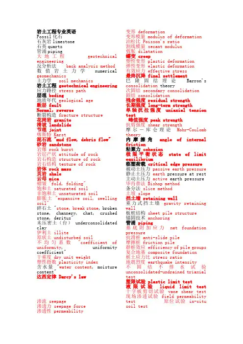
岩土工程专业英语Fossil化石石灰岩limestone石英quartz管涌piping大地工程geotechnical engineering反分析法back analysis method 数值岩土力学numerical geomechanics土力学soil mechanics岩土工程 geotechnical engineering 应力路径stress path层理beding地质年代geological age断层 faultNormal,reverse断裂构造fracture structure花岗岩 granite滑坡 landslide节理 joint喀斯特 Karst泥石流 "mud flow, debris flow" 砂岩 sandstone岩爆 rock burst岩层产状 attitude of rock岩石构造 structure of rock岩石结构 texture of rock岩体 rock mass页岩 shale云母 mica褶皱 "fold, folding"饱和土 saturated soil非饱和土 unsaturated soil膨胀土 "expansive soil, swelling soil"碎石土 "stone, break stone, broken stone, channery, chat, crushed stone, deritus"未压密土(台) underconsolidated clay伊利土 illite原状土 undisturbed soil不均匀系数"coefficient of uniformity, uniformity coefficient"干重度 dry unit weight塑性指数 plasticity index含水量"water content, moisture content"达西定律 Darcy's law渗流 seepage渗透力 seepage force渗透性 permeability 变形 deformation变形模量 modulus of deformation泊松比 Poisson's ratio割线模量 secant modulus剪胀 dilatation蠕变 creep塑性变形 plastic deformation弹性变形 elastic deformation有效应力 effective stress最终沉降 final settlement巴隆固结理论Barron'sconsolidation theory次固结 secondary consolidation固结 consolidation残余强度 residual strength长期强度 long-term strength单轴抗拉强度uniaxial tensiontest峰值强度 peak strength抗剪强度 shear strength摩尔-库仑理论Mohr-Coulombtheory内摩擦角angle of internalfriction粘聚力cohesion极限平衡状态state of limitequilibrium临塑荷载critical edge pressure被动土压力passive earth pressure静止土压力earth pressure at rest主动土压力active earth pressure毕肖普法 Bishop method条分法slice method土坡 slope挡土墙 retaining wall重力式挡土墙gravity retainingwall板桩结构sheet pile structure锚固技术anchoring管涌piping基底附加应力net foundationpressure抗滑桩 anti-slide pile摩擦桩 friction pile群桩效应 efficiency of pile groups复合地基 composite foundation桩土应力比 stress ratio地震烈度 earthquake intensity不固结不排水试验unconsolidated-undrained triaxialtest塑限试验 plastic limit test液限试验liquid limit test十字板剪切试验vane shear test 现场渗透试验 field permeabilitytest 原位试验in-situsoil test岩石力学英语专业词汇 anchored cables 锚索 forces in cables 锚索中的力 An-isotropy 各向异性,有向性,非均质性 Anticline 背斜 向斜(syncline ) arch dams 拱坝 arch gravity dams 重力拱坝,拱形重力坝 Austrian method 奥地利施工法 NATM (New Austrian Tunnelling Method ) 新奥法 ~ for tunnel lining 奥地利隧道支护法 Basalt 玄武岩 Bedding joints 层理 Biotite 黑云母 Bolts (同rock bolts) 锚杆 bore holes 钻孔 brittle fracture of rock 岩石脆性破坏,岩石脆性断裂 Calcite 方解石 classification of rocks 岩石分类 rock slides 岩石滑动,岩石滑移 Sandstones 砂岩 Strain-stress curves 应力-应变曲线 Cobble 大卵石 collapse of tunnel roof or wall 隧道冒顶或片帮 Concrete 混凝土 contour diagrams 等高线图,轮廓线图 convergence in tunnels 隧道中的收敛 Coulomb (Coulomb-Mohr )law of shear 库仑(库仑-莫尔)剪应力定律或准则 crushing of rock masses 岩石破碎 ~ round tunnels 隧道周围的岩体破碎 dam foundations 坝基础 density of rock 岩石密度 Displacements 位移 dynamic tests 动态试验 effective stress 有效应力 failure of rock 岩石破坏,岩石断裂 brittle failure, shear failure, tensile failure, visco-plastic failure 脆性破坏,剪切破坏,拉伸破坏,粘-塑形破坏 progressive failure of rock mass 岩体的渐进破坏 finite element method (f. e. m.)of numerical stress analysis 岩石应力分析的有限元方法 fissure in rock 岩石中的裂纹,岩石中的裂缝 fractures of rock 岩石断裂,岩石裂缝 Friction 摩擦 angle of Friction 摩擦角 hardness of rocks 岩石的硬度 horizontal stress 水平应力 hydrostatic pressure 静水压力 in situ tests and measurements 现场试验与测量 International Society of rock mechanics 国际岩石力学协会,国际岩石力学学会 jack 千斤顶 ~ in toe of dam 位于坝趾的千斤顶 joint 节理 strength of ~ 节理强度 Jurassic rock 侏罗纪岩石 Laplace equation 拉普拉斯方程 Macrofractures 宏观裂纹 Marble 大理石 Microfractures 微观破坏,、微观断裂 mining engineering 采矿工程 modulus of elasticity (Young modulus )弹性模量(杨氏模量) Mohr circle 莫尔圆 moment , 力矩 Mudstone 泥岩 Openings 峒室,巷道 circular ~ 圆形巷道,圆形峒室 Darcy ’s law for ~ 达西岩石渗水定律 permeability factor K 渗透性系数 Phyllite 千枚岩,硬绿泥岩 physical properties of rock 岩石的物理性质 plastic deformation of rock 岩石的塑性变形 Poisson ’s ratio 泊松比pore pressure 孔隙压力 power stations 地下电站pulvino (pressure distribution slab)压力分布板 rock quality designation 岩石质量指标 Quartz 石英rate of loading 加载率relaxation of rock masses 岩体的松弛 rock bolting 岩石锚杆,岩石锚杆支护 safety factor 安全系数 scale effect 尺寸效应 seismic wave tests on rock; on dam site 岩石的,坝址的地震波试验shear stress剪应力Shotcrete喷射混凝土Slope斜坡,边坡stability of ~边坡稳定性sonic waves声波Steel钢,钢材arches of ~钢拱形支架Survey测量geological ~地质测量geophysical ~地球物理测量tensile strength抗拉强度tension joint张节理,受拉接头triaxial compression test三轴压缩试验Tunnels隧道,巷道lining of ~隧道支护vertical stress垂直应力void ratio空隙比volumetric strain-stress curve体积应变-应力曲线water pressure水压water table水位,地下水位地震烈度 earthquake intensity 一:单词翻译①strain-stress activ应力-应变活动②seepage 渗透③cohesion内聚力④the texture and structure 结构和构造⑤consolidation 固结⑥angle of meternal friction内摩擦角⑦geotechnical engineering岩土工程⑧beding 层理⑨fault 断层⑩joint 节理11.fold褶皱 ndslide滑坡13.sandstone砂岩 14.illite 伊利土 15.Darcy’s law 达西定律 16.saturated soid 饱和土17.effective stress有效应力18.secondary consolidation次固结19. granite花岗岩 20.basalt玄武岩 21.marble大理岩22. passive earth pressure被动土压力23.earth pressure at rest静止土压力 24.active earth pressure主动土压力25.NATM新奥法26.RQD岩石质量系数 27.moment 力矩28.quaritz石英29.void vatio 空隙比30.couples力偶 31.failure破坏32.soil texture 土壤33.lining 支衬 34.bolts 锚钉35.cable 锚索 36.pile 桩37.IAEG(international association of engineering geology) 国际工程地质学会38.ISRM(International Societv of ReconstructiveMicrosurgery,Australia) 国际岩石力学学会39. ASCE(The American Society of Civil Engineers) 美国土木工程师学会40.anticlines 背斜41.synclines向斜42.normal 正断层43.reverse 逆断层44.left-lateral 平移断层环境与土木工程学院: College of Enviroment and Civil Engineering (Chengdu University of Technology )压缩法、混成法.符号法和宇母象形法.合成法由相互独立的两个或更多的词合成得到新词派生法通过对词根加上各种前缀或后缀来构成新词翻译过程一般经过三个阶段:理解、表达、校对a building project of high-rise apartment houses高层公寓大楼的建筑项目one of the common defects in tunnel maintenance隧道养护中普遍存在的问题之一二.简答或填空1.三大检索 SCI(科学引文索引) EI(工程索引) ISTP(科技会议录)2.岩石边坡破坏类型四大类①planar failure 极限平衡分析(平面型)②wedge failure 赤平投影法③rotational 条分法(圆弧型)④toppling 数值计算 3.岩土工程三门专业基础课 工程地质engineering geology 岩石力学rock mechanics 土力学oil mechanics 4.摘要四大部分 报道性摘要(informative abstract) (2)指示性摘要(indicative abstract) 报道-指示性摘要(informative- indicative abstract) ①背景信息,目的陈述what I want to do? ②方法论和语法how ido it ③研究结果/发现 what results did I get and conclusions can I draw? ④研究所带来的启示/结论what is and original this paper 5.岩土工程专业英语特点客观性(Objective )、准确性(accuracy )和精练性(conciseness) ①广泛使用被动语态①mathematics is used in many different fields, ②People use mathematics in many different fields, ②广泛使用非谓语形式The signal should be filtered before it is amplified. The signal should be filtered before being amplified ③省略句使用频繁If it is possible, the open-loop control approach should be used in this system. If possible, the open-loop control approach should be used in this system. ④It 句型和祈使句使用频繁 ⑤复杂长句使用频繁It has been mentioned above that the electrons in a metal are able to move freely through the metal, that their motion constitutes an electric current in the metal and that they play an important part ⑥后置形容词短语作定语多(of ) 省略句使用频繁 As already discussed 前已讨论If so 倘若如此 As previously mentioned 前已提到 When needed (necessary, feasible)必要时 Where feasible 在实际可行的场合 Where possible 在可能的情况下 As explained before 前已解释 As described above 如上所示 If possible (necessary)如果可能 (必要)6.地层产状要素 strike(走向) dip(倾角) dip direction(倾向)7.岩石圈的演化过程 igneous rock(岩浆岩) metamorphic(变质岩) sedimentary(沉积岩) 三,句子翻译 1.a building project of high-rise apartment house. 高层公寓大楼的建筑项目 2.one of the common defects in tunnel maintenance 隧道养护中的普遍存在的问题之一 3.the forces keeping the beam stranght must,by a fundamental law of statics, equal the load tending to fold it up. 根据静力学原理,使梁保持平直的力必定等于将其压弯的荷载 4.about one third of all accidents happen when it is dark ,although obriously there is more traffic during daytime 大约三分之一的事故发生在黑夜,尽管明显有更多的交通事故发生在白天 5.such construction procedure can increase producticity over 3 times 这种程序可以提高生产力的3倍以上 6.the production cost has reduced four times 生产成本降低了四倍四:英文摘要填空The results with high precision are hard to achieve rapidly by means of conventional method such as theoretical analysis and numerical calculation; slope engineering is a highly complicated nonlinear system. A new prediction method based on Gaussian process (GP), as a probabilistickernel leaning machine and a powerful tool for solving highly nonlinear problems,is proposed for slope stability evaluation. The GP model for slope stability evaluation is established and applied to the practical engineering. The results show that the method can find the nonlinear mapping relationship between classifications of slope stability and influencing factors easily. Furthermore, the reasonable, reliable and probabilistic results of slope stability evaluation can be obtained quickly by using the method. In conclusion, the method is feasible, effective and simple to implement slope stability evaluation and to provide a new way for fast design of slope engineering.针对边坡工程是复杂的非线性系统,采用常规的理论分析和数值计算方法难以满足对边坡稳定性评价的高精度与快速性的要求,为此,提出对处理非线性复杂问题具有很好的适应性一种有概率意义的核学习机—高斯过程机器学习方法来解决边坡稳定性的合理评价问题,建立了相应的边坡稳定性预测模型。
地质专业词汇英语翻译(A-D) 2006-4-15 12:48:50 来源:生命经纬a horizon a 层位a lineation a 线理a twin a 双晶aa lava 块熔岩aalenian stage 阿林阶abandon 废弃abandoned mine 废弃的矿山abandoned well 废孔abatis 通风隔墙abdomen 腹部abdominal appendage 腹肢abdominal cavity 腹腔abdominal fin 腹abductor 外展肌abductor muscle 外展肌abernathyite 水砷钾铀矿aberration 象差abichite 光线矿abiogenesis 自然发生abiogeny 自然发生abiotic factor 非生物因素ablation 剥蚀ablation breccia 剥蚀角砾岩ablation moraine 消融碛ablation skin 熔蚀皮ablation till 消融碛ablykite 阿布石abnormal 异常的abnormal interference color 异常干涉色abnormal metamorphism 异常变质酌abolition 废除abrade 剥蚀abrasion 海蚀abrasion platform 磨蚀台地abrasion surface 浪蚀面abrasion terrace 磨蚀阶地abrasionn test 磨耗试验abrasive 磨料;海蚀的abrazite 多水高岭土absarokite 正边玄武岩absite 钍钛铀矿absolute age 绝对年龄absolute black body 绝对黑体absolute chronology 绝对年代学absolute dating 绝对年代测定absolute geopotential 绝对重力势absolute porosity 绝对孔隙率absolute pressure 绝对压力absolute structure 绝对构造absorbed water 吸附水absorbent 吸收剂absorber 吸收器absorbing well 吸水井absorption 吸收absorption axis 吸收轴absorption border 融蚀缘absorption curve 吸收曲线absorption edge 吸收端absorption factor 吸收率absorption spectrum 吸收光谱absorptive capacity 吸收率absorptivity 吸收性abukumalite 铋磷灰石abundance 丰度abundance of elements 元素丰度abundance of isotopes 同位素丰度abundance ratio of isotopes 同位素相对丰度abysmal deposits 深海沉积物abyss 深海abyssal 深海的abyssal benthic zone 深渊底栖带abyssal deposits 深海沉积物abyssal facies 深海相abyssal hills province 深海丘陵区abyssal injection 深成贯入abyssal rock 深成岩abyssal sediments 深海沉积物acadialite 红菱沸石acadian stage 阿卡德阶acalycine 无花萼的acanthite 螺状硫银矿acanthoid 刺状的acaulescent 无茎的acaulous 无茎的acaustobiolite 非燃性生物岩accelerated development 上升发育acceleration 促进酌accelerometer 加速度计accessory 副的accessory ejecta 早成同源抛出物accessory minerals 副矿物accidental ejecta 异源抛出物accidental inclusion 外源包体accidental species 偶见种accidental xenolith 外源包体acclivity 上坡accompanying mineral 伴生矿物accordance of summit levels 山峰高度一致accordant junction 交合汇流accordion fold 棱角褶皱accretion 附加体accretion gley 结核潜育层accretion theory 吸积理论accretionary lapilli 团积火山砾accumulate 堆积accumulated temperature 积温accumulation 堆积accumulation horizon 聚积层accumulation moraine 堆积冰碛accumulation terrace 堆积阶地accumulation theory of volcano 火山堆积说accumulation till 堆积冰碛accumulative phase 堆积相accuracy 准确度acephalous 无头的acephalous larva 无头幼虫acerous 针状的acetate 醋酸盐acetic acid 醋酸acf diagram acf 图解achavalite 硒铁矿achiardite 坏晶石achirite 透视石achlusite 钠滑石achondrite 无球粒陨石achroite 无色电气石achromaite 浅闪石achromatic body 消色物体achromatic lens 消色差透镜achromatism 消色差achromatize 消色acicular 针状的aciculiform 针状的acid base equilibrium 酸碱平衡acid earth 酸性白土acid humus 酸性腐殖质acid mine drainage 酸性矿水排水acid plagioclase 酸性斜长石acid rock 酸性岩acid soil 酸性土acid solution 酸性溶液acid spring 酸性泉acid treatment of oil payzone 油层酸处理acid treatment of well 井的酸处理acidic lava 酸性熔岩acidification 酸化acidimetry 酸量滴定法acidite 酸性岩acidity 酸度acidizing of well 井的酸处理acidophilous plants 适酸植物acidotrophic lake 酸性营养湖acidulation 酸化acline twin 翻底双晶acmite 锥辉石acotyledon 无子叶植物acotyledonous 无子叶的acoustic basement 声波基底acoustic foundation 声波基底acoustic logging 声波测井acquired character 获得形质acre foot 英亩英尺acrobatholithic 露岩基的acrochordite 球砷锰矿acrospore 顶生孢子actinides 锕系元素actinium 锕actinolite 阳起石actinolite asbestos 阳起石石棉actinolite schist 阳起片岩actinolitic greenschist facies 阳起绿色片岩相actinometer 日射表actinometry 光化测定actinomorphic 辐射对称的actinomorphous 辐射对称的actinomyces 放线菌类actinostele 星状中柱actinouranium 锕铀actinula 辐射幼虫activated adsorption 活化吸附activated carbon 活性炭activated clay 活化粘土activated complex 活化络合物activated water 活化水activation 活化activation analysis 活化分析activation cross section 活化截面activation energy 活化能activation logging 活化测井activation method 活化法activation of platform 地台活化activator 活化剂active fault 活断层active folding 活褶曲酌active glacier 活动冰川active humus 活性腐殖质active hydrogen 活性氢active plate 移动板块active remote sensing 织式遥感active tectonic pattern 活动构造型式active volcano 活火山active water 侵蚀性水activity 活度activity coefficient 活度系数activization 活化酌activization platform block 活化台块actual reserves 实在储藏量actual volume 实际容积actualily 真实actualism 现实论actuopalaeontology 现实古生物学acute 急尖的acute bisectrix 锐角等分线acutifoliate 尖叶的adamant 硬石adamantine 坚硬的adamantine lustre 金刚光泽adamantine spar 刚玉adamellite 石英二长岩adamine 水砷锌矿adamite 水砷锌矿adamsite 暗绿云母adaptability 适应性adaptation 适应adaptive radiation 适应辐射adcumulate 累积岩addition 添加additional phase 加成相adductor 收肌adductor muscle scar 收肌筋痕adelite 砷钙镁石adelogenic 显衡隐晶质的adelpholite 铌铁锰矿adenoid 腺样的adergneiss 脉状片麻岩adhering 粘附性的;附着adhesion 粘附adhesive disk 吸盘adhesiveness 胶糟性adiabat 绝热线adiabatic cooling 绝热冷却adiabatic curve 绝热线adiabatic equilibrium 绝热平衡adiabatic heating 绝热增温adiabatic lapse rate 绝热温度梯度adiabatic process 绝热过程adiabatic state 绝热状态adiabatic temperature gradient 绝热温度梯度adiagnostic 隐微晶质的adigeite 镁蛇纹石adinole 钠长英板岩adipocerite 伟晶腊石adipocire 伟晶腊石adipose cell 脂细胞adit 平峒adjacent rock 围岩adjacent sea 边缘海adjoining rock 围岩adjustment 蝶admimistration 管理admission 收气adobe 灰质粘土adoral 口侧的adsorbent 吸附剂adsorbing material 吸附剂adsorption 吸附adsorption indicator 吸附指示剂adsorptive capacity 吸附能力adular 冰长石adularia 冰长石adult 成体advance 前进adventitious plants 外来植物adventive crater 寄生火口adventive volcano 寄生火山aecidiospore 锈孢子aeciospore 锈孢子aegirine 霓石aegirine augite 霓辉石aegirite 霓石aenigmatite 三斜闪石aeolian clastics 风成碎屑岩aeolian deposit 风积aeolian landform 风成地形aeolian soil 风积土aeration 充气aeration tissue 通气组织aeration zone 饱气带aerenchyma 通气组织aerial method of geology 航空地质甸方法aerial photography 航空摄影学aerial ropeway 架空死aerial survey 航空测量aerial triangulation 航空三角测量aerify 使呈气态aerobe 需气生物aerocartograph 航空测图仪aerogenous rock 风成岩aerogeography 航空地理学aerogeology 航空地质学aerolite 石陨石aerolith 石陨石aeromagnetic survey 航空磁测aerophotogeological map 航空摄影地质图aerophotogrammetry 航空摄影测量学aerophotography 航空摄影学aerophotography of geology 地质专业航空摄影aeroplankton 大气浮游生物aeroradioactive survey 航空放射性测量aerosiderite 铁陨石aerosiderolite 铁石陨石aerosite 深红银矿aerugite 块砷镍矿aeschynite 易解石affiliation 亲缘关系affine deformation 均匀变形affinity 亲和力afflux 汇入after deep 后渊aftereffect 后效aftershock 余震afwillite 桂硅钙石agalite 纤滑石agalmatolite 寿山石agamogony 无配子生殖agate 玛瑙age 龄期age determination 时代鉴定age of cycads 苏铁植物时代age spectra 年龄谱ageing of colloids 胶体熟化agent of erosion 侵蚀力agents of metamorphism 变质营力ageostrophic wind 非地转风agglomerate 集块岩agglomerate lava 集块熔岩agglomeratic 集块岩状的agglomeration 烧结agglutinate 粘合集块岩agglutination 胶着agglutinin 凝集素aggradation 加积aggradation terrace 堆积阶地aggradational plain 堆积平原aggregate 集合体aggregation 聚集aggressive water 侵进水agitation 搅拌agmatite 角砾混合岩agnatha 无颌类agnolite 红硅钙锰矿agnotozoic era 元古代agpaite 钠质火成岩agreement 协议agricolite 闪铋矿agricultural geology 农业地质学agricultural geomorphology 农业地貌学agroforestrial geology 农林地质学agrogeology 农业地质学agrohydrologg 农业水文学aguilarite 辉硒银矿aidyrlite 杂硅铝镍矿aikinite 针硫铋铅矿air borne radioactivity 大气放射性air chamber 气室air compressor 空气压缩机air damping 空气制动air drilling 空气钻进air drying 风干air elutriation 空气淘析air flush drilling 空气冲洗钻井air gun 空气枪air hammer 气锤air lift 气动提升机air permeability 透气性air pressure 空气压力air release valve 放气阀air sac 气囊air separating tank 空气分离罐air separator 气力分离器air shrinkage 空气收缩air vent 排气孔air volcano 气火山airborne electromagnetic method 航空电磁法airborne electromagnetics 航空电磁法airborne magnetic prospecting 航空磁法勘探airborne magnetometer 航空地磁仪airborne remote sensing 航空遥感airborne survey 航空甸airial camera 航空摄影机airview 空瞰图airy phase 艾氏相airy's spiral 艾氏螺旋akaustobiolite 非燃性生物岩akaustobiolith 非燃性生物岩akerite 英辉正长岩akermanite 镁黄长石akf diagram akf图解akinete 厚壁孢子akrochordite 球砷锰矿aksaite 阿氏硼镁石ala twin 轴双晶alabandine 硫锰矿alabandite 硫锰矿alabaster 雪花石膏alabastrite 雪花石膏alamosite 铅灰石alar 翼状的alary 翼状的alaskaite 铅泡铋矿alaskite 白岗岩alate 有翼的albedo 反照率albers' equal area projection 亚尔勃斯等积投影albertite 黑沥青albian 阿尔布阶albian stage 阿尔布阶albite 钠长石albite twin 钠长石双晶albitite 钠长石玢岩albitization 钠长石化albitophyre 钠长斑岩alboranite 紫苏变玄岩aleurolite 粉砂岩aleuropelitic 粉砂泥的aleutite 易辉安山岩alexandrite 翠绿宝石algae 藻类algae control 藻类控制algal ball 海藻饼algal biscuit 海藻饼algal coal 藻煤algal fungi 藻菌类algal limestone 藻灰岩algal reef 藻礁algal structure 藻结构alginite 藻类体algodonite 微晶砷铜矿algology 藻类学algonkian 阿尔冈纪algonkian system 阿尔冈系algovite 辉斜岩aliphatic compound 脂族化合物alizarin 二羟蒽醌alkali 碱alkali alumina metasomatism 碱氧化铝交代alkali basaet 碱性玄武岩alkali earth metal 碱土金属alkali feldspar 碱性长石alkali flat 碱覆盖坪alkali gabbro 碱性辉长岩alkali granti 碱性花岗岩alkali lime index 碱灰质指数alkali metal 碱金属alkali olivine basalt 碱性橄榄玄武岩alkali pyroxene 碱性辉石alkali rock series 碱性岩系alkali salt 碱盐alkali soil 碱土alkali syenit 碱性正长岩alkalic rock 硷性岩alkalic ultrabasic rock 碱超基性岩alkalify 碱化alkalimetry 碱量滴定法alkaline amphibolization 碱性角闪石化alkaline earth 碱土族alkaline earth metal 碱土金属alkaline metasomatism 碱性交代酌alkaline pyroxenization 碱性辉石化alkaline rock 硷性岩alkaline rocks 碱性岩类alkaline soil 碱性土alkaline solution 碱性溶液alkaline spring 碱泉alkalinity 碱度alkalipicrite 碱性苦橄岩alkalitrophic lake 碱液营养湖alkalization 碱化酌alkalize 碱化alkaloid 生物碱alkanes 链烷烃allactite 砷水锰矿allagite 绿蔷薇辉石allalinite 浊变辉长岩allanite 褐帘石alleghanyite 粒硅锰矿allemontite 砷锑矿allite 铝铁土allivalite 橄榄钙长岩allobar 变压区allocation 分配allochemical metamorphism 异化变质allochetite 霞辉二长斑岩allochroite 粒榴石allochromatic colour 假色allochromatism 假色allochthone 移置岩体allochthonous 外来的allochthonous coal 异地生成煤allochthonous deposit 移积allochthonous fold 移置性褶曲allochthonous limestone 移置灰岩alloclastic breccia 火山碎屑角砾岩allogenic 他生的allogenic element 他生元素allogenic mineral 他生矿物allogenic succession 他生演替allomerism 异质同晶现象allometamorphism 他变酌allometry 异速生长allomigmatite 他混合岩allomorph 同质异形的allomorphism 同质异晶allomorphous 同质异形的allopalladium 硒钯矿allopatric polymorphism 同质多形allophane 水铝英石allophase metamorphism 他相变质alloskarn 外成夕卡岩allothigenic 他生的allothigenous 他生的allotriomorphic 他形的allotriomorphic granular texture 他形晶粒状结构allotriomorphic structure 他形构造allotriomorphic texture 他形结构allotrope 同素异形体allotropic modification 同素异形体allotropic transformation 同素异晶变化allotropism 同素异形allotropy 同素异形allotype 异模式标本alloy 合金alluvial 冲积的alluvial apron 山麓冲积扇alluvial channel 冲积河道alluvial cone 冲积锥alluvial deposit 冲积层alluvial fan 冲积扇alluvial fan deposit 冲积扇层alluvial ore deposit 冲积矿床alluvial placer 冲积砂矿床alluvial plain 冲积平原alluvial sand ripples 河成砂纹alluvial sand wave 河成沙波alluvial soil 冲积土alluvial terrace 冲积阶地alluvial veneer 冲积表层alluviation 冲积alluvion 冲积层alluvium 冲积层almandine 铁铝榴石almandite 铁铝榴石alnico 铝镍钴合金alnoite 黄长煌斑岩alp 高山alpha quartz 石英alpha ray spectrometer 能谱仪alphitite 岩粉土alpides 阿尔卑斯造山带alpine animals 高山动物alpine belt 高山带alpine orogeny 阿尔卑斯造山运动alpine type peridotite 阿尔卑斯式橄榄岩alpine type vein 阿尔卑斯型矿脉alpinotype orogeny 阿尔卑斯型造山酌alpinotype tectonics 阿尔卑斯型构造alsbachite 榴云细斑岩alstonite 碳碱钙钡矿altaite 碲铅矿altar 腋生的altazimuth 经纬仪alteration 蚀变alteration halo 蚀变晕alteration zone 蚀变晕altered aureole 蚀变晕altered mineral 蚀变矿物alternant 交替的alternate phyllotaxis 互生叶序alternately pinnate 互生羽状的alternating 交替alternating layers 互层alternation 互层alternation of beds 互层alternation of generations 世代交替alternative 可选择的altimeter 高度计altitude 高度altitudinal zonality 垂直分布带alum 茂alum shale 茂页岩alum slate 茂板岩alumian 无水矾石alumina 矾土aluminate 铝酸盐aluminite 矾石aluminum 铝alumochromite 铝铬铁矿alunite 茂石alunitization 茂石化alunogen 毛矾石alurgite 锰云母alveolar 蜂窝状alvite 铪锆石amagmatic 非岩浆活动的amalgam 汞齐amalgamation 混汞酌amarantite 红铁矾amazonite 天河石amazonitization 天河石化ambatoarinite 碳酸锶铈矿amber 钙铝榴石amberite 灰黄琥珀ambient 外界的ambiguity 多义性amblygonite 磷铝石ambrite 灰黄琥珀ambulacral foot 管足ambulacral system 步带系ambularcral zone 步带ameba 变形虫amendment 修正;校正americium 镅amesite 镁绿泥石ametaboly 无变态amethyst 紫水晶amherstite 反条正长闪长岩amianthus 石棉amino acid metabolism 氨基酸代谢aminobenzoic acid 氨基苯酸ammonioborite 水铵硼石ammonites 菊石类amorphous 非晶质的amorphous graphite 无定型石墨amorphous silica 无定形硅氧amosite 铁石棉amount 总计amount of evaporation 蒸发量amount of precipitation 降水量amount of throw 纵距ampangabeit 铌链铁铀矿ampelite 黄铁炭质页岩amphibia 两栖类amphibious plants 两栖植物amphibole 闪石amphibolite 闪岩amphibolite facies 角闪岩相amphibolization 闪石化酌amphigene 白榴石amphigenite 白榴熔岩amphiprotic 两性的ampholyte 两性电解质amphoteric 两性的amphoteric electrolyte 两性电解质amphoteric element 两性元素amphoteric ion 两性离子amphoteric oxide 两性氧化物amphoterite 无粒古橄陨石amplexicaul 抱茎的amplifier for photocurrents 光电僚大器amplitude 振幅amplitude correction 振幅校正amplitude spectrum 振幅谱amygdale 杏仁孔amygdaloid 杏仁岩amygdaloidal 杏仁状的amygdaloidal structure 杏仁状构造amygdule 杏仁孔anabatic wind 谷风anabolism 合成代谢anaboly 后加演化anaclinal 逆向的anadiagenesis 前进成岩酌anaerobe 厌气微生物anaerobic bacteria 嫌气细菌anaerobiosis 嫌气生活anagenesis 前进演化anal fin 臀anal gland 肛腺analbite 单斜钠长石analcime 方沸石analcimite 方沸岩analcimolith 方沸岩analcite 方沸石analog 相似体analogous organ 同功瀑analogue 相似体analogy 类似analysis by sedimentation 沉积分析analytic standard 分析标准analytical balance 分析天平anamesite 中粒玄武岩anamigmatism 深溶混合岩化anamorphic zone 合成变质带anamorphism 合成变质anaseism 背震中anastomose 网结anastrophen 倒装法anatase 锐钛矿anatectic magma 深熔岩浆anatectite 深熔混合岩anatexis 深熔酌anauxite 富硅高岭石anchieutectic 近底共融的anchimetamorphism 近变质酌anchimonomineralic 近单矿物的anchor ice 底冰ancient channel 古河道ancient elephant 古大象ancient landform 古地形ancylite 菱锶铬矿andalusite 红柱石andersonite 水碳钠钙铀矿andesine 中长石andesite 安山岩andesite line 安山岩线andorite 锑铅银矿andradite 钙铁榴石anemoclastics 风成碎屑岩anemophilous plant 风媒植物anemophily 风媒anemousite 三斜霞石angara flora 安加拉植物群angara shield 安加拉古陆angaraland 安加拉古陆angarides 安加拉古陆angiospermous 被子的angiosperms 被子植物angle of contact 接触角angle of draw 陷落角angle of incidence 入射角angle of inclination 倾斜角angle of internal friction 内摩擦角angle of reflection 反射角angle of refraction 折射角angle of repose 休止角angle of strike 走向角度angle of subsidence 陷落角angrite 钛辉无球粒陨石angular 有角的angular discordance 斜交不整合angular unconformity 钭文不整合angularity 有角angustifoliate 狭叶的anhedral 他形的anhydration 脱水anhydride 无水物anhydrite 硬石膏anhydrite formation 硬石膏层anhysteretic remanent magnetiazation 非滞后剩余磁化animal charcoal 动物煤animal debris 动物残余animal theory 动物成因论animikie system 安尼迷基系animikite 铅银砷镍矿anisian 安尼巫anisodesmic structure 蛤稳变异构造anisometric 非等轴的anisophyllous 不等叶的anisotrophism 蛤异性anisotropic 非均质的anisotropic fabric 蛤异性组构anisotropy 蛤异性anisotropy of crystals 晶体蛤异性ankaramite 钭长辉石岩ankaratrite 橄霞玄武岩ankerite 铁白云石anna aannabergite 镍华annealing recrystallization 退火重结晶酌annelids 环节动物annerodite 铌钇铀矿annite 羟铁云母annivite 铋铜矿annual 年刊annual amount of precipitation 年降水量annual plant 一年生植物annual ring 年轮annular 环状的annulation 环annulus 体环anomalous electric field 异常电场anomalous extinction 异常消光anomalous interference color 异常干涉色anomalous lead 异常铅anomalous upheaval 异常隆起anomaly 异常anomite 褐云母anonymous 不具名的anorogenic period 非造山期anorogenic time 非造山期anorthite 钙长石anorthitite 钙长岩anorthoclase 歪长石anorthosite 斜长岩antagonism 对抗酌antarctic 南极antarctica 南极大陆antecedent 先行的antecedent precipitation index 前期降雨指标antecedent river 先成河antecedent valley 先成谷anteclise 台背斜antegenetic river 原生河antenna 触角antennule 第一触角anther 药antheridium 精子囊antholite 直闪石anthophyllite 直闪石anthozoa 珊烘类anthracite 无烟煤anthracite coal 无烟煤anthraconite 沥青灰岩anthraxolite 碳沥青anthraxylon 纯木煤anthropogenic factor 人为因素anthropogeography 人类地理学anthropoid 类人猿anthropoid apes ape 类人猿anthropology 人类学anthropophyte 人为植物anthropostratigraphy 人类地层学antibonding electron 反键电子anticathode 对阴极anticlinal 背钭的anticlinal axis 背斜轴anticlinal bend 背斜弯曲anticlinal dome 背斜隆起anticlinal fault 背斜断层anticlinal fold 背斜anticlinal limb 背斜翼anticlinal mountain 背斜脊anticlinal ridge 背斜脊anticlinal theory 背斜理论anticlinal trap 背斜圈闭anticlinal valley 背斜谷anticlinal zone 背斜带anticline 背斜anticlinorium 复背斜anticlise 台背斜anticlockwise 反时针方向的anticoincidence 反符合antidune 反沙丘antiferromagnetism 反铁磁性antifluorite structure 反萤石结构antiform 背斜型构造antiformal syncline 背斜型向斜antigorite 叶蛇纹石antimonite 辉锑矿antimony 锑antimony bloom 锑华antipathy 不相容antipertite 反纹长石antiseismic 抗震的antiseptic 防腐剂antistress mineral 反应力矿物antisymmetrization 反对称化antithetic fault 反向断层antlerite 块铜矾antofagastite 水氯铜矿anulus 体环apachite 闪辉响岩apatite 磷灰石aperiodicity 非周期性aperture 孔apex 背斜顶apex of shell 壳顶aphanic 显衡隐晶质的aphaniphyric 隐晶斑状aphanite 隐晶岩aphanitic texture 隐晶结构aphanitic variolitic texture 隐晶球颗结构aphotic zone 无光带aphrosiderite 铁华绿泥石aphthalose 钾芒硝aphthitalite 钾芒硝aphthonite 银铜矿aphyric 无斑隐晶质的apical disk 顶系apical system 顶系apjohnite 锰茂aplite 细晶岩aplitic 细晶状的aplitic facies 细晶岩相aplitic texture 细晶岩构造aplogranite 淡色花岗岩apoandesite 脱玻安山岩apobasalt 脱玻玄武岩apogee 远地点apogranite 变花岗岩apolar adsorption 非极性吸附apomagmatic 外岩浆的apomagmatic deposit 外岩浆矿床apophyllite 鱼眼石apophyse 岩枝apophysis 岩枝apospory 无孢生殖apparent 外观上的apparent density 视密度apparent dip 视倾斜apparent heave 视横断距apparent resistivity 视电阻率apparent resistivity curve 视电阻率曲线apparent resistivity map 视电阻率图apparent specific gravity 表观比重apparent velocity 视速度apperance of crystal 结晶外貌apple coal 软煤applied geochemistry 应用地球化学applied geology 应用地质学applied geomorphology 应用地形学applied geothermics 应用地热学applied geothermy 应用地热学applied palaeontology 应用古生物学applied seismology 应用地震学appraisement 评价apron reef 石中住裙礁aptian 阿普第阶aptian stage 阿普第阶aqua regia 王水aquamarine 海蓝宝石aquatic 水生的aquatic animals 水栖动物aqueduct 沟渠aqueous deposit 水成沉积aqueous rock 水成岩aqueous soil 水成土aqueous solution 水溶液aquiclude 隔水层aquifer 含水层aquifer loss 含水层损失aquifer storage 合水层储水aquifer test 含水层试验aquiferous 含水的aquifuge 不透水层aquitanian stage 阿启坦阶aquitard 弱含水层arachnidea 蛛形类araeoxene 钒铅锌矿aragonite 文石arakawaite 磷锌铜矿aramayoite 硫铋锑银矿arandisite 硅锡矿arborescent 被状arc of compression 褶皱弧arc of folding 压缩弧arch 背斜archaean era 太古代archaeocyte 原始细胞archaeogeology 考古地质学archaeopteris flora 古蔽属植物群archaeopteryx 始祖鸟属archaeozoic 太古代的archaian 太古代的archbend 褶皱头部archean 太古代archean greenstone belt 太古代绿岩带arched structure 隆起构造archegone 颈卵器archegonium 颈卵器archeomagnetism 太古磁性archeophytic era 太古植物代archeozoic era 太古代archetype 原始型archipelagic apron 群岛沿边漫坡海底archipelago 群岛arcogenesis 地穹运动arcogeny 地穹运动arctic 北极圈arctic air mass 北极气团arctic front 北极锋arctic plants 北极植物arctic subregion 北极亚区arctoalpine 北极高山的arcuate 弓形的arcuate delta 弓形三角洲ardealite 磷石膏ardennite 锰硅铝矿area 分布区area of artesian flow 自廉区area of influence 影响区域areal eruption 区域喷溢arenaceous 砂屑的arenaceous rock 砂质岩arenaceous texture 砂质结构arenes 粗砂arenopelitic 砂泥质的arenose 粗砂质的arfvedsonite 钠钙闪石argentiferous 含银的argentite 辉银矿argentobismutite 硫银铋矿argentojarosite 辉银黄钾铁矾argentopyrite 含银黄铁矿argil 白粘土argillaceous 泥质的argillaceous limestone 泥质灰岩argillite 泥岩argillization 泥化argon 氩argyrodite 硫银锗矿arid basin 干燥盆地arid landform 干旱地形arid peneplain 干旱准平原arid zone 干旱带aridity coefficient 干燥系数aridity index 干燥指数ariegite 尖榴辉岩arithmetical averaging grade 算术平均品位arithmetical averaging thickness 算术平均厚度arizonite 红钛铁矿arkite 白榴霞斑岩arkose 长石石英岩arkosic sandstone 长石石英岩armangite 砷锰矿armored cone 熔壳火山锥armored fishes 甲胄鱼纲aromatic base crude oil 芳香基原油arrangement 配置arroyo 干谷arsenate 砷酸盐arsenic 砷arseniopleite 红砷铁矿arseniosiderite 钙砷铁矿arsenite 砷华arsenoclasite 水砷锰石arsenolite 砷华arsenomiargyrite 砷辉锑银矿arsenopyrite 毒砂arterite 层混合岩artesian aquifer 自廉层artesian basin 自廉盆地artesian ground water 自霖下水artesian pressure head 承压水位artesian spring 自联artesian water 自廉artesian well 自廉arthropoda 节肢动物artic front 北极峰articulation 关节artificial 人为的artificial classification 人为分类artificial crystal 人造晶体artificial diamond 人造金刚石artificial discharge 人工排泄artificial earth's satellite 人造地球卫星artificial earthquake 人为地震artificial ground water 人工地下水artificial hypocenter 人工震源artificial mineral 人造矿物artificial radio element 人工放射元素artificial radioactivity 人工放射性artificial recharge 人工补给artificial satellite 人造卫星artificial seismic source 人工震源artificial selection 人工淘汰artinite 纡维菱镁矿artinsk stage 阿丁斯克阶artinskian 阿丁斯克阶asbestos 石棉asbestus 石棉asbolane 钴土矿asbolite 钴土矿ascending development 上升发育ascension theory 上升说ascent curve 上升曲线aschaffite 云英钭煌岩ascharite 硼镁石aschistic 岩浆同质的aschistic dike 未分异岩脉aschistic dyke 未分异岩脉aschistite 未分异岩ascon type 单沟型ascospore 子囊孢子ascus 子囊aseismic 无震的asexual generation 无性世代asexual reproduction 无性生殖ash bed 火山灰层ash cloud 灰云ash cone 火山灰丘ash content of coal 煤灰分ash fall 降落灰ash flow 火山灰流ash free 无灰分的ash shower 降落灰ash structure 火山灰构造ashgillian stage 阿石极阶ashing 灰化asmanite 陨鳞石英asparagolite 黄绿磷灰石asparagus stone 黄绿磷灰石asperite 玻质英安岩asphalt 地沥青asphalt sealing trap 沥青塞圈闭asphaltenes 沥青质asphaltic base crude oil 沥青基原油asphaltic pyrobitumen 焦性沥青asphaltite 沥青岩asphaltum 地沥青aspite 盾状火山asporous 无孢子的assay 试金assay balance 试金天平assay map 采样平面图assaying 试料分析assessment well 估价井assimilate 同化assimilation 岩浆的同化酌associate 使联合associate species 伴生种associate structure 伴生构造associated mineral 伴生矿物associated ore 伴生矿association 联合association of elements 元素的共生组合assyntite 钛辉方钠正长岩assypite 钠橄辉长岩astable 不稳定的astatic 无定向的astatic magnetometer 无定向磁力仪astaticism 无定向性astatine 砹astatisation 无定向化asteroid 小行星asthenosphere 软力astian stage 阿斯蒂阶astite 红柱角页岩astrakhanite 白钠镁矾astroblem 古陨挥astrogeology 天体地质学astrophyllite 星叶石asymmetric 不对称的asymmetric carbon atom 不对称碳原子asymmetric dispersion 不对称色散asymmetric fold 不对称褶皱asymmetrical 不对称的asymmetrical anticline 不对称背斜asymmetrical crystal monochromator 不对称结晶单色仪asymmetrical ridge 不对称山脊asymmetry 非对称asynchronous 异步的atacamite 氯铜矿atatschite 线玻正斑岩atavism 返祖ataxic mineral deposit 不成层矿床ataxite 角砾斑杂岩ataxitic 角砾斑杂状的atectonic 非构造的atelestite 砷酸铋矿atlantic ocean 大误atlantic suite 大误岩套atlasspat 纤维石atmoclast 气碎岩atmoclastic rock 气碎岩atmoclastics 气碎岩atmogenic metamorphism 气生变质atmometer 蒸发表atmophile element 亲气元素atmosphere 大气圈atmospheric pressure 气压atmospheric rock 气成岩atmospheric weathering 大气风化atmospheric window 大气窗口atmospheric windows 大气窗口atoll 环礁atoll lake 环礁湖atoll texture 环礁结构atomic binding 原子键atomic bond 原子键atomic disintegration 原子衰变atomic energy level 原子能级atomic mass unit 原子质量单位atomic ratio 原子比atomic size 原子大小atomic spectrum 原子光谱atomic unit 原子单位atomic volume 原子体积atomistics 原子论atrio 火口原atrio lake 火口原湖atriopore 围鳃腔atrium 围鳃腔attenuation 衰减attenuation constant 衰减常数attenuation factor 衰减常数attraction 引力attribute 属性attrition 磨损attritus 碎集煤atypical 非典型的aubrite 顽火辉石无球粒陨石auerlite 磷钍矿augelite 光彩石augen structure 眼状构造augengneiss 眼环片麻岩auger 螺旋钻auger drill 螺旋钻augite 辉石augitite 辉石岩aulacogene 古断槽aureole 接触圈aurichalcite 绿铜锌矿auriferous 含金的auriferous conglomerate 含金砾岩auripigment 雌黄aurora 极光auroral zone 极光地带australite 澳洲似黑曜岩authigene 自生的authigenesis 自生酌authigenic 自生的authigenic element 自生元素authigenic mineral 自生矿物authigenous 自生的auto injection 自注入autobreccia 同生角砾岩autobreccited lava 同生角砾岩熔岩autocatalysis 自动催化autochthone 原地岩体autochthonous 原地的autochthonous coal 原地生成煤autochthonous deposit 原地沉积autochthonous fold 原地褶皱autochthonous granite 原地花岗岩autochthonous limestone 原地灰岩autoclases 自碎autoclast 自碎岩autoclastic 自碎的autoclastic rock 自碎岩autoclave 压热器高压锅autocorrelation function 自相关函数autogenic succession 自发演替autogeny 自生autogeosyncline 自地槽autointrusion 自侵入autolith 同源包体autometamorphism 自变质酌autometasomatism 自交代酌automolite 铁锌晶石automorphic 自形的autopneumatolysis 自气化酌autoradiography 自动射线照相术autotrophism 自养autotrophy 自养autotype 自型autunite 钙铀云母auversian stage 奥伯斯阶auxiliary curve 辅助曲线auxiliary fault 副断层auxiliary joint 副节理auxiliary mineral 副矿物available relief 有效起伏available water 可利用的水avalanche 雪崩avalanche breccia 岩崩角砾岩aven 落水洞aventurine 砂金石average life 平均寿命avezacite 钛铁辉闪脉岩avicennite 褐铊矿aviolite 堇云角页岩avogadrite 氟硼钾石awaruite 铁镍矿axe stone 软玉axial 轴的axial angle 光轴角axial colour 轴色axial distribution analysis 轴向分布分析axial plane 轴面axial plane cleavage 轴面劈理axial plane folding 轴面褶皱axial plane foliation 轴面叶理构造axial plane schistosity 轴面片理axial ratio 轴率axial section 轴向剖面axial skeleton 轴骨axial trace 轴迹axillary 腋生的axillary bud 腋芽axinite 斧石axinitization 斧石化axiolite 椭球粒axiolith 椭球粒axiolitic 椭球粒状的axis ?BR>axis of rotation 旋转轴axis of rotatory reflection 回转反射轴axis of symmetry 对称轴axis plane 轴面azeotrope 共沸混合物azeotropy 共沸性azilian age 阿齐尔时代azimuth 方位角azimuthal equal area projection 等积方位投影azimuthal equidistant projection 等距方位投影azimuthal orthomorphic 正形方位投影azimuthal projection 方位投影azimuthal quantum number 方位角量子数azoic era 无生代azurite 蓝铜矿babel quartz 塔状石英babingtonite 铁灰石bacillite 杆雏晶束back 背back deep 次生优地槽back flow 逆流back radiation 逆辐射back reflection camera 逆反射照相机back swamp 河漫滩沼泽backfill 充填background value 背景值backland 腹地backpressure 回压backshore 后滨backwash 回流backwashing method 回哩backwater 回水bacteria 细菌bacterial analysis 细菌分析bacterielles fossil 细菌化石baculite 杆菊石bad land 恶劣地baddeleyite 斜锆石badenite 镍铋砷钴矿baectuite 白头岩bag of ore 矿袋bagrationite 铈黑帘石bahiaite 橄闪紫苏岩baikalite 易裂钙铁辉石bailer 簧头;捞砂筒bajocian 巴柔阶bakerite 纤硼钙石baking coal 粘结煤balance 平衡balance resources 表内储量balanced filter 衡均滤波器balas 玫红尖晶石ball clay 球土ball diorite 球状闪长岩ball granite 球状花岗岩ball ironstone 球状铁矿石ball mill 球磨机ball porphyry 球状斑岩ball structure 球状构造ball texture 球状结构ballas 工业用球面金刚石balling 球团balsam 香胶baltic shield 波罗的地盾banakite 粗绿岩banatite 正辉英闪长岩band 带;夹层。
土木工程专业外语词汇大全中英翻译1. 综合类大地工程geotechnical engineering反分析法back analysis method基础工程foundation engineering临界状态土力学critical state soil mechanics数值岩土力学numerical geomechanics土soil, earth土动力学soil dynamics土力学soil mechanics岩土工程geotechnical engineering应力路径stress path应力路径法stress path method2. 工程地质及勘察变质岩metamorphic rock标准冻深standard frost penetration冰川沉积glacial deposit冰积层(台)glacial deposit残积土eluvial soil, residual soil层理beding长石feldspar沉积岩sedimentary rock承压水confined water次生矿物secondary mineral地质年代geological age地质图geological map地下水groundwater断层fault断裂构造fracture structure工程地质勘察engineering geological exploration海积层(台)marine deposit海相沉积marine deposit花岗岩granite滑坡landslide化石fossil化学沉积岩chemical sedimentary rock阶地terrace节理joint解理cleavage喀斯特karst矿物硬度hardness of minerals砾岩conglomerate流滑flow slide陆相沉积continental sedimentation泥石流mud flow, debris flow年粘土矿物clay minerals凝灰岩tuff牛轭湖ox-bow lake浅成岩hypabyssal rock潜水ground water侵入岩intrusive rock取土器geotome砂岩sandstone砂嘴spit, sand spit山岩压力rock pressure深成岩plutionic rock石灰岩limestone石英quartz松散堆积物rickle围限地下水(台)confined ground water 泻湖lagoon岩爆rock burst岩层产状attitude of rock岩浆岩magmatic rock, igneous rock岩脉dike, dgke岩石风化程度degree of rock weathering 岩石构造structure of rock岩石结构texture of rock岩体rock mass页岩shale原生矿物primary mineral云母mica造岩矿物rock-forming mineral褶皱fold, folding钻孔柱状图bore hole columnar section3. 土的分类饱和土saturated soil超固结土overconsolidated soil冲填土dredger fill充重塑土冻土frozen soil, tjaele非饱和土unsaturated soil分散性土dispersive soil粉土silt, mo粉质粘土silty clay高岭石kaolinite过压密土(台)overconsolidated soil红粘土red clay, adamic earth黄土loess, huangtu(China)蒙脱石montmorillonite泥炭peat, bog muck年粘土clay年粘性土cohesive soil, clayey soil膨胀土expansive soil, swelling soil欠固结粘土underconsolidated soil区域性土zonal soil人工填土fill, artificial soil软粘土soft clay, mildclay, mickle砂土sand湿陷性黄土collapsible loess, slumping loess素填土plain fill塑性图plasticity chart碎石土stone, break stone, broken stone, channery, chat, crushed sto ne, deritus未压密土(台)underconsolidated clay无粘性土cohesionless soil, frictional soil, non-cohesive soil岩石rock伊利土illite有机质土organic soil淤泥muck, gyttja, mire, slush淤泥质土mucky soil原状土undisturbed soil杂填土miscellaneous fill正常固结土normally consolidated soil正常压密土(台)normally consolidated soil自重湿陷性黄土self weight collapse loess4. 土的物理性质阿太堡界限Atterberg limits饱和度degree of saturation饱和密度saturated density饱和重度saturated unit weight比重specific gravity稠度consistency不均匀系数coefficient of uniformity, uniformity coefficient触变thixotropy单粒结构single-grained structure蜂窝结构honeycomb structure干重度dry unit weight干密度dry density塑性指数plasticity index含水量water content, moisture content活性指数级配gradation, grading结合水bound water, combined water, held water界限含水量Atterberg limits颗粒级配particle size distribution of soils, mechanical composi tion of soil可塑性plasticity孔隙比void ratio孔隙率porosity粒度granularity, grainness, grainage粒组fraction, size fraction毛细管水capillary water密度density密实度compactionness年粘性土的灵敏度sensitivity of cohesive soil平均粒径mean diameter, average grain diameter曲率系数coefficient of curvature三相图block diagram, skeletal diagram, three phase diagram三相土tri-phase soil湿陷起始应力initial collapse pressure湿陷系数coefficient of collapsibility缩限shrinkage limit土的构造soil texture土的结构soil structure土粒相对密度specific density of solid particles土中气air in soil土中水water in soil团粒aggregate, cumularpharolith限定粒径constrained diameter相对密度relative density, density index相对压密度relative compaction, compacting factor, percent compa ction, coefficient of compaction絮状结构flocculent structure压密系数coefficient of consolidation压缩性compressibility液限liquid limit液性指数liquidity index游离水(台)free water有效粒径effective diameter, effective grain size, effective size有效密度effective density有效重度effective unit weight重力密度unit weight自由水free water, gravitational water, groundwater, phreatic water 组构fabric最大干密度maximum dry density最优含水量optimum water content5. 渗透性和渗流达西定律Darcy s law管涌piping浸润线phreatic line临界水力梯度critical hydraulic gradient流函数flow function流土flowing soil流网flow net砂沸sand boiling渗流seepage渗流量seepage discharge渗流速度seepage velocity渗透力seepage force渗透破坏seepage failure渗透系数coefficient of permeability渗透性permeability势函数potential function水力梯度hydraulic gradient6. 地基应力和变形变形deformation变形模量modulus of deformation泊松比Poisson s ratio布西涅斯克解Boussinnesq s solution残余变形residual deformation残余孔隙水压力residual pore water pressure超静孔隙水压力excess pore water pressure沉降settlement沉降比settlement ratio次固结沉降secondary consolidation settlement次固结系数coefficient of secondary consolidation地基沉降的弹性力学公式elastic formula for settlement calculation 分层总和法layerwise summation method负孔隙水压力negative pore water pressure附加应力superimposed stress割线模量secant modulus固结沉降consolidation settlement规范沉降计算法settlement calculation by specification回弹变形rebound deformation回弹模量modulus of resilience回弹系数coefficient of resilience回弹指数swelling index建筑物的地基变形允许值allowable settlement of building剪胀dilatation角点法corner-points method孔隙气压力pore air pressure孔隙水压力pore water pressure孔隙压力系数Apore pressure parameter A孔隙压力系数Bpore pressure parameter B明德林解Mindlin s solution纽马克感应图Newmark chart切线模量tangent modulus蠕变creep三向变形条件下的固结沉降three-dimensional consolidation settl ement瞬时沉降immediate settlement塑性变形plastic deformation谈弹性变形elastic deformation谈弹性模量elastic modulus谈弹性平衡状态state of elastic equilibrium体积变形模量volumetric deformation modulus先期固结压力preconsolidation pressure压缩层压缩模量modulus of compressibility压缩系数coefficient of compressibility压缩性compressibility压缩指数compression index有效应力effective stress自重应力self-weight stress总应力total stress approach of shear strength最终沉降final settlement7. 固结巴隆固结理论Barron s consolidation theory比奥固结理论Biot s consolidation theory超固结比over-consolidation ratio超静孔隙水压力excess pore water pressure次固结secondary consolidation次压缩(台)secondary consolidatin单向度压密(台)one-dimensional consolidation多维固结multi-dimensional consolidation固结consolidation固结度degree of consolidation固结理论theory of consolidation固结曲线consolidation curve固结速率rate of consolidation固结系数coefficient of consolidation固结压力consolidation pressure回弹曲线rebound curve井径比drain spacing ratio井阻well resistance曼代尔-克雷尔效应Mandel-Cryer effect潜变(台)creep砂井sand drain砂井地基平均固结度average degree of consolidation of sand-drained ground 时间对数拟合法logrithm of time fitting method时间因子time factor太沙基固结理论Terzaghi s consolidation theory太沙基-伦杜列克扩散方程Terzaghi-Rendulic diffusion equation先期固结压力preconsolidation pressure压密(台)consolidation压密度(台)degree of consolidation压缩曲线cpmpression curve一维固结one dimensional consolidation有效应力原理principle of effective stress预压密压力(台)preconsolidation pressure原始压缩曲线virgin compression curve再压缩曲线recompression curve主固结primary consolidation主压密(台)primary consolidation准固结压力pseudo-consolidation pressureK0固结consolidation under K0 condition8. 抗剪强度安息角(台)angle of repose不排水抗剪强度undrained shear strength残余内摩擦角residual angle of internal friction残余强度residual strength长期强度long-term strength单轴抗拉强度uniaxial tension test动强度dynamic strength of soils峰值强度peak strength伏斯列夫参数Hvorslev parameter剪切应变速率shear strain rate抗剪强度shear strength抗剪强度参数shear strength parameter抗剪强度有效应力法effective stress approach of shear strength 抗剪强度总应力法total stress approach of shear strength库仑方程Coulomb s equation摩尔包线Mohr s envelope摩尔-库仑理论Mohr-Coulomb theory内摩擦角angle of internal friction年粘聚力cohesion破裂角angle of rupture破坏准则failure criterion十字板抗剪强度vane strength无侧限抗压强度unconfined compression strength有效内摩擦角effective angle of internal friction有效粘聚力effective cohesion intercept有效应力破坏包线effective stress failure envelope有效应力强度参数effective stress strength parameter有效应力原理principle of effective stress真内摩擦角true angle internal friction真粘聚力true cohesion总应力破坏包线total stress failure envelope总应力强度参数total stress strength parameter9. 本构模型本构模型constitutive model边界面模型boundary surface model层向各向同性体模型cross anisotropic model超弹性模型hyperelastic model德鲁克-普拉格准则Drucker-Prager criterion邓肯-张模型Duncan-Chang model动剪切强度非线性弹性模量nonlinear elastic model盖帽模型cap model刚塑性模型rigid plastic model割线模量secant modulus广义冯·米赛斯屈服准则extended von Mises yield criterion广义特雷斯卡屈服准则extended tresca yield criterion加工软化work softening加工硬化work hardening加工硬化定律strain harding law剑桥模型Cambridge model柯西弹性模型Cauchy elastic model拉特-邓肯模型Lade-Duncan model拉特屈服准则Lade yield criterion理想弹塑性模型ideal elastoplastic model临界状态弹塑性模型critical state elastoplastic model流变学模型rheological model流动规则flow rule摩尔-库仑屈服准则Mohr-Coulomb yield criterion内蕴时间塑性模型endochronic plastic model内蕴时间塑性理论endochronic theory年粘弹性模型viscoelastic model切线模量tangent modulus清华弹塑性模型Tsinghua elastoplastic model屈服面yield surface沈珠江三重屈服面模型Shen Zhujiang three yield surface method双参数地基模型双剪应力屈服模型twin shear stress yield criterion双曲线模型hyperbolic model松岗元-中井屈服准则Matsuoka-Nakai yield criterion塑性形变理论谈弹塑性模量矩阵elastoplastic modulus matrix谈弹塑性模型elastoplastic modulus谈弹塑性增量理论incremental elastoplastic theory谈弹性半空间地基模型elastic half-space foundation model谈弹性变形elastic deformation谈弹性模量elastic modulus谈弹性模型elastic model魏汝龙-Khosla-Wu模型Wei Rulong-Khosla-Wu model文克尔地基模型Winkler foundation model修正剑桥模型modified cambridge model准弹性模型hypoelastic model10. 地基承载力冲剪破坏punching shear failure次层(台)substratum地基subgrade, ground, foundation soil地基承载力bearing capacity of foundation soil地基极限承载力ultimate bearing capacity of foundation soil地基允许承载力allowable bearing capacity of foundation soil地基稳定性stability of foundation soil汉森地基承载力公式Hansen s ultimate bearing capacity formula极限平衡状态state of limit equilibrium加州承载比(美国)California Bearing Ratio局部剪切破坏local shear failure临塑荷载critical edge pressure梅耶霍夫极限承载力公式Meyerhof s ultimate bearing capacity formula 普朗特承载力理论Prandel bearing capacity theory斯肯普顿极限承载力公式Skempton s ultimate bearing capacity formula太沙基承载力理论Terzaghi bearing capacity theory魏锡克极限承载力公式Vesic s ultimate bearing capacity formula 整体剪切破坏general shear failure11. 土压力被动土压力passive earth pressure被动土压力系数coefficient of passive earth pressure极限平衡状态state of limit equilibrium静止土压力earth pressue at rest静止土压力系数coefficient of earth pressur at rest库仑土压力理论Coulomb s earth pressure theory库尔曼图解法Culmannn construction朗肯土压力理论Rankine s earth pressure theory朗肯状态Rankine state谈弹性平衡状态state of elastic equilibrium土压力earth pressure主动土压力active earth pressure主动土压力系数coefficient of active earth pressure12. 土坡稳定分析安息角(台)angle of repose分析毕肖普法Bishop method分析边坡稳定安全系数safety factor of slope分析不平衡推理传递法unbalanced thrust transmission method分析费伦纽斯条分法Fellenius method of slices分析库尔曼法Culmann method分析摩擦圆法friction circle method分析摩根斯坦-普拉斯法Morgenstern-Price method分析铅直边坡的临界高度critical height of vertical slope分析瑞典圆弧滑动法Swedish circle method分析斯宾赛法Spencer method分析泰勒法Taylor method分析条分法slice method分析土坡slope分析土坡稳定分析slope stability analysis分析土坡稳定极限分析法limit analysis method of slope stability分析土坡稳定极限平衡法limit equilibrium method of slope stability 分析休止角angle of repose分析扬布普遍条分法Janbu general slice method分析圆弧分析法circular arc analysis13. 土的动力性质比阻尼容量specific gravity capacity波的弥散特性dispersion of waves波速法wave velocity method材料阻尼material damping初始液化initial liquefaction地基固有周期natural period of soil site动剪切模量dynamic shear modulus of soils动力布西涅斯克解dynamic solution of Boussinesq 动力放大因素dynamic magnification factor动力性质dynamic properties of soils动强度dynamic strength of soils骨架波akeleton waves in soils几何阻尼geometric damping抗液化强度liquefaction stress孔隙流体波fluid wave in soil损耗角loss angle往返活动性reciprocating activity无量纲频率dimensionless frequency液化liquefaction液化势评价evaluation of liquefaction potential液化应力比stress ratio of liquefaction应力波stress waves in soils振陷dynamic settlement阻尼damping of soil阻尼比damping ratio14. 挡土墙挡土墙retaining wall挡土墙排水设施挡土墙稳定性stability of retaining wall垛式挡土墙扶垛式挡土墙counterfort retaining wall后垛墙(台)counterfort retaining wall基础墙foundation wall加筋土挡墙reinforced earth bulkhead锚定板挡土墙anchored plate retaining wall锚定式板桩墙anchored sheet pile wall锚杆式挡土墙anchor rod retaining wall悬壁式板桩墙cantilever sheet pile wall悬壁式挡土墙cantilever sheet pile wall重力式挡土墙gravity retaining wall15. 板桩结构物板桩sheet pile物板桩结构sheet pile structure物钢板桩steel sheet pile物钢筋混凝土板桩reinforced concrete sheet pile物钢桩steel pile物灌注桩cast-in-place pile物拉杆tie rod物锚定式板桩墙anchored sheet pile wall物锚固技术anchoring物锚座Anchorage物木板桩wooden sheet pile物木桩timber piles物悬壁式板桩墙cantilever sheet pile wall16. 基坑开挖与降水板桩围护sheet pile-braced cuts电渗法electro-osmotic drainage管涌piping基底隆起heave of base基坑降水dewatering基坑失稳instability (failure) of foundation pit基坑围护bracing of foundation pit减压井relief well降低地下水位法dewatering method井点系统well point system喷射井点eductor well point铅直边坡的临界高度critical height of vertical slope砂沸sand boiling深井点deep well point真空井点vacuum well point支撑围护braced cuts17. 浅基础补偿性基础compensated foundation持力层bearing stratum次层(台)substratum单独基础individual footing倒梁法inverted beam method刚性角pressure distribution angle of masonary foundation 刚性基础rigid foundation高杯口基础基础埋置深度embeded depth of foundation基床系数coefficient of subgrade reaction基底附加应力net foundation pressure交叉条形基础cross strip footing接触压力contact pressure静定分析法(浅基础)static analysis (shallow foundation)壳体基础shell foundation扩展基础spread footing片筏基础mat foundation浅基础shallow foundation墙下条形基础热摩奇金法Zemochkin s method柔性基础flexible foundation上部结构-基础-土共同作用分析structure- foundation-soil interactionanalysis 谈弹性地基梁(板)分析analysis of beams and slabs on elastic foundation条形基础strip footing下卧层substratum箱形基础box foundation18. 深基础贝诺托灌注桩Benoto cast-in-place pile波动方程分析Wave equation analysis场铸桩(台)cast-in-place pile沉管灌注桩diving casting cast-in-place pile沉井基础open-end caisson foundation沉箱基础box caisson foundation成孔灌注同步桩synchronous pile承台pile caps充盈系数fullness coefficient单桩承载力bearing capacity of single pile单桩横向极限承载力ultimate lateral resistance of single pile单桩竖向抗拔极限承载力vertical ultimate uplift resistance of single pile单桩竖向抗压容许承载力vertical ultimate carrying capacity of single pile单桩竖向抗压极限承载力vertical allowable load capacity of single pile低桩承台low pile cap地下连续墙diaphgram wall点承桩(台)end-bearing pile动力打桩公式dynamic pile driving formula端承桩end-bearing pile法兰基灌注桩Franki pile负摩擦力negative skin friction of pile钢筋混凝土预制桩precast reinforced concrete piles钢桩steel pile高桩承台high-rise pile cap灌注桩cast-in-place pile横向载荷桩laterally loaded vertical piles护壁泥浆slurry coat method回转钻孔灌注桩rotatory boring cast-in-place pile静力压桩silent piling抗拔桩uplift pile抗滑桩anti-slide pile摩擦桩friction pile木桩timber piles嵌岩灌注桩piles set into rock群桩pile groups群桩效率系数efficiency factor of pile groups群桩效应efficiency of pile groups群桩竖向极限承载力vertical ultimate load capacity of pile groups 深基础deep foundation竖直群桩横向极限承载力无桩靴夯扩灌注桩rammed bulb ile桩piles桩基动测技术dynamic pile test钻孔墩基础drilled-pier foundation钻孔扩底灌注桩under-reamed bored pile钻孔压注桩starsol enbesol pile最后贯入度final set19. 地基处理表层压密法surface compaction超载预压surcharge preloading袋装砂井sand wick地工织物geofabric, geotextile地基处理ground treatment, foundation treatment电动化学灌浆electrochemical grouting电渗法electro-osmotic drainage顶升纠偏法定喷directional jet grouting冻土地基处理frozen foundation improvement短桩处理treatment with short pile堆载预压法preloading粉体喷射深层搅拌法powder deep mixing method复合地基composite foundation干振成孔灌注桩vibratory bored pile高压喷射注浆法jet grounting灌浆材料injection material灌浆法grouting硅化法silicification夯实桩compacting pile化学灌浆chemical grouting换填法cushion灰土桩lime soil pile挤密灌浆compaction grouting挤密桩compaction pile, compacted column挤淤法displacement method加筋法reinforcement method加筋土reinforced earth碱液法soda solution grouting浆液深层搅拌法grout deep mixing method降低地下水位法dewatering method坑式托换pit underpinning冷热处理法freezing and heating锚固技术anchoring锚杆静压桩托换anchor pile underpinning排水固结法consolidation膨胀土地基处理expansive foundation treatment劈裂灌浆fracture grouting浅层处理shallow treatment强夯法dynamic compaction人工地基artificial foundation容许灌浆压力allowable grouting pressure褥垫pillow软土地基soft clay ground砂井sand drain砂井地基平均固结度average degree of consolidation of sand-drained ground 砂桩sand column山区地基处理foundation treatment in mountain area深层搅拌法deep mixing method渗入性灌浆seep-in grouting湿陷性黄土地基处理collapsible loess treatment石灰系深层搅拌法lime deep mixing method石灰桩lime column, limepile树根桩root pile水泥土水泥掺合比cement mixing ratio水泥系深层搅拌法cement deep mixing method水平旋喷horizontal jet grouting塑料排水带plastic drain碎石桩gravel pile, stone pillar天然地基natural foundation土工聚合物Geopolymer土工织物geofabric, geotextile土桩earth pile托换技术underpinning technique外掺剂additive旋喷jet grouting药液灌浆chemical grouting预浸水法presoaking预压法preloading真空预压vacuum preloading振冲法vibroflotation method振冲密实法vibro-compaction振冲碎石桩vibro replacement stone column振冲置换法vibro-replacement振密、挤密法vibro-densification, compacting置换率(复合地基)replacement ratio重锤夯实法tamping桩式托换pile underpinning桩土应力比stress ratio20. 动力机器基础比阻尼容量specific gravity capacity等效集总参数法constant strain rate consolidation test地基固有周期natural period of soil site动基床反力法dynamic subgrade reaction method动力放大因素dynamic magnification factor隔振isolation基础振动foundation vibration基础振动半空间理论elastic half-space theory of foundation vibration 基础振动容许振幅allowable amplitude of foundation vibration基础自振频率natural frequency of foundation集总参数法lumped parameter method吸收系数absorption coefficient质量-弹簧-阻尼器系统mass-spring-dushpot system21. 地基基础抗震地基固有周期natural period of soil site地震earthquake, seism, temblor地震持续时间duration of earthquake地震等效均匀剪应力equivalent even shear stress of earthquake地震反应谱earthquake response spectrum地震烈度earthquake intensity地震震级earthquake magnitude地震卓越周期seismic predominant period地震最大加速度maximum acceleration of earthquake动力放大因数dynamic magnification factor对数递减率logrithmic decrement刚性系数coefficient of rigidity吸收系数absorption coefficient22. 室内土工试验比重试验specific gravity test变水头渗透试验falling head permeability test不固结不排水试验unconsolidated-undrained triaxial test常规固结试验routine consolidation test常水头渗透试验constant head permeability test单剪仪simple shear apparatus单轴拉伸试验uniaxial tensile test等速加荷固结试验constant loading rate consolidatin test等梯度固结试验constant gradient consolidation test等应变速率固结试验equivalent lumped parameter method反复直剪强度试验repeated direct shear test反压饱和法back pressure saturation method高压固结试验high pressure consolidation test各向不等压固结不排水试验consoidated anisotropically undrained test 各向不等压固结排水试验consolidated anisotropically drained test共振柱试验resonant column test固结不排水试验consolidated undrained triaxial test固结快剪试验consolidated quick direct shear test固结排水试验consolidated drained triaxial test固结试验consolidation test含水量试验water content test环剪试验ring shear test黄土湿陷试验loess collapsibility test界限含水量试验Atterberg limits test卡萨格兰德法Casagrande s method颗粒分析试验grain size analysis test孔隙水压力消散试验pore pressure dissipation test快剪试验quick direct shear test快速固结试验fast consolidation test离心模型试验centrifugal model test连续加荷固结试验continual loading test慢剪试验consolidated drained direct shear test毛细管上升高度试验capillary rise test密度试验density test扭剪仪torsion shear apparatus膨胀率试验swelling rate test平面应变仪plane strain apparatus三轴伸长试验triaxial extension test三轴压缩试验triaxial compression test砂的相对密实度试验sand relative density test筛分析sieve analysis渗透试验permeability test湿化试验slaking test收缩试验shrinkage test塑限试验plastic limit test缩限试验shrinkage limit test土工模型试验geotechnical model test土工织物试验geotextile test无侧限抗压强度试验unconfined compression strength test无粘性土天然坡角试验angle of repose of cohesionless soils test压密不排水三轴压缩试验consolidated undrained triaxial compression test 压密排水三轴压缩试验consolidated drained triaxial compressure test压密试验consolidation test液塑限联合测定法liquid-plastic limit combined method液限试验liquid limit test应变控制式三轴压缩仪strain control triaxial compression apparatus应力控制式三轴压缩仪stress control triaxial compression apparatus有机质含量试验organic matter content test真三轴仪true triaxial apparatus振动单剪试验dynamic simple shear test直剪仪direct shear apparatus直接剪切试验direct shear test直接单剪试验direct simple shear test自振柱试验free vibration column testK0固结不排水试验K0 consolidated undrained testK0固结排水试验K0 consolidated drained test23. 原位测试标准贯入试验standard penetration test表面波试验surface wave test超声波试验ultrasonic wave test承载比试验Califonia Bearing Ratio Test单桩横向载荷试验lateral load test of pile单桩竖向静载荷试验static load test of pile动力触探试验dynamic penetration test静力触探试验static cone penetration test静力载荷试验plate loading test跨孔试验cross-hole test块体共振试验block resonant test螺旋板载荷试验screw plate test旁压试验pressurementer test轻便触探试验light sounding test深层沉降观测deep settlement measurement十字板剪切试验vane shear test无损检测nondestructive testing下孔法试验down-hole test现场渗透试验field permeability test原位孔隙水压力量测in situ pore water pressure measurement原位试验in-situ soil test最后贯入度final set。
New wordsprerequisite ['pri:'rekwizit] n. 先决条件earthworks 土方工程insufficient [,insə'fiʃənt] adj. 不足的,n. 不足inadequate [in'ædikwit] adj. 不充分的character of ground 场地特征(特性)request 索取,请求can lead to 必然导致unsatisfactory ['ʌn,sætis'fæktəri] adj. 不令人满意的;不满足的;不符合要求的subsequently ['sʌbsikwəntli] adv. 随后expenditure [iks'penditʃə] n. 支出unfair competition,illicit compelition 不正当竞争additional expenditure 附加费用;追加支出unfavourable adj. 不利的;不适宜的secondary matter 次要问题The general objective of总体目标the suitability of a site 场地的适宜性z evaluatez assess, assessmentz appraisez estimatez valuationz attempt to foreseez forward-lookingz prospectivez program-predictive provide against 预防local condition 当地条件assumption [ə'sʌmpʃən] n. 假定the basic design assumption设计假定proceed with 继续进行proceed from 从...出发proceed against 起诉accordingly [ə'kɔ:diŋli] 相应地map survey (岩土工程*仅限本课)填图literature survey文献调查(包括搜集和查阅已有资料、近似的工程经验和数据,走访调查等)reconnaissance / reconnoissance [ri'kɔnisəns] n. 事先考查;勘测;preliminary reconnaissance 初步考察z site explorationz site visitz on-the-spot surveyz preliminary prospecting in site appertain [,æpə'tein] vi. 属于;和……有关appertaining to 作为一部分;和…有关z ground waterz underground waterz Subterranean waterz soil waterearth pressure 土压力;地压as far as… 就…而言in terms of… 就…而言bearing capacity 承载力foundation rocks 基岩subsidence in mining area 矿区的地面塌陷问题mine workings 矿山巷道,采掘工作面old mine workings 废弃矿山巷道;老矿井topography [tə'pɔɡrəfi] n. 地势;地形学;地志hill [hil] n. 小山;丘陵;斜坡;山冈old shallow mine workings 废弃的浅埋矿井regime [rei'ʒi:m] n.政体;状态z flow regime 流态;水流动态z water regime 水情;水文状况z hydrological regime 水文状况,水分状况subsurface drainage 浅地表排水;地下排水built-up建筑物多的the proposed construction 拟建建(构)筑物existing structure 既有建(构)筑物log core 岩心记录,岩心描述hand auger 手提螺钻butter fly蝶阀取土器pit 基坑adits 平硐trenches 沟槽percussion冲击percussion drilling 冲击钻探有关取样的词汇按比例取样proportional sampling剥层法(取样方法) peeling method,sampling by评价,评估前瞻性的现场踏勘地下水stripping沉落取样器drop sampler衬片取样器foil sampler重复取样repeated sampling, resampling地下取样subsurface sample地下水取样groundwater sampling冻结取样器cryogenic sampler对开式取样器split tube sampler多次取样multisampling二次取样subsample方格法(取样) quadrangle method分层取样stratified sampling固定活塞式取样器fixed piston sampler管式取样器tube sampler海底取样submarine sampling海底取样器kullenberg sampler盒式取样器(开斯顿取样器) kasten corer回转取样器rotary sampler井壁取样lateral coring井壁取样器side sampler; wall sampler井底取样器bottom-hole sample taker; bottom- hole sampler刻糟取样channel sampling刻槽取样法chip- channel method孔底取样器bottom sampler连续取样continuous sampling手动螺旋钻孔取样法auger sampling method泥泵取样器sample thief取岩心running coring取样sample collection; taking of sample; thief取样层位 sample horizon取样位置sample site取样法method of sampling取样格式 sampling dsign取样管bleeder / probe tube; sampling pepe取样厚度sampled thickness取样技术sampling technique取样|间隔sample interval; sample period取样间距interval of sampling取样流程 smpling flowsheet取样瓶 sample botlle取样器(深部) cheese tester取样枪sampling gun取样扰动sampling disturbance取样勺 sampling spoon 取样试验pick-test取样筒sampler barrel. sampling barrel. sampling tube取样系统sampling line取样钻进sample drilling取淤泥样sludge sampling双层取样double tube sampler双重岩心管取样器double tube core; barrelsampler 四分取样铲quartering shovel四分取样法quartering探槽取样pit sampling桶式取样方法barrel sampling外间隙比(取样器) outer clearance ratio无吊索取样管free-draining-fall corer系列取样serial sampling谢尔贝薄壁取样器Shelby tube sampler压力取样器pressure thief压入式取样器 jacker in sampler压人式取样简pressure-type core barrel液压活塞取样[土] hydraulic piston sampler移动式取样器moving machine sampler原地水取样器in-situ liquid sampler原状土取样器samplers for undisturbed samples真空取样器vacuum sampling tube真空岩心取样管vacuum corer重锤岩心取样gravity core sampling自返式取样管free-draining-fall core自由下落取样器free-draining-fall corer钻孔取样器messenger钻探(取样) drilling; bore; probe drilling; prospection drilling; exploralion drilling。
土木工程专业外语词汇大全中英翻译1. 综合类大地工程geotechnical engineering1. 综合类反分析法back analysis method1. 综合类基础工程foundation engineering1. 综合类临界状态土力学critical state soil mechanics1. 综合类数值岩土力学numerical geomechanics1. 综合类土soil, earth1. 综合类土动力学soil dynamics1. 综合类土力学soil mechanics1. 综合类岩土工程geotechnical engineering1. 综合类应力路径stress path1. 综合类应力路径法stress path method2. 工程地质及勘察变质岩metamorphic rock2. 工程地质及勘察标准冻深standard frost penetration2. 工程地质及勘察冰川沉积glacial deposit2. 工程地质及勘察冰积层(台)glacial deposit2. 工程地质及勘察残积土eluvial soil, residual soil2. 工程地质及勘察层理beding2. 工程地质及勘察长石feldspar2. 工程地质及勘察沉积岩sedimentary rock2. 工程地质及勘察承压水confined water2. 工程地质及勘察次生矿物secondary mineral2. 工程地质及勘察地质年代geological age2. 工程地质及勘察地质图geological map2. 工程地质及勘察地下水groundwater2. 工程地质及勘察断层fault2. 工程地质及勘察断裂构造fracture structure2. 工程地质及勘察工程地质勘察engineering geological exploration2. 工程地质及勘察海积层(台)marine deposit2. 工程地质及勘察海相沉积marine deposit2. 工程地质及勘察花岗岩granite2. 工程地质及勘察滑坡landslide2. 工程地质及勘察化石fossil2. 工程地质及勘察化学沉积岩chemical sedimentary rock2. 工程地质及勘察阶地terrace2. 工程地质及勘察节理joint2. 工程地质及勘察解理cleavage2. 工程地质及勘察喀斯特karst2. 工程地质及勘察矿物硬度hardness of minerals2. 工程地质及勘察砾岩conglomerate2. 工程地质及勘察流滑flow slide2. 工程地质及勘察陆相沉积continental sedimentation2. 工程地质及勘察泥石流mud flow, debris flow2. 工程地质及勘察年粘土矿物clay minerals2. 工程地质及勘察凝灰岩tuff2. 工程地质及勘察牛轭湖ox-bow lake2. 工程地质及勘察浅成岩hypabyssal rock2. 工程地质及勘察潜水ground water2. 工程地质及勘察侵入岩intrusive rock2. 工程地质及勘察取土器geotome2. 工程地质及勘察砂岩sandstone2. 工程地质及勘察砂嘴spit, sand spit2. 工程地质及勘察山岩压力rock pressure2. 工程地质及勘察深成岩plutionic rock2. 工程地质及勘察石灰岩limestone2. 工程地质及勘察石英quartz2. 工程地质及勘察松散堆积物rickle2. 工程地质及勘察围限地下水(台)confined ground water 2. 工程地质及勘察泻湖lagoon2. 工程地质及勘察岩爆rock burst2. 工程地质及勘察岩层产状attitude of rock2. 工程地质及勘察岩浆岩magmatic rock, igneous rock2. 工程地质及勘察岩脉dike, dgke2. 工程地质及勘察岩石风化程度degree of rock weathering 2. 工程地质及勘察岩石构造structure of rock2. 工程地质及勘察岩石结构texture of rock2. 工程地质及勘察岩体rock mass2. 工程地质及勘察页岩shale2. 工程地质及勘察原生矿物primary mineral2. 工程地质及勘察云母mica2. 工程地质及勘察造岩矿物rock-forming mineral2. 工程地质及勘察褶皱fold, folding2. 工程地质及勘察钻孔柱状图bore hole columnar section3. 土的分类饱和土saturated soil3. 土的分类超固结土overconsolidated soil3. 土的分类冲填土dredger fill3. 土的分类充重塑土3. 土的分类冻土frozen soil, tjaele3. 土的分类非饱和土unsaturated soil3. 土的分类分散性土dispersive soil3. 土的分类粉土silt, mo3. 土的分类粉质粘土silty clay3. 土的分类高岭石kaolinite3. 土的分类过压密土(台)overconsolidated soil3. 土的分类红粘土red clay, adamic earth3. 土的分类黄土loess, huangtu(China)3. 土的分类蒙脱石montmorillonite3. 土的分类泥炭peat, bog muck3. 土的分类年粘土clay3. 土的分类年粘性土cohesive soil, clayey soil3. 土的分类膨胀土expansive soil, swelling soil3. 土的分类欠固结粘土underconsolidated soil3. 土的分类区域性土zonal soil3. 土的分类人工填土fill, artificial soil3. 土的分类软粘土soft clay, mildclay, mickle3. 土的分类砂土sand3. 土的分类湿陷性黄土collapsible loess, slumping loess3. 土的分类素填土plain fill3. 土的分类塑性图plasticity chart3. 土的分类碎石土stone, break stone, broken stone, channery, chat, crushed sto ne, deritus3. 土的分类未压密土(台)underconsolidated clay3. 土的分类无粘性土cohesionless soil, frictional soil, non-cohesive soil3. 土的分类岩石rock3. 土的分类伊利土illite3. 土的分类有机质土organic soil3. 土的分类淤泥muck, gyttja, mire, slush3. 土的分类淤泥质土mucky soil3. 土的分类原状土undisturbed soil3. 土的分类杂填土miscellaneous fill3. 土的分类正常固结土normally consolidated soil3. 土的分类正常压密土(台)normally consolidated soil3. 土的分类自重湿陷性黄土self weight collapse loess4. 土的物理性质阿太堡界限Atterberg limits4. 土的物理性质饱和度degree of saturation4. 土的物理性质饱和密度saturated density4. 土的物理性质饱和重度saturated unit weight4. 土的物理性质比重specific gravity4. 土的物理性质稠度consistency4. 土的物理性质不均匀系数coefficient of uniformity, uniformity coefficient 4. 土的物理性质触变thixotropy4. 土的物理性质单粒结构single-grained structure4. 土的物理性质蜂窝结构honeycomb structure4. 土的物理性质干重度dry unit weight4. 土的物理性质干密度dry density4. 土的物理性质塑性指数plasticity index4. 土的物理性质含水量water content, moisture content4. 土的物理性质活性指数4. 土的物理性质级配gradation, grading4. 土的物理性质结合水bound water, combined water, held water4. 土的物理性质界限含水量Atterberg limits4. 土的物理性质颗粒级配particle size distribution of soils, mechanical composi tion of soil4. 土的物理性质可塑性plasticity4. 土的物理性质孔隙比void ratio4. 土的物理性质孔隙率porosity4. 土的物理性质粒度granularity, grainness, grainage4. 土的物理性质粒组fraction, size fraction4. 土的物理性质毛细管水capillary water4. 土的物理性质密度density4. 土的物理性质密实度compactionness4. 土的物理性质年粘性土的灵敏度sensitivity of cohesive soil4. 土的物理性质平均粒径mean diameter, average grain diameter4. 土的物理性质曲率系数coefficient of curvature4. 土的物理性质三相图block diagram, skeletal diagram, three phase diagram4. 土的物理性质三相土tri-phase soil4. 土的物理性质湿陷起始应力initial collapse pressure4. 土的物理性质湿陷系数coefficient of collapsibility4. 土的物理性质缩限shrinkage limit4. 土的物理性质土的构造soil texture4. 土的物理性质土的结构soil structure4. 土的物理性质土粒相对密度specific density of solid particles4. 土的物理性质土中气air in soil4. 土的物理性质土中水water in soil4. 土的物理性质团粒aggregate, cumularpharolith4. 土的物理性质限定粒径constrained diameter4. 土的物理性质相对密度relative density, density index4. 土的物理性质相对压密度relative compaction, compacting factor, percent compa ction, coefficient of compaction4. 土的物理性质絮状结构flocculent structure4. 土的物理性质压密系数coefficient of consolidation4. 土的物理性质压缩性compressibility4. 土的物理性质液限liquid limit4. 土的物理性质液性指数liquidity index4. 土的物理性质游离水(台)free water4. 土的物理性质有效粒径effective diameter, effective grain size, effective size4. 土的物理性质有效密度effective density4. 土的物理性质有效重度effective unit weight4. 土的物理性质重力密度unit weight4. 土的物理性质自由水free water, gravitational water, groundwater, phreatic wa ter4. 土的物理性质组构fabric4. 土的物理性质最大干密度maximum dry density4. 土的物理性质最优含水量optimum water content5. 渗透性和渗流达西定律Darcy s law5. 渗透性和渗流管涌piping5. 渗透性和渗流浸润线phreatic line5. 渗透性和渗流临界水力梯度critical hydraulic gradient5. 渗透性和渗流流函数flow function5. 渗透性和渗流流土flowing soil5. 渗透性和渗流流网flow net5. 渗透性和渗流砂沸sand boiling5. 渗透性和渗流渗流seepage5. 渗透性和渗流渗流量seepage discharge5. 渗透性和渗流渗流速度seepage velocity5. 渗透性和渗流渗透力seepage force5. 渗透性和渗流渗透破坏seepage failure5. 渗透性和渗流渗透系数coefficient of permeability5. 渗透性和渗流渗透性permeability5. 渗透性和渗流势函数potential function5. 渗透性和渗流水力梯度hydraulic gradient6. 地基应力和变形变形deformation6. 地基应力和变形变形模量modulus of deformation6. 地基应力和变形泊松比Poisson s ratio6. 地基应力和变形布西涅斯克解Boussinnesq s solution6. 地基应力和变形残余变形residual deformation6. 地基应力和变形残余孔隙水压力residual pore water pressure6. 地基应力和变形超静孔隙水压力excess pore water pressure6. 地基应力和变形沉降settlement6. 地基应力和变形沉降比settlement ratio6. 地基应力和变形次固结沉降secondary consolidation settlement6. 地基应力和变形次固结系数coefficient of secondary consolidation6. 地基应力和变形地基沉降的弹性力学公式elastic formula for settlement calculat ion6. 地基应力和变形分层总和法layerwise summation method6. 地基应力和变形负孔隙水压力negative pore water pressure6. 地基应力和变形附加应力superimposed stress6. 地基应力和变形割线模量secant modulus6. 地基应力和变形固结沉降consolidation settlement6. 地基应力和变形规范沉降计算法settlement calculation by specification6. 地基应力和变形回弹变形rebound deformation6. 地基应力和变形回弹模量modulus of resilience6. 地基应力和变形回弹系数coefficient of resilience6. 地基应力和变形回弹指数swelling index6. 地基应力和变形建筑物的地基变形允许值allowable settlement of building6. 地基应力和变形剪胀dilatation6. 地基应力和变形角点法corner-points method6. 地基应力和变形孔隙气压力pore air pressure6. 地基应力和变形孔隙水压力pore water pressure6. 地基应力和变形孔隙压力系数Apore pressure parameter A6. 地基应力和变形孔隙压力系数Bpore pressure parameter B6. 地基应力和变形明德林解Mindlin s solution6. 地基应力和变形纽马克感应图Newmark chart6. 地基应力和变形切线模量tangent modulus6. 地基应力和变形蠕变creep6. 地基应力和变形三向变形条件下的固结沉降three-dimensional consolidation settl ement6. 地基应力和变形瞬时沉降immediate settlement6. 地基应力和变形塑性变形plastic deformation6. 地基应力和变形谈弹性变形elastic deformation6. 地基应力和变形谈弹性模量elastic modulus6. 地基应力和变形谈弹性平衡状态state of elastic equilibrium6. 地基应力和变形体积变形模量volumetric deformation modulus6. 地基应力和变形先期固结压力preconsolidation pressure6. 地基应力和变形压缩层6. 地基应力和变形压缩模量modulus of compressibility6. 地基应力和变形压缩系数coefficient of compressibility6. 地基应力和变形压缩性compressibility6. 地基应力和变形压缩指数compression index6. 地基应力和变形有效应力effective stress6. 地基应力和变形自重应力self-weight stress6. 地基应力和变形总应力total stress approach of shear strength6. 地基应力和变形最终沉降final settlement7. 固结巴隆固结理论Barron s consolidation theory7. 固结比奥固结理论Biot s consolidation theory7. 固结超固结比over-consolidation ratio7. 固结超静孔隙水压力excess pore water pressure7. 固结次固结secondary consolidation7. 固结次压缩(台)secondary consolidatin7. 固结单向度压密(台)one-dimensional consolidation7. 固结多维固结multi-dimensional consolidation7. 固结固结consolidation7. 固结固结度degree of consolidation7. 固结固结理论theory of consolidation7. 固结固结曲线consolidation curve7. 固结固结速率rate of consolidation7. 固结固结系数coefficient of consolidation7. 固结固结压力consolidation pressure7. 固结回弹曲线rebound curve7. 固结井径比drain spacing ratio7. 固结井阻well resistance7. 固结曼代尔-克雷尔效应Mandel-Cryer effect7. 固结潜变(台)creep7. 固结砂井sand drain7. 固结砂井地基平均固结度average degree of consolidation of sand-drained groun d7. 固结时间对数拟合法logrithm of time fitting method7. 固结时间因子time factor7. 固结太沙基固结理论Terzaghi s consolidation theory7. 固结太沙基-伦杜列克扩散方程Terzaghi-Rendulic diffusion equation7. 固结先期固结压力preconsolidation pressure7. 固结压密(台)consolidation7. 固结压密度(台)degree of consolidation7. 固结压缩曲线cpmpression curve7. 固结一维固结one dimensional consolidation7. 固结有效应力原理principle of effective stress7. 固结预压密压力(台)preconsolidation pressure7. 固结原始压缩曲线virgin compression curve7. 固结再压缩曲线recompression curve7. 固结主固结primary consolidation7. 固结主压密(台)primary consolidation7. 固结准固结压力pseudo-consolidation pressure7. 固结K0固结consolidation under K0 condition8. 抗剪强度安息角(台)angle of repose8. 抗剪强度不排水抗剪强度undrained shear strength8. 抗剪强度残余内摩擦角residual angle of internal friction8. 抗剪强度残余强度residual strength8. 抗剪强度长期强度long-term strength8. 抗剪强度单轴抗拉强度uniaxial tension test8. 抗剪强度动强度dynamic strength of soils8. 抗剪强度峰值强度peak strength8. 抗剪强度伏斯列夫参数Hvorslev parameter8. 抗剪强度剪切应变速率shear strain rate8. 抗剪强度抗剪强度shear strength8. 抗剪强度抗剪强度参数shear strength parameter8. 抗剪强度抗剪强度有效应力法effective stress approach of shear strength8. 抗剪强度抗剪强度总应力法total stress approach of shear strength8. 抗剪强度库仑方程Coulomb s equation8. 抗剪强度摩尔包线Mohr s envelope8. 抗剪强度摩尔-库仑理论Mohr-Coulomb theory8. 抗剪强度内摩擦角angle of internal friction8. 抗剪强度年粘聚力cohesion8. 抗剪强度破裂角angle of rupture8. 抗剪强度破坏准则failure criterion8. 抗剪强度十字板抗剪强度vane strength8. 抗剪强度无侧限抗压强度unconfined compression strength8. 抗剪强度有效内摩擦角effective angle of internal friction8. 抗剪强度有效粘聚力effective cohesion intercept8. 抗剪强度有效应力破坏包线effective stress failure envelope8. 抗剪强度有效应力强度参数effective stress strength parameter8. 抗剪强度有效应力原理principle of effective stress8. 抗剪强度真内摩擦角true angle internal friction8. 抗剪强度真粘聚力true cohesion8. 抗剪强度总应力破坏包线total stress failure envelope8. 抗剪强度总应力强度参数total stress strength parameter9. 本构模型本构模型constitutive model9. 本构模型边界面模型boundary surface model9. 本构模型层向各向同性体模型cross anisotropic model9. 本构模型超弹性模型hyperelastic model9. 本构模型德鲁克-普拉格准则Drucker-Prager criterion9. 本构模型邓肯-张模型Duncan-Chang model9. 本构模型动剪切强度9. 本构模型非线性弹性模量nonlinear elastic model9. 本构模型盖帽模型cap model9. 本构模型刚塑性模型rigid plastic model9. 本构模型割线模量secant modulus9. 本构模型广义冯·米赛斯屈服准则extended von Mises yield criterion 9. 本构模型广义特雷斯卡屈服准则extended tresca yield criterion9. 本构模型加工软化work softening9. 本构模型加工硬化work hardening9. 本构模型加工硬化定律strain harding law9. 本构模型剑桥模型Cambridge model9. 本构模型柯西弹性模型Cauchy elastic model9. 本构模型拉特-邓肯模型Lade-Duncan model9. 本构模型拉特屈服准则Lade yield criterion9. 本构模型理想弹塑性模型ideal elastoplastic model9. 本构模型临界状态弹塑性模型critical state elastoplastic model9. 本构模型流变学模型rheological model9. 本构模型流动规则flow rule9. 本构模型摩尔-库仑屈服准则Mohr-Coulomb yield criterion9. 本构模型内蕴时间塑性模型endochronic plastic model9. 本构模型内蕴时间塑性理论endochronic theory9. 本构模型年粘弹性模型viscoelastic model9. 本构模型切线模量tangent modulus9. 本构模型清华弹塑性模型Tsinghua elastoplastic model9. 本构模型屈服面yield surface9. 本构模型沈珠江三重屈服面模型Shen Zhujiang three yield surface method 9. 本构模型双参数地基模型9. 本构模型双剪应力屈服模型twin shear stress yield criterion9. 本构模型双曲线模型hyperbolic model9. 本构模型松岗元-中井屈服准则Matsuoka-Nakai yield criterion9. 本构模型塑性形变理论9. 本构模型谈弹塑性模量矩阵elastoplastic modulus matrix9. 本构模型谈弹塑性模型elastoplastic modulus9. 本构模型谈弹塑性增量理论incremental elastoplastic theory9. 本构模型谈弹性半空间地基模型elastic half-space foundation model9. 本构模型谈弹性变形elastic deformation9. 本构模型谈弹性模量elastic modulus9. 本构模型谈弹性模型elastic model9. 本构模型魏汝龙-Khosla-Wu模型Wei Rulong-Khosla-Wu model9. 本构模型文克尔地基模型Winkler foundation model9. 本构模型修正剑桥模型modified cambridge model9. 本构模型准弹性模型hypoelastic model10. 地基承载力冲剪破坏punching shear failure10. 地基承载力次层(台)substratum10. 地基承载力地基subgrade, ground, foundation soil10. 地基承载力地基承载力bearing capacity of foundation soil10. 地基承载力地基极限承载力ultimate bearing capacity of foundation soil10. 地基承载力地基允许承载力allowable bearing capacity of foundation soil10. 地基承载力地基稳定性stability of foundation soil10. 地基承载力汉森地基承载力公式Hansen s ultimate bearing capacity formula 10. 地基承载力极限平衡状态state of limit equilibrium10. 地基承载力加州承载比(美国)California Bearing Ratio10. 地基承载力局部剪切破坏local shear failure10. 地基承载力临塑荷载critical edge pressure10. 地基承载力梅耶霍夫极限承载力公式Meyerhof s ultimate bearing capacity formu la10. 地基承载力普朗特承载力理论Prandel bearing capacity theory10. 地基承载力斯肯普顿极限承载力公式Skempton s ultimate bearing capacity formu la10. 地基承载力太沙基承载力理论Terzaghi bearing capacity theory10. 地基承载力魏锡克极限承载力公式Vesic s ultimate bearing capacity formula10. 地基承载力整体剪切破坏general shear failure11. 土压力被动土压力passive earth pressure11. 土压力被动土压力系数coefficient of passive earth pressure11. 土压力极限平衡状态state of limit equilibrium11. 土压力静止土压力earth pressue at rest11. 土压力静止土压力系数coefficient of earth pressur at rest11. 土压力库仑土压力理论Coulomb s earth pressure theory11. 土压力库尔曼图解法Culmannn construction11. 土压力朗肯土压力理论Rankine s earth pressure theory11. 土压力朗肯状态Rankine state11. 土压力谈弹性平衡状态state of elastic equilibrium11. 土压力土压力earth pressure11. 土压力主动土压力active earth pressure11. 土压力主动土压力系数coefficient of active earth pressure12. 土坡稳定分析安息角(台)angle of repose12. 土坡稳定分析毕肖普法Bishop method12. 土坡稳定分析边坡稳定安全系数safety factor of slope12. 土坡稳定分析不平衡推理传递法unbalanced thrust transmission method 12. 土坡稳定分析费伦纽斯条分法Fellenius method of slices12. 土坡稳定分析库尔曼法Culmann method12. 土坡稳定分析摩擦圆法friction circle method12. 土坡稳定分析摩根斯坦-普拉斯法Morgenstern-Price method12. 土坡稳定分析铅直边坡的临界高度critical height of vertical slope12. 土坡稳定分析瑞典圆弧滑动法Swedish circle method12. 土坡稳定分析斯宾赛法Spencer method12. 土坡稳定分析泰勒法Taylor method12. 土坡稳定分析条分法slice method12. 土坡稳定分析土坡slope12. 土坡稳定分析土坡稳定分析slope stability analysis12. 土坡稳定分析土坡稳定极限分析法limit analysis method of slope stability 12. 土坡稳定分析土坡稳定极限平衡法limit equilibrium method of slope stability12. 土坡稳定分析休止角angle of repose12. 土坡稳定分析扬布普遍条分法Janbu general slice method12. 土坡稳定分析圆弧分析法circular arc analysis13. 土的动力性质比阻尼容量specific gravity capacity13. 土的动力性质波的弥散特性dispersion of waves13. 土的动力性质波速法wave velocity method13. 土的动力性质材料阻尼material damping13. 土的动力性质初始液化initial liquefaction13. 土的动力性质地基固有周期natural period of soil site13. 土的动力性质动剪切模量dynamic shear modulus of soils13. 土的动力性质动力布西涅斯克解dynamic solution of Boussinesq13. 土的动力性质动力放大因素dynamic magnification factor13. 土的动力性质动力性质dynamic properties of soils13. 土的动力性质动强度dynamic strength of soils13. 土的动力性质骨架波akeleton waves in soils13. 土的动力性质几何阻尼geometric damping13. 土的动力性质抗液化强度liquefaction stress13. 土的动力性质孔隙流体波fluid wave in soil13. 土的动力性质损耗角loss angle13. 土的动力性质往返活动性reciprocating activity13. 土的动力性质无量纲频率dimensionless frequency13. 土的动力性质液化liquefaction13. 土的动力性质液化势评价evaluation of liquefaction potential13. 土的动力性质液化应力比stress ratio of liquefaction13. 土的动力性质应力波stress waves in soils13. 土的动力性质振陷dynamic settlement13. 土的动力性质阻尼damping of soil13. 土的动力性质阻尼比damping ratio14. 挡土墙挡土墙retaining wall14. 挡土墙挡土墙排水设施14. 挡土墙挡土墙稳定性stability of retaining wall14. 挡土墙垛式挡土墙14. 挡土墙扶垛式挡土墙counterfort retaining wall14. 挡土墙后垛墙(台)counterfort retaining wall14. 挡土墙基础墙foundation wall14. 挡土墙加筋土挡墙reinforced earth bulkhead14. 挡土墙锚定板挡土墙anchored plate retaining wall14. 挡土墙锚定式板桩墙anchored sheet pile wall14. 挡土墙锚杆式挡土墙anchor rod retaining wall14. 挡土墙悬壁式板桩墙cantilever sheet pile wall14. 挡土墙悬壁式挡土墙cantilever sheet pile wall14. 挡土墙重力式挡土墙gravity retaining wall15. 板桩结构物板桩sheet pile15. 板桩结构物板桩结构sheet pile structure15. 板桩结构物钢板桩steel sheet pile15. 板桩结构物钢筋混凝土板桩reinforced concrete sheet pile15. 板桩结构物钢桩steel pile15. 板桩结构物灌注桩cast-in-place pile15. 板桩结构物拉杆tie rod15. 板桩结构物锚定式板桩墙anchored sheet pile wall15. 板桩结构物锚固技术anchoring15. 板桩结构物锚座Anchorage15. 板桩结构物木板桩wooden sheet pile15. 板桩结构物木桩timber piles15. 板桩结构物悬壁式板桩墙cantilever sheet pile wall16. 基坑开挖与降水板桩围护sheet pile-braced cuts16. 基坑开挖与降水电渗法electro-osmotic drainage16. 基坑开挖与降水管涌piping16. 基坑开挖与降水基底隆起heave of base16. 基坑开挖与降水基坑降水dewatering16. 基坑开挖与降水基坑失稳instability (failure) of foundation pit16. 基坑开挖与降水基坑围护bracing of foundation pit16. 基坑开挖与降水减压井relief well16. 基坑开挖与降水降低地下水位法dewatering method16. 基坑开挖与降水井点系统well point system16. 基坑开挖与降水喷射井点eductor well point16. 基坑开挖与降水铅直边坡的临界高度critical height of vertical slope 16. 基坑开挖与降水砂沸sand boiling16. 基坑开挖与降水深井点deep well point16. 基坑开挖与降水真空井点vacuum well point16. 基坑开挖与降水支撑围护braced cuts17. 浅基础杯形基础17. 浅基础补偿性基础compensated foundation17. 浅基础持力层bearing stratum17. 浅基础次层(台)substratum17. 浅基础单独基础individual footing17. 浅基础倒梁法inverted beam method17. 浅基础刚性角pressure distribution angle of masonary foundation17. 浅基础刚性基础rigid foundation17. 浅基础高杯口基础17. 浅基础基础埋置深度embeded depth of foundation17. 浅基础基床系数coefficient of subgrade reaction17. 浅基础基底附加应力net foundation pressure17. 浅基础交叉条形基础cross strip footing17. 浅基础接触压力contact pressure17. 浅基础静定分析法(浅基础)static analysis (shallow foundation)17. 浅基础壳体基础shell foundation17. 浅基础扩展基础spread footing17. 浅基础片筏基础mat foundation17. 浅基础浅基础shallow foundation17. 浅基础墙下条形基础17. 浅基础热摩奇金法Zemochkin s method17. 浅基础柔性基础flexible foundation17. 浅基础上部结构-基础-土共同作用分析structure- foundation-soil interaction analysis17. 浅基础谈弹性地基梁(板)分析analysis of beams and slabs on elastic foundat ion17. 浅基础条形基础strip footing17. 浅基础下卧层substratum17. 浅基础箱形基础box foundation17. 浅基础柱下条形基础18. 深基础贝诺托灌注桩Benoto cast-in-place pile18. 深基础波动方程分析Wave equation analysis18. 深基础场铸桩(台)cast-in-place pile18. 深基础沉管灌注桩diving casting cast-in-place pile18. 深基础沉井基础open-end caisson foundation18. 深基础沉箱基础box caisson foundation18. 深基础成孔灌注同步桩synchronous pile18. 深基础承台pile caps18. 深基础充盈系数fullness coefficient18. 深基础单桩承载力bearing capacity of single pile18. 深基础单桩横向极限承载力ultimate lateral resistance of single pile18. 深基础单桩竖向抗拔极限承载力vertical ultimate uplift resistance of single pile18. 深基础单桩竖向抗压容许承载力vertical ultimate carrying capacity of single pile18. 深基础单桩竖向抗压极限承载力vertical allowable load capacity of single pil e18. 深基础低桩承台low pile cap18. 深基础地下连续墙diaphgram wall18. 深基础点承桩(台)end-bearing pile18. 深基础动力打桩公式dynamic pile driving formula18. 深基础端承桩end-bearing pile18. 深基础法兰基灌注桩Franki pile18. 深基础负摩擦力negative skin friction of pile18. 深基础钢筋混凝土预制桩precast reinforced concrete piles18. 深基础钢桩steel pile18. 深基础高桩承台high-rise pile cap18. 深基础灌注桩cast-in-place pile18. 深基础横向载荷桩laterally loaded vertical piles18. 深基础护壁泥浆slurry coat method18. 深基础回转钻孔灌注桩rotatory boring cast-in-place pile18. 深基础机挖异形灌注桩18. 深基础静力压桩silent piling18. 深基础抗拔桩uplift pile18. 深基础抗滑桩anti-slide pile18. 深基础摩擦桩friction pile18. 深基础木桩timber piles18. 深基础嵌岩灌注桩piles set into rock18. 深基础群桩pile groups18. 深基础群桩效率系数efficiency factor of pile groups18. 深基础群桩效应efficiency of pile groups18. 深基础群桩竖向极限承载力vertical ultimate load capacity of pile groups 18. 深基础深基础deep foundation18. 深基础竖直群桩横向极限承载力18. 深基础无桩靴夯扩灌注桩rammed bulb ile18. 深基础旋转挤压灌注桩18. 深基础桩piles18. 深基础桩基动测技术dynamic pile test18. 深基础钻孔墩基础drilled-pier foundation18. 深基础钻孔扩底灌注桩under-reamed bored pile18. 深基础钻孔压注桩starsol enbesol pile18. 深基础最后贯入度final set19. 地基处理表层压密法surface compaction19. 地基处理超载预压surcharge preloading19. 地基处理袋装砂井sand wick19. 地基处理地工织物geofabric, geotextile19. 地基处理地基处理ground treatment, foundation treatment 19. 地基处理电动化学灌浆electrochemical grouting19. 地基处理电渗法electro-osmotic drainage19. 地基处理顶升纠偏法19. 地基处理定喷directional jet grouting19. 地基处理冻土地基处理frozen foundation improvement 19. 地基处理短桩处理treatment with short pile19. 地基处理堆载预压法preloading19. 地基处理粉体喷射深层搅拌法powder deep mixing method 19. 地基处理复合地基composite foundation19. 地基处理干振成孔灌注桩vibratory bored pile19. 地基处理高压喷射注浆法jet grounting19. 地基处理灌浆材料injection material19. 地基处理灌浆法grouting19. 地基处理硅化法silicification19. 地基处理夯实桩compacting pile19. 地基处理化学灌浆chemical grouting19. 地基处理换填法cushion19. 地基处理灰土桩lime soil pile19. 地基处理基础加压纠偏法19. 地基处理挤密灌浆compaction grouting19. 地基处理挤密桩compaction pile, compacted column19. 地基处理挤淤法displacement method19. 地基处理加筋法reinforcement method19. 地基处理加筋土reinforced earth19. 地基处理碱液法soda solution grouting19. 地基处理浆液深层搅拌法grout deep mixing method19. 地基处理降低地下水位法dewatering method19. 地基处理纠偏技术19. 地基处理坑式托换pit underpinning19. 地基处理冷热处理法freezing and heating19. 地基处理锚固技术anchoring19. 地基处理锚杆静压桩托换anchor pile underpinning19. 地基处理排水固结法consolidation19. 地基处理膨胀土地基处理expansive foundation treatment 19. 地基处理劈裂灌浆fracture grouting19. 地基处理浅层处理shallow treatment19. 地基处理强夯法dynamic compaction19. 地基处理人工地基artificial foundation19. 地基处理容许灌浆压力allowable grouting pressure19. 地基处理褥垫pillow19. 地基处理软土地基soft clay ground19. 地基处理砂井sand drain19. 地基处理砂井地基平均固结度average degree of consolidation of sand-drained ground19. 地基处理砂桩sand column19. 地基处理山区地基处理foundation treatment in mountain area19. 地基处理深层搅拌法deep mixing method19. 地基处理渗入性灌浆seep-in grouting19. 地基处理湿陷性黄土地基处理collapsible loess treatment19. 地基处理石灰系深层搅拌法lime deep mixing method19. 地基处理石灰桩lime column, limepile19. 地基处理树根桩root pile19. 地基处理水泥土水泥掺合比cement mixing ratio19. 地基处理水泥系深层搅拌法cement deep mixing method19. 地基处理水平旋喷horizontal jet grouting19. 地基处理塑料排水带plastic drain19. 地基处理碎石桩gravel pile, stone pillar19. 地基处理掏土纠偏法19. 地基处理天然地基natural foundation19. 地基处理土工聚合物Geopolymer19. 地基处理土工织物geofabric, geotextile19. 地基处理土桩earth pile19. 地基处理托换技术underpinning technique19. 地基处理外掺剂additive19. 地基处理旋喷jet grouting19. 地基处理药液灌浆chemical grouting19. 地基处理预浸水法presoaking19. 地基处理预压法preloading19. 地基处理真空预压vacuum preloading19. 地基处理振冲法vibroflotation method19. 地基处理振冲密实法vibro-compaction19. 地基处理振冲碎石桩vibro replacement stone column19. 地基处理振冲置换法vibro-replacement19. 地基处理振密、挤密法vibro-densification, compacting19. 地基处理置换率(复合地基)replacement ratio19. 地基处理重锤夯实法tamping19. 地基处理桩式托换pile underpinning19. 地基处理桩土应力比stress ratio20. 动力机器基础比阻尼容量specific gravity capacity20. 动力机器基础等效集总参数法constant strain rate consolidation test20. 动力机器基础地基固有周期natural period of soil site20. 动力机器基础动基床反力法dynamic subgrade reaction method20. 动力机器基础动力放大因素dynamic magnification factor20. 动力机器基础隔振isolation20. 动力机器基础基础振动foundation vibration20. 动力机器基础基础振动半空间理论elastic half-space theory of foundation vibration20. 动力机器基础基础振动容许振幅allowable amplitude of foundation vibration 20. 动力机器基础基础自振频率natural frequency of foundation20. 动力机器基础集总参数法lumped parameter method20. 动力机器基础吸收系数absorption coefficient20. 动力机器基础质量-弹簧-阻尼器系统mass-spring-dushpot system21. 地基基础抗震地基固有周期natural period of soil site21. 地基基础抗震地震earthquake, seism, temblor21. 地基基础抗震地震持续时间duration of earthquake21. 地基基础抗震地震等效均匀剪应力equivalent even shear stress of earthquake21. 地基基础抗震地震反应谱earthquake response spectrum21. 地基基础抗震地震烈度earthquake intensity21. 地基基础抗震地震震级earthquake magnitude21. 地基基础抗震地震卓越周期seismic predominant period21. 地基基础抗震地震最大加速度maximum acceleration of earthquake21. 地基基础抗震动力放大因数dynamic magnification factor21. 地基基础抗震对数递减率logrithmic decrement21. 地基基础抗震刚性系数coefficient of rigidity21. 地基基础抗震吸收系数absorption coefficient22. 室内土工试验比重试验specific gravity test22. 室内土工试验变水头渗透试验falling head permeability test22. 室内土工试验不固结不排水试验unconsolidated-undrained triaxial test22. 室内土工试验常规固结试验routine consolidation test22. 室内土工试验常水头渗透试验constant head permeability test22. 室内土工试验单剪仪simple shear apparatus22. 室内土工试验单轴拉伸试验uniaxial tensile test22. 室内土工试验等速加荷固结试验constant loading rate consolidatin test22. 室内土工试验等梯度固结试验constant gradient consolidation test22. 室内土工试验等应变速率固结试验equivalent lumped parameter method22. 室内土工试验反复直剪强度试验repeated direct shear test22. 室内土工试验反压饱和法back pressure saturation method22. 室内土工试验高压固结试验high pressure consolidation test22. 室内土工试验各向不等压固结不排水试验consoidated anisotropically undrained test22. 室内土工试验各向不等压固结排水试验consolidated anisotropically drained tes t22. 室内土工试验共振柱试验resonant column test22. 室内土工试验固结不排水试验consolidated undrained triaxial test22. 室内土工试验固结快剪试验consolidated quick direct shear test22. 室内土工试验固结排水试验consolidated drained triaxial test22. 室内土工试验固结试验consolidation test22. 室内土工试验含水量试验water content test22. 室内土工试验环剪试验ring shear test。
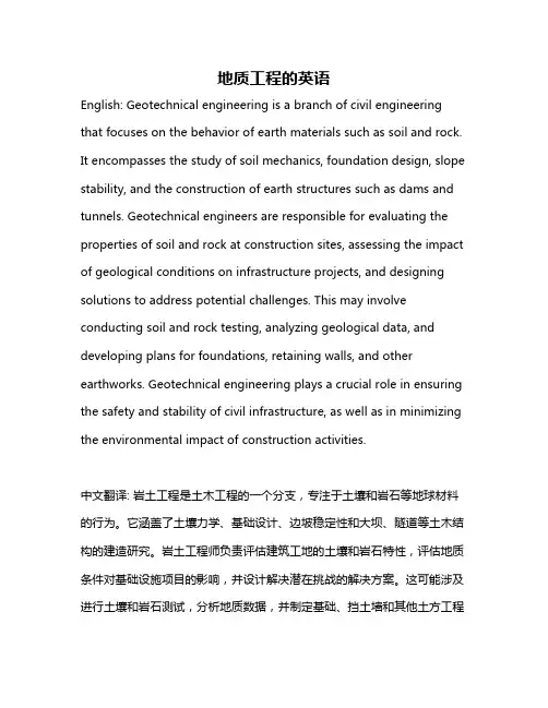
地质工程的英语English: Geotechnical engineering is a branch of civil engineering that focuses on the behavior of earth materials such as soil and rock. It encompasses the study of soil mechanics, foundation design, slope stability, and the construction of earth structures such as dams and tunnels. Geotechnical engineers are responsible for evaluating the properties of soil and rock at construction sites, assessing the impact of geological conditions on infrastructure projects, and designing solutions to address potential challenges. This may involve conducting soil and rock testing, analyzing geological data, and developing plans for foundations, retaining walls, and other earthworks. Geotechnical engineering plays a crucial role in ensuring the safety and stability of civil infrastructure, as well as in minimizing the environmental impact of construction activities.中文翻译: 岩土工程是土木工程的一个分支,专注于土壤和岩石等地球材料的行为。
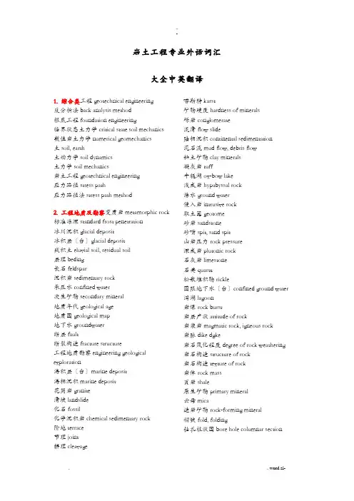
岩土工程专业外语词汇大全中英翻译1. 综合类工程geotechnical engineering反分析法back analysis method根底工程foundation engineering临界状态土力学critical state soil mechanics 数值岩土力学numerical geomechanics土soil, earth土动力学soil dynamics土力学soil mechanics岩土工程geotechnical engineering应力路径stress path应力路径法stress path method2. 工程地质及勘察变质岩metamorphic rock 标准冻深standard frost penetration冰川沉积glacial deposit冰积层〔台〕glacial deposit残积土eluvial soil, residual soil层理beding长石feldspar沉积岩sedimentary rock承压水confined water次生矿物secondary mineral地质年代geological age地质图geological map地下水groundwater断层fault断裂构造fracture structure工程地质勘察engineering geological exploration海积层〔台〕marine deposit海相沉积marine deposit花岗岩granite滑坡landslide化石fossil化学沉积岩chemical sedimentary rock阶地terrace节理joint解理cleavage 喀斯特karst矿物硬度hardness of minerals砾岩conglomerate流滑flow slide陆相沉积continental sedimentation泥石流mud flow, debris flow粘土矿物clay minerals凝灰岩tuff牛轭湖ox-bow lake浅成岩hypabyssal rock潜水ground water侵入岩intrusive rock取土器geotome砂岩sandstone砂嘴spit, sand spit山岩压力rock pressure深成岩plutonic rock石灰岩limestone石英quartz松散堆积物rickle围限地下水〔台〕confined ground water 泻湖lagoon岩爆rock burst岩层产状attitude of rock岩浆岩magmatic rock, igneous rock岩脉dike dgke岩石风化程度degree of rock weathering 岩石构造structure of rock岩石构造texture of rock岩体rock mass页岩shale原生矿物primary mineral云母mica造岩矿物rock-forming mineral褶皱fold, folding钻孔柱状图bore hole columnar section3. 土的分类饱和土saturated soil超固结土overconsolidated soil冲填土dredger fill充重塑土冻土frozen soil, tjaele非饱和土unsaturated soil分散性土dispersive soil粉土silt, mo粉质粘土silty clay高岭石kaolinite过压密土〔台〕overconsolidated soil红粘土red clay, adamic earth黄土loess, huangtu(China)蒙脱石montmorillonite泥炭peat, bog muck年粘土clay年粘性土cohesive soil, clayey soil膨胀土expansive soil, swelling soil欠固结粘土underconsolidated soil区域性土zonal soil人工填土fill, artificial soil软粘土soft clay, mildclay, mickle砂土sand湿陷性黄土collapsible loess, slumping loess 素填土plain fill塑性图plasticity chart碎石土stone, break stone, broken stone, channery, chat, crushed stone, detritus未压密土〔台〕underconsolidated clay无粘性土cohesionless soil, frictional soil, non-cohesive soil岩石rock伊利土illite有机质土organic soil淤泥muck, gyttja, mire, slush淤泥质土mucky soil原状土undisturbed soil杂填土miscellaneous fill正常固结土normally consolidated soil正常压密土〔台〕normally consolidated soil 自重湿陷性黄土self weight collapse loess4. 土的物理性质阿太堡界限Atterberg limits 饱和度degree of saturation饱和密度saturated density 饱和重度saturated unit weight比重specific gravity稠度consistency不均匀系数coefficient of uniformity, uniformity coefficient触变thixotropy单粒构造single-grained structure蜂窝构造honeyb structure干重度dry unit weight干密度dry density塑性指数plasticity index含水量water content, moisture content活性指数activity index级配gradation, grading 结合水bound water, bined water, held water 界限含水量Atterberg limits颗粒级配particle size distribution of soils, mechanical position of soil可塑性plasticity孔隙比void ratio孔隙率porosity粒度granularity, graininess, grainage粒组fraction, size fraction毛细管水capillary water密度density密实度pactionness年粘性土的灵敏度sensitivity of cohesive soil 平均粒径mean diameter, average grain diameter曲率系数coefficient of curvature三相图block diagram, skeletal diagram, three phase diagram三相土tri-phase soil湿陷起始应力initial collapse pressure湿陷系数coefficient of collapsibility缩限shrinkage limit土的构造soil texture土的构造soil structure土粒相对密度specific density of solid particles 土中气air in soil土中水water in soil团粒aggregate cumularpharolith限定粒径constrained diameter相对密度relative density, density index相对压密度relative paction, pacting factor,percent paction, coefficient of paction絮状构造flocculent structure压密系数coefficient of consolidation压缩性pressibility液限liquid limit液性指数liquidity index游离水〔台〕free water有效粒径effective diameter, effective grain size, effective size有效密度effective density有效重度effective unit weight重力密度unit weight自由水free water, gravitational water, groundwater, phreatic water组构fabric最大干密度maximum dry density最优含水量optimum water content5. 渗透性和渗流达西定律Darcy s law管涌piping浸润线phreatic line临界水力梯度critical hydraulic gradient流函数flow function流土flowing soil流网flow net砂沸sand boil渗流seepage渗流量seepage discharge渗流速度seepage velocity渗透力seepage force渗透破坏seepage failure渗透系数coefficient of permeability渗透性permeability势函数potential function水力梯度hydraulic gradient6. 地基应力和变形变形deformation变形模量modulus of deformation泊松比Poisson s ratio布西涅斯克解Boussinnesq s solution剩余变形residual deformation剩余孔隙水压力residual pore water pressure 超静孔隙水压力excess pore water pressure沉降settlement沉降比settlement ratio 次固结沉降secondary consolidation settlement 次固结系数coefficient of secondary consolidation地基沉降的弹性力学公式elastic formula for settlement calculation分层总和法layerwise summation method负孔隙水压力negative pore water pressure附加应力superimposed stress割线模量secant modulus固结沉降consolidation settlement规沉降计算法settlement calculation by specification回弹变形rebound deformation回弹模量modulus of resilience回弹系数coefficient of resilience回弹指数swelling index建筑物的地基变形允许值allowable settlement of building剪胀dilatation角点法corner-points method孔隙气压力pore air pressure孔隙水压力pore water pressure孔隙压力系数Apore pressure parameter A孔隙压力系数Bpore pressure parameter B明德林解Mindlin s solution纽马克感应图Newmark chart切线模量tangent modulus蠕变creep三向变形条件下的固结沉降three-dimensional consolidation settlement瞬时沉降immediate settlement塑性变形plastic deformation弹性变形elastic deformation弹性模量elastic modulus弹性平衡状态state of elastic equilibrium体积变形模量volumetric deformation modulus先期固结压力preconsolidation pressure压缩层pressed layer压缩模量modulus of pressibility压缩系数coefficient of pressibility压缩性pressibility压缩指数pression index有效应力effective stress自重应力self-weight stress总应力total stress approach of shear strength 最终沉降final settlement7. 固结巴隆固结理论Barron s consolidation theory比奥固结理论Biot s consolidation theory超固结比over-consolidation ratio超静孔隙水压力excess pore water pressure 次固结secondary consolidation次压缩〔台〕secondary consolidation单向度压密〔台〕one-dimensional consolidation多维固结multi-dimensional consolidation固结consolidation固结度degree of consolidation固结理论theory of consolidation固结曲线consolidation curve固结速率rate of consolidation固结系数coefficient of consolidation固结压力consolidation pressure回弹曲线rebound curve井径比drain spacing ratio井阻well resistance曼代尔-克雷尔效应Mandel-Cryer effect 潜变〔台〕creep砂井sand drain砂井地基平均固结度average degree of consolidation of sand-drained ground时间对数拟合法logrithm of time fitting method时间因子time factor太沙基固结理论Terzaghi s consolidation theory太沙基-伦杜列克扩散方程Terzaghi-Rendulic diffusion equation先期固结压力preconsolidation pressure压密〔台〕consolidation压密度〔台〕degree of consolidation压缩曲线pression curve一维固结one dimensional consolidation有效应力原理principle of effective stress预压密压力〔台〕preconsolidation pressure 原始压缩曲线virgin pression curve 再压缩曲线repression curve主固结primary consolidation主压密〔台〕primary consolidation准固结压力pseudo-consolidation pressureK0固结consolidation under K0 condition8. 抗剪强度安息角〔台〕angle of repose不排水抗剪强度undrained shear strength剩余摩擦角residual angle of internal friction 剩余强度residual strength长期强度long-term strength单轴抗拉强度uniaxial tension test动强度dynamic strength of soils峰值强度peak strength伏斯列夫参数Hvorslev parameter剪切应变速率shear strain rate抗剪强度shear strength抗剪强度参数shear strength parameter抗剪强度有效应力法effective stress approach of shear strength抗剪强度总应力法total stress approach of shear strength库仑方程Coulomb s equation摩尔包线Mohr s envelope摩尔-库仑理论Mohr-Coulomb theory摩擦角angle of internal friction年粘聚力cohesion破裂角angle of rupture破坏准那么failure criterion十字板抗剪强度vane strength无侧限抗压强度unconfined pression strength 有效摩擦角effective angle of internal friction 有效粘聚力effective cohesion intercept有效应力破坏包线effective stress failure envelope有效应力强度参数effective stress strength parameter有效应力原理principle of effective stress真摩擦角true angle internal friction真粘聚力true cohesion总应力破坏包线total stress failure envelope 总应力强度参数total stress strength parameter9. 本构模型本构模型constitutive model边界面模型boundary surface model层向各向同性体模型cross anisotropic model 超弹性模型hyperelastic model德鲁克-普拉格准那么Drucker-Prager criterion邓肯-模型Duncan-Chang model动剪切强度非线性弹性模量nonlinear elastic model盖帽模型cap model刚塑性模型rigid plastic model割线模量secant modulus广义·米赛斯屈服准那么extended von Mises yield criterion广义特雷斯卡屈服准那么extended tresca yield criterion加工软化work softening加工硬化work hardening加工硬化定律strain harding law剑桥模型Cambridge model柯西弹性模型Cauchy elastic model拉特-邓肯模型Lade-Duncan model拉特屈服准那么Lade yield criterion理想弹塑性模型ideal elastoplastic model临界状态弹塑性模型critical state elastoplastic model流变学模型rheological model流动规那么flow rule摩尔-库仑屈服准那么Mohr-Coulomb yield criterion蕴时间塑性模型endochronic plastic model 蕴时间塑性理论endochronic theory年粘弹性模型viscoelastic model切线模量tangent modulus清华弹塑性模型Tsinghua elastoplastic model 屈服面yield surface珠江三重屈服面模型Shen Zhujiang three yield surface method双参数地基模型双剪应力屈服模型twin shear stress yield criterion双曲线模型hyperbolic model松岗元-中井屈服准那么Matsuoka-Nakai yield criterion塑性形变理论弹塑性模量矩阵elastoplastic modulus matrix弹塑性模型elastoplastic modulus弹塑性增量理论incremental elastoplastic theory弹性半空间地基模型elastic half-space foundation model弹性变形elastic deformation弹性模量elastic modulus弹性模型elastic model汝龙-Khosla-Wu模型WeiRulong-Khosla-Wu model文克尔地基模型Winkler foundation model 修正剑桥模型modified cambridge model准弹性模型hypoelastic model10. 地基承载力冲剪破坏punching shear failure次层〔台〕substratum地基subgrade, ground, foundation soil地基承载力bearing capacity of foundation soil 地基极限承载力ultimate bearing capacity of foundation soil地基允许承载力allowable bearing capacity of foundation soil地基稳定性stability of foundation soil汉森地基承载力公式Hansen s ultimate bearing capacity formula极限平衡状态state of limit equilibrium加州承载比〔美国〕California Bearing Ratio 局部剪切破坏local shear failure临塑荷载critical edge pressure梅耶霍夫极限承载力公式Meyerhof s ultimate bearing capacity formula普朗特承载力理论Prandel bearing capacity theory斯肯普顿极限承载力公式Skempton s ultimate bearing capacity formula太沙基承载力理论Terzaghi bearing capacity theory锡克极限承载力公式Vesic s ultimate bearing capacity formula整体剪切破坏general shear failure11. 土压力被动土压力passive earth pressure 被动土压力系数coefficient of passive earth pressure极限平衡状态state of limit equilibrium静止土压力earth pressure at rest静止土压力系数coefficient of earth pressure at rest库仑土压力理论Coulomb s earth pressure theory库尔曼图解法Culmannn construction朗肯土压力理论Rankine s earth pressure theory朗肯状态Rankine state弹性平衡状态state of elastic equilibrium土压力earth pressure主动土压力active earth pressure主动土压力系数coefficient of active earth pressure12. 土坡稳定分析安息角〔台〕angle of repose 分析毕肖普法Bishop method分析边坡稳定平安系数safety factor of slope 分析不平衡推理传递法unbalanced thrust transmission method分析费伦纽斯条分法Fellenius method of slices分析库尔曼法Culmann method分析摩擦圆法friction circle method分析摩根斯坦-普拉斯法Morgenstern-Price method分析铅直边坡的临界高度critical height of vertical slope分析瑞典圆弧滑动法Swedish circle method 分析斯宾赛法Spencer method分析泰勒法Taylor method分析条分法slice method分析土坡slope分析土坡稳定分析slope stability analysis分析土坡稳定极限分析法limit analysis method of slope stability分析土坡稳定极限平衡法limit equilibrium method of slope stability分析休止角angle of repose分析扬布普遍条分法Janbu general slice method分析圆弧分析法circular arc analysis13. 土的动力性质比阻尼容量specific gravity capacity波的弥散特性dispersion of waves波速法wave velocity method材料阻尼material damping初始液化initial liquefaction地基固有周期natural period of soil site动剪切模量dynamic shear modulus of soils 动力布西涅斯克解dynamic solution of Boussinesq动力放大因素dynamic magnification factor 动力性质dynamic properties of soils动强度dynamic strength of soils骨架波akeleton waves in soils几何阻尼geometric damping抗液化强度liquefaction stress孔隙流体波fluid wave in soil损耗角loss angle往返活动性reciprocating activity无量纲频率dimensionless frequency液化liquefaction液化势评价evaluation of liquefaction potential 液化应力比stress ratio of liquefaction应力波stress waves in soils振陷dynamic settlement阻尼damping of soil阻尼比damping ratio14. 挡土墙挡土墙retaining wall挡土墙排水设施挡土墙稳定性stability of retaining wall垛式挡土墙扶垛式挡土墙counterfort retaining wall后垛墙〔台〕counterfort retaining wall根底墙foundation wall加筋土挡墙reinforced earth bulkhead锚定板挡土墙anchored plate retaining wall锚定式板桩墙anchored sheet pile wall锚杆式挡土墙anchor rod retaining wall悬壁式板桩墙cantilever sheet pile wall悬壁式挡土墙cantilever sheet pile wall重力式挡土墙gravity retaining wall15. 板桩构造物板桩sheet pile物板桩构造sheet pile structure物钢板桩steel sheet pile物钢筋混凝土板桩reinforced concrete sheet pile物钢桩steel pile物灌注桩cast-in-place pile物拉杆tie rod物锚定式板桩墙anchored sheet pile wall物锚固技术anchoring物锚座Anchorage物木板桩wooden sheet pile物木桩timber piles物悬壁式板桩墙cantilever sheet pile wall16. 基坑开挖与降水板桩围护sheetpile-braced cuts电渗法electro-osmotic drainage管涌piping基底隆起heave of base基坑降水dewatering基坑失稳instability (failure) of foundation pit 基坑围护bracing of foundation pit减压井relief well降低地下水位法dewatering method井点系统well point system喷射井点eductor well point铅直边坡的临界高度critical height of vertical slope砂沸sand boiling深井点deep well point真空井点vacuum well point支撑围护braced cuts17. 浅根底补偿性根底pensated foundation 持力层bearing stratum次层〔台〕substratum单独根底individual footing倒梁法inverted beam method刚性角pressure distribution angle of masonary foundation 刚性根底rigid foundation高杯口根底根底埋置深度embeded depth of foundation基床系数coefficient of subgrade reaction基底附加应力net foundation pressure穿插条形根底cross strip footing接触压力contact pressure静定分析法〔浅根底〕static analysis (shallow foundation)壳体根底shell foundation扩展根底spread footing片筏根底mat foundation浅根底shallow foundation墙下条形根底热摩奇金法Zemochkin s method柔性根底flexible foundation上部构造-根底-土共同作用分析structure- foundation-soil interactionanalysis弹性地基梁〔板〕分析analysis of beams and slabs on elastic foundation条形根底strip footing下卧层substratum箱形根底box foundation18. 深根底贝诺托灌注桩Benoto cast-in-place pile波动方程分析Wave equation analysis场铸桩〔台)cast-in-place pile沉管灌注桩diving casting cast-in-place pile沉井根底open-end caisson foundation沉箱根底box caisson foundation成孔灌注同步桩synchronous pile承台pile caps充盈系数fullness coefficient单桩承载力bearing capacity of single pile单桩横向极限承载力ultimate lateral resistance of single pile单桩竖向抗拔极限承载力vertical ultimate uplift resistance of single pile单桩竖向抗压容许承载力vertical ultimate carrying capacity of single pile单桩竖向抗压极限承载力vertical allowable load capacity of single pile低桩承台low pile cap地下连续墙diaphgram wall点承桩〔台〕end-bearing pile动力打桩公式dynamic pile driving formula 端承桩end-bearing pile法兰基灌注桩Franki pile负摩擦力negative skin friction of pile钢筋混凝土预制桩precast reinforced concrete piles钢桩steel pile高桩承台high-rise pile cap灌注桩cast-in-place pile横向载荷桩laterally loaded vertical piles护壁泥浆slurry coat method回转钻孔灌注桩rotatory boring cast-in-place pile静力压桩silent piling抗拔桩uplift pile抗滑桩anti-slide pile摩擦桩friction pile木桩timber piles嵌岩灌注桩piles set into rock群桩pile groups群桩效率系数efficiency factor of pile groups 群桩效应efficiency of pile groups群桩竖向极限承载力vertical ultimate load capacity of pile groups深根底deep foundation竖直群桩横向极限承载力无桩靴夯扩灌注桩rammed bulb ile桩piles桩基动测技术dynamic pile test钻孔墩根底drilled-pier foundation钻孔扩底灌注桩under-reamed bored pile钻孔压注桩starsol enbesol pile最后贯入度final set19. 地基处理表层压密法surface paction超载预压surcharge preloading袋装砂井sand wick地工织物geofabric, geotextile地基处理ground treatment, foundation treatment电动化学灌浆electrochemical grouting电渗法electro-osmotic drainage 顶升纠偏法定喷directional jet grouting冻土地基处理frozen foundation improvement 短桩处理treatment with short pile堆载预压法preloading粉体喷射深层搅拌法powder deep mixing method复合地基posite foundation干振成孔灌注桩vibratory bored pile高压喷射注浆法jet grouting灌浆材料injection material灌浆法grouting硅化法silicification夯实桩pacting pile化学灌浆chemical grouting换填法cushion灰土桩lime soil pile挤密灌浆paction grouting挤密桩paction pile, pacted column挤淤法displacement method加筋法reinforcement method加筋土reinforced earth碱液法soda solution grouting浆液深层搅拌法grout deep mixing method 降低地下水位法dewatering method坑式托换pit underpinning冷热处理法freezing and heating锚固技术anchoring锚杆静压桩托换anchor pile underpinning排水固结法consolidation膨胀土地基处理expansive foundation treatment劈裂灌浆fracture grouting浅层处理shallow treatment强夯法dynamic paction人工地基artificial foundation容许灌浆压力allowable grouting pressure褥垫pillow软土地基soft clay ground砂井sand drain砂井地基平均固结度average degree of consolidation of sand-drained ground砂桩sand column山区地基处理foundation treatment in mountain area深层搅拌法deep mixing method渗入性灌浆seep-in grouting湿陷性黄土地基处理collapsible loess treatment石灰系深层搅拌法lime deep mixing method 石灰桩lime column, limepile树根桩root pile水泥土水泥掺合比cement mixing ratio水泥系深层搅拌法cement deep mixing method水平旋喷horizontal jet grouting塑料排水带plastic drain碎石桩gravel pile, stone pillar天然地基natural foundation土工聚合物Geopolymer土工织物geofabric, geotextile土桩earth pile托换技术underpinning technique外掺剂additive旋喷jet grouting药液灌浆chemical grouting预浸水法presoaking预压法preloading真空预压vacuum preloading振冲法vibroflotation method振冲密实法vibro-paction振冲碎石桩vibro replacement stone column 振冲置换法vibro-replacement振密、挤密法vibro-densification, pacting置换率〔复合地基〕replacement ratio重锤夯实法tamping桩式托换pile underpinning桩土应力比stress ratio20. 动力机器根底比阻尼容量specific gravity capacity等效集总参数法constant strain rate consolidation test地基固有周期natural period of soil site动基床反力法dynamic subgrade reaction method动力放大因素dynamic magnification factor 隔振isolation根底振动foundation vibration 根底振动半空间理论elastic half-space theory of foundation vibration根底振动容许振幅allowable amplitude of foundation vibration根底自振频率natural frequency of foundation 集总参数法lumped parameter method吸收系数absorption coefficient质量-弹簧-阻尼器系统mass-spring-dushpot system21. 地基根底抗震地基固有周期natural period of soil site地震earthquake, seism, temblor地震持续时间duration of earthquake地震等效均匀剪应力equivalent even shear stress of earthquake地震反响谱earthquake response spectrum地震烈度earthquake intensity地震震级earthquake magnitude地震卓越周期seismic predominant period地震最大加速度maximum acceleration of earthquake动力放大因数dynamic magnification factor 对数递减率logrithmic decrement刚性系数coefficient of rigidity吸收系数absorption coefficient22. 室土工试验比重试验specific gravity test 变水头渗透试验falling head permeability test 不固结不排水试验unconsolidated-undrained triaxial test常规固结试验routine consolidation test常水头渗透试验constant head permeability test单剪仪simple shear apparatus单轴拉伸试验uniaxial tensile test等速加荷固结试验constant loading rate consolidation test等梯度固结试验constant gradient consolidation test等应变速率固结试验equivalent lumped parameter method反复直剪强度试验repeated direct shear test 反压饱和法back pressure saturation method高压固结试验high pressure consolidation test 各向不等压固结不排水试验consoidated anisotropically undrained test各向不等压固结排水试验consolidated anisotropically drained test共振柱试验resonant column test固结不排水试验consolidated undrained triaxial test固结快剪试验consolidated quick direct shear test固结排水试验consolidated drained triaxial test 固结试验consolidation test含水量试验water content test环剪试验ring shear test黄土湿陷试验loess collapsibility test界限含水量试验Atterberg limits test卡萨格兰德法Casagrande s method颗粒分析试验grain size analysis test孔隙水压力消散试验pore pressure dissipation test快剪试验quick direct shear test快速固结试验fast consolidation test离心模型试验centrifugal model test连续加荷固结试验continual loading test慢剪试验consolidated drained direct shear test 毛细管上升高度试验capillary rise test密度试验density test扭剪仪torsion shear apparatus膨胀率试验swelling rate test平面应变仪plane strain apparatus三轴伸长试验triaxial extension test三轴压缩试验triaxial pression test砂的相对密实度试验sand relative density test 筛分析sieve analysis渗透试验permeability test湿化试验slaking test收缩试验shrinkage test塑限试验plastic limit test缩限试验shrinkage limit test土工模型试验geotechnical model test土工织物试验geotextile test无侧限抗压强度试验unconfined pression strength test无粘性土天然坡角试验angle of repose of cohesionless soils test压密不排水三轴压缩试验consolidated undrained triaxial pression test压密排水三轴压缩试验consolidated drained triaxial pressure test压密试验consolidation test液塑限联合测定法liquid-plastic limit bined method液限试验liquid limit test应变控制式三轴压缩仪strain control triaxial pression apparatus应力控制式三轴压缩仪stress control triaxial pression apparatus有机质含量试验organic matter content test 真三轴仪true triaxial apparatus振动单剪试验dynamic simple shear test直剪仪direct shear apparatus直接剪切试验direct shear test直接单剪试验direct simple shear test自振柱试验free vibration column testK0固结不排水试验K0 consolidated undrained testK0固结排水试验K0 consolidated drained test23. 原位测试标准贯入试验standard penetration test外表波试验surface wave test超声波试验ultrasonic wave test承载比试验Califonia Bearing Ratio Test单桩横向载荷试验lateral load test of pile单桩竖向静载荷试验static load test of pile 动力触探试验dynamic penetration test静力触探试验static cone penetration test静力载荷试验plate loading test跨孔试验cross-hole test块体共振试验block resonant test螺旋板载荷试验screw plate test旁压试验pressurementer test轻便触探试验light sounding test深层沉降观测deep settlement measurement 十字板剪切试验vane shear test无损检测nondestructive testing..-下孔法试验down-hole test现场渗透试验field permeability test原位孔隙水压力量测in situ pore waterpressure measurement原位试验in-situ soil test最后贯入度final set. . word.zl-。
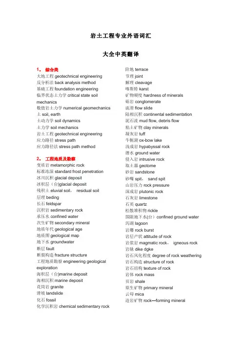
岩土工程专业外语词汇大全中英翻译1。
综合类大地工程geotechnical engineering反分析法back analysis method基础工程foundation engineering临界状态土力学critical state soil mechanics数值岩土力学numerical geomechanics 土soil, earth土动力学soil dynamics土力学soil mechanics岩土工程geotechnical engineering应力路径stress path应力路径法stress path method2。
工程地质及勘察变质岩metamorphic rock标准冻深standard frost penetration冰川沉积glacial deposit冰积层(台)glacial deposit残积土eluvial soil,residual soil层理beding长石feldspar沉积岩sedimentary rock承压水confined water次生矿物secondary mineral地质年代geological age地质图geological map地下水groundwater断层fault断裂构造fracture structure工程地质勘察engineering geological exploration海积层(台)marine deposit海相沉积marine deposit花岗岩granite滑坡landslide化石fossil化学沉积岩chemical sedimentary rock 阶地terrace节理joint解理cleavage喀斯特karst矿物硬度hardness of minerals砾岩conglomerate流滑flow slide陆相沉积continental sedimentation泥石流mud flow, debris flow粘土矿物clay minerals凝灰岩tuff牛轭湖ox-bow lake浅成岩hypabyssal rock潜水ground water侵入岩intrusive rock取土器geotome砂岩sandstone砂嘴spit,sand spit山岩压力rock pressure深成岩plutonic rock石灰岩limestone石英quartz松散堆积物rickle围限地下水(台)confined ground water 泻湖lagoon岩爆rock burst岩层产状attitude of rock岩浆岩magmatic rock,igneous rock 岩脉dike dgke岩石风化程度degree of rock weathering 岩石构造structure of rock岩石结构texture of rock岩体rock mass页岩shale原生矿物primary mineral云母mica造岩矿物rock—forming mineral褶皱fold,folding钻孔柱状图bore hole columnar section3. 土的分类饱和土saturated soil超固结土overconsolidated soil冲填土dredger fill充重塑土冻土frozen soil,tjaele非饱和土unsaturated soil分散性土dispersive soil粉土silt, mo粉质粘土silty clay高岭石kaolinite过压密土(台)overconsolidated soil红粘土red clay, adamic earth黄土loess,huangtu(China)蒙脱石montmorillonite泥炭peat,bog muck年粘土clay年粘性土cohesive soil,clayey soil膨胀土expansive soil, swelling soil欠固结粘土underconsolidated soil区域性土zonal soil人工填土fill,artificial soil软粘土soft clay, mildclay,mickle砂土sand湿陷性黄土collapsible loess, slumping loess素填土plain fill塑性图plasticity chart碎石土stone, break stone,broken stone, channery,chat, crushed stone, detritus 未压密土(台)underconsolidated clay无粘性土cohesionless soil,frictional soil, non—cohesive soil岩石rock伊利土illite有机质土organic soil淤泥muck,gyttja,mire, slush淤泥质土mucky soil原状土undisturbed soil杂填土miscellaneous fill正常固结土normally consolidated soil 正常压密土(台)normally consolidated soil 自重湿陷性黄土self weight collapse loess4. 土的物理性质阿太堡界限Atterberg limits饱和度degree of saturation饱和密度saturated density饱和重度saturated unit weight比重specific gravity稠度consistency不均匀系数coefficient of uniformity,uniformity coefficient触变thixotropy单粒结构single-grained structure蜂窝结构honeycomb structure干重度dry unit weight干密度dry density塑性指数plasticity index含水量water content, moisture content活性指数activity index级配gradation,grading结合水bound water,combined water,held water界限含水量Atterberg limits颗粒级配particle size distribution of soils,mechanical composition of soil可塑性plasticity孔隙比void ratio孔隙率porosity粒度granularity, graininess,grainage粒组fraction, size fraction毛细管水capillary water密度density密实度compactionness年粘性土的灵敏度sensitivity of cohesive soil平均粒径mean diameter,average grain diameter曲率系数coefficient of curvature三相图block diagram, skeletal diagram, three phase diagram三相土tri—phase soil湿陷起始应力initial collapse pressure湿陷系数coefficient of collapsibility缩限shrinkage limit土的构造soil texture土的结构soil structure土粒相对密度specific density of solid particles土中气air in soil土中水water in soil团粒aggregate cumularpharolith限定粒径constrained diameter相对密度relative density,density index 相对压密度relative compaction,compacting factor, percent compaction,coefficient of compaction絮状结构flocculent structure压密系数coefficient of consolidation压缩性compressibility液限liquid limit液性指数liquidity index游离水(台)free water有效粒径effective diameter, effective grain size, effective size有效密度effective density有效重度effective unit weight重力密度unit weight自由水free water,gravitational water, groundwater, phreatic water组构fabric最大干密度maximum dry density最优含水量optimum water content5. 渗透性和渗流达西定律Darcy s law管涌piping浸润线phreatic line临界水力梯度critical hydraulic gradient流函数flow function流土flowing soil流网flow net砂沸sand boil渗流seepage渗流量seepage discharge渗流速度seepage velocity渗透力seepage force渗透破坏seepage failure 渗透系数coefficient of permeability渗透性permeability势函数potential function水力梯度hydraulic gradient6. 地基应力和变形变形deformation变形模量modulus of deformation泊松比Poisson s ratio布西涅斯克解Boussinnesq s solution残余变形residual deformation残余孔隙水压力residual pore water pressure超静孔隙水压力excess pore water pressure沉降settlement沉降比settlement ratio次固结沉降secondary consolidation settlement次固结系数coefficient of secondary consolidation地基沉降的弹性力学公式elastic formula for settlement calculation分层总和法layerwise summation method 负孔隙水压力negative pore water pressure附加应力superimposed stress割线模量secant modulus固结沉降consolidation settlement规范沉降计算法settlement calculation by specification回弹变形rebound deformation回弹模量modulus of resilience回弹系数coefficient of resilience回弹指数swelling index建筑物的地基变形允许值allowable settlement of building剪胀dilatation角点法corner-points method孔隙气压力pore air pressure孔隙水压力pore water pressure孔隙压力系数Apore pressure parameter A 孔隙压力系数Bpore pressure parameter B 明德林解Mindlin s solution纽马克感应图Newmark chart切线模量tangent modulus蠕变creep三向变形条件下的固结沉降three—dimensional consolidation settlement瞬时沉降immediate settlement塑性变形plastic deformation弹性变形elastic deformation弹性模量elastic modulus弹性平衡状态state of elastic equilibrium 体积变形模量volumetric deformation modulus先期固结压力preconsolidation pressure 压缩层compressed layer压缩模量modulus of compressibility压缩系数coefficient of compressibility压缩性compressibility压缩指数compression index有效应力effective stress自重应力self—weight stress总应力total stress approach of shear strength最终沉降final settlement7。
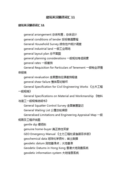
建筑英汉翻译词汇11建筑英汉翻译词汇11general arrangement 总体布置;总体设计general conditions of tender 投标普通章程General Household Survey 综合住户统计调查general industrial land 一般工业用地general layout plan 总平面图general planning considerations 一般规划考虑因素general rates 一般差饷General Requisition for Particulars of Tenement 一般物业详情申报表general revaluation 全面重估应课差饷租值general shear failure 整体剪切破坏General Specification for Civil Engineering Works 《土木工程一般规格》General Specifications on Material and Workmanship 《物料与造工一般规格说明书》General Squatter Control Survey 全面寮屋登记General Waiting List 公屋总轮候册Generalised Limitations and Engineering Appraisal Map 一般规限及工程评估图gentle dip 缓倾斜genuine home-buyer 真正自住买家GEO Emergency Manual 《土力工程处紧急服务手册》geochemical data 地球化学资料;岩土数据geodetic datum 测地基准点;大地基准Geodetic Datums in Hong Kong 香港大地测量系统geodetic information system 大地信息系统Geodetic Section [Lands Department] 大地测量组〔地政总署〕geodetic survey 大地测量Geodetic Survey Information System 大地测量信息系统Geographic Place Names Board 地名订正委员会geographic reference system 定位查照系统geographical co-ordinate system 地理坐标系统geographical information system 地理信息系统geographical mapping 地理勘察;地理测绘geographical zone 地理分区geogrid 土工格杉geoid 大地水准面geological condition 地质状况geological data computer system 地质资料电脑系统geological map 地质图geological mapping 地质勘察;地质测绘geological memoir 地质报告geological profile 地质剖面geological survey 地质调查geological survey memoir 地质调查报告geological survey plan 地质调查图Geology Society of Hong Kong 香港地质学会geomancer 堪舆师geomembrane 土工膜;隔泥网膜geomorphologic map 地貌图geomorphology 地貌学geophysical exploration 地球物理勘探geophysical survey 地球物理测量geoscience database 地质科学资料库geostatic stress 地应力geosynthetics 土工合成材料geotechnical 岩土;土力geotechnical appraisal 岩土评估;土力评估Geotechnical Area Study Programme 地区岩土研究计划geotechnical assessment 岩土评估;土力评估geotechnical assessment study 岩土评估研究;土力评估研究geotechnical consultant 岩土工程顾问;土力工程顾问geotechnical control 岩土工程管制geotechnical data 岩土数据geotechnical design 岩土工程设计geotechnical design assumption 岩土设计假定Geotechnical Engineer 土力工程师Geotechnical Engineering Office [Civil Engineering Department] 土力工程处〔土木工程署〕geotechnical information unit [Civil Engineering Department] 岩土工程资料库〔土木工程署〕geotechnical investigation 岩土工程勘察;岩土工程勘探Geotechnical Land Use Map 岩土分析土地用途图Geotechnical Manual for Slopes 《斜坡岩土工程手册》geotechnical record 岩土记录geotechnical specialist 岩土工程专家geotechnical study 岩土工程调查;岩土工程研究geotechnical survey 土力测量geotechnically difficult site 有土力问题的建屋地盘geotextile 土工织物;隔泥纺织物料geyser 热水器Gini Coefficient 坚尼系数girder 主梁;大梁glaciation 冰蚀现象;冰川作用gland 封头;压盖glass block screen wall 玻璃幕墙glass bulb 玻璃泡glass fibre insulator 玻璃纤维绝缘器glass louvre 玻璃百叶窗glass mosaic tile 玻璃纸皮石;玻璃锦砖glass panel 玻璃嵌板glass reinforced concrete 玻璃纤维混凝土glass reinforced plastic pipe 玻璃强化胶管glass tile 玻璃砖glaze 装嵌玻璃片glazed brick 釉面砖glazed ceramic tile 釉面瓷砖glazed earthenware 釉面陶土glazed mosaic tile 釉面纸皮石glazed porcelain 玻璃瓷glazed tile 瓷砖;玻璃砖;釉面瓦glazed wall tile 墙壁瓷砖glazed ware 釉面物料glazier 玻璃工glazing bead 玻璃压条glazing compound 镶玻璃油灰glazing gasket 玻璃封边;玻璃镶边glazing works 装配玻璃工程Global Co-ordinate System 全球坐标系统global factor of safety 综合安全系数Global Positioning System [GPS] 全球卫星定位系统global stability problem 整体稳定性问题gloss paint 光油gneiss 片麻岩gondola 吊船工作台;吊船good title 妥善业权goods lift 载货升降机Government Chainmen Union 政府丈量员职工会government contractor 政府承建商government conveyancing 政府产权转易Government Engineer 政府工程师government grant 政府批地书government housing 政府房屋government land 政府土地Government Land Agent 政府地政监督government land allocation 政府拨地government land bank 政府储备土地Government Land Licence [GLL] 政府土地租用牌照Government Land Permit 政府土地租用许可证Government lease [formerly known as Crown lease] 政府租契〔前称官契〕Government lessee 政府土地承租人;政府土地承批人Government Local Civil Engineer’s Association 政府非海外土木工程师协会government low-cost housing estate 政府廉租屋government main 政府水喉总管Government Procurement Agreement 政府采购协议Government Property Administrator 政府产业署署长Government Property Agency 政府产业署government public works 政府公共工程government quarters 政府宿舍Government rent [formerly known as Crown rent] 地税Government Rent Collection Section [Lands Department] 地租追缴组〔地政总署〕Government Rent Demand Note 缴纳地税通知书Government Rent Reminder 催缴地税通知书Government Rent Roll 地税册Government rights [formerly known as Crown rights] 政府土地权〔前称官地权〕government slope 政府斜坡government use 政府用途government-aided housing 政府助建屋宇government-assisted housing project 政府资助建屋计划government/institution/community area 政府/团体/社区用地government/institution/community facility 政府/团体/社区用地设施government/institution/community use 政府/团体/社区用途government/institution/community zone 政府/团体/社区分区government-owned quarters 政府所拥有的宿舍grab dredger 抓斗式挖泥船grade strength 等级强度graded shop 分级铺位grader 平土机gradient 斜度;坡度grading analysis [soil] 级配分析;颗粒分析〔泥土〕grading curve 粒径分布曲线grain size 粒径grand summary to the bills of quantities 建筑工料清单摘要granite 花岗岩;花岗石granite chipping 花岗岩屑granite face 花岗岩面层;花岗岩砌面granite sett 小方块花岗岩granite tile 花岗岩砖granitic rock 花岗质岩石granodiorite 花岗闪长岩granolithic 石米granolithic finish 人造石铺面granolithic paving 人造铺地石granolithic paving finish 人造石铺面granolithic plaster 石米抹面;石米批荡grant conditions 批地条件;批地规约grant of land 批地grantee 承批人;承授人grantor 授予人granular 颗粒状的granular bedding [road] 路碎石层granular material 颗粒材graphite mould 石墨模子grass seed 草种grass seed mix 混合草种grass sod 草皮;方块草皮grass sprig 草苗grass sward 草层grass verge 植草路旁带grassland 草地grating 格栅;渠闸grating cover 格栅盖grave claimant 祖坟认领人grave compensation 墓地补偿gravel 砾石;卵石gravel pack 填砾gravelly sand 砾砂gravity core 重力取样gravity corer 重力式取样管gravity cover 重力覆盖gravity dam 重力坝gravity flow sewer 引力污水渠;无压污水渠gravity load 重力荷载gravity sewer system 引力污水渠系统gravity structure 重力式结构gravity type seawall 重力式海堤gravity water supply 天然水压供水;重力供水grease tank 隔油井grease trap 隔油池;隔油缸;“油隔”great lake rock 太湖石Green Card Scheme 平安卡计划green concrete 新浇混凝土;新拌混凝土;生混凝土green form 绿表green form applicant 绿表申请人Green Form Certificate 绿表资格证明书Green Form Certificate holder 绿表资格证明书持有人green link 绿化区Green Paper on Housing Subsidy to Tenants of Public Housing 《公屋住户房屋资助问题绿皮书》green wedge 楔形绿化地带greenfield centre [Type B Commercial Centre] 新发展区商场〔乙类商场〕grid 坐标网;方格网grid data 坐标网数据grid line 坐标线;网格线;分隔条grid of steel bars 钢条板grid system 坐标制;方格网制grill 烤炉grillage foundation 格排基础;格排地基grille 格栅;栏栅grille bar 栏栅铁枝grille block 通花砖grille panel 通花砖墙grille wall 通花砖墙grip length 握固长度grit 砂砾;砂粒grit removal 除砂grooved tile 槽纹瓷砖gross development value 总发展价值gross floor area [GFA] 楼面总面积;建筑楼面面积gross person space [temporary housing area] 总人位〔临时房屋区〕gross site area 地盘总面积gross weight 总重量;毛重ground anchor 地锚;地锚桩基ground bay 地下单位ground beam 地梁ground bearing pressure 地面承载力ground clearance 离地净高ground condition 土地状况;地面条件ground cover 铺地植物ground engineering 地基工程ground feature 地物;地貌ground floor 地下ground floor arcade 地下商场ground floor level 地面层水平ground floor shop 地下铺位ground improvement works 地面改善工程ground investigation 土地勘测;土地勘探;探土ground investigation field work [public works category] 现场勘探工程〔公共工程类别〕ground level 地面;地面水平;地面标高ground level contour 地面水平等高线ground level road 地面道路ground line 地平线ground movement 地面移动;地层移动ground pressure 地面压力ground profile 地形;地形剖面;地形切面ground rent 地租ground row light 地脚排灯ground settlement 土地沉降;地陷ground staff [Home Ownership Scheme] 派驻各屋苑职员〔居者有其屋计划〕ground stress 地应力ground surface 地面ground survey 地面测量ground survey method 地面测量法ground treatment works 土地处理工程;地层处理工程ground-breaking ceremony 动土礼ground-bus 接地母线grounding electrode 接地电极grounds for recovery of possession 收回管有的理由;收回楼宇理由groundwater 地下水groundwater catchment 地下水流域groundwater condition 地下水条件;地下水情况groundwater connectivity test 地下水连通实验groundwater depletion 地下水量枯竭groundwater discharge 地下水流量;地下水溢流groundwater divide 地下水分水岭groundwater drainage works 地下水排水工程groundwater flow direction 地下水流向groundwater level 地下水位groundwater monitoring 地下水监测groundwater pollution 地下水污染groundwater pressure measurement 地下水水压测试groundwater regime 地下水体系groundwater table 地下水位groundwater table fluctuation 地下水位变动Group A estate 甲类屋Group B estate 乙类屋group reduction factor [pile group] 桩组折减系数grout 水泥浆;薄浆;灌浆grout curtain 薄浆隔墙grout mix 薄浆混合料grout pipe 灌浆管grout tube 灌浆管grout vent pipe 灌浆排气管grout-bleeding 薄浆渗出;薄浆浮水grout-bleeding and free expansion 薄浆渗出及自由扩大grout-flow cone efflux time 薄浆流度锥流出时间grouting 灌浆grouting works 灌浆工程guard 护卫员;守卫guard kiosk 更亭guardhouse 护卫员室;警卫室Guidance Notes for Persons Applying for the Incorporation of an Owners Corporation at the Land Registry 《向土地注册处申请成立业主法团人士须知》Guidance Notes for the General Specification for Civil Engineering Works 《土木工程一般规格指引》guide pile 导桩Guide to Cavern Engineering [Geoguide 4] 《岩洞工程指南》〔《岩土指南》第四册〕Guide to Concord 1 Block 《康和一型大厦指南》Guide to Concord 2 Block 《康和二型大厦指南》Guide to Flexi-schools 《弹性十字型校舍指南》Guide to Harmony 1 Block 《和谐一型大厦指南》Guide to Harmony 2 Block 《和谐二型大厦指南》Guide to Harmony 3 Block 《和谐三型大厦指南》Guide to New Cruciform Block 《新十字型大厦指南》Guide to New Standard Schools 《新标准校舍指南》Guide to Retaining Wall Design [Geoguide 1] 《挡土墙设计指南》〔《岩土指南》第一册〕Guide to Rock and Soil Descri ptions [Geoguide 3] 《岩土描述指南》〔《岩土指南》第三册〕Guide to Site Investigation [Geoguide 2] 《场地勘察指南》〔《岩土指南》第二册〕Guide to Slope Maintenance [Geoguide 5] 《斜坡维修指南》〔《岩土指南》第五册〕Guide to Small Households Developments 《小单位发展计划指南》。
PA VEMENT PROBLEMS CAUSEDBY COLLAPSIBLE SUBGRADESBy Sandra L. Houston,1 Associate Member, ASCE(Reviewed by the Highway Division)ABSTRACT: Problem subgrade materials consisting of collapsible soils are com- mon in arid environments, which have climatic conditions and depositional and weathering processes favorable to their formation. Included herein is a discussion of predictive techniques that use commonly available laboratory equipment and testing methods for obtaining reliable estimates of the volume change for these problem soils. A method for predicting relevant stresses and corresponding collapse strains for typical pavement subgrades is presented. Relatively simple methods of evaluating potential volume change, based on results of familiar laboratory tests, are used.INTRODUCTIONWhen a soil is given free access to water, it may decrease in volume,increase in volume, or do nothing. A soil that increases in volume is calleda swelling or expansive soil, and a soil that decreases in volume is called a collapsible soil. The amount of volume change that occurs depends on thesoil type and structure, the initial soil density, the imposed stress state, andthe degree and extent of wetting. Subgrade materials comprised of soils that change volume upon wetting have caused distress to highways since the be- ginning of the professional practice and have cost many millions of dollarsin roadway repairs. The prediction of the volume changes that may occur inthe field is the first step in making an economic decision for dealing withthese problem subgrade materials.Each project will have different design considerations, economic con-straints, and risk factors that will have to be taken into account. However,with a reliable method for making volume change predictions, the best design relative to the subgrade soils becomes a matter of economic comparison, anda much more rational design approach may be made. For example, typical techniques for dealing with expansive clays include: (1) In situ treatmentswith substances such as lime, cement, or fly-ash; (2) seepage barriers and/or drainage systems; or (3) a computing of the serviceability loss and a mod- ification of the design to "accept" the anticipated expansion. In order to makethe most economical decision, the amount of volume change (especially non- uniform volume change) must be accurately estimated, and the degree of road roughness evaluated from these data. Similarly, alternative design techniquesare available for any roadway problem.The emphasis here will be placed on presenting economical and simplemethods for: (1) Determining whether the subgrade materials are collapsible;and (2) estimating the amount of volume change that is likely to occur in the'Asst. Prof., Ctr. for Advanced Res. in Transp., Arizona State Univ., Tempe, AZ 85287.Note. Discussion open until April 1, 1989. To extend the closing date one month,a written request must be filed with the ASCE Manager of Journals. The manuscript for this paper was submitted for review and possible publication on February 3, 1988. This paper is part of the Journal of Transportation.Engineering, V ol. 114, No. 6, November, 1988. ASCE, ISSN 0733-947X/88/0006-0673/$1.00 + $.15 per page. Paper No. 22902.673field for the collapsible soils. Then this information will place the engineerin a position to make a rational design decision. Collapsible soils are fre-quently encountered in an arid climate. The depositional process and for-mation of these soils, and methods for identification and evaluation of theamount of volume change that may occur, will be discussed in the following sections.COLLAPSIBLE SOILSFormation of Collapsible SoilsCollapsible soils have high void ratios and low densities and are typically cohesionless or only slightly cohesive. In an arid climate, evaporation greatly exceeds rainfall. Consequently, only the near-surface soils become wettedfrom normal rainfall. It is the combination of the depositional process andthe climate conditions that leads to the formation of the collapsible soil.Although collapsible soils exist in nondesert regions, the dry environment inwhich evaporation exceeds precipitation is very favorable for the formationof the collapsible structure.As the soil dries by evaporation, capillary tension causes the remainingwater to withdraw into the soil grain interfaces, bringing with it soluble salts,clay, and silt particles. As the soil continues to dry, these salts, clays, andsilts come out of solution, and "tack-weld" the larger grains together. Thisleads to a soil structure that has high apparent strength at its low, naturalwater content. However, collapse of the "cemented" structure may occurupon wetting because the bonding material weakens and softens, and the soilis unstable at any stress level that exceeds that at which the soil had been previously wetted. Thus, if the amount of water made available to the soilis increased above that which naturally exists, collapse can occur at fairlylow levels of stress, equivalent only to overburden soil pressure. Additionalloads, such as traffic loading or the presence of a bridge structure, add tothe collapse, especially of shallow collapsible soil. The triggering mechanismfor collapse, however, is the addition of water.Highway Problems Resulting from Collapsible SoilsNonuniform collapse can result from either a nonhomogeneous subgradedeposit in which differing degrees of collapse potential exist and/or from nonuniform wetting of subgrade materials. When differential collapse ofsubgrade soils occurs, the result is a rough, wavy surface, and potentiallymany miles of extensively damaged highway. There have been several re-ported cases for which differential collapse has been cited as the cause of roadway or highway bridge distress. A few of these in the Arizona and New Mexico region include sections of 1-10 near Benson, Arizona, and sectionsof 1-25 in the vicinity of Algadonas, New Mexico (Lovelace et al. 1982; Russman 1987). In addition to the excessive waviness of the roadway sur- face, bridge foundations failures, such as the Steins Pass Highway bridge,1-10, in Arizona, have frequently been identified with collapse of foundation soils.Identification of Collapsible SoilsThere have been many techniques proposed for identifying a collapsiblesoil problem. These methods range from qualitative index tests conducted on674disturbed samples, to response to wetting tests conducted on relatively un- disturbed samples, to in situ meausrement techniques. In all cases, the en- gineer must first know if the soils may become wetted to a water content above their natural moisture state, and if so, what the extent of the potential wetted zone will be. Most methods for identifying collapsible soils are only qualitative in nature, providing no information on the magnitude of the col- lapse strain potential. These qualitative methods are based on various func- tions of dry density, moisture content, void ratio, specific gravity, and At- terberg limits.In situ measurement methods appear promising in some cases, in that many researchers feel that sample disturbance is greatly reduced, and that a more nearly quantitative measure of collapse potential is obtainable. However,in situ test methods for collapsible soils typically suffer from the deficien-cy of an unknown extent and degree of wetting during the field test. This makes a quantitative measurement difficult because the zone of material being influenced is not well-known, and, therefore, the actual strains, in- duced by the addition of stress and water, are not well-known. In addition, the degree of saturation achieved in the field test is variable and usually unknown.Based on recently conducted research, it appears that the most reliable method for identifying a collapsible soil problem is to obtain the best quality undisturbed sample possible and to subject this sample to a response to wet- ting test in the laboratory. The results of a simple oedometer test will indicate whether the soil is collapsible and, at the same time, give a direct measureof the amount of collapse strain potential that may occur in the field. Potential problems associated with the direct sampling method include sample distur- bance and the possibility that the degree of saturation achieved in the field will be less than that achieved in the laboratory test.The quality of an undisturbed sample is related most strongly to the arearatio of the tube that is used for sample collection. The area ratio is a measure of the ratio of the cross-sectional area of the sample collected to the cross- sectional area of the sample tube. A thin-walled tube sampler by definition has an area ratio of about 10-15%. Although undisturbed samples are best obtained through the use of thin-walled tube samplers, it frequently occurs that these stiff, cemented collapsible soils, especially those containing gravel, cannot be sampled unless a tube with a much thicker wall is used. Samplers having an area ratio as great as 56% are commonly used for Arizona col- lapsible soils. Further, it may take considerable hammering of the tube to drive the sample. The result is, of course, some degree of sample distur- bance, broken.bonds, densification, and a correspondingly reduced collapse measured upon laboratory testing. However, for collapsible soils, which are compressive by definition, the insertion of the sample tube leads to local shear failure at the base of the cutting edge, and, therefore, there is less sample disturbance than would be expected for soils that exhibit general shear failure (i.e., saturated clays or dilative soils). Results of an ongoing studyof sample disturbance for collapsible soils indicate that block samples some- times exhibit somewhat higher collapse strains compared to thick-walled tube samples. Block samples are usually assumed to be the very best obtainable undisturbed samples, although they are frequently difficult-to-impossible to obtain, especially at substantial depths. The overall effect of sample distur- bance is a slight underestimate of the collapse potential for the soil.675译文:湿陷性地基引起的路面问题作者:...摘要:在干旱环境中,湿陷性土壤组成的路基材料是很常见的,干旱环境中的气候条件、沉积以及风化作用都有利于湿陷性土的形成。
地质专业英语词汇自己整合的解析地质专业词汇英语翻译(A-D)a horizon a 层位a lineation a 线理a twin a 双晶aa lava 块熔岩aalenian stage 阿林阶abandon 废弃abandoned mine 废弃的矿山abandoned well 废孔abatis 通风隔墙abdomen 腹部abdominal appendage 腹肢abdominal cavity 腹腔abdominal fin 腹abductor 外展肌abductor muscle 外展肌abernathyite 水砷钾铀矿aberration 象差abichite 光线矿abiogenesis 自然发生abiogeny 自然发生abiotic factor 非生物因素ablation 剥蚀ablation breccia 剥蚀角砾岩ablation moraine 消融碛ablation skin 熔蚀皮ablation till 消融碛ablykite 阿布石abnormal 异常的abnormal interference color异常干涉色abnormal metamorphism 异常变质作用abolition 废除abrade 剥蚀abrasion 海蚀abrasion platform 磨蚀台地abrasion surface 浪蚀面abrasion terrace 磨蚀阶地abrasionn test 磨耗试验abrasive 磨料;海蚀的abrazite 多水高岭土absarokite 正边玄武岩absite 钍钛铀矿absolute age 绝对年龄absolute black body 绝对黑体absolute chronology 绝对年代学absolute dating 绝对年代测定absolute geopotential 绝对重力势absolute porosity 绝对孔隙率absolute pressure 绝对压力absolute structure 绝对构造absorbed water 吸附水absorbent 吸收剂absorber 吸收器absorbing well 吸水井absorption 吸收absorption axis 吸收轴absorption border 融蚀缘absorption curve 吸收曲线absorption edge 吸收端absorption factor 吸收率absorption spectrum 吸收光谱absorptive capacity 吸收率absorptivity 吸收性abukumalite 铋磷灰石abundance 丰度abundance of elements 元素丰度abundance of isotopes 同位素丰度abundance ratio of isotopes 同位素相对丰度abysmal deposits 深海沉积物abyss 深海abyssal 深海的abyssal benthic zone 深渊底栖带abyssal deposits 深海沉积物abyssal facies 深海相abyssal hills province 深海丘陵区abyssal injection 深成贯入abyssal rock 深成岩abyssal sediments 深海沉积物acadialite 红菱沸石acadian stage 阿卡德阶acalycine 无花萼的acalycinous 无花萼的acanthite 螺状硫银矿acanthoid 刺状的acaulescent 无茎的acaulous 无茎的acaustobiolite 非燃性生物岩accelerated development 上升发育acceleration 促进accelerometer 加速度计accessory 副的accessory ejecta 早成同源抛出物accessory minerals 副矿物accidental ejecta 异源抛出物accidental inclusion 外源包体accidental species 偶见种accidental xenolith 外源包体acclivity 上坡accompanying mineral 伴生矿物accordance of summit levels 山峰高度一致accordant junction 交合汇流accordion fold 棱角褶皱accretion 附加体accretion gley 结核潜育层accretion theory 吸积理论accretionary lapilli 团积火山砾accumulate 堆积accumulated temperature 积温accumulation 堆积accumulation horizon 聚积层accumulation moraine 堆积冰碛accumulation terrace 堆积阶地accumulation theory of volcano 火山堆积说accumulation till 堆积冰碛accumulative phase 堆积相accuracy 准确度acephalous 无头的acephalous larva 无头幼虫acerous 针状的acetate 醋酸盐acetic acid 醋酸acf diagram acf 图解achavalite 硒铁矿achiardite 坏晶石achirite 透视石achlamydeous 无花被的achlusite 钠滑石achondrite 无球粒陨石achroite 无色电气石achromaite 浅闪石achromatic body 消色物体achromatic lens 消色差透镜achromatism 消色差achromatize 消色acicular 针状的aciculiform 针状的acid base equilibrium 酸碱平衡acid earth 酸性白土acid humus 酸性腐殖质acid mine drainage 酸性矿水排水acid plagioclase 酸性斜长石acid rock 酸性岩acid soil 酸性土acid solution 酸性溶液acid spring 酸性泉acid treatment of oil payzone 油层酸处理acid treatment of well 井的酸处理acidic lava 酸性熔岩acidification 酸化acidimetry 酸量滴定法acidite 酸性岩acidity 酸度acidizing of well 井的酸处理acidophilous plants 适酸植物acidotrophic lake 酸性营养湖acidulation 酸化acline twin 翻底双晶acmite 锥辉石acotyledon 无子叶植物acotyledonous 无子叶的acoustic basement 声波基底acoustic foundation 声波基底acoustic logging 声波测井acquired character 获得形质acre foot 英亩英尺acrobatholithic 露岩基的acrochordite 球砷锰矿acrospore 顶生孢子actinides 锕系元素actinium 锕actinolite 阳起石actinolite asbestos 阳起石石棉actinolite schist 阳起片岩actinolitic greenschist facies 阳起绿色片岩相actinometer 日射表actinometry 光化测定actinomorphic 辐射对称的actinomorphous 辐射对称的actinomyces 放线菌类actinostele 星状中柱actinouranium 锕铀actinula 辐射幼虫activated adsorption 活化吸附activated carbon 活性炭activated clay 活化粘土activated complex 活化络合物activated water 活化水activation 活化activation analysis 活化分析activation cross section 活化截面activation energy 活化能activation logging 活化测井activation method 活化法activation of platform 地台活化activator 活化剂active fault 活断层active folding 活褶曲作用active glacier 活动冰川active humus 活性腐殖质active hydrogen 活性氢active plate 移动板块active remote sensing 织式遥感active tectonic pattern 活动构造型式active volcano 活火山active water 侵蚀性水activity 活度activity coefficient 活度系数activization 活化作用activization platform block 活化台块actual reserves 实在储藏量actual volume 实际容积actualily 真实actualism 现实论actuopalaeontology 现实古生物学acute 急尖的acute bisectrix 锐角等分线acutifoliate 尖叶的adamant 硬石adamantine 坚硬的adamantine lustre 金刚光泽adamantine spar 刚玉adamellite 石英二长岩adamine 水砷锌矿adamite 水砷锌矿adamsite 暗绿云母adaptability 适应性adaptation 适应adaptive radiation 适应辐射adcumulate 累积岩addition 添加additional phase 加成相adductor 收肌adductor muscle scar 收肌筋痕adelite 砷钙镁石adelogenic 显衡隐晶质的adelpholite 铌铁锰矿adenoid 腺样的adergneiss 脉状片麻岩1adhering 粘附性的;附着adhesion 粘附adhesive disk 吸盘adhesiveness 胶糟性adiabat 绝热线adiabatic cooling 绝热冷却adiabatic curve 绝热线adiabatic equilibrium 绝热平衡adiabatic heating 绝热增温adiabatic lapse rate 绝热温度梯度adiabatic process 绝热过程adiabatic state 绝热状态adiabatic temperature gradient 绝热温度梯度adiagnostic 隐微晶质的adigeite 镁蛇纹石adinole 钠长英板岩adipocerite 伟晶腊石adipocire 伟晶腊石adipose cell 脂细胞adit 平峒adjacent rock 围岩adjacent sea 边缘海adjoining rock 围岩adjustment 蝶admimistration 管理admission 收气adobe 灰质粘土adoral 口侧的adsorbent 吸附剂adsorbing material 吸附剂adsorption 吸附adsorption indicator 吸附指示剂adsorptive capacity 吸附能力adular 冰长石adularia 冰长石adult 成体advance 前进adventitious plants 外来植物adventive crater 寄生火口adventive volcano 寄生火山aecidiospore 锈孢子aeciospore 锈孢子aegirine 霓石aegirine augite 霓辉石aegirite 霓石aenigmatite 三斜闪石aeolian clastics 风成碎屑岩aeolian deposit 风积aeolian landform 风成地形aeolian soil 风积土aeration 充气aeration tissue 通气组织aeration zone 饱气带aerenchyma 通气组织aerial method of geology 航空地质甸方法aerial photography 航空摄影学aerial ropeway 架空死aerial survey 航空测量aerial triangulation 航空三角测量aerify 使呈气态aerobe 需气生物aerocartograph 航空测图仪aerogenous rock 风成岩aerogeography 航空地理学aerogeology 航空地质学aerolite 石陨石aerolith 石陨石aeromagnetic survey 航空磁测aerophotogeological map 航空摄影地质图aerophotogrammetry 航空摄影测量学aerophotography 航空摄影学aerophotography of geology 地质专业航空摄影aeroplankton 大气浮游生物aeroradioactive survey 航空放射性测量aerosiderite 铁陨石aerosiderolite 铁石陨石aerosite 深红银矿aerugite 块砷镍矿aeschynite 易解石affiliation 亲缘关系affine deformation 均匀变形affinity 亲和力afflux 汇入after deep 后渊aftereffect 后效aftershock 余震afwillite 桂硅钙石agalite 纤滑石agalmatolite 寿山石agamogony 无配子生殖agate 玛瑙age 龄期age determination 时代鉴定age of cycads 苏铁植物时代age spectra 年龄谱ageing of colloids 胶体熟化agent of erosion 侵蚀力agents of metamorphism 变质营力ageostrophic wind 非地转风agglomerate 集块岩agglomerate lava 集块熔岩agglomeratic 集块岩状的agglomeration 烧结agglutinate 粘合集块岩agglutination 胶着agglutinin 凝集素aggradation 加积aggradation terrace 堆积阶地aggradational plain 堆积平原aggregate 集合体aggregation 聚集aggressive water 侵进水agitation 搅拌agmatite 角砾混合岩agnatha 无颌类agnolite 红硅钙锰矿agnotozoic era 元古代agpaite 钠质火成岩agreement 协议agricolite 闪铋矿agricultural geology 农业地质学agricultural geomorphology 农业地貌学agroforestrial geology 农林地质学agrogeology 农业地质学agrohydrologg 农业水文学aguilarite 辉硒银矿aidyrlite 杂硅铝镍矿aikinite 针硫铋铅矿air borne radioactivity 大气放射性air chamber 气室air compressor 空气压缩机air damping 空气制动air drilling 空气钻进air drying 风干air elutriation 空气淘析air flush drilling 空气冲洗钻井air gun 空气枪air hammer 气锤air lift 气动提升机air permeability 透气性air pressure 空气压力air release valve 放气阀air sac 气囊air separating tank 空气分离罐air separator 气力分离器air shrinkage 空气收缩air vent 排气孔air volcano 气火山airborne electromagnetic method 航空电磁法airborne electromagnetics 航空电磁法airborne magnetic prospecting 航空磁法勘探airborne magnetometer 航空地磁仪airborne remote sensing 航空遥感airborne survey 航空甸airial camera 航空摄影机airview 空瞰图airy phase 艾氏相airy's spiral 艾氏螺旋akaustobiolite 非燃性生物岩akaustobiolith 非燃性生物岩akerite 英辉正长岩akermanite 镁黄长石akf diagram akf图解akinete 厚壁孢子akrochordite 球砷锰矿aksaite 阿氏硼镁石ala twin 轴双晶alabandine 硫锰矿alabandite 硫锰矿alabaster 雪花石膏alabastrite 雪花石膏alamosite 铅灰石alar 翼状的alary 翼状的alaskaite 铅泡铋矿alaskite 白岗岩alate 有翼的albedo 反照率albers' equal area projection 亚尔勃斯等积投影albertite 黑沥青albian 阿尔布阶albian stage 阿尔布阶albite 钠长石albite twin 钠长石双晶albitite 钠长石玢岩albitization 钠长石化albitophyre 钠长斑岩alboranite 紫苏变玄岩aleurolite 粉砂岩aleuropelitic 粉砂泥的aleutite 易辉安山岩alexandrite 翠绿宝石algae 藻类algae control 藻类控制algal ball 海藻饼algal biscuit 海藻饼algal coal 藻煤algal fungi 藻菌类algal limestone 藻灰岩algal reef 藻礁algal structure 藻结构alginite 藻类体algodonite 微晶砷铜矿algology 藻类学algonkian 阿尔冈纪algonkian system 阿尔冈系algovite 辉斜岩aliphatic compound 脂族化合物alizarin 二羟蒽醌alkali 碱alkali alumina metasomatism 碱氧化铝交代alkali basaet 碱性玄武岩alkali earth metal 碱土金属alkali feldspar 碱性长石alkali flat 碱覆盖坪alkali gabbro 碱性辉长岩alkali granti 碱性花岗岩alkali lime index 碱灰质指数alkali metal 碱金属alkali olivine basalt 碱性橄榄玄武岩alkali pyroxene 碱性辉石alkali rock series 碱性岩系alkali salt 碱盐alkali soil 碱土alkali syenit 碱性正长岩alkalic rock 硷性岩alkalic ultrabasic rock 碱超基性岩alkalify 碱化alkalimetry 碱量滴定法alkaline amphibolization 碱性角闪石化alkaline earth 碱土族alkaline earth metal 碱土金属alkaline metasomatism 碱性交代作用alkaline pyroxenization 碱性辉石化alkaline rock 硷性岩alkaline rocks 碱性岩类alkaline soil 碱性土alkaline solution 碱性溶液alkaline spring 碱泉alkalinity 碱度2alkalipicrite 碱性苦橄岩alkalitrophic lake 碱液营养湖alkalization 碱化作用alkalize 碱化alkaloid 生物碱alkanes 链烷烃allactite 砷水锰矿allagite 绿蔷薇辉石allalinite 浊变辉长岩allanite 褐帘石alleghanyite 粒硅锰矿allemontite 砷锑矿allite 铝铁土allivalite 橄榄钙长岩allobar 变压区allocation 分配allochemical metamorphism 异化变质allochetite 霞辉二长斑岩allochroite 粒榴石allochromatic colour 假色allochromatism 假色allochthone 移置岩体allochthonous 外来的allochthonous coal 异地生成煤allochthonous deposit 移积allochthonous fold 移置性褶曲allochthonous limestone 移置灰岩alloclastic breccia 火山碎屑角砾岩allogenic 他生的allogenic element 他生元素allogenic mineral 他生矿物allogenic succession 他生演替allomerism 异质同晶现象allometamorphism 他变作用allometry 异速生长allomigmatite 他混合岩allomorph 同质异形的allomorphism 同质异晶allomorphous 同质异形的allopalladium 硒钯矿allopatric polymorphism 同质多形allophane 水铝英石allophase metamorphism 他相变质alloskarn 外成夕卡岩allothigenic 他生的allothigenous 他生的allotriomorphic 他形的allotriomorphic granular texture 他形晶粒状结构allotriomorphic structure 他形构造allotriomorphic texture 他形结构allotrope 同素异形体allotropic modification 同素异形体allotropic transformation 同素异晶变化allotropism 同素异形allotropy 同素异形allotype 异模式标本alloy 合金alluvial 冲积的alluvial apron 山麓冲积扇alluvial channel 冲积河道alluvial cone 冲积锥alluvial deposit 冲积层alluvial fan 冲积扇alluvial fan deposit 冲积扇层alluvial ore deposit 冲积矿床alluvial placer 冲积砂矿床alluvial plain 冲积平原alluvial sand ripples 河成砂纹alluvial sand wave 河成沙波alluvial soil 冲积土alluvial terrace 冲积阶地alluvial veneer 冲积表层alluviation 冲积alluvion 冲积层alluvium 冲积层almandine 铁铝榴石almandite 铁铝榴石alnico 铝镍钴合金alnoite 黄长煌斑岩alp 高山alpha quartz 石英alpha ray spectrometer 能谱仪alphitite 岩粉土alpides 阿尔卑斯造山带alpine animals 高山动物alpine belt 高山带alpine orogeny 阿尔卑斯造山运动alpine type peridotite 阿尔卑斯式橄榄岩alpine type vein 阿尔卑斯型矿脉alpinotype orogeny 阿尔卑斯型造山作用alpinotype tectonics 阿尔卑斯型构造alsbachite 榴云细斑岩alstonite 碳碱钙钡矿altaite 碲铅矿altar 腋生的altazimuth 经纬仪alteration 蚀变alteration halo 蚀变晕alteration zone 蚀变晕altered aureole 蚀变晕altered mineral 蚀变矿物alternant 交替的alternate phyllotaxis 互生叶序alternately pinnate 互生羽状的alternating 交替alternating layers 互层alternation 互层alternation of beds 互层alternation of generations 世代交替alternative 可选择的altimeter 高度计altitude 高度altitudinal zonality 垂直分布带alum 茂alum shale 茂页岩alum slate 茂板岩alumian 无水矾石alumina 矾土aluminate 铝酸盐aluminite 矾石aluminum 铝alumochromite 铝铬铁矿alunite 茂石alunitization 茂石化alunogen 毛矾石alurgite 锰云母alveolar 蜂窝状alvite 铪锆石amagmatic 非岩浆活动的amalgam 汞齐amalgamation 混汞作用amarantite 红铁矾amazonite 天河石amazonitization 天河石化ambatoarinite 碳酸锶铈矿amber 钙铝榴石amberite 灰黄琥珀ambient 外界的ambiguity 多义性amblygonite 磷铝石ambrite 灰黄琥珀ambulacral foot 管足ambulacral system 步带系ambularcral zone 步带ameba 变形虫amendment 修正;校正americium 镅amesite 镁绿泥石ametaboly 无变态amethyst 紫水晶amherstite 反条正长闪长岩amianthus 石棉amino acid metabolism 氨基酸代谢aminobenzoic acid 氨基苯酸ammonioborite 水铵硼石ammonites 菊石类amorphous 非晶质的amorphous graphite 无定型石墨amorphous silica 无定形硅氧amosite 铁石棉amount 总计amount of evaporation 蒸发量amount of precipitation 降水量amount of throw 纵距ampangabeit 铌链铁铀矿ampelite 黄铁炭质页岩amphibia 两栖类amphibious plants 两栖植物amphibole 闪石amphibolite 闪岩amphibolite facies 角闪岩相amphibolization 闪石化作用amphigene 白榴石amphigenite 白榴熔岩amphiprotic 两性的ampholyte 两性电解质amphoteric 两性的amphoteric electrolyte 两性电解质amphoteric element 两性元素amphoteric ion 两性离子amphoteric oxide 两性氧化物amphoterite 无粒古橄陨石amplexicaul 抱茎的amplifier for photocurrents 光电僚大器amplitude 振幅amplitude correction 振幅校正amplitude spectrum 振幅谱amygdale 杏仁孔amygdaloid 杏仁岩amygdaloidal 杏仁状的amygdaloidal structure 杏仁状构造amygdule 杏仁孔anabatic wind 谷风anabolism 合成代谢anaboly 后加演化anaclinal 逆向的anadiagenesis 前进成岩作用anaerobe 厌气微生物anaerobic bacteria 嫌气细菌anaerobiosis 嫌气生活anagenesis 前进演化anal fin 臀鳍anal gland 肛腺analbite 单斜钠长石analcime 方沸石analcimite 方沸岩analcimolith 方沸岩analcite 方沸石analog 相似体analogous organ 同功瀑analogue 相似体analogy 类似analysis by sedimentation 沉积分析analytic standard 分析标准analytical balance 分析天平anamesite 中粒玄武岩anamigmatism 深溶混合岩化anamorphic zone 合成变质带anamorphism 合成变质anapaite 三斜磷钙铁矿anaseism 背震中anastomose 网结anastrophen 倒装法anatase 锐钛矿anatectic magma 深熔岩浆anatectite 深熔混合岩anatexis 深熔作用anauxite 富硅高岭石anchieutectic 近底共融的anchimetamorphism 近变质作用anchimonomineralic 近单矿物的anchor ice 底冰ancient channel 古河道ancient elephant 古大象ancient landform 古地形ancylite 菱锶铬矿andalusite 红柱石andersonite 水碳钠钙铀矿andesine 中长石andesite 安山岩3andesite line 安山岩线andorite 锑铅银矿andradite 钙铁榴石anemoclastics 风成碎屑岩anemophilous plant 风媒植物anemophily 风媒anemousite 三斜霞石angara flora 安加拉植物群angara shield 安加拉古陆angaraland 安加拉古陆angarides 安加拉古陆angiospermous 被子的angiosperms 被子植物angle of contact 接触角angle of draw 陷落角angle of incidence 入射角angle of inclination 倾斜角angle of internal friction 内摩擦角angle of reflection 反射角angle of refraction 折射角angle of repose 休止角angle of strike 走向角度angle of subsidence 陷落角anglesite 硫酸铅矿angrite 钛辉无球粒陨石angular 有角的angular discordance 斜交不整合angular unconformity 钭文不整合angularity 有角angustifoliate 狭叶的anhedral 他形的anhydration 脱水anhydride 无水物anhydrite 硬石膏anhydrite formation 硬石膏层anhysteretic remanent magnetiazation 非滞后剩余磁化animal charcoal 动物煤animal debris 动物残余animal theory 动物成因论animikie system 安尼迷基系animikite 铅银砷镍矿anisian 安尼阶anisodesmic structure 蛤稳变异构造anisometric 非等轴的anisophyllous 不等叶的anisotrophism 蛤异性anisotropic 非均质的anisotropic fabric 蛤异性组构anisotropy 蛤异性anisotropy of crystals 晶体蛤异性ankaramite 钭长辉石岩ankaratrite 橄霞玄武岩ankerite 铁白云石anna aannabergite 镍华annealing recrystallization 退火重结晶作用annelids 环节动物annerodite 铌钇铀矿annite 羟铁云母annivite 铋铜矿annual 年刊annual amount of precipitation 年降水量annual plant 一年生植物annual ring 年轮annular 环状的annulation 环annulus 体环anomalous electric field 异常电场anomalous extinction 异常消光anomalous interference color 异常干涉色anomalous lead 异常铅anomalous upheaval 异常隆起anomaly 异常anomite 褐云母anonymous 不具名的anorogenic period 非造山期anorogenic time 非造山期anorthite 钙长石anorthitite 钙长岩anorthoclase 歪长石anorthosite 斜长岩antagonism 对抗作用antarctic 南极antarctica 南极大陆antecedent 先行的antecedent precipitation index 前期降雨指标antecedent river 先成河antecedent valley 先成谷anteclise 台背斜antegenetic river 原生河antenna 触角antennule 第一触角anther 药antheridium 精子囊antholite 直闪石anthophyllite 直闪石anthozoa 珊烘类anthracite 无烟煤anthracite coal 无烟煤anthraconite 沥青灰岩anthraxolite 碳沥青anthraxylon 纯木煤anthropogenic factor 人为因素anthropogeography 人类地理学anthropoid 类人猿anthropoid apes ape 类人猿anthropology 人类学anthropophyte 人为植物anthropostratigraphy 人类地层学antibonding electron 反键电子anticathode 对阴极anticlinal 背钭的anticlinal axis 背斜轴anticlinal bend 背斜弯曲anticlinal dome 背斜隆起anticlinal fault 背斜断层anticlinal fold 背斜anticlinal limb 背斜翼anticlinal mountain 背斜脊anticlinal ridge 背斜脊anticlinal theory 背斜理论anticlinal trap 背斜圈闭anticlinal valley 背斜谷anticlinal zone 背斜带anticline 背斜anticlinorium 复背斜anticlise 台背斜anticlockwise 反时针方向的anticoincidence 反符合antidune 反沙丘antiferromagnetism 反铁磁性antifluorite structure 反萤石结构antiform 背斜型构造antiformal syncline 背斜型向斜antigorite 叶蛇纹石antimonite 辉锑矿antimony 锑antimony bloom 锑华antipathy 不相容antipertite 反纹长石antiseismic 抗震的antiseptic 防腐剂antistress mineral 反应力矿物antisymmetrization 反对称化antithetic fault 反向断层antlerite 块铜矾antofagastite 水氯铜矿anulus 体环apachite 闪辉响岩apatite 磷灰石aperiodicity 非周期性aperture 孔apex 背斜顶apex of shell 壳顶aphanic 显衡隐晶质的aphaniphyric 隐晶斑状aphanite 隐晶岩aphanitic texture 隐晶结构aphanitic variolitic texture 隐晶球颗结构aphotic zone 无光带aphrosiderite 铁华绿泥石aphthalose 钾芒硝aphthitalite 钾芒硝aphthonite 银铜矿aphyric 无斑隐晶质的apical disk 顶系apical system 顶系apjohnite 锰茂aplite 细晶岩aplitic 细晶状的aplitic facies 细晶岩相aplitic texture 细晶岩构造aplogranite 淡色花岗岩apoandesite 脱玻安山岩apobasalt 脱玻玄武岩apogee 远地点apogranite 变花岗岩apolar adsorption 非极性吸附apomagmatic 外岩浆的apomagmatic deposit 外岩浆矿床apophyllite 鱼眼石apophyse 岩枝apophysis 岩枝apospory 无孢生殖apparent 外观上的apparent density 视密度apparent dip 视倾斜apparent heave 视横断距apparent resistivity 视电阻率apparent resistivity curve 视电阻率曲线apparent resistivity map 视电阻率图apparent specific gravity 表观比重apparent velocity 视速度apperance of crystal 结晶外貌apple coal 软煤applied geochemistry 应用地球化学applied geology 应用地质学applied geomorphology 应用地形学applied geothermics 应用地热学applied geothermy 应用地热学applied palaeontology 应用古生物学applied seismology 应用地震学appraisement 评价apron reef 石中住裙礁aptian 阿普第阶aptian stage 阿普第阶aqua regia 王水aquamarine 海蓝宝石aquatic 水生的aquatic animals 水栖动物aqueduct 沟渠aqueous deposit 水成沉积aqueous rock 水成岩aqueous soil 水成土aqueous solution 水溶液aquiclude 隔水层aquifer 含水层aquifer loss 含水层损失aquifer storage 合水层储水aquifer test 含水层试验aquiferous 含水的aquifuge 不透水层aquitanian stage 阿启坦阶aquitard 弱含水层arachnidea 蛛形类araeoxene 钒铅锌矿aragonite 文石arakawaite 磷锌铜矿aramayoite 硫铋锑银矿arandisite 硅锡矿arborescent 被状arc of compression 褶皱弧arc of folding 压缩弧arch 背斜archaean era 太古代archaeocyte 原始细胞archaeogeology 考古地质学archaeopteris flora 古蔽属植物群archaeopteryx 始祖鸟属4archaeozoic 太古代的archaian 太古代的archbend 褶皱头部archean 太古代archean greenstone belt 太古代绿岩带arched structure 隆起构造archegone 颈卵器archegonium 颈卵器archeomagnetism 太古磁性archeophytic era 太古植物代archeozoic era 太古代archetype 原始型archipelagic apron 群岛沿边漫坡海底archipelago 群岛arcogenesis 地穹运动arcogeny 地穹运动arctic 北极圈arctic air mass 北极气团arctic front 北极锋arctic plants 北极植物arctic subregion 北极亚区arctoalpine 北极高山的arcuate 弓形的arcuate delta 弓形三角洲ardealite 磷石膏ardennite 锰硅铝矿area 分布区area of artesian flow 自廉区area of influence 影响区域areal eruption 区域喷溢arenaceous 砂屑的arenaceous rock 砂质岩arenaceous texture 砂质结构arenes 粗砂arenopelitic 砂泥质的arenose 粗砂质的arfvedsonite 钠钙闪石argentiferous 含银的argentite 辉银矿argentobismutite 硫银铋矿argentojarosite 辉银黄钾铁矾argentopyrite 含银黄铁矿argil 白粘土argillaceous 泥质的argillaceous limestone 泥质灰岩argillite 泥岩argillization 泥化argon 氩argyrodite 硫银锗矿arid basin 干燥盆地arid landform 干旱地形arid peneplain 干旱准平原arid zone 干旱带aridity coefficient 干燥系数aridity index 干燥指数ariegite 尖榴辉岩arithmetical averaging grade 算术平均品位arithmetical averaging thickness 算术平均厚度arizonite 红钛铁矿arkite 白榴霞斑岩arkose 长石石英岩arkosic sandstone 长石石英岩armangite 砷锰矿armored cone 熔壳火山锥armored fishes 甲胄鱼纲aromatic base crude oil 芳香基原油arrangement 配置arroyo 干谷arsenate 砷酸盐arsenic 砷arseniopleite 红砷铁矿arseniosiderite 钙砷铁矿arsenite 砷华arsenoclasite 水砷锰石arsenolite 砷华arsenomiargyrite 砷辉锑银矿arsenopyrite 毒砂arterite 层混合岩artesian aquifer 自廉层artesian basin 自廉盆地artesian ground water 自霖下水artesian pressure head 承压水位artesian spring 自联artesian water 自廉artesian well 自廉arthropoda 节肢动物artic front 北极峰articulation 关节artificial 人为的artificial classification 人为分类artificial crystal 人造晶体artificial diamond 人造金刚石artificial discharge 人工排泄artificial earth's satellite 人造地球卫星artificial earthquake 人为地震artificial ground water 人工地下水artificial hypocenter 人工震源artificial mineral 人造矿物artificial radio element 人工放射元素artificial radioactivity 人工放射性artificial recharge 人工补给artificial satellite 人造卫星artificial seismic source 人工震源artificial selection 人工淘汰artinite 纡维菱镁矿artinsk stage 阿丁斯克阶artinskian 阿丁斯克阶asbestos 石棉asbestus 石棉asbolane 钴土矿asbolite 钴土矿ascending development 上升发育ascension theory 上升说ascent curve 上升曲线aschaffite 云英钭煌岩ascharite 硼镁石aschistic 岩浆同质的aschistic dike 未分异岩脉aschistic dyke 未分异岩脉aschistite 未分异岩ascon type 单沟型ascospore 子囊孢子ascus 子囊aseismic 无震的asexual generation 无性世代asexual reproduction 无性生殖ash bed 火山灰层ash cloud 灰云ash cone 火山灰丘ash content of coal 煤灰分ash fall 降落灰ash flow 火山灰流ash free 无灰分的ash shower 降落灰ash structure 火山灰构造ashgillian stage 阿石极阶ashing 灰化asmanite 陨鳞石英asparagolite 黄绿磷灰石asparagus stone 黄绿磷灰石asperite 玻质英安岩asphalt 地沥青asphalt sealing trap 沥青塞圈闭asphaltenes 沥青质asphaltic base crude oil 沥青基原油asphaltic pyrobitumen 焦性沥青asphaltite 沥青岩asphaltum 地沥青aspite 盾状火山asporous 无孢子的assay 试金assay balance 试金天平assay map 采样平面图assaying 试料分析assessment well 估价井assimilate 同化assimilation 岩浆的同化作用associate 使联合associate species 伴生种associate structure 伴生构造associated mineral 伴生矿物associated ore 伴生矿association 联合association of elements 元素的共生组合assyntite 钛辉方钠正长岩assypite 钠橄辉长岩astable 不稳定的astatic 无定向的astatic magnetometer 无定向磁力仪astaticism 无定向性astatine 砹astatisation 无定向化asteroid 小行星asthenosphere 软力astian stage 阿斯蒂阶astite 红柱角页岩astrakhanite 白钠镁矾astroblem 古陨挥astrogeology 天体地质学astrophyllite 星叶石asymmetric 不对称的asymmetric carbon atom 不对称碳原子asymmetric dispersion 不对称色散asymmetric fold 不对称褶皱asymmetrical 不对称的asymmetrical anticline 不对称背斜asymmetrical crystal monochromator 不对称结晶单色仪asymmetrical ridge 不对称山脊asymmetry 非对称asynchronous 异步的atacamite 氯铜矿atatschite 线玻正斑岩atavism 返祖ataxic mineral deposit 不成层矿床ataxite 角砾斑杂岩ataxitic 角砾斑杂状的atectonic 非构造的atelestite 砷酸铋矿atlantic ocean 大误atlantic suite 大误岩套atlasspat 纤维石atmoclast 气碎岩atmoclastic rock 气碎岩atmoclastics 气碎岩atmogenic metamorphism 气生变质atmometer 蒸发表atmophile element 亲气元素atmosphere 大气圈atmospheric pressure 气压atmospheric rock 气成岩atmospheric weathering 大气风化atmospheric window 大气窗口atmospheric windows 大气窗口atoll 环礁atoll lake 环礁湖atoll texture 环礁结构atomic binding 原子键atomic bond 原子键atomic disintegration 原子衰变atomic energy level 原子能级atomic mass unit 原子质量单位atomic ratio 原子比atomic size 原子大小atomic spectrum 原子光谱atomic unit 原子单位atomic volume 原子体积atomistics 原子论atrio 火口原atrio lake 火口原湖atriopore 围鳃腔atrium 围鳃腔attenuation 衰减attenuation constant 衰减常数attenuation factor 衰减常数attraction 引力attribute 属性attrition 磨损attritus 碎集煤atypical 非典型的5aubrite 顽火辉石无球粒陨石auerlite 磷钍矿augelite 光彩石augen structure 眼状构造augengneiss 眼环片麻岩auger 螺旋钻auger drill 螺旋钻augite 辉石augitite 辉石岩aulacogene 古断槽aureole 接触圈aurichalcite 绿铜锌矿auriferous 含金的auriferous conglomerate 含金砾岩auripigment 雌黄aurora 极光auroral zone 极光地带australite 澳洲似黑曜岩authigene 自生的authigenesis 自生作用authigenic 自生的authigenic element 自生元素authigenic mineral 自生矿物authigenous 自生的auto injection 自注入autobreccia 同生角砾岩autobreccited lava 同生角砾岩熔岩autocatalysis 自动催化autochthone 原地岩体autochthonous 原地的autochthonous coal 原地生成煤autochthonous deposit 原地沉积autochthonous fold 原地褶皱autochthonous granite 原地花岗岩autochthonous limestone 原地灰岩autoclases 自碎autoclast 自碎岩autoclastic 自碎的autoclastic rock 自碎岩autoclave 压热器高压锅autocorrelation function 自相关函数autogenic succession 自发演替autogeny 自生autogeosyncline 自地槽autointrusion 自侵入autolith 同源包体autometamorphism 自变质作用autometasomatism 自交代作用automolite 铁锌晶石automorphic 自形的autopneumatolysis 自气化作用autoradiography 自动射线照相术autotrophism 自养autotrophy 自养autotype 自型autunite 钙铀云母auversian stage 奥伯斯阶auxiliary curve 辅助曲线auxiliary fault 副断层auxiliary joint 副节理auxiliary mineral 副矿物available relief 有效起伏available water 可利用的水avalanche 雪崩avalanche breccia 岩崩角砾岩aven 落水洞aventurine 砂金石average life 平均寿命avezacite 钛铁辉闪脉岩avicennite 褐铊矿aviolite 堇云角页岩avogadrite 氟硼钾石awaruite 铁镍矿axe stone 软玉axial 轴的axial angle 光轴角axial colour 轴色axial distribution analysis 轴向分布分析axial plane 轴面axial plane cleavage 轴面劈理axial plane folding 轴面褶皱axial plane foliation 轴面叶理构造axial plane schistosity 轴面片理axial ratio 轴率axial section 轴向剖面axial skeleton 轴骨axial trace 轴迹axillary 腋生的axillary bud 腋芽axinite 斧石axinitization 斧石化axiolite 椭球粒axiolith 椭球粒axiolitic 椭球粒状的axis 轴axis of rotation 旋转轴axis of rotatory reflection 回转反射轴axis of symmetry 对称轴axis plane 轴面azeotrope 共沸混合物azeotropy 共沸性azilian age 阿齐尔时代azimuth 方位角azimuthal equal area projection 等积方位投影azimuthal equidistant projection 等距方位投影azimuthal orthomorphic 正形方位投影azimuthal projection 方位投影azimuthal quantum number 方位角量子数azoic era 无生代azurite 蓝铜矿babel quartz 塔状石英babingtonite 铁灰石bacillite 杆雏晶束back 背back deep 次生优地槽back flow 逆流back radiation 逆辐射back reflection camera 逆反射照相机back swamp 河漫滩沼泽backfill 充填background value 背景值backland 腹地backpressure 回压backshore 后滨backwash 回流backwashing method 回哩backwater 回水bacteria 细菌bacterial analysis 细菌分析bacterielles fossil 细菌化石baculite 杆菊石bad land 恶劣地baddeleyite 斜锆石badenite 镍铋砷钴矿baectuite 白头岩bag of ore 矿袋bagrationite 铈黑帘石bahiaite 橄闪紫苏岩baikalite 易裂钙铁辉石bailer 簧头;捞砂筒bajocian 巴柔阶bakerite 纤硼钙石baking coal 粘结煤balance 平衡balance resources 表内储量balanced filter 衡均滤波器balas 玫红尖晶石ball clay 球土ball diorite 球状闪长岩ball granite 球状花岗岩ball ironstone 球状铁矿石ball mill 球磨机ball porphyry 球状斑岩ball structure 球状构造ball texture 球状结构ballas 工业用球面金刚石balling 球团balsam 香胶baltic shield 波罗的地盾banakite 粗绿岩banatite 正辉英闪长岩band 带;夹层banded 带状的banded agate 带状玛瑙banded clay 带状粘土banded coal 条带状煤banded gneiss 带状片麻岩banded hematite quartzite 带状赤铁矿石英岩banded iron ore deposit 条带状铁矿床banded lode 带状脉banded migmatite 带状混合岩banded ore 带状矿石banded structure 带状构造banded vein 带状矿脉banding 层状bandy 带状的bandylite 氯硼铜石bank 岸bank erosion 沙滩侵蚀。
矿产资源开发利用方案编写内容要求及审查大纲
矿产资源开发利用方案编写内容要求及《矿产资源开发利用方案》审查大纲一、概述
㈠矿区位置、隶属关系和企业性质。
如为改扩建矿山, 应说明矿山现状、
特点及存在的主要问题。
㈡编制依据
(1简述项目前期工作进展情况及与有关方面对项目的意向性协议情况。
(2 列出开发利用方案编制所依据的主要基础性资料的名称。
如经储量管理部门认定的矿区地质勘探报告、选矿试验报告、加工利用试验报告、工程地质初评资料、矿区水文资料和供水资料等。
对改、扩建矿山应有生产实际资料, 如矿山总平面现状图、矿床开拓系统图、采场现状图和主要采选设备清单等。
二、矿产品需求现状和预测
㈠该矿产在国内需求情况和市场供应情况
1、矿产品现状及加工利用趋向。
2、国内近、远期的需求量及主要销向预测。
㈡产品价格分析
1、国内矿产品价格现状。
2、矿产品价格稳定性及变化趋势。
三、矿产资源概况
㈠矿区总体概况
1、矿区总体规划情况。
2、矿区矿产资源概况。
3、该设计与矿区总体开发的关系。
㈡该设计项目的资源概况
1、矿床地质及构造特征。
2、矿床开采技术条件及水文地质条件。
土木工程类专业英文文献及翻译PA VEMENT PROBLEMS CAUSEDBY COLLAPSIBLE SUBGRADESBy Sandra L. Houston,1 Associate Member, ASCE(Reviewed by the Highway Division) ABSTRACT: Problem subgrade materials consisting of collapsible soils are com-mon in arid environments, which have climatic conditions and depositional andweathering processes favorable to their formation. Included herein is a discussionof predictive techniques that use commonly available laboratory equipment andtesting methods for obtaining reliable estimates of the volume change for theseproblem soils. A method for predicting relevant stresses and corresponding collapsestrains for typical pavement subgrades is presented. Relatively simple methods of evaluating potential volume change, based on results of familiar laboratory tests,are used.INTRODUCTIONWhen a soil is given free access to water, it may decrease in volume,increase in volume, or do nothing. A soil that increases in volume is calleda swelling or expansive soil, and a soil that decreases in volume is called acollapsible soil. The amount of volume change that occurs depends on thesoil type and structure, the initial soil density, the imposed stress state, andthe degree and extent of wetting. Subgrade materials comprised of soils thatchange volume upon wetting have caused distress to highways since the be-ginning of the professional practice and have cost many millions of dollarsin roadway repairs. The prediction of the volume changes that may occur inthe field is the first step in making an economic decision for dealing withthese problem subgrade materials.Each project will have different design considerations, economic con-straints, and risk factors that will have to be taken into account. However,with a reliable method for making volume change predictions, the best designrelative to the subgrade soils becomes a matter of economic comparison, anda much more rational design approach may be made. For example, typicaltechniques for dealing with expansive clays include: (1) In situ treatmentswith substances such as lime, cement, or fly-ash;(2) seepage barriers and/or drainage systems; or (3) a computing of the serviceability loss and a mod-ification of the design to "accept" the anticipated expansion. In order to makethe most economical decision, the amount of volume change (especially non-uniform volume change) must be accurately estimated, and the degree of roadroughness evaluated from these data. Similarly, alternative design techniquesare available for any roadway problem.The emphasis here will be placed on presenting economical and simplemethods for: (1) Determining whether the subgrade materials are collapsible;and (2) estimating the amount of volume change that is likely to occur in the'Asst. Prof., Ctr. for Advanced Res. in Transp., Arizona State Univ., Tempe, AZ85287.Note. Discussion open until April 1, 1989. To extend the closing date one month,a written request must be filed with the ASCE Manager of Journals. The manuscriptfor this paper was submitted for review and possible publication on February 3, 1988.This paper is part of the Journal of Transportation.Engineering, Vol. 114, No. 6, November, 1988. ASCE, ISSN 0733-947X/88/0006-0673/$1.00 + $.15 per page.Paper No. 22902.673field for the collapsible soils. Then this information will place the engineerin a position to make a rational design decision. Collapsible soils are fre-quently encountered in an arid climate. The depositional process and for-mation of these soils, and methods for identification and evaluation of theamount of volume change that may occur, will be discussed in the followingsections.COLLAPSIBLE SOILSFormation of Collapsible SoilsCollapsible soils have high void ratios and low densities and are typicallycohesionless or only slightly cohesive. In an arid climate, evaporation greatlyexceeds rainfall. Consequently, only thenear-surface soils become wettedfrom normal rainfall. It is the combination of the depositional process andthe climate conditions that leads to the formation of the collapsible soil.Although collapsible soils exist in nondesert regions, the dry environment inwhich evaporation exceeds precipitation is very favorable for the formationof the collapsible structure.As the soil dries by evaporation, capillary tension causes the remainingwater to withdraw into the soil grain interfaces, bringing with it soluble salts,clay, and silt particles. As the soil continues to dry, these salts, clays, andsilts come out of solution, and "tack-weld" the larger grains together. Thisleads to a soil structure that has high apparent strength at its low, naturalwater content. However, collapse of the "cemented" structure may occurupon wetting because the bonding material weakens and softens, and the soilis unstable at any stress level that exceeds that at which the soil had beenpreviously wetted. Thus, if the amount of water made available to the soilis increased above that which naturally exists, collapse can occur at fairlylow levels of stress, equivalent only to overburden soil pressure. Additionalloads, such as traffic loading or the presence of a bridge structure, add tothe collapse, especially of shallow collapsible soil. The triggering mechanismfor collapse, however, is the addition of water. Highway Problems Resulting from Collapsible SoilsNonuniform collapse can result from either a nonhomogeneous subgradedeposit in which differing degrees of collapse potential exist and/or fromnonuniform wetting of subgrade materials.When differential collapse ofsubgrade soils occurs, the result is a rough, wavy surface, and potentiallymany miles of extensively damaged highway. There have been several re-ported cases for which differential collapse has been cited as the cause ofroadway or highway bridge distress. A few of these in the Arizona and NewMexico region include sections of 1-10 near Benson, Arizona, and sectionsof 1-25 in the vicinity of Algadonas, New Mexico (Lovelace et al. 1982;Russman 1987). In addition to the excessive waviness of the roadway sur-face, bridge foundations failures, such as the Steins Pass Highway bridge,1-10, in Arizona, have frequently been identified with collapse of foundationsoils.Identification of Collapsible SoilsThere have been many techniques proposed foridentifying a collapsiblesoil problem. These methods range from qualitative index tests conducted on674disturbed samples, to response to wetting tests conducted on relatively un-disturbed samples, to in situ meausrement techniques. In all cases, the en-gineer must first know if the soils may become wetted to a water contentabove their natural moisture state, and if so, what the extent of the potentialwetted zone will be. Most methods for identifying collapsible soils are onlyqualitative in nature, providing no information on the magnitude of the col-lapse strain potential. These qualitative methods are based on various func-tions of dry density, moisture content, void ratio, specific gravity, and At-terberg limits.In situ measurement methods appear promising in some cases, in that manyresearchers feel that sample disturbance is greatly reduced, and that a morenearly quantitative measure of collapse potential is obtainable. However,in situ test methods for collapsible soils typically suffer from the deficien-cy of an unknown extent and degree of wetting during the field test. Thismakes a quantitative measurement difficult because the zone of materialbeing influenced is not well-known, and, therefore, the actual strains, in-duced by the addition of stress and water, are not well-known. In addition,the degree of saturation achieved in the field test is variable and usuallyunknown.Based on recently conducted research, itappears that the most reliablemethod for identifying a collapsible soil problem is to obtain the best qualityundisturbed sample possible and to subject this sample to a response to wet-ting test in the laboratory. The results of a simple oedometer test will indicatewhether the soil is collapsible and, at the same time, give a direct measureof the amount of collapse strain potential that may occur in the field. Potentialproblems associated with the direct sampling method include sample distur-bance and the possibility that the degree of saturation achieved in the fieldwill be less than that achieved in the laboratory test.The quality of an undisturbed sample is related most strongly to the arearatio of the tube that is used for sample collection. The area ratio is a measureof the ratio of the cross-sectional area of thesample collected to the cross-sectional area of the sample tube. A thin-walled tube sampler by definitionhas an area ratio of about 10-15%. Although undisturbed samples are bestobtained through the use of thin-walled tube samplers, it frequently occursthat these stiff, cemented collapsible soils, especially those containing gravel,cannot be sampled unless a tube with a much thicker wall is used. Samplershaving an area ratio as great as 56% are commonly used for Arizona col-lapsible soils. Further, it may take considerable hammering of the tube todrive the sample. The result is, of course, some degree of sample distur-bance, broken.bonds, densification, and a correspondingly reduced collapsemeasured upon laboratory testing. However, for collapsible soils, which arecompressive by definition, the insertion of thesample tube leads to localshear failure at the base of the cutting edge, and, therefore, there is lesssample disturbance than would be expected for soils that exhibit general shearfailure (i.e., saturated clays or dilative soils). Results of an ongoing studyof sample disturbance for collapsible soils indicate that block samples some-times exhibit somewhat higher collapse strains compared to thick-walled tubesamples. Block samples are usually assumed to be the very best obtainableundisturbed samples, although they are frequently difficult-to-impossible toobtain, especially at substantial depths. The overall effect of sample distur-bance is a slight underestimate of the collapse potential for the soil.675译文:湿陷性地基引起的路面问题作者:...摘要:在干旱环境中,湿陷性土壤组成的路基材料是很常见的,干旱环境中的气候条件、沉积以及风化作用都有利于湿陷性土的形成。
土力学词汇英汉对照编写人:邵俐审核人:刘松玉、张克恭东南大学交通学院二00五年三月Aabsorbed water 吸着水accumulation sedimentation method累积沉淀法active earth pressure主动土压力E aactivity index 活性指数Aadamic earth,red soil 红粘土additional stress(pressure)of subsoil地基附加应力(压力)σzadverse geologic phenomena 不良地质现象aeolian soils风积土aeolotropic soil 各向异性土air dried soils 风干土allowable subsoil bearing capacity地基容许承载力[σ0]allowable settlement 容许沉降alluvial soil 冲积土angle between failure plane and major principal plane破坏面与大主平面的夹角angle of internal,external (wall) friction 内摩擦角、外(墙背)摩擦角angular gravel,angular pebble角砾anisotropic soil各向异性土aquifer含水层aquifuge,impermeabler layer 不透水层area of foundation base 基础底面面积A artesian water head承压水头artificial fills 人工填土artificial foundation 人工地基Atterberg Limits阿太堡界限attitude 产状average consolidation pressure平均固结压力σaverage heaving ratio of frozen soil layer 冻土层的平均冻胀率ηaverage pressure ,additional pressure of foundation base基底平均压力、平均附加压力p、p0Bbase tilt factor of foundation基础倾斜系数b c、b q、bγbase tilt factors基底倾斜系数b c、b q、bγbearing capacity 承载力bearing capacity factors承载力系数N c,、N q,、N[California]Bearing Ratio [CBR] 承载比bearing stratum 持力层bedrock,original rock 基岩beginning hydraulic gradient起始水力梯度(坡降)i oBiot consolidation theory 比奥固结理论Bishop’s slice method 比肖普条分法bound water 结合水(束缚水)boulder漂石Boussinesq theory 布辛奈斯克理论bridge 桥梁bridge pier 桥墩broken stone,crushed stone碎石bulk modulus 体积模量buried depth of foundation 基础埋置深度dbuoyant density浮密度buoyant gravity density(unit weight)浮重度(容重)γ’CCalifornia Bearing Ratio(CBR)加州承载比capillary rise 毛细水上升高度capillary water毛细(管)水categorization of geotechnical projects 岩土工程分级cementation胶结作用central load 中心荷载(轴心荷载)characteristic value of subsoil bearing capacity 地基承载力特征值f akchemical grouting 化学灌浆circular footing圆形基础clay 粘土clay content 粘粒含量clay minerals 粘土矿物clayey silt 粘质粉土clayey soils ,clayly soils 粘性土coarse aggregate 粗骨料coarse-grained soils 粗粒土coarse sand 粗砂cobble卵石Code for design of building foundation建筑地基基础设计规范coefficient of active earth pressure主动土压力系数K acoefficient of passive earth pressure被动土压力系数K Pcoefficient of collapsibility湿陷系数δs coefficient of compressibility 压缩系数a coefficient of curvature 曲率系数C c coefficient of earth pressure at rest静止土压力系数Kcoefficient of lateral pressure侧压力系数K0coefficient of permeability 渗透系数k coefficient of secondary consolidation次固结系数coefficient of uniformity 不均匀系数coefficient of vertical consolidation竖向固结(压密)系数c v.coefficient of vertical ,horizontal permeability 竖向、水平向渗透系数k h coefficient of vertical ,horizontal,tangential additional stress beneath a uniform strip load 均布条形荷载下竖向、水平向、切向附加应力系数αsz、αsx、αsxz coefficient of vertical additional ,average additional stress beneath a uniform round load at centre point均布圆形荷载中点下竖向、平均附加应力系数αr、rαcoefficient of vertical additional ,average additional stress beneath a triangular distributed rectangle load at corner point三角形分布矩形荷载角点下竖向、附加、平均附加应力系数αt1、αt2、1tα、2tαcoefficient of vertical additional ,average additional stress of beneath a uniform rectangle load at corner point 均布矩形荷载角点下竖向、附加、平均附加应力系数αc、c coefficient of vertical additional stress beneatha concentration load 集中应力系数αcoefficient of viscosity 粘滞系数coefficient of volume compression体积压缩系数m Vcoefficient of weathering 风化系数cohesionless soils 无粘性土cohesive soils 粘性土collapsibility 湿陷性compactibility 压实性compaction by rolling 碾压法compaction test 击实试验compaction factor 压实系数λccompactness密实度composite ground 复合地基compressibility 压缩性compression index压缩指数C ccompression(constrained modulus)压缩(侧限)模量E scompression zone 受力层,压缩层compression-curves压缩曲线(e-p和e-log p曲线)compressive strength 抗压强度concentrated load 集中力P[static]cone penetration test[CPT]静力触探试验confined water head 承压水头confining pressure [周]围压[力]consistency 稠度consistency limit 稠度界限consolidated quick (direct) shear test 固结快剪(直剪)试验consolidated quick shear cohesion 、angle of internal friction 固结快剪粘聚力、内摩擦角c cq 、cqconsolidated undrainedtriaxial compression test[CU-test] 固结不排水三轴压缩试验consolidated-undrained cohesion 、angle of internal friction 固结不排水粘聚力、内摩擦角c cu 、cuconsolidation apparatus 固结仪、压缩仪、渗压仪consolidation curve 固结 (d -t 和d -log t 曲线) consolidation settlement 固结沉降s c consolidation test (contain compression test ) 固结(压密)试验(含有压缩试验) constrained diameter of soil partical 限制粒径d 60constrained modulus 侧限模量E scontact stress( pressure) 接触应力(压力) contaminated soil 污染土 corner-point method 角点法Coulomb ’s theory of earth pressure 库伦土压力理论 creep 蠕变critical edge 、critical, ultimate load of subsoil bearing capacity 地基承载力的临塑荷载p cr 、临界荷载p 1/3 p 1/4、极限荷载p u critical height of slope (土坡)临界高度critical hydraulic gradient 临界水力梯度i cr critical void raio 临界孔隙比 crushed stone,broken stone 碎石 culvert 涵洞 cushion 垫层cyclic triaxial test 周期三轴试验 Ddamping ratio 阻尼比λ Darcy ’s law 达西定律 Debris flow 泥石流 deep foundation 深基础deep mixing method 深层搅拌法 degree of compaction 压实度λc degree of consolidation 固结度Udegree of saturation 饱和度S r densification by sand pile 挤密砂桩density 密度 depth factor of foundation 基础深度系数d c 、d q 、d γ differential settlement 沉降差 dike,levee 堤dilatancy 剪胀性 diluvial fan 洪积扇 diluvial soils 洪积土direct shear test 直[接]剪[切]试验 dispersive clay 分散性粘土 disturbed samples 扰动土样 double layer 双电层drainage cohesion, angle of internal friction 排水[剪]粘聚力、内摩擦角c d 、ddrained shear strength 排水抗剪强度τd[consolidated ]drained triaxial [compression ]test [CD-test][固结]排水三轴[压缩]试验 drift-sand 流砂[现象] dry density 干密度ρddrygravity density (unit weight) 干重度(容重)γddynamic elastic modulus 动弹性模量E ddynamic load 动荷载 dynamic penetration test 动力触探试验 dynamic triaxial test 动三轴试验 dynamic shear modulus 动剪切模量G d dynamic strain ,stress 动应变εd 、动应力σd EEarth dam 土坝 Earth material 土料earth pressure at rest 静止土压力E 0 earthquake engineering 地震工程学 earth -rock dam 土石坝earthwork 土石方工程eccentric load 偏心荷载eccentricity of foundation base loading (result of forces) 基础底面荷载合力偏心距e effective angle of internal friction有效内摩擦角ϕ’effective cohesion 有效粘聚力c’effective grain size 有效粒径d10effective stress 有效应力σ’effective stress path[ESP]有效应力路径elastic modulus,Young’s modulus 弹性模量E electro-osmosis 电渗embankments 路堤engineering geologic columnar profile 工程地质柱状图engineering geologic exploration工程地质勘察engineering geologic drilling 工程地质钻探engineering geologic evaluation 工程地质评价engineering geologic map 工程地质图engineering geologic mapping 工程地质测绘engineering geologic profile工程地质剖面图engineering geology 工程地质学environmental geotechnics 环境岩土工程学equipotential lines 等势线excavation开挖excess hydrostatic pressure 超静水压力excess pore water pressure (stress) 超孔隙水压力(应力)expansibility and contractility 胀缩性expansion ,swelling index 回弹指数C e expansive soil 膨胀土experience factor of settlement calculation 沉降计算经验系数Ffactor of safety 安全系数failure strength 破坏强度failure surface 破坏面fault 断层field identification 土的现场鉴别field observation 现场观测fill 填土film water,film moisture 薄膜水filter 反滤层final settlement 最终沉降量sfinal settlement by settlement observation calculating 沉降观测推算的最终沉降量s∞fine sand 细砂fine-grained soils, fines 细粒土fissured soils 裂隙粘土fissured water 裂隙水flocculent structure 絮凝结构flow line流线flow net流网fold 褶皱flowing sand流砂[现象]fluvial soils冲积土footing ,foundation基础foundation settlement地基(基础)沉降fraction粒组free swelling ratio自由膨胀率δeffree water 自由水free water elevation ,surface地下水位freezing method 冻结法friction coefficient of foundation base基底摩擦系数μfriction-resistance ratio摩阻比frost boiling翻浆frozen heaving properties 冻胀性frozen soils冻土GGap-graded soil不连续级配土General-shear failure 整体剪切破坏generalized procedure of slices[GPS]普通条分法[vertical]geostatic(self weight) stress (pressure) [竖向]自重应力(压力)σc、σczgeosynthetics 土工合成材料geotechnical engineering 岩土工程 geotechnical investigation 岩土工程勘察 geotextiles 土工织物 glacial soils 冰积土 grading curve 级配曲线 grain size 粒径grain size accumulation curve 粒径累计(积)曲线 granularity 粒度 gravel 圆砾 gravelly sand 砾砂 gravelly soils 砾类土gravitational acceleration 重力加速度g gravitational water 重力水 gravity density重[力密]度gravity retaining wall 重力式挡土墙 ground tilt factor 地面倾斜系数g c 、g q 、g γ ground treatment 地基处理 ground water 地下水、潜水 groundwaterlevel[GWL],groundwaterelevation ,surface, [ground] water table[GWT] 地下水位groundwater dynamics 地下水动力学 grouting 灌浆 Hhalf-space(semi-infinite body) 半空间(半无限体)Hansen ’s formula of ultimate bearing capacity 汉森极限承载力公式hardness degree of rock 岩石坚硬程度 head [of water]水头Hheavy dynamic penetration test[HDPT] 重型动力触探试验height of retaining wall 挡土墙高度H heigth of tensile area 拉力区高度h 0 high liquid limit clay ,mo[CH],[MH] 高液限粘土、粉土 highway 公路honeycomb structure 蜂窝结构hydraulic gradient 水力梯度I hydraulic head 水头H hydrometer method 比重计法 hydrostatic pressure 静水压力 Iillite 伊利石immediate settlement 瞬时沉降s d impermeable lager ,impervious stratum 不透水层inclined load 倾斜荷载influence coefficients of settlement 沉降影响系数ω、ωo 、ωc 、ωm 、ωr initial collapse pressure 湿陷起始压力 initial tangent modulus 初始切线模量E i inorganic mineral substance 无机矿物质 in-situ test 原位测试in-situ bearing test 现场承载力试验 intermediam liquid limit clay [CI] 中液限粘土internal friction angle 内摩擦角internal scour 潜蚀 isotropic soil 各向同性土 JJanbu ’s method of slices 杨布条分法 jet grouting method 高压喷射注浆法 joint 节理 Kkaolinite 高岭石karst land feature 喀斯特地貌K 0-consolidation K 0固结Llaminar flow 层流 landslide 滑坡land subsidence 地面下沉lateral geostatic stress 侧向自重应力σcx,σcylaterite 红土layer-wise summation method 分层总和法 length of foundation base 基础底面长度l limit equilibrium condition 极限平衡条件limit of plasticity 塑限w P linear shrinkage ratio 线缩率 line load 线荷载 liquefaction 液化liquefaction resistance 抗液化强度 liquid limit[LL] 液限w L liquidity index[LI] 液性指数I L loading test 载荷试验local shear failure 局部剪切破坏 loess 黄土logarithmic spiral 对数螺旋线 low liquid limit clay,mo[CL],[ML] 低液限粘土、粉土 MMagmatic rock (igneous rock) 岩浆岩(火成岩) major, intermediate, minor principle stress 大、中、小主应力1、2、3marine soils 海积土mass circle sliding method 整体圆弧滑动法 maximum ,minimum void ratio 最大、最小孔隙比e max 、e minmaximum 、minimum pressure of foundation base基底最大、最小压力p max 、p minmaximum, minimum dry density最大、最小干密度ρdmax 、ρdminmaximum dry density 最大干密度maximum expanded depth of plasticity region塑性区最大发展深度z maxmedian grain diameter 中值粒径d 30medium sand 中砂 meniscus 弯液面metamorphic rock 变质岩 method of slice 条分法 mingle soils 混合土 miscellaneousfill 杂填土mo,silts,silty soils 粉土(粉性土、粉质土) modulus of deformation, elasticity 变形模量E 0弹性模量Emodulus of recompression 再压缩模量 modulus of resilience 回弹模量 Mohr-Coulomb law 摩尔库仑定律 moisture-density test 击实试验 moisture ,water content 含水量(率)w montmorillonite 蒙脱石 muck, muck soils 淤泥、淤泥质土 mulching soils 覆盖土 mud pumping 翻浆冒泥 Nnatural angle of repose 自然(天然)休止角 nomal stress 法向应力σx 、σy 、σz non-cohesive soils 无粘性土 non-uniform settlement 不均匀沉降 normally consolidation 归一化 normally consolidated soils[N.C.soils] 正常固结土 Ooptimum moisture content 最优含水率 organic soil 有机质土Oedometer modulus 侧向压缩模量Eoed 、Esoedometer 固结仪、压缩仪、渗透仪 one-dimensional consolidation 单向固结(压密)optimum moisture ,(water ) content最优含水量(率)w oporganic soil 有机质土,有机土organic substance,organic matter 有机质original rock 基岩over coarse-grained soils 巨粒土overburden soils 覆盖土 overconsolidated soils[O.C,soils] 超固结(过压密)土overconsolidation ratio [OCR] 超固结(过压密)比 Pparameters of shear strength 抗剪强度参数 partical size 粒径partical size analysis 颗粒分析试验 passive earth pressure 被动土压力E ppath of percolation 渗[透途]径Hpeat 泥炭pebble圆砾penetration resistace 贯入阻力percent of soil particles 土粒百分含量p i perched water上层滞水perennially frozen soil 多年冻土permeable layer ,pervious stratum透水层permeability渗透性permeability test渗透试验phreatic line浸润线phreatic water潜水、地下水physical properties of rock 岩石的物理性质piezocone test[CPTU] 孔压静力触探试验piezometric head 测压管水头piezometer head 测压管水头hpiping 管涌plane strain test 平面应变试验plastic failure 塑性破坏plastic flow塑流plastic limit[PL] 塑限w Pplastic strain塑性应变plastic zone塑性区plasticity chart塑性图plasticity index[PI] 塑性指数I pplate loading test 平板载荷试验point loading 点荷载试验Poisson’s ratio 泊松比μpoorly-graded soils不良级配土pore air pressure孔隙气压力pore water pressure(stress)孔隙水压力(应力)upore pressure(stress) parameters孔隙压力(应力)系数A、Bpore pressure ratio 孔隙压力比porewater 孔隙水porosity 孔隙率npreconsolidation pressure先(前)期固结压力p c preloading method 预压法pressure bulb 压力泡pressuremeter test[PMT] 旁(横)压试验primary consolidation 主固结primary mineral 原生矿物principal stress 主应力σ1、σ2、σ3principle of effective strress 有效应力原理proctor [compaction]test普罗克特[击实]试验proportional limit load比例界限荷载p prpumping test 抽水试验punching-shear failure 冲[切]剪[切]破坏Qquality ofsoil, soil particles (solids),water土、土粒、水的质量m、m s、m wQuaternary deposit 第四纪沉积层quicksand 流砂[现象]quick shear cohesion, angle of internal friction 快剪粘聚力、内摩擦角c q、ϕqquick[shear] test快剪试验RRadius of influence 影响半径Rankine’s theory of earth pressure朗肯土压力理论rate of settlement 沉降速率ratio of length to width 长宽比mrebound modulus 回弹摸量recompression curve 再压缩曲线rectangular footing 矩形基础red clay ,adamic earth 红粘土regional soils 特殊[性]土,区域性土relative density [RD] 相对密(实)度D rresidual deformation 残余变形residual soils 残积土residual strength 残余强度rubble ,rubble-stone块石running sand流砂[现象]rupture surface 破坏面Ssaline soil 盐积土sand drain 排水砂井sand particle content 砂粒含量sand boiling 砂沸(涌)现象、喷水冒砂sandy silt 砂质粉土sandy soils, sands砂土(砂类土、砂性土、砂质土)saturated density 饱和密度ρsatsaturated gravitydensity 饱和重度satscale effect 尺度效应screw plate loading test[SPLT]螺旋板载荷试验seasonally frozen soil 季节冻土secondary compression (consolidation)index 次压缩(固结)指数Cαsecondary compression (consolidation)settlement ,creep settlement次压缩(固结)沉降s ssecondary mineral 次生矿物secondary red clay 次生红粘土seepage[flow]渗流(漏)seepage deformation渗透变形seepage failure 渗透破坏seepage discharge 渗流量Qseepage force 渗流力(动水力)G Dseepage line 浸润线(渗流线)seepage velocity 渗流速度vseepage path 渗径[verticale ]self weight (geostatic)stress(pressure)[竖向]自重应力(压力)σcz 、σcsemi—infinite elastic 半无限弹性体sensitivity 灵敏度Stsettlement calculation depth 沉降计算深度zn shallow foundation浅基础shape factor of foundation基础形状系数s c、s q、sγshear failure 剪切破坏shear modulus 剪切模量Gshearresistance 剪阻力或抗剪力shear strain 剪应变shear strength 抗剪强度τfshear strength envelope 抗剪强度包线shear stress 剪应力τsheet pile wall 板桩墙shrinkage limit[SL] 缩限w ssieve analysis test 筛分试验silty clay 粉质粘土silty sand 粉砂silty soils,silts,mo 粉土(粉性土、粉质土) single-grained structure 单粒结构size fraction 粒组slip surface 滑动面slope stability 土坡稳定性slope wash,slope materials 坡积土slow shear cohesion,angle of internal friction 慢剪粘聚力、内摩擦角c s 、sslow(direct)shear test 慢剪试验soft clay 软粘土soft foundation 软弱地基soil 土soil classification 土的分类soil cohesion, angle of internal friction土的粘聚力c、内摩擦角ϕsoil dynamics 土动力学soil fabric 土的组构soil flow 流土soil mechanics 土力学soil nailing 土钉soil sampler 取土器soil skeleton 土骨架soil structureand texture土的结构和构造soil supporting layer,substrate地基持力层、下卧层soil,foundation and superstructure interaction地基、基础与上部结构相互作用soils and Foundations地基及基础soilsimprovement 地基处理special soils 特殊(性)土specific gravity of soilparticles土粒比重G sspecific penetration resistance比贯入阻力p sspecific surface 比表面(积)split test 劈裂试验(巴西试验)SPT blow count 标[准]贯[入试验锤]击数N square footing 方形基础stability of foundation soil 地基稳定性stability against sliding抗滑稳定性stability number 稳定数N sstability number method 稳定数法standard penetration test [SPT]标准贯入试验static penetration test[CPT] 静力触探试验static failure strength 静力破坏强度σfstip foundation条形基础Stokes’ law 司笃克斯定律Stones,stoney soils碎石[类]土stress、strain 应力σ、应变εstress history,path,level应力历史、路径、水平stress concentration 应力集中strength envelope 强度包线strength of active earth pressure主动土压力强度σastrength of passive earth pressure主动土压力强度σpstrength of earth pressure at rest静止土压力强度σ0strip load 条形荷载subgrade 路基、地基subgradereaction 地基反力superimposed pressure of foundation base 基底平均附加压力psuperimposed stress (pressure)of subsoil 地基附加应力(压力)σzsurcharge[load] 超载surface tension 表面张力surfacewater 地表水surface wave velocity method 表面波法Swedish circle method 瑞典圆弧法swelling force 膨胀力swelling,expansion index 回弹(膨胀)指数C eswelling ratio 膨胀率syncline 向斜T[ground]table 地下水Terzaghi’stheory of one dimensional consolidation 太沙基一维固结理论Terzaghi’s ultimate bearing capacity太沙基极限承载力thaw collapse融陷thick wall sampler 厚壁取土器thinwall sampler 薄壁取土器thixotropy 触变性three phase diagram 三相图tilt factors of load荷载倾斜系数i c、i q、iγtime factor 时间因数total stress 总应力total stress path [TSP]总应力路径transducer 传感器triaxial compression test 三轴压缩试验true triaxial test真三轴试验two-dimensional consolidation 二维固结(压密)two-dimensional flow 二维流turbulent flow 紊流Uultimate bearing capacity极限承载力unconfined compression strength of remolded soil 重塑土的无侧限抗压强度q u'unconfined compressive strength无侧限抗压强度q uunderconsolidated soil欠固结土underground diaphragm wall 地下连续墙underlying stratum 下卧层undisturbed soil sample 不扰动土样(原状土样)uniformly distributed load 均布荷载undrained shear strength cohesion ,angle of internal f riction不排水抗剪强度τu、粘聚力c u、内摩擦角ϕυ[unconsolidation]undrained triaxial compression test[UU-test][不固结]不排水三轴压缩试验unit weight 容重γ[un]uniformity coefficient 不均匀系数C u unsaturated soil 非饱和土VVan der Waals’ [bonding]forces 范德华(键)力[field]Vane shear test [FVT][现场]十字板剪切试验vertical average degree of consolidation竖向平均固结度zUvertical force of foundation top基础顶面竖向力Fvertical time factor 竖向时间因数T vVesic’s formula of ultimate bearing capacity魏锡克极限承载力公式vibration frequency 振次n[dynamic] viscosity[动力]粘[滞]度ηvoid ratio 孔隙比evolumetric strain 体应变volume of soil,soil particles (solids), water , air土、土粒、土中水、土中气的体积V、V s、V w、V a volume of void 孔隙体积V vvolume shrinkage ratio 体缩率WWater,moisture content 含水量(率)wwater content ratio 含水比uwater table 地下水位weak ground 软弱地基weathering 风化weighted average gravity density(unit weight) 加权平均重度(容重)γ0well-graded soil 良好级配土wet density 湿密度ρwidth of foundation base 基础底面宽度b Yyeilding flow 塑流yellow clay ,loess 黄土yield 屈服yield criteria 屈服准则Young’s modulus,elastic modulus 弹性模量E。
使用加固纤维聚合物增强混凝土梁的延性作者:Nabil F. Grace, George Abel-Sayed, Wael F. Ragheb摘要:一种为加强结构延性的新型单轴柔软加强质地的聚合物(FRP)已在被研究,开发和生产(在结构测试的中心在劳伦斯技术大学)。
这种织物是两种碳纤维和一种玻璃纤维的混合物,而且经过设计它们在受拉屈服时应变值较低,从而体现出伪延性的性能。
通过对八根混凝土梁在弯曲荷载作用下的加固和检测对研制中的织物的效果和延性进行了研究。
用现在常用的单向碳纤维薄片、织物和板进行加固的相似梁也进行了检测,以便同用研制中的织物加固梁进行性能上的比较。
这种织物经过设计具有和加固梁中的钢筋同时屈服的潜力,从而和未加固梁一样,它也能得到屈服台阶。
相对于那些用现在常用的碳纤维加固体系进行加固的梁,这种研制中的织物加固的梁承受更高的屈服荷载,并且有更高的延性指标。
这种研制中的织物对加固机制体现出更大的贡献。
关键词:混凝土,延性,纤维加固,变形介绍外贴粘合纤维增强聚合物(FRP)片和条带近来已经被确定是一种对钢筋混凝土结构进行修复和加固的有效手段。
关于应用外贴粘合FRP板、薄片和织物对混凝土梁进行变形加固的钢筋混凝土梁的性能,一些试验研究调查已经进行过报告。
Saadatmanesh和Ehsani(1991)检测了应用玻璃纤维增强聚合物(GFRP)板进行变形加固的钢筋混凝土梁的性能。
Ritchie等人(1991)检测了应用GFRP,碳纤维增强聚合物(CFRP)和G/CFRP板进行变形加固的钢筋混凝土梁的性能。
Grace等人(1999)和Triantafillou(1992)研究了应用CFRP薄片进行变形加固的钢筋混凝土梁的性能。
Norris,Saadatmanesh和Ehsani(1997)研究了应用单向CFRP薄片和CFRP织物进行加固的混凝土梁的性能。
在所有的这些研究中,加固的梁比未加固的梁承受更高的极限荷载。
1 International Journal of Rock Mechanics and Mining Sciences Analysis of geo-structural defects in flexural toppling failure Abbas Majdi and Mehdi Amini
Abstract The in-situ rock structural weaknesses, referred to herein as geo-structural defects, such as naturally induced micro-cracks, are extremely responsive to tensile stresses. Flexural toppling failure occurs by tensile stress caused by the moment due to the weight of the inclined superimposed cantilever-like rock columns. Hence, geo-structural defects that may naturally exist in rock columns are modeled by a series of cracks in maximum tensile stress plane. The magnitude and location of the maximum tensile stress in rock columns with potential flexural toppling failure are determined. Then, the minimum factor of safety for rock columns are computed by means of principles of solid and fracture mechanics, independently. Next, a new equation is proposed to determine the length of critical crack in such rock columns. It has been shown that if the length of natural crack is smaller than the length of critical crack, then the result based on solid mechanics approach is more appropriate; otherwise, the result obtained based on the principles of fracture mechanics is more acceptable. Subsequently, for stabilization of the prescribed rock slopes, some new analytical relationships are suggested for determination the length and diameter of the required fully grouted rock bolts. Finally, for quick design of rock slopes against flexural toppling failure, a graphical approach along with some design curves are presented by which an admissible inclination of such rock slopes and or length of all required fully grouted rock bolts are determined. In addition, a case study has been used for practical verification of the proposed approaches.
Keywords Geo-structural defects, In-situ rock structural weaknesses, Critical crack length 2
1. Introduction Rock masses are natural materials formed in the course of millions of years. Since during their formation and afterwards, they have been subjected to high variable pressures both vertically and horizontally, usually, they are not continuous, and contain numerous cracks and fractures. The exerted pressures, sometimes, produce joint sets. Since these pressures sometimes may not be sufficiently high to create separate joint sets in rock masses, they can produce micro joints and micro-cracks. However, the results cannot be considered as independent joint sets. Although the effects of these micro-cracks are not that pronounced compared with large size joint sets, yet they may cause a drastic change of in-situ geomechanical properties of rock masses. Also, in many instances, due to dissolution of in-situ rock masses, minute bubble-like cavities, etc., are produced, which cause a severe reduction of in-situ tensile strength. Therefore, one should not replace this in-situ strength by that obtained in the laboratory. On the other hand, measuring the in-situ rock tensile strength due to the interaction of complex parameters is impractical. Hence, an appropriate approach for estimation of the tensile strength should be sought. In this paper, by means of principles of solid and fracture mechanics, a new approach for determination of the effect of geo-structural defects on flexural toppling failure is proposed.
2. Effect of geo-structural defects on flexural toppling failure 2.1. Critical section of the flexural toppling failure As mentioned earlier, Majdi and Amini [10] and Amini et al. [11] have proved that the accurate factor of safety is equal to that calculated for a series of inclined rock columns, which, by analogy, is equivalent to the superimposed inclined cantilever beams as shown in Fig. 3. According to the equations of limit equilibrium, the moment M and the shearing force V existing in various cross-sectional areas in the beams can be calculated as follows:
(5)
( 6) Since the superimposed inclined rock columns are subjected to uniformly distributed loads 3
caused by their own weight, hence, the maximum shearing force and moment exist at the very fixed end, that is, at x=Ψ:
(7) (8) If the magnitude of Ψ from Eq. (1) is substituted into Eqs. (7) and (8), then the magnitudes of shearing force and the maximum moment of equivalent beam for rock slopes are computed as follows:
(9)
(10) where C is a dimensionless geometrical parameter that is related to the inclinations of the rock slope, the total failure plane and the dip of the rock discontinuities that exist in rock masses, and can be determined by means of curves shown in Fig. Mmax and Vmax will produce the normal (tensile and compressive) and the shear stresses in critical cross-sectional area, respectively. However, the combined effect of them will cause rock columns to fail. It is well understood that the rocks are very susceptible to tensile stresses, and the effect of maximum shearing force is also negligible compared with the effect of tensile stress. Thus, for the purpose of the ultimate stability, structural defects reduce the cross-sectional area of load bearing capacity of the rock columns and, consequently, increase the stress concentration in neighboring solid areas. Thus, the in-situ tensile strength of the rock columns, the shearing effect might be neglected and only the tensile stress caused due to maximum bending stress could be used.