GPS/GNSS Antenna Module
1. Product Information
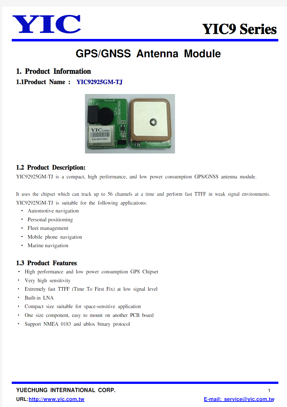
1.1Product Name :YIC92925GM-TJ
1.2 Product Description:
YIC92925GM-TJ is a compact, high performance, and low power consumption GPS/GNSS antenna module.
It uses the chipset which can track up to 56 channels at a time and perform fast TTFF in weak signal environments. YIC92925GM-TJ is suitable for the following applications:
? Automotive navigation
? Personal positioning
? Fleet management
?Mobile phone navigation
? Marine navigation
1.3 Product Features:
?High performance and low power consumption GPS Chipset
? Very high sensitivity
? Extremely fast TTFF (Time To First Fix) at low signal level
? Built-in LNA
? Compact size suitable for space-sensitive application
? One size component, easy to mount on another PCB board
? Support NMEA 0183 and ublox binary protocol
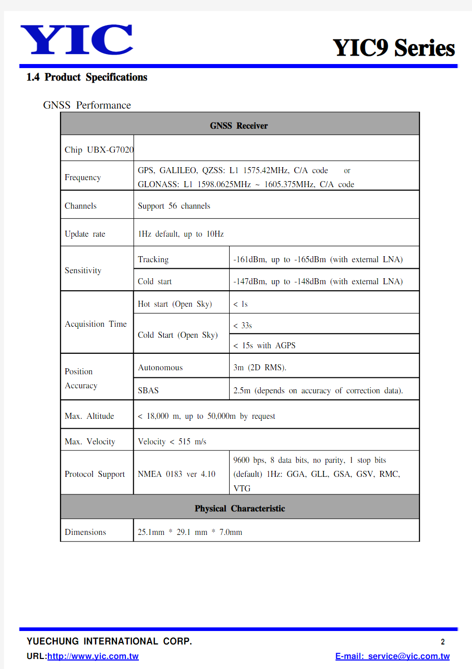
1.4 Product Specifications
GNSS Performance
GNSS Receiver Chip UBX-G7020
Frequency GPS, GALILEO, QZSS: L1 1575.42MHz, C/A code or GLONASS: L1 1598.0625MHz ~ 1605.375MHz, C/A code
Channels Support 56 channels
Update rate 1Hz default, up to 10Hz
Sensitivity
Tracking -161dBm, up to -165dBm (with external LNA)
Cold start -147dBm, up to -148dBm (with external LNA) Acquisition Time
Hot start (Open Sky) < 1s
Cold Start (Open Sky)
< 33s
< 15s with AGPS
Position Accuracy Autonomous 3m (2D RMS).
SBAS 2.5m (depends on accuracy of correction data).
Max. Altitude < 18,000 m, up to 50,000m by request Max. Velocity Velocity < 515 m/s
Protocol Support NMEA 0183 ver 4.10 9600 bps, 8 data bits, no parity, 1 stop bits (default) 1Hz: GGA, GLL, GSA, GSV, RMC, VTG
Physical Characteristic Dimensions 25.1mm * 29.1 mm * 7.0mm
1.5 DC Electrical characteristics
Parameter Symbol Conditions Min.Typ. Max. Units Input Voltage VCC 3.0 3.3 4.3 V
Input Backup Battery Voltage V_BCKP 2.0
4.3
V
Supply Current Iss VCC = 3.3V,
w/o active antenna,
Peak
Acquisition
Tracking
Standby
24
16(2)
365
150(1)mA
mA
mA
uA
Backup Battery Current Ibat VCC = 0V 7 uA
High Level Input Voltage VIH 2.0
3.6 V
Low Level Input
Voltage
VIL -0.3 0.8 V High Level Input
Current
IIH no pull-up or down -1 1 uA Low Level Input
Current
IIL no pull-up or down -1 1 uA High Level Output
Voltage
VOH 2.4 3.3 V Low Level Output
Voltage
VOL 0.4 V High Level Output
Current
IOH 2 mA Low Level Output
Current
IOL 2 mA Note 1: This happens when downloading AGPS data to Module.
Note 2: Measured when position fix (1Hz) is available, input voltage is 3.3V and the function of self-generated ephemeris prediction is inactive.
Temperature characteristics
Parameter Symbol Min. Typ. Max. Units Operating Temperature Topr -40 25 85 ℃
Storage Temperature Tstg -40 25 85 ℃
2. Module Pin Assignment & Dimensions
Module Pin Assignment
Dimensions
Pin NO. Pin Name
I/O Remark
1. VCC
+5V / +3.3V 2.
TXD O
3. GND G Ground.
4.
RXD
I
3. Application guideline
Layout Rules
Do not routing the other signal or power trace under the engine board .
Design Notes
VBAT
Plug-in RTC Battery Input: 2.0 ~ 3.6V (DC)
TXD
This is the main transmits channel for outputting navigation and measurement data to user’s navigation software or user written software.
RXD
This is the main channel for receiving software commands from u-blox software or from your proprietary software.
VCC
Module Power Supply, Module Power Supply.
GND
Ground pin for the baseband circuit.
4. NMEA 0183 Protocol
The NMEA protocol is an ASCII-based protocol, Records start with a $ and with carriage return/line feed. GPS specific messages all start with $GPxxx where xxx is a three-letter identifier of the message data that follows. NMEA messages have a checksum, which allows detection of corrupted data transfers.
YIC92925GM-TJ modules support the following NMEA-0183 messages: GGA, GLL,GSA, GSV, RMC and VTG. Table 1: NMEA-0183 Output Messages
NMEA Record DESCRIPTION
GGA Global positioning system fixed data
GLL Geographic position—latitude/longitude
GSA GNSS DOP and active satellites
GSV GNSS satellites in view
RMC Recommended minimum specific GNSS data
VTG Course over ground and ground speed
GGA-Global Positioning System Fixed Data
Table 2 contains the values of the following example:
$GPGGA,183015.000,2503.7123,N,12138.7446,E,2,16,0.68,123.2,M,15.3,M,0000,0000*66 Table 2: GGA Data Format
Name Example Units Description Message ID $GPGGA GGA protocol header
UTC Position183015.000hhmmss.sss
Latitude2503.7123ddmm.mmmm
N/S indicator N N=north or S=south
Longitude 12138.7446 dddmm.mmmm
E/W Indicator E E=east orW=west
2 See Table 2-1
Position Fix Indicator
Satellites Used 16 Range 0 to 33
HDOP 0.68 Horizontal Dilution of Precision MSL Altitude 123.2 meters
Units M meters
Geoids Separation 15.3 meters
Units M meters
Age of Diff. Corr. 0000 second Null fields when DGPS is not Used
Diff. Ref. Station ID0000
Checksum *66
Table 2-1: Position Fix Indicators
Value Description
0 Fix not available or invalid
1GPS SPS Mode, fix valid
2Differential GPS, SPS Mode, fix valid
3-5Not supported
Dead Reckoning Mode, fix valid
6
GLL-Geographic Position – Latitude/Longitude
Table 3 contains the values of the following example:
$GPGLL , 3723.24755, N,12158.34161,W,161229.487, A,D*2C.
Table 3: GLL Data Format
Name Example Units Description Message ID $GPGLL GLL protocol header
Latitude3723.24755ddmm.mmmmm
N/S Indicator N N=north or S=south
Longitude 12158.34161 dddmm.mmmmm
E/W Indicator W E=east orW=west
UTC Position
161229.487 hhmmss.sss
Status A A=data valid or V=data not valid
Mode D A=autonomous, D=DGPS, E=DR,
N=Data not valid, R=Coarse Position, S=Simulator
Checksum *2C
GSA-GNSS DOP and Active Satellites
Table 4 contains the values of the following example:
$GNGSA,A,3,18,193,21,09,12,22,27,15,25,14,,,1.44,0.68,1.27*2F
$GNGSA,A,3,76,72,77,75,66,65,,,,,,,1.44,0.68,1.27*12
Table 4: GSA Data Format
Name Example Units Description Message ID $GNGSA GSA protocol header
Mode 1A See Table 4-2
Mode 23See Table 4-1
ID of satellite used 18 Sv on Channel 1
ID of satellite used 193 Sv on Channel 2
… …
…
ID of satellite used
Sv on Channel 12
PDOP 1.44 Position Dilution of Precision
HDOP 0.68 Horizontal Dilution of Precision
VDOP 1.27 Vertical Dilution of Precision
Checksum *2F
Table 4-1: Mode 1
Value Description
1Fix not available
22D
33D
Table 4-2: Mode 2
Value Description
M Manual-forced to operate in 2D or 3D mode
A Automatic-allowed to automatically switch 2D/3D
GSV-GNSS Satellites in View
Table 5 contains the values of the following example:
$GPGSV,3,1,11,18,67,344,48,09,55,031,50,42,54,142,40,193,47,174,45*4D
$GPGSV,3,2,11,21,44,219,46,27,39,035,48,12,34,131,44,15,30,057,46*76
$GPGSV,3,3,11,22,27,319,47,14,22,285,42,25,19,171,40*44
$GLGSV,2,1,07,76,71,201,44,65,57,041,40,75,48,028,39,72,27,108,39*68
$GLGSV,2,2,07,66,25,333,43,77,17,207,37,81,02,280,29*5C
Table 5: GSV Data Format
Name Example Units Description
Message ID $GPGSV GSV protocol header (GPGSV and GLGSV) Number of Message(1)3Range 1 to 6
Message Number(1)1Range 1 to 6
Satellites in View 11
Satellite ID 18 Channel 1(Range 1 to 196)
degrees Channel 1(Range 0 to 90)
Elevation 67
344 degrees Channel 1( Range 0 to 359)
Azinmuth
SNR(C/NO) 48 dBHz Channel 1( Range 0 to 99,null when not tracking)… …
Satellite ID 09 Channel 4(Range 1 to 196)
degrees Channel 4(Range 0 to 90)
Elevation 55
degrees Channel 4( Range 0 to 359)
Azimuth 031
SNR(C/NO) 50 dBHz Channel 4( Range 0 to 99, null when not tracking)
Checksum *4D
Note1: Depending on the number of satellites tracked multiple messages of GSV data may be required
RMC-Recommended Minimum Specific GNSS Data
Table 6 contains the values of the following example:
$GNRMC,183015.000,A,2503.7123,N,12138.7446,E,0.01,34.92,270812,,,D*43
Table 6: RMC Data Format
Name Example Units Description
Message ID $GNRMC RMC protocol header (GNRMC or GPRMC)
UTS Position183015.000hhmmss.sss
Status A A=data valid or V=data not valid
Latitude 2503.7123 ddmm.mmmm
N/S Indicator N N=north or S=south
dddmm.mmmm
Longitude 12138.7446
E E=east orW=west
E/W Indicator
Speed Over Ground 0.01 Knots True
Course Over Ground 34.92 Degrees
Date 270812 ddmmyy
Magnetic variation Degrees
Variation sense E=east or W=west (Not shown)
Mode D
A=autonomous, D=DGPS, E=DR, N=Data not
valid, R=Coarse Position, S=Simulator Checksum *43
VTG-Course Over Ground and Ground Speed
Table 7 contains the values of the following example:
$GPVTG,34.92,T,,M,0.01,N,0.02,K,D*07
Table 7: VTG Data Format
Name Example Units Description
Message ID $GPVTG VTG protocol header
Course34.92Degrees Measured heading
Reference T True
Course Degrees Measured heading
Reference M Magnetic
Measured horizontal speed
Speed 0.01 Knots
N Knots
Units
Speed 0.02 Km/hr Measured horizontal speed
Units K Kilometer per hour
Mode D
A=autonomous, D=DGPS, E=DR, N=Data not
valid, R=Coarse Position, S=Simulator Checksum *07