? Copyright 2011–2012 Xilinx, Inc. Xilinx, the Xilinx logo, Artix, ISE, Kintex, Spartan, Virtex, Zynq, and other designated brands included herein are trademarks of Xilinx in the United States and other countries. PCI, PCI Express, PCIe, and PCI-X are trademarks of PCI-SIG. All other trademarks are the property of their respective owners.
Introduction
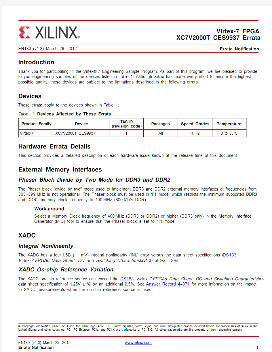
Thank you for participating in the Virtex?-7 Engineering Sample Program. As part of this program, we are pleased to provide to you engineering samples of the devices listed in Table 1. Although Xilinx has made every effort to ensure the highest possible quality, these devices are subject to the limitations described in the following errata.
Devices
These errata apply to the devices shown in Table 1.Hardware Errata Details
This section provides a detailed description of each hardware issue known at the release time of this document.
External Memory Interfaces
Phaser Block Divide by Two Mode for DDR3 and DDR2
The Phaser block "divide by two" mode used to implement DDR3 and DDR2 external memory interfaces at frequencies from 303–399MHz is not operational. The Phaser block must be used in 1:1 mode, which restricts the minimum supported DDR3 and DDR2 memory clock frequency to 400MHz (800Mb/s DDR).
Work-around
Select a Memory Clock frequency of 400MHz (DDR3 or DDR2) or higher (DDR3 only) in the Memory Interface Generator (MIG) tool to ensure that the Phaser block is set to 1:1 mode.
XADC
Integral Nonlinearity
The XADC has a four LSB (~1 mV) integral nonlinearity (INL) error versus the data sheet specifications (DS183, Virtex-7FPGAs Data Sheet: DC and Switching Characteristics, v1.3) of two LSBs.
XADC On-chip Reference Variation
The XADC on-chip reference source can exceed the DS183, Virtex-7FPGAs Data Sheet: DC and Switching Characteristics data sheet specification of 1.25V ±1% by an additional 0.5%. See Answer Record 44971 for more information on the impact to XADC measurements when the on-chip reference source is used.
Virtex-7 FPGA
XC7V2000T CES9937 Errata
EN180 (v1.3) March 29, 2012
Errata Notification
Table 1:Devices Affected by These Errata
Product Family Device
JTAG ID (revision code)
Packages
Speed Grades
Temperature Virtex-7
XC7V2000T CES9937
1
All
-1, -2
0 to 85°C
GTX Transceivers
Out-of-Band Signaling
The GTX transceiver circuitry for out-of-band (OOB) signaling is always enabled.
GTX Line Rate
The GTX transceiver operation is limited to a maximum of 6.6 Gb/s.
QPLL Frequency Range
The supported QPLL frequency range is 5.93–6.6 GHz.
TXOUTCLK and RXOUTCLK Ports
The GTX transceiver TXOUTCLK and RXOUTCLK ports can exhibit loss of edges or excessive jitter when used simultaneously within a GTX channel and with other channels in a transceiver Quad.
The following rules must be followed for proper operation of TXOUTCLK and RXOUTCLK:
?Use either TXOUTCLK or RXOUTCLK within any GTX channel, not both.
?Use either TXOUTCLK of GTX0 or RXOUTCLK of GTX1, not both.
?Use the reference clock directly from IBUFDS_GTXE2 to drive the fabric logic and GTX user clocks when necessary ([TX/RX]USRCLK, [TX/RX]USRCLK2).
Set RXOUTCLKSEL = 3'b000 when RXOUTCLK is not used. Set TXOUTCLKSEL = 3'b000 when TXOUTCLK is not used.
See Answer Record 43244for more information.
QPLL Use Mode
The QPLL can lose lock if reset at one temperature extreme and operated at the other.
Work-around
See Answer Record 43244for the user design work-around.
Receiver Link Margin
The receiver can have a reduction in jitter tolerance when used in full-rate mode (RXOUT_DIV == 1).
Work-around
See Answer Record 43244 for attribute updates and equalization selection.
CPLL Jitter
The GTX CPLL when operated at 3.1 GHz, or above, can exhibit higher jitter when MGT AVTT is higher than nominal. Transmit Electrical Idle
The transmitter common mode voltage is higher than expected when TX electrical idle is enabled. The electrical idle detection in the receiver is not impacted when links are AC coupled.
Receiver Detection for PCIe
The Receiver Detection feature used for PCIe? applications is not supported.
Work-around
Set the following attributes to force the transmitter to always detect a receiver:
-TX_RXDETECT_REF = 3'b000
-RX_CM_SEL = 2'b11
-(PMA_RSV2[4], RX_CM_TRIM[2:0]) = 4’b1010
PCIe ASPM Support
ASPM L0s is not supported for Gen 2 (5 Gb/s) line rate.
Work-around
Set the following attributes on the Integrated Block for PCI Express to disable ASPM L0s:
-LINK_CAP_ASPM_OPTIONALITY = TRUE
-LINK_CAP_ASPM_SUPPORT= 0
See Answer Record 43243 for additional details.
IEEE Std 1149.6 for GTX Transceivers
In the devices listed in Table1, IEEE Std 1149.6 (ACJTAG) boundary-scan test commands EXTEST_PULSE and EXTEST_TRAIN are not supported.
IEEE Std 1149.1 JTAG
IEEE Std 1149.1 (JT AG) IDCODE[31:0] is 136BF093 (hex).
SelectIO Resources
Internal Weak Pull-Ups/Pull-Downs for High-Range I/O Bank0
The internal weak pull-ups/pull-downs for the high-range (HR) I/O configuration bank 0 will not achieve valid logic-1 and logic-0 states for 1.8V and lower V CCO_0. External resistors should be used for V CCO_0 of 1.8V and lower.
Power
Static Current
The devices listed in Table1 can exhibit up to 50% higher static current on all supplies, except MGTAVTT, compared to the static current reported in XPE 13.3. The MGTAVTT supply can consume up to a total of 20mA per powered transceiver Quad. Also, up to an additional 95 mA can be consumed by the MGTAVCC supply for each powered and uninstantiated transceiver Quad.
Power-On/Off Requirement
For V CCO_0 voltages of 3.3V in the high-range (HR) I/O configuration bank 0, the following requirements must be followed:?When V CCINT is less than 0.7V, V CCO_0 must not exceed 2.625V for longer than 800ms with T j = 85°C for each power-on/off cycle to maintain device reliability levels.
?This time can be allocated in any percentage between the power-on and power-off ramps.
?This time is based on 240,000 power cycles with nominal V CCO_0 of 3.3V or 36,500 power cycles with a worst case V CCO_0 of 3.465V.
Packaging
Package Coplanarity
The package coplanarity (mechanical drawing symbol aaa) tolerance can be up to 0.30 mm (12 mils). Follow the guidelines in XAPP426: Implementing Xilinx Flip-Chip BGA Packages to ensure an optimal solder reflow profile.
Package Assembly
Bake units for 4hours at 125°C before assembly. Within 30 minutes of taking the units from the bake oven, assemble them on the final system board. Failure to follow this baking procedure can result in device damage during assembly. Configuration
Single Event Upset (SEU) Detection and Correction
SEU detection or correction (POST_CRC=ENABLE) is not supported.
Design Software Requirements
The devices listed in Table1, unless otherwise specified, require the following Xilinx Design Tools:
?Please coordinate with your Xilinx Field Application Engineer to assure you have access to the correct version of advanced tools.
Operational Guidelines
Designs targeting DDR3 data rates above 800 Mb/s must include an external V REF. For further details, refer to
Answer Record 42036.
Traceability
The XC7V2000T devices listed in Table1 are marked as shown in Figure1.
Figure 1:Example Device Top Mark
Additional Questions or Clarifications
For additional questions regarding these errata, contact Xilinx Technical Support:
https://www.doczj.com/doc/dd4017592.html,/support/clearexpress/websupport.htm or your Xilinx Sales Representative:
https://www.doczj.com/doc/dd4017592.html,/company/contact/index.htm.
Revision History
The following table shows the revision history for this document:
Date Version Description of Revisions
12/01/11 1.0Initial Xilinx release.
01/24/12 1.1Added Dual Rank for DDR3 and DDR2. Updated Phaser Block Divide by Two Mode for DDR3 and
DDR2 and XADC On-chip Reference Variation. Added Out-of-Band Signaling.
02/28/12 1.2Removed Dual Rank for DDR3 and DDR2; silicon support for dual rank reinstated.
03/29/12 1.3Updated Package Coplanarity and Package Assembly.
Notice of Disclaimer
The information disclosed to you hereunder (the “Materials”) is provided solely for the selection and use of Xilinx products. T o the maximum extent permitted by applicable law: (1) Materials are made available “AS IS” and with all faults, Xilinx hereby DISCLAIMS ALL WARRANTIES AND CONDITIONS, EXPRESS, IMPLIED, OR STA TUTORY, INCLUDING BUT NOT LIMITED TO WARRANTIES OF MERCHANTABILITY, NON-INFRINGEMENT, OR FITNESS FOR ANY P ARTICULAR PURPOSE; and (2) Xilinx shall not be liable (whether in contract or tort, including negligence, or under any other theory of liability) for any loss or damage of any kind or nature related to, arising under, or in connection with, the Materials (including your use of the Materials), including for any direct, indirect, special, incidental, or consequential loss or damage (including loss of data, profits, goodwill, or any type of loss or damage suffered as a result of any action brought by a third party) even if such damage or loss was reasonably foreseeable or Xilinx had been advised of the possibility of the same. Xilinx assumes no obligation to correct any errors contained in the Materials or to notify you of updates to the Materials or to product specifications. Y ou may not reproduce, modify, distribute, or publicly display the Materials without prior written consent. Certain products are subject to the terms and conditions of the Limited Warranties which can be viewed at https://www.doczj.com/doc/dd4017592.html,/warranty.htm; IP cores may be subject to warranty and support terms contained in a license issued to you by Xilinx. Xilinx products are not designed or intended to be fail-safe or for use in any application requiring fail-safe performance; you assume sole risk and liability for use of Xilinx products in Critical Applications: https://www.doczj.com/doc/dd4017592.html,/warranty.htm#critapps.
Engineering Sample Disclaimer
ENGINEERING SAMPLE (ES) DEVICES ARE MADE AVAILABLE SOLEL Y FOR PURPOSES OF RESEARCH, DEVELOPMENT AND PROTOTYPING. ALL ES DEVICES ARE SOLD “AS-IS” WITH NO WARRANTY OF ANY KIND, EITHER EXPRESS OR IMPLIED. XILINX DOES NOT WARRANT THA T ES DEVICES ARE FULL Y VERIFIED, TESTED, OR WILL OPERA TE IN ACCORDANCE WITH DA T A SHEET SPECIFICA TIONS. XILINX DISCLAIMS ANY OBLIGA TIONS FOR TECHNICAL SUPPORT AND BUG FIXES. XILINX SHALL NOT BE LIABLE FOR ANY DAMAGES, INCLUDING WITHOUT LIMITA TION DIRECT, INDIRECT, INCIDENTAL, SPECIAL, RELIANCE, OR CONSEQUENTIAL DAMAGES ARISING FROM OR IN CONNECTION WITH THE USE OF ES DEVICES IN ANY MANNER WHA TSOEVER, EVEN IF XILINX HAS BEEN ADVISED OF THE POSSIBILITY THEREOF. XILINX MAKES NO REPRESENT A TION THA T ES DEVICES PROVIDE ANY P ARTICULAR FUNCTIONALITY, OR THA T ES DEVICES WILL MEET THE REQUIREMENTS OF A P ARTICULAR USER APPLICA TION. XILINX DOES NOT WARRANT THA T ES DEVICES ARE ERROR-FREE, NOR DOES XILINX MAKE ANY OTHER REPRESENT A TIONS OR WARRANTIES, WHETHER EXPRESS OR IMPLIED, ST A TUTORY OR OTHERWISE, INCLUDING, WITHOUT LIMIT A TION, IMPLIED WARRANTIES OF MERCHANTABILITY, FITNESS FOR A P ARTICULAR PURPOSE, OR NON-INFRINGEMENT. THE FOREGOING STA TES THE ENTIRE LIABILITY OF XILINX WITH RESPECT TO ES DEVICES.