【机械类文献翻译】对螺杆压缩机的三维分析开发
- 格式:doc
- 大小:3.27 MB
- 文档页数:16
毕业设计论文单螺杆空气压缩机的设计摘要空气压缩机具有结构简单、工作可靠和操作方便等一系列独特的优点,因此在空气动力学、制冷空调及各种工艺流程中获得了广泛的应用。
可编程控制器(PLC)将传统的继电器控制技术、计算机控制技术和通信技术融为一体,专为工业控制而设计。
本文介绍了空气压缩机PLC控制系统组成、保护功能、控制原理、系统通信、系统信号的采集,以及控制系统软件的设计思想。
单螺杆压缩机亦称蜗杆压缩机,采用高效带轮传动,带动主机转动进行空气压缩,通过喷油对主机内的压缩空气进行冷却,主机排出的空气和油混合气体经过粗、精两道分离,将压缩空气中的油分离出来,最后得到洁净的压缩空气。
冷却器用于冷却压缩空气和油。
因其在结构、力学及可靠性等方面的独特优势,广泛应用于船舶、机车、能源、国防、石油、化工、机械、食品、轻纺等行业,具有优良的可靠性能,振动小、噪声低、操作方便、易损件少、运行效率高是其最大的优点。
关键词: 可编程控制器(PLC)单螺杆空气压缩机控制Air compressor has a simple structure, reliable and easy to operate and a series of unique advantages, so aerodynamics, refrigeration and air conditioning and a variety of process to obtain a wide range of applications. Programmable Logic Controller (PLC) to the traditional relay control technology, computer control technology and communication technology integration, specifically designed for industrial control. This article describes the composition of the air compressor PLC control system, protection, control theory, system communication, system signal acquisition and control system software design. Single-screw compressors also known as worm compressor, using high pulley drive, drive rotation to host the air compressed within the host by injection of compressed air for cooling, host the exhaust air and oil mixture through the coarse, fine 2 separation, the compressed air oil separation, and finally get clean air. Cooler for cooling compressed air and oil. Because of their structural, mechanical and reliability aspects of the unique advantages of widely used in ships, locomotives, energy, defense, petroleum, chemicals, machinery, food, textile and other industries, with high reliability, little vibration, low noise convenient operation, the vulnerability of small, high operating efficiency of its greatest strengths.Key words: single-screw air compressors, programmable logic controllers, control第1章绪论 (1)1.1单螺杆压缩机的历史及现状 (1)1.2单螺杆空气压缩机在国内外概况与优缺点 (1)1.2.1 单螺杆空气压缩机在国内外的概况 (1)1.2.2 单螺杆空气压缩机的优点与缺点 (2)1.2.3 单螺杆空气压缩机的开发关键技术 (3)1.3 单螺杆空气压缩机的结构设计 (4)1.4 PLC的发展史 (6)第2章硬件设计 (11)2.1系统工作原理 (10)2.1.1系统流程及零件功能简介 (10)2.2 单螺杆空气压缩机的PLC控制系统的设计 (13)2.2.1 PLC的结构及基本配置 (13)2.2.2 可编程控制器的特点 (15)2.2.3可编程控制器的发展 (17)2.2.4可编程控制器的工作原理 (18)2.2.5控制系统PLC设计原则 (19)2.2.6 PLC的选型设计 (19)2.3 FX3U-64MT的意思及其编程元件 (21)2.4 BCD的工作原理 (26)第3章软件设计 (30)3.1软件流程图的软件设计 (30)3.2 软件流程图 (30)3.3 FX3U-64MT系列PLC编程语言及系统控制原理 (31)3.4 FX3U系列的基本逻辑指令 (36)3.5功能图编程语言 (39)3.6设计梯形图 (40)第四章维修与保养. . . . . . . . . . . . . . . . . . . . 464.1 空压机的压力调节器整定. . . . . . . . . . . . . . . . . . 464.2 空气滤清器. . . . . . . . . . . . . . . . . . . . . .. (46)4.3 冷却器及安全阀. . . . . . . . . . . . . . . . . . . . . . . 46.4.3.1 冷却器. . . . . . . . . . . . . . . . . . . . . . . 464.3.2 安全阀. . . . . . . . . . . . . . . . . . . . . . . 464.4 数显温度计实验及电机过载继电器. . . . . . . . . . . . . . 474.4.1 数显温度计实验. . . . . . . . . . . . . . . . . . . .474.4.2 电机过载继电器. . . . . . . . . . . . . . . . . . . .47 结论 (47)参考文献 (48)致谢 (49)附录. . . . . . . . . . . . .. . . . . . .. . . .. . . . . .50第1章绪论1.1单螺杆压缩机的历史及现状1960年法国辛麦恩(B.Zimmern)提出了单螺杆压缩机的构想,并获得专利权,1962年试制出第一台样机,70年代初期由法国标致汽车公司正式生产投放市场。
基于计算流体力学的双螺杆泵的数值模拟由于其在单相或多相操作可靠性和优良的性能,双螺杆泵是广泛应用于石油化工、航运、能源和食品工业正排量机械。
图1中给出了一个双螺杆泵的典型布置图,显示转子同步定时齿轮和封闭的外壳。
越来越高的要求对于高性能螺杆泵设计改进需要越来越高的要求。
最近的在制造技术的发展,可以准确地生产新颖的设计。
但在螺杆泵设计方面的改进,充分了解泵内的过程是必需的。
到目前为止,大多数模型的性能分析的基础是热力室建模。
双螺杆泵的结构和成分许多以前的研究报告了双螺杆泵的工作过程建模和实验研究工作的报告。
文学资源的数量是大的,因此,只有最相关的将在下面列出李[ 1 ]介绍了各种螺杆泵的结构、齿形的产生及性能计算。
冯c.et.al [ 2 ]建立模型后的流量和压力的产生多相双螺杆泵内和模拟的热力学性能和不同气体体积分数的泵所输送的行为,唐张[ 3 ]模拟基于CFD的静态网格流场动力学提出了泄漏模型的双螺杆泵,他们还优化了齿廓。
泾渭[ 4 ]讨论了双螺杆齿形设计基于CFD的模拟机和静态网格流场。
D. Mewes [ 5 ]提出了根据质量和能量的多相泵性能计算模型在泵室的保护,并通过实验验证。
阿沛帕蒂尔[ 6 ]和埃文陈[ 7 ]研究了不同工作条件下的稳态和暂态特性。
他们讨论了密封液粘度和气体空隙率的影响关于双螺杆泵性能的研究。
K.雷比格尔[ 8 ]提出了一个模型螺杆泵,并对泵性能进行了数值计算和实验分析在非常高的气体体积分数(99% - 90%),他还进行了实验,以可视化泄漏流动的径向间隙[ 9 ]。
文献资源的引用提供了一个很好的理解的工作过程中,但指出,改善是可能的,特别是多相泵的新应用。
然而,大多数的电流的方法是基于热力学室忽视动能的数学模型,简化了主、漏流分析(10)(11).一些人指的是稳态计算流体动力学假设移动流域静态网格,近似压力梯度和泄漏速度场可以获采用静态网格得,然而,这样的结果不考虑的速度场的主要流动和忽视的工作过程中的螺杆泵的瞬态特性.由于采用静态网格的计算流体力学模拟的限制,一些重要的参数不能得到,如质量流量,转子转矩和压力波动, 所以,一个多相泵压力场在静态网格结果明显会有所不同,因此功率计算不准确;此外,压力流量损失无法计算.因此,如功率损耗,间隙变化的影响,包括空化和多相流的任何动态行为的现象不能使用这样的静态网格分析.螺杆泵工作域在动转子与固定套管之间。
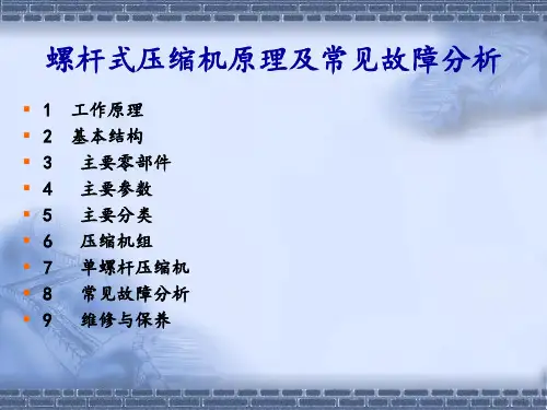
题目: 螺杆式空气压缩机的结构设计学院专业(层次)机械工程及自动化年级2012级班级学生姓名学号指导教师目录目录 (I)摘要 (III)[ABSTRACT] (IV)绪论 (V)1.螺杆压缩机简介 (V)2.螺杆压缩机的特点和应用前景 (VII)2。
1螺杆压缩机的特点 (VII)2。
2螺杆压缩机的应用前景 (VIII)3.国内外螺杆压缩机的研究进展 ..................................................................................................... I X4.本文的主要研究内容 (X)第一章系统原理图的设计 (1)1。
1螺杆空气压缩机主要组成及原理 (1)1.2风冷与水冷的基本区别 (1)1.3系统原理图的设计 (2)第二章螺杆压缩机主机的结构原理及选择 (3)2.1基本结构 (3)2。
2工作原理 (3)2.3电机的选择 (6)第三章螺杆压缩机主要零部件的工作原理及选择 (7)3.1进气阀、安全阀、保压阀、温控阀的工作原理及选择 (7)3。
1。
1进气阀 (7)3。
1.2安全阀 (8)3.1.3保压阀 (9)3.1.4温控阀 (10)3。
2空滤、油滤、油分芯的作用 (10)3.3油气分离器的设计 (13)3。
4冷却器及风扇的选型设计 (15)3。
4.1冷却器的选择 (15)3.4.2风扇的选择 (17)3.5连接配管的选型设计 (18)第四章螺杆压缩机的结构布局设计 (20)4.1整体结构设计及说明 (20)4.1.1零部件布局说明 (20)4.1。
2管路系统设计说明 (22)4。
2机组系统运转说明 (23)4.3噪音防护处理 (25)4。
4外部钣金设计 (28)第五章螺杆压缩机维护及保养 (30)5.1螺杆空气压缩机的日常维护 (30)5.2螺杆空气压缩机的常见故障分析及处理 (32)总结 (35)致谢 (37)参考文献 (38)螺杆式空气压缩机的结构设计摘要空压机是各种工厂、筑路、矿山及建筑行业的必备设备,主要用来提供源源不断的具有一定压力的压缩空气.空压机有很多种类,如螺杆式空压机、活塞式空压机、离心式空压机、涡旋式空压机等等。
毕业设计三维设计在车辆系统零部件的应用摘要三维技术几乎被所有汽车公司所采用,可以说三维技术(包括计算机辅助制造、计算机辅助工程分析)的应用水平,已经成为评价一个国家汽车工业水平的重要指标。
在我国,汽车企业一直都作为国家和地方的利税大户,同时也是三维技术应用的先锋。
三维技术在企业中的成功应用,不仅带来了企业技术上的创新,同时带动了企业经营、管理旧模式的变革。
因此,它对我国传统产业的改造、新技术的兴起,以及汽车工业提高国际竞争力等方面,起到了巨大的推动作用。
随着计算机技术的飞速发展,CAD已经广泛用于各个社会生产领域,特别是对于生产复杂产品如飞机、汽车、家电等制造业尤为重要。
汽车是一件复杂的产品,其开发流程涉及到极大的工作量,借助于先进的三维技术,能降低开发人员的工作量并提高产品质量。
本文将根据模具设计、车身设计、底盘布置设计、汽车轻量化等方面来阐述三维技术的应用状况及其发展前景。
冲压艺术、结果设计和制造技术是汽车模具生产技术的集中体现,这些技术的进步主要取决于CAD/CAM/CAE技术的提高。
在汽车模具制造行业,计算机应用技术和数控加工技术正越来越显示出其核心技术的作用。
关键词:三维技术,汽车零部件,前景广阔目录摘要 (2)1 三维技术对汽车企业的重要性 (4)2 CAD的概述 (4)2.1CAD的诞生于发展 (4)2.2CAD的应用 (6)2.2.1 CAD在各重要领域广泛应用 (6)2.2.2 CAD在汽车制造上的优缺点 (8)2.3CAD的发展趋势 (9)3 三维技术在汽车工程领域的应用状况 (10)3.1汽车模具三维技术 (10)3.2汽车车身覆盖件三维技术 (11)3.3汽车底盘三维技术 (12)3.4三维技术在汽车轻量化中的应用 (12)3.5近年来汽车工业CAD/CAM/CAE系统选型趋向 (13)4 三维技术在汽车制造方面前景广阔 (13)5 总结 (17)致谢 (18)参考文献: (19)1 三维技术对汽车企业的重要性汽车行业是三维技术最先应用的领域之一,国外一些著名的汽车公司很早就自行开发C AD软件。

分类号:____________ 密 级:______________ TH164 锥双螺杆的三维建模与啮合间隙研究公开 UDC:____________ 单位代码: 10142硕士学位论文 论文题目:锥双螺杆的三维建模与啮合间隙研究韩例岑学 号:_________________________ 2007020 作 者:_________________________ 韩例岑 学 科 名 称:_________________________ 机械制造及其自动化 沈阳工业大学2009年 12月 30日沈阳工业大学硕士学位论文论文题目:锥双螺杆的三维建模与啮合间隙研究韩例岑作者:_________________________王可教授指导教师:单位:沈阳工业大学孙兴伟副教授协助指导教师:单位:沈阳工业大学单位:论文提交日期:2009年12月30日学位授予单位:沈阳工业大学A Dissertation Submitted to Shenyang University of Technology forthe Master DegreeRESEARCH ON 3D MODELING AND MESHING CLEARANCE OF CONICAL TWIN-SCREWAuthor: Han LicenMajor:Mechanical Manufacturing and AutomationSupervisor:Professor Wang KeSchool of Mechanical EngineeringShenyang University of TechnologyShenyang, P.R.ChinaDecember 30, 2007独 创 性 说 明本人郑重声明:所呈交的论文是我个人在导师指导下进行的研究工作及取得的研究成果。
尽我所知,除了文中特别加以标注和致谢的地方外,论文中不包含其他人已经发表或撰写的研究成果,也不包含为获得沈阳工业大学或其他教育机构的学位或证书所使用过的材料。

文献翻译英文原文:NOVEL METHOD OF REALIZING THE OPTIMAL TRANSMISSION OF THE CRANK-AND-ROCKER MECHANISM DESIGN Abstract: A novel method of realizing the optimal transmission of the crank-and-rocker mechanism is presented. The optimal combination design is made by finding the related optimal transmission parameters. The diagram of the optimal transmission is drawn. In the diagram, the relation among minimum transmission angle, the coefficient of travel speed variation, the oscillating angle of the rocker and the length of the bars is shown, concisely, conveniently and directly. The method possesses the main characteristic. That it is to achieve the optimal transmission parameters under the transmission angle by directly choosing in the diagram, according to the given requirements. The characteristics of the mechanical transmission can be improved to gain the optimal transmission effect by the method. Especially, the method is simple and convenient in practical use.Keywords:Crank-and-rocker mechanism, Optimal transmission angle, Coefficient of travel speed variationINTRODUCTIONBy conventional method of the crank-and-rocker design, it is very difficult to realize the optimal combination between the various parameters for optimal transmission. The figure-table design method introduced in this paper can help achieve this goal. With given conditions, we can, by only consulting the designing figures and tables, get the relations between every parameter and another of the designed crank-and-rocker mechanism. Thus the optimal transmission can be realized.The concerned designing theory and method, as well as the real cases of its application will be introduced later respectively.1ESTABLISHMENT OF DIAGRAM FOR OPTIMAL TRANSMISSION DESIGNIt is always one of the most important indexes that designers pursue to improve the efficiency and property of the transmission. The crank-and-rocker mechanism is widely used in the mechanical transmission. How to improve work ability and reduce unnecessary power losses is directly related to the coefficient of travel speed variation, the oscillating angle of the rocker and the ratio of the crank and rocker. The reasonable combination of these parameters takes an important effect on the efficiency and property of the mechanism, which mainly indicates in the evaluation of the minimum transmission angle.The aim realizing the optimal transmission of the mechanism is how to find themaximum of the minimum transmission angle. The design parameters are reasonably combined by the method of lessening constraints gradually and optimizing separately. Consequently, the complete constraint field realizing the optimal transmission is established.The following steps are taken in the usual design method. Firstly, the initial values of the length of rocker 3l and the oscillating angle of rocker ϕ are given. Then the value of the coefficient of travel speed variation K is chosen in the permitted range. Meanwhile, the coordinate of the fixed hinge of crank A possibly realized is calculated corresponding to value K .1.1 Length of bars of crank and rocker mechanismAs shown in Fig.1, left arc G C 2 is the permitted field of point A . Thecoordinates of point A are chosen by small step from point 2C to point G .The coordinates of point A are 02h y y c A -= (1)22A A y R x -= (2)where 0h , the step, is increased by small increment within range(0,H ). If the smaller the chosen step is, the higher the computational precision will be. R is the radius of the design circle. d is the distance from 2C to G .2cos )2cos(22cos 33ϕθϕϕ⎥⎦⎤⎢⎣⎡--+=l R l d (3) Calculating the length of arc 1AC and 2AC , the length of the bars of themechanism corresponding to point A is obtained [1,2].1.2 Minimum transmission angle min γMinimum transmission angle min γ(see Fig.2) is determined by the equations [3]322142322min 2)(cos l l l l l l --+=γ (4) 322142322max 2)(cos l l l l l l +-+=γ (5) max min180γγ-︒=' (6) where 1l ——Length of crank(mm)2l ——Length of connecting bar(mm)3l ——Length of rocker(mm)4l ——Length of machine frame(mm)Firstly, we choose minimum comparing min γ with minγ'. And then we record all values of min γ greater than or equal to ︒40 and choose the maximum of them.Secondly, we find the maximum of min γ corresponding to any oscillating angle ϕ which is chosen by small step in the permitted range (maximum of min γ is different oscillating angle ϕ and the coefficient of travel speed variation K ).Finally, we change the length of rockerl by small step similarly. Thus we3γcorresponding to the different length of bars, may obtain the maximum ofmindifferent oscillating angle ϕand the coefficient of travel speed variation K.Fig.3 is accomplished from Table for the purpose of diagram design.It is worth pointing out that whatever the length of rocker 3l is evaluated, the location that the maximum of min γ arises is only related to the ratio of the length of rocker and the length of machine frame 3l /4l , while independent of 3l .2 DESIGN METHOD2.1 Realizing the optimal transmission design given the coefficient of travelspeed variation and the maximum oscillating angle of the rockerThe design procedure is as follows.(1) According to given K and ϕ, taken account to the formula the extreme included angle θ is found. The corresponding ratio of the length of bars 3l /4l is obtained consulting Fig.3.︒⨯+-=18011K K θ (7) (2) Choose the length of rocker 3l according to the work requirement, the length of the machine frame is obtained from the ratio 3l /4l .(3) Choose the centre of fixed hinge D as the vertex arbitrarily, and plot an isosceles triangle, the side of which is equal to the length of rocker 3l (see Fig.4), andϕ=∠21DC C . Then plot 212C C M C ⊥, draw N C 1, and make angleθ-︒=∠9012N C C . Thus the point of intersection of M C 2 and N C 1 is gained. Finally, draw the circumcircle of triangle 21C PC ∆.(4) Plot an arc with point D as the centre of the circle, 4l as the radius. The arc intersections arc G C 2 at point A . Point A is just the centre of the fixed hinge of the crank.Therefore, from the length of the crank2/)(211AC AC l -= (8)and the length of the connecting bar112l AC l -= (9)we will obtain the crank and rocker mechanism consisted of 1l , 2l , 3l , and 4l .Thus the optimal transmission property is realized under given conditions.2.2 Realizing the optimal transmission design given the length of the rocker (or the length of the machine frame) and the coefficient of travel speed variationWe take the following steps.(1) The appropriate ratio of the bars 3l /4l can be chosen according to given K . Furthermore, we find the length of machine frame 4l (the length of rocker 3l ).(2) The corresponding oscillating angle of the rocker can be obtained consulting Fig.3. And we calculate the extreme included angle θ.Then repeat (3) and (4) in section 2.13 DESIGN EXAMPLEThe known conditions are that the coefficient of travel speed variation1818.1=K and maximum oscillating angle ︒=40ϕ. The crankandrockermechanism realizing the optimal transmission is designed by the diagram solution method presented above.First, with Eq.(7), we can calculate the extreme included angle ︒=15θ. Then, we find 93.0/43=l l consulting Fig.3 according to the values of θ and ϕ.If evaluate 503=l mm, then we will obtain 76.5393.0/504==l mm. Next, draw sketch(omitted).As result, the length of bars is 161=l mm,462=l mm,503=l mm,76.534=l mm.The minimum transmission angle is︒=--+=3698.462)(arccos 322142322min l l l l l l γ The results obtained by computer are 2227.161=l mm, 5093.442=l mm, 0000.503=l mm, 8986.534=l mm.Provided that the figure design is carried under the condition of the Auto CAD circumstances, very precise design results can be achieved.4 CONCLUSIONSA novel approach of diagram solution can realize the optimal transmission of the crank-and-rocker mechanism. The method is simple and convenient in the practical use. In conventional design of mechanism, taking 0.1 mm as the value of effective the precision of the component sizes will be enough.译文:认识曲柄摇臂机构设计的最优传动方法摘要:一种曲柄摇臂机构设计的最优传动的方法被提出。
毕业设计外文资料翻译附件1:外文资料翻译译文一维多级轴流压缩机性能的解析优化摘要 对多级压缩机的优化设计模型,本文假设固定的流道形状以入口和出口的动叶绝对角度,静叶的绝对角度和静叶及每一级的入口和出口的相对气体密度作为设计变量,得到压缩机基元级的基本方程和多级压缩机的解析关系。
用数值实例来说明多级压缩机的各种参数对最优性能的影响。
关键词 轴流压缩机 效率 分析关系 优化1 引言轴流式压缩机的设计是工艺技术的一部分,如果缺乏准确的预测将影响设计过程。
至今还没有公认的方法可使新的设计参数达到一个足够精确的值,通过应用一些已经取得新进展的数值优化技术,以完成单级和多级轴流式压缩机的设计。
计算流体动力学(CFD )和许多更准确的方法特别是发展计算的CFD 技术,已经应用到许多轴流式压缩机的平面和三维优化设计。
它仍然是使用一维流体力学理论用数值实例来计算压缩机的最佳设计。
Boiko 通过以下假设提出了详细的数学模型用以优化设计单级和多级轴流涡轮:(1)固定的轴向均匀速度分布(2)固定流动路径的形状分布,并获得了理想的优化结果。
陈林根等人也采用了类似的想法,通过假设一个固定的轴向速度分布的优化设计提出了设计单级轴流式压缩机一种数学模型。
在本文中为优化设计多级轴流压缩机的模型,提出了假设一个固定的流道形状,以入口和出口的动叶绝对角度,静叶的绝对角度和静叶及每一级的入口和出口的相对气体密度作为设计变量,分析压缩机的每个阶段之间的关系,用数值实例来说明多级压缩机的各种参数对最优性能的影响。
2 基元级的基本方程考虑图1所示由n 级组成的轴流压缩机, 其某一压缩过程焓熵图和中间级的速度三角形见图2和图3,相应的中间级的具体焓熵图如图4,按一维理论作级的性能计算。
按一般情况列出轴流压缩机中气体流动的能量方程和连续方程,工作流体和叶轮的速度。
在不同级的轴向流速不为常数,即考虑i j u u ≠,i j c c ≠ (i j ≠) 时的能量和流量方程。
三维CAD技术在机械设计的运用的论文关于三维CAD技术在机械设计的运用的论文1三维CAD的优势分析通过三维CAD技术的应用分析,设计人员在产品设计的过程中,通过三维CAD技术的应用将构思的项目进行形象化的设计,在这种技术应用的同时可以缩短项目设计的周期,提高项目的生产效率,促进机械设计行业的高效发展。
与此同时,在三维CAD技术开发的过程中,只有通过对零部件的重新设计及改造,才可以保证在整个机械设计环境下实现零部件的准确配合,避免产品单独设计中所出现的误差现象,同时,在三维CAD设计的基础上,也可以实现项目的检验及更新,从而为机械产品的设计及优化提供有效依据。
2三维CAD技术在机械设计中的应用2.1零件以及装配图实体零件的建模CAD三维建模技术方法主要包括线框模型、表面模型以及实体模型,在实体建模功能分析的过程中,存在着一些基本的项目构建体系,例如,在AutoCAD三维实体造型模块构建的过程中,其结构存在着多样化的形式,如立方体、球体以及环状体等。
在简单零部件设计的过程中,设计人员可以通过对其结构的分析及处理,进行三维实体的零件结构改造。
对于复杂零件改造而言,存在着基体难以分开的现象,整个拆分的过程相对复杂,因此,可以在三维CAD技术应用的基础上,实现三维实体的有效构造,所以,通过三维CAD技术的应用,可以使零件的零件装配的实体图得到形象化的展现,为机械设计的优化提供有效依据。
2.2零部件设计及检查中的应用机械设计的过程中,通过三维CAD技术的应用,可以使原装的机械设计构建出全新的设计零件,同时也可以在相邻机械部件设计的基础上,实现机械设计的快捷性,为整个项目的设计提供便利性的服务。
而且,在CAD三维技术应用的过程中,可以通过零部件的设计与三维技术的结合,有效避免零部件设计中出现的限制因素,使存在的问题得到及时性的处理,有效减少由于零件问题对机械设计造成的影响。
与此同时,机械设计中通过资源查找器可以将零件放置在原来的位置,使零件的基本造型得到动态化演示,设计人员在动态化零件装备的过程中可以更好的掌握零部件设计的整体构造。
压缩机毕业论文南京机电学院大专毕业论文论文题目:螺旋式空气压缩机年级:0902 班作者:刘路委专业名称:空调制造维修指导老师:何元季摘要 (3)一、前言......................................................... - 4 -二、空气压缩机结构组成... 错误!未定义书签。
2.1、冷却与润滑系统.............................. - 6 -2.2、分离系统.......................................... - 7 -2.3、控制与安全保护系统 (6)2.4、微电脑操作系统............................................................................... (7)三、空气压缩机的工作过程 (8)3.1、吸气阶段 (8)3.2、压缩阶段 (8)3.3、排气阶段................................................................................. (8)四、空气压缩机的维护与保养 (9)4.1、油管路 (9)4.2、油过滤器 (9)4.3、油气分离器滤芯 (9)4.4、冷却润滑油 (9)4.5、保护性停机系统 (9)4.6、空气滤清器滤芯 (10)4.7、油冷却器、后冷却器: (11)4.8、带轮部件 (11)4.9、电气线路 (11)五、结论 (12)六、致谢 (13)七、参考文献....................................................................................... .. (14)摘要螺杆式空气压缩机是喷油单级双螺杆压缩机,分为单螺杆式空气压缩机及双螺杆式空气压缩机,采用高效带轮传动,带动主机转动进行空气压缩,通过喷油对主机内的压缩空气进行冷却,主机排出的空气和油混合气体经过粗、精两道分离,将压缩空气中的油分离出来,最后得到洁净的压缩空气。
螺杆空压机工作原理三维动画,够直观,够专业!
螺杆式空压机的主要部件为螺杆机头、油气分离桶。
转子根据齿的形状是凸还是凹,又分阳阴或公母。
依据润滑方式,螺杆压缩机又分为:无油式(干式)和机油润滑式(喷油、喷水)。
一般干式螺杆压缩机的单级压力比为1.5-3.5,双级压力比可达8-10,容积流量为3-500m3/min。
喷油式压缩机的工作压力由工艺流程确定,单级压力比可达10,排气压力通常小于4.5MPa,但也可高达9MPa,容积流量范围为1-200 m3/min。
其润滑方式是凭借自身所产生的压力差,不断向压缩室和轴承注冷却液,在转子之间形成液膜。
从动转子因此可直接由主转子带动,无需借助高精密度的同步齿轮;喷入的冷却液增加了气密作用,减低了噪音,还能吸收大量的压缩热,因此排气温度不致于过高,转子与机壳之间也不会因热膨胀系数不同而产生磨擦。
螺杆空压机工作原理三维动画
螺杆式空气压缩机的运转过程分三个阶段:
吸气:阳转子的齿连续脱离阴转子的齿槽,齿间容积逐渐扩大,气体经吸气孔口进齿间容积,当齿间容积达到最大值时,齿间容积与吸气孔口断开,封闭,吸气过程结束。
此时阳和阴转子的齿间容积彼此不连通。
压缩:在继续旋转中,阳转子凸齿间容积中的气体受阴转子凹齿的嵌入被逐渐压缩;经某一转角后,阴、阳转子齿间容积连通,和机体之间形成'V'字形的齿间容积对,即基元容积。
随两转子齿的旋转和互相啮合,基元容积被逐渐推移,容积也逐渐缩小,这样的气体压缩过程直到与排气孔口相连通时为止。
排气:随着转子旋转,压缩到最小基元容积的气体,被送出排气管上述吸气、压缩、排气过程循环进行,各基元容积依次陆续工作,构成了螺杆式制冷压缩机的工作循环。
螺杆压缩机.doc螺杆式制冷压缩机是指⽤带有螺旋槽的⼀个或两个转⼦(螺杆)在⽓缸内旋转使⽓体压缩的制冷压缩机。
螺杆式制冷压缩机属于⼯作容积作回转运动的容积型压缩机,按照螺杆转⼦数量的不同,螺杆式压缩机有双螺杆与单螺杆两种。
第⼀节螺杆式压缩机的⼯作过程⼀、⼯作原理及⼯作过程1.组成螺杆式制冷压缩机主要由转⼦、机壳(包括中部的⽓缸体和两端的吸、排⽓端座等)、轴承、轴封、平衡活塞及输⽓量调节装置组成。
图 3-1 是典型开启螺杆式压缩机的⼀对转⼦、⽓缸和两端端座的外形图。
1—吸⽓端座 2 —阴转⼦ 3 —⽓缸 4 —滑阀 5 —排⽓端座 6 —阳转⼦2.⼯作原理螺杆式压缩机的⼯作是依靠啮合运动着的⼀个阳转⼦与⼀个阴转⼦,并借助于包围这⼀对转⼦四周的机壳内壁的空间完成的。
3. 图⼯作过程3-2 为螺杆式压缩机的⼯作过程⽰意图。
其中,a、b 为⼀对转⼦的俯视图,c、d、e、f 为⼀对转⼦由下⽽上的仰视图。
⼆、特点就压缩⽓体的原理⽽⾔,螺杆式制冷压缩机与往复活塞式制冷压缩机⼀样,同属于容积式压缩机械,就其运动形式⽽⾔,螺杆式制冷压缩机的转⼦与离⼼式制冷压缩机的转⼦⼀样,作⾼速旋转运动。
所以螺杆式制冷压缩机兼有⼆者的特点。
1.优点(1)转速较⾼、⼜有质量轻、体积⼩,占地⾯积⼩等⼀系列优点。
(2)动⼒平衡性能好,故基础可以很⼩。
(3)结构简单紧凑,易损件少,维修简单,使⽤可靠,有利于实现操作⾃动化。
(4)对液击不敏感,单级压⼒⽐⾼。
(5)输⽓量⼏乎不受排⽓压⼒的影响。
在较宽的⼯况范围内,仍可保持较⾼的效率。
2.缺点( 1)噪声⼤。
(2)需要有专⽤设备和⼑具来加⼯转⼦。
(3)辅助设备庞⼤。
第⼆节结构及基本参数⼀、主要零部件的结构螺杆式制冷压缩机的主要零部件包括机壳、转⼦、轴承、平衡活塞、轴封及输⽓量调节装置等。
1.机壳螺杆式制冷压缩机的机壳⼀般为剖分式。
它由机体(⽓缸体)、吸⽓端座、排⽓端座及两端端盖组成,如图 3-3 所⽰。
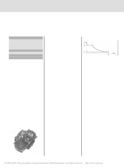
英文原文Applications4.1 IntroductionThis chapter demonstrates the scope of the method developed for the three-dimensional analysis of a screw compressor. The CFD package used in this case was COMET developed by ICCM GmbH Hamburg, today a part of CD-Adapco. The analysis of the flow and performance characteristics of a number of types of screw machines is performed to demonstrate a variety of parameters used for grid generation and calculation.The first example is concerned with a dry air screw compressor. A common compressor casing is used with two alternative pairs of rotors. The rotors have identical overall geometric properties but different lobe profiles. The application of the adaptation technique enables convenient grid generation for geometrically different rotors. The results obtained by three dimensional modelling are compared with those derived from a one-dimensional model, previously verified by comparison with experimental data..The relative advantages of each rotor profile are demonstrated.The second example shows the application of three dimensional flow analysis to the simulation of an oil injected air compressor. The results, thus obtained, are compared with test results obtained by the authors from a compressor and test rig, designed and built at City University. They are presented in the form of both integral parameters and a p-∂indicator diagram. Calculations based on the assumptions of the laminar flow are compared to those of turbulent flow. The effect of grid size on the results is also considered and shown here.The third example gives the analysis of an oil injected compressor in an ammonia refrigeration plant.This utilises the real fluid property subroutines in the process calculations and demonstrates the blow hole area and the leakage flow through the compressor clearances.The fourth example presents two cases, one of a dry screw compressor to show the influence of thermal expansion of the rotor on screw compressor performance and one of a high pressure oil-flooded screw compressor to show the influence of high pressure loads upon the compressor performance.4.2 Flow in a Dry Screw CompressorDry screw compressors are commonly used to produce pressurised air, free of any oil. A typical example of such a machine, similar in configuration to the compressor modelled, is shown in Figure 4-1. This is a single stage machine with 4 male and 6 female rotor lobes. The male and female rotor outer diameters are 142.380 mm and 135.820 mm respectively, while their centre lines are 108.4 mm apart. The rotor length to main diameter ratio l/d=1.77. Thus, the rotor length∂=248.40 is driven at a speed of 6000 rpm by an is 252.0 mm. The male rotor with wrap angleωelectric motor through a gearbox. The male and female rotors are synchronised through timinggears with the same ratio as that of the compressor rotor lobes i.e. 1.5. The female rotor speed is therefore 4000 rpm. The male rotor tip speed is then 44.7m/s, which is a relatively low value for a dry air compressor. The working chamber is sealed from its bearings by a combination of lip and labyrinth seals.Each rotor is supported by one radial and one axial bearing, on the discharge end, and one radial bearing on the suction end of the compressor. The bearings are loaded by a high frequency force, which varies due to the pressure change within the working chamber. Both radial and axial forces, as well as the torque change with a frequency of 4 times the rotational speed. This corresponds to 400Hz and coincides with the number of working cycles that occur within the compressor per unit time.Figure 4-1 Cross section of a dry screw compressorThe compressor takes in air from the atmosphere and discharges it to a receiver at a constant output pressure of 3 bar. Although the pressure rise is moderate, leakage through radial gaps of 150 m is substantial. In many studies and modelling ,procedures, volumetric losses are assumed to be a linear function of the cross sectional area and the square root of pressure difference, assuming that the interlobe clearance is kept more or less constant by the synchronising gears. The leakage through the clearances is then proportional to the clearance gap and the length of the leakage line. However, a large clearance gap is needed to prevent contact with the housing caused by rotor deformation due to the pressure and temperature changes within the working chamber. Hence, the only way to reduce leakage is to minimise the length of the sealing line. This can be achieved by careful design of the screw rotor profile. Although minimising,leakage is an important means of improving a screw compressor efficiency, it is not the only one. Another is to increase the flow area between the lobes and thereby increase the compressor flow capacity, thereby reducing the relative effect of leakage. Modern profile generation methods take these various effects into account by means of optimisation procedures which lead to enlargement of the male rotor interlobes and reduction in the female rotor lobes. Thefemale rotor lobes are thereby strengthened and their deformation thus reduced.To demonstrate the improvements possible from rotor profile optimisation, a three dimensional flow analysis has been carried out for two different rotor profiles within the same compressor casing, as shown in Figure 4-2. Both rotors are of the “N” type and rack generated.Figure 4-2…N‟ Rotors, Case-1 upper, Case-2 lowerCase 1 is an o lder design, similar in shape to SRM “D” rotors. Its features imply that there is a large torque on the female rotor, the sealing line is relatively long and the female lobes are relatively weak.Case 2, shown on the bottom of Figure 4-2, has rotors optimised for operating on dry air. The female rotor is stronger and the male rotor is weaker. This results in higher delivery, a relatively shorter sealing line and less torque on the female rotor. All these features help to improve screw compressor performance.The results of these two analyses are presented in the form of velocity distributions in the planesdefined by cross-sections A-A and B-B, shown in Figure 4-1.In the case of this study, the effect of rotor profile changes on compressor integral performance parameters can be predicted fairly accurately with one-dimensional models, even if some of the detailed assumptions made in such analytical models are inaccurate. Hence the integral results obtained from the three-dimensional analysis are compared with those from a one-dimensional model.4.2.1 Grid Generation for a Dry Screw CompressorIn Case-1, the rotors are mapped with 52 numerical cells along the interlobe on the male rotor and 36 cells along each interlobe on the female rotor in the circumferential direction. This gives 208 and 216 numerical cells respectively in the circumferential direction for the male and female rotors. A total of 6 cells in the radial direction and 97 cells in the axial direction is specified for both rotors. This arrangement results in a numerical mesh with 327090 cells for the entire machine. The cross section for the Case-1 rotors is shown in Figure 4-3. The female rotor is relatively thin and has a large radius on the lobe tip. Therefore, it is more easily mapped than in Case-2 where the tip radius is smaller, as shown in Figure 4-4.Figure 4-3 Cross section through the numerical mesh for Case-1 rotorsThe rotors in Case 2 are mapped with 60 cells along the male rotor lobe and 40 cells along the female lobe, which gives 240 cells along both rotors in the circumferential direction. In the radial direction, the rotors are mapped with 6 cells while 111 cells are selected for mapping along the rotor axis. Thus, the entire working chamber for this compressor has 406570 cells. In this case, different mesh sizes are applied and different criteria are chosen for the boundary adaptation of these rotors. The main adaptation criterion selected for the rotors is the local radius curvature with a grid point ratio of 0.3 to obtain the desired quality of distribution along the rotor boundaries. By this means, the more curved rotors are mapped with only a slight increase in the grid size to obtain a reasonable value of the grid aspect ratio. To obtain a similar grid aspect ratiowithout adaptation, 85 cells would have been required instead of 60 along one interlobe on the female rotor. This would give 510 cells in the circumferential direction on each of rotors. If the number of cells in the radial direction is also increased to be 8 instead of 6 but the number of cells along axis is kept constant, the entire grid would contain more then a million cells which would, in turn, result in a significantly longer calculation time and an increased requirement for computer memory.Figure 4-4 Cross section through the numerical mesh for Case-2 rotors4.2.2 Mathematical Model for a Dry Screw CompressorThe mathematical model used is based on the momentum, energy and mass conservation equations as given in Chapter 2. The equation for space law conservation is calculated in the model in order to obtain cell face velocities caused by the mesh movement. The system of equations is closed by Stoke‟s, Fourier‟s and Fick‟s laws and the equation of state for an ideal gas. This defines all the properties needed for the solution of the governing equations.4.2.3 Comparison of the Two Different Rotor ProfilesThe results obtained for both Case 1 and Case 2 compressors are presented here. To establish the full range of working conditions and to obtain an increase of pressure from 1 to 3 bars between the compressor suction and discharge, 15 time steps were required. A further 25 time steps were then needed to complete the full compressor cycle. Each time step needed about 30 minutes running time on an 800 MHz AMD Athlon processor. The computer memory required was about 400 MB. In Figure 4-5 the velocity vectors in the cross and axial sections are compared. The top diagram is given for Case-1 rotors and the bottom one for Case-2. As may be seen, the Case 2 rotors realised a smoother velocity distribution than the Case 1 rotors. This may have some advantage and could have increased the compressor adiabatic efficiency by reduction in flow drag losses. In both cases, recirculation within the entrapped working chamber occurs as consequence of the drag forces in the air as shown in the figure. On the other hand, different fluid flow patterns can be observed inthe suction port. The velocities within the working chambers and the suction and discharge ports are kept relatively low while the flow through the clearance gaps changes rapidly and easily reaches sonic velocity.Figure 4-5 Velocity field in the compressor cross section for Case1 and Case2 rotorsFigure 4-6 Velocity field in the compressor axial section for Case1 and Case2 rotors These differences are confirmed in the view of the vertical compressor section through the female rotor axis, shown in Figure 4-6. In Case 2, lower velocities are achieved not only in the working chamber but also in the suction and discharge ports. In the suction port, this is significant because of the fluid recirculation which appears at the end of the port. This recirculation causes losses which cannot be recovered later in the compression process. Therefore, many compressors are designed with only an axial port instead of both, radial and axial ports. Such a situation reduces suction dynamic losses caused by recirculation but, on the other hand, increases thevelocity in the suction chamber which in turn decreases efficiency. Some of these problems can beavoided only by the design of screw compressor rotors with larger lobes and a bigger swept volume and a shape which allows the suction process to be completed more easily. However, rotor profile design based on existing one-dimensional procedures neglects flow variations in the ports and hence is inferior for this purpose. In such cases, only a full three dimensional approach such as this, will be effective.中文译文应用4.1简介本章介绍了对螺杆压缩机的三维分析开发的方法的范围。