模具 外文翻译 英文文献 模具的发展与趋势
- 格式:doc
- 大小:118.00 KB
- 文档页数:27
注塑模具工艺中英文对照资料外文翻译文献附录2Integrated simulation of the injection molding process withstereolithography moldsAbstract Functional parts are needed for design verification testing, field trials, customer evaluation, and production planning. By eliminating multiple steps, the creation of the injection mold directly by a rapid prototyping (RP) process holds the best promise of reducing the time and cost needed to mold low-volume quantities of parts. The potential of this integration of injection molding with RP has been demonstrated many times. What is missing is the fundamental understanding of how the modifications to the mold material and RP manufacturing process impact both the mold design and the injection molding process. In addition, numerical simulation techniques have now become helpful tools of mold designers and process engineers for traditional injection molding. But all current simulation packages for conventional injection molding are no longer applicable to this new type of injection molds, mainly because the property of the mold material changes greatly. In this paper, an integrated approach to accomplish a numerical simulation of injection molding into rapid-prototyped molds is established and a corresponding simulation system is developed. Comparisons with experimental results are employed for verification, which show that the present scheme is well suited to handle RP fabricated stereolithography (SL) molds.Keywords Injection molding Numerical simulation Rapid prototyping1 IntroductionIn injection molding, the polymer melt at high temperature is injected into the mold under high pressure [1]. Thus, the mold material needs to have thermal and mechanical properties capable of withstanding the temperatures and pressures of the molding cycle. The focus of many studies has been to create theinjection mold directly by a rapid prototyping (RP) process. By eliminating multiple steps, this method of tooling holds the best promise of reducing the time and cost needed to createlow-volume quantities of parts in a production material. The potential of integrating injection molding with RP technologies has been demonstrated many times. The properties of RP molds are very different from those of traditional metal molds. The key differences are the properties of thermal conductivity and elastic modulus (rigidity). For example, the polymers used in RP-fabricated stereolithography (SL) molds have a thermal conductivity that is less than one thousandth that of an aluminum tool. In using RP technologies to create molds, the entire mold design and injection-molding process parameters need to be modified and optimized from traditional methodologies due to the completely different tool material. However, there is still not a fundamental understanding of h ow the modifications to the mold tooling method and material impact both the mold design and the injection molding process parameters. One cannot obtain reasonable results by simply changing a few material properties in current models. Also, using traditional approaches when making actual parts may be generating sub-optimal results. So there is a dire need to study the interaction between the rapid tooling (RT) process and material and injection molding, so as to establish the mold design criteria and techniques for an RT-oriented injection molding process.In addition, computer simulation is an effective approach for predicting the quality of molded parts. Commercially available simulation packages of the traditional injection molding process have now become routine tools of the mold designer and process engineer [2]. Unfortunately, current simulation programs for conventional injection molding are no longer applicable to RP molds, because of the dramatically dissimilar tool material. For instance, in using the existing simulation software with aluminum and SL molds and comparing with experimental results, though the simulation values of part distortion are reasonable for the aluminum mold, results are unacceptable, with the error exceeding 50%. The distortion during injection molding is due to shrinkage and warpage of the plastic part, as well as the mold. For ordinarily molds, the main factor is the shrinkage and warpage of the plastic part, which is modeled accurately in current simulations. But for RP molds, the distortion of the mold has potentially more influence, which have been neglected in current models. For instance, [3] used a simple three-step simulation process to consider the mold distortion, which had too much deviation.In this paper, based on the above analysis, a new simulation system for RP molds is developed. The proposed system focuses on predicting part distortion, which is dominating defect in RP-molded parts. The developed simulation can be applied as an evaluation tool for RP mold design and process opti mization. Our simulation system is verified by an experimental example.Although many materials are available for use in RP technologies, we concentrate on usingstereolithography (SL), the original RP technology, to create polymer molds. The SL process uses photopolymer and laser energy to build a part layer by layer. Using SL takes advantage of both the commercial dominance of SL in the RP industry and the subsequent expertise base that has been developed for creating accurate, high-quality parts. Until recently, SL was primarily used to create physical models for visual inspection and form-fit studies with very limited func-tional applications. However, the newer generation stereolithographic photopolymers have improved dimensional, mechanical and thermal properties making it possible to use them for actual functional molds.2 Integrated simulation of the molding process2.1 MethodologyIn order to simulate the use of an SL mold in the injection molding process, an iterative method is proposed. Different software modules have been developed and used to accomplish this task. The main assumption is that temperature and load boundary conditions cause significant distortions in the SL mold. The simulation steps are as follows:1T he part geometry is modeled as a solid model, which is translated to a file readable by the flow analysis package.2Simulate the mold-filling process of the melt into a pho topolymer mold, which will output the resulting temperature and pressure profiles.3Structural analysis is then performed on the photopolymer mold model using the thermal and load boundary conditions obtained from the previous step, which calculates the distortion that the mold undergo during the injection process.4If the distortion of the mold converges, move to the next step. Otherwise, the distorted mold cavity is then modeled (changes in the dimensions of the cavity after distortion), and returns to the second step to simulate the melt injection into the distorted mold.5The shrinkage and warpage simulation of the injection molded part is then applied, which calculates the final distor tions of the molded part.In above simulation flow, there are three basic simulation mod ules.2. 2 Filling simulation of the melt2.2.1 Mathematical modelingIn order to simulate the use of an SL mold in the injection molding process, an iterativemethod is proposed. Different software modules have been developed and used to accomplish this task. The main assumption is that temperature and load boundary conditions cause significant distortions in the SL mold. The simulation steps are as follows:1. The part geometry is modeled as a solid model, which is translated to a file readable by the flow analysis package.2. Simulate the mold-filling process of the melt into a photopolymer mold, which will output the resulting temperature and pressure profiles.3. Structural analysis is then performed on the photopolymer mold model using the thermal and load boundary conditions obtained from the previous step, which calculates the distortion that the mold undergo during the injection process.4. If the distortion of the mold converges, move to the next step. Otherwise, the distorted mold cavity is then modeled (changes in the dimensions of the cavity after distortion), and returns to the second step to simulate the melt injection into the distorted mold.5. The shrinkage and warpage simulation of the injection molded part is then applied, which calculates the final distortions of the molded part.In above simulation flow, there are three basic simulation modules.2.2 Filling simulation of the melt2.2.1 Mathematical modelingComputer simulation techniques have had success in predicting filling behavior in extremely complicated geometries. However, most of the current numerical implementation is based on a hybrid finite-element/finite-difference solution with the middleplane model. The application process of simulation packages based on this model is illustrated in Fig. 2-1. However, unlike the surface/solid model in mold-design CAD systems, the so-called middle-plane (as shown in Fig. 2-1b) is an imaginary arbitrary planar geometry at the middle of the cavity in the gap-wise direction, which should bring about great inconvenience in applications. For example, surface models are commonly used in current RP systems (generally STL file format), so secondary modeling is unavoidable when using simulation packages because the models in the RP and simulation systems are different. Considering these defects, the surface model of the cavity is introduced as datum planes in the simulation, instead of the middle-plane.According to the previous investigations [4–6], fillinggoverning equations for the flow and temperature field can be written as:where x, y are the planar coordinates in the middle-plane, and z is the gap-wise coordinate; u, v,w are the velocity components in the x, y, z directions; u, v are the average whole-gap thicknesses; and η, ρ,CP (T), K(T) represent viscosity, density, specific heat and thermal conductivity of polymer melt, respectively.Fig.2-1 a–d. Schematic procedure of the simulation with middle-plane model. a The 3-D surface model b The middle-plane model c The meshed middle-plane model d The display of the simulation result In addition, boundary conditions in the gap-wise direction can be defined as:where TW is the constant wall temperature (shown in Fig. 2a).Combining Eqs. 1–4 with Eqs. 5–6, it follows that the distributions of the u, v, T, P at z coordinates should be symmetrical, with the mirror axis being z = 0, and consequently the u, v averaged in half-gap thickness is equal to that averaged in wholegap thickness. Based on this characteristic, we can divide the whole cavity into two equal parts in the gap-wise direction, as described by Part I and Part II in Fig. 2b. At the same time, triangular finite elements are generated in the surface(s) of the cavity (at z = 0 in Fig. 2b), instead of the middle-plane (at z = 0 in Fig. 2a). Accordingly, finite-difference increments in the gapwise direction are employed only in the inside of the surface(s) (wall to middle/center-line), which, in Fig. 2b, means from z = 0 to z = b. This is single-sided instead of two-sided with respect to the middle-plane (i.e. from the middle-line to two walls). In addition, the coordinate system is changed from Fig. 2a to Fig. 2b to alter the finite-element/finite-difference scheme, as shown in Fig. 2b. With the above adjustment, governing equations are still Eqs. 1–4. However, the original boundary conditions inthe gapwise direction are rewritten as:Meanwhile, additional boundary conditions must be employed at z = b in order to keep the flows at the juncture of the two parts at the same section coordinate [7]:where subscripts I, II represent the parameters of Part I and Part II, respectively, and Cm-I and Cm-II indicate the moving free melt-fronts of the surfaces of the divided two parts in the filling stage.It should be noted that, unlike conditions Eqs. 7 and 8, ensuring conditions Eqs. 9 and 10 are upheld in numerical implementations becomes more difficult due to the following reasons:1. The surfaces at the same section have been meshed respectively, which leads to a distinctive pattern of finite elements at the same section. Thus, an interpolation operation should be employed for u, v, T, P during the comparison between the two parts at the juncture.2. Because the two parts have respective flow fields with respect to the nodes at point A and point C (as shown in Fig. 2b) at the same section, it is possible to have either both filled or one filled (and one empty). These two cases should be handled separately, averaging the operation for the former, whereas assigning operation for the latter.3. It follows that a small difference between the melt-fronts is permissible. That allowance can be implemented by time allowance control or preferable location allowance control of the melt-front nodes.4. The boundaries of the flow field expand by each melt-front advancement, so it is necessary to check the condition Eq. 10 after each change in the melt-front.5. In view of above-mentioned analysis, the physical parameters at the nodes of the same section should be compared and adjusted, so the information describing finite elements of the same section should be prepared before simulation, that is, the matching operation among the elements should be preformed.Fig. 2a,b. Illustrative of boundary conditions in the gap-wise direction a of the middle-plane model b of thesurface model2.2.2 Numerical implementationPressure field. In modeling viscosity η, which is a function of shear rate, temperature and pressure of melt, the shear-thinning behavior can be well represented by a cross-type model such as:where n corresponds to the power-law index, and τ∗ characterizes the shear stress level of the transition region between the Newtonian and power-law asymptotic limits. In terms of an Arrhenius-type temperature sensitivity and exponential pressure dependence, η0(T, P) can be represented with reasonable accuracy as follows:Equations 11 and 12 constitute a five-constant (n, τ∗, B, Tb, β) representation for viscosity. The shear rate for viscosity calculation is obtained by:Based on the above, we can infer the following filling pressure equation from the governing Eqs. 1–4:where S is calculated by S = b0/(b−z)2η d z. Applying the Galerkin method, the pressure finite-element equation is deduced as:where l_ traverses all elements, including node N, and where I and j represent the local node number in element l_ corresponding to the node number N and N_ in the whole, respectively. The D(l_) ij is calculated as follows:where A(l_) represents triangular finite elements, and L(l_) i is the pressure trial function in finite elements.Temperature field. To determine the temperature profile across the gap, each triangular finite element at the surface is further divided into NZ layers for the finite-difference grid.The left item of the energy equation (Eq. 4) can be expressed as:where TN, j,t represents the temperature of the j layer of node N at time t.The heat conduction item is calculated by:where l traverses all elements, including node N, and i and j represent the local node number in element l corresponding to the node number N and N_ in the whole, respectively.The heat convection item is calculated by:For viscous heat, it follows that:Substituting Eqs. 17–20 into the energy equation (Eq. 4), the temperature equation becomes:2.3 Structural analysis of the moldThe purpose of structural analysis is to predict the deformation occurring in the photopolymer mold due to the thermal and mechanical loads of the filling process. This model is based on a three-dimensional thermoelastic boundary element method (BEM). The BEM is ideally suited for this application because only the deformation of the mold surfaces is of interest. Moreover, the BEM has an advantage over other techniques in that computing effort is not wasted on calculating deformation within the mold.The stresses resulting from the process loads are well within the elastic range of the mold material. Therefore, the mold deformation model is based on a thermoelastic formulation. The thermal and mechanical properties of the mold are assumed to be isotropic and temperature independent.Although the process is cyclic, time-averaged values of temperature and heat flux are used for calculating the mold deformation. Typically, transient temperature variations within a mold have been restricted to regions local to the cavity surface and the nozzle tip [8]. The transients decay sharply with distance from the cavity surface and generally little variation is observed beyond distances as small as 2.5 mm. This suggests that the contribution from the transients to the deformation at the mold block interface is small, and therefore it is reasonable to neglect the transient effects. The steady state temperature field satisfies Laplace’s equation 2T = 0 and the time-averaged boundary conditions. The boundary conditions on the mold surfaces are described in detail by Tang et al. [9]. As for the mechanical boundary conditions, the cavity surface is subjected to the melt pressure, the surfaces of the mold connected to the worktable are fixed in space, and other external surfaces are assumed to be stress free.The derivation of the thermoelastic boundary integral formulation is well known [10]. It is given by:where uk, pk and T are the displacement, traction and temperature,α, ν represent the thermal expansion coefficient and Poisson’s ratio of the material, and r = |y−x|. clk(x) is the surfacecoefficient which depends on the local geometry at x, the orientation of the coordinate frame and Poisson’s ratio for the domain [11]. The fundamental displacement ˜ulk at a point y in the xk direction, in a three-dimensional infinite isotropic elastic domain, results from a unit load concentrated at a point x acting in the xl direction and is of the form:where δlk is the Kronecker delta function and μ is the shear modulus of the mold material.The fundamental traction ˜plk , measured at the point y on a surface with unit normal n, is:Discretizing the surface of the mold into a total of N elements transforms Eq. 22 to:where Γn refers to the n th surface element on the domain.Substituting the appropriate linear shape functions into Eq. 25, the linear boundary element formulation for the mold deformation model is obtained. The equation is applied at each node on the discretized mold surface, thus giving a system of 3N linear equations, where N is the total number of nodes. Each node has eight associated quantities: three components of displacement, three components of traction, a temperature and a heat flux. The steady state thermal model supplies temperature and flux values as known quantities for each node, and of the remaining six quantities, three must be specified. Moreover, the displacement values specified at a certain number of nodes must eliminate the possibility of a rigid-body motion or rigid-body rotation to ensure a non-singular system of equations. The resulting system of equations is assembled into a integrated matrix, which is solved with an iterative solver.2.4 Shrinkage and warpage simulation of the molded partInternal stresses in injection-molded components are the principal cause of shrinkage and warpage. These residual stresses are mainly frozen-in thermal stresses due to inhomogeneous cooling, when surface layers stiffen sooner than the core region, as in free quenching. Based onthe assumption of the linear thermo-elastic and linear thermo-viscoelastic compressible behavior of the polymeric materials, shrinkage and warpage are obtained implicitly using displacement formulations, and the governing equations can be solved numerically using a finite element method.With the basic assumptions of injection molding [12], the components of stress and strain are given by:The deviatoric components of stress and strain, respectively, are given byUsing a similar approach developed by Lee and Rogers [13] for predicting the residual stresses in the tempering of glass, an integral form of the viscoelastic constitutive relationships is used, and the in-plane stresses can be related to the strains by the following equation:Where G1 is the relaxation shear modulus of the material. The dilatational stresses can be related to the strain as follows:Where K is the relaxation bulk modulus of the material, and the definition of α and Θ is:If α(t) = α0, applying Eq. 27 to Eq. 29 results in:Similarly, applying Eq. 31 to Eq. 28 and eliminating strain εxx(z, t) results in:Employing a Laplace transform to Eq. 32, the auxiliary modulus R(ξ) is given by:Using the above constitutive equation (Eq. 33) and simplified forms of the stresses and strains in the mold, the formulation of the residual stress of the injection molded part during the cooling stage is obtain by:Equation 34 can be solved through the application of trapezoidal quadrature. Due to the rapid initial change in the material time, a quasi-numerical procedure is employed for evaluating the integral item. The auxiliary modulus is evaluated numerically by the trapezoidal rule.For warpage analysis, nodal displacements and curvatures for shell elements are expressed as:where [k] is the element stiffness matrix, [Be] is the derivative operator matrix, {d} is the displacements, and {re} is the element load vector which can be evaluated by:The use of a full three-dimensional FEM analysis can achieve accurate warpage results, however, it is cumbersome when the shape of the part is very complicated. In this paper, a twodimensional FEM method, based on shell theory, was used because most injection-molded parts have a sheet-like geometry in which the thickness is much smaller than the other dimensions of the part. Therefore, the part can be regarded as an assembly of flat elements to predict warpage. Each three-node shell element is a combination of a constant strain triangular element (CST) and a discrete Kirchhoff triangular element (DKT), as shown in Fig. 3. Thus, the warpage can be separated into plane-stretching deformation of the CST and plate-bending deformation of the DKT, and correspondingly, the element stiffness matrix to describe warpage can also be divided into the stretching-stiffness matrix and bending-stiffness matrix.Fig. 3a–c. Deformation decomposition of shell element in the local coordinate system. a In-plane stretchingelement b Plate-bending element c Shell element3 Experimental validationTo assess the usefulness of the proposed model and developed program, verification is important. The distortions obtained from the simulation model are compared to the ones from SL injection molding experiments whose data is presented in the literature [8]. A common injection molded part with the dimensions of 36×36×6 mm is considered in the experiment, as shown in Fig. 4. The thickness dimensions of the thin walls and rib are both 1.5 mm; and polypropylene was used as the injection material. The injection machine was a production level ARGURY Hydronica 320-210-750 with the following process parameters: a melt temperature of 250 ◦C; an ambient temperature of 30 ◦C; an injection pressure of 13.79 MPa; an injection time of 3 s; and a cooling time of 48 s. The SL material used, Dupont SOMOSTM 6110 resin, has the ability to resist temperatures of up to 300 ◦C temperatures. As mentioned above, thermal conductivity of the mold is a major factor that differentiates between an SL and a traditional mold. Poor heat transfer in the mold would produce a non-uniform temperature distribution, thus causing warpage that distorts the completed parts. For an SL mold, a longer cycle time would be expected. The method of using a thin shell SL mold backed with a higher thermal conductivity metal (aluminum) was selected to increase thermal conductivity of the SL mold.Fig. 4. Experimental cavity modelFig. 5. A comparison of the distortion variation in the X direction for different thermal conductivity; where “Experimental”, “present”, “three-step”, and “conventional” mean the results of the experimental, the presented simulation, the three-step simulation process and the conventional injection molding simulation, respectively.Fig. 6. Comparison of the distortion variation in the Y direction for different thermal conductivitiesFig. 7. Comparison of the distortion variation in the Z direction for different thermal conductivitiesFig. 8. Comparison of the twist variation for different thermal conductivities For this part, distortion includes the displacements in three directions and the twist (the difference in angle between two initially parallel edges). The validation results are shown in Fig.5 to Fig. 8. These figures also include the distortion values predicted by conventional injection molding simulation and the three-step model reported in [3].4 ConclusionsIn this paper, an integrated model to accomplish the numerical simulation of injection molding into rapid-prototyped molds is established and a corresponding simulation system is developed. For verification, an experiment is also carried out with an RPfabricated SL mold.It is seen that a conventional simulation using current injection molding software breaks down for a photopolymer mold. It is assumed that this is due to the distortion in the mold caused by the temperature and load conditions of injection. The three-step approach also has much deviation. The developed model gives results closer to experimental.Improvement in thermal conductivity of the photopolymer significantly increases part quality. Since the effect of temperature seems to be more dominant than that of pressure (load), an improvement in the thermal conductivity of the photopolymer can improve the part quality significantly.Rapid Prototyping (RP) is a technology makes it possible to manufacture prototypes quickly and inexpensively, regardless of their comp lexity. Rapid Tooling (RT) is the next step in RP’s steady progress and much work is being done to obtain more accurate tools to define the parameters of the process. Existing simulation tools can not provide the researcher with a useful means of studying relative changes. An integrated model, such as the one presented in this paper, is necessary to obtain accurate predictions of the actual quality of final parts. In the future, we expect to see this work expanded to develop simulations program for injection into RP molds manufactured by other RT processes.References1. Wang KK (1980) System approach to injection molding process. Polym-Plast Technol Eng 14(1):75–93.2. Shelesh-Nezhad K, Siores E (1997) Intelligent system for plastic injection molding process design. J Mater Process Technol 63(1–3):458–462.3. Aluru R, Keefe M, Advani S (2001) Simulation of injection molding into rapid-prototyped molds. Rapid Prototyping J 7(1):42–51.4. Shen SF (1984) Simulation of polymeric flows in the injection molding process. Int J Numer Methods Fluids 4(2):171–184.5. Agassant JF, Alles H, Philipon S, Vincent M (1988) Experimental and theoretical study of the injection molding of thermoplastic materials. Polym Eng Sci 28(7):460–468.6. Chiang HH, Hieber CA, Wang KK (1991) A unified simulation of the filling and post-filling stages in injection molding. Part I: formulation. Polym Eng Sci 31(2):116–124.7. Zhou H, Li D (2001) A numerical simulation of the filling stage in injection molding based on a surface model. Adv Polym Technol 20(2):125–131.8. Himasekhar K, Lottey J, Wang KK (1992) CAE of mold cooling in injection molding using a three-dimensional numerical simulation. J EngInd Trans ASME 114(2):213–221.9. Tang LQ, Pochiraju K, Chassapis C, Manoochehri S (1998) Computeraided optimization approach for the design of injection mold cooling systems. J Mech Des, Trans ASME 120(2):165–174.10. Rizzo FJ, Shippy DJ (1977) An advanced boundary integral equation method for three-dimensional thermoelasticity. Int J Numer Methods Eng 11:1753–1768.11. Hartmann F (1980) Computing the C-matrix in non-smooth boundary points. In: New developments in boundary element methods, CML Publications, Southampton, pp 367–379.12. Chen X, Lama YC, Li DQ (2000) Analysis of thermal residual stress in plastic injection molding. J Mater Process Technol 101(1):275–280.13. Lee EH, Rogers TG (1960) Solution of viscoelastic stress analysis problems using measured creep or relaxation function. J Appl Mech 30(1):127–134.14. Li Y (1997) Studies in direct tooling using stereolithography. Dissertation, University of Delaware, Newark, DE..。
Figure 1. Organization of the IKEM Project2 Intelligent Mold Design ToolThe mold design tool in its basic form is a Visual Basic application taking input from a text file that contains information about the part and a User Input form. The text file contains information about the part geometry parsed from a Pro/E information file. The input is used to estimate the dimensions of mold and various other features.2.1 Literature ReviewDesign of molds is another stage of the injection molding process where the experience of an engineer largely helps automate the process and increase its efficiency. The issue that needs attention is the time that goes into designing the molds. Often, design engineers refer to tables and standard handbooks while designing a mold, which consumes lot of time. Also, a great deal of time goes into modeling components of the mold in standard CAD software. Differentresearchers have dealt with the issue of reducing the time it takes to design the mold in different ways. Koelsch and James have employed group technology techniques to reduce the mold design time. A unique coding system that groups a class of injection molded parts, and the tooling required ininjection molding is developed which is general and can be applied to other product lines.A software system to implement the coding system has also been developed. Attempts were also directed towards the automation of the mold design process by capturing experience and knowledge of engineers in the field. The development of a concurrent mold design system is one such approach that attempts to develop a systematic methodology for injection mold design processes in a concurrent engineering environment. The objective of their research was to develop a mold development process that facilitates concurrent engineering-based practice, andFigure 2. Organization of the Mold Design Module.While most of the input, like the number of cavities, cavity image dimensions, cycle time are based on the client specifications, other input like the plasticizing capacity, shots per minute etc., can be obtained from the machine specifications. The output of the application contains mold dimensions and other information, which clearly helps in selecting the standard mold base from catalogs. Apart from the input and output, the Figure 2 also shows the various modules that produce the final output.2.5 Framing rulesAt this stage, the expert’s knowledge is represented in the form of multiple If-Then statements. The rules may be representations of both qualitative and quantitative knowledge. By qualitative knowledge, we mean deterministic information about a problem that can be solved computationally. By qualitative we mean information that is not deterministic, but merely followed as a rule based on previous cases where the rule has worked. A typical rule is illustrated below:If Material = “Acetal” AndRunner Length <= 3 AndRunner Length > 0 ThenRunner Diameter =0.062End IfWhen framing the rules it is important that we represent the information in a compact way while avoiding redundancy, incompleteness and inconsistency. Decision tables help take care of all the above concerns by checking for redundancy and comprehensive expression of the problem statement. As an example, in the process of selecting an appropriate mold base, the size of mold base depends on the number of cavities and inserts. To ensure that all possible combinations of。
外文原文Abstract:Die designing is a demanding and hard work.To design a separate die for each product is time consuming and expensive task.This paper presents an idea of sets of standard reference dies.it gives a concept of flexible die designing using a reference standard die designed in a popular commercial CAD/CAM software—Pro/Engineer.Rather than designing a separate die for each part,just update the die design by selecting the die dimensions as required.The use of this concept will prove to reduce time and cost of product in manufacturing industry.Key words:die;flexible die designing system ;standardization;Pro/E;secondary developmentAt present, the industrial developed countries and regions in the mold industry has been gradually standardize and serialization. In China, although the majority die within the enterprises have business standards, but generally not high degree of standardization, standardization of stamping die in the die-limited parts of the parts. To achieve real savings stamping die design time and shorten the processing cycle, cost savings, reduce design and manufacturing staff workload purposes, it needs to develop a flexible stamping die design system. At the same time, stamping die serialization of the scope of standardization and can not be confined to die-part of the fixed panels, boards, the top plate unloading device commonly used components such as stamping or even die structure, we should achieve serialization and standardization.As CAD / CAM technology in the design and manufacture die in the course of extensive application, it should first be standardized stamping die from the CAD system began. Some large-scale commercialization of the CAD / CAM software, such as Pro / E, UG, and so on. Have developed a specialized injection mold design package. And stamping die design for the special software, users need to be developed.l The application tools Pro / E in stamping die design flexibility in the system developmentPro / Engineer by the United States has developed a set of PTC CAD / cAM / CAE software. Pro / E using a single database And feature-based, the design parameters of the model, provides users with 1 The development is very convenient for stamping die flexible system of tools juice1.1 Family TableFanaily Fable known as the Family Table, the structure used to create the same or similar parts of the size and characteristics of the standardized database tables, is devoted to the establishment of a standard parts library tool. The use of the formerfirst family table to create a generic representation of the components (the generic), according to the need to target and then added to the family table a series of management.Family sheet management can be the object of a size (dimension), features (feature), parameters (parameter) and assembly parts (component), and so on.A family table can have multiple levels, that is a generic parts can contain multiple sub-components (instance, also known as examples), and each Instance can contain their own Sub Instance. Discharge screw (stripper-bolt) the family table structure as shown in Figure 1.Figure 1 Family Table hierarchy1.2 RelationsRelations (relations) between mathematics and procedures, including grammar, and its main role is to be part or assembly of the relevance of the data by size symbols, and other parameters of grammar (syntax) to establish mathematical formula to meet the design requirements. Pro / E system of relations can be found in Sketch, Feature, Part and in the Assembly. Simple sentence, judgement and sentence is to establish relations of common format. Simple sentence that a simple mathematical relationship between the size of direct response associated situation. The use of simple format, such as d6 = L. BP 1 2 * d3. Judgement on the sentence for certain occasions, by specifying conditions to express design intent, grammar structure: "IF… ENDIF" or "IF… ELSE… ENDIF" in the "ELSE… ENDIF" between conditional statements can be multi-nested. Relations in the standardization and flexible stamping die design system in the building process plays a very important role, it has decided to parts of the geometric shape and characteristics of relations between the digital Xiao, partsrelations between the assembly and parts assembly in the presence of middle - A number of features.1.3 Pro/ProgramPro / Program (program) is the Pro / E of a procedural tool, similar to its grammar VBA and Office software in the Macro (Acer). When users use of Pro / engineer to design .The product of various kinds of information to document the format will be recorded. Through the Pro / Progran document editing, can be achieved on the characteristics of the hide, delete and re-order the assembly of components to add and replacement operation. These features stamping dies for the establishment of standard parts library, standards and flexible design structure of the system is very useful.Program files in the structure can be broadly classified into the title, set of parameters relationship, to add features (parts) and updating the quality attributes, such as five parts. In "INPUT… END INPUT" Xiao located between the parameters of the "RE1 ATIONS… ENDREALATIONS" relations between the various add in the "ADD… END ADD" and added features (part module) or parts (assembly module). Pro / Program provides three types of parameters: NUMBER (numerical) STRING (string) and YES-NO (it).2. Standards moldbase of the development2.1 Standards moldbase Classification and organizationsDie-stamping die is an important part. The typical model-there are three types: rear-guided-mode (back pillar sets), the middle-guided-mode (center pillar sets) and the guided-mode-angle (diagonal pillarsets). Each type of die-also includes a variety of specifications. According to Die boundary demarcation size, rear-guided, in a L ×B-22 specifications, D0 specifications 6 (L = B), middle-guided, in the nine-D0 specifications, the guided-mode-Kok L × B specifications 7 [2-3].In order to facilitate the management and data calls, the standard mode of the directory of the best-established in the Pro / E installation directory. As three categories-the larger structural differences, it may die-the root of the establishment of three other subdirectories, each subdirectory contains all the component parts-mode, and each type of parts can be adopted Pro / E Software for the family table, and toolssuch as the establishment of standard procedures for the database.2.2 Standards moldbase library buildingDie-stamping die from the main mode on the Block (upper.shoe), nder-Block (1 ower.shoe), I. column (guide.pillar) and I. Case (guidebushing), and other components. In order to make structural integrity of mold, can also die stalk (shank) assembly to die-in. Here are rear-die I.Establishment of the standard method.First of all the various components to create three-dimensional model, and then the standard manual data in the table a series of symbolic dimension added to the group on January 1 Editor (can also use Excel for editing). Add in the size of symbols, Size will be the best symbol to revise the manual and the size of the same symbol. Because people can not distinguish between Table Capitalization is, when both the same size letters, proposed to use capital letters to distinguish between pairs of characters, such as that for the d D, and D that will become a DD.Standard on two-Block: When the L ×B> 200 mm ×160 mn-i have installed Boss, and when L × B is less than or equal to the scope of non-installation of Boss, shown in Figure 2. Determine whether Boss in two ways: one way is to use Family Table, will generate the Boss Extrude Offset two characteristics and the way to Feature added to the family table, and in these two characteristics of the list Enter in the "Y" or "N", to determine the specifications of a certain mode on the Block, whether these two features; Another method is to find these two features in the Pro / Program in the location and characteristics of the process to add Extrude His statement before the judge "IF L> 200 1 B> 160", adding the Offset characteristics of the procedures used "END IF" the end of judgement.Figure2. die on the ground in two types2.3 The establishment of Standards moldbase forIn Pro / Assembly in the same module can be generated by the use of family die-standard database. Family structure in the assembly, when selected COrnponent, select the mode of all the parts-and enter a different group in the table-model specifications required by the standards of sub-components of the name, as shown in Figure 3.Figure 3 rear-guided, in the standard mode of Family TableCommon mode handles four types: pressure-in-stalk, the flange-stalk, Screw-mode and floating stems die stalk. If the four types of module assembly to handle all the common-mode model (Figure 3 in the assembly only two kinds), in the group table by the need to enter the module handles parts of the name, set the parameters of INPUT, with Regenerate Called when the parameters of renewable order to choose the mode of different types of handles. Of course, people can also die of the table do not have to handle characters with "N" to curb, as shown in Figure 3-mode system is used in this method.3 The development of standard stamping die3.1 The typical combination of stamping dieStamping die in the larger structural differences and establish flexible stamping die design systems using the best combination of the typical mold. Use of combinations to determine the structure of the typical mold of the structure, and thus determine the composition of the various components die sizes and assembly relations. Commonly used combination of stamping die typical structure: a fixed combinationof unloading, Tanya unloading combinations, composite model portfolio, such as plate-portfolio. Mold can not be separated from the structure of ISO standardization of parts, in the Pro / Engineer Dies in the standardization of parts can be used in the design of the bottom-up approach can also be used top-down design.3.2 die in the process of assembling data transferBecause of complicated, so stamping die by the standardization of the factors to consider-Modulus than standardized by many more factors to consider, one of the most important factor is the size of the correlation between the components. In the mold of a standard combination, assembly and components, parts and components between the need for data transmission, and in the Pro / Assembly can be very easy to achieve this objective.3.2.1 by the assembly of components to the data transferPro / Program can use the assembly EXECUTE statement will be down the parameters in a sub-assembly or parts delivery, the use of syntax is as follows: EXECUTE PART / ASSEMBLY file name components or sub-assembly of the parameters in the assembly of = END EXECUTE EXECUTE statement parameters can not leapfrog data transmission, not by the assembly to sub-assembly of components in the direct transmission of data.3.2.2 data transfer between the componentsWhen added to the assembly of components are in a Id, it can complete the assembly of components between the data transfer. Id assembly of components, can be used in the menu RELATIONs Session Id command to query. Figure 4 is the combination of Tanya discharge standards in the spring of unloading assembly diagram. As assembly to die in the spring have a pre-compression and thus the length of its assembly (Hs) are no longer equal to the length of freedom (H.). In determining H, you can use the following mathematical relationship:Hs:38= L:32一tbp:0In this way can always guarantee equal to the length of spring assembly from the surface to Dianban discharge board under the surface height, thus eliminating the relevant parts were replaced after the size of Laws. In the design of this mold is very practical, because the mold assembly in a similar situation there are many. Again, in determining the discharge screw on the seat-hole diameter (dI34), they can use thefollowing mathematical relationship:d134:8=D:32+2This Id, established by the mathematical relationship between the need to use Regenerate order to take effect, so different parts on the size of the location of as little as possible in this way, so as not to die in the initial call model will appear at the wrong result will be displayed. But if the parts in between and parameters to transfer data, the location of the various components of size parameters to create a mathematical relationship, the trouble can be avoided.3.2.3 standard replacement partsFamily Table used to establish the standard parts can lookup. inst Replacement statement. Lookup inst allows users to find the standard parts that match the sub-components, if not find the results, then return to a generic [4 J.Lookup.inst :lookup inst(generic—name,match-mode,paramnamel,match—valuel,param-name2,match—value2…)One match. preferred mode of three, representing different meanings: one is to find parameters of less than or equal to find the value of components; parameter values 0 to find an exact match to find value of the sub-components; to find parameters of greater than or equal to find value The sub-components.3.3 structure of the assemblyDie parts to complete the establishment and rationalize the assembly relations between the components, you can generate mold assembly model. Figure 5 for the development of the author Tanya unloading combination of specifications for the 200 mm × 160 mm of die structure (omit all the characteristics of thread).3.4 stamping die callStamping die in the Pro / Assembly call directly, but also can be used Pro / TOOLKIT development of visual user interface to call. Pro / TOOLKIT Pro Ecuador is the second development system software package, its main purpose is to allowusers or third parties through the expansion of C code Pro / E function, based on the development of Pro / E system of application modules to meet user Special needs. Pro/T00LKIT use of the UI dialog, the menu VC + + and Visual Interface technology, designed to facilitate flexible and practical stamping die design system for interactive interface. Use interface called the structure of various stamping dies, the choice of different specifications of the parts, enter a different parameters to determine sheet parameters as well as their positioning in the mold, and further in the system design punch, die and other structures, Thus greatly enhance the efficiency of stamping die design.4 ConclusionSince stamping process a wide range of complex processes, and the shape of various parts die, stamping dies in achieving standardization and development of flexible design system and the process is very complicated, but flexible stamping die design system of stamping die CAD is to improve the level of the cornerstones . Pro / E powerful components, the assembly of the criteria for the establishment of the functions of stamping dies for the standardization and flexible design of the feasibility of developing systems to provide a strong guarantee. In the development of flexible design system, should ingenious application of Pro / E software provided by an effective tool, considering the different types of standard structural composition of the assembly relations. Between the parts and components meet requirements of size structure changes, and the best use RELATIONS Pro / Program prepared by the mathematical relations systems and procedures to increase the flexibility and practicality. Die flexible design and application development system to avoid a mold designers unnecessary duplication of labor, so that the programme will focus on the concept, process optimization, and other creative work, thus mold the rapid design and production standards have a practical application Significance.外文资料翻译译文摘要:模具设计是一个苛刻的辛勤工作。
模具行业英语Mold making is an intricate art that requires precision and a keen eye for detail. The process begins with a design, which is then meticulously crafted into a mold that can withstand the pressures of manufacturing.In the world of molds, materials are carefully selected to ensure the durability and functionality of the final product. Metals like steel and aluminum are popular choices due to their strength and heat resistance.The molding process itself is a symphony of heat and pressure. Molten materials are poured into the mold, taking shape as they cool and solidify. This transformation is a testament to the craftsmanship involved in the industry.Advancements in technology have revolutionized the mold-making industry. Computer-aided design (CAD) and computer-aided manufacturing (CAM) have streamlined the process, allowing for more complex and precise molds to be created.Sustainability is a growing concern in the industry, with efforts being made to reduce waste and energy consumption. Eco-friendly materials and processes are increasingly sought after to minimize the environmental impact.Quality control is paramount in the mold industry. Each mold is inspected for any imperfections that could affect thefinal product. This attention to detail ensures that only the highest quality molds are used in production.Training and education are vital for those entering the mold-making field. Apprenticeships and specialized courses provide the necessary skills and knowledge to excel in this specialized industry.The future of the mold industry is promising, with innovations in materials and technology driving its growth. As products become more sophisticated, so too does the need for molds that can meet these evolving demands.。
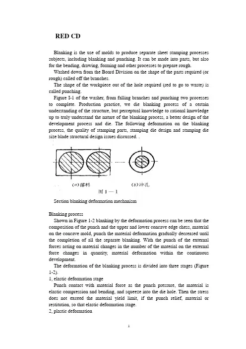
RED CDBlanking is the use of molds to produce separate sheet stamping processes subjects, including blanking and punching. It can be made into parts, but also for the bending, drawing, forming and other processes to prepare rough. Washed down from the Board Division on the shape of the parts required (or rough) called off the branches.The shape of the workpiece out of the hole required (red to go to waste) is called punching.Figure I-1 of the washer, from falling branches and punching two processes to complete. Production practice, we die blanking process of a certain understanding of the structure, but perceptual knowledge to rational knowledge up to truly understand the nature of the blanking process, a better design of the development process and die. The following deformation on the blanking process, the quality of stamping parts, stamping die design and stamping die size blade structural design issues discussed. .Section blanking deformation mechanismBlanking processShown in Figure 1-2 blanking by the deformation process can be seen that the composition of the punch and the upper and lower concave edge chess, material on the concave mold, punch the material deformation gradually decreased until the completion of all the separate blanking. With the punch of the external forces acting on material changes in the number of the material on the external force changes in quantity, material deformation within the continuous development.The deformation of the blanking process is divided into three stages (Figure 1-2).1, elastic deformation stagePunch contact with material force as the punch pressure, the material is elastic compression and bending, and squeeze into the die hole. Then the stress does not exceed the material yield limit, if the punch relief, material or restitution, so that elastic deformation stage.2, plastic deformationPunch to pressure, the stress reaches the yield limit of material, some metal is squeezed into the die hole, producing plastic shear deformation, are shining maggot cut surface. For convex, concave feel there is room between the depression, it is the plastic shear deformation is also accompanied by the bending and stretching.3, fault isolation stageMaterials continue to increase external and internal stress increasing, convex, because the incision die stress concentration, shear strength over the first internal stress, micro-crack appears. Mold continuing under pressure, convex, concave mold cavities of the micro-crack edge to the material constantly within the share capital, then pulled off material separation. Such as convex, concave die gap was reasonable, the upper and lower crack coincide with each other. ' Stress and strainFurther analysis of blanking time of stress and strain state of deformation zone and help to the understanding of the blanking process. Die and punch in the edge of the joint line to take 'cell body, "whose stress-strain diagram shown in Figure 1-3. Can be seen from the figure, it seemsMetal fracture line AB that is cutting edge on-line) at 45 degrees. The main uranium direction I was pulling stress and tensile deformation, tensile stress the goldIs a fiber elongation; its vertical axis 2 is the compression stress direction and compressive deformation, the fiber extrusion pressure; in the tangential direction of the stress and strain is very small, negligible; and principal stress direction at 45. Direction to the direction of maximum shear stress between the punch and die clearance, elongation and tear off the metal, resulting in broken fracture surface roughness, and with a burr.The process can also blanking blanking force deformation curves of the figure is confirmed. Figure 2-9 (materials), is punching a 3 mm thick material punching power and punch of the curve. Can be seen from the diagram:In the process of blanking blanking force size is constantly changing. AB section of the equivalent of punching the elastic deformation stage, BC Section for the plastic deformation stage. When the material internal stress to shear strength began to crack when the material, CD segment for the crack propagation until the material isolated rupture in order teams, DE Dan launch materials introduced die mouth piece.Cut section ofSee Figure 2-10The deformation process of blanking the red plant parts are not smooth vertical section, the section has three areas, namely, with rounded corners, bright band and the fault zone.Rounded band is in the process of blanking the beginning of plastic deformation. Since the bending and stretching metal fibers formed, soft material than hard Branch rounded large.Light zone is the second phase of deformation produced plastic shear deformation of metal forming, has a smooth vertical surface, bright band of the entire cross section of 1 / 2 to 1 / 3 of the light bandwidth of soft materials, hard materials with a narrow bright . With the mechanical properties of materials, space, mold structural changes.Fault is equivalent to the third stage of the blanking process, mainly due to the role of tensile stress, the continuous expansion of China cracks down payments second fiber extension, so a very rough surface is not smooth, and there Liaoduo. In the section on the same punch with these characteristics, but the distribution of the three regions opposite position and blanking.Blanking addition to drag a section of rough dimensions, there are points dome curved, not flat, face a burr, so blanking requirements apply only to an Blanking.Section Drawing gapBlanking time requires not only the shape of call times out of line drawing parts, there should be a certain quality requirements, quality of stamping pieces is cut surface quality, dimensional accuracy and form error. Cut surface should be flat, smooth, no crack and tear, mezzanine and other defects, glitches small parts, the surface should be flat as possible, that is a small vaulted arch, size, degree of precision required to ensure the drawings do not exceed the tolerance range.Factors that affect the quality of stamping pieces range from the actual production that, convex, concave die gap size and power uniformity, pattern edge state, the mold structure and manufacturing precision, quality materials, and so on all affect Na blanking. However, we must find out which plays a decisive role in the quality of the blanking factor. Gap is a.Section 1 on the quality of blankingComparison of straight, smooth, and no burr. In this case, the quality of parts that is a good cross section.When the gap is too hours of up and down the crack does not coincide with each other. . . .When the gap is too large cracks do not overlap. . . . (See 2-11)If the gap uneven distribution of local spikes. . . Uneven wear, increased, so clearance is not only to use reasonable and die on the manufacture and adjustment of space even when the guarantee.2. Gap on the Dimensional AccuracyBlanking Stamping dimensional accuracy refers to the actual size and nominal size of the margin, the difference is smaller the higher the precision.difference between living in two areas packet error, one blanking punch or die with the size of the deviation, one mold itself create bias.Blanking and convex, die size deviation was mainly due to:Workpiece (waste) from the concave mold release, as caused by elastic recovery. Deviation may be positive, it could be negative.Factors affecting the value of this deviation are:1, convex, concave mold gap. Big gap. . . Tensile obvious effect, elastic recovery materials and parts to drop less than the die size, punching pieces. . Small gap. . .2, material properties. Material properties and dimensional accuracy of packages since it will then determine the material properties of its material form in the amount of blanking. Outline of the elastic deformation of the soft small amount of elastic recovery after blanking also small, so the workpiece accuracy. Hard steel elastic recovery greater precision on the lower parts.3, workpiece shape and size. Workpiece thickness and shape of post degree only-J also have an impact, thin elastic recovery of material punching shield large,-t pieces of low accuracy. The more complex the shape of the workpiece, die and create and adjust the gap when the more difficult to ensure uniform, so the greater the size of deviations.See Figure 2-134. Blade-like quality video straight to the section noon5. Gap on the impact of blanking forceThe smaller the gap, blanking deformation area of the higher hydrostatic pressure, the greater the material change Kang force. Blanking force, the greater the contrary, when the gap increases, lower resistance, blanking force alsodecreases, but the value is not reduced (see Figure 2-14)Life on the sidelines of the impact of mold (see materials abbreviated talk)Section III to determine clearance punch and dieThus, convex and concave clearance on blanking die quality morning, punching power, tool life has a great impact, so the mold design - will select a reasonable gap to ensure Blanking section of good quality punching required is small, high-die life. But the difference of quality, precision, blanking force requirements in many aspects of cooperation were identified gap is not limited to the same - a value, but close to each other, taking into account the deviationof model county manufacturing and use of wear and tear,Therefore, production is often to select an appropriate range of reasonable space, as long as the gap falls within this range can be out of good parts, the scope of the minimum value, said minimum clearance Zmin reasonably small. Most reasonable position that the biggest gap Zmax. At least a reasonable gap Z Mi n can be with the board perpendicular to the section, without a significant glitch. In the largest gap Zmax "section can still be satisfied with the quality: just not with the board vertical. Taking into account the die wear and tear during use to increase the gap, so when the design and manufacture a new model to use the smallest reasonable space ZminReasonable methods to determine gap calculated with the experience to determine and French.One theory to define the lawTheory to define the main basis for the law is to ensure that cracks coincide in order to get a good cross section. Group 1 began the process of blanking the instantaneous crack q triangles from the graph we can find space z AB cType in: A, - convex molded into the depth; β - the maximum shear stress direction and the angle between the vertical;Can be seen from the above formula, gap z and the material thickness t, the relative cut into the depth h. / T and the crack orientation day. Relevant, but to another with the material properties and β is related to the more rigid material, h. / T smaller. Therefore, we can see from the style, the main factors affecting thevalue gap is the material properties and thickness. The more rigid material more thick, the necessary and reasonable value of the larger gap. Table 1-3 for the popular press materials, h. / T and β approximation.A variety of materials h. / T and β value is still no accurate determination of value, and. Production is not convenient to use this method, so widely used empirical formula with the graph method.Second, the experience to determine methodsExperience to determine the nature of law is based on the material and thickness, press-type to determineThe formula: K-factor related with the material properties. t - thickness ofmaterial.Soft materials such as 08, l0, brass, copper Z = (0.08-0.1) tIn hardwood Section: A3, A 4,20,25. Z = (0.1-0.I 2) tHard materials such as A5, 50 ... ... and so Z = (0.1-0.14) tLower limit of thin materials which take.Third, the chart methodIn addition, you can directly determine the space look-up table values (such as teaching materials 2-3,2-4,2-5 table) Table 2-5 is the former Ministry of Machinery Industry, "blanking clearance," Technical Guidance Document (JB/z271-86 ) recommended clearance value.Over the past China's general information on using Soviet gap value, from the use of the experience, the gap value is generally small. One reason for this is the classification space is not used according to the characteristics of production, the other is only as the main basis for precision stamping parts, without considering the King and the chess section with a life of quality and other important factors, so many problems exist in production. For example: Wear + blanking force. . .Therefore, in practice, in addition to special requirements of the workpiece outside the vertical section, as far as possible large gap.In addition, my experience in practice should:(1) z-punching to take the value of bigger than expected drop.(2) red holes get bigger when the z value, to prevent broken punch.(3) Carbide Die z value should be 30% larger than the steel.(4)J die orifice is cone-shaped than straight smaller z value.(5) high-speed stamping dies easily when the heat, f value should get bigger.(6) when the punch and die wall thin. To prevent cracking up, should be enlarged punching z.IV Size Calculation of Cutting EdgeDie edge dimensions and tolerances directly affect the dimensional accuracy of Blanking, also is sufficient to guarantee a reasonable gap. Therefore, the correct calculation of the mold edge mold design dimensions and tolerances are small - the work of great importance.Dimensions and tolerances in calculating the cutting edge should follow the following principles:1. Taking into account the drop size depends on the materials and parts die size, while punching pieces depends on the size of the punch dimensions of the blanking die design should be to die as the base is difficult to stay in the punch on the gap; Design Punching model should be based on the punch as the base, orange on the gap left in the concave. (There is a taper section, and the big end blanking parts die size = size, empty pieces of red punch small end size = size)2. Taking into account the wear and tear will foot a larger die, the punch size decreases, in order to ensure the life of mold, the basic blanking die size should be taken close to or equal to the minimum limit of size of the workpiece; Piercing Punch basic dimensions shall be taken as close to the or equal to the maximum limit of size of workpiece, using the smallest reasonable gap value.3. Sampling edge of manufacturing tolerances, the workpiece should be to ensure the accuracy and timeliness based clearance requirements. At the same time easy to mold manufacturing tolerance is too large, then out of the parts may be disqualified, or one can guarantee a reasonable gap; too small. And to die is difficult to mold manufacturing costs.Accuracy and precision blanking dies relationship tableSpecial Note: If the size of the workpiece is not marked tolerance. I T14 without tolerances according to class to deal with, and die according to I D 11 manufacturing (non-graphic parts). Or by I T 6-7 class manufacturing (for round parts).Mold processing method according to the different calculation methods aredivided into two kinds of edge1. Separate punch and die machiningSeparate processing: refers to the punch and die are processed separately by the respective drawings, mold the size of the gap processed by guarantee. Therefore, to calculate and mark out the punch and die dimensions and tolerances. This method is suitable for round or shape of a simple piece.(1) Blanking Die Blanking piece size based degree d, according to the above principles, first determine the small scale and then reduce the die size in order to ensure a reasonable punch clearance. Knife-edge part of the incidence graph of the size shown.Edge blanking die size is calculated as follows:(2) The punching die set punching size of d. (Standard tolerance) calculated according to the principles of the punch first determine the size. Further increasing the die size in order to ensure a reasonable minimum edge clearance associated with some of the dimensions in Figure 2-13 (b) below.Red edge aperture size is calculated as follows:Symbol meaning:X-tolerance zone offset factor, the purpose is to avoid all bias limit most blanking size (other omitted)Its value and accuracy of the workpiece.Tolerance band offset coefficient of 2-7 x to be investigated, or obtained by the following relationsWorkpiece accuracy of IT10 above: x = 1Workpiece accuracy of IT11 ~ 13: x = 1.75Fine piece head IT14: x = 0.5In order to ensure a reasonable space, mold manufacturing tolerances must meet the following conditionsConvex, concave mold separate processing advantages are: convex, concavemold with interchangeable, easy to mold batch processing.Convex, concave mold separate processing disadvantage: in order to ensure a reasonable gap. Require higher levels of mold manufacturing tolerances, mold making more difficult.(Based on the use of examples to explain -6,2-7 table)2. Punch and die with the processingFor complex shapes or thin material workpiece. In order to facilitate mold, should be used with the process. This method is first processed basis documents (when blanking die, punch when the punch), and then base the actual size of the Huai items to do with the other documents (when blanking punch, punch when punch), and then base the actual size of the Huai items to do with the other documents (when blanking punch, punch die when), in another space on the revised smallest reasonable value. Therefore, when used with the process, simply reference documents marked size and tolerance, another mark only basic dimensions. And marked "punch-foot small scale only by the actual preparation of the die to ensure the single gap" (blanking time); or "die size of the actual size of the preparation by the punch to ensure the side gap.." (When punching ). With the process, the base parts of the manufacturing tolerance 6f (or long) is no longer limited by the gap value, or even appropriate to enlarge manufacturing tolerances, so relatively easy to manufacture molds. Most factories have recently used this combined approach. Benchmark parts manufacturing tolerances generally preferable to A / 4For some the shape of complex stamping parts. For each part of the size of the different nature of the wear law is different, it must be a specific analysis. Calculated separately.Figure 2-20a for the blanking parts and die size ,2-20b for the punching pieces and punch size, in these two diagrams: A class size is worn larger size, such size should be charged formula feed die size (2 • 2) calculation, B Class size is worn by people of such small size scale should be punching punch size formula (2-4) calculation; C Class size is worn the same size, of such size, the size of the workpiece in the middle of the basic dimensions as the mold, and then standard deviation can be symmetrical, the specific formula as follows:V blanking forceCutting edge technology, including separation of materials needed forpunching power and discharge power, pushing pieces of power and top pieces of power. After blanking. Washed down the workpiece (or waste) as elastic recovery and expansion will be within the infarct in the die hole. Similarly, the scrap piece〕〔or out of the hole on the elastic contraction because of tight coupling on the punch. ? Called the discharge power;? Named top material (pieces) force;? Called push material (pieces of) force.The purpose of calculating power stamping process is it?Reasonable choice is to press tonnage. (Of course choose not to consider the tonnage presses, as well as tables, press structure... Shut height, etc.) Select press when you press and public pressure (N) must make a big or equal to the total pressure during blankingFirst, the calculation of punching forceFlat blade used in production Die Blanking, the blanking force can be calculated as follows;K-safety factor, and generally the skin = 1.3. It takes into account mold edge wear and blunting the punch and the die gap is uneven material thickness deviation of the performance factors, such as Ko.Blanking of high strength material or thick material and large size parts, the need to force a larger punch. If the blanking press more than the tonnage of the existing plant, it is necessary to reduce the blanking force.1. Heating blankingMaterial shear strength in the heated state decreased significantly, which can reduce the blanking force. However, heating the material will produce oxide, will be deformation, therefore applied only to thick or the surface quality and precision of less demanding jobs. Lower τ2. Ladder arrangement blanking punchIn the multi-blanking punch in the punch made of different degrees south, a ladder Boubou set (Figure 2-18), will enable each punch the maximum blanking force of wood come together. Thereby reducing the total blanking force. Punch height difference between the thickness determined by: t <3mm, h = tt> 3mm h = 0.5tWhen the punch by step layout 'symmetrically as possible. At the same time should do a small punch shorter, longer doing big punch, so to avoid a small punch side material flow because the pressure caused by tilt or break situation.3. Oblique incision Die Blanking Figure 2-u-shaped cloth ladder A model aimed Knife-edge blanking level, the entire flat edge on the contact sheet to the rather oblique knife edge blanking die, because edge is inclined, not simultaneously cut into the knife-edge blanking time, but gradually punching material, so very dry by punching a small section of the post. Thus lower. Second, the calculation of other blanking forceMany factors affect these forces, mainly the mechanical properties and thickness, die gap, the workpiece shape and size and lubrication conditions. The effects of these factors is very complex to quantify accurately reflect the size of these forces is difficult. Therefore, the general experience with the following formula:Fx = KF (K look-up table 2-10)The overall strength based on the actual die stamping process concrete analysis of the structure.外文资料译文冲裁冲裁是利用模具使板科产生分离的冲压工序,包括落料与冲孔。
国内外模具技术的现状及发展趋势国内外模具技术的现状及发展趋势摘要:本文叙述了模具技术在国民经济中的重要性,介绍了各行业模具的现状及发展方向;文中强调指出了两个关键问题——模具材料和模具标准——是持续发展模具技术的重大策略。
中国模具技术,则是依据着国际模具市场的发展趋势,转变着模具品牌产品的发展规模,不断的提高着模具设计水平,迎合着模具企业的经济发展需求,也会进一步的推动着模具技术发展。
关键词:发展趋势、现状、模具技术、塑料模具、模具CAD/CAM Abstract:This paper was narrated the importance of the mould technology in the national economy.It was introduced the present situation and development direction of all trade and professions on the mould and die.It was indicated emphatically two questions of the crux一一mould materials and mould standard——developing continuous ly the great tactics on the progress of the mould technology. China mold technology, according to the international mold is the development trend of the market, the brand product change mould the development sc ale, and constantly improve the level of the die design, catering to the needs of the mould enterprise economic development, will further promote the development of the mould technology.一、引言模具是工业生产的基础工艺装备,国民经济的五大支拄产业机械、电子、汽车、石化、建筑都要求模具工业发展与之相适应。
中英文资料对照外文翻译英文:Design and Technology of the Injection Mold1、3D solid model to replace the center layer modelThe traditional injection molding simulation software based on products of the center layer model. The user must first be thin-walled plastic products abstract into approximate plane and curved surface, the surface is called the center layer. In the center layer to generate two-dimensional planar triangular meshes, the use of these two-dimensional triangular mesh finite element method, and the final result of the analysis in the surface display. Injection product model using3D solid model, the two models are inconsistent, two modeling inevitable. But because of injection molding product shape is complex and diverse, the myriads of changes from athree-dimensional entity, abstraction of the center layer is a very difficult job, extraction process is very cumbersome and time-consuming, so the design of simulation software have fear of difficulty, it has become widely used in injection molding simulation software the bottleneck.HSCAE3D is largely accepted3D solid / surface model of the STL file format. Now the mainstream CAD/CAM system, such as UG, Pro/ENGINEER, CATIA and SolidWorks, can output high quality STL format file. That is to say, the user can use any commercial CAD/CAE systems to generate the desired products3D geometric model of the STL format file, HSCAE3D can automatically add the STL file into a finite element mesh model, through the surface matching and introduction of a new boundary conditions to ensure coordination of corresponding surface flow, based on3D solid model of analysis, and display of three-dimensional analysis results, replacing the center layer simulation technology to abstract the center layer, and then generate mesh this complicated steps, broke through system simulation application bottlenecks, greatly reducing the burden of user modeling, reduces the technical requirement of the user, the user training time from the past few weeks shorter for a fewhours. Figure 1 is based on the central layer model and surface model based on 3D solid / flow analysis simulation comparison chart.2、Finite element, finite difference, the control volume methodsInjection molding products are thin products, products in the thickness direction of size is much smaller than the other two dimensions, temperature and other physical quantities in the thickness direction of the change is very large, if the use of a simple finite element and finite difference method will cause analysis time is too long, can not meet the actual needs of mold design and manufacturing. We in the flow plane by using finite element method, the thickness direction by using finite difference method, were established and plane flow and thickness directions corresponding to the size of the grid and coupling, while the accuracy is guaranteed under the premise of the calculation speed to meet the need of engineering application, and using the control volume method is solved. The moving boundary problem in. For internal and external correspondence surface differences between products, can be divided into two parts the volume, and respectively formed the control equation, the junction of interpolation to ensure thatthe two part harmony contrast.3、Numerical analysis and artificial intelligence technologyOptimization of injection molding process parameters has been overwhelming majority of mold design staff concerns, the traditional CAE software while in computer simulation of a designated under the conditions of the injection molding conditions, but is unable to automatically optimize the technical parameters. Using CAE software personnel must be set to different process conditions were multiple CAE analysis, combined with practical experience in the program were compared between, can get satisfactory process scheme. At the same time, the parts after the CAE analysis, the system will generate a large amount of information about the project ( product, process, analyzes the results ), which often results in a variety of data form, requiring the user to have the analysis and understanding of the results of CAE analysis ability, so the traditional CAE software is a kind of passive computational tools, can provide users with intuitionistic, effective engineering conclusion, to software users demand is too high, the influence of CAE system in the larger scope of application and popularization. In view of the above, HSCAE3D software in the original CAE system based on accurate calculationfunction, the knowledge engineering technology is introduced the system development, the use of artificial intelligence is the ability of thinking and reasoning, instead of the user to complete a large number of information analysis and processing work, directly provide guiding significance for the process of conclusions and recommendations, effectively solve the CAE of the complexity of the system and the requirements of the users of the contradiction between, shortening of the CAE system and the distance between the user, the simulation software by traditional " passive" computational tools to " active" optimization system. HSCAE3D system artificial intelligence technology will be applied to the initial design, the results of the analysis of CAE interpretation and evaluation, improvement and optimization analysis of3 aspects.译文:注塑模具设计的技术1.用三维实体模型取代中心层模型传统的注塑成形仿真软件基于制品的中心层模型。
Domestic and foreign car coverage Die Design OverviewA.S. Pouzada, E.C. Ferreira and A.J. PontesAbstract : In introducing the current domestic car stamping die design and manufacture of the foundation, expounded foreign auto company cars panel particular panel of the stamping process and die design status application of new technologies .Key words : mechanical manufacturing; Car panel; Stamping technology; Mold Design1 IntroductionIn recent years, China's car market has developed very rapidly in 2002 in car sales more than one million on the basis of in 2003 to 2 million people relations forward, reaching 1.97 million. However, in the car heat rapidly warming, had to face the embarrassment of this reality-market best-selling vehicle for the majority of people must be directly imported from abroad. As domestic car cover mold design and manufacturing capability on the whole is relatively weak, in order to produce these models, each company had to spend hundreds of millions or hundreds of billion of overseas procurement die. People with foreign automobile companies, because the relatively small scale of production, This has resulted in motorcycle smoothing wood into the mold much higher than foreign cars, This is also produced cars along with high wood manufacturing into one of the main reasons.2 Domestic car coverage Die development capabilityMajor car manufacturers to Die : Die Manufacturing Co. Ltd. of FAW, Dongfeng Motor Die Works, Tianjin Automobile Die Company, CAC Integration Technology Co., Ltd Nanjing mold equipment, Shanghai Auto Body 1000 margin Die Company. Most people as a domestic car production and sales of commercial-vehicle population of Shanghai Limited, also has its own mold design and manufacturing departments ((TMM Division). Currently, Although domestic Die in Car cover the mold design and manufacturing has a small capacity, auto plants can undertake some development projects die, but for a very high surface accuracy and surface quality requirements of the outside panel. It is especially the high-grade cars outside panel, auto plants rarely die by the will of such domestic development.Shanghai Public Motors Limited in order to reduce vehicle production costs, but also to increase the company's core technical competencies, Since the beginning of 2001, set foot in the car stamping die design and manufacturing fields. 2001 -2002 completed POLO cars manually presses the production line 10 Die simple parts , the company's quality assurance department as well and put into production. Beginning in 2002, the type of people to the complex, automation, 6000kN the design and manufacture of automatic production line POLO cars tyres. Die Block (dimensions of the parts, deep drawing deep, complex shape) in 2003, in order to further enhance the design and manufacture of mold ability and level We get involved in the Multi-Position 20000kN Press and 10000kN automatic production line of die design. Shanghai over the past number of people in many public spaces 20000kN Press on the use of the mold, all u need to progress, Die domestic business still lacks the ability to design and manufacture the mold. To this end, we chose POLO Car column plate mold design. 20000kN Multi-Position Press is the world's most advanced presses, integration, a very high degree of automation. Of course, this right mold design requirements also increased accordingly. Parts Feeding height, distance, location manipulator strict requirements ensure that the manipulator in the course of the campaign and die without interference, so the mold design for space on a small lot. In considering many factors, we finally completed the whole mold design, CAD state assembly as shown in figure 1. In addition, we have completed the POLO cars 10000kN automatic production line of the rear wheel cover mold design, In last year's build on that. These successful completion of the Shanghai marks the number of people die design capability has reached advanced domestic level. thus for the future of Shanghai people die Domestic car lay a solid foundation. Nevertheless, with the international advanced level, the more people there are still gaps, For example, in the car outside cover mold design or from the air.Die in Car, the most difficult of the outer covering die design, mainly in the following two aspects :(1)Overcome by the resilience of parts surface deviationsBreakdown, wrinkling, Rebound car is stamping process of forming the main shortcomings, as car outside panel dimensions. deep drawing shallow, plastic deformation low level generally will not crack, Resilience as a result of such parts on the manufacturing process and the main problems, it will seriously affect the parts with the mutual relations. Finite element simulation software in the stamping die design universal application, has been able to accurately predict rupture and wrinkle-free. thus contribute to the design of appropriate auxiliary surfaces to improve the process of drawing materials flow, improve parts forming ft. However, to date) unknown. Most of the finite element software can not be accurately forecast Stamping Die them removed from the rebound after deformation. Therefore, the external panel dealing with the resilience of the major changes to rely on the experience of the die face, stamping parts are forming over, to offset rebound led to the deformation.(2)Stamping the pick-upAs foreign coverage (eg front cover plate, the roof and fender panels) are subject to complex flanging plastic or anticipated beading crafts, This makes the design of the mold structure, we must consider the ram after forming the pick-up, the current people are relying on more complex Wedge institutional linkages to achieve some of the work to mold parts his resignation to achieve to enable them to pieces. The resulting mold of the entire structure is very complicated.3 Foreign coverage Die DesignCurrently, foreigners Motors Corporation in order to reduce mold development and manufacturing costs, shorten production cycles, In addition to cars outside panel of people out of the car Stamping Die Mold were left to professional companies (such as Fontana epple.Schuler Cartec.Ogi-ha la-Fuji Techniaca etc.) to design and manufacture, these companies have strong development capabilities, and in some parts of the manufacturing mold with unique advantages. But as auto plants, taking into account the development of new models in the process of confidentiality, such as the right-wing boards, suitcase covers,doors, side-Wai, the roof front cover and other sensitive parts of the die, die by their own manufacturing sector to design and manufacture.3.1 Software EnvironmentStamping die design, in addition to the need for CAD software, also large-scale application of the finite element simulation software If AutoForm.PamStamp. DynaForm. Indeed, aided design stamping process. Below, AutoForm as an example to show how the use of CAE software design process of drawing surfaces. AutoForm is supplied by the Swiss Development professional rapid simulation of sheet metal forming software can be used in sheet, welded plate stamping, such as Hydroforming process simulation, with different functional modules, can also be used for single-step stamping parts and the simulation of forming processes of drawing surfaces ((Addendum) Design . Car stampings, About two-thirds of the use of AutoForm Diedesigner Module Module Design A ddendum the module under specified by the designer or by the software automatically generate pressure-ring face and and the process of multi-added section of the line (Profile), to produce rapid-added process, Drawing for the simulation process, as shown in Figure 2. V-ring face and Profile parameter can be the adjustment. This rapid design is based on surface Addendum Construction of the rough, curved surface film itself, and between the curved surface of the film is not very continuous fairing, Despite this surface is not used directly to the mold surface machining. But the simulation accuracy is not affected people. According to the simulation results. designers can easily add-on technology adjustment until simulation results meet design requirements. Finally, will Blankholder circle Profile Addendum to surface and neutral data format output IGS or VDA, CAD software for surface reconstruction and digital-analog integrated products, will be able to be machined can use the drawing process a few Die Mold.Stamping Process traditional design methods : First, on the basis of experience, the use of CAD technology to add noodles. Secondly, CAD will be transmitted to the model number of AutoForm software such as CAE deep drawing process simulation; According to the simulation results. in CAD add-on process adjustments and a few new CAD - CAE pass to start new simulation, Until meet the requirements for competition. This is one from CAD to CAE to return to the CAD kept in the process. Because each of the CAD surface structure than in AutoForm are complex, therefore, The whole process will have to spend much more time. And the new method of stamping process in the design stage, Diedesigner Module used in AutoForm software design and adjust the deep drawing process surfaces with the traditional design methods, we will be able to greatly improve the efficiency of design.A AutoForm is due to the rapid simulation software in a relatively short time stamping parts of the complicated process of forming the evaluation of membrane modules used to model discrete geometry, bound to reduce the simulation accuracy, therefore, Some car companies prior to the start of mold design will use high-precision simulation of the CAE software, Germany on the number of people using the software Indeed, Drawing on procedures for the simulation again ((Indeed calculation software is based on the thickness of the shell element. to be more accurate results, However, the calculation of time spent AutoForm is usually several times that of the 10, The software is applicable to the ultimate test), Drawing all must pass Indeed Process simulation and validation to be feasible, in order for mold design.Mold design complete, the combination of drawings through the bubble acceptance model (Figure 3) different procedures with different colors of the lines marking the bubble model, the so intuitive and clear. Technology should also be organized, including designers, project planning, mold testing, Die operators and other stakeholders to discuss acceptance. For the stamping process difficult to solve the problem of forming, product development should also be invited to discuss personnel, look for changes in product design possibilities.3.2 Rebound amendment responseThe former is known, the rebound was cars outside panel forming process of the main questions are covered plate before example, conduct detailed analysis.①Usually panel of the rebound following two categories :Large flat surface caused by the elastic response of buckling or collapse, as illustrated in figure 4, Part C Click below, dotted said parts removed from the mold and rebound occurred after the position. In such cases, the design process is not normally be considered. Technology products in a few die-face with some of the data from the product development departments of consistent data, and for die manufacturing. To tryout, and the specimens were seized compared with measurements, according to the deviation of drawing surface model amendment. If designers to control such problems have very rich experience, can be estimated in advance surface elastic recovery and the direction of offset, and will reverse its superposition of several product-development, Rebound consider seeking deformation of the surface of deep drawing process, the calculation process requires specialized computer software to accomplish, In Germany public, using the ICEM.②Flanging plastic part by bending the rebound fold angle changes, as illustrated in figure 4 B Click below. For this kind of problem, in addition to the Department of Drawing and cutting edge, but also includingflanging and Wedge plastic, plastic take-off process is forming 2 -3, to offset the springback. The process design work completed and reflected in the number of program modules.3.3 Wedge new outer body mold coverage on the applicationCurrently, many of the new models outside panel, fender panels (Figure 5) front cover plate, the roof flanging plastic processes, used as a "revolving Wedge," new technology. The working principle see figure 6, rotating Wedge part of the cavity is required plastic stamping parts of the region, when the plastic process is complete, Cylinder - driven carriers to promote Wedge around rotating drum rotation, so as to achieve the purpose of the yield components, After the convenience of plastic parts, removed from the mold. Rotating Wedge's advantages are : plastic parts for stamping parts and materials entrusted part of the mosaic is very fairing, Therefore, there is no obvious parts indentation; Die simple structure; maintenance is simple and low cost.4 Concluding remarksIn recent years, through the tireless efforts and the car stamping die design and manufacturing capabilities made significant progress. However, the car is especially luxury cars outside the coverage of mold development, the international level and there are still more people gap. However, this gap is not narrowing, So long as we strengthen international exchanges and learn from their foreign counterparts in designing and manufacturing experience, car will be able to accelerate the coverage Die domestic process.References[1] C. Burke and R. Malloy, An experimental study of the ejection forces encountered during injection molding, SPE ANTEC Tech. Pap.37 (1991).[2] R. Balsamo, D. Hayward and R. Malloy, An experimental evaluation of ejection forces: frictional effects, SPE ANTEC Tech. Pap.39 (1993).[3] A.J. Pontes and A.S. Pouzada, Ejection force in tubular injection moldings. Part I: Effect of processing conditions, Polym. Eng. Sci.44 (2004), p. 891.[4] G. Menges and H. Bangert, Measurement of coefficients of static friction as a means of determinating opening and demoulding forces in injection moulds, Kunstst. Ger. Plast.71 (1981), p. 552.[5] B.J. Araújo and A.S. Pouzada, Design of ejection systems for injection moulds, O Molde54 (2002), p. 36.[6] A.J. Pontes, A.M. Pinho, A.S. Miranda and A.S. Pouzada, Effect of processing conditions on ejection forces in injection moulds, O Molde34 (1997), p. 25.[7] P. Collins, E.M.A. Harkin-Jones and P.J. Martin, The role of tool/sheet contact in plug-assisted thermoforming, Intern. Polym. Process.17 (2002), p. 361.[8] P. Blau (Ed.), Friction, Lubrication and Wear Technology, ASM Handbook, vol. 18, ASM International, Ohio, 1992, p. 8.[9] N.A. Waterman and M.F. Ashby, The Materials Selector vol. 3, Chapman & Hall (1997).[10] D.I. James and W.G. Newell, A new concept in friction testing, Polym. Test.1 (1980), p. 9.[11] M. Vaziri, F.H. Stott and R.T. Spurr, Studies of the friction of polymeric materials, Wear122 (1988), p. 313.[12] R. Malloy and P. Majeski, Design of pin ejector systems for injection molds, SPE ANTEC Tech. Pap. 47 (1989).[13] P.A. Dearnley, Low friction surfaces for plastic injection moulding dies—an experimental case study, Wear229 (1999), p. 1109.[14] T. Sasaki, N. Koga, K. Shirai, Y. Kobayashi and A. Toyoshima, An experimental study on ejection force of injection molding, J. Precis. Eng.24 (2000), p. 270.[15] A.J. Pontes, R. Pantani, G. Titomanlio and A.S. Pouzada, Ejection force in tubular injection moldings. Part II: A prediction model, Polym. Eng. Sci.45 (2005), p. 325.[16] Friction and Wear Testing Source Book, ASM International, Ohio, 1997.[17] ISO 8295, Plastics—Film and Sheeting—Determination of the Coefficients of Friction, 1995.。
外文资料翻译系别. 专业. 班级. 姓名. 学号. 指导教师.2011年4 月一、China’s mold industryDue to historical reasons for the formation of closed, "big and complete" enterprise features, most enterprises in China are equipped with mold workshop, in factory matching status since the late 70s have a mold the concept of industrialization and specialization of production. Production efficiency is not high, poor economic returns. Mold production industry is small and scattered, cross-industry, capital-intensive, professional, commercial and technical management level are relatively low.According to incomplete statistics, there are now specialized in manufacturing mold, the product supporting mold factory workshop (factory) near 17 000, about 600 000 employees, annual output value reached 20 billion yuan mold. However, the existing capacity of the mold and die industry can only meet the demand of 60%, still can not meet the needs of national economic development. At present, the domestic needs of large, sophisticated, complex and long life of the mold also rely mainly on imports. According to customs statistics, in 1997 630 million U.S. dollars worth of imports mold, not including the import of mold together with the equipment; in 1997 only 78 million U.S. dollars export mold. At present the technological level of China Die & Mould Industry and manufacturing capacity, China's national economy in the weak links and bottlenecks constraining sustainable economic development.1、Research on the Structure of industrial products moldIn accordance with the division of China Mould Industry Association, China mold is divided into 10 basic categories, which, stamping die and plastic molding two categories accounted for the main part. Calculated by output, present, China accounts for about 50% die stamping, plastic molding die about 20%, Wire Drawing Die (Tool) about 10% of the world's advanced industrial countries and regions, the proportion of plastic forming die die general of the total output value 40%.Most of our stamping die mold for the simple, single-process mode and meet the molds, precision die, precision multi-position progressive die is also one of the few, die less than 100 million times the average life of the mold reached 100 million times the maximum life of more than accuracy 3 ~ 5um, more than 50 progressive station, and the international life ofthe die 600 million times the highest average life of the die 50 million times compared to the mid 80s at the international advanced level.China's plastic molding mold design, production technology started relatively late, the overall level of low. Currently a single cavity, a simple mold cavity 70%, and still dominant.A sophisticated multi-cavity mold plastic injection mold, plastic injection mold has been able to multi-color preliminary design and manufacturing. Mould is about 80 million times the average life span is about, the main difference is the large deformation of mold components, excess burr side of a large, poor surface quality, erosion and corrosion serious mold cavity, the mold cavity exhaust poor and vulnerable such as, injection mold 5um accuracy has reached below the highest life expectancy has exceeded 20 million times, the number has more than 100 chamber cavity, reaching the mid 80s to early 90s the international advanced level.2、mold Present Status of TechnologyTechnical level of China's mold industry currently uneven, with wide disparities. Generally speaking, with the developed industrial countries, Hong Kong and Taiwan advanced level, there is a large gap.The use of CAD / CAM / CAE / CAPP and other technical design and manufacture molds, both wide application, or technical level, there is a big gap between both. In the application of CAD technology design molds, only about 10% of the mold used in the design of CAD, aside from drawing board still has a long way to go; in the application of CAE design and analysis of mold calculation, it was just started, most of the game is still in trial stages and animation; in the application of CAM technology manufacturing molds, first, the lack of advanced manufacturing equipment, and second, the existing process equipment (including the last 10 years the introduction of advanced equipment) or computer standard (IBM PC and compatibles, HP workstations, etc.) different, or because of differences in bytes, processing speed differences, differences in resistance to electromagnetic interference, networking is low, only about 5% of the mold manufacturing equipment of recent work in this task; in the application process planning CAPP technology, basically a blank state, based on the need for a lot of standardization work; in the mold common technology, such as mold rapid prototyping technology, polishing, electroforming technologies, surface treatment technologyaspects of CAD / CAM technology in China has just started. Computer-aided technology, software development, is still at low level, the accumulation of knowledge and experience required. Most of our mold factory, mold processing equipment shop old, long in the length of civilian service, accuracy, low efficiency, still use the ordinary forging, turning, milling, planing, drilling, grinding and processing equipment, mold, heat treatment is still in use salt bath, box-type furnace, operating with the experience of workers, poorly equipped, high energy consumption. Renewal of equipment is slow, technological innovation, technological progress is not much intensity. Although in recent years introduced many advanced mold processing equipment, but are too scattered, or not complete, only about 25% utilization, equipment, some of the advanced functions are not given full play.Lack of technology of high-quality mold design, manufacturing technology and skilled workers, especially the lack of knowledge and breadth, knowledge structure, high levels of compound talents. China's mold industry and technical personnel, only 8% of employees 12%, and the technical personnel and skilled workers and lower the overall skill level. Before 1980, practitioners of technical personnel and skilled workers, the aging of knowledge, knowledge structure can not meet the current needs; and staff employed after 80 years, expertise, experience lack of hands-on ability, not ease, do not want to learn technology. In recent years, the brain drain caused by personnel not only decrease the quantity and quality levels, and personnel structure of the emergence of new faults, lean, make mold design, manufacturing difficult to raise the technical level.mold industry supporting materials, standard parts of present conditionOver the past 10 years, especially the "Eighth Five-Year", the State organization of the ministries have repeatedly Material Research Institute, universities and steel enterprises, research and development of special series of die steel, molds and other mold-specific carbide special tools, auxiliary materials, and some promotion. However, due to the quality is not stable enough, the lack of the necessary test conditions and test data, specifications and varieties less, large molds and special mold steel and specifications are required for the gap. In the steel supply, settlement amount and sporadic users of mass-produced steel supply and demand contradiction, yet to be effectively addressed. In addition, in recent years have foreign steel mold set up sales outlets in China, but poor channels, technical services supportthe weak and prices are high, foreign exchange settlement system and other factors, promote the use of much current.Mold supporting materials and special techniques in recent years despite the popularization and application, but failed to mature production technology, most still also in the exploratory stage tests, such as die coating technology, surface treatment technology mold, mold guide lubrication technology Die sensing technology and lubrication technology, mold to stress technology, mold and other anti-fatigue and anti-corrosion technology productivity has not yet fully formed, towards commercialization. Some key, important technologies also lack the protection of intellectual property.China's mold standard parts production, the formation of the early 80s only small-scale production, standardization and standard mold parts using the coverage of about 20%, from the market can be assigned to, is just about 30 varieties, and limited to small and medium size. Standard punch, hot runner components and other supplies just the beginning, mold and parts production and supply channels for poor, poor accuracy and quality.3、Die & Mould Industry Structure in Industrial OrganizationChina's mold industry is relatively backward and still could not be called an independent industry. Mold manufacturer in China currently can be divided into four categories: professional mold factory, professional production outside for mold; products factory mold factory or workshop, in order to supply the product works as the main tasks needed to die; die-funded enterprises branch, the organizational model and professional mold factory is similar to small but the main; township mold business, and professional mold factory is similar. Of which the largest number of first-class, mold production accounts for about 70% of total output. China's mold industry, decentralized management system. There are 19 major industry sectors manufacture and use of mold, there is no unified management of the department. Only by China Die & Mould Industry Association, overall planning, focus on research, cross-sectoral, inter-departmental management difficulties are many.Mold is suitable for small and medium enterprises organize production, and our technical transformation investment tilted to large and medium enterprises, small and medium enterprise investment mold can not be guaranteed. Including product factory mold shop,factory, including, after the transformation can not quickly recover its investment, or debt-laden, affecting development.Although most products factory mold shop, factory technical force is strong, good equipment conditions, the production of mold levels higher, but equipment utilization rate.Price has long been China's mold inconsistent with their value, resulting in mold industry "own little economic benefit, social benefit big" phenomenon. "Dry as dry mold mold standard parts, standard parts dry as dry mold with pieces of production. Dry with parts manufactured products than with the mold" of the class of anomalies exist.二、Basic terminology1、ImpressionThe injection mould is an assenbly of parts containing within an inpression into which plastic material is injected and cooled. It is the impression which gives the moulding its form. The impression may, therefore, be defined as thatpart of the mould which imparts shape to the moulding.The impression is formed by two mould mimbers:(i)The cavity, which is the female portion of the mould, gices the moulding itsexternal form.(ii)The core, which is the male portion of the mould , forms the internal shape of the moulding.2、Cavity an core platesThe basic mould in this case consists of two plates. Into one plate is sunk the cavity which shapes the outside form of the moulding and os therefore known as the cavity plate. Similarly, the core which projects form the core plate forms the inside shape of the moulding os closed, the two plates come together forming a space between the cavity and core which is the impression.3、Sprue bushDuring the injection process plastic material is delivered to the mozzle of the machie as a melt;it is then tramsferred to the impression though a passage. The material in this passage is termed the sprue, and the bush is called a sprue bush.4、Runner and gate systemsThe material may bedirectly injected into the impression though the sprue bush or for moulds containing several impressions it may pass from the sprue bush hole through a runnerand gate system therefore entering the impression.5、Register ringIf the material is to pass without hidrance into the mould the mozzle and sprue must be correctly aligned. To endure that this is so the mould must be central to the machine and this can be achieved by including a regicter ring.6、Guide pillars and bushesTo mould an even-walled article it is necessary to ensure that the cavity and core are keptin alignmemt. This is done by incorporating guide pillars on one mould plate which then enter corresponding guide bushes in the other mould plate as the mouls closes.7、Fixed half and moving halfThe various mould parts fall naturally into two sections or halves. Hence, that half attached to the stationary platen of the machine (indicated by the chain dotted line)is termed the fixed half, The other half of the mould attached to the moving platen of the machine is known simply as the moving half. Now it has to be situsted. Generally the core is situated in the moving half and the overriding reason why this is so, is as follows:The moulding as it cools, will shrink on to the core and remain with it as the mould opens. This will occur irrespective of whether the core is in the fixed half or the moving half. However, this shrinkage on to the core means that some form of ejector system is almostly certainly necessary. Motivation for this ejector system iseasily provided if the core is in the moving half. Moreover, in the case of our single-impression basic mould, where a direct sprue feed to the underside of the moulding is desired the cavity must be in the fixed half and the core in the moving half.8、Methods of incorporating cavity and coreWe have now seen that in general the core is incorporsted in the moving half and the cavity in the fixed half. However, there are various methods by which the cavity and core can be incorporated in their respective halves of the mould. These represent two basic alternatives (i) the integer method where the cavity and core can be machined form steel plates which become part of the structural build-up of the mould, or (ii) the cavity and core can be machined form small blocks of steel, termed inderts, and subsequently bolstered. The choice between these alternatives constitutes an important decision on the part of the mould designer. The final result, nevertheless, will be the contains the core is termed the core plate and the plate or assembly which contains the cavity is termed the cavity plate.9、Cavity FabricationWhen a decision for making a mold is made, the cost is predicated on producing aspecified quantity of parts without additional tooling expenditure. Sometimes, the anticipatesare quantities are exceeded; other times, they all short of requirements, and costly repairs becomenecesary in order to supply the needs.In the making of cavities by machining, grinding, or electric discharge machining, there is constant drive to improve the rate of metal removal. Cutting tools as well as machine tools are developed for heavier and faster cuts; grinding wheels are tailor-made for special steels to allow deeper cuts per pass; and EDM machines are revamped to burn the metal at an accelerated pace.It is fully appreciated that faster mental-removal rate leads to more economical manufacture,but at the same time it mast be recognized that the newer cavity fabrication is associated with generation of more heat and indirectly with higher stresses that if not relieved can cause premature gailure.Suppliers of tool steel caution the user against fabricating stresses and strongly advise a stress-relieving operation. When a steel is to be heat-treated and a preheat cycle ia part of the heat-treating specification, then the metal-removal stresses will be eliminated.A great number of cavities are made of prehardened steel, and therefore would not be heat-treated.For those cavities,a stress-relieving operation should be carried out immediately after fabricaton.the stress-relieving temperature as a rule is about 100ºF below the tempring heat and is held for 30 min. for each inch of steel thickness. It is best to check the stress-relieving heat and time with the maker of the steel.The information about fabrication stress has always been emphasized by the steelmakers,but for some reason it has not been given the attention it deserves. Since a tool drawing should cover all the requirements of a tool element, it would be the appropriate place for a note such as the following:Note: For heat-treated steel:“Note: Use preheat and harden to RC ____.”Note: For prehardened steel:“Note: Stress relieve@___ºF for____hoursper____ inch of thickness.”Every effort should be made to eliminate the invisible source of problems, namely,fabricating stresses.Mold cavities can be produced by a variety of processes. The process to be used is Determined.First of all by the lowest cost at which the cavity can be produced for the desired end result. Other factors include precision of repairability. Frequently, a combination of processes is employed in order to meet all the specified requirements. The most common processes are discussed in the following sections.Specifically, investment casting may be considered for applications where the number of cavities is greater than six and tolerances of dimensions are in the range of ±0.005. It isparticularly adaptable to complex shapes and unusual configurations as well as for surface that are highly decorative and difficult to obtain by conventional processes. These decorative surface may have a wood grain, leather grain, or textured surface suitable for handle grips,etc.A lmost any alloy of steel or beryllium copper alloys can be cast to size and heat-treated metal hardness that is within the range of the alloy being cast. Acomparative cost evaluation will in many cases favor the investment process. The investment cast tooling when produced by qualified people can be of the same quality as those machined from bar stock., i.e.,they can be free of porosity, proper hardness, uniform with respect to each other, and where (and-where)the time element is a factor-can be produced in days instead of weeks. In this process, cavities have been made that weigh as much as 750 lb.The investment caqsting method calls for a model of a low-melt material such as wax, plastic, or frozen mercury. The model is a reproduction of the desired cavity block and, when cast, is ready for mounting in the base. It incorporates shrinkage allowances as well as a gating system for metal pouring. The complete model is sipped in a slurry of fine refractory material and then encased in the investment material, which may be plaster of paris or mixtures of ceramic materials with high refractory properties. With the encased investment fully set up, the model is removed from the mold by heating in can over to liquefy the meltable material and cause it to run out. The molten material is reclaimed for further use. The mold or investment casing is fully dried out during the heating. After these steps, the investment is preheated to 1000°to 2000ºF in preparation for the pouring of the metal. The preheat temperature is governed by the type of metal. When pouring is completed and solidification of the metal has taken place, the investment material is broken away to free the casting for removal of the gates and cleaning.The making of the model for cavity and core blocks of meltable material is an intermediate step. These model blocks are cast in molds that are the staring point for the process. The starting-point mold consists of the part cavity or core where the parting line width as well as block portin for mounting, etc., are built around the part cavity and core, and thus form the shape needed as the complete block.The investment-casting process was developed commercially to a high dehree of precision and quality during World War II for the manufacture of aviation gasturbine blades were made of alloys, which were difficult or impossible to be foged. Subsequently, refinements have been developed in the investment-casting process that are especially valuable to the moldmaking field. Most these improvements are in the area of investment materials for the pyrpose of maintaining closer tolerances on the castings. Some mold shops have equippedthemselves with the ability to produce investment castings alongside their regular fabrication facilities.三、Feed SystemIt is necessary to paovide a flow-way in the injection mould to connect the nozzle of the injection machine to each impression. This flow-way is termed the feed system. Normally the feed system comprises a sprue, runner and gate. These terms apply equally to the flow-way itself, and to the molded material which is removed from the flow-way itself in the process of extracting the molding.1、SprueA spure is a channel though which to transfer molten plastic injected from the nozzle of the injector the mold. It is a part of spure bush, which is a separate part from th mold.2、RunnerA runner is a channel that guides molten plastic into the cavity of a mold.3、GateA gate is an entrance through which molten plastic enters the cavity. The gate has the following functions:restricts the flow and the direction of molten plastic;simplifies cutting of a runner and moldings to simplify finishing of parts;quickly cools and solidifies to avoid backflow after molten plastic has filled up in the cavity.4、Cold slug wellThe purpose of the cold slug well, shown oppwsite the sprue, is theoretically to receive the material that has chilled at the front of the nozzle during the cooling and ejection phase. Perhaps of greater importance is the fact that it provides positive means whereby the sprue can be pulled from the sprue bush for ejection purposes.The sprue, the runner, and the gate will be discarded after a part is complete. However, the runner and the gate are important items that affect the quality or the cost of parts.四、Parting SurfaceThe parting surfaces of a mould are those portion of both mould plates, adjacent to the impressions, which butt together to form a seal and prevent the loss of plastic material from the impression. The parting surface is 1、classified flat and non-flatThe mature of the parting surface depends entirely on the shape of the component. A further consideration os that the parting surface must be chosen so that the molding can be removed from the mould. Many molding are required which have a parting line which lies ona non-planar or curved surface.When the parting surface os not flat, there is the quertion of unbalanced forces to consider in certain instances. The plastic material when under pressure within the impression, will exert a force which will tend to open the mould in the lateral direction. If this happens some flashing may occur on the angled face. The movement between the two mould halves will be resisted by the guide pillars, but even so, because of the large forced involved, it is desirable to balance the mould by reversing the step so that the parting surface continues across the mould as a mirror image of the section which includes the impression. It is often convenient to spercify an even number of impressions when considering this type of mould, as impressions positioned on opposite sides of the mould‟s centre-line serve to balance the mould.五、Mould coolingOne fundamental principle of injection molding os that hot material enters the mouls, where it cools rapidly to a temperature at which it solidified sufficiently to retain the shape of the impression. The temperature of the mould os therefore important as it governs a portion of the overall molding cycle. While the melt flows more freely in a hot mould, a greater cooling period is required before the solidified molding can be ejected. Alternatively, while the melt solidifies quickly in a cold mould it may not reach the extremities of the impression. A compromise between the two extremes must therefore be accepted to obtain the optimum molding cycle.The operating temperature for a particular mould will depend on a number of factors which include the following:type and grade of material to be molded;length of flow within the impression;wall section of the molding;length of the feed system, etc. It is often found advantageous to use a slightly higher temperature than is required just to fill the impression, as this tends to impreove the surface finish of the molding by minimizing weld lines, flow marks and other blemishes.To maintain the required temperature differential between the mould and plastic material, water or other fluid is circulated through holes or channels within the mould. These holes or channels are termed flow-ways or water-ways and the complete system of flow ways is termed the circuit.During the impression filling stage the hottert material will be in the vicinity of the entry point, i. e. the gate, the coolest material will be at the point farthest from the entry. The temperature of the coolant fluid, however, increases as it passes though the mould. Thereforeto achieve an even cooling rate over the molding surface it is necessary to locate the incoming coolant fluid adjacent to…hot‟molding surfaces and to locate the channels containing…heated‟coolant fluid adjacent to …cool‟molding surfaces. However, as will be seen from the following discussion, it is not always practicable to adopt the idealized appreach and the designer must use a fair amount of common sense when laying out coolant circuits if unnercessarily expensive moulds are to be avoided.Units for the circulation of water and other fluids are commercially available. These units are simply connected to the mould via flexible hoses, with these units the mould‟s temperature can be maintained within close limits. Close temperature control is not possible using the alternative system in which the mould is connected to a cold water supply.It is the mould designer‟s responsibility to provide an adequate circulating system within the mould. In general, the simplest systems are those in which holes are bored longitudinally through the mould plates. However, this is not necessarily the most dfficient method for a particular mould.When using drillings for the circulation of the coolant, however, these must not be positioned too close to the impression say closer than 16mm as this is likely to cause a marked temperature66variation across the impression, with resultant molding problems.The layout of a circuit is often complicated by the fact that flow ways must not be drilled too close to any other hole in the same mould plate. It will be recalled that the mould plate has a large number of holes or recessers, to accommodate ejector pins, guide pillars, guide bushes, sprue bush, inserts, etc. How close it is safe to position in a flow way adjacent to another hole depends to a large extent on the depth of the flow way driolling required. When drilling deep flow ways there is a tendency for the drill to wander off its prescribed course. A rule which is often applied is that for drillings up to 150mm deep the flow way should not be closer than 3 mm to any other hole. For deeper flow ways this allowance is increased to 5 mm.To obtain the best possible position for a circuit it is good practice to lay the circuit in at the earliest opportunity in the design. The other mould itens such as ejector pins, guide bushes, etc. , can then be positioned accordingly.六、Designs CAD/CAMAlthough CAD/CAM manufactures and suppliers are addressing the challenges mold disigners face when using software, these designers are still grappling with a number of issues. Kevin Crystal, senior quality engineer with The Protomold Co. (Maple Plain, MN)-a rapid injection molding company-reports that the greatest challenges he faces are with file。
外文资料翻译系部:专业:姓名:学号:外文出处:dvanced English literacy course(用外文写)附件:指导老师评语签名:年月日第一篇译文(中文)2.3注射模2.3.1注射模塑注塑主要用于热塑性制件的生产,它也是最古老的塑料成型方式之一。
目前,注塑占所有塑料树脂消费的30%。
典型的注塑产品主要有杯子器具、容器、机架、工具手柄、旋钮(球形捏手)、电器和通讯部件(如电话接收器),玩具和铅管制造装置。
聚合物熔体因其较高的分子质量而具有很高的粘性;它们不能像金属一样在重力流的作用下直接被倒入模具中,而是需要在高压的作用下强行注入模具中。
因此当一个金属铸件的机械性能主要由模壁热传递的速率决定,这决定了最终铸件的晶粒度和纤维取向,也决定了注塑时熔体注入时的高压产生强大的剪切力是物料中分子取向的主要决定力量。
由此所知,成品的机械性能主要受注射条件和在模具中的冷却条件影响。
注塑已经被应用于热塑性塑料和热固性塑料、泡沫部分,而且也已经被改良用于生产反应注塑过程,在此过程中,一个热固树脂系统的两个组成部分在模具中同时被注射填充,然后迅速聚合。
然而大多数注塑被用热塑性塑料上,接下来的讨论就集中在这样的模具上。
典型的注塑周期或流程包括五个阶段(见图2-1):(1)注射或模具填充;(2)填充或压紧;(3)定型;(4)冷却;(5)零件顶出。
图2-1 注塑流程塑料芯块(或粉末)被装入进料斗,穿过一条在注射料筒中通过旋转螺杆的作用下塑料芯块(或粉末)被向前推进的通道。
螺杆的旋转迫使这些芯块在高压下对抗使它们受热融化的料筒加热壁。
加热温度在265至500华氏度之间。
随着压力增强,旋转螺杆被推向后压直到积累了足够的塑料能够发射。
注射活塞迫使熔融塑料从料筒,通过喷嘴、浇口和流道系统,最后进入模具型腔。
在注塑过程中,模具型腔被完全充满。
当塑料接触冰冷的模具表面,便迅速固化形成表层。
由于型芯还处于熔融状态,塑料流经型芯来完成模具的填充。
附录1 英文原文Mould Design and ManufacturingCAD and CAM are widely applied in mould design and mould making.CAD allows you to draw a model on screen ,then view it from every angle using 3-D animating and ,finally ,to test it by introducing various parameters into the digital simulation models (pressure ,temperature ,impact ,etc .)CAM ,on the other hand ,allows you to control the manufacturing quality .The advantages of these computer technologies are legion ;shorter design times (modifications can be made at the speed of the computer ).lower cost ,faster manufacturing ,etc .This new approach also allows shorter production runs ,and to make last-minute changes to the mould for a particular part.Finally ,also ,these new processes can be use to make complex parts .Computer-Aided Design (CAD) of MouldTraditionally, the creation of drawings of mould tools has been a time-consuming task that is not part of the creative process. Drawings are an organizational necessity rather than a desired part of the process .Computer-Aided Design (CAD) means using the computer and peripheral devices to simplify and enhance the design process .CAD systems offer an efficient means of design ,and can be use to create inspection equipment .CAD data also can play a critical role in selecting process sequence .A CAD system consists of three basic components ;hardware ,software,User ,The hardware components of a typical CAD system include a processor ,a system display,a keyboard, a digitizer, and a plotter. The software component of a CAD system consists of the programs which allow it to perform design and drafting functions.The user is the tool designer who uses the hardware and software to perform the design process.Based on he 3-D data of the product, the core and cavity have to be designedsrally the designer begins with a preliminary part design ,which means the work around the core and cavity could change .Modern CAD systems can support this with calculating a spot line for a defined draft direction ,splitting the part in the core and cavity side and generating the run-off or shut-off true faces .After the calculation of the optimal draft of the part, the position and direction of the cavity, slides and inserts have to be defined .Then,in the conceptual stage, the positions and the geometry of the mould –such as slides, ejection system, etc. –are roughly defined. With this information, the size and thickness of the plates can be defined and the corresponding standard mould that comes nearest to the requirements is chosen and changed accordingly –by adjusting the constraints and paramenter so that any number of plates with any size can be use in the mould. Detailing the functional components and adding the standard any size can be used in the mould. Detailing the functional compontnts and adding the standard components complete the mould.This all happens in 3D .Moreover ,the mould system provide functions for the checking, modifying and detailing of the part .Already in this early stage ,drawings and bill of materials can be created automatically.Through the use of 3D and the intelligence of the mould system, typical 2D mistakes –such as a collision between cooling and components/cavities or the wrong position of a hole –can be eliminated at the beginning. At any stage a bill of materials and drawings can be created-allowing the material to be ordered on time and always having an actual document to discuss with the customer or a bid for a mould base manufacturer .The use of a special 3D mould design system can shorten development cycles, improve mould quality ,enhance teamwork and free the designer from tedious routine work .The development cycles can be shortened only when organization and personnel measures are taken. The part design, mould design, electric design and mould manufacturing departments have to consistently work together in a tight relationship .Computer-Aided Manufacturing (CAM ) of MouldOne way to reduce the cost of manufacturing and reduce lead-time is by settingup a manufacturing system that uses equipment and personnel to their fullest potential .the foundation for this type of manufacturing system as the use of CAD data to help in madding key process decisions that ultimately improve machining precision and reduce non-productive time .This is called as computer-aided manufacturing (CAM).The objective of CAM is to produce, if possible ,sections of a mould without intermediate steps by initiating machining operations from the computer workstation .With a good CAM system, automation does not just occur within individual features. Atuomation of machining processes also occurs between all of the features make up a part, resulting in tool-path optimization. As you create features, the CAM system constructs a process plan for you .Operations are ordered based on a system analysis to reduce tool changes and the number of tools used .On the CAM sidethe trend is toward newer technologies and processes such as micro milling to support the manufacturing of high-precision injection moulds with complex 3D structures and high surface qualities. CAM software will continue to add to the depth and breadth of the machining intelligence inherent in the software until the CNC programming process becomes completely automatic. This is especially true for advanced multifunction machine tools becomes completely automatic This is especially true for advanced multifunction machine tools that require a more flexible combination of machining operations .CAM software will continue to automate more and more of manufacturing redundant work that can be handled faster and more accratrly by computers, while retaining the control that machinists need.With the emphasis in the mould making industry today on producing moulds in the most efficient manner while still maintaining quality, mold makers need to keep up with the latest software technologies-packages that will allow them to program and cut complex moulds quickly so that mould production time can be reduced .In a nutshell, the industry is moving toward improving the quality of data exchange between CAD and CAM as well as CAM to the CNC ,and CAM software is becoming more “intelligent” as it relates to machining processes-resulting in reduction in both cycle time and overall machining time .Five-axis machining also is emerging as a “must-have” on the shop floor-especially when dealing with deepcavities. And with the introduction of electronic date processing (EDP) into the mould making industry, new opportunities have arisen in mould-making to shorten production time, improve cost efficiencies and achieve higher quality.The Science of mold MakingThe traditional method of making large automotive sheet metal dies by model building and tracing has been replaced by CAD/CAM terminals that convert mathematical descriptions of body panel shapes into cutter paths.Teledyne Specialty Equipment’s Efficient Die and Mold facility is one of the companies on the leading edge of this transformation.Only a few years ago,the huge steel dies requited for stamping sheet metal auto body panels were built by starting with a detailed blueprint and an accurate full-scale master model of the part. The model was the source from which the tooling was designed and produced.The dies,machined from castings,were prepared from patterns made by the die manutacturers or something supplied by the car maker.Secondary scale models called”tracing aids” were made from the master model for use on duplicating machines with tracers.These machines traced the contour of the scale model with a stylus,and the information derived guided a milling cutter that carved away unwanted metal to duplicate the shape of the model in the steel casting.All that is changing.Now,companies such as Teledyne Specialty Equipment’s Efficient Die and Mold operation in Independence,OH,work from CAD data supplied by customers to generate cutter paths for milling machines,which then automatically cut the sheetmetal dies and SMC compression molds.Although the process is used to make both surfaces of the tool, the draw die still requires a tryout and “benching” process.Also, the CAD data typically encompasses just the orimary surface of the tool,and some machined surfaces, such as the hosts and wear pads, are typically part of the math surface.William Nordby,vice president and business manager of dies and molds at Teledyne,says that “although no one has taken CAD/CAM to the point of building theentire tool,it will eventually go in that direction because the “big thrdd”want to compress cycle times and are trying to cut the amount of time that it takes to build the tooling.Tryout, because of the lack of development on the design end,is still a very time-consuming art, and very much a trial-and-error process.”No More Models and Tracing AidsThe results to this new technology are impressive. For example, tolerances are tighter and hand finishing of the primary die surface with grinders has all but been eliminated. The big difference, says Gary Kral, Teledyne’s director of engineering, is that the dimensional control has radically improved. Conventional methods of making plaster molds just couldn’t hold tolerances because of day-to-day temperature and humidity variations.”For SMC molds the process is so accurate , and because there is no spring back like there is when stamping sheet metal, tryouts are not always required.SMC molds are approved by customers on a regulate basis without ever running a part .Such approvals are possible because of Teledyne’s ability to check the tool surface based on mathematical analysis and guarantee that it is made exactly to the original design data. Because manual trials and processes have been eliminated, Teledyne has been able to consider foreign markets.” The ability to get a tool approved based on the mathe gives us the opportunity to compete in places we wouldn’t have otherwise,” says Nordby. According to Jim Church, systems manager at Teledyne, the company used to have lots of pattern makers ,and still has one model maker.”But 99.9 percent of the company’s work now is from CAD data. Instead of model makers, engineers work in front of computer monitors.”He says that improvements in tool quality and reduction in manufacturing time are significant. Capabilities of the process were demonstrated by producing two identical tools. One was cut using conventional patterns and tracing mills, and the other tool was machined using computer generated cutting paths. Although machining time was 14 percent greater with the CAM-generated path, polishing hours were cut by 33 percent. In all ,manufacturing time decreased 16.5 percent and tool quality increased 12 percent.Teledyne’s CAD/CAM system uses state-of-the-art software that allows engineers to design dies and molds, develop CNC milling cutter paths and incorporate design changes easily. The system supports full-color, shaded three-dimensional modeling on its monitors to enhance its design and analysis capabilities. The CAD/CAM system also provides finite element analysis that can be used to improve the quality of castings , and to analyze the thermal properties of molds. Inputs virtually from any customer database can be used either directly or through translation.CMM Is CriticalTeledyne’s coordinate measuring machine(CMM),says’Church,”is what has made a difference in terms of being able to move from the traditional manual processes of mold and die making to the automated system that Teledyne uses today.”The CMM precisely locates any point in a volume of space measuring 128 in, by 80 in, by 54 in, to an accuracy of 0.0007 in. It can measure parts, dies and molds weighing up to 40 tons. For maximum accuracy,the machine is housed in an environmentally isolated room where temperature is maintained within 2 deg.F of optimum. To isolate the CMM from vibration, it is mounted on a 100-ton concrete block supported on art cushions.According to Nordby, the CMM is used not only as a quality tool, but also as a process checking tool. “ As a tool goes through the shop, it is checked several times to validate the previous operation that was performed.”For example, after the initial surface of a mold is machined and before any finish work is done, it is run through the CMM for a complete data check to determine how close the surface is to the required geometry.The mold is checked with a very dense pattern based on flow lines of the part. Each mold is checked twice, once before benching and again after benching. Measurements taken from both halves of the mold are used to calculate theoretical stock thickness at full closure of the mold to verify its accuracy with the CAD design data.Sheet Metal Dies Are Different“Sheet metal is a different ballgame,” says Nordby, “because you have the issue of material springback and the way the metal forms in the die. What happens in the sheet metal is that you do the same kinds of things for the male punch as you would with SMC molds and you ensure that it is 100 percent to math data. But due to machined surface tolerance variations, the female half becomes the working side of the tool. And there is still a lot of development required after the tool goes into the press. The math generated surfaces apply primarily to the part surface of the tool.”EMS Tracks the Manufacturing ProcessTeledyne’s business operations also are computerized and carried over a network consisting of a V AX server and PC terminals. IMS (Effective Management Systems) software tracks orders, jobs in progress, location of arts, purchasing, receiving, and is now being upgraded to include accounting functions.Overall capabilities of the EMS system include bill-of-material planning and control, inventory management, standard costing, material history, master production scheduling, material requirements planning, customer order processing, booking and sales history, accounts receivable, labor history, shop floor control, scheduling, estimating, standard routings, capacity requirements planning, job costing, purchasing and receiving, requisitions, purchasing and receiving, requisitions, purchasing history and accounts payable.According to Frank Zugaro, Teledyne’s scheduling manager, the EMS software was chosen because of its capabilities in scheduling time and resources in a job shop environment. All information about a job is entered into inventory management to generate a structured bill of material. Then routes are attached to it and work orders are generated.The system provides daily updates of data by operator hour as well as a material log by shop order and word order. Since the database is interactive, tracking of materials received and their flow through the build procedure can be documented and cost data sent to accounting and purchasing.Gary Kral, Teledyne’s director of engineering, says that EMS is really a tracking device, and one of the systems greatest benefits is that it provides a documentedrecord of everything involving a job and eliminates problems that could arise from verbal instructions and promises. Kral says that as the system is used more, they are finding that it pays to document more things to make it part of the permanent record. It helps keep them focused.2 中文翻译模具设计与制造CAD和CAM广泛用于模具的设计和制造中。
Punching die has been widely used in industrial production.In the traditional industrial production,the worker work very hard,and there are too much work,so the efficiency is low.With the development of the science and technology nowadays,the use of punching die in the industial production gain more attention, and be used in the industrial production more andmore.Self-acting feed technology of punching die is also used in production, punching die could increase the efficience of production and could alleviate the work burden,so it has significant meaning in technologic progress and economic value.The article mainly discussed the classification,feature and the developmental direction of the pnnching technology. Elaborated the punching components formation principle, the basic dies structure and the rate process and the principle of design; and designed some conventional punching die:the die for big diameter three direction pipe which solved the problom of traditional machining,the drawing and punching compound die with float punch-matrix,the drawing and cutting compound dies with unaltered press,the compound die for the back bowl of the noise keeper,the design of the compound die which could produce two workpieces in one punching,the bending die for the ring shape part ,the bending die which used the gemel ,automate loading die for cutting, the drawing,punching and burring compound dies with sliding automated loading,the punching die for the long pipe with two row of hole,the drawing die for the square box shape workpiece and the burring die for the box shape workpiece.The punching dies that utilized the feature of the normal punch shaped the workpiece in the room temperature,and its efficiency and economic situation is excellent.The dies here discussed can be easily made,conveniently used, and safely operated.And it could be used as the reference in the large scale production of similar workpieces.CAD and CAM are widely applied in mould design and mould making. CAD allows you to draw a model on screen, then view it from every angle using 3-D animation and, finally, to test it by introducing various parameters into the digital simulation models(pressure, temperature, impact, etc.) CAM, on the other hand, allows you to control the manufacturing quality. The advantages of these computer technologies are legion: shorter design times(modifications can be made at the speed of the computer),lower cost, faster manufacturing, etc. This new approach also allows shorter production runs, and to makelast-minute changes to the mould for a particular part. Finally, also, these new processes can be used to make complex parts.Computer-Aided Design(CAD)of MouldTraditionally, the creation of drawings of mould tools has been atime-consuming task that is not part of the creative process. Drawings are an organizational necessity rather than a desired part of the process.Computer-Aided Design(CAD) means using the computer and peripheral devices to simplify and enhance the design process .CAD systems offer an efficient means of design, and can be used to create inspection programs when used in conjunction with coordinate measuring machines and other inspection equipment.CAD data also can play a critical role in selecting process sequence.A CAD system consists of three basic components: hardware, software, users. The hardware components of a typical CAD system include a processor, a system display, a keyboard, a digitizer, and a plotter. The software component of a CAD system consists of the programs which allow it to perform design and drafting functions. The user is the tool designer who uses the hardware and software to perform the design process.Based on the 3-D data of the product, the core and cavity have to be designed first. Usually the designer begins with a preliminary part design, which means the work around the core and the cavity could change. Modern CAD systems can support this with calculating a split line for a defined draft direction, splitting the part in the core and cavity side and generating therun-off or shut-off surfaces. After the calculation of the optimal draft of the part, the position and direction of the cavity, slides and inserts have to bedefined .Then in the conceptual stage, the positions and the geometry of the mould components---such as slides, ejection system, etc.----are roughly defined. With this information, the size and thickness of the plates can be defined and the corresponding standard mould can be chosen from the standard catalog. If no standard mould fits these needs, the standard mould that comes nearest to the requirements is chosen and changedaccordingly---by adjusting the constraints and parameters so that any number of plates with any size can be used in the mould. Detailing the functional components and adding the standard components complete themould(Fig.23.1).This all happens in 3-D. Moreover, the mould system provides functions for the checking, modifying and detailing of the part .Already in this early stage, drawings and bill of materials can be created automatically. Through the use of 3-D and the intelligence of the mould design system, typical 2-D mistakes---such as a collision between cooling andcomponents/cavities or the wrong position of a hole---can be eliminated at the beginning. At any stage a bill of materials and drawings can becreated---allowing the material to be ordered on time and always having an actual document to discuss with the customer or a bid for a mould base manufacturer.The use of a special 3-D mould design system can shorten development cycles, improve mould quality, enhance teamwork and free the designer from tedious routine work. The economical success, however, is highly dependentupon the organization of the workflow. The development cycles can be shortened only when organizational and personnel measures are taken. The part design, mould design, electric design and mould manufacturing departments have no consistently work together in a tight relationship. Computer-Aided Manufacturing(CAM)of MouldOne way to reduce the cost of manufacturing and reduce lead-time is by setting up a manufacturing system that uses equipment and personnel to their fullest potential. The foundation for this type of manufacturing system is the use of CAD data to help in making key process decisions that ultimately improve machining precision and reduce non-productive time. This is called as computer -aided manufacturing (CAM).The objective of CAM is to produce, if possible, sections of a mould without intermediate steps by initiating machining operations from the computer workstation.With a good CAM system , automation does not just occur within individual features. Automation of machining processes also occurs between all of the features that make up a part, resulting in tool-path optimization. As you create features ,the CAM system constructs a process plan for you .Operations are ordered based on a system analysis to reduce tool changes and the number of tools used.On the CAM side, the trend is toward newer technologies and processes such as milling to support the manufacturing of high-precision injection moulds with 3-D structures and high surface qualities. CAM software will continue to add to the depth and breadth of the machining intelligence inherent in the software until the CNC programming process becomes completely automatic. This is especially true for advanced multifunction machine tools that require a more flexible combination of machining operations. CAM software will continue to automate more and more of manufacturing's redundant work that can be handled faster and more accurately by computers , while retaining the control that machinists need.With the emphasis in the mould making industry today on producing moulds in the most efficient manner while still maintaining quality, moludmakers need to keep up with the latest software technologies-packages that will allow them to program and cut complex moulds quickly so that mould production time can be reduced. In a nutshell, the industry is moving toward improving the quality of data exchange between CAD and CAM as well as CAM to the CNC, and CAM software is becoming more "intelligent" as it relates to machining processes_resulting in reduction in both cycle time and overall machining time. Five-axis machining also is emerging as a "must-have" on the shop floor-especially when dealing with deep cavities.And with the introduction of electronic data processing(EDP)into the mould making industry, new opportunities have arisenin mould-making to shorten production time, improve cost efficiencies and higher quality.冲压模具已广泛应用于工业,在传统的工业生产,工人工作很辛苦,有太多的工作,所以效率是很低.在科学和技术的今天,使用的冲压模具开发在实业生产获得更多的关注,并在工业生产中越来越被关注.冲压模具用饲料技术也可用于生产,冲压模具可提高生产的有效性,可以减轻工作负担,因此在科技进步和经济价值具有重要意义。
编号:毕业设计(论文)外文翻译(译文)院(系):国防生学院专业:机械设计制造及其自动化学生姓名:学号:指导教师单位:姓名:职称:2014年 3 月9 日模具发展历程威尔克斯.莫赖斯摘要功能性零部件都需要设计验证测试,车间试验,客户评价,以及生产计划。
在小批量生产零件的时候,通过消除多重步骤,建立了有快速成型形成的注塑模具,这种方法可以保证缩短时间和节约成本。
这种潜在的一体化由快速成型形成注塑模具的方法已经被多次证明是可行的。
无论是模具设计还是注塑成型的过程中,缺少的是对如何修改这个模具材料和快速成型制造过程的影响有最根本的认识。
此外,数字模拟技术现在已经成为模具设计工程师和工艺工程师开注塑模具的有用的工具。
但目前所有的做常规注塑模具的模拟包已经不再适合这种新型的注塑模具,这主要是因为模具材料的成本变化很大。
在本文中,以完成特定的数字模拟注塑液塑造成快速成型模具的综合方法已经发明出来了,而且还建立了相应的模拟系统。
通过实验结果表明,目前这个方法非常适合处理快速成型模具中的问题。
关键词:注塑成型;数字模拟;快速成型。
引言在注塑成型中,聚合物熔体在高温和高压下进入模具中。
因此,模具的材料需要有足够的热性能和机械性能来经受高温和高压的塑造循环。
许多研究的焦点都是直接有快速成型形成注塑模具的过程。
在生产小批量零件的时候,通过消除多重步骤,直接由快速成型形成的注塑模具可以保证缩短时间和节约成本。
这种潜在的有快速成型形成注塑模具的方法已经被证明成功了。
快速成型模具在性能上是有别与传统的金属模具。
主要差异是导热性能和弹性模量(刚性)。
举例来说,在立体光照成型模具中的聚合物的导热率小于铝制的工具的千分之一。
在用快速成型技术来制造铸模时,整个模具设计和注塑成型工艺参数都需要修改和优化,传统的方法是改变彻底的刀具材料.不过,目前还没有对如何修改这个模具材料的方法有根本的了解.在当前的模具中,仅仅改变一些材料的性能是不能得到一个合理的结果的。
RED CDBlanking is the use of molds to produce separate sheet stamping processes subjects, including blanking and punching. It can be made into parts, but also for the bending, drawing, forming and other processes to prepare rough. Washed down from the Board Division on the shape of the parts required (or rough) called off the branches.The shape of the workpiece out of the hole required (red to go to waste) is called punching.Figure I-1 of the washer, from falling branches and punching two processes to complete. Production practice, we die blanking process of a certain understanding of the structure, but perceptual knowledge to rational knowledge up to truly understand the nature of the blanking process, a better design of the development process and die. The following deformation on the blanking process, the quality of stamping parts, stamping die design and stamping die size blade structural design issues discussed. .Shown in Figure 1-2 blanking by the deformation process can be seen that the composition of the punch and the upper and lower concave edge chess, material on the concave mold, punch the material deformation gradually decreased until the completion of all the separate blanking. With the punch of the external forces acting on material changes in the number of the material on the external force changes in quantity, material deformation within the continuous development.The deformation of the blanking process is divided into three stages 1, elastic deformation stagePunch contact with material force as the punch pressure, the material is elastic compression and bending, and squeeze into the die hole. Then the stress does not exceed the material yield limit, if the punch relief, material or restitution, so that elastic deformation stage.2, plastic deformationPunch to pressure, the stress reaches the yield limit of material, some metal is squeezed into the die hole, producing plastic shear deformation, are shining maggot cut surface. For convex, concave feel there is room between the depression, it is the plastic shear deformation is also accompanied by the bending and stretching.3, fault isolation stageMaterials continue to increase external and internal stress increasing, convex, because the incision die stress concentration, shear strength over the first internal stress, micro-crack appears. Mold continuing under pressure, convex, concave mold cavities of the micro-crack edge to the material constantly within the share capital, then pulled off material separation. Such as convex, concave die gap was reasonable, the upper and lower crack coincide with each other. 'Stress and strainFurther analysis of blanking time of stress and strain state of deformation zone and help to the understanding of the blanking process. Die and punch in the edge of the joint line to take 'cell body, "whose stress-strain diagram shown in Figure 1-3. Can be seen from the figure, it seemsMetal fracture line AB that is cutting edge on-line) at 45 degrees. The main uranium direction I was pulling stress and tensile deformation, tensile stress the goldIs a fiber elongation; its vertical axis 2 is the compression stress direction and compressive deformation, the fiber extrusion pressure; in the tangential direction of the stress and strain is very small, negligible; and principal stress direction at 45. Direction to the direction of maximum shear stress between the punch and die clearance, elongation and tear off the metal, resulting in broken fracture surface roughness, and with a burr.The process can also blanking blanking force deformation curves of the figure is confirmed. Figure 2-9 (materials), is punching a 3 mm thick material punching power and punch of the curve. Can be seen from the diagram:In the process of blanking blanking force size is constantly changing. AB section of the equivalent of punching the elastic deformation stage, BC Section for the plastic deformation stage. When the material internal stress to shear strength began to crack when the material, CD segment for the crack propagation until the material isolated rupture in order teams, DE Dan launch materials introduced die mouth piece.The deformation process of blanking the red plant parts are not smooth vertical section, the section has three areas, namely, with rounded corners, bright band and the fault zone.Rounded band is in the process of blanking the beginning of plastic deformation. Since the bending and stretching metal fibers formed, soft material than hard Branch rounded large.Light zone is the second phase of deformation produced plastic shear deformation of metal forming, has a smooth vertical surface, bright band of theentire cross section of 1 / 2 to 1 / 3 of the light bandwidth of soft materials, hard materials with a narrow bright . With the mechanical properties of materials, space, mold structural changes.Fault is equivalent to the third stage of the blanking process, mainly due to the role of tensile stress, the continuous expansion of China cracks down payments second fiber extension, so a very rough surface is not smooth, and there Liaoduo. In the section on the same punch with these characteristics, but the distribution of the three regions opposite position and blanking.Blanking addition to drag a section of rough dimensions, there are points dome curved, not flat, face a burr, so blanking requirements apply only to an Blanking.Section Drawing gapBlanking time requires not only the shape of call times out of line drawing parts, there should be a certain quality requirements, quality of stamping pieces is cut surface quality, dimensional accuracy and form error. Cut surface should be flat, smooth, no crack and tear, mezzanine and other defects, glitches small parts, the surface should be flat as possible, that is a small vaulted arch, size, degree of precision required to ensure the drawings do not exceed the tolerance range.Factors that affect the quality of stamping pieces range from the actual production that, convex, concave die gap size and power uniformity, pattern edge state, the mold structure and manufacturing precision, quality materials, and so on all affect Na blanking. However, we must find out which plays a decisive role in the quality of the blanking factor. Gap is a.Section 1 on the quality of blankingComparison of straight, smooth, and no burr. In this case, the quality of parts that is a good cross section.When the gap is too hours of up and down the crack does not coincide with each other. . . .When the gap is too large cracks do not overlap. . . . (See 2-11)If the gap uneven distribution of local spikes. . . Uneven wear, increased, so clearance is not only to use reasonable and die on the manufacture and adjustment of space even when the guarantee.2. Gap on the Dimensional AccuracyBlanking Stamping dimensional accuracy refers to the actual size and nominal size of the margin, the difference is smaller the higher the precision. difference between living in two areas packet error, one blanking punch or diewith the size of the deviation, one mold itself create bias.Blanking and convex, die size deviation was mainly due to:Workpiece (waste) from the concave mold release, as caused by elastic recovery. Deviation may be positive, it could be negative.Factors affecting the value of this deviation are:1, convex, concave mold gap. Big gap. . . Tensile obvious effect, elastic recovery materials and parts to drop less than the die size, punching pieces. . Small gap. . .2, material properties. Material properties and dimensional accuracy of packages since it will then determine the material properties of its material form in the amount of blanking. Outline of the elastic deformation of the soft small amount of elastic recovery after blanking also small, so the workpiece accuracy. Hard steel elastic recovery greater precision on the lower parts.3, workpiece shape and size. Workpiece thickness and shape of post degree only-J also have an impact, thin elastic recovery of material punching shield large,-t pieces of low accuracy. The more complex the shape of the workpiece, die and create and adjust the gap when the more difficult to ensure uniform, so the greater the size of deviations.4. Blade-like quality video straight to the section noon5. Gap on the impact of blanking forceThe smaller the gap, blanking deformation area of the higher hydrostatic pressure, the greater the material change Kang force. Blanking force, the greater the contrary, when the gap increases, lower resistance, blanking force also decreases, but the value is not reduced (see Figure 2-14)Life on the sidelines of the impact of mold (see materials abbreviated talk) Section III to determine clearance punch and dieThus, convex and concave clearance on blanking die quality morning, punching power, tool life has a great impact, so the mold design - will select a reasonable gap to ensure Blanking section of good quality punching required is small, high-die life. But the difference of quality, precision, blanking force requirements in many aspects of cooperation were identified gap is not limited to the same - a value, but close to each other, taking into account the deviation of model county manufacturing and use of wear and tear,Therefore, production is often to select an appropriate range of reasonable space, as long as the gap falls within this range can be out of good parts, the scope of the minimum value, said minimum clearance Zmin reasonably small. Most reasonable position that the biggest gap Zmax. At least a reasonable gap ZMi n can be with the board perpendicular to the section, without a significant glitch. In the largest gap Zmax "section can still be satisfied with the quality: just not with the board vertical. Taking into account the die wear and tear during use to increase the gap, so when the design and manufacture a new model to use the smallest reasonable space ZminReasonable methods to determine gap calculated with the experience to determine and French.One theory to define the lawTheory to define the main basis for the law is to ensure that cracks coincide in order to get a good cross section. Group 1 began the process of blanking the instantaneous crack q triangles from the graph we can find space z AB c βtg h t Z )(20-=Type in: A, - convex molded into the depth; β - the maximum shear stress direction and the angle between the vertical;Can be seen from the above formula, gap z and the material thickness t, the relative cut into the depth h. / T and the crack orientation day. Relevant, but to another with the material properties and β is related to the more rigid material, h. / T smaller. Therefore, we can see from the style, the main factors affecting the value gap is the material properties and thickness. The more rigid material more thick, the necessary and reasonable value of the larger gap. Table 1-3 for the popular press materials, h. / T and β approximation.A variety of materials h. / T and β value is still no accurate determination of value, and. Production is not convenient to use this method, so widely used empirical formula with the graph method.Second, the experience to determine methodsExperience to determine the nature of law is based on the material and thickness, press-type to determineThe formula: K-factor related with the material properties. t - thickness of material.Kt Z =minSoft materials such as 08, l0, brass, copper Z = (0.08-0.1) tIn hardwood Section: A3, A 4,20,25. Z = (0.1-0.I 2) tHard materials such as A5, 50 ... ... and so Z = (0.1-0.14) tLower limit of thin materials which take.Third, the chart methodIn addition, you can directly determine the space look-up table values (such as teaching materials 2-3,2-4,2-5 table) Table 2-5 is the former Ministry of Machinery Industry, "blanking clearance," Technical Guidance Document (JB/z271-86 ) recommended clearance value.Over the past China's general information on using Soviet gap value, from the use of the experience, the gap value is generally small. One reason for this is the classification space is not used according to the characteristics of production, the other is only as the main basis for precision stamping parts, without considering the King and the chess section with a life of quality and other important factors, so many problems exist in production. For example: Wear + blanking force. . .Therefore, in practice, in addition to special requirements of the workpiece outside the vertical section, as far as possible large gap.In addition, my experience in practice should:(1) z-punching to take the value of bigger than expected drop.(2) red holes get bigger when the z value, to prevent broken punch.(3) Carbide Die z value should be 30% larger than the steel.(4)J die orifice is cone-shaped than straight smaller z value.(5) high-speed stamping dies easily when the heat, f value should get bigger.(6) when the punch and die wall thin. To prevent cracking up, should be enlarged punching z.IV Size Calculation of Cutting EdgeDie edge dimensions and tolerances directly affect the dimensional accuracy Blanking, also is sufficient to guarantee a reasonable gap. Therefore, the correct calculation of the mold edge mold design dimensions and tolerances are small - the work of great importance.Dimensions and tolerances in calculating the cutting edge should follow the following principles:1. Taking into account the drop size depends on the materials and parts die size, while punching pieces depends on the size of the punch dimensions of the blanking die design should be to die as the base is difficult to stay in the punch on the gap; Design Punching model should be based on the punch as the base, orange on the gap left in the concave. (There is a taper section, and the big endblanking parts die size = size, empty pieces of red punch small end size = size) 2. Taking into account the wear and tear will foot a larger die, the punch size decreases, in order to ensure the life of mold, the basic blanking die size should be taken close to or equal to the minimum limit of size of the workpiece; Piercing Punch basic dimensions shall be taken as close to the or equal to the maximum limit of size of workpiece, using the smallest reasonable gap value. 3. Sampling edge of manufacturing tolerances, the workpiece should be to ensure the accuracy and timeliness based clearance requirements. At the same time easy to mold manufacturing tolerance is too large, then out of the parts may be disqualified, or one can guarantee a reasonable gap; too small. And to die is difficult to mold manufacturing costs.Accuracy and precision blanking dies relationship tableSpecial Note: If the size of the workpiece is not marked tolerance. I T14 without tolerances according to class to deal with, and die according to I D 11 manufacturing (non-graphic parts). Or by I T 6-7 class manufacturing (for round parts).Mold processing method according to the different calculation methods are divided into two kinds of edge1. Separate punch and die machiningSeparate processing: refers to the punch and die are processed separately by the respective drawings, mold the size of the gap processed by guarantee. Therefore, to calculate and mark out the punch and die dimensions and tolerances. This method is suitable for round or shape of a simple piece.(1) Blanking Die Blanking piece size based degree d, according to the above principles, first determine the small scale and then reduce the die size in order to ensure a reasonable punch clearance. Knife-edge part of the incidence graph of the size shown.Edge blanking die size is calculated as follows:d D D δθχ+∆-=0)(min )2(p P c D D δθ--=(2) The punching die set punching size of d. (Standard tolerance) calculated according to the principles of the punch first determine the size. Further increasing the die size in order to ensure a reasonable minimum edge clearance associated with some of the dimensions in Figure 2-13 (b) below.Red edge aperture size is calculated as follows:)(p p d d δχ-∆+=d p d c d d δ++=0min )2(Symbol meaning:X-tolerance zone offset factor, the purpose is to avoid all bias limit most blanking size (other omitted)Its value and accuracy of the workpiece.Tolerance band offset coefficient of 2-7 x to be investigated, or obtained by the following relationsWorkpiece accuracy of IT10 above: x = 1Workpiece accuracy of IT11 ~ 13: x = 1.75Fine piece head IT14: x = 0.5In order to ensure a reasonable space, mold manufacturing tolerances must meet the following conditionsConvex, concave mold separate processing advantages are: convex, concave mold with interchangeable, easy to mold batch processing.Convex, concave mold separate processing disadvantage: in order to ensure a reasonable gap. Require higher levels of mold manufacturing tolerances, mold making more difficult.(Based on the use of examples to explain -6,2-7 table)2. Punch and die with the processingFor complex shapes or thin material workpiece. In order to facilitate mold, should be used with the process. This method is first processed basis documents (when blanking die, punch when the punch), and then base the actual size of the Huai items to do with the other documents (when blanking punch, punch when punch), and then base the actual size of the Huai items to do with the other documents (when blanking punch, punch die when), in another space on the revised smallest reasonable value. Therefore, when used with the process, simply reference documents marked size and tolerance, another mark only basic dimensions. And marked "punch-foot small scale only by the actual preparation of the die to ensure the single gap" (blanking time); or "die size of the actual size of the preparation by the punch to ensure the side gap.." (When punching ). With the process, the base parts of the manufacturing tolerance 6f (or long) is no longer limited by the gap value, or even appropriate to enlarge manufacturing tolerances, so relatively easy to manufacture molds. Most factories have recently used this combined approach. Benchmark parts manufacturing tolerances generally preferable to A / 4For some the shape of complex stamping parts. For each part of the size of the different nature of the wear law is different, it must be a specific analysis. Calculated separately.Figure 2-20a for the blanking parts and die size ,2-20b for the punching pieces and punch size, in these two diagrams: A class size is worn larger size, such size should be charged formula feed die size (2 • 2) calculation, B Class size is worn by people of such small size scale should be punching punch size formula (2-4) calculation; C Class size is worn the same size, of such size, the size of the workpiece in the middle of the basic dimensions as the mold, and then standard deviation can be symmetrical, the specific formula as follows:V blanking forceCutting edge technology, including separation of materials needed for punching power and discharge power, pushing pieces of power and top pieces ofpower. After blanking. Washed down the workpiece (or waste) as elastic recovery and expansion will be within the infarct in the die hole. Similarly, the scrap piece〕〔or out of the hole on the elastic contraction because of tight coupling on the punch. ? Called the discharge power;? Named top material (pieces) force;? Called push material (pieces of) force.The purpose of calculating power stamping process is it?Reasonable choice is to press tonnage. (Of course choose not to consider the tonnage presses, as well as tables, press structure... Shut height, etc.) Select press when you press and public pressure (N) must make a big or equal to the total pressure during blankingFirst, the calculation of punching forceFlat blade used in production Die Blanking, the blanking force can be calculated as follows;τLtσ=P≈KItK-safety factor, and generally the skin = 1.3. It takes into account mold edge wear and blunting the punch and the die gap is uneven material thickness deviation of the performance factors, such as Ko.Blanking of high strength material or thick material and large size parts, the need to force a larger punch. If the blanking press more than the tonnage of the existing plant, it is necessary to reduce the blanking force.1. Heating blankingMaterial shear strength in the heated state decreased significantly, which can reduce the blanking force. However, heating the material will produce oxide, will be deformation, therefore applied only to thick or the surface quality and precision of less demanding jobs. Lower τ2. Ladder arrangement blanking punchIn the multi-blanking punch in the punch made of different degrees south, a ladder Boubou set (Figure 2-18), will enable each punch the maximum blanking force of wood come together. Thereby reducing the total blanking force. Punchheight difference between the thickness determined by: t <3mm, h = tt> 3mm h = 0.5tWhen the punch by step layout 'symmetrically as possible. At the same time should do a small punch shorter, longer doing big punch, so to avoid a small punch side material flow because the pressure caused by tilt or break situation.3. Oblique incision Die Blanking Figure 2-u-shaped cloth ladder A model aimed Knife-edge blanking level, the entire flat edge on the contact sheet to the rather oblique knife edge blanking die, because edge is inclined, not simultaneously cut into the knife-edge blanking time, but gradually punching material, so very dry by punching a small section of the post. Thus lower. Second, the calculation of other blanking forceMany factors affect these forces, mainly the mechanical properties and thickness, die gap, the workpiece shape and size and lubrication conditions. Therefore, the general experience with the following formula:Fx = KF (K look-up table 2-10)The overall strength based on the actual die stamping process concrete analysis of the structure.冲裁冲裁是利用模具使板科产生分离的冲压工序,包括落料与冲孔。
原文:《Modelling the dynamics of the tilt-casting process and the effect of the mould design on the casting quality》H. Wang a,G. Djambazov a, K.A. Pericleous a, R.A. Harding b, M. Wickins bCentre for Numerical Modelling and Process Analysis, University of Greenwich, London SE10 9LS, UK b IRC in Materials Processing, University of Birmingham, Birmingham, B15 2TT, UAbstractAll titanium alloys are highly reactive in the molten condition and so are usually melted in a water-cooled copper crucible to avoid contamination using processes such as Induction Skull Melting (ISM). These provide only limited superheat which, coupled with the surface turbulence inherent in most conventional mould filling processes, results in entrainment defects such as bubbles in the castings. To overcome these problems, a novel tilt-casting process has been developed in which the mould is attached directly to the ISM crucible holding the melt and the two are then rotated together to achieve a tranquil transfer of the metal into the mould. From the modelling point of view, this process involves complex three-phase flow, heat transfer and solidification. In this paper, the development of a numerical model of the tilt-casting process is presented featuring several novel algorithm developments introduced into a general CFD package (PHYSICA) to model the complex dynamic interaction of the liquid metal and melting atmosphere. These developments relate to the front tracking and heat transfer representations and to a casting-specific adaptation of the turbulence model to account for an advancing solid front. Calculations have been performed for a 0.4 m long turbine blade cast in a titanium aluminide alloy using different mould designs. It is shown that the feeder/basin configuration has a crucial influence on the casting quality. The computational results are validated against actual castings and are used to support an experimental programme. Although fluid flow and heat transfer are inseparable in a casting, the emphasis in this paper will be on the fluid dynamics of mould filling and its influence on cast quality rather than heat transfer and solidification which has been reported elsewhere.KeywordsTilt-casting; Mould design; 3-D computational model; Casting process;1. IntroductionThe casting process is already many centuries old, yet many researchers are still devoted to its study. Net shape casting is very attractive from the cost point of view compared to alternative component manufacturing methods such as forging or machining. However, reproducible qualityis still an issue; the elimination of defects and control of microstructure drive research. Casting involves first the filling of the mould and subsequently the solidification of the melt. From the numerical modelling point of view, this simple sequence results in a very complex three-phase problem to simulate. A range of interactions of physical phenomena are involved including free surface fluid flow as the mould fills, heterogeneous heat transfer from the metal to the mould, solidification of the molten metal as it cools, and the development of residual stresses and deformation of the solidified component.In industry there are many variants of the casting process such as sand casting, investment casting, gravity, and low and high pressure die casting. In this study, the investment casting process, also called lost-wax casting, has been investigated. One of the advantages of this process is that it is capable of producing (near) net shape parts, which is particularly important for geometrically complex and difficult-to-machine components. This process starts with making a ceramic mould which involves three main steps: injecting wax into a die to make a replica of the component and attaching this to a pouring basin and running system; building a ceramic shell by the application of several layers of a ceramic slurry and ceramic stucco to the wax assembly; de-waxing and mould firing. The pouring of the casting is performed either simply under gravity (no control), or using a rapid centrifugal action [1] (danger of macro-segregation plus highly turbulent filling), or by suction as in counter-gravity casting (e.g. the Hitchiner process[2]), or by tilt-casting. In this study, tilt-casting was chosen in an attempt to achieve tranquil mould filling. Tilt-casting was patented in 1919 by Durville [3] and has been successfully used with sand castings[4] and aluminium die castings[5]. In the IMPRESS project [6], a novel process has been proposed and successfully developed to combine Induction Skull Melting (ISM) of reactive alloys with tilt-casting[7], [8], [9] and [10], with a particular application to the production of turbine blades in titanium aluminidealloys. As shown in Fig. 1, this is carried out inside a vacuum chamber and the mould is pre-heated in situ to avoid misruns (incomplete mould filling due to premature solidification) and mould cracking due to thermal shock.Tilt-casting process: (a) experimental equipment; (b) schematic view of the ISM crucible and mould, showing the domed shape acquired by the molten metal; (c) different stages of mould filling showing the progressive replacement of gas by the metal.The component(s) to be cast are attached to a pouring basin which also doubles as a source of metal to feed the solidification shrinkage. The components are angled on the basin to promote the progressive uni-directional flow of metal into the mould. As the metal enters the mould it displaces the gas and an escape route has to be included in the design so that the two counter-flowing streams are not mixed leading to bubbles trapped in the metal. Vents are also used to enable any trapped gas to escape. The ‘feeder’ used to connect the mould to the crucible is normally in any casting the last portion of metal to solidify, so supplying metal to the mould to counter the effects of solidification shrinkage. In tilt-casting, the feeder is also the conduit for the tranquil flow of metal into the mould and also for the unhindered escape of gas. For this reason, the fluid dynamics of the mould feeder interface merit detailed study.As well as the mould/feeder design, the production of castings involves several other key parameters, such as the metal pouring temperature, initial mould temperature, selective mould insulation and the tilt cycle timing. All these parameters have an influence on the eventual quality of the casting leading to a very large matrix of experiments. Modelling (once validated) is crucial in reducing the amount of physical experiments required. As mentioned above, the mathematical models are complex due to the fact that this is a three-phase problem with two rapidly developing phase fronts (liquid/gas and solid/liquid). In this paper, a 3-D computational model is used to simulate the tilt-casting process and to investigate the effect of the design of the basin/feeder on the flow dynamics during mould filling and eventually on casting quality.2. Experimental descriptionDetails of the experimental setup have been published elsewhere [11], but for completeness a summary description is given here. Fig. 1a shows an overall view of the equipment used to perform the casting. The Induction Skull Melting (ISM) copper crucible is installed inside a vacuum chamber. To enable rotation, it is attached to a co-axial power feed, which also allows cooling water containing ethylene glycol to be supplied to the ISM crucible and the induction coil. The coil supplies a maximum of 8 kA at a frequency of ∼6 kHz. The crucible wall is segmented, so that the induction field penetrates through the slots (by inducing eddy currents into each finger segment) to melt the charge and at the same time repel the liquid metal away from the side wall to minimise the loss of superheat. A billet of TiAl alloy is loaded into the crucible before clamping on the ceramic shell mould. The mould is surrounded by a low thermal mass split-mould heater. After evacuating the vacuum chamber, the mould is heated to the required temperature (1200 °C maximum) and the vessel back-filled with argon to a partial pressure of 20 kPa prior to melting. This pressure significantly reduces the evaporative loss of the volatile aluminium contained in the alloy. The power applied to the induction coil is increased according to a pre-determined power vs. time schedule so that a reproducible final metal temperature is achieved. At the end of melting (7–8 min), the mould heater is opened and moved away. The induction melting power is rampeddown and, simultaneously, the ISM crucible and mould are rotated by 180° using a programmable controller to transfer the metal into the mould. The mould containing the casting is held vertically as the metal solidifies and cools down.3. Mathematical model3.1. Fluid flow equationsThe modelling of the castingprocess has involved a number of complex computational techniques since there are a range of physical interactions to account for: free surface fluid flow, turbulence, heat transfer and solidification, and so on. The fluid flow dynamics of the molten metal and the gas filling the rest of the space are governed by the Navier–Stokes equations, and a 3D model is used to solve the incompressible time-dependent flow:(1)(2)where u is the fluid velocity vector; ρ is the density; μ is the fluid viscosity; Su is a source term which contains body forces (such as gravitational force, a resistive force (Darcy term) [12]) and the influence of boundaries. There is a sharp, rapidly evolving, property interface separating metal and gas regions in these equations as explained below.3.2. Free surface: counter diffusion method (CDM)One of the difficulties of the simulation arises from the fact that two fluid media are present during filling: liquid metal and resident gas and their density ratio is as high as 10,000:1. Not only does the fluid flow problem need to be solved over the domain, but the model also has to track the evolution of the interface of the two media with time. A scalar fluid marker Φ was introduced to represent the metal volume fraction in a control volume and used to track the interface of the two fluids, called the Scalar Equation Algorithm (SEA) by Pericleous et al. [14]. In a gas cell, Φ = 0; in a metal cell, Φ = 1; for a partially filled cell Φ takes on an intermediate value which the interface of the two media crosses through. The dynamics of the interface are governed by the advection equation:(3)The interface then represents a moving property discontinuity in the domain, which has to be handled carefully to avoid numerical smearing. As in [14], an accurate explicit time stepping scheme such as that by Van Leer [15] may be used to prevent smearing. However, the scheme is then limited to extremely small time steps for stability, leading to very lengthy computations. To overcome this problem, a new tracking method, the counter diffusion method (CDM) [11] and [16], was developed as a corrective mechanism to counter this ‘numerical diffusion’. Thisdiscretizes the free surface equation in a stable, fully implicit scheme which makes the computations an order of magnitude faster. The implementation assumes that an interface-normal counter diffusion flux can be defined for each internal face of the computational mesh and applied with opposite signs to elements straddling the interface as source terms for the marker variable. The equation for the flux per unit area F can be written as:(4)where C is a scaling factor, a free parameter in CDM allowing the strength of the counter diffusion action to be adjusted, and n is the unit normal vector to the face in the mesh. Of the two cells either side of the face, the one w ith the lower value of the marker ΦD becomes the donor cell while the ‘richer’ cell ΦA is the acceptor (in order to achieve the counter diffusion action). The proposed formula makes the counter diffusion action self-limiting as it is reduced to zero where the donor approaches zero (gas) and where the acceptor reaches unity (liquid). In this form, the adjustment remains conservative. Quantitative validation of CDM against other VOF type techniques is given in a later section of the paper for accuracy and efficiency.3.3. Heat transfer and solidificationHeat transfer takes place between the metal, mould and gas, and between cold and hot metal regions as the mould filling is carried out. The heat flow is computed by a transient energy conservation equation:(5)where T is the temperature; k is the thermal conductivity; cp is the specific heat (properties can be functions of the local temperature or other variables); ST is the source term which represents viscous dissipation, boundary heat transfer and latent heat contributions when a phase change occurs. For the latter, a new marker variable fL is used to represent the liquid fraction of the metal with (1 − fL) being the volume fraction of solidified metal. V oller et al. [13] used a non-linear temperature function to calculate the liquid fraction. In this study, the liquid fraction is assumed to be a linear function of the metal temperature:(6)TL is the liquidus temperature and TS is the solidus temperature.3.4. LVEL turbulence model (applied to solid moving boundaries)Even at low filling speeds, the Reynolds number is such that the flow is turbulent. The LVEL method of Spalding [17] is chosen to compute the turbulence because of its mixing-length simplicity and robustness. LVEL is an abbreviation of a distance from the nearest wall (L) and the local velocity (VEL). The approximate wall distance is solved by the Eqs. (7) and (8):(7)∇·(∇W)=-1where W is an auxiliary variable in the regions occupied by the moving fluid with boundary conditions W = 0 on all solid walls.(8)This distance and the local velocity are used in the calculation of the local Reynolds number from which the local value of the turbulent viscosity νt is obtained using a universal non-dimensional velocity profile away from the wall. The effective turbulent viscosity is then computed from the following equation:(9)where κ = 0.417 is the von Karman constant, E = 8.6 is the logarithmic law constant [17] and u+ is determined implicitly from the local Reynolds number Reloc = uL/ν with the magnitude of the local velocity u and the laminar kinematic viscosity ν[17]. The LVEL method was extended to moving solid boundaries and in particular to solidifying regions by setting W = 0 in every region that is no longer fluid and then solving Eqs. (7) and (8) at each time step.In simulating the tilt-casting process, the geometry is kept stationary and the gravitational force vector is rotated to numerically model the tilt instead of varying the coordinates of the geometry. The rotating gravitational force vector appears in the source term of Eq. (1) for the tilt-casting process. A mathematical expression relating the tilting speed to the tilting angle θ has been used. Since θ is a function of time, the variable rotation speed is adjustable to achieve tranquil filling. This technique neglects rotational forces within the fluid (centrifugal, Coriolis) since they are negligible at the slow rotation rates encountered in tilt-casting. Finally, the numerical model of the tilt-casting process and the new algorithm developments were implemented in the general CFD package (PHYSICA).4. Description of simulations4.1. Geometry, mould design and computational meshThe casting is a generic 0.4 m-long turbine blade typical of that used in an Industrial Gas Turbine. Fig. 2 shows three mould designs which comprise the blade, a feeder/basin and a cylindrical crucible. Fig. 2a incorporates a separate cube-shaped feeder that partially links the root of the blade and the basin. Fig. 2b is a variant in which the plane of the blade is rotated through 90°. In both cases, the computational mesh contains 31,535 elements and 38,718 points. Six vents are located on the platform and the shroud of the blade, as seen in Fig. 2a and b. Fig. 2c is an optimised design where the feeder and basin are combined to provide a smooth connection between the blade and the crucible. Two vents are located in the last areas to be filled to help entrapped gas to escape from the mould. Mesh of the crucible-mould assembly for the three casesinvestigated.The mesh for the last case contains 30,185 elements and 37,680 vertices. As in all the cases presented, numerical accuracy depends on mesh fineness and also the degree of orthogonality. To ensure a mostly orthogonal mesh the various components of the assembly were created separately using a structured body-fitted mesh generator and then joined using a mixture of hexahedral and tetrahedral cells. The mesh was refined as necessary in thin sections (such as the blade itself or the shroud and base plates), but not necessarily to be fine enough to resolve boundary layer details. For this reason the LVEL turbulence model was used rather than a more usual two-equation model of turbulence that relies on accurate wall function representation. The practical necessity to run in parallel with the experimental programme also limited the size of the mesh used. As with all free surface tracking algorithms, the minimum cell size determines the time step size for the stable simulations. Although the CDM method is implicit, allowing the time step to exceed the cell CFL limit, accuracy is then affected. With these restrictions, turnaround time for a complete tilt-casting cycle was possible within 24 h.As stated earlier, the feeder is necessary to minimise the solidification shrinkage porosity in the blade root. Two alternative designs have been considered: a cubic feeder with a volume to cooling surface area ratio of 14.5 mm, and a cylindrical feeder designed with better consideration of fluid dynamics during mould filling and which had a slightly lower volume to area ratio of 13.8 mm.4.2. Initial and boundary conditionsThe choice of parameters for the calculations was based on the experiments [16]. The properties of the materials used in the calculations are listed in Table 1. The initial conditions (the same as in the trials) and boundary conditions of the calculations are shown in Table 2.Table 1.Properties of the materials in this study.Ti–46Al–8Ta alloy MouldDensity (kg/m3) 5000 2200Thermal conductivity (W/(m K)) 21.6 1.6Specific heat (J/(kg K)) 1000 1000Viscosity (kg/(m s)) 0.5 ×10−60.1Liquidus temperature (°C) 1612 –Solidus temperature (°C) 1537 –Latent heat (J/kg) 355,000 100,0004.3. Tilt cycleThe molten metal in the ISM crucible is poured via the basin/feeder into the mould by rotating the assembly. A parabolic programmed cycle [16] is employed to complete the castingprocess with a total filling time of 6 s. The carefully designed cycle includes a fast rotation speed at the early stage of the mould filling to transfer the molten metal into the basin/feeder, a subsequent deceleration to a nearly zero velocity to allow most of the metal to fill the mould horizontally and to avoid forming a back wave and surface turbulence, and then the rapid completion of the filling to reduce the heat loss to the mould wall.5. Computing requirementsThe results presented here have been obtained using an Inter (R) Xeon (R) CPU E5520 2.27 GHz, 23.9 GB of RAM. For a typical mesh of 30,000 finite volume cells, each full tilt-casting simulation (real time 6 s) took approximately 15 h and 1200 time steps to complete. The CDM algorithm uses a fixed time step of 0.005 s which is at least five times larger than that used in conventional methods such as Van Leer or Donor–Acceptor. Similar computations carried out with the alternative Donor–Acceptor algorithm took typically one week to complete.The speed of execution and stability of the CDM method does not necessarily compromise accuracy. This can be demonstrated in the classic collapsing column benchmark experiment of Martin and Moyce [18] shown schematically in Fig. 3. A rectangular water column with a height of 2 m and a width of 1 m is initially confined between two vertical walls in hydrostatic equilibrium. Air is present as the outer medium. Once the confining wall is removed, the water column collapses on to the plane y = 0 under gravity and spreads out along the x direction.Fig. 3. Configuration of water column collapsing experiment.View thumbnail images The experiment was designed specifically so that it could be modelled computationally in two dimensions. Therefore, a 2D domain was used meshed into 880 cells (40 × 22).The comparison between the numerical result with CDM, the Van Leer and the popular Donor–Acceptor algorithm against the experimental data is presented in Fig. 4, where the horizontal extent of the water front and the residual height of the water column are plotted as functions of elapsed time. It can be seen that there is generally good agreement between the numerical results and the experimental data. However, although the three numerical methods match each other perfectly, there is some disagreement against the experiment when the non-dimensional time t* is greater than 1.4. It is concluded that in terms of accuracy, CDM is at least as good as the alternative explicit techniques which have been in widespread use for many years.Fig. 4. Validation of the CDM method and comparisons of the CDM against Van Leer, and donor acceptor for (a) the front position and (b) the residual height of the collapsing water column experiment of Martin and Moyce [18].As mentioned above, a feature of the CDM method is that the discretization of the free surface equation is made in a stable, fully implicit scheme which makes the computations an order of magnitude faster. Table 3 presents a comparison of CDM against the other two methods investigated, in terms of the computational efficiency. It is shown that CDM can be applied with a bigger time step than the other methods since CDM it is not limited by the Courant–Friedrichs–Levy (CFL) criterion. Furthermore, due to greater numerical stability, the number of iterations per time step is also reduced which makes the CDM simulation even faster. The first two columns in the table show that the time step for CDM can be ten times bigger than the others. The running time with the Van Leer total variation diminishing (TVD) scheme is 1.3 times longer than with CDM for the same time step, but the Van Leer scheme suffers from interface smearing. The running time of the most popular scheme for casting simulations, the donor acceptor method, is almost four times longer than that with CDM when the same time step is used. CDM is up to eight times faster (16 s vs. 132 s as shown underlined in Table 3) when the optimal time step for CDM is used.Table 3. Comparisons of the efficiency of CDM with others numerical methods.Δt1 = 0.1 s Δt1 = 0.05 s Δt1 = 0.01 sMethodN t (s) N t (s) N t (s)Van Leer Error Exceeds CFL limit 10 47Donor Acceptor Error Exceeds CFL limit 40 132CDM 20 16 15 17 5 34Notes: Δt = time step; t = running time; N = average number of iterations per time step.6. Simulations – results and discussion6.1. Effect of mould orientationCalculations with two orientations (Fig. 2a and b) for the assembly with the cubic feeder have been performed. Fig. 5 shows the mould filling progression as iso-surface plots of the free surface marker, at Ф = 0.5, at a filling time of 3.2 s. It is seen that in a design without consideration for flow behaviour, the metal is thrown into the cubic feeder in both cases in a turbulent state, becauseof the sudden change in cross-section. At any given time during filling, more metal enters the cubic feeder and less enters the blade in orientation 2, Fig. 5b, compared with orientation 1, Fig. 5a, leading to a restricted exit path for the escaping gas. For both orientations, the sudden drop at the connection between the feeder and the root of the blade leads to jetting and turbulence at the point where the metal flows from the feeder into the blade cavity.Comparison of mould filling with two orientations in contour plots of the free surface marker Ф = 0.5 at the interface, time = 3.2 s for a cubic feeder: (a) orientation 1: mould oriented at 30° to tilt axis; (b) orientation 2: long axis of the root perpendicular to the tilt plane.A later stage in the filling process is presented in Fig. 6 for the same two orientations, with the blades now filled with metal. Although both orientations display the same problems of gas mixing and turbulence caused by the two sudden steps in the feeder, it seems that orientation 1 leads to less gas mixing than orientation 2. Fig. 7 shows the 0.4 m-long turbine blade castings produced by the process. There is surface evidence of porosity at the connection between the feeder and the root of the blade on the concave sides, and this is worse for orientation 2 than for orientation 1. Radiography indicates the internal extent of this porosity. Although several factors are responsible for its formation, including the presence of a hot spot leading to an isolated liquid pool during solidification and subsequent shrinkage, the presence of trapped gas is a major contributorComparison of mould filling with two orientations in contour plots of the free surface marker Ф = 0.5 at the interface, time = 5.2 s for a cubic feeder: (a) orientation 1: mould oriented at 30° to tilt axis; (b) orientation 2: long axis of the root perpendicular to the tilt plane.Comparisons of the experimental results with two orientations: (a) orientation 1: mould oriented at 30° to tilt axis; (b) orientation 2: root axis perpendicular to the tilt plane.6.2. Effect of the mould design: cubic vs. cylindrical feederIn the above discussion, it was shown that the orientation of the blade relative to the tilt axis in Fig.2 is important, and that the sudden changes in cross-section with a cubic feeder lead to turbulent mixing of gas and liquid metal. In the following section, the effect of the feeder design on casting quality will be studied comparing two mould designs: one with a cylindrical feeder (Fig. 2c) and the other with a cubic feeder with the preferred orientation (Fig. 2a).Fig. 8 shows a comparison of the instantaneous free surface location at a filling time of 3.0 s. As can be seen, the metal is smoothly entering the blade cavity in the case of the cylindrical feeder. In contrast the metal is thrown into the cubic feeder because of the sudden change in the cross-section. The sudden drop at the connection between the feeder and the root of the bladeleads to jetting and turbulence when the metal flows from the feeder into the blade cavity. The comparison also shows that the filling of the blade with the cylindrical feeder is faster than with the cubic feeder. This phenomenon is demonstrated in Fig. 9 as well.The comparison of the mould filling with the two designs of feeder: iso-surface plots of the free surface marker Ф = 0.5 at time = 3.0 s: (a) cube feeder; (b) cylindrical feeder.Comparison of the mould filling with the two feeders: contour plots with the free surface marker Ф = 0.5 at the interface, time = 4.6 s: (a) cubic feeder; (b) cylindrical feeder.9 shows the flow progress at a later stage of the mould filling (rotation time of 4.6 s) for the two competing designs. It can be seen that the design with the cylindrical feeder and with the vertical orientation of the blade provides a better gas escape route back to the crucible (in addition to gas escaping through the vents in the mould) than the design with the cubic feeder. There are two flow restrictions in the cubic feeder design: one is the connection between the basin and the feeder and the other is the connection between the feeder and the root of the blade, both leading to a step change in cross-section. This geometric feature of the assembly causes the gas to be easily trapped in the upper corner of the root.Fig. 10 highlights the velocity vector field as the metal enters the mould in the cubic feeder design, Fig. 2a. It is seen that the metal is pushed back from the root of the blade (zoomed). The metal and the gas re-circulate in the cavity of the root. This recirculation will result in mixing of gas with the metal which presents a high risk of forming casting defects such as bubblesFig. 10. The computed velocity field and iso-surface (free surface marker Ф = 0.5 at the interface) time = 3.1 s for the cubic feeder.The computed velocity field in Fig. 11a illustrates that the gas is trapped and gas recirculation takes place in the cube feeder although some gas in the aerofoil and in the platform is slowly evacuated by the vents at the platform of the blade (zoomed). Gas recirculation leads to gas–metal mixing. This introduces a high risk of the formation of gas bubbles which are then blocked inside the casting if the superheat is not high enough to allow them time to float up before the casting solidifies. In Fig. 11b, it is shown that the cross-section at the connection of the basin with the cubic feeder is fully blocked by the metal coming from the crucible at a certain moment during the mould filling. This is the reason that gas recirculation appears in the cube feeder and the root of the blade. For the cylindrical feeder, the gas evacuation path is clear (Fig. 11c and d) and there is no danger of the gas being trapped in the upper corner of the root, especially since a vent is located at the top of the platform (see Fig. 2). Comparison of the computed velocity field and iso-surface (free surface marker Ф = 0.5 at the interface) time = 4.8 s。
外文资料翻译:PLASTIC PRODUCT FAILURE DUE TO DESIGN,MATERIAL OR PROCESSING PROBLEMSBy Myer Ezrin, Gary Lavigne and John Helwig University of Connecticut, Institute of Materials ScienceAbstractSeveral examples are given in which design, processing, or an aspect of the material were primary contributors to failure of plastic products. A common pattern is failure to realize the consequences of seemingly inconsequential practices or decisions. Mold design was a factor in some cases. Material factors and processing were involved in other cases. Frequently design, material and processing are so closely related that failure cannot be ascribed solely to one of the three (8).1. IntroductionIn many cases of failure the cause is at least partly due to failure to know or realize the potential consequences of seemingly safe practices or decisions. In many of the cases cited failure occurs at the manufacturing stage, either in primary processing, such as injection molding, or in secondary operations. All failures can be traced to the design, the material, or processing, assuming service conditions are not unusually severe. The interdependence of thethree main causes of failure is such that often all are contributors. Material and processing are particularly strongly linked.The material contribution to failure may be in the polymer itself or in an additive. Processing imposes on plastics thermal and mechanical stresses that frequently are the most severe a part will experience in its entire lifetime. Failure is often due to lack of realization of how severe the stresses in processing are and of the effect on the material. Examples are given of failures due to part design, mold design, material selection and processing.2. Part Design2.1 Polypropylene (PP) caps for a packaging application required that the top of the cap be flexed substantially due to direct contact with a round ball at the top of the container. Fracture occurred with some caps from the high flexural load and deformation. The gate was at the center of the top of the cap where stress was greatest in service. The design and material can withstand the service stresses only if the material properties are in control, which was not the case. Inadequate antioxidant and regrind use were the main causes of molecular weight being out of control. This case illustrates a failure to realize how readily certain polymers, in particular PP, degrade during processing and that a small reduction in molecular weight (MW) may be sufficient to cause failure. Thedesign played a part in that the fracture initiation is at the gate which is inherently weak.The effect of processing on the material can be monitored by how much melt index or melt flow rate increases in processing. Generally an increase of more than 10-20% in most cases may be too much, unless the part experiences very little stress in service. The corresponding decrease in MW may be only about 5%, yet that may be more than the design and the service stresses will tolerate. Fortunately, melt index is a convenient and sensitive test which takes advantage of the fact that melt viscosity is a function of the 3.4 power of MW above about 20,000 MW (ç = KM3.4). Another relatively simple test that provides a measure, in effect, of antioxidant content is oxidative induction time by differential scanning calorimetry (DSC) (ASTM D3895). This test is particularly applicable to polyolefins (PE, PP). Without adequate antioxidant, PP and PE are very susceptible to oxidative degradation during processing. While this case is cited as an example of part design, it also illustrates how material and processing considerations are also involved.Presented at National Manufacturing Week, Design for Manufacturability of Plastic Parts, March 16, 1999, Chicago. PLASTIC PRODUCT FAILURE DUE TO DESIGN, MATERIAL OR PROCESSING PROBLEMSby Myer Ezrin, Gary Lavigne and John Helwig2.2 An O ring made of plasticized PVC was in contact with a polycarbonate part in an assembly that requiredthat the PC move freely when the O ring pressure was removed. In service there was sticking, i.e., separation did not occur readily as designed. Plasticizer at the surface transferred to the PC, which is not completely impervious to plasticizer. In effect, the plasticizer became an adhesive between PC and PVC. This failure was probably also due in part to the fact that plasticizers are less compatible in PVC under pressure. In this case the effect of plasticizer on PC, an amorphous polymer, was not realized, as well as the pressure effect on compatibility. ABS is also adversely affected by contact with plasticizer from PVC.2.3 Bottle caps were spray painted for color and scratch resistance. The bottom of the caps were to be bonded to another part of the cap with silicone adhesive. The adhesive failed to bond to the plastic in some cases. The cause was that some spray paint contacted the bottom surface. Waxy ingredients in the paint, for scratch resistance, interfered with the bond that normally would have been made to the silicone. The design and processing did not take into account the need to protect the bottom surface while the cap above was spray painted. It should have been realized that eventraces of contaminant on a surface can reduce bond strength very strongly.3. Mold Design3.1 An ABS injection molded part of a syringe needle holder (4) consisted of two flats on the inside 180Eapart. A metal eyelet and tubing inserted after molding were held in place by stress at the flats. The design called for the flats, which are high stress points, to be 90E removed from the part’s two weld lines. In some mold cavities the flats were not located as intended, so that the flats were at the weld lines, contributing to failure.3.2 A hollow ABS injection molded part had a top ring of ABS ultrasonically welded into the insidediameter of the part. Some welds had a protrusion at one point in the circumference, which was thought to be flash from the welding. These defects occurred with parts from one of a two cavity mold. Lowering the force of insertion of the top ring during welding did not eliminate all defects. Examination of molded parts for frozen-in stress by immersion in acetic acid (ASTM D1939) showed very little stress. A check for out of roundness showed that bad parts were out of round as much as ±0.0025", compared to ±0.0005" for g ood parts. Figure 1 is a cross-sectional view of a welded junction obtainedby sanding down a welded unit. The failure is a fracture of the outer wall of the molded part, which occurred only with out of round parts. Figure 2 is a sketch of how good and bad parts fit together with the insert. Fracture was due to flash pushing the edge of the part outwards as the ring insert was forced down. In good welds all the flash moved downward inside the part. In this case the human failure was not to check if parts or the mold cavity were perfectly round.4. Material4.1 A glass-filled PBT (polybutylene terephthalate) part had a hole in the center in which a threaded metalpart moved freely back and forth. In oven aging at 160EC to simulate under the hood automotive service the metal part lost its ability to move freely in the PBT part, which had shrunken slightly. Shrinkage was due mainly to further crystallization in service beyond the degree of crystallinity as molded. DSC showed that the heat of fusion increased approximately 20%, corresponding to a like increase in degree of crystallinity. The crystallinity developed on aging at 160EC is seen as a new peak at approximately 200EC. Shrinkage would not occur if the part was fully crystallized. It would not be a problem if the fit or tolerance between metal and plastic was not so tight. Possibly a nucleating agent in the PBT would give complete crystallization as molded, so that shrinkageas molded would not occur in service. What was not realized was that crystalline polymers may shrink in service if not fully crystallized.4.2 A prototype part was machined from a block of plastic believed to be acetal homopolymer. It performed in trial runs in service below expectations. Consideration was being given to redesign or to a change inPLASTIC PRODUCT FAILURE DUE TO DESIGN, MATERIAL OR PROCESSING PROBLEMSby Myer Ezrin, Gary Lavigne and John Helwigmaterial. A check of the material by infrared spectroscopy and DSC showed that it was HDPE, not acetal. The trial run results were consistent with what would be expected of HDPE. The failure was in assuming incorrectly what the type of material was.5. ProcessingAs indicated in the Introduction, a common failure is not to realize that the most severe and potentially damaging stage in a plastic’s entire experience is the thermal and mechanical stresses of processing. This problem is particularly serious for condensation polymers (nylon, PET, PC, PUR) and for polyolefins, although it is a problem for all materials. In the former case, hydrolysis to lower MW can take place if water content is above about 0.01%. Therequirement of practically complete dryness in the melt cannot be overemphasized. For polyolefins like PE and PP, oxygen is the enemy, together with free radicals (reactive carbon atoms lacking one hydrogen atom) (5). Without adequate and effective antioxidant, the stage for failure is set in the molding machine or extruder. Section 2.1 above refers to the 3.4 power relationship between melt viscosity and MW. For even a small increase in MW, the melt viscosity penalty is high, making processability even more difficult. At the same time, the curve of properties (strength, toughness, chemical resistance) vs. MW is leveling off (6), so that the gain in product performance may come at a high price in processability. The lesson seems to be to design so that properties can be achieved at the lowest MW possible (highest MI). The interdependence of design, material and processing is very high. This is noted in some cases above.5.1 In injection molding of a PC part requiring high resistance to outdoor exposure, a deposit formed onthe mold, requiring shutdown and cleaning more often than was usually experienced with PC. It also contaminated the surface of the part. Analysis identified the deposit as a UV absorber present at a relatively high concentration because of the light stability requirement. It was near its compatibility limit and the high temperature and pressure of moldingdeposited a small amount each time. Over a two week period, what was not noticeable at first became a real problem. lower temperature might help reduce the problem, but change in amount or type of UV absorber may also be needed.5.2 A brominated hydrocarbon flame retardant in nylon 6 is making it difficult to process and to retain thedesired properties. Such materials act as flame retardants by decomposing and releasing bromine (Br2) and hydrogen bromide (HBr), which act as a blanket to exclude air. But when the bromo compound does that during processing, even to a small extent, the HBr, in contact with any water present, becomes H+Br-. H+ acid is a strong catalyst for hydrolysis of condensation polymers; nylon 6 is a polyamide (-NHCO-). Hydrolysis occurs at the nitrogen-carbon bond. Processing in this case is a virtual tightrope walk.5.3 A polyurethane containing a metal carbonate for radiopacity gave porosity in extrusions. Analysis bythermal desorption gas chromatography/mass spectroscopy (7) identified carbon dioxide in the extruded material. This was traced to the carbonate, which contained CO2 as received, and decomposed further in processing. Elimination of the problem is focusing on removing the initially present CO2 in the carbonate and molding so as to cause very little to form during processing.6. SummarySuccessful manufacture of plastic parts is a far more complicated matter than may be realized. Thetechnology involved cannot be used most effectively without knowledge of the basic organic chemistry and physical chemistry that underlie the materials, including polymers and additives, and the rheology that is involved in melt flow processing. A major category of failure has not been dealt with in this paper, i.e., orientation and frozen-in stress and the consequences in environmental stress-cracking, warpage, etc. Orientation is affected very strongly by polymer molecular weight and composition, as well as processing; design also plays a role. Failure to understand the ways in.PLASTIC PRODUCT FAILURE DUE TO DESIGN, MATERIAL OR PROCESSING PROBLEMSby Myer Ezrin, Gary Lavigne and John Helwigwhich design and material affect processing and, in turn, how all three affect product performance is the underlyingcause of many plastic problems.译文:塑料产品故障由于设计,材料或处理问题由迈尔埃兹林,加里Lavigne和约翰埃尔格康涅狄格大学,材料科学研究所抽象给出几个例子中,设计,加工,或者是物质方面主要贡献者在塑料产品失败。
Injection MoldingThe basic concept of injection molding revolves around the ability of a thermoplastic material to be softened by heat and to harden when cooled .In most operations ,granular material (the plastic resin) is fed into one end of the cylinder (usually through a feeding device known as a hopper ),heated, and softened(plasticized or plasticated),forced out the other end of the cylinder,while it is still in the form of a melt,through a nozzle into a relatively cool mold held closed under pressure.Here,the melt cools and hardens until fully set-up.The mold is then opened,the piece ejected,and the sequence repeated.Thus,the significant elements of an injection molding machine become :1)the way in which the melt is plasticized (softened) and forced into the mold (called the injection unit); 2)the system for opening the mold and closing it under pressure (called the clamping unit);3)the type of mold used;4)the machine controls.The part of an injection-molding machine,which converts a plastic material from a sold phase to homogeneous seni-liguid phase by raising its temperature .This unit maintains the material at a present temperature and force it through the injection unit nozzle into a mold .The plunger is a combination of the injection and plasticizing device in which a heating chamber is mounted between the plunger and mold. This chamber heats the plastic material by conduction .The plunger,on each storke; pushes unmelted plastic material into the chamber ,which in turn forces plastic melt at the front of the chamber out through the nozzleThe part of an injection molding machine in which the mold is mounted,and which provides the motion and force to open and close the mold and to hold the mold close with force during injection .This unit can also provide other features necessary for the effective functioning of the molding operation .Moving plate is the member of the clamping unit,which is moved toward a stationary member.the moving section of the mold is bolted to this moving plate .This member usually includes the ejector holesand moldmounting pattern of blot holes or “T” slots .Stationary plate is the fixed member of the clamping unit on which the stationary section of the mold is bolted .This member usually includes a mold-mounting pattern of boles or “T” slots.Tie rods are member of the clamping force actuating mechanism that serve as the tension member of the clamp when it is holding the mold closed.They also serve as a gutde member for the movable plate .Ejector is a provision in the clamping unit that actuates a mechanism within the mold to eject the molded part(s) from the mold .The ejection actuating force may be applied hydraulically or pneumatically by a cylinder(s) attached to the moving plate ,or mechanically by the opening storke of the moving plate.Methods of melting and injecting the plastic differ from one machine to another and are constantly being improred .couventional machines use a cylinder and piston to do both jobs .This method simplifies machine construction but makes control of injection temperatures and pressures an inherently difficult problem .Other machines use a plastcating extruder to melt the plastic and piston to inject it while some hare been designed to use a screw for both jobs :Nowadays,sixty percent o f the machines use a reciprocating screw,35% a plunger (concentrated in the smaller machine size),and 5%a screw pot.Many of the problems connected with in jection molding arises because the densities of polymers change so markedly with temperature and p ressure.Athigh temperatures,the density of a polymer is considerably cower than at room temperature,provided the pressure is the same.Therefore,if modls were filled at atmospheric pressure, “shrinkage”would make the molding deviate form the shape of the mold.To compensate for this poor effect, molds are filled at high pressure.The pressure compresses the polymer and allows more materials to flow into the mold,shrinkage is reduced and better quality moldings are produced.Cludes a mold-mounting pattern of bolt holes or “T” slots.Tie rods are members of the clamping force actuatingmachanism that serve as the tension members of clamp when it is holding the mold closed.Ejector is a provision in the claming unit that actuates a mechanism within the mold to eject themolded part(s) form the mold.The ejection actuating force may be applied hydraulically or pneumatically by a cylinder(s) attached to the moving plate,or mechanically by the opening stroke of the moving plate.The function of a mold is twofold :imparting the desired shape to the plasticized polymer and cooling the injection molded part.It is basically made up of two sets of components :the cavities and cores and the base in which the cavities and cores are mounted. The mold ,which contains one or more cavities,consists of two basic parts :(1) a stationary molds half one the side where the plastic is injected,(2)Amoving half on the closing or ejector side of the machine. The separation between the two mold halves is called the parting line.In some cases the cavity is partly in the stationary and partly in the moving section.The size and weight of the molded parts limit the number of cavities in the mold and also determine the machinery capacity required.The mold components and their functions are as following :(1)Mold Base-Hold cavity(cavities) in fixed ,correct position relative tomachine nozzle .(2)Guide Pins-Maintain Proper alignment of entry into mold intrior .(3)Sprue Bushing(sprue)-Provide means of entry into mold interior .(4)Runners-Conrey molten plastic from sprue to cavities .(5)Gates-Control flow into cavities.(6)Cavity(female) and Force(male)-Contorl the size,shape and surface of moldarticle.(7)Water Channels-Control the temperature of mold surfaces to chill plastic torigid state.(8)Side (actuated by came,gears or hydraulic cylinders)-Form sideholes,slots,undercuts and threaded sections.注射成型注射成型的基本概念是使热塑性材料在受热时熔融,冷却时硬化,在大部分加工中,粒状材料(即塑料树脂)从料筒的一端(通常通过一个叫做“料斗”的进料装置)送进,受热并熔融(即塑化或增塑),然后当材料还是溶体时,通过一个喷嘴从料筒的另一端挤到一个相对较冷的压和封闭的模子里。
一、Die history and die trend1、Die position in industrial productionWith mold components, with high efficiency, good quality, low cost, saving energy and raw materials and a series of advantages, with the mold workpieces possess high accuracy, high complexity, high consistency, high productivity and low consumption , other manufacturing methods can not match. Have already become an important means of industrial production and technological development. The basis of the modern industrial economy.Mold is a high-volume products with the shape tool, is the main process of industrial production equipment.The development of modern industrial and technological level depends largely on the level of industrial development die, so die industry to national economic and social development will play an increasing role. March 1989 the State Council promulgated "on the current industrial policy decision points" in the mold as the machinery industry transformation sequence of the first, production and capital construction of the second sequence (after the large-scale power generation equipment and the corresponding power transmission equipment), establish tooling industry in an important position in the national economy. Since 1997, they have to mold and its processing technology and equipment included in the "current national focus on encouraging the development of industries, products and technologies catalog" and "to encourage foreign investment industry directory." Approved by the State Council, from 1997 to 2000, more than 80 professional mold factory owned 70% VAT refund of preferential policies to support mold industry. All these have fully demonstrated the development of the State Council and state departments tooling industry attention and support. Mold around the world about the current annual output of 60 billion U.S. dollars, Japan, the United States and other industrialized countries die of industrial output value of more than machine tool industry, beginning in 1997, China's industrial output value has exceeded the mold machine tool industry output.According to statistics, home appliances, toys and other light industries, nearly 90% of the parts are integrated with production of chopsticks; in aircraft, automobiles, agricultural machinery and radio industries, the proportion exceeded 60%. Such as aircraft manufacturing, the use of a certain type of fighter dies more than 30,000 units, of which the host 8000 sets, 2000 sets of engines, auxiliary 20 000 sets. From the output of view, since the 80's, the United States, Japan and other industrialized countries die industry output value has exceeded the machine tool industry, and there are still rising. Production technology, according to the International Association predicts that in 2000, the product best pieces of rough 75%, 50% will be finished mold completed; metals, plastics, ceramics, rubber, building materials and other industrial products, most of the mold will be completed in more than 50% metal plates, more than 80% of all plastic products, especially through the mold into.2、The historical development of moldThe emergence of mold can be traced back thousands of years ago, pottery and bronze foundry, but the large-scale use is with the rise of modern industry and developed.The 19th century, with the arms industry (gun's shell), watch industry, radio industry, dies are widely used. After World War II, with the rapid development of world economy, it became a mass production of household appliances, automobiles, electronic equipment, cameras, watches and other parts the best way. From a global perspective, when the United States in the forefront of stamping technology - many die of advanced technologies, such as simple mold, high efficiency, mold, die and stamping the high life automation, mostly originated in the United States; and Switzerland, fine blanking, cold in Germany extrusion technology, plastic processing of the Soviet Union are at the world advanced. 50's, mold industry focus is based on subscriber demand, production can meet the product requirements of the mold. Multi-die design rule of thumb, reference has been drawing and perceptual knowledge, on the design of mold parts of a lack of real understanding of function. From 1955 to 1965, is the pressure processing of exploration and development of the times - the main components of the mold and the stress state of the function of a mathematicalsub-bridge, and to continue to apply to on-site practical knowledge to make stamping technology in all aspects of a leap in development. The result is summarized mold design principles, and makes the pressure machine, stamping materials, processing methods, plum with a structure, mold materials, mold manufacturing method, the field of automation devices, a new look to the practical direction of advance, so that pressing processing apparatus capable of producing quality products from the first stage.Into the 70's to high speed, launch technology, precision, security, development of the second stage. Continue to emerge in this process a variety of high efficiency, business life, high-precision multi-functional automatic school to help with. Represented by the number of working places as much as other progressive die and dozens of multi-station transfer station module. On this basis, has developed both a continuous pressing station there are more slide forming station of the press - bending machine. In the meantime, the Japanese stand to the world's largest - the mold into the micron-level precision, die life, alloy tool steel mold has reached tens of millions of times, carbide steel mold to each of hundreds of millions of times p minutes for stamping the number of small presses usually 200 to 300, up to 1200 times to 1500 times. In the meantime, in order to meet product updates quickly, with the short duration (such as cars modified, refurbished toys, etc.) need a variety of economic-type mold, such as zinc alloy die down, polyurethane rubber mold, die steel skin, also has been very great development.From the mid-70s so far can be said that computer-aided design, supporting the continuous development of manufacturing technology of the times. With the precision and complexity of mold rising, accelerating the production cycle, the mold industry, the quality of equipment and personnel are required to improve. Rely on common processing equipment, their experience and skills can not meet the needs of mold. Since the 90's, mechanical and electronic technologies in close connection with the development of NC machine tools, such as CNC wire cutting machine, CNC EDM, CNC milling, CNC coordinate grinding machine and so on. The use of computer automatic programming, control CNC machine tools to improve theefficiency in the use and scope. In recent years, has developed a computer to time-sharing by the way a group of direct management and control of CNC machine tools NNC system.With the development of computer technology, computers have gradually into the mold in all areas, including design, manufacturing and management. International Association for the Study of production forecasts to 2000, as a means of links between design and manufacturing drawings will lose its primary role. Automatic Design of die most fundamental point is to establish the mold standard and design standards. To get rid of the people of the past, and practical experience to judge the composition of the design center, we must take past experiences and ways of thinking, for series, numerical value, the number of type-based, as the design criteria to the computer store. Components are dry because of mold constitutes a million other differences, to come up with a can adapt to various parts of the design software almost impossible. But some products do not change the shape of parts, mold structure has certain rules, can be summed up for the automatic design of software. If a Japanese company's CDM system for progressive die design and manufacturing, including the importation of parts of the figure, rough start, strip layout, determine the size and standard templates, assembly drawing and parts, the output NC program (for CNC machining Center and line cutting program), etc., used in 20% of the time by hand, reduce their working hours to 35 hours; from Japan in the early 80s will be three-dimensional cad / cam system for automotive panel die. Currently, the physical parts scanning input, map lines and data input, geometric form, display, graphics, annotations and the data is automatically programmed, resulting in effective control machine tool control system of post-processing documents have reached a high level; computer Simulation (CAE) technology has made some achievements. At high levels, CAD / CAM / CAE integration, that data is integrated, can transmit information directly with each other. Achieve network. Present. Only a few foreign manufacturers can do it.3、The trend of the die(1) mold software features integratedDie software features of integrated software modules required relatively complete, while the function module using the same data model, in order to achieve Syndicated news management and sharing of information to support the mold design, manufacture, assembly, inspection, testing and production management of the entire process to achieve optimal benefits. Series such as the UK Delcam's software will include a surface / solid geometric modeling, engineering drawing complex geometry, advanced rendering industrial design, plastic mold design expert system, complex physical CAM, artistic design and sculpture automatic programming system, reverse engineering and complex systems physical line measurement systems. A higher degree of integration of the software includes: Pro / ENGINEER, UG and CATIA, etc.. Shanghai Jiaotong University, China with finite element analysis of metal plastic forming systems and Die CAD / CAM systems; Beijing Beihang Haier Software Ltd. CAXA Series software; Jilin Gold Grid Engineering Research Center of the stamping die mold CAD / CAE / CAM systems .(2) mold design, analysis and manufacture of three-dimensionalTwo-dimensional mold of traditional structural design can no longer meet modern technical requirements of production and integration. Mold design, analysis, manufacturing three-dimensional technology, paperless software required to mold a new generation of three-dimensional, intuitive sense to design the mold, using three-dimensional digital model can be easily used in the product structure of CAE analysis, tooling manufacturability evaluation and CNC machining, forming process simulation and information management and sharing. Such as Pro / ENGINEER, UG and CATIA software such as with parametric, feature-based, all relevant characteristics, so that mold concurrent engineering possible. In addition, Cimatran company Moldexpert, Delcam's Ps-mold and Hitachi Shipbuilding of Space-E/mold are professional injection mold 3D design software, interactive 3D cavity, core design, mold base design configuration and typical structure . Australian company Moldflow realistic three-dimensional flow simulation software MoldflowAdvisers been widely praised by users and applications. China Huazhong University of Science have developed similar software HSC3D4.5F and Zhengzhou University,Z-mold software. For manufacturing, knowledge-based intelligent software function is a measure of die important sign of advanced and practical one. Such as injection molding experts Cimatron's software can automatically generate parting direction based parting line and parting surface, generate products corresponding to the core and cavity, implementation of all relevant parts mold, and for automatically generated BOM Form NC drilling process, and can intelligently process parameter setting, calibration and other processing results.(3) mold software applications, networking trendWith the mold in the enterprise competition, cooperation, production and management, globalization, internationalization, and the rapid development of computer hardware and software technology, the Internet has made in the mold industry, virtual design, agile manufacturing technology both necessary and possible. The United States in its "21st Century Manufacturing Enterprise Strategy" that the auto industry by 2006 to achieve agile manufacturing / virtual engineering solutions to automotive development cycle shortened from 40 months to 4 months.二、The injection and Compression MoldingInjection molding si principally used for the production of the thermoplastic parts, although some progress has been made in developing a method for injection molding some thermosetting materials. The problem of injecting a melted plastic into a mold cavity form a reservoir of melted material has been extremely difficult to solve for thermosetting plastics which cure and harden under such conditions within a few minutes. The principle of injection molding is quite similar to that of die-casting. The process consists of feeding a plastic compound in powdered or granular form from a hopper through metering and melting stages and then injecting it into a mold. After a brief coolling period, the mold is opened and the solidified part ejected. Injection-molding machines can be arranged for manual operation, automatic single-cucle operation, and full automatic operation. The advantage of injection molding are:(i) a high molding speed adapted for mass production is possible;(ii)there is a wide choice of thermoplastic materials providing a variety of usefull properties;(iii)it is possible to mold threads, undercuts, side holes, and large thin sections.Several methods are used to force or inject the melted plastic into the mold. The most commonly used system in the larger machines is the in-line reciprocating screw.The screw acts as a combination and plasticizing unit.As the plastic is fed to the rotating screw,it passes through three zones as shown: feed,compression, and metering. After the feed zone, the screw-flight depth is gradually reduced,forcing the plastic to compress. The work is converted to heat by shearing the plastic, making it a semifluid mass. In the metering zone, additional heat is applied by conduction from the barrel surface. As the chamber in front of the screw becomes filled, it forces thescrew back, tripping a limit switch that activates a hydraulic cylinder that forces the screw forward and injects the fluid plastic into the closed mold.An antiflowback valve prevents plastic under pressure from escaping back into the screw flights.The clamping force that a machine is capable of exerting is part of the size designation and is measured in tons. A rule-of-thumb can be used to determine the tonnage required for a particular job. It is based on two tons of clamp force per square inch of projected area. If the flow pattern is difficult and the parts are thin,this may have to go to three or four tons.Many reciprocating - screw machines are capable of handing thermosetting plastic materials.Previously these materials were handled by compression or transfer molding.Thermosetting materials cure or polymerize in the mold and are ejected hot in the range of 375℃~410℃.Thermoplastic parts must be allowed to cool in the mold in order to remove them without distortion.Thus thermosetting cycles can be faster.Of course the mold must be heated rather than chilled,as with thermoplastics.The importance of Injecting the mold are :⑴、Plastics have the density small, the quality light, the specific tenacity big, theinsulating property good, the dielectric loss low, the chemical stability strong, the formation productivity high and the price inexpensive and so on the merits,obtained day by day the widespread application in the national economy andpeople's daily life each domain, as early as in the beginning of 1990s, the plastic annual output already surpassed the steel and iron and the non-ferrous metalannual output sum total according to the volume computation.In mechanical and electrical (for example so-called black electrical appliances), domains and so on measuring appliance, chemical, the automobile and astronautics aviation, theplastic has become the metal the good substitution material, had the metalmaterial plastic tendency.⑵、Take the automobile industry as the example , as a result of the automobilelightweight, the low energy consumption development request, the automobile spare part material constitution occurred obviously has modelled the band steelthe change, at present our country automobile plastic accounts for 5% which the automobile was self-possessed to 6%, but overseas has reached 13%, forecast according to the expert, the automobile plastic bicycle amount used will also be able further to increase.On modern vehicles, regardless of is outside installs the assorted items, the internal installation assorted items, the function and the structural element, all may use the plastic material, outside installs the assorted items to have the bumper, the fender, the wheel hub cap, the air deflector and so on; After the internal installation assorted items have in the display board, thevehicle door the board, the vice-display board, the sundry goods box lid, the chair, the guard shield and so on; The function and the structural element have the fuel tank, the radiator header, the spatial filter hood, the fan blade and so on.Statistics have indicated, our country in 2000 automobile output more than 200 tenthousand, the vehicle amounted to 1,380,000 tons with the plastic.Looked from the domestic and foreign automobile plastic application situation that, theautomobile plastic amount used already became one of weight automobileproduction technical level symbols.⑶、Injection of a molding formation as plastic workpiece most effective formationmethods because may by one time take shape each kind of structure complex, the size precise and has the metal to inlay a product, and the formation cycle isshort, may by mold multi-cavities, the productivity be high, when massproductions the cost isvery inexpensive, easy to realize the automatedproduction, therefore holds the extremely important status in the plasticprocessing profession.Statistics have indicated, plastic mold composition allmolds (including metal pattern) 38.2%, the plastic product gross weight about 32% is uses in injecting the formation, 80% above engineering plasticsproduct all must use the injection formation way production. 4. counts according to the customs, our country in 2000 altogether imported mold 977,000,000 US dollars, in which plastic molding forms altogether 550,000,000 US dollars, occupied for 56.3%,2001 years altogether to import mold 1,112,000,000 US dollars, in which plastic molding forms altogether 616,000,000 US dollars,accounted for 55.4%.From the variety, the import volume biggest is the plastic molding forms.⑷、Counts according to the customs, our country in 2000 altogether importedmold 977,000,000 US dollars, in which plastic molding forms altogether550,000,000 US dollars, occupied for 56.3%, 2001 years altogether to import mold 1,112,000,000 US dollars, in which plastic molding forms altogether616,000,000 US dollars, accounted for 55.4%.From the variety, the import volume biggest is the plastic molding forms.In compression molding the palstic material as powder or preforms is placed into a heated steel mold cavity,Since the parting surface is in a horizontal plane ,the upper half of the mold descends vertically.It closes the mold cavity and pressures for a predetermined period.A pressure of from 2 to 3 tons square inch and a temperaure at approximately 350F converts the plastic to a semiliquid which flows to all parts of the mold ually from 1 to 15 minutes is required for curing,altough a recently developed alkyd plastic will cure in less than 25 secends. The mold is then opended and the molded part removed.If metal insers are desired in the parts,they should be placed in the mold cavity on pins or in the holes before the plastic is loaded.Also, the preforms should be preheated before loading into the mold cavity to eliminate gases,inprove flow,and decrease curing time.Dieletric heating is a convenient method of heating the preforms.Since the plastic material is placed directly into the mold cavity,the mold itself can be simpler than those used for other molding precesses.Gates and sprues are unnecessary.This also results in a saving in material,because trimmed-off gates and sprues would be a complete loss of the thermosetting plastic.The press require the full attention of one operator.However,several smaller presses can be operated by one operator. The presses are conveniently located so the operator can easilymove from one to the next.By the time he gets around to a particular press again,that mold will be ready to open.the thermosetting plastics which harden under heat and pressure are suitable for compression molding and transfer molding.It is not practical to moid shermoplastic materials by these methods,since the molds would have to bealternately heated and cooled.In order to harden and eject thermoplastic parts form the mold,cooling would be necessary.Types of molds for compression molding.The molds used for compression molding are classified into four basic types, namely ,positive molds,landed positive mold,flash-type molds,and semipositive molds.In a positive mold the plunger on the upper mold enters the lower mold cavity.since there are no lands or stops on the lower die ,the plunger completely trap the plastic material and descends with full pressure on the charge.A dense part with good electrical and physical properties is produced.The amount of plastic placed in the die cavity must be accurately measured,since it determines the thickness of the part .A landed positive mold is similar to a positive mold except that lands are added to stop the travel of the plunger at predetermined point.In this case,the lands absorb some of the pressure that should be exerted on the parts.The thickness of the parts will be accurately controlled,but the density may vary cansideraby.In a flash-type mold,flash redges are added ti the top and bottom molds.As the upper mold exerts pressure on the plastic,excess material is forced out between the flash ridges where it forms flash.This flash is further compressed.becomes hardened,and finally stops the downard thavel of the upper mold.A slight excess of the plastic material is always chared to ensure sufficient pressurs to produce a dense molded part.This type of mold is widely used because it is comparatively easy to construct and it controls thickness and density within colse limits.The semipositive mold is a combination od the flash type and landed posive molds.In addition to the flash ridges,a land is employed to restrict the travel of the upper mold.三、The latheThe lathe is one of the most useful and versatile machines in the workshop, and capable of carrying out a wide variety of machining operations. The main components of the lathe are the headstock and tailstock at opposite ends of a bed , and a tool-post between them which holds the cutting tool. The tool-post stands on a cross-slide which enables it to move sidewards across the saddle or carriage as well as along it , depending on the kind of job it is doing .The ordinary centre lathe can accommendate only one tool at a time on the tool-post , but a burret lathe is capable of holding five or more tools on the revolving turret . The lathe bed must be very solid to prevent the machine from bending or twisting under stress.The headstock incorporates the driving and gear mechanism, and a spindle which holds the workpiece and causes it to rotate at a speed which depends largely on the diameter of the workpiece. A bar of large diameter should naturally rotate more slowly than a very thin bar , the cutting feed-shaft from the headstock drives the tool-post along the saddle , either forwards or backwards , at a fixed and uniform speed. This enables rotation of the shaft, and therefore the forward or backward movement of the tool-post. The gear which the operator will select depends on the type of metal which he is cutting and the amount of metal he has to cut off. For a deep or roughing cut the forward movement of the tool should be less than for a finishing cut.Centres are not suitable for every job on the lathe . The operator can replace them by various types of chucks, which hold the work between jaws, or by a front-plate, depending on the shape of work and the particular cutting operation. He will use a chuck, for example, to hold a short piece of work , or work for drilling , boring or screw-cutting .A transverse movement of the tool-post across the saddle enables the tool to cut across the face of the workpiece and give it a flat surface. For screw-cutting , the operator engages the leadscrew, a long screwed shaft which runs along in front of the bed and which rotates with the spindle. The lead-screw drives the tool-post forward along the carriage at the correct speed, and this ensures that the threads on the screw are of exactly the right pitch. The operator can select different gear speeds , and this will alter the ratio of spindle and laedscrew speeds and therefore alter the pitch of the threads. A reversing lever on the headstock enables him to reverse the movement of the carriage and so bring the tool back to its original position.The purpose of any machine tool is to remove metal. Each machine tool removes metal in a different way. For example , in one type (the lathe )metal is removed by a single point tool as the work is rotated , whereas in another type(the milling machine) a cutter is rotated and metal is removed as the work is progressed beneath it .Which machine tool is to be used for a particular job depends to a large extent upon the type of machining required . There is , however, a certain amount of overlapping and some machine tools can be utilized for several different operations but it must not be assumed that the particular machine tool is restricted to the operation shown.The machine tools which will be found in the modern toolroom are as follow:⑴Lathes for turning ,boring and screwcutting, ect. The primary purpose of the latheis to machine cylindrical forms. The contour is generated by rotating the work with respect to a single-point cutting tool.⑵Cylindrical grinding machines for the production of precision cylindrical surfaces.The cylindrical grinding machine is used for precision grinding cylindrical mould parts. Metal is removed by the action of abrasive grinding wheel which is broughtinto contact with a contra-rotating workpiece.⑶Shaping and planning machines for the reduction of steel blocks and plates to therequired thick ness and for ‘squaring up’these plates .As the primary purpose of a shaping machine is to produce flat blocks. The workpiece is mounted on a table and a reciprocating single-point tool removes metal in a series of straight cuts.⑷Surface grinding machines for the production of precision flat surfaces . Anexcellent surface finish combined with accuracy can be achieved on hard or soft steel with the surface grinding machine. The workpiece is mounted on a table which is reciprocated beneath a rotating abrasive grinding wheel and metal is removed in a series of straight cuts.⑸Milling machines for the rapid removal of metal , for machining slots, recesses,boring holes, machining splines, etc. Milling is an operation in which metal is removed from a workpiece by a rotating milling cutter. The workpiece can be moved in three directions at right angles to each other with respect to the cutter.The three directions are longitudinal, transverse and vertical, respectively.⑹Tracer-controlled milling machines for the accurate reproduction of complexcavity and core forms.The principle of tracer-controlled milling machine is similar to that of the vertical milling machine in that an end mill cutter is used to remove metal in a series of cuts. With tracer-controlled milling, however , the required form is generated by causing a tracer, directly coupled to a cutting head , to followa template or a model.In addition to the above list of major machine tools there is, of course, ancillary equipment without which no toolroom would be complete. This includes power saws , drilling machines, toolpost grinders, hardening and polishing facilities, ect.四、Electric discharge machiningElectric discharge machining is the latest process being used extensively in the moldmaking field. It can be applied to soft and hard metals, and it exters no mechanical forces that might be detrimental to frail parts. The process is constantly being improved not only in terms of new machines being capable of producing better。