建筑电气工程毕业设计外文文献资料及译文
- 格式:pdf
- 大小:6.71 MB
- 文档页数:30
建筑设计中英文对照外文翻译文献On the other hand, there is a significant amount ofliterature in the field of architecture design that is writtenin foreign languages. While it may not be as readily accessible for non-native speakers, there are many benefits to exploring literature in other languages. For example, architects who are fluent in multiple languages can have a broader understanding of different cultural approaches to architecture. By reading literature in foreign languages, architects can gain insights into design concepts and practices that may not be covered in English-language sources. This can lead to a more diverse and innovative approach to design.However, one challenge with accessing literature in foreign languages is the accuracy of translations. Architecture is a technical field with specific terminology, and it is important to ensure that translations accurately convey the intended meaning. In some cases, the translation of technical terms and concepts may not accurately convey their full meaning, which can lead to misunderstandings or confusion. Architects who rely on translated literature should be cautious and ensure they verify the accuracy of the translations with experts in the field.Despite these challenges, it is essential for architects to explore literature in multiple languages to stay informed and to gain a global perspective on architecture design. By consideringboth English and foreign language translated literature, architects can access a wider range of resources and insights. Additionally, architects should consider collaborating with colleagues who are fluent in different languages to ensure accurate translation and interpretation of foreign language sources.In conclusion, architecture design is a field that benefits from accessing literature in multiple languages. English provides a wealth of resources and is the global language of academia. However, architects who can access and read literature in foreign languages can gain new perspectives and insights into different cultural approaches to design. While caution should be taken to verify the accuracy of translations, architects should explore literature in multiple languages to broaden their understanding and enhance their creative problem-solving skills.。

建筑设计外文翻译文献(文档含中英文对照即英文原文和中文翻译)外文:Structural Design of Reinforced Concrete Sloping Roof Abstract: This paper point out common mistakes and problems in actual engineering design according immediately poured reinforced concrete sloping roof especially common residential structure.It brings out layout and design concept use folded plate and arch shell structure in order to reduction or elimination beam and column Layout to reduce costs and expand use function for user of garret . The paper also discussed the need to open the roof holes, windows, and with other design with complex forms . The corresponding simple approximate calculation method and the structure treatment also described in this paper.Keywords : sloping roof;folded plate; along plane load;vertical plane load1. IntroductionIn recent years, reinforced concrete slope of the roof has been very common seen, the correct method of it’s design need establish urgently It’s target is to abolish or reduce the roof beams and columns, to obtain big room and make the roof plate "clean ". This not only benefits tructure specialty itself but also to the design of the building professionals to develop new field, and ultimately to allow users, property developers benefited,and so it has far-reaching significance.In the common practice engineering practice, a designer in the calculation of the mechanical model often referred sloping roof as vertical sloping roof under the projection plane Beam, or take level ridge, ramps ridge contour as a framework and increase unnecessary beam and tilt column . In fact ,the stress is similar between General square planar housing, double slope, multi-slope roof and arch, shell.Ping and oblique ridge are folded plate like “A”, whether layout beams and columns, its ridge line of the deformation pattern is different from the framework fundamentally. All these method will make the difference between calculation results and real internal structure force. During the construction process, housing backbone, plate bias department template has complex shapes, multi-angle bars overlap, installation and casting is very difficult. These projects are common in construction and is a typical superfluous. Some scholars use the elastic shell theory to analyze folded plate roof、internal force and deformation, reveals the vertical loads law of surrounding the base is neither level rise nor the vertical displacement which to some extent reflects the humps and shell’s features .But assume that boundary conditions which is very different from general engineering actual situation and covered the eaves of a vertical cross-settlement and bottom edge under the fundamental characteristics of rally, so it is not for general engineering design .2. Outlines of MethodsFor most frequently span, the way to cancel the backbone of housing, didn’t add axillary often. But in the periphery under the eaves to the framework need established grid-beam or beams over windows. For long rectangular planar multi-room, multi-column, building professionals in a horizontal layout of the partition wall between each pair of columns and the direction set deep into the same thickness width have possession of a gathering of the rafah beam profiles . Pull beam above has a two-slope roof plate affixed sloping beams expect smaller span. For residential,if it has no needs according construction professional, we will be able to achieve within the household no ceiling beams exposed, see figure 1. Similar lattice theory, this approach emphasizes the use of axial force component effe ct, But is different with the truss because it’s load distribution along the bar not only single but also along the axis of the plate. Generally each plate has force characteristics of folded plate, for bear gravity at the roof, wind, earthquake loads, caused the plate along with the internal force components, each plate is equivalent to strengthen the thin flange beams .Among vertical bearing , it is thin-walled beams anti-edge horizontal component to balance Wang thrust formed by arch shell effect. When plates bear the the vertical component load, each plate is equivalent to a solid edge embedded multilateral bearing plates .The design feature of this method is establish and perfect the sloping roof of the arch, folded plate system Consciously, at top of the roof, using a minimal level of rafah balance beam ramp at the level of thrust.It’s calculation methods can be divided into hand algorithm and computer paper, this paper focus on the hand algorithm.Hand algorithm take the single-slope plate of sloping roof plate as slider , through approximate overall analysis, Simplified boundary conditions of determine plate,solving load effect along level and vertical plane, Internal forces of various linear superposition under the condition of assumption of normal straight, testing stability and integrated reinforcement. The method pursuit of operational, use general engineer familiar calculation steps to address more complex issues.This method is suitable for the framework structure, little modifications also apply to masonrystructure or Frame-wall structure. General arch structure have good anti-seismic performance, if designed properly, the sloping roof will also do so. In this paper the pseudo-static is used to analysis earthquake effects.3. Analysis and Design for Along Plane Effect of LoadsFirst regard to cross profile of figure 1,we analysis equal width rectangular parts of long trapezoidal panels 1、2. as for approximate calculation,it is take plane loads along plane as a constant just like four rectangular plate can be simplified to one-way slab,we take along to long unit width narrow structure as analysis object ,take hinged arch model shown in figure 2.图2a图3a图2b图3b图2c图3cIn Figure 2 the right supports vertical linkage representatives roof beams supporting role, ramps connecting rod on behalf of the board itself thin beam reaction effect which is virtual and approximate equivalent. We would like to calculate two anti-bearing.Because the total pressure of physical project through two plate roof beams and transfer to the ends column, So Anti two numerical difference can be seen as two plates bear along with the plane load and roof beams bear the vertical load pressure. Two Anti power link expressions in Various conditions were given as follows, because the model take units width,so the results is line averageload distribution except it has Focus quality in house.They are bouth represent by N , English leftover subscript s, b, represent the plane along the roof panels and vertical role in the roof beam, g, w, e,represent gravity, air pressure and the level of earthquake separately. d, c, represent distribution of concentrated load or effect separately, In the formula h is thicness of every plate,g is gravitation acceleration, a is roof for the horizontal seismic acceleration value formula, Wk represent the standard value Pressure.m with number footnotesrepresent every numbered ramp the quality distribution per unit area ,m with english footnotes represent quality of per location.as to two symmetrical slopes, the formula can be more concise.Figure 2a represent situation of vertical gravity load ,these formulas as follows:()()'''111100110cos cos 38cos cos cos cos L AL L m L AL N l h l h l m ωαβμααββ-=++ ()()()()'10000000101'100000cos cos 2cos cos 8sin cos 8sin cos cos 8sin cos cos cos l l l l l h m m s h N l l h h l h l μαβωααηαβωμβββαββααβ++-=--++()()()()101101110100001012111cos 2cos cos 2L L L L L L L m LL L L mLL L L L L L N h B hL hL LIμξβαβ⎡⎤⎛⎫⎛⎫⎛⎫--+-+--+⎢⎥ ⎪ ⎪ ⎪⎝⎭⎝⎭⎝⎭⎣⎦=++()()()()()001001110011200101021000110111121cos sin 2sin 2sin cos cos A L h L m LL L L mL L m a L L L L h h L m l m N L L L Ah L L k B h L h L δδββββαβ⎛⎫⎛⎫⎡⎤⎛⎫-+-+--+ ⎪ ⎪ ⎪⎢⎥+⎝⎭⎝⎭⎝⎭⎣⎦=+---++Figure 2b represent situation of bear wind load, these formulas as follows:()()222211122111cos cos cos 8cos cos cos cos wkL h L L S li N a L h h b ωαωββαβα-=++ ()()()()22222001111222212110cos cos cos 11cos cos cos cos sin 5cos sin cos cos sin cos k K L h l w L w w h w h m L N l l AL h L a h L αωαβαβλαβααββββαββ⎡⎤-⎡⎤+⎢⎥=+++-+⎢⎥++⎢⎥⎣⎦⎣⎦Figure 2c represent situation of role of level earthquake, these formulas as follows:()()2222210011022001sin cos sin cos 3sin cos cos cos cos cos a a L h l L L N L h l hl αμβαωαβωβδαβαβδβ+=--+ ()()()()222221011120322222102101sin cos sin cos sin sin sin 3cos 2ln cos 5ln cos cos cos cos a l h m l m L m m m N n s l l l g h l h l δβααβαββββαβαβαβ++=++++ ()()()0010011012110121000111sin cos 2cos 2cos cos cos a a L L m L L L n L L L L L nh L N L l h l h l ββαβαβ⎡⎤⎛⎫⎛⎫-+-+⎢⎥ ⎪ ⎪⎝⎭⎝⎭⎢⎥=+⎢⎥+⎢⎥⎢⎥⎣⎦ ()00000201sin 2cos a a L m L L L h L l θβα⎡⎤⎛⎫-+-⎢⎥ ⎪⎝⎭⎣⎦+()()()2000010121001sin sin cos sin cos sin cos cos 2sin cos a e L m L L L h L m m N l l h βααβαββαβββ⎡⎤⎛⎫-+-⎢⎥ ⎪+⎝⎭⎣⎦=-+ ()()()001001001221111221001sin 1sin cos 2cos 2cos cos cos sin a a L L L L L L m L L L L L h L h l L h l h ωαββαβαββ⎡⎤⎛⎫⎛⎫-+-+⎢⎥ ⎪ ⎪⎝⎭⎝⎭⎢⎥-+⎢⎥+⎢⎥⎢⎥⎣⎦ When vertical seismic calculation required by Seismic Design ParametersIt’s calculate formula generally similar as formula 1 to 4 which only need take gravity g asvertical seismic acceleration a. Above formulas apply to right bearings in figure 2 and also to left when exchange data of two plate.As end triangle of Multi-slope roof ,for simplify and approximate calculation need, we assume two lines distribution load only produced by roof board of several load, effect.now II-II cross-section from figure is took to analysis Long trapezoidal plate two’s end triangle, assuming the structure symmetry approximately, take half of structure to establish model (figure 3). Because linked with the end triangular plate-3 plane has great lateral stiffness ,therefore assume the model leftist stronghold along the central component around which can not be shifted direction. Central Plate vertical stiffness small, in general gravity load of roughly symmetric midpoint only next movement happened possible, Therefore, the model used parallel two-link connection. Wind loading, and the general role of the earthquake in two slope was roughly antisymmetric,so plate model in the central use fixed hinge bearings which allow rotation and transtlateral force to plate 3near the plate beam. Under plate two triangular area is eaves of vertical beams and plates itself along with plane load distribution is functionshown in Figure 1 take the variable x as an argument,assume the distance from position of section II to end part is x 0s so the slope level length is y 0=x 0L 2/L 3,formula 11 to 14 is the value of Vertical triangle of gravity along the x direction arbitrary location of the two load distribution ,where h 3 is Slitting vertical thickness of plate 3.()22001cos 212cos e a a mkxL h x N L sh v l x ββ⎡⎤=-⎢⎥+-⎢⎥⎣⎦ ()211121001sin cos 212cos m kvL h x N l xh x L V βββ⎡⎤=+⎢⎥+-⎢⎥⎣⎦ ()22000002221100max 1123cos L La h L L L L N VL h h l a V L L αγβ⎡⎤⎛⎫=---⎢⎥ ⎪+-⎢⎥⎝⎭⎣⎦ ()22201000112222201001ln 23cos a L L h l L L L n V s xl h v h L x x l L ββ⎡⎤⎛⎫=+-⎢⎥ ⎪+-⎢⎥⎝⎭⎣⎦ As wind load and earthquake effect, sketch could use approximate figure 3b 、3c and use method of structural mechanics to solve But the process is cumbersome and reasonable extent is limited .the wind and earthquake effect is not important compare with the load effect. Moreover,the triangle area is small As approximate calculation, such direct-use rectangular plate slope calculation is more convenient and not obvious waste. The method of solve two load distribution of plate three is same as the solution of Long trapezoidal plate area just make the change of x and y、L2 and L3 in figure 1.The actual profile is part III-III shown in figure 1A B C图4a图4b BDFigure 4 is vertical launch plan and bear load portfolio value of roof ramp shown in Figure 1 to analysis inclined plate and the internal forces of the anti-bearing column . in the figure hypotenuse is oblique roof equal to strengthen frame, Similar wind ramp truss rod and the next edge portfolio, could form the dark truss system ,while long rectangular plate can be seen as part of thin-walled beams, which could also be seen as truss. Therefore, we called roof boarding the plane formed a "thin-walled beam-truss" system, in concrete theory, between the truss and the b eam have no natural divide . it’s no need hand count accurate internal forces and bearing force to such a joint system, Because on the one hand span more, big bending stiffness structure sensitive to the bearing uneven subsidence and have to stay safe reserves; on the other hand it has high cross-section, by increasing reinforced to increase capacity on the cost impact is not significant. Specific algorithm is: Single-ramp calculate by simple cradle, Multi-Span ramp’s bending moment, shear, and supporting anti-edge use the calculate value by the possible maximum numerical control methods, Moment is calculate by simple cradle two sides of supports middle Shear, negative moment and support force calculate according to bearing this continuous, two-hinged, about two span take the largest one. Pin-Pin bearing shear force that is supported by the inter-simple calculate according to simple cradle. But in this method the location of the various internal force’s safety level is uneven expansion, appropriate adjustmen t should be made is late calculation. No mater f the triangular or rectangular part of plate, Thin-plane bending rebar can get by method of moment right boards from the bottom point for the moment distance whichassigned to the eaves or roof. The author believe it has no necessary control number of reinforcement according to smallest beams reinforced rate. On the rim of triangle equivalent to ramp strut can shear entirety. when consider the end is weak can properly reinforced its roof beam below the reinforcement. If shear required stirrup in the rectangular part of thin-walled, should superposition to the beam, generally it’s no need to intentionally imaginary abdominal strengthening reinforcement at rod position.4. Calculation and Design of Pull Beam and Roof BeamsBy column in figure 1 marked calculated value of supporting force and their level of vertical component, horizontal component of the total force multiplied by the cosine of angle. Take column A as example, the first footnotes in R A2 is column number, the first footnotes represent the force generated by the panel two. Their horizontal component balanced by triangle three under the eaves of beams. horizontal component of intermediate support reaction is balanced by the two-level pull beam in deep direction. Then pull beam and above the sloping beams constitutes steel Arch. Because of the existence of antisymmetric load, bilateral role in the anti-power-level components may be inconsistent and pull beam should take the average lag. consider the support impact of uneven settlement, the level pull beam design should take bigger value.Roof beams general under four internal forces: First of the above is levels Rally, The second is axial force generated when oblique roofing in the flange plate plane bending. The third is the vertical load to bear as the roof slab edge beams under bending moment, shear ,like board supported by multi-faceted, Actual force is smaller than bear calculated by one-way plate N b,Fourth is the effect of lateral framework of internal forces .it should linear superposition ,Composite Reinforced, in the situation of weight Load, span and the small dip, checking computations should be took for tension beams cracking, appropriate intensify the section, with fine steel, including the side beams of steel beams rafah terminal should take two meander anchorage,just like letter L With ng as 10d long bends, meander 135 degrees angle and put pull beam intersection with the vertical reinforcement column touting the Meander overcast horn.This paper take model in figure 1 as example, ignore tigers window , 4 sloping roof are 35 o angle, the length of roof slab dimensions are shown in figure 4. Plate unit area quality is 350kg/m2,Overhaul live load is 0.50 kN/m2, Pressure standard of windward side is 0.21 kN/m2, Leeward face is -0.45 kN/m2, Design value of roof horizontal seismic acceleration is 0.1g, Calculate the bearing capacity limit by standardizing, Considered separately with and without seismic load effect of the combination basic design value,we use combination of without earthquake force through compare,Load calculation and analysis results of every position shown in table 1:5. Analysis and Design for Roof of the Vertical Loads Under Sloping RoofSlabs as a Multilateral Support PlateFolded plate structure has character of “unified of borad and frame”: General intersection of each pair of ramps are for mutual support, both sides of the transition line’ plate can be counted dogleg small rotation and transmission, distribution Moment.Under load control which is the role of gravity the two sloping geometry load roughly symmetrical occasions, there is no corner at symmetry capital turning point, Approximate seen as the plate embedded solid edge.if take out a distance by plate of eaves, plate of inside ridge also formation to negative moment,and long roof slabs in the plate sloping beams department and neighbor plate linked together, these all can be approximated as embedded-plate edge to process.For antisymmetric load like horizontal seismic load,the Ping roof should be treated as shear,but it is not control load usually. Plate final design moment value is the status of various unfavorable combination of linear superposition, from the cross-sectional direction plate reinforced by the columns, Reference, balance the require of concrete deep beams of tectonic, upper plate for Moment of negative reinforcement should be reinforced at all or an entire cross-leader, as they also serve as a deep beam distribution lumbartendons or stirrup. plate in the bottom vertical with reinforcement eaves, Negative reinforcementin accordance with their respective calcualte requirements,and it is different after superpositionstirrups requirementBoth sides of "stirrup" in this situation cann’t linked at awnings edge follow shape “U”, can bebent to shape "L" follow upper and down direction,legnth of packs could equal to thickness ofplate.It should enhenced at the node of ramp at the intersection appropriately. It recommended thatuse swagger tectonic shown as in Figure 5 considing simple structure without axillary at thesituation of Cloudy angle without pull. To ensure all reinforced Installing accuracy, Few of therhombus with the supports and rebar stirrups could be added to formed positioning Skeleton atstrengthening reinforced department in the figure, Let two later installed sloping steel plate tie toits lashing,designers should use a three-dimensional geometric method to accurately calculate thediamond stirrups limb edge length and Forming a swagger construction plans6. Calculating and processing of open window and hole in sloping roofAssume the plate in figure 6 has a big hole whose wideth is b ,height is h 0 ,assuming that tungcenter along with the plane bending moment, shear, respectively are M and V through overall calculation, use vierendeel calculation method get about middle cave:1XO MM T τ= 2NR MM T τ=3113312h V V h h =+ 0XO NR M M M V h --= Where I 1、I 2 、I respectively represent upp er and down plate limb’s Section moment of inertia anddouble limbs section moment of inertia.while Edge Moment by hole is:1113I M V b M α=+ 2212I M V b M μ=+not very big by the hole, close to the neutral axis in most cases overall, under the no-hole design of the reinforced the opening hole after the plane can meet the demands by calculation,under the no-hole design of the reinforced the opening hole after the plane can meet the demands by calculation.General tiger win dow’s form prominent roof Facade which a hole had opened up and the other faces a concrete slab closed.when analysis of vertical slab roof slab surface loads ,compare with without windows and roof slabs hole window sheet increased load. profiles of window’s folded plate form make it reduce the bending stiffness compare with without hole roof board, But with the profile hole edge which parallel to the vertical plate is a partial increase in bending stiffness. In the absence of the vertical plate window subordinate legislation should have upturns beam to increase stiffness of the surrounding caves near.in this way i can temporarily ignore the plate stiffness variation acording to the actual load, size and boundary conditions by entities plate to calculate psitive and negative moment and further processing nodes.it should point out that theRoof ramp layout hole edge ideal location is near the plate-bending line, especially in the open side of the window because it was cut down byvertical transmission line of the moment. If the roof slab roof beams department no outward roof then the actual plate-bending force on the line near the roof beam reversed also true, Because of this architects should strive for when determine oosition of tiger position take appropriate care.When pin tung far away from line-bending window wall and roofing in the intersection must bear folded plate and transmission moment, but compare with plate without hole its capacity is weaken surely,and it’s node turn into weak parts. To fill thy judgment and calculation errorstwo panels can be double reinforcement. When the hole is less than line-bending scope should increase negative reinforcement around to keep overall security plate bearing capacity. To ensure steel plate in place accuratly,also should use positioning stirrups and longitudinal reinforcement constitute skeleton similar as figure 5. Hoop end within vertical bars should be strengthen steel and end cave corner should be harvested more than one anchor length to make sure that bottom of the cave 4 tensile stress concentration.7. Stabilize Roof SlopeIn China's V-shaped folded plate structure design norms,the method prevent both sides of theflanges at local instability is limit its generous ratio,This requirement come from the use of isotropic plate buckling theory analysis. In research the flanges outside instability in critical state, the boundary conditions of winglets suppose as freedom outside, fixed interior, pre - and post-hinged on both sides,the situation plates subjected to the bending stress to solve width and height ratio corresponding with the critical pressure compressive stress. When the grade of concreteIs C30,the limit of width and height(b/t)ratio is 47, take 35 as stress non-normative value. Concrete elastic modulus and strength levels is not a linear relationship if use high-strength concrete other study should be taken. In the actual slope roof only a long row to the middle plate bearing plate outside may receive pressure. And here is just the pouringplate affixed roof sloping beams and horizontal pull beam cast together.Have no possible of rollover and foreign rising displacement. norms limited of folded plate span is 21m. roof below and the vertical column spacing generally much smaller it. And the board which into one with roof beams changed boundary conditions of plate, anti-great instability role also very big. For other locations ramp vertical compression edge May also set up the appropriate plate edge beams all these method will receive beyond the norms of redundant safety. Taking into account the plate shear plane, while the vertical direction of the load caused the exit plane effects, Therefore, the grasp of security of caution should cautious. This paper proposed ramp thickness not less than to the short span of 1 / 35 which also conform to design experience of generally confined SLABS, Concrete should graded between C25 and C35 while Steel should I or class II.puter Calculation Method of Local Sloping Roof Structure andOverall ICC of Overall StructureAny calculate software with inclined plate shell modules and the modules bar structural finite element can calculation of competent sloping roof. Shell element of each node have 3 membrane freedom and three panels freedom and can analysis the plane board and internal forces Of out-of-plane effects. However, the current prevalence of certain spatial structure finite element computer program which although have shell model but some are not inclined plate, some not right at the same plane, the stress state and foreign integrated reinforcement are not perfect. Withstructures becoming more diverse, complex and ramp space problems often encountered. Such software should expand its pre - and post-processing functions for conversion of shell element stiffness matrix and loading vector in the direction of freedom and further analysis of ramp space, the space of concrete against stress integrated reinforcement. In a fundamental sense manual method and the finite element method are interchangeable but the result may be very different. As long as layout roof component as this concept,then use the software to calculate can fast, precise, to achieve this goal of this paper.From the eaves to the roof elevation areas, the whole roof of anti-lateral stiffness lower than mutation, quality small than lower,this could not easy to simulate in calculation of whole housing. At the top construction of the seismic as higher-mode response which is also whiplash effect, the earthquake-lateral force may be abnormal and have effect on under layers. Therefore, in the partial hand count roof occasions when take ICC analysis to the overall structure, it proposed roof layer use model of tilt rod ramp support to reduce effect on the overall results distortion.If use software with function of space ramp handling and sloping roof modeling with shell element,all will be wrapped from top to bottom. Top results can be directly used and the distortion of the overall impact would cease to exist.10. Conclusion1)Concrete ramps, side beams in different directions superposition of internal forces, reinforced and ramp stability, the hole limits all to be do in-depth study related this research. Similar typical problems are top floor of structural transformation layer and box-type base box side wall all their research results can be used to adopt.It’s a important method do observation on project; finite element analysis ICC will be more economical, practical and popular. Currently existing completed sloping roof no matter the subjective designers use what kind of assumptions and analysis and whether reinforcement is reasonable as long as the overall structure of the objective reality, create a space folded plate and the arch system that their current work state can be used to summarize and draw upon.2)This structure forms make a new world of design concept of use the top floor and impact on people's living habits.The economic, social benefits it taked will gradually revealed,however it need interaction of architectural and structural professionals and People’s awareness andinformation and even real estate management policies and other support aspects.This method is hard for structure professional,some specific details have no norms to follow at present. This is the challenges sructure staff faced and also the happy exist.references[1]Francis D.K.Ching A Visual Dictionary of Architecture, International Thomson Publishing Inc. 1997.[2]Jiang Fengqing :internal forces of Simply supported two-way pack square plate, Civil Engineering Journal,1982(2)[3]Lai Mingyuan.Zhang Guxin:Deflection and internal forces of Simple peripheral portfolio folded plate roof, Civil Engineering Journal,1992(2)[4] ]Lai Mingyuan: Deflection and internal forces of Simple flattened four folded plate roof slope, Civil Engineering Journal, 1995(1)[5]Li Kaixi.Cui Jia:Local Stability About Yan Beam, Building Structures ,1996(1) [6]user manuals and technical conditions of Multi-storey high-rise building and the space finite element structural analysis and design software SATWE, PKPM CAD department of China Building Research Academy[7]Chen Xinghui.Lin Yuankun: Several calculation problems in the design of V-folded plate roof , Scientific publishing house,1985[8]current building structure norms, China Construction Industry Press,2002译文:钢筋混凝土坡屋顶的结构设计简介:本文对于现浇钢筋混凝土坡屋顶,尤其是常见的住宅结构,指出实际工程中常见的设计错误及问题。

Circuit breaker断路器Compressed air circuit breaker is a mechanical switch equipment, can be i 空气压缩断路器是一种机械开关设备,能够在n normal and special conditions breaking current (such as short circuit cur 正常和特殊情况下开断电流(比如说短路电流)。
rent). For example, air circuit breaker, oil circuit breaker, interference circ 例如空气断路器、油断路器,干扰电路的导体uit conductor for the application of the safety and reliability of the circuit 干扰电路的导体因该安全可靠的应用于其中,breaker, current in arc from is usually divided into the following grades: a 电流断路器按灭弧远离通常被分为如下等级:ir switch circuit breaker, oil circuit breaker, less oil circuit breaker, compr 空气开关断路器、油断路器、少油断路器、压缩空essed air circuit breaker, a degaussing of isolating switch, six sulfur hexaf 气断路器、具有消磁性质的隔离开关、六氟luoride circuit breaker and vacuum breaker. Their parameters of voltage, 化硫断路器和真空断路器。
他们的参数有电压等级、current, insulation level of breaking capacity, instantaneous voltage off ti 开断容量的电流、绝缘等级开断时间的瞬时电压恢复和me of recovery and a bombing. Breaker plate usually include: 1 the maxi 轰炸时间。
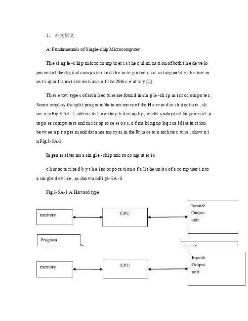
1、外文原文A: Fundamentals of Single-chip MicrocomputerTh e si ng le -c hi p m ic ro co mp ut er i s t he c ul mi na ti on of both t h e de ve lo pm en t of the dig it al com pu te r an d th e in te gr at ed c i rc ui t arg ua bl y t h e tow m os t s ig ni f ic an t i nv en ti on s o f t he 20th c e nt ur y [1].Th es e tow type s of arch it ec tu re are foun d in sin g le -ch i p m i cr oc om pu te r. Som e empl oy the spli t prog ra m/da ta me mo ry of the H a rv ar d ar ch it ect u re , sh ow n in Fig.3-5A -1, oth ers fo ll ow the p h il os op hy , wi del y ada pt ed for gen er al -p ur po se com pu te rs and m i cr op ro ce ss o r s, o f ma ki ng no log i ca l di st in ct ion be tw ee n p r og ra m and dat a me mo ry as in the Pr in ce to n arch ite c tu re , show n i n Fig.3-5A-2.In gen er al ter ms a sin gl e -chi p mic ro co mp ut er i sc h ar ac te ri zed b y t he i nc or po ra ti on of a ll t he un it s of a co mp uter i n to a sin gl e d ev i ce , as sho wn inFi g3-5A -3.Fig.3-5A-1 A Harvard typeFig.3-5A-2. A conventional Princeton computerFig3-5A-3. Principal features of a microcomputerRead only memory (ROM.R OM is usua ll y for the pe rm an ent,n o n-vo la ti le stor a ge of an app lic a ti on s pr og ra m .M an ym i cr oc om pu te rs and m are inte nd e d for high -v ol um e ap pl ic at ions a n d he nc e t h e eco n om ic al man uf act u re of th e de vic e s re qu ir es t h at t he cont en t s o f t he prog ra m me m or y be co mm it t ed perm a ne ntly d u ri ng the man ufa c tu re of ch ip s .Cl ea rl y, thi s im pl ie s a r i go ro us app ro ach to ROM cod e deve l op me nt sin ce cha ng es can not b e mad e afte r manu f a c tu re .Th is dev e lo pm en t proc ess may invo lv e e m ul at io n us in g aso ph is ti ca te d de ve lo pm en t sy ste m wit h a h a rd wa re emu la tio n cap ab il it y as w el l as the use o f po we rf ul s o ft wa re too ls.So me man uf act u re rs pro vi de add it io na l RO M opt i on s by i n cl ud in g in their ra n ge dev ic es wit h (or int en de d fo r use wit h u s er pro gr am ma ble me mo ry. Th e sim p le st of th es e is usu al ly d e vi ce whi ch can op er at e in a micro p ro ce ssor mod e by usi ng som e o f the inp ut /outp u t li ne s as an ad dr es s an d da ta b us fora c ce ss in g ex te rna l mem or y. Thi s t y pe of de vi ce can beh av ef u nc ti on al ly as th e sing le chip mi cr oc om pu te r from whi ch it is d e ri ve d al be it wit h re st ri ct ed I/O and a mod if ied ex te rn al c i rc ui t. The use of thes e d ev ic es is com mo n eve n in prod uc ti on c i rc ui ts wher e t he vo lu me does no tj us ti f y t h e d ev el o pm en t c osts o f c us to m o n -ch i p R OM [2];t he re c a n s ti ll bea s ignif i ca nt saving i n I /O and o th er c h ip s com pa re d to a conv en ti on al mi c ro pr oc es sor b a se d ci rc ui t. Mor e ex ac t re pl ace m en t fo r RO M dev i ce s ca n be o b ta in ed in th e fo rm of va ri an ts w it h 'p ig gy -b ack 'E P RO M(Er as ab le pro gr am ma bl e ROM s oc ke ts or dev ic e s with EPROM i n st ea d o f RO M 。

建筑设计外文文献
建筑设计一直是人类历史上的重要领域,它不仅塑造了城市的风貌,也影响着人们的生活方式和情感体验。
本文旨在探讨近期关于建筑设计的外文文献,从不同角度和流派审视这一主题。
文献一:《The Impact of Natural Light in Architectural Design》
这篇文献探讨了自然光在建筑设计中的重要性。
作者指出,自然光可以增强建筑物的视觉吸引力和舒适度,有助于节能并提高居住者的幸福感。
文中详细描述了利用自然光的技术和策略,包括优化窗户位置、使用光管和反射板等。
文献二:《Sustainable Materials in Contemporary Architecture》
这篇文献关注当代建筑中可持续材料的应用。
作者分析了使用可再生资源和降低环境影响的趋势,探讨了各种替代性材料如竹木、再生玻璃等的优缺点。
文中还探讨了设计师在选择材料时需要考虑的伦理和美学问题。
文献三:《The Role of Technology in Modern Architectural Design》
这篇文献讨论了科技在现代建筑设计中的作用。
作者认为,数字化工具如建模软件和虚拟现实技术为建筑师提供了更大的创作自由和效率。
文中列举了一些成功案例,展示了科技与创意的结合如何推动建筑行业的发展。
结语
建筑设计是一个充满创新和挑战的领域,而以上文献正是引领着这一领域的发展方向。
通过对自然光、可持续材料和科技应用的研究,建筑设计者可以更好地借助环境资源、保护地球,并创造出更美好的建筑作品。
希望这些文献能启发更多关于建筑设计的思考和实践。
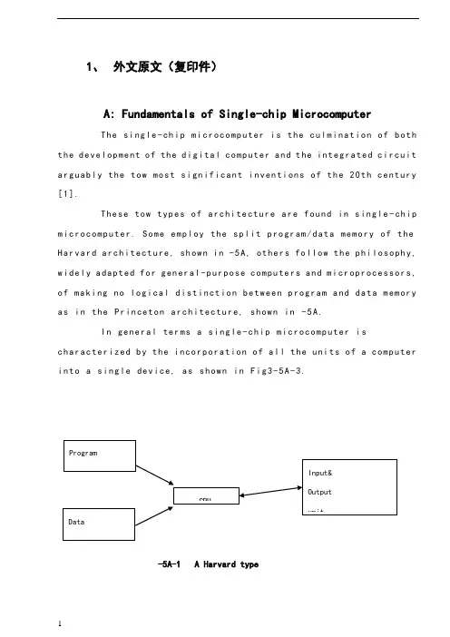
1、外文原文(复印件)A: Fundamentals of Single-chip MicrocomputerTh e si ng le-ch i p mi cr oc om pu ter is t he c ul mi nat i on o f bo th t h e d ev el op me nt o f th e d ig it al com p ut er an d t he int e gr at ed ci rc ui ta r gu ab ly th e t ow m os t s i gn if ic ant i nv en ti on s o f t h e 20t h c en tu ry[1].Th es e to w typ e s of a rc hi te ctu r e ar e fo un d i n s in gl e-ch ip m i cr oc om pu te r. So m e em pl oy t he sp l it p ro gr am/d ata me mo ry o f th e H a rv ar d ar ch it ect u re, sh ow n i n -5A, ot he rs fo ll ow th e ph i lo so ph y, w i de ly a da pt ed fo r g en er al-p ur pos e c om pu te rs an d m i cr op ro ce ss or s, o f m a ki ng no lo gi c al di st in ct io n b e tw ee n p ro gr am a n d da t a m em ory a s i n th e Pr in cet o n ar ch it ec tu re,sh ow n in-5A.In g en er al te r ms a s in gl e-chi p m ic ro co mp ut er i sc h ar ac te ri zed b y the i nc or po ra tio n of al l t he uni t s o f a co mp ut er i n to a s in gl e dev i ce, as s ho wn in Fi g3-5A-3.-5A-1 A Harvard type-5A. A conventional Princeton computerFig3-5A-3. Principal features of a microcomputerRead only memory (ROM).R OM i s u su al ly f or th e p er ma ne nt, n o n-vo la ti le s tor a ge o f an a pp lic a ti on s pr og ra m .M an ym i cr oc om pu te rs an d mi cr oc on tr ol le r s a re in t en de d fo r h ig h-v ol ume a p pl ic at io ns a nd h en ce t he e co nom i ca l ma nu fa ct ure of t he d ev ic es r e qu ir es t ha t the co nt en ts o f the pr og ra m me mo ry b e co mm it te dp e rm an en tl y d ur in g th e m an uf ac tu re o f c hi ps . Cl ear l y, th is im pl ie sa ri g or ou s a pp roa c h t o R OM co de d e ve lo pm en t s in ce c ha ng es ca nn otb e m ad e af te r man u fa ct ur e .T hi s d e ve lo pm en t pr oce s s ma y in vo lv e e m ul at io n us in g a s op hi st ic at ed deve lo pm en t sy st em w i th a ha rd wa re e m ul at io n ca pa bil i ty a s we ll a s th e u se of po we rf ul so ft wa re t oo ls.So me m an uf act u re rs p ro vi de ad d it io na l RO M opt i on s byi n cl ud in g i n th ei r ra ng e de vi ce s wi th (or i nt en de d fo r us e wi th) u s er pr og ra mm ab le m em or y. Th e s im p le st of th es e i s us ua ll y d ev ice w h ic h ca n op er ate in a m ic ro pr oce s so r mo de b y usi n g so me o f th e i n pu t/ou tp ut li ne s as a n ad dr es s an d da ta b us f or acc e ss in g e xt er na l m e mo ry. T hi s t ype o f d ev ic e c an b e ha ve fu nc ti on al l y a s t he si ng le c h ip mi cr oc om pu te r fr om wh ic h i t i s de ri ve d a lb eit w it h r es tr ic ted I/O an d a mo di fie d e xt er na l ci rcu i t. T he u se o f t h es e RO Ml es sd e vi ce s is c om mo n e ve n in p ro du ct io n c ir cu it s wh er e t he v ol um e do es n o t ju st if y th e d e ve lo pm en t co sts of c us to m on-ch i p RO M[2];t he re c a n st il l b e a si g ni fi ca nt s a vi ng in I/O a nd ot he r c hi ps co mp ar ed t o a c on ve nt io nal mi cr op ro ce ss or b as ed c ir cu it. M o re e xa ctr e pl ac em en t fo r RO M d ev ic es c an b e o bt ai ne d in t he f o rm o f va ri an ts w i th 'pi gg y-ba ck'EP RO M(Er as ab le p ro gr am ma bl e ROM)s oc ke ts o rd e vi ce s w it h EP ROM i ns te ad o f R OM 。
毕设外文文献+翻译1外文翻译外文原文CHANGING ROLES OF THE CLIENTS、ARCHITECTSAND CONTRACTORS THROUGH BIMAbstract:Purpose –This paper aims to present a general review of the practical implications of building information modelling (BIM) based on literature and case studies. It seeks to address the necessity for applying BIM and re-organising the processes and roles in hospital building projects. This type of project is complex due to complicated functional and technical requirements, decision making involving a large number of stakeholders, and long-term development processes.Design/methodology/approach–Through desk research and referring to the ongoing European research project InPro, the framework for integrated collaboration and the use of BIM are analysed.Findings –One of the main findings is the identification of the main factors for a successful collaboration using BIM, which can be recognised as “POWER”: product information sharing (P),organisational roles synergy (O), work processes coordination (W), environment for teamwork (E), and reference data consolidation (R).Originality/value –This paper contributes to the actual discussion in science and practice on the changing roles and processes that are required to develop and operate sustainable buildings with the support of integrated ICT frameworks and tools. It presents the state-of-the-art of European research projects and some of the first real cases of BIM application inhospital building projects.Keywords:Europe, Hospitals, The Netherlands, Construction works, Response flexibility, Project planningPaper type :General review1. IntroductionHospital building projects, are of key importance, and involve significant investment, and usually take a long-term development period. Hospital building projects are also very complex due to the complicated requirements regarding hygiene, safety, special equipments, and handling of a large amount of data. The building process is very dynamic and comprises iterative phases and intermediate changes. Many actors with shifting agendas, roles and responsibilities are actively involved, such as: the healthcare institutions, national and local governments, project developers, financial institutions, architects, contractors, advisors, facility managers, and equipment manufacturers and suppliers. Such building projects are very much influenced, by the healthcare policy, which changes rapidly in response to the medical, societal and technological developments, and varies greatly between countries (World Health Organization, 2000). In The Netherlands, for example, the way a building project in the healthcare sector is organised is undergoing a major reform due to a fundamental change in the Dutch health policy that was introduced in 2008.The rapidly changing context posts a need for a building with flexibility over its lifecycle. In order to incorporate life-cycle considerations in the building design, construction technique, and facility management strategy, a multidisciplinary collaboration is required. Despite the attempt for establishing integrated collaboration, healthcare building projects still facesserious problems in practice, such as: budget overrun, delay, and sub-optimal quality in terms of flexibility, end-user?s dissatisfaction, and energy inefficiency. It is evident that the lack of communication and coordination between the actors involved in the different phases of a building project is among the most important reasons behind these problems. The communication between different stakeholders becomes critical, as each stakeholder possesses different setof skills. As a result, the processes for extraction, interpretation, and communication of complex design information from drawings and documents are often time-consuming and difficult. Advanced visualisation technologies, like 4D planning have tremendous potential to increase the communication efficiency and interpretation ability of the project team members. However, their use as an effective communication tool is still limited and not fully explored. There are also other barriers in the information transfer and integration, for instance: many existing ICT systems do not support the openness of the data and structure that is prerequisite for an effective collaboration between different building actors or disciplines.Building information modelling (BIM) offers an integrated solution to the previously mentioned problems. Therefore, BIM is increasingly used as an ICT support in complex building projects. An effective multidisciplinary collaboration supported by an optimal use of BIM require changing roles of the clients, architects, and contractors; new contractual relationships; and re-organised collaborative processes. Unfortunately, there are still gaps in the practical knowledge on how to manage the building actors to collaborate effectively in their changing roles, and todevelop and utilise BIM as an optimal ICT support of the collaboration.This paper presents a general review of the practical implications of building information modelling (BIM) based on literature review and case studies. In the next sections, based on literature and recent findings from European research project InPro, the framework for integrated collaboration and the use of BIM are analysed. Subsequently, through the observation of two ongoing pilot projects in The Netherlands, the changing roles of clients, architects, and contractors through BIM application are investigated. In conclusion, the critical success factors as well as the main barriers of a successful integrated collaboration using BIM are identified.2. Changing roles through integrated collaboration and life-cycle design approachesA hospital building project involves various actors, roles, and knowledge domains. In The Netherlands, the changing roles of clients, architects, and contractors in hospital building projects are inevitable due the new healthcare policy. Previously under the Healthcare Institutions Act (WTZi), healthcare institutions were required to obtain both a license and a building permit for new construction projects and major renovations. The permit was issued by the Dutch Ministry of Health. The healthcare institutions were then eligible to receive financial support from the government. Since 2008, new legislation on the management of hospital building projects and real estate has come into force. In this new legislation, a permit for hospital building project under the WTZi is no longer obligatory, nor obtainable (Dutch Ministry of Health, Welfare and Sport, 2008). This change allows more freedom from the state-directed policy, and respectively,allocates more responsibilities to the healthcare organisations to deal with the financing and management of their real estate. The new policy implies that the healthcare institutions are fully responsible to man age and finance their building projects and real estate. The government?s support for the costs of healthcare facilities will no longer be given separately, but will be included in the fee for healthcare services. This means that healthcare institutions must earn back their investment on real estate through their services. This new policy intends to stimulate sustainable innovations in the design, procurement and management of healthcare buildings, which will contribute to effective and efficient primary healthcare services.The new strategy for building projects and real estate management endorses an integrated collaboration approach. In order to assure the sustainability during construction, use, and maintenance, the end-users, facility managers, contractors and specialist contractors need to be involved in the planning and design processes. The implications of the new strategy are reflected in the changing roles of the building actors and in the new procurement method.In the traditional procurement method, the design, and its details, are developed by the architect, and design engineers. Then, the client (the healthcare institution) sends an application to the Ministry of Healthto obtain an approval on the building permit and the financial support from the government. Following this, a contractor is selected through a tender process that emphasises the search for the lowest-price bidder. During the construction period, changes often take place due to constructability problems of the design and new requirements from the client.Because of the high level of technical complexity, and moreover, decision-making complexities, the whole process from initiation until delivery of a hospital building project can take up to ten years time. After the delivery, the healthcare institution is fully in charge of the operation of the facilities. Redesigns and changes also take place in the use phase to cope with new functions and developments in the medical world.The integrated procurement pictures a new contractual relationship between the parties involved in a building project. Instead of a relationship between the client and architect for design, and the client and contractor for construction, in an integrated procurement the client only holds a contractual relationship with the main party that is responsible for both design and construction. The traditional borders between tasks and occupational groups become blurred since architects, consulting firms, contractors, subcontractors, and suppliers all stand on the supply side in the building process while the client on the demand side. Such configuration puts the architect, engineer and contractor in a very different position that influences not only their roles, but also their responsibilities, tasks and communication with the client, the users, the team and other stakeholders.The transition from traditional to integrated procurement method requires a shift of mindset of the parties on both the demand and supply sides. It is essential for the client and contractor to have a fair and open collaboration in which both can optimally use their competencies. The effectiveness of integrated collaboration is also determined by the client?s capacity and strategy to organize innovative tendering procedures.A new challenge emerges in case of positioning an architect in a partnership with the contractor instead of with the client. In case of the architect enters a partnership with the contractor, an important issues is how to ensure the realisation of the architectural values as well as innovative engineering through an efficient construction process. In another case, the architect can stand at the client?s side in a strategic advisory role instead of being the designer. In this case, the architect?s responsibility is translating client?s requirements and wishes into the architectural values to be included in the design specification, and evaluating the contractor?s proposal against this. In any of this new role, the architect holds the responsibilities as stakeholder interest facilitator, custodian of customer value and custodian of design models.The transition from traditional to integrated procurement method also brings consequences in the payment schemes. In the traditional building process, the honorarium for the architect is usually based on a percentage of the project costs; this may simply mean that the more expensive the building is, the higher the honorarium will be. The engineer receives the honorarium based on the complexity of the design and the intensity of the assignment. A highly complex building, which takes a number of redesigns, is usually favourable for the engineers in terms of honorarium. A traditional contractor usually receives the commission based on the tender to construct the building at the lowest price by meeting the minimum specifications given by the client. Extra work due to modifications is charged separately to the client. After the delivery, the contractor is no longer responsible for the long-term use of the building. In the traditional procurement method, all risks are placed with theclient.In integrated procurement method, the payment is based on the achieved building performance; thus, the payment is non-adversarial. Since the architect, engineer and contractor have a wider responsibility on the quality of the design and the building, the payment is linked to a measurement system of the functional and technical performance of the building over a certain period of time. The honorarium becomes an incentive to achieve the optimal quality. If the building actors succeed to deliver a higher added-value thatexceed the minimum client?s requirements, they will receive a bonus in accordance to the client?s extra gain. The level of transparency is also improved. Open book accounting is an excellent instrument provided that the stakeholders agree on the information to be shared and to its level of detail (InPro, 2009).Next to the adoption of integrated procurement method, the new real estate strategy for hospital building projects addresses an innovative product development and life-cycle design approaches. A sustainable business case for the investment and exploitation of hospital buildings relies on dynamic life-cycle management that includes considerations and analysis of the market development over time next to the building life-cycle costs (investment/initial cost, operational cost, and logistic cost). Compared to the conventional life-cycle costing method, the dynamic life-cycle management encompasses a shift from focusing only on minimizing the costs to focusing on maximizing the total benefit that can be gained. One of the determining factors for a successful implementation of dynamic life-cycle management is the sustainable design of the building and building components, which means that the design carriessufficient flexibility to accommodate possible changes in the long term (Prins, 1992).Designing based on the principles of life-cycle management affects the role of the architect, as he needs to be well informed about the usage scenarios and related financial arrangements, the changing social and physical environments, and new technologies. Design needs to integrate people activities and business strategies over time. In this context, the architect is required to align the design strategies with the organisational, local and global policies on finance, business operations, health and safety, environment, etc.The combination of process and product innovation, and the changing roles of the building actors can be accommodated by integrated project delivery or IPD (AIA California Council, 2007). IPD is an approach that integrates people, systems, business structures and practices into a process that collaboratively harnesses the talents and insights of all participants to reduce waste and optimize efficiency through all phases of design, fabrication and construction. IPD principles can be applied to a variety of contractual arrangements. IPD teams will usually include members well beyond the basic triad of client, architect, and contractor. At a minimum, though, an Integrated Project should include a tight collaboration between the client, the architect, and the main contractor ultimately responsible for construction of the project, from the early design until the project handover. The key to a successful IPD is assembling a team that is committed to collaborative processes and is capable of working together effectively. IPD is built on collaboration. As a result, it can only be successful if the participants share and apply common values and goals.3. Changing roles through BIM applicationBuilding information model (BIM) comprises ICT frameworks and tools that can support the integrated collaboration based on life-cycle design approach. BIM is a digital representation of physical and functional characteristics of a facility. As such it serves as a shared knowledge resource for information about a facility forming a reliable basis for decisions during its lifecycle from inception onward (National Institute of Building Sciences NIBS, 2007). BIM facilitates time and place independent collaborative working. A basic premise of BIM is collaboration by different stakeholders at different phases of the life cycle of a facility to insert, extract, update or modify information in the BIM to support and reflect the roles of that stakeholder. BIM in its ultimate form, as a shared digital representation founded on open standards for interoperability, can become a virtual information model to be handed from the design team to the contractor and subcontractors and then to the client.BIM is not the same as the earlier known computer aided design (CAD). BIM goes further than an application to generate digital (2D or 3D) drawings. BIM is an integrated model in which all process and product information is combined, stored, elaborated, and interactively distributed to all relevant building actors. As a central model for all involved actors throughout the project lifecycle, BIM develops andevolves as the project progresses. Using BIM, the proposed design and engineering solutions can be measured against the client?s requirements and expected building performance. The functionalities of BIM to support the design process extend to multidimensional (nD), including: three-dimensional visualisation and detailing, clash detection, material schedule, planning, costestimate, production and logistic information, and as-built documents. During the construction process, BIM can support the communication between the building site, the factory and the design office– which is crucial for an effective and efficient prefabrication and assembly processes as well as to prevent or solve problems related to unforeseen errors or modifications. When the building is in use, BIM can be used in combination with the intelligent building systems to provide and maintain up-to-date information of the building performance, including the life-cycle cost.To unleash the full potential of more efficient information exchange in the AEC/FM industry in collaborative working using BIM, both high quality open international standards and high quality implementations of these standards must be in place. The IFC open standard is generally agreed to be of high quality and is widely implemented in software. Unfortunately, the certification process allows poor quality implementations to be certified and essentially renders the certified software useless for any practical usage with IFC. IFC compliant BIM is actually used less than manual drafting for architects and contractors, and show about the same usage for engineers. A recent survey shows that CAD (as a closed-system) is still the major form of technique used in design work (over 60 per cent) while BIM is used in around 20 percent of projects for architects and in around 10 per cent of projects for engineers and contractors.The application of BIM to support an optimal cross-disciplinary and cross-phase collaboration opens a new dimension in the roles and relationships between the building actors. Several most relevant issues are: the new role of a model manager; the agreement on the access right and IntellectualProperty Right (IPR); the liability and payment arrangement according to the type of contract and in relation to the integrated procurement; and the use of open international standards.Collaborative working using BIM demands a new expert role of a model manager who possesses ICT as well as construction process know-how (InPro, 2009). The model manager deals with the system as well as with the actors. He provides and maintains technological solutions required for BIM functionalities, manages the information flow, and improves the ICT skills of the stakeholders. The model manager does not take decisions on design and engineering solutions, nor the organisational processes, but his roles in the chain of decision making are focused on:the development of BIM, the definition of the structure and detail level of the model, and the deployment of relevant BIM tools, such as for models checking, merging, and clash detections;the contribution to collaboration methods, especially decision making and communication protocols, task planning, and risk management;and the management of information, in terms of data flow and storage, identification of communication errors, and decision or process (re-)tracking.Regarding the legal and organisational issues, one of the actual questions is: “In what way does the intellectual property right (IPR) in collaborative working using BIM differ from the IPR in a traditional teamwork?”. In terms of combine d work, the IPR of each element is at tached to its creator. Although it seems to be a fully integrated design, BIM actually resulted from a combination of works/elements; for instance: the outline of the building design, is created by the architect, the design for theelectrical system, is created by the electrical contractor, etc. Thus, in case of BIM as a combined work, the IPR is similar to traditional teamwork. Working with BIM with authorship registration functionalities may actually make it easier to keep track of the IPR.How does collaborative working, using BIM, effect the contractual relationship? On the one hand,collaborative working using BIM does not necessarily change the liability position in the contract nor does it obligate an alliance contract. The General Principles of BIM A ddendum confirms: …This does not effectuate or require a restructuring of contractual relationships or shifting of risks between or among the Project Participants other than as specifically required per the Protocol Addendum and its Attachments? (ConsensusDOCS, 2008). On the other hand, changes in terms of payment schemes can be anticipated. Collaborative processes using BIM will lead to the shifting of activities from to the early design phase. Much, if not all, activities in the detailed engineering and specification phase will be done in the earlier phases. It means that significant payment for the engineering phase, which may count up to 40 per cent of the design cost, can no longer be expected. As engineering work is done concurrently with the design, a new proportion of the payment in the early design phase is necessary.4. Review of ongoing hospital building projects using BIMIn The Netherlands, the changing roles in hospital building projects are part of the strategy, which aims at achieving a sustainable real estate in response to the changing healthcare policy. Referring to literature and previous research, the main factors that influence the success of the changing roles can be concluded as: the implementation of an integrated procurementmethod and a life-cycle design approach for a sustainable collaborative process; the agreement on the BIM structure and the intellectual rights; and the integration of the role of a model manager. The preceding sections have discussed the conceptual thinking on how to deal with these factors effectively. This current section observes two actual projects and compares the actual practice with the conceptual view respectively.The main issues, which are observed in the case studies, are: the selected procurement method and the roles of the involved parties within this method;the implementation of the life-cycle design approach;the type, structure, and functionalities of BIM used in the project;the openness in data sharing and transfer of the model, and the intended use of BIM in the future; and the roles and tasks of the model manager.The pilot experience of hospital building projects using BIM in the Netherlands can be observed at University Medical Centre St Radboud (further referred as UMC) and Maxima Medical Centre (further referred as MMC). At UMC, the new building project for the Faculty of Dentistry in the city of Nijmegen has been dedicated as a BIM pilot project. At MMC, BIM is used in designing new buildings for Medical Simulation and Mother-and-Child Centre in the city of Veldhoven.The first case is a project at the University Medical Centre (UMC) St Radboud. UMC is more than just a hospital. UMC combines medical services, education and research. More than 8500 staff and 3000 students work at UMC. As a part of the innovative real estate strategy, UMC has considered to use BIM for its building projects. The new development of the Faculty ofDentistry and the surrounding buildings on the Kapittelweg in Nijmegen has been chosen as a pilot project to gather practical knowledge and experience on collaborative processes with BIM support.The main ambition to be achieved through the use of BIM in the building projects at UMC can be summarised as follows: using 3D visualisation to enhance the coordination and communication among the building actors, and the user participation in design;integrating the architectural design with structural analysis, energy analysis, cost estimation, and planning;interactively evaluating the design solutions against the programme of requirements and specifications;reducing redesign/remake costs through clash detection during the design process; andoptimising the management of the facility through the registration of medical installations andequipments, fixed and flexible furniture, product and output specifications, and operational data.The second case is a project at the Maxima Medical Centre (MMC). MMC is a large hospital resulted from a merger between the Diaconessenhuis in Eindhoven and St Joseph Hospital in Veldhoven. Annually the 3,400 staff of MMC provides medical services to more than 450,000 visitors and patients. A large-scaled extension project of the hospital in Veldhoven is a part of its real estate strategy. A medical simulation centre and a women-and-children medical centre are among the most important new facilities within this extension project. The design has been developed using 3D modelling with several functionalities of BIM.The findings from both cases and the analysis are as follows.Both UMC and MMC opted for a traditional procurement method in which the client directly contracted an architect, a structural engineer, and a mechanical, electrical and plumbing (MEP) consultant in the design team. Once the design and detailed specifications are finished, a tender procedure will follow to select a contractor. Despite the choice for this traditional method, many attempts have been made for a closer and more effective multidisciplinary collaboration. UMC dedicated a relatively long preparation phase with the architect, structural engineer and MEP consultant before the design commenced. This preparation phase was aimed at creating a common vision on the optimal way for collaboration using BIM as an ICT support. Some results of this preparation phase are: a document that defines the common ambition for the project and the collaborative working process and a semi-formal agreement that states the commitment of the building actors for collaboration. Other than UMC, MMC selected an architecture firm with an in-house engineering department. Thus, the collaboration between the architect and structural engineer can take place within the same firm using the same software application.Regarding the life-cycle design approach, the main attention is given on life-cycle costs, maintenance needs, and facility management. Using BIM, both hospitals intend to get a much better insight in these aspects over the life-cycle period. The life-cycle sustainability criteria are included in the assignments for the design teams. Multidisciplinary designers and engineers are asked to collaborate more closely and to interact with the end-users to address life-cycle requirements. However, ensuring the building actors to engage in an integrated collaboration to generate sustainable design solutions that meet the life-cycle。

西南交通大学本科毕业设计外文翻译年级:学号:姓名:专业:指导老师xx 年xx、月院系 xxx 专业电气工程及其自动化年级 xx 姓名 xxx题目外文翻译指导教师评语指导教师 (签章)评阅人评语评阅人 (签章) 成绩答辩委员会主任 (签章)年月日目录ABSTRACT (1)I. INTRODUCTION (1)II. DESIGN OF HARDWARE FOR TEMPERATURE CONTROL SYSTEM (2)III. DESIGN OF SIGNAL WIRELESS TRANSMISSION (3)IV. SOFTWARE DESIGN (4)V. CONCLUSION (11)REFERENCES (12)摘要 (13)I 介绍 (13)II 对温度控制系统的硬件是合计 (13)III 设计信号的无线传输 (14)IV 软件设计 (15)V 结论 (19)Design of Temperature Control Device Underground Coal Mine Based on AT89S52ABSTRACTAbstract-Temperature underground coal mine is an important index, especially for mining workers underground. To monitor the temperature effectively, a temperature measurement and control system is necessary to design. Temperature value is displayed on LED screen on line. When temperature value reaches the maximum, conditioning device connected with the opening end of the relay controlled by the MeV will start up. Temperature signal and control information is all transmitted by wireless signal transmission module nRF905. The system program consists of transducer control and display of the temperature value. The control program of transducer is compiled according to its communication protocol. Program of wireless data transmission should be debugged between the data transmission modules. Alarm device is designed to provides effective information to workers when the temperature value is unusual. Thus monitoring of the temperature underground coal mine can be real and effective.Keywords: Index Terms-DS18B20, AT89S52, nRF905, coal mine temperature controlI. INTRODUCTIONThe environment underground coal mine is poor, and various dangers can easily occur. Therefore, in order to ensure safe production of coal mine, it is needed to supervise various parameters underground coal mine, including temperature, pressure, gas, wind speed and distance. Timely monitoring temperatures of some mine key points and coal face is an important monitoring project to guaranteesafe production. Moreover, the ultrasonic measurement of distance is usually used in coal mine, to ensure the accuracy of measurement, it is also needed to make accurate temperature measurement. Traditional temperature measurement is done by classical isolated sensors, which has some disadvantages as follows: slow reaction rate, high measuring errors, complex installation and debugging and inconvenient long-distance transmission. In this paper intelligent temperature measurement and control is realized by taking DS18B20 temperature sensor and AT89S52 MCU as platform. DS18B20 has some advantages, mainly including digital counting, direct output of the measured temperature value in digital form, less temperature error, high resolution, strong anti-interference ability, long-distance transmission and characteristic of serial bus interface. Comparing with the traditional method of temperature measurement, MCU temperature measurement can achieve storage and analysis of temperature data, remote transmission and so on. DS18B20 sensor is a series of digital single bustemperature sensor made in DALLAS company ofUSA.[I]II. DESIGN OF HARDWARE FOR TEMPERATURE CONTROL SYSTEM The device is composed of the temperature sensor DS18B20, MCU AT89S52, display module and relay for main fan control. The principle diagram of this hardware is shown in Fig.l.DS18B20 temperature sensor converts the environmental temperature into signed digital signal (with 16 bits complementary code accounting for two bytes), its output pin 2 directly connected with MCU Pl.2. Rl is pull-up resistor and the sensor uses external power supply. Pl.7 is linked to relay and PO is linked to LED display. AT89S52 is the control core of the entire device. Display modules consists of quaternity common-anode LED and four 9012. The read-write of sensor, the display of temperature and the control of relay are completed by program control ofthe system. [2]III. DESIGN OF SIGNAL WIRELESS TRANSMISSIONTested signal is transmitted by wireless mode, as shown in Fig. 1. Wire transmitting of signal underground coal mine has some disadvantages:1) The mineral products are mined by excavation of shaft and tunnel. Meanwhile, there are so many equipments used underground coal mine. Therefore, it is more difficult to wiring in shaft and tunnel, and environmental suitability is poor for wire transmitting of signals;2) Support workers should check up cables for transmitting signals at any moment when combined motion of the coal machine support occurs. Thus, workers' labor intensity is increased;3) The long-distance transmission of sensing element with contact method may lead to larger errors. To reduce errors, the long-distance line driver and safety barrier are needed. Thus, the cost is increased;4) The work load of maintenance underground coal mine is larger.Figure 1. Structure diagram of signal wireless transmission systemBy contrast, adopting wireless data transmission can effectively avoid theabove disadvantages. [3]Wireless signal transmission module nRF905 is used in the design. Its characteristics are as follows: Integrated wireless transceiver chip nRF905 works in the ISM band 433/868/915 MHz, consists of a fully integrated frequency modulator, a receiver with demodulator, a power amplifier, a crystal oscillator and a regulator. Its working mode of operation is Shock Burst. Preambles and CRC code are automatically generated in the mode, and can easily be programmed through the SPI interface. Current consumption of the module is very low. When the transmit power is +10 dBm, the emission current is 30 rnA and receiving current is 12.2 rnA. It also can enter POWERDOWN model to achieve energy-saving. [4]IV. SOFTWARE DESIGNFor doing the read-write programming for DS18B20, its read-write time sequence should be guaranteed. Otherwise, the result oftemperature measurement will not be read.Figure 2. Software design flow chartTherefore, program design for operation on DS18B20 had better adopt assembly language.[5] Software design flow chart is shown in Fig.2.Structure of Main program for temperature measurement is shown as following: INIT 1820:SETB DINNOPCLRDINMOV RO,#250TSRI: DJNZ RO,TSRINOPNOPNOPMOV RO,#60TSR2: DJNZ RO,TSR2 JNB PI.0,TSR3 LJMPTSR4TSR3: SETB FLAGI LJMPTSR5TSR4: CLR FLAG1 LJMPTSR7TSR5: MOY RO,#6BH TSR6: DJNZ RO,TSR6 TSR7: SETB DIN SETB DINRETGET TEMPER:SETB DINLCALL INIT 182018 FLAG1,TSS2RETTSS2: MOY A,#OCCH LCALL WRITE 1820 MOY A,#44HLCALL WRITE 1820 LCALL DELAYLCALL DELAY LCALLDELAYLCALL DELAY LCALLDELAY LCALL INIT 1820 MOY A,#OCCH LCALL WRITE 1820 MOY A,#OBEH LCALL WRITE 1820 LCALL READ 1820 RETWRITE 1820: MOY R2,#8CLRCREAD_l 820: MOVR4,#2MOV Rl,#29H REOO: MOV R2,#8 REOl: CLR C SETB DINNOPNOPCLRDINNOPNOPNOPSETB DINMOVR3,#9 ADJUST_TEMPER: CLR TEM_BITJNB 47H,AJUST SETB TEM_BITXRL TEMPER_L,#OFFH MOV A,TEMPER_L ADDA,#OlHMOV TEMPE~L,AXRL TEMPER_H,#OFFH MOV A,TEMPER_H ADDCA,#OOHMOV TEMPER_H,A ADJUST:MOV A,TEMPER_L MOV B,#lOODIVABMOV B_BIT,AMOV A,BMOV B,#lODIVABMOV S_BIT,AMOV G_BIT,BDISP MAIN:LCALL D_DISP LCALL G_DISP LCALL S_DISP LCALL B_DISPMOV A,#OFFH LCALLDISPMOV A,#OFFHLCALL DISPMOV A,#OFFH LCALLDISP MOV A,#OFFH LCALL DISP LCALLDELAY RETD DISP: MOVC,D_BITJC D DISPI MOV A,#03H LCALL DISP RETD DISPl:MOV A,#49H LCALL DISP RETG DISP:MOV A,G_BIT MOV DPTR,#TAB MOVC A,@A+DPTR ANLA,#OFEH LCALL DISP RETS DISP:MOV A,S_BIT MOV DPTR,#TAB MOVC A,@A+DPTR LCALL DISP RETB DISP:JNB TEM_BIT,B_DISMOV A,#OfdhLCALL DISPRETB DIS:JB l8H,B_lMOV A,#OffhLCALL DISPRETB 1: MOV A,#03HLCALL DISPRETDISP: CLRCMOVR2,#8DIS: RRCAMOVDAT,CCLRCLKSETBCLKCLRCLKDJNZ R2,DISRETDELAY: MOV R3,#80hDl: MOV R4,#OfEhDJNZ R4,$DJNZ R3,DlRETTAB:DB 03H,9FH,25H,ODH,99H DB 49H,4IH,IFH,OIH,09HENDV. CONCLUSIONThe performance of measurement-control device mainly depends on the performance of sensing element, the processing circuit and the transmission efficiency of collected data. Digital temperature sensor DSl8B20 and processing chip AT89S52 have characteristics of good technical indexes, and the field operations indicate that circuits system has many advantages, such as accurate data detection, good stability and easy adjustment.After industrial operation test, the system is excellent for worst mine environment, which provides powerful assurance for safe production in the coal industry, and brings good economic and social benefits.REFERENCES[1] WANG Furui, "Single chip microcomputer measurement and control system comprehensive design," Beijing University of Aeronautics and Astronautics Press, 1998.[2] XIA Huguo, "Technology application in automation combined-mining face," Shaanxi Coal, 2007.[3] SHA Zhanyou, "Principle and application of intelligent integrated temperature sensor," Mechanical Industry Publishing House, 2002.[4] CAO Shujuan, HE Yinyong, GUO San-rning, On-line temperaturemeasuring system involving coal mine, Journal of Heilongjiang Instituteof Science & Technology,7(2005)[5] SUN Xiaoqing, XIAO Xingming, WANG Peng, "Design of MeasuringSystem for Rotating Speed of Hoist Based on Virtual Instrument," Coal Mine Machinery, 12(2005).基于AT89S52煤矿井下的温度控制装置的设计摘要煤矿井下抽象温度是评价学术期刊的重要指标,特别是对在地下工作的采矿工。

中英文对照外文翻译文献(文档含英文原文和中文翻译)原文:Housing Problems and Options for the Elderly 1. IntroductionHousing is a critical element in the lives of older persons. The affordability of housing affects the ability of the elderly to afford other necessities of life such as food and medical care. Housing that is located near hospitals and doctors, shopping, transportation, and recreational facilities can facilitate access to services that can enhance the quality of life. Housing can also be a place of memories of the past and a connection to friends and neighbors. Housing with supportive features and access to services can also make it possible for persons to age in place. In this session, we will be examining housing problems andoptions for the elderly. Along the way, we will be testing your housing IQ with a series of questions and exercises.2. Housing Situation of Older PersonsHow typical is the housing situation of the olders?We will begin by examining five areas :(1)Prevalence of home ownership (2)Length of stay in current residence (3)Living arrangements (4)Attachments of older persons to where they live (5)Moving behavior.With whom older persons live can influence housing affordability, space needs, and the ability to age in place. About 54% of older persons live with their spouses, 31% live alone, almost 13% live with related persons other than their spouse and about 2% live with unrelated persons. With increasing age, older persons (primarily women) are more likely to live alone or with a relative other than a spouse. Frail older women living alone are the persons most likely to reside in homes with ‘extra’ rooms and to need both physically supportive housing features and services to "age in place". This segment of the population is also the group most likely to move to more supportive housing settings such as assisted living.Many older persons have strong psychological attachments to their homes related to length of residence. The home often represents the place where they raised their children and a lifetime of memories. It is also a connection to an array of familiar persons such as neighbors and shopkeepers as well as near by places including houses of worship, libraries and community services. For manyolder persons, the home is an extension of their own personalities which is found in the furnishings . In addition, the home can represent a sense of economic security for the future, especially for homeowners who have paid off their mortgages. For owners, the home is usually their most valuable financial asset. The home also symbolizes a sense of independence in that the resident is able to live on his or her own. For these types of reasons, it is understandable that in response to a question about housing preferences, AARP surveys of older persons continue to find that approximately 80% of older persons report that what they want is to "stay in their own homes and never move." This phenomena has been termed the preference to "age in place."Although most older persons move near their current communities, some seek retirement communities in places with warmer weather in the southwest, far west and the south.3. The Federal Government's Housing Programs for the ElderlyThe federal government has had two basic housing strategies to address housing problems of the elderly. One strategy, termed the "supply side" approach, seeks to build new housing complexes such as public housing and Section 202 housing for older persons. Public housing is administered by quasi-governmental local public housing authorities. Section 202 Housing for the elderly and disabled is sponsored by non-profit organizations including religious and non-sectarian organizations. Approximately 1.5 million olderpersons or 3% of the elderly population live in federally assisted housing, with about 387,000 living in Section 202 housing. Over time, the government has shifted away from such new construction programs because of the cost of such housing, the problems that a number of non-elderly housing programs have experienced, and a philosophy that the government should no longer be directly involved with the building of housing. Section 202 housing, a very popular and successful program, is one of the few supply-side programs funded by the federal government, although the budget allocation during the last ten years has allowed for the construction of only about 6,000 units per year compared to a high of almost 20,000 units in the late 1970s. Instead of funding new construction, federal housing initiatives over the last decade have emphasized ‘demand side’ subsidies that provide low-income renters with a certificate or a voucher that they can use in a variety of multiunit settings, including apartments in the private sector that meet rental and condition guidelines. These vouchers and certificates are aimed at reducing excessive housing costs. Some certificates are termed ‘project based’ subsidies and are tied to federally subsidized housing such as Section 202. Because housing programs are not an entitlement, however, supply-side and demand side programs together are only able to meet the needs of about 1/3 of elderly renters who qualify on the basis of income.While advocates for housing have been trying to hold on to the existing programs in the face of huge budget cuts at HUD, much of the attention has been shifting towards meeting the shelter and service needs of the frail elderly. This emphasis reflects the increasing number of older persons in their eightiesand nineties who need a physically supportive environment linked with services. This group of older persons includes a high percentage of older residents of public and Section 202 housing. Initially built for independent older persons who were initially in the late sixties and early seventies, this type of housing now includes older persons in their eighties and nineties, many of whom have aged in place. Consequently, the government is faced with creating strategies to bring services into these buildings and retrofit them to better suit the needs of frail older persons. A major initiative of the early 1990s, which may be stalled by current budget problems at HUD, has been for the federal government to pay for service coordinators to assess the needs of residents of government assisted housing complexes and link them with services. As of 1998, there were approximately 1,000 service coordinators attached to government assisted housing complexes across the country.4. The Housing Continuum: A Range of Options for ElderlyA long-standing assumption in the field of housing has been that as persons become more frail, they will have to move along a housing continuum from one setting to another. As the figure on housing options suggests, along this continuum are found a range of housing options including single family homes, apartments, congregate living, assisted living, and board and care homes (Kendig & Pynoos, 1996). The end point of the housing continuum has been thenursing home. These options vary considerably in terms of their availability, affordability, and ability to meet the needs of very frail older persons.The concept of a continuum of supportive care is based on the assumption that housing options can be differentiated by the amount and types of services offered; the supportiveness of the physical setting in terms of accessibility, features, and design; and the competency level of the persons to whom the housing is targeted. The figure on housing options indicates how such options generally meet the needs of older persons who are categorized,as independent, semi-dependent and dependent. Semi-dependent older persons can be thought of as needing some assistance from other persons with instrumental activities of daily living (IADLs) such as cooking, cleaning, and shopping. In addition to needing assistance with some IADLs, dependent older persons may require assistance with more basic activities such as toileting, eating and bathing. Although semi-dependent and dependent older persons can be found throughout the housing continuum, independent older persons are very unlikely to reside in housing types such as assisted living specifically designed and equipped to meet the needs of frail older persons unless their spouses require these needs.Although the continuum of housing identifies a range of housing types, there is increasing recognition that frail older persons do not necessarily have to move from one setting to another if they need assistance. Semi-dependent or dependent older persons can live in a variety of settings, including their own homes and apartments, if the physical environment is made more supportive, caregivers are available to provide assistance and affordable services areaccessible.5. ConclusionsHousing plays a critical role in the lives of older persons. Most older homeowners who function independently express a high level of satisfaction with their dwelling units. However, high housing costs, especially for renters, remain a financial burden for many older persons and problems associated with housing condition persist especially for low- income renters and persons living in rural areas. Federal housing programs such as public housing, Section 202 housing, and Section 8 housing certificates have only been able to address the basic housing problems of only about one-third of eligible older persons because of limited budgets. Moreover, a shortage of viable residential options exists for frail older persons. Up until the last decade, housing for the elderly was conceived of primarily as shelter. It has become increasingly recognized that frail older persons who needed services and physically supportive features often had to move from their homes or apartments to settings such as board and care or nursing homes to receive assistance. Over time, however, the concept of a variety of housing types that can be linked has replaced the original idea of the continuum of housing. It is possible for frail older persons to live in a variety of existing residential settings, including their own homes and apartments with the addition of services and home modifications. Consequently, the last decade has seen a number of efforts to modify homes, add service coordinators to multi-unit housing and create options such as accessory and ECHO units. Although thesestrategies have been enhanced by a somewhat greater availability of home care services, Medicaid policy still provides incentives to house frail older persons in nursing homes. The most visible development in the field of housing for frail older persons has been the growth of private sector assisted living which is now viewed by many state governments as a residential alternative to nursing homes. The AL movement itself has raised a number of regulatory and financing issues that cross-cut housing and long term care such as what constitutes a residential environment, insuring that residents can age in place, accommodating resident preferences, protecting the rights of individuals and insuring quality of care. Nevertheless, the emergence of AL along with a wider range of other housing options holds out the promise that older persons will have a larger range of choices among living arrangements.译文:老年人的住宅问题与选择一、简介住宅在老年人生活的极为重要。

毕业设计英文文献翻译(电力方向附带中文)大学毕业设计英文文献翻译,关于电力系统方向,电力谐波!绝对原创!HarmonicsService reliability and quality of power have become growing concerns for many facility managers, especially with the increasing sensitivity of electronic equipment and automated controls. There are several types of voltage fluctuations that can cause problems, including surges and spikes, sags, harmonic distortion, and momentary disruptions. Harmonics can cause sensitive equipment to malfunction and other problems, including overheating of transformers and wiring, nuisance breaker trips, and reduced power factor.What Are Harmonics?Harmonics are voltage and current frequencies riding on top of the normal sinusoidal voltage and current waveforms. Usually these harmonic frequencies are in multiples of the fundamental frequency, which is 60 hertz (Hz) in the US and Canada. The mostcommon source of harmonic distortion is electronic equipment using switch-mode power supplies, such as computers, adjustable-speed drives, and high-efficiency electronic light ballasts.Harmonics are created by these Dswitching loads‖ (also called “nonlinear loads,‖ because current does not vary smoothly with voltage as it does with simple resistive and reactive loads): Each time the current is switched on and off, a current pulse is created. The resulting pulsed waveform is made up of a spectrum of harmonic frequencies, including the 60 Hz fundamental and multiples of it. This voltage distortion typically results from distortion in the current reacting with system impedance. (Impedance is a measure of the total opposi tion―resistance, capacitance, and inductance―to the flow of an alternating current.) The higher-frequency waveforms, collectively referred to as total harmonic distortion (THD), perform no useful work and can be asignificant nuisance.Harmonic waveforms are characterized by their amplitude and harmonic number. In the U.S. and Canada, the third harmonic is 180 Hz―or 3 x 60 Hz―and the fifth harmonic is 300 Hz (5 x 60Hz). The third harmonic (and multiples of it) is the largest problem in circuits with single-phase loads such as computers and fax machines. Figure 1 shows how the 60-Hz alternating current (AC) voltage waveform changes when harmonics are added.大学毕业设计英文文献翻译,关于电力系统方向,电力谐波!绝对原创!The Problem with HarmonicsAny distribution circuit serving modern electronic devices will contain some degree of harmonic frequencies. The harmonics do not always cause problems, but the greater the power drawn by these modern devices or other nonlinear loads, the greater the level of voltage distortion. Potential problems (or symptoms of problems) attributed to harmonics include:■ Malfunction of sensitive equipment■ Random tripping of circuit breakers■ Flickering lights■ Very high neutral currents■ Overheated phase conductors, panels, and transformers ■ Premature failure of transformers and uninterruptible power supplies (UPSs)■ Reduced power factor■ Reduced system capacity (because harmonics create additional heat, transformers and otherdistribution equipment cannot carry full rated load)Identifying the ProblemWithout obvious symptoms such as nuisance breaker trips or overheated transformers, how do you determine whether harmonic current or voltages are a cause for concern? Here are several suggestions for simple, inexpensive measurements that a facility manager or staff electrician could take, starting at the outlet and moving upstream:■ Measure the peak and root mean square (RMS) voltage at a sample of receptacles. The Dcrest factor‖ is the ra tio of peak to RMS voltage. For a perfectly sinusoidal voltage, the crest factor will be 1.4. Low crest factor is a clear indicator of the presence of harmonics. Note that these measurements must be performed with a Dtrue RMS‖ meter―one that doesn‘t assume a perfectly sinusoidal waveform.■ Inspect distribution panels. Remove panel covers and visually inspect components for signs of overheating, including discolored or receded insulation or discoloration of terminal screws. If you see any of these symptoms, check that connectionsare tight (since loose connections could also cause overheating), and compare currents in all conductors to their ratings.■ Measure phase and neutral currents at the transformer secondary with clamp-on current probes. If no harmonics are being generated, the neutral current of a three-phase distribution system carries only the imbalance of the phase currents. In a well-balanced three-phase distribution system, phase currents will be very similar, and current in the neutral conductor should be much lower than phase current and far below its rated current capacity. If phase currents are similar and neutral current exceeds their imbalance by a wide margin, harmonics are present. If neutral current is above 70 percent of the cond uctor‘s rated capacity, you need to mitigate the problem.■Compare transformer temperature and loading with nameplate temperature rise and capacity ratings. Even lightly loaded transformers can overheat if harmonic current is high. A transformer that is near or over its rated temperature rise but is loaded well below its rated capacity is a clear sign that harmonics are at work. (Many transformers have built-in temperature gauges. If yours does not, infrared thermography can be used to detect overheating.)大学毕业设计英文文献翻译,关于电力系统方向,电力谐波!绝对原创!In addition to these simple measurements, many power-monitoring devices are now commercially available from a variety of manufacturers to measure and record harmonic levels. These instruments provide detailed information on THD, as well as on the intensity of individual harmonic frequencies. After taking the appropriate measurements to determine whether you have high levels of harmonics and, if so, to find the source, you will be well-positioned to choose the best solution.Solutions to Harmonics ProblemsThe best way to deal with harmonics problems is through prevention: choosing equipment and installation practices that minimize the level of harmonics in any one circuit or portion of a facility. Many power quality problems, including those resulting from harmonics, occur when new equipment is haphazardly added to older systems. However, even within existing facilities, the problems can often be solved with simple solutions such as fixing poor or nonexistent grounding on individual equipment or the facility as a whole, moving a few loads between branch circuits, or adding additional circuits to help isolate the sensitiveequipment from what is causing the harmonic distortion. If the problems cannot be solved by these simple measures, there are two basic choices: to reinforce the distribution system to withstand the harmonics or to install devices to attenuate or remove the harmonics. Reinforcing the distribution system means installing double-size neutral wires or installing separate neutral wires for each phase, and/or installing oversized or Krated transformers, which allow for more heat dissipation. There are also harmonic-rated circuit breakers and panels, which are designed to prevent overheating due to harmonics. This option is generally more suited to new facilities, because the costs of retrofitting an existing facility in this way could be significant. Strategies for attenuating harmonics, from cheap to more expensive, include passive harmonic filters, isolation transformers, harmonic mitigating transformers (HMTs), the Harmonic Suppression System (HSS) from Harmonics Ltd., and active filters(Table 1).Passive filters (also called traps) include devices that provide low-impedance paths to divert harmonics to ground and devices that create a higher-impedance path to discourage the flow of harmonics. Both of these devices, by necessity, change theimpedance characteristics of the circuits into which they are inserted. Another weakness of passive harmonic technologies is that, as their name implies, they cannot adapt to changes in the electrical systems in which they operate. This means that changes to the electrical system (for example, the addition or removal of power factorCcorrection capacitors or the addition of more nonlinear loads) could cause them to be overloaded or to create Dresonances‖ that could actually amplify, rather than diminish, harmonics.Active harmonic filters, in contrast, continuously adjust their behavior in response to the harmonic current content of the monitored circuit, and they will not cause resonance. Like an automatic transmission in a car, active filters are designed to accommodate a full range of expected operating conditions upon installation, without requiring further adjustments by the operator.Isolation transformers are filtering devices that segregate harmonics in the circuit in which they are created, protecting upstream equipment from the effects of harmonics. These transformers do not remove the problem in the circuit generating the harmonics, but they can prevent the harmonics from affecting more sensitive equipment elsewhere within the facility.大学毕业设计英文文献翻译,关于电力系统方向,电力谐波!绝对原创!Harmonic mitigating transformers actually do relieve problematic harmonics. HMTs can be quite cost-effective in the right application, because they can both improve reliability and reduce energy costs. The right application includes transformers that are heavily or moderately loaded and where high levels of harmonic currents are present. In addition, HMTs are very effective in supporting critical loads that are backed up by a UPS. UPSs and backup generators tend to have high impedance, which results in high voltage distortion under nonlinear loading. Because of this, equipment that operates flawlessly when supplied by utility power may malfunction when the backup system engages during a utility outage. Note that some of these power systems have output filters (either passive or active) to control harmonic levels. The presence or absence of such filters should be determined before adding an HMT.The Harmonics Ltd. Harmonic Suppression System is a unique solution for single-phase loads that is designed to suppress the third harmonic. An HSS is generally more expensive than an HMT, but it is designed to attenuate the harmonicsproblems throughout the entire distribution system, not just upstream of the transformer. The types of facilities that present the best opportunities for HSS installation are those that place a very high premium on power quality and reliability, such as server farms, radio and television broadcast studios, and hospitals. (See .) Economic EvaluationEvaluating the life-cycle costs and effectiveness of harmonics mitigation technologies can be ve ry challenging―beyond the expertise of most industrial facility managers. After performing the proper measurement and analysis of the harmonics problem, this type of evaluation requires an analysis of the costs of the harmonics problem (downtime of sensitive equipment, reduced power factor, energy losses or potential energy savings) and the costs of the solutions. A good place to start in performing this type of analysis is to ask your local utility or electricity provider for assistance. Many utilities offer their own power quality mitigation services or can refer you to outside power quality service providers.Additional ResourcesInstitute of Electrical and Electronics Engineers (IEEE),Standard 519-1992, DIEEE大学毕业设计英文文献翻译,关于电力系统方向,电力谐波!绝对原创!Recommended Practices and Requirements for Harmonic Control in Electric Power Systems‖ (1992), available at .Relationship between harmonics and symmetrical componentsAbstract New terminology is introduced to make clear the relationship between harmonics and symmetrical components. Three-phase sets are classified in terms of symmetrical sets and asymmetrical sets. Subclasses are introduced with the names symmetrical balanced sets, symmetrical unbalanced sets, asymmetrical balanced sets and asymmetrical unbalanced sets to show that a threephase set can resolve to either one, two or three symmetrical component sets. The results from four case studies show that these subclasses and their resolution to symmetrical component sets improve understanding of harmonic analysis of systems having balanced and unbalanced harmonic sources and loads.Keywords asymmetrical sets; harmonic flows; harmonic sources; symmetrical component sets; symmetrical sets Any periodic wave shape can be broken down into oranalysed as a fundamentalwave and a series of harmonics.Three-phase harmonic analysis requires a clear understanding of the relationship between symmetrical component injections from harmonic sources (e.g. adjustable speed drives, ASDs) and their relationship to harmonic flows (symmetrical components) arising from the application of a harmonic source to a linear system.Alimited number of references contain brief information concerning harmonics and symmetrical components. Reference 1, provides a paragraph on this topic and uses the heading Relationship between Harmonics and Symmetrical Components‘.It includes a table that is supported by a brief explanatory paragraph. The table expresses harmonics in terms of positive, negative and zero sequences. It states that these sequences are for harmonics in balanced three-phase systems. The heading refers to symmetrical components while the content refers to balanced three-phase systems. Herein lies the anomaly. Classically, symmetrical components (especially ero sequence) are only applied in unbalanced systems. The following questions rose after reading the Ref. 1 paragraph.(a)Do symmetrical components (especially zero sequence), in the classical sense,apply in balanced as well as unbalanced non-sinusoidal systems and is this abreak from tradition?(b)What do the terms, symmetrical, asymmetrical, balanced, unbalanced andsymmetrical components mean?(c)What are the conditions under which a system must operate so that harmonicsresolve to positive, negative and zero sequences and is the table given inRef. 1 correct?The terminology used is found inadequate for describing non-sinusoidal systems.There is thus a need to introduce a three-phase terminology that will show the relationship and make the comparison between injections (currents) and harmonic flows (voltages and currents) meaningful.References 3 provides the basis for the solution by providing definitions for threephase sets‘, symmetrical sets‘an d symmetricalcomponent sets‘.The purpose of this paper is to introduce an approach to harmonic analysis大学毕业设计英文文献翻译,关于电力系统方向,电力谐波!绝对原创!based on the classification of three-phase sets and to make to comparison between injections from harmonic sources and corresponding harmonic flows quantifiable by expressing the results in terms of the number of symmetrical component sets found.Harmonic flows and their resolution to symmetrical components depends upon the magnitudes and phase sequences of the injections from a harmonic source, on the system‘s sequence impedances, on three- and four-wire connections and on whether the customer‘s linear load on the system is balanced or unbalanced. Therefore, what is injected in terms of symmetrical component sets by a harmonic source is not necessarily received by the system, i.e. the harmonic flows may resolve to one, two or three symmetrical component sets and this depends upon the type of three-phase set found. Therefore, any three-phase harmonic may be partially made up of any of thesymmetrical component sets.Four case studies are reported and they show a novel method for teaching the flow of power system harmonics. It is important to use case studies as part of one‘s teaching as they link learning to concepts and improve understanding. They show how the method of symmetrical components can be extended to a system‘s response to harmonic flows. When taught as a group, the four case studies improve cognitive skills by showing that the symmetrical component responses under unbalanced situations are different to the balanced state.IEEE __TIONS ON POWER __NICS VOL.19,NO.3,__年大学毕业设计英文文献翻译,关于电力系统方向,电力谐波!绝对原创!谐波服务的可靠性和电能质量已成为越来越多设施经理的关注,尤其是随着电子设备和自动化控制灵敏度提高了很多。
3-电气工程及其自动化专业外文文献英文文献外文翻译1、外文原文(复印件)A: Fundamentals of Single-chip MicrocomputerThe single-chip microcomputer is the culmination of both the development of the digital computer and the integrated circuit arguably the tow most significant inventions of the 20th century [1].These tow types of architecture are found in single-chip microcomputer. Some employ the split program/data memory of the Harvard architecture, shown in Fig.3-5A-1, others follow the philosophy, widely adapted for general-purpose computers and microprocessors, of making no logical distinction between program and data memory as in the Princeton architecture, shown in Fig.3-5A-2.In general terms a single-chip microcomputer is characterized by the incorporation of all the units of a computer into a single device, as shown in Fig3-5A-3.ProgramInput& memoryOutputCPU unitDatamemoryFig.3-5A-1 A Harvard typeInput&Output CPU memoryunitFig.3-5A-2. A conventional Princeton computerExternal Timer/ System Timing Counter clock componentsSerial I/OReset ROMPrarallelI/OInterrupts RAMCPUPowerFig3-5A-3. Principal features of a microcomputerRead only memory (ROM).ROM is usually for the permanent,non-volatile storage of an applications program .Many microcomputers and microcontrollers are intended for high-volume applications and hence the economical manufacture of the devices requires that the contents of the program memory be committed permanently during the manufacture of chips . Clearly, this implies a rigorous approach to ROM code development since changes cannot be made after manufacture .This development process may involve emulation using a sophisticated development system with a hardware emulation capability as well as the use of powerful software tools.Some manufacturers provide additional ROM options by including in their range devices with (or intended for use with) user programmablememory. The simplest of these is usually device which can operate in a microprocessor mode by using some of the input/output lines as an address and data bus for accessing external memory. This type of device can behave functionally as the single chip microcomputer from which itis derived albeit with restricted I/O and a modified external circuit. The use of these ROMlessdevices is common even in production circuits where the volume does not justify the development costs of custom on-chip ROM[2];there canstill be a significant saving in I/O and other chips compared to a conventional microprocessor based circuit. More exact replacement for ROM devices can be obtained in the form of variants with 'piggy-back' EPROM(Erasable programmable ROM )sockets or devices with EPROM instead of ROM 。
毕业设计英文文献翻译(电力方向附带中文)大学毕业设计英文文献翻译 ,关于电力系统方向,电力谐波!绝对原创!HarmonicsService reliability and quality of power have become growing concerns for many facility managers, especially with the increasing sensitivity of electronic equipment and automated controls. There are several types of voltage fluctuations that can cause problems, including surges and spikes, sags, harmonic distortion, and momentary disruptions. Harmonics can cause sensitive equipment to malfunction and other problems, including overheating of transformers and wiring, nuisance breaker trips, and reduced power factor.What Are Harmonics?Harmonics are voltage and current frequencies riding on top of the normal sinusoidal voltage and current waveforms. Usually these harmonic frequencies are in multiples of the fundamental frequency, which is 60 hertz (Hz) in the US and Canada. The most common source of harmonic distortion is electronic equipment using switch-mode power supplies, such as computers, adjustable-speed drives, and high-efficiency electronic light ballasts.Harmonics are created by these ―switching loads‖ (also called “nonlinear loads,‖ because current does not vary smoothly with voltage as it does with simple resistive and reactive loads): Each time the current is switched on and off, a current pulse is created. The resulting pulsed waveform is made up of a spectrum of harmonic frequencies, including the 60 Hz fundamental and multiples of it. This voltage distortion typically results from distortion in the current reacting with system impedance. (Impedance is a measure of the total opposition—resistance, capacitance, and inductance—to the flow of an alternating current.) Thehigher-frequency waveforms, collectively referred to as total harmonic distortion (THD), perform no useful work and can be asignificant nuisance.Harmonic waveforms are characterized by their amplitude and harmonic number. In the U.S. and Canada, the third harmonic is 180 Hz—or 3 x 60 Hz—and the fifth harmonic is 300 Hz (5 x 60 Hz). The third harmonic (and multiples of it) is the largest problem in circuits with single-phase loads such as computers and fax machines. Figure 1 shows how the 60-Hz alternating current (AC) voltage waveform changes when harmonics are added.。
建筑工程外文文献(含翻译)外文文献:Construction of the competition and competition strategy Engineering and construction firms from the United States dominated the global market for many decades but recent world events have altered their position.To investigate the driving forces and trends that will affect engineering and construction competition in the next decade, a research project, called the "Anatomy of Construction Competition in the Year 2000", was sponsored by the Construction Industry Institute's Construc-tion 2000 Task Force- The project examined the factors that affect competitiveness, including the following, The shaping of corporate capabilities; vertical integration and horizontal expansion to increase corporate capabilities and market share, including acquisition and mergers by offshore conglomerates and the acquisition of foreign firms by U. S. companies.Financing options; the role of privatization, build-own-transfer projects, and the nature of project financing in future markets, Management, organization, and structure; future management and organizational approaches, structures, and techniques to attract personnel to perform in a global competitive environment.Work force characteristics; future availability of engineering and construction workers at the professional and craft levels.Technological issues:how technology will affect competition and be used to offset work force shortages.Research Objectives and ScopeThis research project's goal is to collect information, to adaptto the 2000 and the engineering construction after adjustment, formulate strategies needed to provide insight and formulate 2000 engineering construction of possible development plan. This study reviewed the project construction process of history, current development trend, to determine the impact of the industry, and the impetus to the future industrial enterprises are related to reshape the ability, privatisation and financing methods of potential function and management, organization structure, methods for future development direction.Research scope includes selected some of the company, the company has interviewed expertise personnel. The staff professional wide range, including commercial buildings, public buildings, industrial infrastructure, infrastructure construction, power, light industry. The production process and space science. Engineering construction competitive characteristics Engineering construction of competition because the following reasons in change features:In the 1980s, and plan in the 1990s, the implementation of theproject construction are guided from contradictory situation, to cooperate.Should be in a positive view of the new company to enter the international market, because of its construction increased global cooperation opportunities. Cooperation will make all the partners, because the American company benefit can be found in the country partner, likewise, foreign companies opportunities will break into the U.S. Market.Competitive strategyFuture strategyIn 2000, the company will strive to do:Provide the highest quality serviceCan assume any part of the worldIn order to reduce the split ground and risk controlOut in international market the most competitive priceIn order to achieve the ideal, engineering construction should be: Increase staff capital investmentThe knowledge and improve labor technology levelHave solid complete communications and transport infrastructure Concentrate on key research, product quality is guaranteed, fine, and arouse the enthusiasm of the workers, improve workers technology level.The 21st century is the main factor fractal ring will compete in the international market, including the integration of productivity, union salary to abate, reduce the power industry management and privatization.American company competition ability, largely depends on developing and effective use of technical innovation. American companies need not only use the technical innovation, domestic by other countries optimization improved technology. In the future will be popular technology innovation will not some big breakthrough, but the existing technology continuous improvements.British buildings company profileIn the early 1990s, the head of the flexible builders who don't make a building, but what else can do, making many buildings company suffered a serious blow the economic depression, experienced and excessive expansion of real estate industry also. But, when he saw them in the real estate industry (in the big money, most of them in order to disencumber the bet down again in the real estate market. By Alan cosmas indicopleustesunder the leadership of Mr. Shaw ai enjoy in the old field company Merck's reputation can earn cash on the balance sheet, and can keep the balance. However, in some areas of the world, the company also man a dilemma, especially in the United States, the change from a Louisiana oil and natural gas market of recession, it is especially outstanding in Britain, the commercial and industrial real estate market, the company is faced with a difficult situation, with profits. And it also became worse. The company's development, walid UK early 1990s third big house builders, probably because London suburb will have a copy from the era of George sell buildings of former prime minister Margaret thatcher and world-famous. The company's character, chairman of the unique Laurie walid from Mr Often "give" iron lady public support. The approximate mythological blessing that he seemed destined to enjoy. In fact, the company also is different, the influence of the housing slump is strong in Laurie, under the leadership of the company now recover its stronger towards the financial status. Laurie retired charge again situation (1991 fall after his retirement he restored to the company recalled). As most of its business competitors, the industry in different market also suffered a serious blow, although the slump in 1993, the company is beginning to improve long-term credit rating IBCA institution of the first buildings company business development for a while. John, the company is different, have very good to withstand the latest world construction difficulties. They have abundant capital, clearly recognized that they have greatly reduced the book value of the asset. For example, in early 1990, they in real estate in the bank delimit lost 1 £2m value. After that, they cut and labor. Despite their housing sales still quite good, but its profit isreduced. The company is in most lai attention is famous for its environmental problems.The status and the tower mike company walid special form bright contrast, in 1993, their credit rating agency reduced by IBCA. This company in the 1980s most time trying to prove to the world that they are the UK's biggest builders, the information being understanding, and either, but hopefully it never happened. They suffer from cope with high growth rate cuts, to build houses. But the company is still tower mike Britain's biggest construction and building materials group company. October 1992, they closed the real estate business, and this is the will of the seven business to three (building, quarrying and residential building) part of the plan. Michael essien, Somerville, resistant to fly, the group's President, in the company after 22 years in the spring of 1992, sit on the seat of the hot ass. People think that the housing problem of exposure, this position has arrived at the point, which including several on a company's balance sheet of the large-scale joint enterprise, joint enterprise business, actually makes corporation debts machine more. T aylor wood of real estate industry recession Royce unpleasant experiences embodied in 1992, when the estate of autumn is DanielPeter HeJi sudden resignation, it also happens in its predecessor, Peter trillion resigned after all shocked by only a few months. Home, then reverse, Taylor wood Rolls-Royce announced due to bad management, caused severe losses. Although construction contracting business increasingly important status in a recession, but company two-thirds of income from this business is. However, the company has a huge investment assets securities, rental income more than 5 year 2000 million pounds. The company has no longer conduct riskybusiness projects, at least until the situation in better later.Eastern European architectural market competition situation analysisAt present, the economic reforms of the eastern Europe, thus caused confusion of these areas of business activities with the new economic system. Experts say, analyzed from a long-term perspective, using the market economic policy will bring a more stable, and more favorable economic environment. The reform of political economy in eastern Europe will be for those who are willing to invest in this area of the company to create a lot of money but market. If you keep the momentum, before long, eastern Europe 5640 billion dollars each year for the construction of international construction market will be more than one-third of the market. This area is open to the worldsituation inaugurated a new construction.The object of studyThe goal is to establish a framework, and international engineering and construction company may formulate feasible strategy, and to evaluate the. The framework has been introduced for the project construction company outside the eastern area in the construction business is very helpful. In order to measure the market opportunities and challenges, we sent the questionnaires and interviews, the individual to identify important success factors or aspects. Thus illustrates construction company in determining their strategy must possess the characteristics. Through the research of strategic framework has been set up in this area by an actual construction, an international engineering and construction company is considering to undertake the engineering, to test this strategic framework in specific market environment effect.The research methodsBy reference to the literature, questionnaire issued a personal interview, and the research target has been achieved. This research using data from the world's major construction company. Including 13 U.S. companies, two south Korean companies.Questionnaires to collect data compiled for investigation and ensure the consistency of the content. The problem, not the way people won't produce a certain criteria. Free to answer this question, ask questions in order to guarantee the unfavorable and overmuch. Participate in the company's answer to the question, questionnaire involving the problems in three aspects:(1) the eastern architecture market opportunities and challenges,(2) the construction of key factors YangChengGong city, (3) to determine the strategic framework, construction industry should make adjustments. Each main parts attached to a set of problems under which the object of study, make clear further.Interview based on construction engineering company voluntary under the condition of the study of the company, in answerThe telephone interviews survey or separate. For these companies how to build and use their own in this area is a strategic framework, if the researchers believe that the method is feasible, and they put main skills assembly written. By visiting personnel to answer questions, what is eastern architecture market success factor ? The important factor in his company is a positive or negative impact? What effect? Researchers also collected from international architectural engineering, as well as a lesson in later in the project of measures have been taken.The future trend of real estate investmentHousing has been the most important in the modern life of demand.Families with more spacious and comfortable housing demand has increased, and hope to have more disposable income in the house. As a result, households residential become very expensive. In addition, the new population statistics show that currently existing housing needs to sell the house of points, recreational property and retiree community. Commercial and industrial real estate investment is also very good. In order to judge what real estate market within the scope of comparative spruce, analyzed the market is very important. However, many investment prospects are very optimistic.The feasibility of the economy, the future of the investment real estate showing strong. But in general economic conditions, also do not exclude it "low" period. If investors can develop a safety strategy, so they will get considerable income. These strategies including effective operation and management, analyzes the problem, real estate and correct treatment, the contradiction between the owner and the occupiers and understand the role of investment and investment project, the influence of the government in property. The real estate investor can dominate the market this problem with real estate income has more than ordinary shares, the problem is an old problem. Actually no reason to believe that an investor can use the same market information and analytical skills in long-term operation can obtain excess profit. However, using internal message, data analysis and complex analysis method, so investors will probably make a better choice than its competitors. According to the real estate market, real estate investment process for investment and reduce costs "and" obtain goodresults provide the opportunity of investors.We know "lucky" or luck may produce short-term abnormal returns. We even have a few people because of good news to avoid "seek more expensive and succeed. Although a few of these people, they have intuition according to the real estate investment process. If you have the talent, don't study also to investment.The types of real estate investment in real estate investment is residence though relatively common form, and some properties of future investors have quite attractive. In each of the different fields during, and residential areas including real estate, commercial real estate, industrial real estate, agriculture, such as golf, and real estate and other special purposes. Although effective analysis skills necessary to investment projects with enlarged and complex and increasing, but the basic skills and real estate investment process remains unchanged.But the real income in accordance with the income level can rent levels and geographical location and according to the classification. The position of urban real estate value economic influence the effect of economic environment, so the analysis is very important. However, some places of the land clearly more suitable for specific purposes. For example, in the development of new urban residential area, the land may be too expensive, is not suitable for the development of low density garden project. Because it is so hard to use accurate way to predict future events, forecast and actual differences between the results may cause some serious problems. Overestimates rent rate or future price, low operation cost estimates, or to determine equipment renewal fee will cause serious cash flow problems. Fail to fulfill debt obligations or real estate tax lien may be compelledto cancel. All these things are closely related with investors.中文译文:建筑业的竞争及竞争策略美国的工程建筑公司几十年来一直控制着国际建筑市场,但近来世界上发生的事件改变了它的主导地位。
毕业设计(论文)外文文献原文及译文Chapter 11. Cipher Techniques11.1 ProblemsThe use of a cipher without consideration of the environment in which it is to be used may not provide the security that the user expects. Three examples will make this point clear.11.1.1 Precomputing the Possible MessagesSimmons discusses the use of a "forward search" to decipher messages enciphered for confidentiality using a public key cryptosystem [923]. His approach is to focus on the entropy (uncertainty) in the message. To use an example from Section 10.1(page 246), Cathy knows that Alice will send one of two messages—BUY or SELL—to Bob. The uncertainty is which one Alice will send. So Cathy enciphers both messages with Bob's public key. When Alice sends the message, Bob intercepts it and compares the ciphertext with the two he computed. From this, he knows which message Alice sent.Simmons' point is that if the plaintext corresponding to intercepted ciphertext is drawn from a (relatively) small set of possible plaintexts, the cryptanalyst can encipher the set of possible plaintexts and simply search that set for the intercepted ciphertext. Simmons demonstrates that the size of the set of possible plaintexts may not be obvious. As an example, he uses digitized sound. The initial calculations suggest that the number of possible plaintexts for each block is 232. Using forward search on such a set is clearly impractical, but after some analysis of the redundancy in human speech, Simmons reduces the number of potential plaintexts to about 100,000. This number is small enough so that forward searches become a threat.This attack is similar to attacks to derive the cryptographic key of symmetric ciphers based on chosen plaintext (see, for example, Hellman's time-memory tradeoff attack [465]). However, Simmons' attack is for public key cryptosystems and does not reveal the private key. It only reveals the plaintext message.11.1.2 Misordered BlocksDenning [269] points out that in certain cases, parts of a ciphertext message can be deleted, replayed, or reordered.11.1.3 Statistical RegularitiesThe independence of parts of ciphertext can give information relating to the structure of the enciphered message, even if the message itself is unintelligible. The regularity arises because each part is enciphered separately, so the same plaintext always produces the same ciphertext. This type of encipherment is called code book mode, because each part is effectively looked up in a list of plaintext-ciphertext pairs.11.1.4 SummaryDespite the use of sophisticated cryptosystems and random keys, cipher systems may provide inadequate security if not used carefully. The protocols directing how these cipher systems are used, and the ancillary information that the protocols add to messages and sessions, overcome these problems. This emphasizes that ciphers and codes are not enough. The methods, or protocols, for their use also affect the security of systems.11.2 Stream and Block CiphersSome ciphers divide a message into a sequence of parts, or blocks, and encipher each block with the same key.Definition 11–1. Let E be an encipherment algorithm, and let Ek(b) bethe encipherment of message b with key k. Let a message m = b1b2…, whereeach biis of a fixed length. Then a block cipher is a cipher for whichE k (m) = Ek(b1)Ek(b2) ….Other ciphers use a nonrepeating stream of key elements to encipher characters of a message.Definition 11–2. Let E be an encipherment algorithm, and let Ek(b) bethe encipherment of message b with key k. Let a message m = b1b2…, whereeach bi is of a fixed length, and let k = k1k2…. Then a stream cipheris a cipher for which Ek (m) = Ek1(b1)Ek2(b2) ….If the key stream k of a stream cipher repeats itself, it is a periodic cipher.11.2.1 Stream CiphersThe one-time pad is a cipher that can be proven secure (see Section 9.2.2.2, "One-Time Pad"). Bit-oriented ciphers implement the one-time pad by exclusive-oring each bit of the key with one bit of the message. For example, if the message is 00101 and the key is 10010, the ciphertext is01||00||10||01||10 or 10111. But how can one generate a random, infinitely long key?11.2.1.1 Synchronous Stream CiphersTo simulate a random, infinitely long key, synchronous stream ciphers generate bits from a source other than the message itself. The simplest such cipher extracts bits from a register to use as the key. The contents of the register change on the basis of the current contents of the register.Definition 11–3. An n-stage linear feedback shift register (LFSR)consists of an n-bit register r = r0…rn–1and an n-bit tap sequence t =t 0…tn–1. To obtain a key bit, ris used, the register is shifted one bitto the right, and the new bit r0t0⊕…⊕r n–1t n–1 is inserted.The LFSR method is an attempt to simulate a one-time pad by generating a long key sequence from a little information. As with any such attempt, if the key is shorter than the message, breaking part of the ciphertext gives the cryptanalyst information about other parts of the ciphertext. For an LFSR, a known plaintext attack can reveal parts of the key sequence. If the known plaintext is of length 2n, the tap sequence for an n-stage LFSR can be determined completely.Nonlinear feedback shift registers do not use tap sequences; instead, the new bit is any function of the current register bits.Definition 11–4. An n-stage nonlinear feedback shift register (NLFSR)consists of an n-bit register r = r0…rn–1. Whenever a key bit is required,ris used, the register is shifted one bit to the right, and the new bitis set to f(r0…rn–1), where f is any function of n inputs.NLFSRs are not common because there is no body of theory about how to build NLFSRs with long periods. By contrast, it is known how to design n-stage LFSRs with a period of 2n– 1, and that period is maximal.A second technique for eliminating linearity is called output feedback mode. Let E be an encipherment function. Define k as a cryptographic key,(r) and define r as a register. To obtain a bit for the key, compute Ekand put that value into the register. The rightmost bit of the result is exclusive-or'ed with one bit of the message. The process is repeated until the message is enciphered. The key k and the initial value in r are the keys for this method. This method differs from the NLFSR in that the register is never shifted. It is repeatedly enciphered.A variant of output feedback mode is called the counter method. Instead of using a register r, simply use a counter that is incremented for every encipherment. The initial value of the counter replaces r as part of the key. This method enables one to generate the ith bit of the key without generating the bits 0…i – 1. If the initial counter value is i, set. In output feedback mode, one must generate all the register to i + ithe preceding key bits.11.2.1.2 Self-Synchronous Stream CiphersSelf-synchronous ciphers obtain the key from the message itself. The simplest self-synchronous cipher is called an autokey cipher and uses the message itself for the key.The problem with this cipher is the selection of the key. Unlike a one-time pad, any statistical regularities in the plaintext show up in the key. For example, the last two letters of the ciphertext associated with the plaintext word THE are always AL, because H is enciphered with the key letter T and E is enciphered with the key letter H. Furthermore, if theanalyst can guess any letter of the plaintext, she can determine all successive plaintext letters.An alternative is to use the ciphertext as the key stream. A good cipher will produce pseudorandom ciphertext, which approximates a randomone-time pad better than a message with nonrandom characteristics (such as a meaningful English sentence).This type of autokey cipher is weak, because plaintext can be deduced from the ciphertext. For example, consider the first two characters of the ciphertext, QX. The X is the ciphertext resulting from enciphering some letter with the key Q. Deciphering, the unknown letter is H. Continuing in this fashion, the analyst can reconstruct all of the plaintext except for the first letter.A variant of the autokey method, cipher feedback mode, uses a shift register. Let E be an encipherment function. Define k as a cryptographic(r). The key and r as a register. To obtain a bit for the key, compute Ek rightmost bit of the result is exclusive-or'ed with one bit of the message, and the other bits of the result are discarded. The resulting ciphertext is fed back into the leftmost bit of the register, which is right shifted one bit. (See Figure 11-1.)Figure 11-1. Diagram of cipher feedback mode. The register r is enciphered with key k and algorithm E. The rightmost bit of the result is exclusive-or'ed with one bit of the plaintext m i to produce the ciphertext bit c i. The register r is right shifted one bit, and c i is fed back into the leftmost bit of r.Cipher feedback mode has a self-healing property. If a bit is corrupted in transmission of the ciphertext, the next n bits will be deciphered incorrectly. But after n uncorrupted bits have been received, the shift register will be reinitialized to the value used for encipherment and the ciphertext will decipher properly from that point on.As in the counter method, one can decipher parts of messages enciphered in cipher feedback mode without deciphering the entire message. Let the shift register contain n bits. The analyst obtains the previous n bits of ciphertext. This is the value in the shift register before the bit under consideration was enciphered. The decipherment can then continue from that bit on.11.2.2 Block CiphersBlock ciphers encipher and decipher multiple bits at once, rather than one bit at a time. For this reason, software implementations of block ciphers run faster than software implementations of stream ciphers. Errors in transmitting one block generally do not affect other blocks, but as each block is enciphered independently, using the same key, identical plaintext blocks produce identical ciphertext blocks. This allows the analyst to search for data by determining what the encipherment of a specific plaintext block is. For example, if the word INCOME is enciphered as one block, all occurrences of the word produce the same ciphertext.To prevent this type of attack, some information related to the block's position is inserted into the plaintext block before it is enciphered. The information can be bits from the preceding ciphertext block [343] or a sequence number [561]. The disadvantage is that the effective block size is reduced, because fewer message bits are present in a block.Cipher block chaining does not require the extra information to occupy bit spaces, so every bit in the block is part of the message. Before a plaintext block is enciphered, that block is exclusive-or'ed with the preceding ciphertext block. In addition to the key, this technique requires an initialization vector with which to exclusive-or the initial plaintext block. Taking Ekto be the encipherment algorithm with key k, and I to be the initialization vector, the cipher block chaining technique isc 0 = Ek(m⊕I)c i = Ek(mi⊕ci–1) for i > 011.2.2.1 Multiple EncryptionOther approaches involve multiple encryption. Using two keys k and k' toencipher a message as c = Ek' (Ek(m)) looks attractive because it has aneffective key length of 2n, whereas the keys to E are of length n. However, Merkle and Hellman [700] have shown that this encryption technique can be broken using 2n+1encryptions, rather than the expected 22n(see Exercise 3).Using three encipherments improves the strength of the cipher. There are several ways to do this. Tuchman [1006] suggested using two keys k and k':c = Ek (Dk'(Ek(m)))This mode, called Encrypt-Decrypt-Encrypt (EDE) mode, collapses to a single encipherment when k = k'. The DES in EDE mode is widely used in the financial community and is a standard (ANSI X9.17 and ISO 8732). It is not vulnerable to the attack outlined earlier. However, it is vulnerable to a chosen plaintext and a known plaintext attack. If b is the block size in bits, and n is the key length, the chosen plaintext attacktakes O(2n) time, O(2n) space, and requires 2n chosen plaintexts. The known plaintext attack requires p known plaintexts, and takes O(2n+b/p) time and O(p) memory.A second version of triple encipherment is the triple encryption mode [700]. In this mode, three keys are used in a chain of encipherments.c = Ek (Ek'(Ek''(m)))The best attack against this scheme is similar to the attack on double encipherment, but requires O(22n) time and O(2n) memory. If the key length is 56 bits, this attack is computationally infeasible.11.3 Networks and CryptographyBefore we discuss Internet protocols, a review of the relevant properties of networks is in order. The ISO/OSI model [990] provides an abstract representation of networks suitable for our purposes. Recall that the ISO/OSI model is composed of a series of layers (see Figure 11-2). Each host, conceptually, has a principal at each layer that communicates with a peer on other hosts. These principals communicate with principals at the same layer on other hosts. Layer 1, 2, and 3 principals interact only with similar principals at neighboring (directly connected) hosts. Principals at layers 4, 5, 6, and 7 interact only with similar principals at the other end of the communication. (For convenience, "host" refers to the appropriate principal in the following discussion.)Figure 11-2. The ISO/OSI model. The dashed arrows indicate peer-to-peer communication. For example, the transport layers are communicating with each other. The solid arrows indicate the actual flow of bits. For example, the transport layer invokes network layer routines on the local host, which invoke data link layer routines, which put the bits onto the network. The physical layer passes the bits to the next "hop," or host, on the path. When the message reaches the destination, it is passed up to the appropriatelevel.Each host in the network is connected to some set of other hosts. They exchange messages with those hosts. If host nob wants to send a message to host windsor, nob determines which of its immediate neighbors is closest to windsor (using an appropriate routing protocol) and forwards the message to it. That host, baton, determines which of its neighbors is closest to windsor and forwards the message to it. This process continues until a host, sunapee, receives the message and determines that windsor is an immediate neighbor. The message is forwarded to windsor, its endpoint.Definition 11–5. Let hosts C0, …, Cnbe such that Ciand Ci+1are directlyconnected, for 0 i < n. A communications protocol that has C0 and Cnasits endpoints is called an end-to-end protocol. A communications protocolthat has Cj and Cj+1as its endpoints is called a link protocol.The difference between an end-to-end protocol and a link protocol is that the intermediate hosts play no part in an end-to-end protocol other than forwarding messages. On the other hand, a link protocol describes how each pair of intermediate hosts processes each message.The protocols involved can be cryptographic protocols. If the cryptographic processing is done only at the source and at the destination, the protocol is an end-to-end protocol. If cryptographic processing occurs at each host along the path from source to destination, the protocolis a link protocol. When encryption is used with either protocol, we use the terms end-to-end encryption and link encryption, respectively.In link encryption, each host shares a cryptographic key with its neighbor. (If public key cryptography is used, each host has its neighbor's public key. Link encryption based on public keys is rare.) The keys may be set on a per-host basis or a per-host-pair basis. Consider a network with four hosts called windsor, stripe, facer, and seaview. Each host is directly connected to the other three. With keys distributed on a per-host basis, each host has its own key, making four keys in all. Each host has the keys for the other three neighbors, as well as its own. All hosts use the same key to communicate with windsor. With keys distributed on a per-host-pair basis, each host has one key per possible connection, making six keys in all. Unlike the per-host situation, in the per-host-pair case, each host uses a different key to communicate with windsor. The message is deciphered at each intermediate host, reenciphered for the next hop, and forwarded. Attackers monitoring the network medium will not be able to read the messages, but attackers at the intermediate hosts will be able to do so.In end-to-end encryption, each host shares a cryptographic key with each destination. (Again, if the encryption is based on public key cryptography, each host has—or can obtain—the public key of each destination.) As with link encryption, the keys may be selected on a per-host or per-host-pair basis. The sending host enciphers the message and forwards it to the first intermediate host. The intermediate host forwards it to the next host, and the process continues until the message reaches its destination. The destination host then deciphers it. The message is enciphered throughout its journey. Neither attackers monitoring the network nor attackers on the intermediate hosts can read the message. However, attackers can read the routing information used to forward the message.These differences affect a form of cryptanalysis known as traffic analysis.A cryptanalyst can sometimes deduce information not from the content ofthe message but from the sender and recipient. For example, during the Allied invasion of Normandy in World War II, the Germans deduced which vessels were the command ships by observing which ships were sending and receiving the most signals. The content of the signals was not relevant; their source and destination were. Similar deductions can reveal information in the electronic world.第十一章密码技术11.1问题在没有考虑加密所要运行的环境时,加密的使用可能不能提供用户所期待的安全。