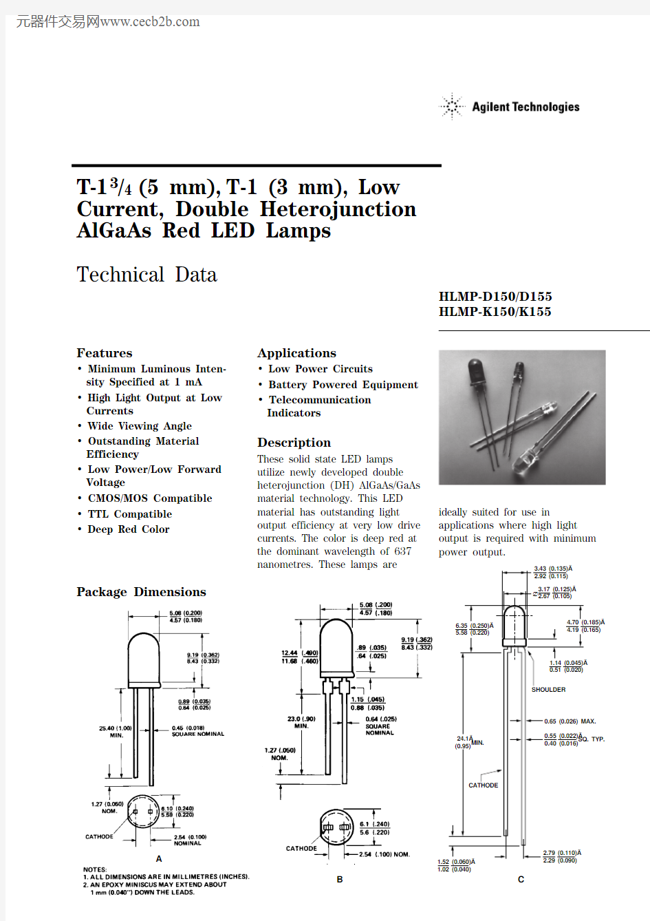
Package Dimensions
A 1.52 (0.060)
1.02 (0.040)
B
Note:
1. θ1/2 is the off axis angle from lamp centerline where the luminous intensity is 1/2 the on-axis value. Part Numbering System
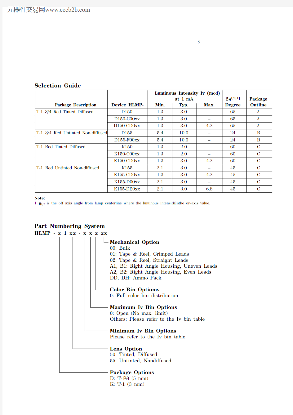
HLMP-x1xx-x x x xx
Mechanical Option
00: Bulk
01: Tape & Reel, Crimped Leads
02: Tape & Reel, Straight Leads
A1, B1: Right Angle Housing, Uneven Leads
A2, B2: Right Angle Housing, Even Leads
DD, DH: Ammo Pack
Color Bin Optioms
0: Full color bin distribution
Maximum Iv Bin Options
0: Open (No max. limit)
Others: Please refer to the Iv bin table
Minimum Iv Bin Options
Please refer to the Iv bin table
Lens Option
50: Tinted, Diffused
55: Untinted, Nondiffused
Package Options
D: T-13/4 (5 mm)
K: T-1 (3 mm)
Absolute Maximum Ratings at T A = 25°C
Peak Forward Current[1]......................................................................................................................300 mA Average Forward Current.......................................................................................................................20 mA DC Current[2].........................................................................................................................................30 mA Power Dissipation.................................................................................................................................87 mW Reverse Voltage (I R = 100 μA)....................................................................................................................5 V Transient Forward Current (10 μs Pulse)[3].........................................................................................500 mA LED Junction Temperature.....................................................................................................................110°C Operating Temperature Range...................................................................................................-20 to +100°C Storage Temperature Range.......................................................................................................-55 to +100°C Lead Soldering Temperature [1.6 mm (0.063 in.) from body]...........................................260°C for 5 seconds Notes:
1. Maximum I PEAK at f = 1 kHz, DF = 6.7%.
2. Derate linearly as shown in Figure 4.
3. The transient peak current is the maximum non-recurring peak current the device can withstand without damaging the LED die and
wire bonds. It is not recommended that the device be operated at peak currents beyond the Absolute Maximum Peak Forward Current.
Electrical/Optical Characteristics at T A = 25°C
Symbol Description Min.Typ.Max.Unit Test Condition V F Forward Voltage 1.6 1.8V I F = 1 mA
V R Reverse Breakdown Voltage 5.015.0V I R = 100 μA
λp Peak Wavelength645nm Measurement at Peak
λd Dominant Wavelength637nm Note 1
?λ1/2Spectral Line Halfwidth20nm
τS Speed of Response30ns Exponential Time
Constant, e-t/T S
C Capacitance30pF V F = 0, f = 1 MHz
RθJ-PIN Thermal Resistance260[3]°C/W Junction to Cathode Lead
210[4]
290[5]
ηV Luminous Efficacy80Im/W Note 2
Notes:
1. The dominant wavelength, λd, is derived from the CIE chromaticity diagram and represents the color of the device.
2. The radiant intensity, I e, in watts per steradian, may be found from the equation I e = l V/ηV, where I V is the luminous intensity in
candelas and ηV is luminous efficacy in lumens/watt.
3. HLMP-D150.
4. HLMP-D15
5.
5. HLMP-K150/-K155.
Figure 3. Relative Luminous Intensity vs. DC Forward Current.Figure 4. Maximum Forward DC Current vs. Ambient Temperature. Derating Based on T J Max. = 110 °
C. Figure 1. Relative Intensity vs. Wavelength.
Figure 2. Forward Current vs. Forward Voltage.
Figure 5. Relative Luminous Intensity vs. Angular Displacement. HLMP-D150.Figure 6. Relative Luminous Intensity vs. Angular Displacement. HLMP-K150.
Figure 7. Relative Luminous Intensity vs. Angular Displacement. HLMP-D155.Figure 8. Relative Luminous Intensity vs. Angular Displacement. HLMP-K155.
6
Maximum tolerance for each bin limit is ±18%.
Mechanical Option Matrix
Mechanical
Option Code Definition
00Bulk Packaging, minimum increment 500 pcs/bag
01Tape & Reel, crimped leads, minimum increment 1300 pcs for T-13/4, 1800 pcs for T-1
02Tape & Reel, straight leads, minimum increment 1300 pcs for T-13/4, 1800 pcs for T-1
A1T-1, Right Angle Housing, uneven leads, minimum increment 500 pcs/bag
A2T-1, Right Angle Housing, even leads, minimum increment 500 pcs/bag
B1T-13/4, Right Angle Housing, uneven leads, minimum increment 500 pcs/bag
B2T-13/4, Right Angle Housing, even leads, minimum increment 500 pcs/bag
DD Ammo Pack, straight leads with minimum 2K increment
DH Ammo Pack, straight leads with minimum 2K increment
Note:
All categories are established for classification of products. Products may not be available in all categories. Please contact your local Agilent representative for further clarification/information.
https://www.doczj.com/doc/d1327873.html,/semiconductors For product information and a complete list of distributors, please go to our web site.
For technical assistance call:
Americas/Canada: +1 (800) 235-0312 or (408) 654-8675
Europe: +49 (0) 6441 92460
China: 10800 650 0017
Hong Kong: (+65) 271 2451
India, Australia, New Zealand: (+65) 271 2394 Japan: (+81 3) 3335-8152(Domestic/Interna-tional), or 0120-61-1280(Domestic Only) Korea: (+65) 271 2194
Malaysia, Singapore: (+65) 271 2054
Taiwan: (+65) 271 2654
Data subject to change.
Copyright ? 2001 Agilent Technologies, Inc. Obsoletes 5968-1438EN
December 11, 2001
5988-2229EN