RS232通讯协议
- 格式:doc
- 大小:66.00 KB
- 文档页数:5
数控机床RS232通讯接⼝及参数介绍数控机床RS232通讯接⼝及参数介绍RS-232-C接⼝在数控机床上有9针或25针串⼝,其特点是简单,⽤⼀根RS232C电缆和电脑进⾏连接,实现在计算机和数控机床之间进⾏系统参数、PMC 参数、螺距补偿参数、加⼯程序、⼑补等数据传输,完成数据备份和数据恢复,以及DNC加⼯和诊断维修。
⼀、RS-232-C简介RS-232-C接⼝(⼜称 EIA RS-232-C)在各种现代化⾃动控制装置上应⽤⼗分⼴泛,是⽬前最常⽤的⼀种串⾏通讯接⼝。
它是在1970年由美国电⼦⼯业协会(EIA)联合贝尔系统、调制解调器⼚家及计算机终端⽣产⼚家共同制定的⽤于串⾏通讯的标准。
它的全名是“据终端设备(DTE)和数据通讯设备(DCE)之间串⾏⼆进制数据交换接⼝技术标准”,该标准规定采⽤⼀个25个脚的DB25连接器,对连接器的每个引脚的信号内容加以规定,还对各种信号的电平加以规定,⼀般只使⽤3~9根引线。
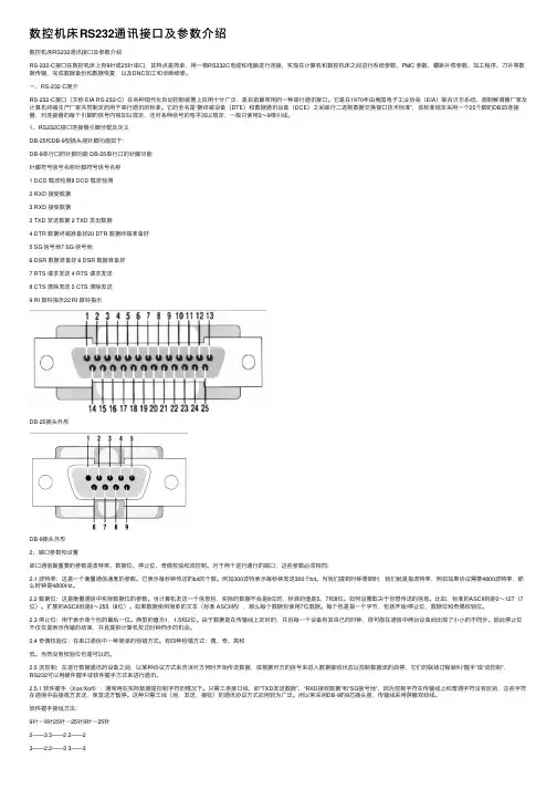
1、RS232C接⼝连接器引脚分配及定义DB-25和DB-9型插头座针脚功能如下:DB-9串⾏⼝的针脚功能 DB-25串⾏⼝的针脚功能针脚符号信号名称针脚符号信号名称1 DCD 载波检测8 DCD 载波检测2 RXD 接受数据3 RXD 接受数据3 TXD 发送数据 2 TXD 发出数据4 DTR 数据终端准备好20 DTR 数据终端准备好5 SG 信号地7 SG 信号地6 DSR 数据准备好 6 DSR 数据准备好7 RTS 请求发送 4 RTS 请求发送8 CTS 清除发送 5 CTS 清除发送9 RI 振铃指⽰22 RI 振铃指⽰DB-25插头外形DB-9插头外形2、端⼝参数和设置串⼝通信最重要的参数是波特率、数据位、停⽌位、奇偶校验和流控制。
对于两个进⾏通⾏的端⼝,这些参数必须相同:2.1 波特率:这是⼀个衡量通信速度的参数。
它表⽰每秒钟传送的bit的个数。
例如300波特表⽰每秒钟发送300个bit。
串口通信RS232和RS485简介PLC与控制设备之间的通信基本上都是基于串行通信接口,采用其对应的通信协议进行控制的,而对于串行通信接口,常用的包括RS232、RS422、RS485。
一、RS232串行通信接口RS-232接口符合美国电子工业联盟(EIA)制定的串行数据通信的接口标准,被广泛用于计算机串行接口外设连接,有些老式PC机上就配置有RS232接口。
RS232的工作方式是单端工作方式,这是一种不平衡的传输方式,收发端信号的逻辑电平都是相对于信号地而言的,RS232最初是DET(数字终端设备)和DCE(数据通信设备)一对一通信,也就是点对点,一般是用于全双工传送,当然也可以用于半双工传送。
此外,RS232是负逻辑,逻辑电平是±5~±15V,传输距离短,只有15米,实际应用可以达到50米,但是再长的距离就须加调制了。
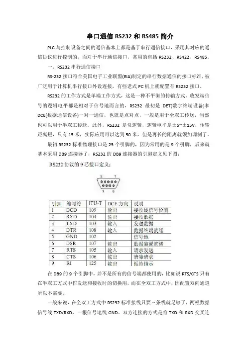
最初RS232标准物理接口是25个引脚的,因为常用的是9个引脚,后来就基本采用DB9连接器了,RS232的DB9连接器的引脚定义见下图:在DB9的9个引脚中,并不是所有的信号端都使用的,比如说RTS/CTS只有在半双工方式中作发送和接收时的切换用,而在全双工方式中,因配置双向通道所以不需要。
一般来说,在全双工方式中RS232标准接线只要三条线就足够了,两根数据信号线TXD/RXD,一根信号地线GND。
双方连接的方式是将TXD和RXD交叉连接,信号地直接相接,然后将各自的RTS/CTS,DSR/DTR短接,将DCD和RI悬空就可以。
二、RS485串行通信接口1、概况为改进RS232通信距离短、速率低的缺点,1983年,RS-485通讯接口被电子工业协会(Electronics Industries Association EIA)批准为一种通讯接口标准。
使用RS-485作为物理层的常用标准协议主要有工业HART总线、modbus协议、Profibus DP等等。
在这一课里,我们一起来学习RS-232C串行通信相关标准及单片机和电脑的RS-232C串行通信接口技术,为学习和开发单片机串口通信应用系统打好基础,希望大家在看完这篇文章后对串行通信有初步的认识。
【通信基本概念】什么是通信?简单地说,不同的系统经由线路相互交换数据,就是通信。
通信的主要目的是将数据从一端传送到另一端,达到数据交换的目的。
例如,从人与人之间的对话、计算机与设备之间的数据交换到计算机与计算机间的数据传送,乃至于广播或卫星都是通信的一种,一个完整的通信系统包括发送端、接收端、转换数据的接口及传送数据的实际信道。
【通信的种类】按照通信的形式可以分为两种,其中一种为并行传输的通信,即并行通信(Parallel Communication),另一种则为串行通信(Serisl Communication)。
这两种通信方式的区别是,并行通信一次的传输数据量为8位(1个字节);而串行通信则一次只能传输1位,传输1字节数据(8位)数据就需要8次才能传出去,因此,它们两者之间的数据传输速度就相差8倍。
看到这里,估计有些朋友会问,既然并行通信的速度是串行通信的8倍,是不是串行通信就不好了?!其实不能这么认为,两种通信方式各有特点,串行通信之所以存活了这么长时间,自然有它的长处。
并行通信虽然可以在一次的数据传输中传送8位,但是数据电压在传送的过程中,容易因为线路及干扰因素使得电压准电位发生变化(主要为电压衰减和信号间相互干扰问题),因而使得传输数据发生错误,通信距离越长,问题越明显,因此并行通信主要用于传输距离较短的场合,如电脑主板的并口LPT1,主要和并行打印机通信。
串行通信一次只传输1位,相对来说,要处理的数据电压只有一个,因此比较不容易漏失数据,通信时候再加上一些校验防范措施后,串行通信的出错就更不容易了,串行通信端口(Serisl Communication Port)在系统控制的范畴中一直占有极其重要的角色,不仅没有因为时代的进步而被淘汰,反而失在规格上愈来愈向其极限挑战,下面我们重点来介绍RS-232C串行通信。

基本的通讯方式有并行通讯和串行通讯两种。
并行通讯:一条信息的各位数据被同时传送的通讯方式称为并行通讯。
并行通讯的特点是:各数据位同时传送,传送速度快、效率高,但有多少数据位就需多少根数据线,因此传送成本高,且只适用于近距离(相距数米)的通讯。
串行通讯:一条信息的各位数据被逐位按顺序传送的通讯方式称为串行通讯。
串行通讯的特点是:数据位传送,传按位顺序进行,最少只需一根传输线即可完成,成本低但送速度慢。
串行通讯的距离可以从几米到几千米。
根据信息的传送方向,串行通讯可以进一步分为单工、半双工和全双工三种。
信息只能单向传送为单工;信息能双向传送但不能同时双向传送称为半双工;信息能够同时双向传送则称为全双工。
而按照串行数据的时钟控制方式,串行通信又可分为同步通信和异步通信两种方式。
异步通信:接收器和发送器有各自的时钟;同步通信:发送器和接收器由同一个时钟源控制。
1、异步串行方式的特点所谓异步通信,是指数据传送以字符为单位,字符与字符间的传送是完全异步的,位与位之间的传送基本上是同步的。
异步串行通信的特点可以概括为:①以字符为单位传送信息。
②相邻两字符间的间隔是任意长。
③因为一个字符中的比特位长度有限,所以需要的接收时钟和发送时钟只要相近就可以,不需同步。
④异步方式特点简单的说就是:字符间异步,字符内部各位同步。
2、异步串行方式的数据格式异步串行通信的数据格式如图1所示,每个字符(每帧信息)由4个部分组成:①1位起始位,规定为低电0;②5~8位数据位,即要传送的有效信息;③1位奇偶校验位;④1~2位停止位,规定为高电平1。
3、同步串行方式的特点所谓同步通信,是指数据传送是以数据块(一组字符)为单位,字符与字符之间、字符内部的位与位之间都同步。
同步串行通信的特点可以概括为:①以数据块为单位传送信息。
②在一个数据块(信息帧)内,字符与字符间无间隔。
③因为一次传输的数据块中包含的数据较多,所以接收时钟与发送进钟严格同步,通常要有同步时钟。
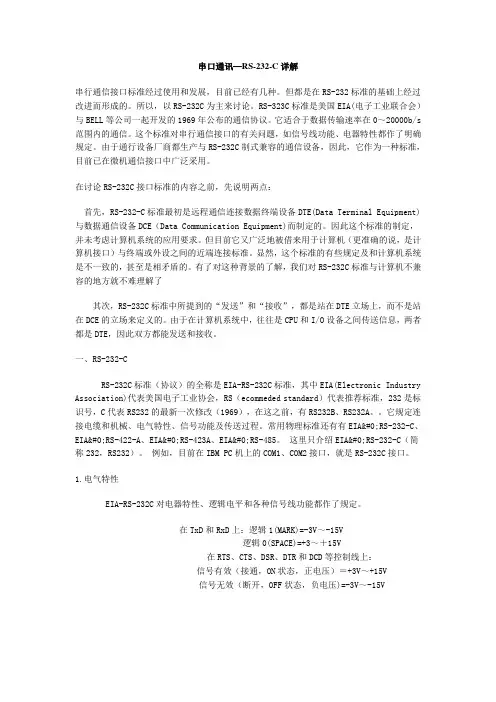
串口通讯—RS-232-C详解串行通信接口标准经过使用和发展,目前已经有几种。
但都是在RS-232标准的基础上经过改进而形成的。
所以,以RS-232C为主来讨论。
RS-323C标准是美国EIA(电子工业联合会)与BELL等公司一起开发的1969年公布的通信协议。
它适合于数据传输速率在0~20000b/s 范围内的通信。
这个标准对串行通信接口的有关问题,如信号线功能、电器特性都作了明确规定。
由于通行设备厂商都生产与RS-232C制式兼容的通信设备,因此,它作为一种标准,目前已在微机通信接口中广泛采用。
在讨论RS-232C接口标准的内容之前,先说明两点:首先,RS-232-C标准最初是远程通信连接数据终端设备DTE(Data Terminal Equipment)与数据通信设备DCE(Data Communication Equipment)而制定的。
因此这个标准的制定,并未考虑计算机系统的应用要求。
但目前它又广泛地被借来用于计算机(更准确的说,是计算机接口)与终端或外设之间的近端连接标准。
显然,这个标准的有些规定及和计算机系统是不一致的,甚至是相矛盾的。
有了对这种背景的了解,我们对RS-232C标准与计算机不兼容的地方就不难理解了其次,RS-232C标准中所提到的“发送”和“接收”,都是站在DTE立场上,而不是站在DCE的立场来定义的。
由于在计算机系统中,往往是CPU和I/O设备之间传送信息,两者都是DTE,因此双方都能发送和接收。
一、RS-232-CRS-232C标准(协议)的全称是EIA-RS-232C标准,其中EIA(Electronic Industry Association)代表美国电子工业协会,RS(ecommeded standard)代表推荐标准,232是标识号,C代表RS232的最新一次修改(1969),在这之前,有RS232B、RS232A。
它规定连接电缆和机械、电气特性、信号功能及传送过程。
APC Smart UPS RS232通讯协议说明
一.硬件层协议
a)RS232接口,使用2400bit/s的波特率,1位起始位,8位数据位,1位停止位,无
奇偶校验位。
b)通讯码制是ASCII码。
二.部分通讯命令描述
以下协议中,ASCII码区分大小写字符,所有的UPS返回信息后面都加上回车换行符(即0d 0a )结束符。
以下分为5类命令:
连接UPS通讯命令,UPS状态命令,电池参数命令,输出UPS的电参数信息命令;这4个命令是:查询方式,也就是上位机发什么命令,UPS就对应的返回什么数据上来。
UPS自动返回的警告信息:是UPS自动向上位机发送警告字符,因为这是RS232通讯的,RS232是全双工的工作模式。
以上协议中:发送的ASCII字符无0d 0a结束符,也无校验。
程序流程如下:。
系统执行READA TA TO指令时的通讯参数:波特率9600数据位8位无校验1位停止位COM1 口RS485 通讯GS()GI()GD()是读出数据的存储类型后面()是存储号站号地址位数都是10进制表示双字节:数据位数为5,则返回数据为:XX XX XX XX XX XX XX XX XX XX (5×4)单字节:数据位数为5,则返回数据为:XX XX XX XX XX(5×2)数据(ASCII码字符,16进制)校验码为16进制系统程序指令:READA TA TO GS#(2)1 0 5 1(外部返回:01 03 05 23 23 23 23 23 23 23 23 23 23 58 0A)READA TA TO读指令,数据放在GS2中,1:站号;0:起始位置;5数据个数双字节本条指令执行后,GS2变量中将有字符:##########。
系统执行READA TA TO指令时,系统通过COM口发出的指令:站号功能码地址位数CRC16XX XX XX XX XX XX XX XX01 03 00 01 00 05 D4 09外部通过COM口,返回系统的数据:站号功能码位数数据(单/双字节)CRC16XX XX XX XXXXXXX XX XX单字节01 03 05 23 23 23 23 23 d5 f201:站号03:功能码05:位数23 23 23 23 23:ASCII码字符数据,单字节5×2。
23(#)F2D5:CRC本条指令系统将收到5个#####。
01 03 05 31 32 33 34 35 e7 3601:站号03:功能码05:位数31 32 33 34 35:ASCII码字符数据,十进制12345 36E7:CRC本条指令系统将收到数据12345。
双字节01 03 05 23 23 23 23 23 23 23 23 23 23 58 0A01:站号03:功能码05:位数23 23 23 23 23 23 23 23 23 23:ASCII码字符数据,双字节5×4。
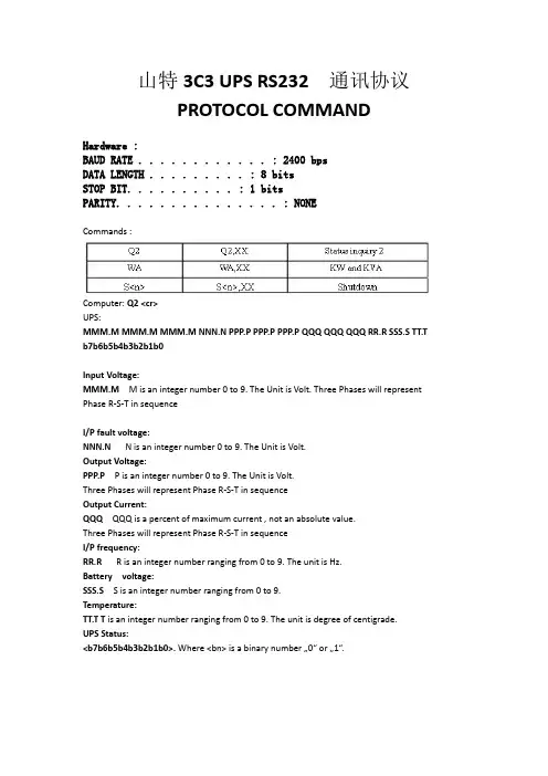
山特3C3 UPS RS232通讯协议PROTOCOL COMMAND山特电子(深圳)有限公司Hardware :BAUD RATE . . . . . . . . . . . . : 2400 bpsDATA LENGTH . . . . . . . . . : 8 bitsSTOP BIT . . . . . . . . . . . . . . : 1 bitsPARITY . . . . . . . . . . . . . . . : NONECommands :Q2 Q2,XX Status inquiry 2WA WA,XX KW and KVAS<n> S<n>,XX Shutdown Computer: Q2 <cr>UPS:MMM.M MMM.M MMM.M NNN.N PPP.P PPP.P PPP.P QQQ QQQ QQQ RR.R SSS.S TT.Tb7b6b5b4b3b2b1b0MMM.M M is an integer number 0 to 9. The Unit is Volt. Three Phases will represent Input Voltage:Phase R-S-T in sequenceI/P fault voltage:NNN.N N is an integer number 0 to 9. The Unit is V olt.Output Voltage: PPP.P P is an integer number 0 to 9. The Unit is Volt.Three Phases will represent Phase R-S-T in sequenceOutput Current: QQQ QQQ is a percent of maximum current , not an absolute value.Three Phases will represent Phase R-S-T in sequenceI/P frequency:RR.R R is an integer number ranging from 0 to 9. The unit is Hz.SSS.S S is an integer number ranging from 0 to 9.Battery voltage:TT.T T is an integer number ranging from 0 to 9. The unit is degree of centigrade. Temperature:UPS Status: <b7b6b5b4b3b2b1b0>. Where <bn> is a binary number …0“ or …1“.UPS status :byte Description7 1 : Utility Fail ( Immediate )6 1 : Battery Low5 1 : Bypass/Boost Active4 1 : UPS Failed3 1 : UPS Type is Standby (0 is On_line)2 1 : Test in Progress1 1 : Shutdown Active0 Reserved (always 0 )<cr>Stop Byte: KW and KVA commandComputer: WA <cr>UPS:WWW.W WWW.W WWW.W VVV.V VVV.V VVV.V TTT.T SSS.S AAA.A AAA.A AAA.A QQQb7b6b5b4b3b2b1b0 <cr>The first of the UPS respond is very similar to the existing inquiry Q2 howeverWWW.W W is an integer number 0 to 9. The Unit is KW. R phase. Three Phases willrepresent Phase R-S-T in sequenceOutput power:VVV.V V is an integer number 0 to 9. The Unit is KVA. R phase. Three Phases will represent Phase R-S-T in sequenceOutput complex power: Total power:TTT.T T is an integer number 0 to 9. The Unit is KW. Include of three phase R,S,&Treal power.SSS.S S is an integer number 0 to 9. The unit is KV A. Include of three phase R,S,&T complex power.Total complex power: Output current: AAA.A A is an integer number 0 to 9. The unit is A. R phase. Three Phases willrepresent Phase R-S-T in sequenceO/P load:QQQ QQQ is maximum of W% or V A%. V A% is a percent of maximum V A. W% is apercent of maximum real power.UPS Status:b7b6b5b4b3b2b1b0 The same of Q2UPS status :Stop Byte:<cr>Shutdown command :Computer: S<n><cr>UPS: Shut UPS output off in <n> minutes.The UPS output will be off in <n> minutes, even if the utility is present.But if the battery under occur before <n> minutes, the output is turned off immediately.After UPS shut down, the controller of UPS monitors the utility. If the utility is there, the UPS will wait for 10 seconds and connect the utility to output.<n> is a number ranging from.2, .3, ..., 01, 02,..., to 10. For example : S.3<cr> --- shut out put off in ( .3) minutes。
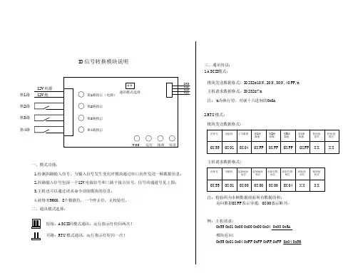
RS232控制命令方式一.通讯协议要求9600bps,8位数据位,1位停止位无校验无流控制;如果用户想把本机输入的第3路信号切换到第1路输出端子上时,(注意当前输入法是否为默认EN)用户可以键入S(或G)代表同步切换命令起始符, 01代表第一输出通道,< 代表切换,03代表输入通道此时,可以看到矩阵切换器动作,执行用户命令。
见右图:矩阵切换器执行用户命令完成后,在用户终端发送$>命令行起始符,准备再次接收用户命令。
二.命令格式VGA单独切换命令起始符为ASCII码的 G(十六进制的47) 或 g(十六进制的67 );同步切换命令起始符为ASCII码的 S (十六进制的53) 或 s (十六进制的73) ;AUDIO单独切换命令符A(十六进制的41)或a(十六进制的71)。
VIDEO单独切换命令符V(十六进制的56)或v(十六进制的76).:为两个数字ASCII码(01~02),表示命令所需控制的输出端口;(数字0~9的ASCII码值为十六进制的30~39)<:ASCII码值为十六进制的3C;:为两个数字ASCII码(01~24),表示命令所需控制的输入端口;:ASCII码回车符(十六进制的0D)。
例如:VGA单独切换时,把04路VGA输入信号切换到02路输出端口,该命令的十六进制;02路输入信号切换到01;控制器向矩阵切换器发送以上格式的十六进制格式命令,也同样可以完成上述操作。
三.关断输出操作命令ASCII码的 S (十六进制的53) 或 s (十六进制的73) ;VGA单独切换命令起始符为ASCII码的“ G”(十六进制的47) 或“g”(十六进制的67; AUDIO单独切换命令起始符为ASCII码的 A(十六进制的41) 或 a(十六进制的61);:为两个数字ASCII码,表示命令所要关断的输出端口;(数字0~9的ASCII码值为十六进制的30~39)О:ASCII码值为十六进制的4F,表示关断命令符;:为1个数字ASCII码(0或1),表示端口关断或打开;:ASCII码回车符(十六进制的0D)。
rs232串口通讯—通信协议(RS232 serial communication protocol)Serial communication protocolAdd time: 2006-11-14 Author: unknown source: unknown entry: abcd200844 read times:--------------------------------------------------------------------------------The so-called communication protocol refers to an agreement between the two sides of communication. The agreement includes uniform rules for data format, synchronization mode, transmission speed, transmission step, check and error correction method, and control character definition, and the two parties must abide by it together. It is also called a communication control procedure, or a transport control procedure, that belongs to the data link layer in the seven - layer reference model of the ISO'S OSI.At present, there are two kinds of communication protocols: asynchronous protocol and synchronous protocol. There are three types of synchronization protocols: character oriented, bit oriented, and byte oriented. Among them, byte counting synchronous protocol is mainly used in DEC's network architecture.Physical interface standard1. basic tasks of serial communication interface(1) data formatting: since the CPU comes from common paralleldata, the interface circuit should have the task of data formatting under different serial communication modes. In asynchronous communication mode, the interface automatically generates start stop type frame data format. In character oriented synchronization, the interface adds synchronization characters before the data block to be transmitted.(2) string conversion: serial transfer, data is bit by bit serial transmission, and computer processing data is parallel data. Therefore, when data is sent to the data transmitter by computer, the serial data is converted into parallel number to be sent into the computer. Therefore, serial to serial conversion is an important task of serial interface circuits.(3) control the data transmission rate: the serial communication interface circuit should have the ability to select and control the data transmission rate baud rate.(4) error detection: when sending, the interface circuit automatically generates parity check bits or other parity codes for the transmitted character data. At reception, the interface circuit checks parity or other check codes of the character to determine whether a transmission error has occurred.(5) carry on TTL and EIA level conversion: CPU and terminal adopt TTL level and positive logic, they are incompatible with the level and negative logic adopted by EIA and need to convert in the interface circuit.(6) providing the signal line required by the EIA-RS-232C interface standard: when using MODEM for long distancecommunication, 9 signal lines are needed, and only 3 signal lines are needed in the near zero MODEM mode. These signal lines are provided by an interface circuit to communicate and control with the MODEM or terminal.2 、 composition of serial communication interface circuitIn order to accomplish the tasks of the serial interface, the serial communication interface circuit is generally composed of a programmable serial interface chip, a baud rate generator, a EIA and an TTL level converter, and an address decoding circuit. Among them, the serial interface chip, along with the large-scale inheritance circuit technology development, the universal synchronous (USRT) and the asynchronous (UART) interface chip kinds are more and more many, as shown in the following table. Their basic functions are similar, and they can implement most of the basic tasks of the serial communication interface mentioned above, and all of them are programmable. With these chips as the core chip of the serial communication interface circuit, the circuit structure will be relatively simple.3. physical standards for serial communicationIn order to make the computer, telephone and other communication devices communicate with each other, now has established several consistent definition and standard of serial communication, these concepts and standards are three aspects: electrical characteristics, transmission rate, signal name and interface standard.1, transmission rate: the so-called transmission rate refers to the number of bits per second, the transmission rate is often called baud rate. A standard baud rate series is specified internationally,The standard baud rate is also the most commonly used baud rate. The standard baud rate series are 110, 300, 600, 1200, 4800, 9600 and 19200. Most CRT terminals are able to work at any baud rate in the range of 110 to 9600. The printer speed is relatively slow due to mechanical transmission and the baud rate is limited, so the general serial printer at 110 baud rate, little needle type printer because of its internal buffer for larger, so you can receive printed information by up to 2400 the speed of Potter. The receive baud rate and baud rate of most interfaces can be set separately, and can be specified by programming.2, RS-232-C standard: the RS-232-C standard has made the stipulation to two aspects, namely signal level standard and control signal line definition. RS-232C uses negative logic rules of logic level, signal level and the TTL level is usually not compatible with RS-232-C, -5V ~ -15V provides for the "1", "0 rules for +5V ~ +15V". Figure 1 is the level conversion between the TTL standard and the RS-232-C standard.Figure 1Two, software protocol1.OSI protocol and TCP/IP protocolFigure 2(1) OSI agreementThe OSI seven layer reference model is not a communication standard. It only gives a stable model that does not necessarily change due to technological development, so that standards and protocols can be developed and coordinated within the scope of the model definition.The general protocol only conforms to several layers of the OSI seven - layer model, such as: EIA-RS-232-C: implements the physical layer. IBM's SDLC (synchronous data link control procedures): data link layer. ANSI's ADCCP (advanced data communication protocol): data link layer IBM BSC (binary synchronous communication protocol): data link layer. The application layer email protocol SMTP is only responsible for sending letters, and POP3 is only responsible for receiving messages.(2) TCP/IP agreementFive layer protocol is implemented.(1) physical layer: the physical layer corresponding to OSI.(2) network interface layer: data link layer similar to OSI.(3) Internet layer: the OSI model is put forward before the Internet network is used, without considering the inter network connection.(4) transport layer: the transport layer corresponding to OSI.(5) application layer: the presentation layer and application layer corresponding to OSI.2. serial communication protocolSerial communication protocol, sub synchronous protocol and asynchronous protocol.(1) asynchronous communication protocol example start stop asynchronous protocolFigure 3Features and formats:Start stop asynchronous protocol is characterized by the transfer of one character to one character, and the transfer of a character that always starts with the start bit to stop the end of the bit, and there is no fixed time interval between characters. Its format is shown in figure 3. In front of each character has a start bit (low level, logical value 0), the character itself has 5 ~ 7 data bits, then the character behind is a parity bit (or no parity bit), the last is a means, or half, or two stop, stop who is behind the indefinite length of idle bits. The stop bit and the idle bit are specified as high levels (logical values) so that the start bit must have a lower jump edge at the start.As you can see from the diagram, the format is defined orsynchronized by the start and stop bits, so it is called the start protocol. When the data is transmitted, the data is in the low position and the high position is behind. Figure 4 shows the waveform 1010001 of the ASCAII code that transmits a character E. When its least significant bit is written to the right, it is the ASCII code E of 1000101=45H.Figure 4Play / stop function: the start bit is actually as a contact signal added in, when it goes low, the transmission began to tell. Its arrival indicates that the following data bits are coming, ready to receive. The stop bit flag is the end of a character, and its occurrence means a character transfer is complete. This gives the communications parties a sign when to start sending and receiving, and when to end. Transfer before sending and receiving parties to the start stop format (including character data bit length, stop bits, no parity bit and there is the odd or even parity etc.) and the data transmission rate of uniform provisions. After the transmission begins, the receiving device continually detects the transmission line to see if a start bit is present. When receiving a series of "1" (stop bits or idle bits), detected a jump along, that start, start after confirmation, began to receive the data bits and the parity bit and stop bit set. After processing, the bit is removed, the data bits are assembled into a parallel byte, and after verification, no parity error is taken to correctly receive a character. Once a character is received, the receiving device has continued testing of the transmission line, monitoring the arrival of the "0" level and the start of the next character until all data transmission iscomplete.The working process can be seen, according to the characters of asynchronous communication transmission, each transmitted character, with a start bit to inform the receiver, in order to re check the synchronization between sender and receiver. If the clock frequency receiving device and transmitting device both slightly deviation, due to error accumulation and this will not lead to dislocation, coupled with the characters between the idle bits for the deviation of a buffer, so the high reliability of asynchronous serial communication. But since additional bits are added to each character before and after the start bit and stop bit, the transmission efficiency is reduced by only about 80%. Therefore, the start stop protocol is generally used on occasions where data rates are slower (less than 19.2kbit/s). In high-speed transport, synchronization protocols are generally used.(2) character oriented synchronization protocolFeatures and formats: a typical example of this protocol is the IBM's binary synchronous communication protocol (BSC). It is characterized by a block of data transmitted by a plurality of characters, instead of just passing one character, and the provisions of the control information of 10 characters as the beginning and end of the data block and the transmission process, they are also called communication control word. Since data blocks are made up of characters, they are called character oriented protocols.Definition of a specific character (control character): it canbe seen from the format above that several specific characters are added to the block before and after. SYN (synchronous Character) is a synchronous character, at the beginning of each frame are SYN, with a SYN called the single synchronization, plus two SYN double synchronous setting synchronous character is contact, when the data transmission, the receiving end time detection, once the synchronous character knows it is a frame start. The next SOH is the sequential start character (Start, Of, Header), which indicates the beginning of the title. The title includes the address of the hospital, the destination address and the routing instructions. STX is the STX (Start Of Text), which marks the transmission of text (data block) start.A block is the body of text to be transmitted, consisting of several characters. The data block is behind the end group (End Of Transmission character ETB Block) or the ETX (End Of Text end character), the ETB is used in the body for a long, divided into several data blocks, are sent in different frames of the occasion, then in each sub block data with the final text character ETX. At the end of the frame is the check code, which checks the field from SOH to ETX (or ETB), and the check method can be vertical and horizontal parity check or CRC. In addition, some other communication control words are used in the character oriented protocol, whose names are shown below:Data transparency implementation: character oriented synchronization protocols, unlike asynchronous start stop protocols,The start and stop bits need to be added before and after each character, so the transmission efficiency is improved. At the same time, because some transmission control words are adopted,the communication control capability and the verification function are enhanced. But there are also some problems, for example, how to distinguish the data character code and specific character code problem, because in the data block is entirely possible with the same specific character code data characters, this could be misleading. For example, the text has a data character that is the same as the end of the character ETX, and the receiver will not mistake it as an ordinary data processing, and mistake it as the end of the text, resulting in errors. Therefore, protocols should have the ability to treat specific characters as ordinary data, which is called data transparency". To this end, the protocol character DLE (Data Link Escape) is set. When a particular character is viewed as data, a DLE is added in front of it so that the receiver receives a DLE to predict that the next character is a data character instead of treating it as a control character. DLE itself is also a specific character, and when it appears in the block, it also adds another DLE in front of it. This method is called character stuffing. Character stuffing is very cumbersome to implement and dependent on character encoding. Because of the above shortcomings, new bit oriented synchronization protocols have been developed.(3) bit oriented synchronization protocolCharacteristics and format: bit oriented protocol is the most representative is the synchronous data link control (SDLC IBM Synchronous Data Link Control), the international standards organization ISO (International Standard Organization) the high level data link control procedures HDLC (High Level Data link Control), the American National Standards Institute(Americal National Standard Institute advanced data communication protocol) ADCCP (Advanced Data Communication Control Procedure). These protocols are characterized by a frame of data transmission can be arbitrary, but it depends on the bit pattern of the contract, and not rely on specific characters to mark the beginning and end of the frame, it is called "bit oriented protocol". The general frame format of this protocol is shown in figure 5:Figure 5Segmentation of frame information: as shown in Figure 5, a frame of SDLC/HDLC information consists of the following fields (Filed), and all fields are transmitted from the significant bit.(1) SDLC/HDLC flag characters: the SDLC/HDLC protocol states that all information transmissions must begin with a flag character and end with the same character. This flag character is 01111110, called the flag field (F). From the start flag to the end mark, a complete unit of information is called a frame (Frame). All the information is transmitted in the form of a frame, while the flag character provides the boundaries of each frame. The receiver can determine the beginning and end of the frame by searching "01111110" to establish frame synchronization.(2) address field and control field: after the flag field, there can be an address field A (Address) and a control field C (Control). The address field is used to specify the address of the secondary station to which it communicates. The controlfield may specify several commands. SDLC specifies the width of the A field and the C field to be 8 bits or 16 bits. The receiver must check the first bit of each address byte. If it is "0", then another address byte is followed; if "1", then the byte is the last address byte. Similarly, if the first byte of the control field is first "0", then there are second control field bytes, otherwise there is only one byte.(3) information field: following the control field is the information field I (Information). The I field contains data to be transmitted, and not every frame must have an information field. That is, the data field can be 0, and when it is 0, this frame is primarily a control command.(4) frame check information: following the information field is the two byte contention check. The frame check field is called the FC (Frame Check) field, or the frame check sequence FCS (Frame, check, Squence). SDLC/HDLC uses 16 bit cyclic redundancy check code CRC (Cyclic, Redundancy, Code). In addition to the flag field and the automatically inserted 0, all information is included in the CRC calculations.Two technical problems in practical application:(1) the "0" bit insertion / deletion: as mentioned above, the SDLC/HDLC agreement in 01111110 as the flag byte, but in the information field may also have the same pattern of characters, in order to distinguish between it and sign, so take a "0" bit insertion and deletion technology. The concrete method is to send all the information at the transmitter (except byte outside), as long as meet 5 consecutive "1" will automaticallyinsert a "0", when the receiver when receiving data (except flag bytes) if received 5 "1", it will automatically followed by a "the 0 is to delete", the original form of information recovery. The "0" bit insertion and deletion process is automatically performed by the hardware.(2) SDLC/HDLC exception ends: if there is an error in the sending process, the SDLC/HDLC protocol usually uses the "Abort" character, or a failure sequence, to invalidate the frame. In the HDLC procedure, 7 consecutive "1" are used as invalid characters, while in SDLC the invalid characters are 8 consecutive "1"". Of course, the "0" bit insertion / deletion technique is not used in the test sequence. The SDLC/HDLC protocol specifies that no data interval is allowed within a frame. Between two frames, the transmitter can continuously output the flag character sequence, or can also output a continuous high level, which is called an idle (Idle) signal.。
RS-232-C详解第一章使用范围最广的一种接口标准是由ITU-T(国际电信联合会电信标准部)定义的标准V.24,事实上,这个标准只对接口的功能方面和过程方面做了定义。
V.24在电气和机械方面引用了其他标准,在美国有一种包括了所有这四个方面内容的规约:EIA-232-F,实质上V.24和EIA-232是一回事,对应关系如下:机械规约:ISO 2110(涉及的是DTE到DCE的实际物理连接)电气规约:V.28 (与电压电平及电压变换的时序有关,DTE和DCE都必须使用相同的编码,相同的电压电平必须表示相同的含义,还必须使用持续时间相同的信号元素,这些特性决定了能够达到的数据率和传输距离。
功能规约:V.24 (定义的各种功能由具有不同含义的各种交换电路来执行,有数据电路,控制电路,时序电路以及电器接地。
过程规约:V.24 (定义了传输数据时发生的事件序列)大多数数据处理设备的数据传输能力是有限的,并且能够达到的数据传输距离也是有限的,因此,这一类设备很少与传输设备或网络直接连接。
D TE通过DCE来使用传输系统。
DCE一端通过传输媒体,负责发送和接收数据,另一端又必须与DTE交互作用(交换数据,控制信息);通过传输线路进行信号交换的两台DCE之间必须互相了解。
为了减轻数据处理设备厂商的负担,开发出一些标准。
这些标准定义了DTE和DCE之间接口的本质。
EIA-232最初是由美国电子工业协会在1962年发布的,当时成为RS-232,现在它已经发展到了第六版EIA-232-F,于1997年发布。
目前使用的V.24和V.28规约分别于1996和1993年发布。
在讨论RS-232C接口标准的内容之前,先说明两点:首先,RS-232-C标准最初是远程通信连接数据终端设备DTE(Data Terminal Equipment)与数据通信设备DCE(Data Communication Equipment)而制定的。
SENTRY RS232 COMMUNICATION PROTOCOLIndexGeneralTEXT MODE communicationBINARY MODE communicationTEXT MODE ups transmitted messagesBINARY MODE ups transmitted messageEasiest way to monitoring UPS statusHow to get UPS shut-down5 chars commands sequenceGeneralThe communication with Sentry HPS/RPS use RS232serial line connection with:-only 3 wires TX , RX and GND;-8bits;-No parity;-Baud rate=9600 , selectable down to 1200 on the ups.There are two ways to communicate; TEXT mode and BINARY mode.Holding on “0” the ECHO function. As set in factory, the Sentry responds only after receiving a command char transmitted form computer.If the ECHO is set on “1” when customizing some operating values, the Sentry transmits chars without receiving any command char from the computer..With ECHO=1, each time that that the alarm condition changes, the Sentry transmits the “TEXT MESSAGE 9” without receiving any command.TEXT MODE communicationThe TEXT MODE communication is opened when computer transmits a sequence of two ASCII characters.The first must be ‘9’ the second must be ‘0’ and in must be into the time interval of 0.5 – 2sec. after the first.The second char is ‘0’ only id the customizing value “INDENT” is equal to ‘0’, as default, otherwise it must be equal to the new value of IDENT.The IDENT value can be set from 0 to 7 to obtain the communication with 8 different machines connected to the same RE232 serial line.After opening TEXT MODE communication the compute can send the ASCII chars form ‘1’ to ‘9’ to have back the “TEXT MESSAGES 9 ”and also to execute a command on the machine in thesame of pushing the buttons panel numbered form 1 to 8.Sending the char’9’, after the opening sequence, it is possible to obtain back the “TEXT MESSAGE 9” without execute any command on the machine, sending the ASCII char ‘:’ it is possible to receive the “TEXT MESSAGE :”.The communication is CLOSED when sending any char different form ‘1’ to ‘9’ or ‘:’ and form three special (BINARY CHSR) for receiving the BINARY MESSAGE.BINARY MODE communicationThe BINARY MESSAGE is obtained each time the computer transmits only one char with value 192 or 204 or 224 decimal if the IDENT is 0, otherwise the char value is =(192 or 204 or 224 decimal ) + the IDENT value,.The char 192 selects the BINARY MESSAGE relative to all operating se values an the values of measures referred to the PRESENT EVENT RECORD.The char 224 selects the BINARY MESSAGE relative to all operating se values an the values of measures referred to the PREVIOUS EVENT RECORD respect to current event record.The char 204 selects the BINARY MESSAGE relative to all operating se values an the values of measures referred to the PREVIOUS EVENT RECORD holding the event record pointer to the position reached when sending the char 224.TEXT MODE ups transmitted messageThe “TEXT MESSAGE 9” is composed by 118 ASCII chars as written below numbered form0 to 117.0 = 13 decimal, carriage return char;1 = 10 decimal, line feed return char;2 = ASCII char = first char show on UPPER row on LCD display on panel;…42 = ASCII char =40th char shown on UPPER row on LCD display on panel;43 = 13 decimal, carriage return char;44 = 10 decimal line feed return char;45 =ASCII char = first char shown on LOWER row on LCD display on panel;…83 = ASCII char = 40th char shown on LOWER row on LCD display on panel;84 = ASCII char = space85 = ASCII char = first char of alarm code ‘a=0000-0000’;94 = ASCII char = last char of alarm code ‘a=0000-0000’;96 = ASCII char = first char of data/time ’yyyy-mm-dd/hh:mm:ss’;115 = ASCII char = last char of data/time ’yyyy-mm-dd/hh:mm:ss’;116 = 13 decimal, carriage return char;117 = 10 decimal, line feed return char.The “TEXT MESSAGE : “is composed by 87 ASCII char as written below numbered form 0 to 86.0 = equal to “TEXT MESSAGE 9”;…83 = equal to “TEXT MESSAGE 9”;84 = led IN. and led OUT. Status on inactive panel (binary value);led IN. on=10 hex, led IN. flashing =30 hex;led OUT. on = 40 hex, led OUT. flashing = C0 hex;85 = led and buzzer status on machine panel(binary value);led BY. on = 01 hex, led BY. flashing = 03 hex;led BAT. on = 04 hex, led BAT. Flashing = 0C hex;BUZZER on = 10 hex, BUZZER short sound =30 hex;86 = same value of selected language on machine panel(binary value).BINARY MODE ups transmitted messageThe “BINARY MESSAGE” is composed by 103 binary values as written below numbered form 0 to 102.0 = echo of char transmitted by computer = 192 decimal + IDENT value;1 = number of message chars, always=103;2 = LSB of word “model value”,3 = MSB of word form “mode value:,model value is = kV A * 10.(for single phase output machine)model value is = 3000 + (kV A * 10),(for three phase output machine);the ups set for parallel operation have model value + 2,the ups in version HPS have the previous model value + 1,4 = LSB of word for software version number,5 = MSB of word for software version number,6= LSB of word for minutes of battery autonomy, (valid only in battery op.);7 = MSB of word for minutes of battery autonomy,(valid only in battery op.);8 = byte for percentage of battery charge value [%];9 = LSB of word “panel menu code”;10 = MSB of word “panel menu code”;11 = byte equal the number of the present event record into history memory,or equal to the number of event record that is being transmittedwhen the previous event record is requested.12 = byte for the SECONDS value (bed code) of the event record time;13 = byte for the MINUTES value (bed code) of the event record time;14 = byte for the HOURS value (bed code) of the event record time;15 = byte for the DAY value (bed code) of the event record time;16 = byte for the MONTHS value (bed code) of the event record time;17 = byte for the YEARS value (bed code) of the event record time;18 = byte for the ALARM internal code, 0=normal operation;19 = LSB of word for “s=….” code, (Look to the translation table of memorized internal codes);20 = MSB of word for “s=….” code, (Look to the translation table of memorized internal codes)21 = LSB of word for “c=….”code, (Look to the translation table of memorized internal codes)22 = MSB of word for “c=….”code, (Look to the translation table of memorized internal codes)23 = LSB of word for “b=….”code, (Look to the translation table of memorized internal codes)24 = MSB of word for “b=….”code, (Look to the translation table of memorized internal codes)25 = LSB of word for first part of “r=….-..”code, (Look to the translation table)26 = SMB of word for first part of “r=….-..”code, (Look to the translation table)27 = byte of second part of “r=….-..”code, (Look to the translation table)28 = LSB of word for first part of “i=….-..”code, (Look to the translation table)29 = MSB of word for first part of “i=….-..”code, (Look to the translation table)30 = byte for second part of “i=….-..”code, (Look to the translation table);31 = LSB of word for first part of “a….-..”code, (Look to the translation table)32 = MSB of word for first part of “a….-..”code, (Look to the translation table);33 = LSB of word for second part of “a….-..”code, (Look to the translation table);34 = MSB of word for second part of “a….-..:code, (Look to the translation table);35 = byte for percentage of input voltage value[%] phase 1 “IN”;36 = byte for percentage of input voltage value[%] phase 2 “IN”;37 = byte for percentage of input voltage value[%] phase 3 “IN”;38 = byte for percentage of input current value[%] phase 1 “IN”;39 = byte for percentage of input current value[%] phase 2 “IN”;40 = byte for percentage of input current value[%] phase 3 “IN”;41= LSB of word for frequency [Hz] of input voltage “IN”;42 = MSB of word for frequency [Hz] of input voltage “IN”;43 = MSB of word for battery voltage value [V olt];44 = LSB of word for battery voltage value [V olt];45 = MSB of word for absolute value of battery current [A];46 = LSB of word for absolute value of battery current [A];the battery current is multiplied by 10 if is charging current with sign value=0;47 = byte for battery sign value, 1=discharging, 0=charging;48 = byte for system temperature value (degree CENTIGRADE);49 = byte for rectifier power module temperature value (degree CENTIGRADE);50 = byte for inverter power module temperature value (degree CENTIGRADE);51 = LSB of word for bypass line input voltage value [V] “BY”, phase 1;52 = MSB of word for bypass line input voltage value [V] “BY”, phase 1;53 = LSB of word for bypass line input voltage value [V] “BY”, phase 2;54 = MSB of word for bypass line input voltage value [V] “BY”, phase 2;55 = LSB of word for bypass line input voltage value [V] “BY”, phase 3;56 = MSB of word for bypass line input voltage value [V] “BY”, phase 3;57 = LSB of word for bypass line input voltage FREQENCY value [Hz] “BY”;58 = MSB of word for bypass line input voltage FREQENCY value [Hz] “BY”;59 = byte for output voltage value [V] phase 1 “OUT”;60 = byte for output voltage value [V] phase 2 “OUT”;61 = byte for output voltage value [V] phase 3 “OUT”;62 = byte for percentage of output RMS current [%Arms], phase 1 “OUT”;63 = byte for percentage of output RMS current [%Arms], phase 2 “OUT”;64 = byte for percentage of output RMS current [%Arms], phase 3 “OUT”;65 = byte for percentage of output peak current [%Apk], phase 1 “OUT”;66 = byte for percentage of output peak current [%Apk], phase 2 “OUT”;67 = byte for percentage of output peak current [%Apk], phase 3 “OUT”;68 = LSB of word for output voltage FREQENCY value [Hz] “OUT”;69 = MSB of word for output voltage FREQENCY value [Hz] “OUT”;70 = byte for inverter output voltage [v], phase to neural value, set into control logic;71 = LSB of word for battery circuit voltage value [V] “BATT”;72 = MSB of word for battery circuit voltage value [V] “BATT”;73 = byte for set system nominal output voltage [v], phase to neural;74 = LSB of word for set battery capacity value [Ah];75 = MSB of word for set battery capacity value [Ah];76 = byte for set battery type value, bits 0, 1, 2,3, 4;from version 10154, also add bit 6 =1 =ECHO function ON,bit 7 =1 =system operating frequency 60Hz.77 = byte for set minutes of prealarm value;78 = byte for set percentage value of output power for AUTO-OFF;79 = byte for set percentage value of bypass line voltage range;80 = byte for set percentage value of bypass line voltage frequency range;81 = LSB of word for “options o=”code, (Look forward for translation table);82 = MSB of word for “other options” , (Look forward for translation table);(before version 10154 ,bit 6=1=ECHO function ON,bit 7=1=system opcrating frequency 60Hz)83 = LSB of word for elapsed HOURS operating on inverter;84 = MSB of word for elapsed HOURS operating on inverter;85 = LSB of word for elapsed HOURS operating on battery;86 = MSB of word for elapsed HOURS operating on battery;87 = LSB of word for number of times of operation on battery (BLACK-OUT);88 = MSB of word for number of times of operation on battery (BLACK-OUT);89 = LSB of word for number of times of operation on battery has been fully discharged;90 = MSB of word for number of times of operation on battery has been fully discharged;91 = ASCII char for thousands of YEARS of date of first machine activation;92 = ASCII char for hundred of YEARS of date of first machine activation;93 = ASCII char for tenth of YEARS of date of first machine activation;94 = ASCII char for unit of YEARS of date of first machine activation;95= byte for set Time_off value;96 = ASCII char for tenth of MONTHS of date of first machine activation;97 = ASCII char for unit of MONTHS of date of first machine activation;98 = byte for set Time_on value;99 = ASCII char for tenth of DAYS of date of first machine activation;100 = ASCII char for unit of DAYS of date of first machine activation;101 = LSB of word for checksum value of transmitted bytes form 0 to 99;102 = MSB of word for checksum value of transmitted bytes form 0 to 99;Translation table of memorized internal codes gives all information on status of opration.char 19 = LSB of word for “s=….”code.bit 0 on = “Power supply error on system card”bit 1 on = “Temporary Error on system power supply card”bit 2 on = “Synchro error on system card”bit 3 on = “Output frequency measure error on system card”bit 4 on = “system OVERTEMPERTURE”bit 5 on = “Initialization error on system card”bit 6 on = “Remotes system SHUT-OFF, active”bit 7 on = “Active aux input on system card”char 20 = MSB of word for “s=….”code.bit 0 on = “System power sypply Permanent fault”(no present on version>10152) bit 1 on = “RS232 DSR signal present”bit 2 on = “Configuration card not present on system card”bit 3 on = “Jumper 2 not present on system card”bit 4 on = “Low voltage form battery or rectifier”bit 5 on = “Prealarm Low voltage form battery or rectifier”bit 6 on = “Battery contactor opened”bit 7 on = “Permanent fault on battery contactor”char 21 = LSB of word for “c=….”code.bit 0 on = “High output peak current, line 1”bit 1 on = “High output peak current, line 2”bit 2 on = “High output peak current, line 3”bit 3 on = “Output OVERLOAD, line 1”bit 4 on = “Output OVERLOAD, line 2”bit 5 on = “Output OVERLOAD, line 3”bit 6 on = “Permanent output OVERLOAD”bit 7 on = “Internal of load insulation loss”, (no present on version>10152)char 22 = MSB of word for “c=….”code.bit 0 on = “ ”bit 1 on = “SWOUT OFF, Output breaker OFF”bit 2 on = “Output aver voltage fail, line 3”bit 3 on = “Output instant voltage fail, line 1”bit 4 on = “Output instant voltage fail, line 2”bit 5 on = “Output instant voltage fail, line 3”bit 6 on = “Output aver voltage fail, line 1”bit 7 on = “Output aver voltage fail, line 2”char 23 = LSB of word for “b=….”code.bit 0 on = “Remote bypass command (inverter-off),active”bit 1 on = “Failure on SCR of bypass line”bit 2 on = “Input bypass line 1 voltage error”bit 3 on = “Input bypass line 2 voltage error”bit 4 on = “Input bypass line 3 voltage error”bit 5 on = “Input bypass line frequency error”bit 6 on = “Input bypass line phases sequence error”bit 7 on = “SWMB on, manual bypass breaker closed” char 24 = MSB of word for “b=….”code.bit 0 on = “Failure on inverter output contactor”bit 1 on = “Inverter output contactor open”bit 2 on = “Bypass line contactor closed”bit 3 on = “Failure on bypass line contactor”bit 4 on = “Permanent fault on bypass SCR”bit 5 on = “Bypass switching inhibited”bit 6 on = “Failure on inverter output contactor”bit 7 on = “command to switch on bypass, active”char 25 = LSB of word for first part of “r=….-..”code.bit 0 on = “High voltage on input line 1”bit 1 on = “High voltage on input line 2”bit 2 on = “High voltage on input line 3”bit 3 on = “Low voltage on input line 1”bit 4 on = “Low voltage on input line 2”bit 5 on = “Low voltage on input line 3”bit 6 on= “Input current not present on line 1”bit 7 on= “Input current not present on line 2”char 26= MSB of word for first part of “r=…_..” code bit 0 on= “Input current not present on line 3”bit 1 on= “Output power limiting on rectifier”bit 2 on= “Regulation error on rectifier”bit 3 on= “Input line frequency error”bit 4 on= “Rectifier error on TEMPERATURE”bit 5 on= “Rectifier HIGHT output voltage”bit 6 on= “Rectifier power supply error”bit 7 on= “Rectifier inhibited”char 27=byte for second part of “r=…_..” codebit 0 on= “Rectifier Failure on one branch” (not present on version >10152)bit 1 on= “Control parallel card power failure”bit 2 on= “Parallel ups connection cable failure or SWMB closed”bit 3 on= “”bit 4 on= “Rectifier Permanent failure” (nor present on version >10152)bit 5 on= “Rectifier-DRV1-signal”bit 6 on= “Rectifier-DRV2-signal”bit 7 on= “Rectifier-DRV3-signal”char 28=LSB of word for first part of “i=…_..” codebit 0 on= “Cables error on inverter driver card” (not present on version >10152) bit 1 on= “Inverter STOP from driver card 3”bit 2 on= “Inverter STOP from driver card 2”bit 3 on= “Inverter over current”bit 4 on= “Cables error into inverter”bit 5 on= “Inverter power supply error”bit 6 on= “inverter-HFDRV R-signal” (parallel synchro fail)bit 7 on= “inverter-HFDRV S-signal” (parallel ups master)char 29=MSB of word for first part of “i=…_..” codebit 0 on= “Inverter Failure”bit 1 on= “Inverter synchro not present”bit 2 on= “Inverter Reset failure”bit 3 on= “Inverter driver card power supply error”bit 4 on= “Inverter high output voltage”bit 5 on= “Inverter high input dc. voltage”bit 6 on= “Inverter over temperature on module 1”bit 7 on= “Inverter over temperature on module 2”char 30=byte for second part of “i=…_..” codebit 0 on= “Inverter over temperature on module 3”bit 1 on= “Inverter STOP from driver card 1”bit 2 on=“inverter-HFDRV T-signal” (parallel serial data fail)bit 3 on= “Inverter inhibited”bit 4 on= “Inverter LOW output voltage”bit 5 on= “Inverter LOW input dc voltage”bit 6 on= “Inverter manual reset”bit 7 on= “Inverter permanent failure” (version >10152)“Inverter cables error on inverter driver card” (version <10152)char 31=LSB of word for first part of “a=…_..” codebit 0 on= “DISRURBANCES ON BYPASS LINE” (inverter nor synchronized to bypass line) bit 1 on= “MANUAL BYPASS ,SWMB ON” (or parallel ups link cable fault)bit 2 on=“BYPASS LINE VOLT FAIL or SWBY,FSCR OFF”bit 3 on= “MAIN LINE VOLTAGE FAIL or SWIN OFF”bit 4 on= “PREALARM LOW BATTERY VOLTAGE”bit 5 on= “LOW INPUT VOLTAGE or OUTPUT OVERLOAD[W]”bit 6 on= “LOW BATTERY CHARGE or CLOSE SWMB”bit 7 on= “OUTPUT OVERLOAD”char 32=MSB of word for first part of “a=…_..” codebit 0 on = “TEMPORARY BYPASS, WAIT”bit 1 on = “BYPASS FOR OUTPUT V A < AUTO-OFF V ALUE”bit 2 on = “FAULT 1: configuration card no present”bit 3 on = “FAULT 2: inverter lockup”bit 4 on = “FAULT 3: output contactors”bit 5 on = “FAULT 4: rectifier lockup”bit 6 on = “FAULT 5: SCR of bypass line”bit 7 on = “FAULT 6: power supply card lockup”char 33=LSB of word for second part of “a=…_..” codebit 0 on = “FAULT 7: system power supply”bit 1 on = “FAULT 8 : one section of rectifier”bit 2 on = “FAULT 9: battery contactor”bit 3 on = “FAULT 10: inverter communication”bit 4 on = “BYPASS FOR OUTPUT OVERLOAD”bit 5 on = “BYPASS COMMAND ACTIVE”bit 6 on = “REMOTE BYPASS COMMAND ACTIVE”bit 7 on = “ ”char 34=MSB of word for second part of “a=…_..” codebit 0 on = “OVERTEMPERATURE or FAN FAILURE”bit 1 on = “INPUT VOLTAGE SEQUENCE NOT OK”,(on bypass line)bit 2 on = “OUTPUT OFF, CLOSE SWOUT OR SWMB”bit 3 on = “SYSTEM OFF COMMAND ACTIVE”bit 4 on = “REMOTE SYSTEM OFF COMMAND”bit 5 on = “MEMORY CHANGED”bit 6 on = “FAULT 11: output voltage fail”bit 7 on = “Auto-off timer active”char 81=LSB of word for “options” “o=…” codebit 0 on = “Key command 47263 masked on display”bit 1 on = “Battery test disabled”,bit 2 on = “Output voltage error alarm delayed”bit 3 on = “SCR fail from bypass to SWBY coil”bit 4 on = “Disable bypass line”bit 5 on = “Time OFF active”bit 6 on = “Auto OFF active”bit 7 on = not usedchar 82=MSB of word for “options2” codebit 0 on = “standby-on operation”bit 1 on = “Lock to bypass line for testing”,bit 2 on = “Standby-off operation”bit 3 on = “Back-feed test active”bit 4 on = “battery parallel operation”bit 5 on =bit 6 on =bit 7 on =Easiest way to monitoring ups statusThe Sentry status of operation and alarms is fully given by the transmitted byte from n.30 =char 30 to n.35=char 34.The most important byte is:Received byte n.32:(char 31=LSB of word for first part of “a=…_..”code)bit 0 on=val.1= “DISRURBANCES ON BYPASS LINE”bit 1 on= val.2= “MANUAL BYPASS ,SWMB ON”bit 2 on= val.3= “BYPASS LINE VOLT FAIL or SWBY,FSCR OFF”bit 3 on= val.4= “MAIN LINE VOLTAGE FAIL or SWIN OFF”bit 4 on= val.8= “PREALARM,LOW BATTERY VOLTAGE ”bit 5 on= val.16= “LOW INPUT VOLTAGE or OUTPUT OVERLOAD[W]”bit 6 on= val.32= “LOW BATTERY CHARGE or CLOSE SWB”bit 7 on= val.64= “OUTPUT OVERLOAD”.The AC-FAIL status is indicated by bit 3 on=val.8= “MAIN LINE VOLTAGE FAIL or SWIN OFF”.The LOW-BATTERY status is indicated by bit 4 on=val.16=“PREALARM,LOW BATTERY VOLTAGE ”.The BYPASS-line-FAIL status is indicated by bit 2 on=val.4=“BYPASS LINE VOLT FAIL or SWBY,FSCR OFF”How to get UPS shut-downAfter started “UPS shut-down” procedure the UPS will switch-off the inverter and it will trip-out the SWBY breaker.After executed the ups shut-off the restoring is possible only manually operating on machine input “SWBY” breaker, because it was tripped.In case of UPS configured for parallel operation and also for model 100kV A and over, the “UPSshut-down” will switch-off the load without tripping the SWBY breaker, therefore it will be able to restart receiving the ASCII char ‘8’In these last cases, if the software version is less than 10154 and over it is possible to restart the ups also with another special 5 chars command sequence, look to “5 chars commands sequence”If the ups software version is less than 10154 it is possible to get the “ups shut-down” only sending a sequence of ASCII characters that simulates the command on machine panel.Before sending the “UPS shut-down” sequence the communication must be already the TEXT MODE or BINARY MODE.The ups shut-down sequence requires to send the ASCII chars 9 0 3 7 4 7 2 6 3 that must be sent with an time interval of 0.6-1.8 seconds between them. Remember that when sending the chars of the “ups shut-down” sequence the UPS responds with the 118 bytes TEXT MODE communication,After sending the “UPS shut-down” sequence it is possible to check that the ups has correctly received the command, checking that the received byte n.35(char 34)of “binary message” looking to bit 4 on=val.16= “REMOTE SYSTEM OFF COMMAND”The UPS shut down is executed after 600 sec. the ups-shut-down sequence is received.The delay cannot be changed, but before the end of the 600 seconds the command can be stopped sending the ASCII char ‘8’5 chars commands sequenceIf the ups software version is 10154 and over, the following commands sequence is recognized. The sequence format has 5 chars :Char 1=176 decimal-identity value, the default is 176, because the default identity value is 0.Char 2=command code value:1=the following value are the seconds of delay to execute UPS shut-down2= the following value are the minutes of delay to restart the UPS after executed UPS shut-down3=command to execute switching to bypass4=command to execute battery test5=command to reset all previous command and to return at normal operation6=command to execute UPS shut-down after the specified second before with command 1 and to automatically restart after minutes specified with command 2Char 3=LSB of value in case of command 1 and 2, zero incase of other commandsChar 4= MSB of value incase of command 1 and 2, zero in case of other commandsChar 5=Sum of previous chars=1+2+3+4NOTE: The ability to restart is only available on UPS configured for parallel operation, or for model 100kV A and over, because the “UPS shut-down” will switch-off the load tripping the SWBY breaker.。
[转]串口(9,25针)通信、串口引脚定义与连接目前较为常用的串口有9针串口(DB9)和25针串口(DB25),通信距离较近时(<12m),可以用电缆线直接连接标准RS232端口(RS485较远),若距离较远,需附加调制解调器(MODEM)。
最为简单且常用的是三线制接法,即地、接收数据和发送数据三脚相连,本文只涉及到最为基本的接法,且直接用RS232相连,以回答前段网友的咨询。
1.DB9和DB25的常用信号脚说明2.RS232C串口通信接线方法(三线制)首先,串口传输数据只要有接收数据针脚和发送针脚就能实现:同一个串口的接收脚和发送脚直接用线相连,两个串口相连或一个串口和多个串口相连∙同一个串口的接收脚和发送脚直接用线相连对9针串口和25针串口,均是2与3直接相连;∙两个不同串口(不论是同一台计算机的两个串口或分别是不同计算机的串口)上面表格是对微机标准串行口而言的,还有许多非标准设备,如接收GPS数据或电子罗盘数据,只要记住一个原则:接收数据针脚(或线)与发送数据针脚(或线)相连,彼些交叉,信号地对应相接,就能百战百胜。
3.串口调试中要注意的几点:∙不同编码机制不能混接,如RS232C不能直接与RS422接口相连,市面上专门的各种转换器卖,必须通过转换器才能连接;∙线路焊接要牢固,不然程序没问题,却因为接线问题误事;∙串口调试时,准备一个好用的调试工具,如串口调试助手、串口精灵等,有事半功倍之效果;∙强烈建议不要带电插拨串口,插拨时至少有一端是断电的,否则串口易损坏。
附:9针脚信号:1 CD Carrier Detect2 RXD Receive Data3 TXD Transmit Data4 DTR Data Terminal Ready5 GND System Ground6 DSR Data Set Ready7 RTS Request to Send8 CTS Clear to Send9 RI Ring IndicatorDCD、DTR、DSR、RTS及CTS等五个状态指示分别代表什么意思?DCD (Data Carrier Detect 数据载波检测)DTR(Data Terminal Ready,数据终端准备好)DSR(Data Set Ready 数据准备好)RTS(Request To Send 请求发送)CTS(Clear To Send 清除发送)在这五个控制信号中,DTR和RTS是DTE设备(数据终端设备,在实际应用中就是路由器)发出的,DSR、CTS和DCD是DCE设备(数据电路终结设备,在实际中就是各种基带MODEM)发出的。
这五个控制信号的协商机制如下:1、在路由器的串口没有配置流控命令的情况下,只要一上电,DTR和RTS就会被置成有效(即只要一加电这两个状态就UP,不管串口有没有接电缆),当路由器检测到对端送过来的DSR、CTS和DCD三个信号时,串口的物理状态就上报UP(任何一个物理信号无效都不会报UP,或者说,这三个信号中只要有一个为DOWN,路由器串口的物理状态就处于DOWN的状态)。
另外,如果在路由器的串口上配置了NO DETECT DSR-DTR命令,DTE侧(路由器)就不会检测对端是否送过来DSR和CTS信号,只要检测到DCD信号,物理层就报UP。
2、如果在路由器的串口上配置了流控命令(具体命令为flowcontrol auto),RTS和CTS两个信号就会用于流量控制(路由器串口和基带Modem之间的数据发送、接收流控)。
当出现数据处理不及时的情况,这两个控制信号就可能处于DOWN的状态串口通信协议百科名片串口通信的概念非常简单,串口按位(bit)发送和接收字节。
尽管比按字节(byte)的并行通信慢,但是串口可以在使用一根线发送数据的同时用另一根线接收数据。
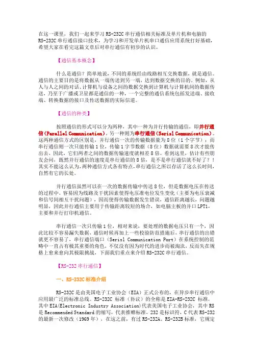
目录什么是串口什么是RS-232什么是RS-485什么是握手DB-9针连接头-------------\ 1 2 3 4 5 /\ 6 7 8 9 /--------------从计算机连出的线的截面。
RS-232针脚的功能:数据:TXD(pin 3):串口数据输出(Transmit Data)RXD(pin 2):串口数据输入(Receive Data)握手:RTS(pin 7):发送数据请求(Request to Send)CTS(pin 8):清除发送(Clear to Send)DSR(pin 6):数据发送就绪(Data Send Ready)DCD(pin 1):数据载波检测(Data Carrier Detect)DTR(pin 4):数据终端就绪(Data Terminal Ready)地线:GND(pin 5):地线其他RI(pin 9):铃声指示RS-485(EIA-485标准)是RS-422的改进,因为它增加了设备的个数,从10个增加到32个,同时定义了在最大设备个数情况下的电气特性,以保证足够的信号电压。
有了多个设备的能力,你可以使用一个单个RS-422口建立设备网络。
出色抗噪和多设备能力,在工业应用中建立连向PC机的分布式设备网络、其他数据收集控制器、HMI或者其他操作时,串行连接会选择RS-485。
RS-485是RS-422的超集,因此所有的RS-422设备可以被RS-485控制。
RS-485可以用超过4000英尺的线进行串行通行。
DB-9 引脚连接-------------\ 1 2 3 4 5 /\ 6 7 8 9 /-------从计算机连出的线的截面。
RS-485的引脚的功能数据:1(DATA-) 2(DATA+)地线:5什么是握手RS-232通行方式允许简单连接三线:Tx、Rx和地线。
但是对于数据传输,双方必须对数据定时采用使用相同的波特率。
尽管这种方法对于大多数应用已经足够,但是对于接收方过载的情况这种使用受到限制。
这时需要串口的握手功能。
在这一部分,我们讨论三种最常用的RS-232握手形式:软件握手、硬件握手和Xmodem。
a,软件握手:我们讨论的第一种握手是软件握手。
通常用在实际数据是控制字符的情况,类似于GPIB 使用命令字符串的方式。
必须的线仍然是三根:Tx,Rx和地线,因为控制字符在传输线上和普通字符没有区别,函数SetXModem允许用户使用或者禁止用户使用两个控制字符XON和XOFF。
这些字符在通信中由接收方发送,使发送方暂停。
例如:假设发送方以高波特率发送数据。
在传输中,接收方发现由于CPU忙于其他工作,输入buffer 已经满了。
为了暂时停止传输,接收方发送XOFF,典型的值是十进制19,即十六进制13,直到输入buffer 空了。
一旦接收方准备好接收,它发送XON,典型的值是十进制17,即十六进制11,继续通信。
输入buffer 半满时,LabWindows发送XOFF。
此外,如果XOFF传输被打断,LabWindows会在buffer达到75%和90%时发送XOFF。
显然,发送方必须遵循此守则以保证传输继续。
b,硬件握手:第二种是使用硬件线握手。
和Tx和Rx线一样,RTS/CTS和DTR/DSR一起工作,一个作为输出,另一个作为输入。
第一组线是RTS(Request to Send)和CTS(Clear toSend)。
当接收方准备好接收数据,它置高RTS线表示它准备好了,如果发送方也就绪,它置高CTS,表示它即将发送数据。
另一组线是DTR(DataTerminal Ready)和DSR(Data SetReady)。
这些现主要用于Modem通信。
使得串口和Modem通信他们的状态。
例如:当Modem已经准备好接收来自PC的数据,它置高DTR线,表示和电话线的连接已经建立。
读取DSR线置高,PC机开始发送数据。
一个简单的规则是DTR/DSR用于表示系统通信就绪,而RTS/CTS用于单个数据包的传输。
在LabWindows,函数SetCTSMode使能或者禁止使用硬件握手。
如果CTS模式使能,LabWindows 使用如下规则:当PC发送数据:RS-232库必须检测CTS线高后才能发送数据。
当PC接收数据:如果端口打开,且输入队列有空接收数据,库函数置高RTS和DTR。
如果输入队列90%满,库函数置低RTS,但使DTR维持高电平。
如果端口队列近乎空了,库函数置高RTS,但使DRT维持高电平。
如果端口关闭,库函数置低RTS和DTR。
c,XModem握手:最后讨论的握手叫做XModem文件传输协议。
这个协议在Modem通信中非常通用。
尽管它通常使用在Modem通信中,XModem协议能够直接在其他遵循这个协议的设备通信中使用。
在LabWindows中,实际的XModem应用对用户隐藏了。
只要PC和其他设备使用XModem协议,在文件传输中就使用LabWindows的XModem函数。
函数是XModemConfig,XModemSend和XModemReceive。
XModem使用介于如下参数的协议:start_of_data、end_of_data、neg_ack、wait_delay、start_delay、max_tries、packet_size。
这些参数需要通信双方认定,标准的XModem有一个标准的定义:然而,可以通过XModemConfig函数修改,以满足具体需要。
这些参数的使用方法由接收方发送的字符neg_ack确定。
这通知发送方其准备接收数据。
它开始尝试发送,有一个超时参数start_delay;当超时的尝试超过max_ties次数,或者收到接收方发送的start_of_data,发送方停止尝试。
如果从发送方收到start_of_data,接收方将读取后继信息数据包。
包中含有包的数目、包数目的补码作为错误校验、packet_size字节大小的实际数据包,和进一步错误检查的求和校验值。
在读取数据后,接收方会调用wait_delay,然后想发送方发送响应。
如果发送方没有收到响应,它会重新发送数据包,直到收到响应或者超过重发次数的最大值max_tries。
如果一直没有收到响应,发送方通知用户传输数据失败。
由于数据必须以pack_size个字节按包发送,当最后一个数据包发送时,如果数据不够放满一个数据包,后面会填充ASCII码NULL(0)字节。
这导致接收的数据比原数据多。
在XModem情况下一定不要使用XON/XOFF,因为XModem发送方发出包的数目很可能增加到XON/OFF控制字符的值,从而导致通信故障。